Embed Size (px)
Citation preview

PROXIMITY SENSORS
www.turck.usThis document provided by Barr-Thorp Electric Co., Inc. 800-473-9123 www.barr-thorp.com

M1 TURCK Inc. 3000 Campus Drive Minneapolis, MN 55441 Application Support: 1-800-544-7769 Fax: (763) 553-0708 www.turck.com
TURCKInnovative Solutions for Automation
Introduction to Sensor Products
Introduction . . . . . . . . . . . . . . . . . . . . . . . . . . . . . . . . . . . M2
Glossary of Terms . . . . . . . . . . . . . . . . . . . . . . . . . . . . . . . M3 - M4
General SpecificationsOperating Principles . . . . . . . . . . . . . . . . . . . . . . . . . . . . . . M5 - M6
Operating Distances . . . . . . . . . . . . . . . . . . . . . . . . . . . . . . M7 - M8
Wiring Instructions - DC (Green)
DC Outputs, Short-Circuit and Overload Protection, TTL Compatible . . . . . . . . . . . . . M10
Sinking and Sourcing . . . . . . . . . . . . . . . . . . . . . . . . . . . . . . . M11
"AD" 2-Wire DC Output . . . . . . . . . . . . . . . . . . . . . . . . . . . . . . M11
"AN4" and "AP4", "AN6(7)" and "AP6(7)" 3-Wire DC Outputs . . . . . . . . . . . . . . . . M12
"VN4" and "VP4", "VN6" and "VP6" 4-Wire DC Outputs . . . . . . . . . . . . . . . . . . M13
"LIU" 4-Wire Linear Analog DC Output . . . . . . . . . . . . . . . . . . . . . . . . M14
Series / Parallel Connection . . . . . . . . . . . . . . . . . . . . . . . . . . M14 - M15
Wiring Instructions - AC (Red)
Short-Circuit and Overload Protection . . . . . . . . . . . . . . . . . . . . . . . . . M16
AC and AC/DC Outputs . . . . . . . . . . . . . . . . . . . . . . . . . . . . . . M17
Series Connection, Mechanical Switches in Series . . . . . . . . . . . . . . . . . . . . M18
Parallel Connection, Mechanical Switches in Parallel . . . . . . . . . . . . . . . . . . . M19
Wiring Instructions - NAMUR (Blue)
NAMUR (Y0 and Y1) Outputs, Typical Output Curves . . . . . . . . . . . . . . . . . . . M20
Typical Intrinsically Safe Installation, Interface Circuits . . . . . . . . . . . . . . . . . . . M21
eurofast® Pinout Diagrams and Mating Cordset . . . . . . . . . . . . . . . . . . M23 - M24
Innovative Sensor Solutions . . . . . . . . . . . . . . . . . . . . . . . . . . M25 - M26
General Specifications. . . . . . . . . . . . . . . . . . . . . . . . . . . . . . . . . . . . . M27 - M32
Compliances and Hazardous Locations
Third Party Compliances . . . . . . . . . . . . . . . . . . . . . . . . . . . . . . M33
Hazardous Location Approvals . . . . . . . . . . . . . . . . . . . . . . . . . M33 - M34
Enclosure Ratings and Material Properties
Enclosure Ratings. . . . . . . . . . . . . . . . . . . . . . . . . . . . . . . . . M35
Material Descriptions - Plastic and Metal . . . . . . . . . . . . . . . . . . . . . . . . M36
Matrix of TURCK Sensor Materials. . . . . . . . . . . . . . . . . . . . . . . . M37 - M38
Chemical Compatibility . . . . . . . . . . . . . . . . . . . . . . . . . . . . . . M38
Selection Guide - Section M
This document provided by Barr-Thorp Electric Co., Inc. 800-473-9123 www.barr-thorp.com

TURCK Inc. 3000 Campus Drive Minneapolis, MN 55441 Application Support: 1-800-544-7769 Fax: (763) 553-0708 www.turck.com M2
IndustrialAutomation
Spec
ifica
tions
How does Proximity Sensing compare to conventional methods?
TURCK proximity sensors are entirely solid state electronic controls that contain no moving parts to wear out as do mechanicalswitches. They require no physical contact for actuation, no cams or linkages, have no contacts to bounce or arc and arecompletely encapsulated, making them impervious to most liquids, chemicals and corrosive agents. In addition, TURCK has a lineof sensors that can be used in hazardous explosive environments without any special enclosures.See Hazardous Area Locations in Section A.
If any of the following conditions exists, a Proximity Sensor should be used:
• The object being detected is too small, too lightweight, or too soft to operate a mechanical switch.
• Rapid response and high switching rates are required, as in counting or ejection control applications.
• Object has to be sensed through non-metallic barriers such as glass, plastic, or paper carton.
• Hostile environments demand improved sealing properties, preventing proper operation of mechanical switches.
• Long life and reliable service are required.
• Fast electronic control system requires bounce-free input signal.
Proximity Sensors are being used today in all industries:
Mining and Metallurgy Sheet Metal FabricationFoundries Automotive and Appliance PlantsAutomatic Assembly and Robotics Electroplating InstallationsConveyor Systems in Airports and Factories Can Plants, Food Processing and BreweriesChemical Plants and Oil Refineries Shipyards, Docks, and Off-shore Drilling RigsSemiconductor Equipment PC-board Handling Machinery
Typical applications:
Parts Detection Void or Jam Control Valve Position IndicationParts Counting Feed Control Missing Parts ControlPositioning Indexing Parts DivertingMotion and Speed Control Inter-lock Control Coin Counting and SortingBottle Cap or Can Lid Detection Liquid Level Control Edge Guide ControlPunch Press Feed and Ejection Control Leak Detection Robotics and ConveyorsBroken or Damaged Tool Detection Machine Programming
Selection Guide - Section M
Important Safety Warning!
TURCK sensors and peripheral devices DO NOT include the self-checking redundant circuitry required topermit their use in personnel safety applications. A device failure or malfunction can result in either anenergized or a de-energized output condition.
Never use these products as sensing devices for personnel protection. Their use as safety devices maycreate unsafe conditions that could lead to serious bodily injury or death.
This document provided by Barr-Thorp Electric Co., Inc. 800-473-9123 www.barr-thorp.com

M3 TURCK Inc. 3000 Campus Drive Minneapolis, MN 55441 Application Support: 1-800-544-7769 Fax: (763) 553-0708 www.turck.com
TURCKInnovative Solutions for Automation
The maximum short-term load current that the outputof a sensor can tolerate.
IP Rating
Ingress Protection rating per IEC 529.
Lateral Approach
The approach of a target perpendicular to the sensorreference axis.
Load
A device or circuit that is operated by the energy outputof another device such as a proximity sensor.
M Threading
ISO 68 Metric straight threading, designated as“Nominal Size” X “Pitch”, in mm. (Ex. M5X0.5)
Minimum Load Current
The minimum amount of current that is required bythe sensor for reliable operation.
NAMUR
The acronym for a European standards organization.
NAMUR Sensor
A 2-wire variable-resistance DC sensor whose operatingcharacteristics conform to DIN 19 234. Requires aremote amplifier for operation. Typically used forintrinsically safe applications.
NEMA Rating
An enclosure rating per NEMA Standard 250.
No-Load Current
The current drawn by a DC proximity sensor from thepower supply when the outputs are not connected to aload.
Nonembeddable (Nonshielded) Proximity Sensor
A sensor is nonembeddable when a specified free zonemust be maintained around its sensing face in ordernot to influence the sensing characteristics.
Normally Closed (N.C.)
The output is OFF when the target is detected bythe sensor.
Normally Open (N.O.)
The output is ON when the target is detected bythe sensor.
NPN Output (Current Sinking)
A transistor output that switches the common or negativevoltage to the load. Load is between sensor and positivesupply voltage.
NPSM Threading
American National Standard Straight Pipe Thread forFree-Fitting Mechanical Parts.
Axial Approach
The approach of the target with its center maintained onthe sensor reference axis.
Axially Polarized Ring Magnet
A ring magnet whose poles are the two flat sides of thedisk. Mounted on pistons for permaprox® cylinderposition sensing through nonmagnetic cylinder walls.
Capacitive Proximity Sensor
A proximity sensor producing an electrostatic field thatsenses conductive targets and nonconductive materialshaving a dielectric constant of >1 within its sensing zone.
Complementary Output
Two outputs, one N.O. and one N.C., that can be usedsimultaneously. The sum of both load currents cannotexceed the sensor’s rated Continuous Load Current.
Continuous Load Current
The maximum current allowed to continuously flowthrough the sensor output in the ON state.
Correction Factors
Percentage of the rated operating distance (Sn) thatrepresents the operating distance for targets constructedfrom materials other than mild steel (mild steel's correctionfactor is 1.0).
Differential Travel (Hysteresis)
The difference between the operating point as the targetapproaches the sensor face, and the release point as thetarget moves away. Given as a percentage of the operatingdistance (Sn).
Dynamic Output
A sensor output that stays energized for a set durationof time, independent of the time the target is present(one-shot).
Embeddable (Shielded) Proximity Sensor
A sensor that can be flush-mounted in any material withoutthat material influencing the sensing characteristics.
Free Zone
The space around a proximity sensor that must bekept free of any material capable of affecting thesensing characteristics.
Inductive Proximity Sensor
A proximity sensor producing an electromagnetic fieldthat senses only metal targets within its sensing zone.
Inductive Magnet Operated Sensor (permaprox ® )
A solid-state sensor consisting of a sensing elementsusceptible to magnetic field strengths of 20-350 Gauss,and switching circuitry similar to that of an inductiveproximity sensor.
This document provided by Barr-Thorp Electric Co., Inc. 800-473-9123 www.barr-thorp.com
TURCK Inc. 3000 Campus Drive Minneapolis, MN 55441 Application Support: 1-800-544-7769 Fax: (763) 553-0708 www.turck.com M4
IndustrialAutomation
Spec
ifica
tions
NPT Threading
American National Standard Taper Pipe Thread.
Off-State (Leakage) Current
The current that flows through the load circuit whenthe sensor is in the OFF-state. Also known as leakageor residual current.
Operating Distance
A distance at which the target approaching the sensing facealong the reference axis causes the output signal to change.
Overload Protection
The ability of a sensor to withstand load currents betweencontinuous load rating and short-circuit condition withno damage.
PG Threading
Steel conduit threading per German standard DIN 40 430.
PNP Output (Current Sourcing)
Transistor output that switches the positive voltage tothe load. Load is between sensor and common.
Programmable Output
Sensor output whose N.O. or N.C. function can beselected by means of a jumper or specific terminalconnection.
Radially Polarized Ring Magnet
A ring magnet whose poles are the inner and outerdiameter rings.
Rated Operating Distance (Sn)
A conventional quantity used to designate the operatingdistance. It does not take into account eithermanufacturing tolerances or variations due to externalconditions such as voltage and temperature.
Reference Axis
An axis perpendicular to the sensing face and passingthrough its center.
Repeatability
The difference between actual operating distancesmeasured at a constant temperature and voltage overan 8-hour period. It is expressed as a percentage (%) ofrated operating distance (Sn).
Response frequencyThe maximum rate that the output can change in responseto the input and still maintain linearity.
Response Time
The time required for the device switching element torespond after the target enters or exits the sensing zone.
Reverse Polarity Protection
Internal components that keep the sensor from beingdamaged by incorrect polarity connection to thepower supply.
Ripple
The alternating component remaining on a DC signal afterrectifying, expressed in percentage of rated voltage.
Sensing Face
The surface of the proximity sensor through which theelectromagnetic (or electrostatic) field emerges.
Short-Circuit Protection
The ability of a sensor to withstand a shorted condition (nocurrent-limiting load connected) without damage.
Slew Rate
The rate of change of the output voltage with respect to astep change in input. A change in output of 0 to 10 volts ata slew rate of 1.25 V/ms would take 8 ms to slew to thenew value.
Solid State
Pertains to devices using semiconductors instead ofmechanical parts.
Static Output
A sensor output that stays energized as long as the targetis present.
Switching Frequency
The maximum number of times per second that the sensorcan change state (ON and OFF) under ideal conditions,usually expressed in Hertz (Hz).
Time-Delay Before Availability
The length of time after power is applied to the sensorbefore it is ready to operate correctly, expressed inmilliseconds (ms).
Uprox Sensor ®
An inductive proximity sensor that detects all metals at thesame range. Uprox sensors are inherently weld-fieldimmune, operate over a wider temperature range and havea higher switching frequency than standard inductivesensors.
Uprox+ Sensor ®
Same basic characteristics as the Uprox Sensor, but with aredesigned multi coil system which provides increasedsensing capabilities. Uprox+ also carries an IP68environmental rating
Weld-Field Immunity (WFI)
The ability of a sensor not to false-trigger in the presenceof strong magnetic fields typically produced by resistancewelders.
Wire-Break Protection
Results in the output being OFF on a DC sensor if eithersupply wire is broken.
This document provided by Barr-Thorp Electric Co., Inc. 800-473-9123 www.barr-thorp.com

M5 TURCK Inc. 3000 Campus Drive Minneapolis, MN 55441 Application Support: 1-800-544-7769 Fax: (763) 553-0708 www.turck.com
TURCKInnovative Solutions for Automation
Operating Principle Ferrite Core
An inductive proximity sensor consists of a coil and ferrite core arrangement, an oscillator and detector circuit, and a solid-stateoutput (Figure 1). The oscillator creates a high frequency field radiating from the coil in front of the sensor, centered around theaxis of the coil. The ferrite core bundles and directs the electro-magnetic field to the front.
When a metal object enters the high-frequency field, eddy currents are induced on the surface of the target. This results in a loss ofenergy in the oscillator circuit and, consequently, a smaller amplitude of oscillation. The detector circuit recognizes a specificchange in amplitude and generates a signal which will turn the solid-state output “ON” or “OFF”. When the metal object leavesthe sensing area, the oscillator regenerates, allowing the sensor to return to its normal state.
Figure 1
Embeddable (Shielded) vs. Nonembeddable (Nonshielded)
Embeddable construction includes a metalband that surrounds the ferrite core and coilarrangement. This helps to “bundle” or directthe electro- magnetic field to the front of thesensor.
Nonembeddable sensors do not have thismetal band; therefore, they have a longeroperating distance and are side sensitive.
Figure 2
See mounting characteristics at the front of each section.
Figure 3
Nonembeddable (Nonshielded Sensor)Embeddable (Shielded Sensor)
This document provided by Barr-Thorp Electric Co., Inc. 800-473-9123 www.barr-thorp.com

TURCK Inc. 3000 Campus Drive Minneapolis, MN 55441 Application Support: 1-800-544-7769 Fax: (763) 553-0708 www.turck.com M6
IndustrialAutomation
Spec
ifica
tions
Operating Principle Uprox ® and Uprox+ ®
Uprox ® and Uprox+ ® Characteristics
• No Correction Factor - Same rated operating distance for all metals.
• Extended Operating Distance - Up to 400% greater than standard inductive sensors when using non-ferrous targets (Figure 4).
• Weld Field Immunity - Uprox is unaffected by strong electromagnetic AC or DC fields because of its unique patented design.
• High Switching Frequencies - Up to 10 times faster than standard inductive sensors.
• Extended Temperature Range - Uprox can withstand temperatures up to 85°C (+185°F) with a ±15% temperature drift.
15
Figure 4
TURCK Uprox is a patented next generationdevelopment of inductive sensors that uses amulti-coil system. Active coil(s) induces eddycurrents on the metal target and passive coil(s)are affected by these eddy currents. Ferrousand nonferrous metals have the same effect onthe two coils. Therefore, all metals, includinggalvanized metals, have the same ratedoperating distance.
TURCK standard inductive sensors use a singlecoil randomly wound around a ferrite core.The single coil both induces eddy currents onthe metal target and is affected by these eddycurrents. Ferrous and nonferrous metals affectthe sensor differently, making it impossible todetect both types of metals at the same ratedoperating distance. See section B of thiscatalog.
Operating distances comparison of Uproxsensors and standard inductive sensors.
StandardNi 8-M18-..
UproxNi15U-M18-..
Figure 5
This document provided by Barr-Thorp Electric Co., Inc. 800-473-9123 www.barr-thorp.com

M7 TURCK Inc. 3000 Campus Drive Minneapolis, MN 55441 Application Support: 1-800-544-7769 Fax: (763) 553-0708 www.turck.com
TURCKInnovative Solutions for Automation
Operating Distance (Sensing Range) Considerations
The operating distance (S) of the different models is basically a function of the diameter of the sensing coil. Maximum operatingdistance is achieved with the use of a standard or larger target. Rated operating distance (Sn) for each model is given in the manual.When using a proximity sensor the target should be within the assured range (Sa).
The operating distance is the distance at which the target approaching the sensing face along the reference axis causes the outputsignal to change.
Operating Distance = S
The rated operating distance is a conventional quantity used to designate the nominal operating distance. It does not take intoaccount either manufacturing tolerances or variations due to external conditions such as voltage and temperature.
Rated Operating Distance = Sn
The effective operating distance is the operating distance of an individual proximity sensor at a constant rated voltage and 23°C(73°F). It allows for manufacturing tolerances.
Effective Operating Distance = Sr 0.9 Sn ≤ Sr ≤ 1.1Sn
The usable operating distance is the operating distance of an individual proximity sensor measured over the operating temperaturerange at 85% to 110% of its rated voltage. It allows for external conditions and for manufacturing tolerances.
Usable Operating Distance = Su 0.81 Sn ≤ Su ≤ 1.21Sn
The assured actuating range is between 0 and 81% of the rated operating distance. It is the range within which the correctoperation of the proximity sensor under specified voltage and temperature ranges is assured.
Assured Operating Range = Sa 0 ≤ Sa ≤ 0.81Sn
A square piece of mild steel having a thickness of 1 mm (0.04 in) is used as a standard target to determine the following operatingtolerances. The length and width of the square is equal to either the diameter of the circle inscribed on the active surface of thesensing face or three times the rated operating distance Sn, whichever is greater.
Standard Target
Figure 6
This document provided by Barr-Thorp Electric Co., Inc. 800-473-9123 www.barr-thorp.com
TURCK Inc. 3000 Campus Drive Minneapolis, MN 55441 Application Support: 1-800-544-7769 Fax: (763) 553-0708 www.turck.com M8
IndustrialAutomation
Spec
ifica
tions
Operating Distance (Sensing Range) Considerations
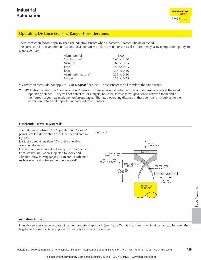
The difference between the “operate” and “release”points is called differential travel (See shaded area inFigure 7).It is factory set at less than 15% of the effectiveoperating distance.Differential travel is needed to keep proximity sensorsfrom “chattering” when subjected to shock andvibration, slow moving targets, or minor disturbancessuch as electrical noise and temperature drift.
Differential Travel (Hysteresis)
Figure 7
Inductive sensors can be actuated in an axial or lateral approach (See Figure 7). It is important to maintain an air gap between thetarget and the sensing face to prevent physically damaging the sensors.
Actuation Mode
These correction factors apply to standard inductive sensors when a nonferrous target is being detected.The correction factors are nominal values. Deviations may be due to variations in oscillator frequency, alloy composition, purity andtarget geometry.
Aluminum foil 1.00Stainless steel 0.60 to 1.00Mercury 0.65 to 0.85Lead 0.50 to 0.75Brass 0.35 to 0.50Aluminum (massive) 0.35 to 0.50Copper 0.25 to 0.45
• Correction factors do not apply to TURCK Uprox ® sensors. These sensors see all metals at the same range.
• TURCK also manufactures “nonferrous only” sensors. These sensors will selectively detect nonferrous targets at the ratedoperating distance. They will not detect ferrous targets; however, ferrous targets positioned between them and anonferrous target may mask the nonferrous target. The rated operating distance of these sensors is not subject to thecorrection factors that apply to standard inductive sensors.
This document provided by Barr-Thorp Electric Co., Inc. 800-473-9123 www.barr-thorp.com

M9 TURCK Inc. 3000 Campus Drive Minneapolis, MN 55441 Application Support: 1-800-544-7769 Fax: (763) 553-0708 www.turck.com
TURCKInnovative Solutions for Automation
Maximum Switching Frequency
Many critical applications for proximity sensors involve their use in weld field environments. AC and DC resistance welders usedin assembly equipment and other construction machines often require in excess of 20 kA to perform their weld function.Magnetic fields generated by these currents can cause false outputs in standard sensors.
TURCK has pioneered the design and development of inductive proximity sensors that not only survive such environments, butremain fully operative in them.
The limit of the weld field immunity depends on the kind of field (AC or DC), the housing size of the sensor and its location in thefield. For example, in an AC or DC weld field, the “/S34" inductive sensors can be positioned one inch from a 20 kA currentcarrying bus. See Section H for a list of weld field immune sensors.
Reference values for magnetic induction:
Minimum parameters for measuring at maximum switching frequency are shown in Figure 8. Using a smaller target or space mayresult in a reduction of a specific sensor’s maximum switching frequency and decrease sensor to target air gap tolerance. See pageM7 for determining dimension “A” of standard target.
Weld Field Immunity
Distance [mm]
I [kA]
5102050100
12.5
80 mT160 mT320 mT800 mT
1600 mT
25
40 mT80 mT160 mT400 mT800 mT
50
20 mT40 mT80 mT200 mT400 mT
100
10 mT20 mT40 mT100 mT200 mT
Gauss = 10 x mT
This document provided by Barr-Thorp Electric Co., Inc. 800-473-9123 www.barr-thorp.com

TURCK Inc. 3000 Campus Drive Minneapolis, MN 55441 Application Support: 1-800-544-7769 Fax: (763) 553-0708 www.turck.com M10
IndustrialAutomation
Spec
ifica
tions
Two-, three-, or four-wire proximity sensors contain a transistor oscillator and a snap-action amplifier. This provides exceedinglyhigh accuracy to a set switching point, even with very slowly approaching targets. Switching characteristics are unaffected by supplyvoltage fluctuations within the specified limits.
The sensors can drive electromechanical relays, counters, solenoids, or electronic modules, and interface directly with logic systemsor programmable controllers without additional interface circuitry. They are available with either NPN output transistors (currentsinking) or PNP output transistors (current sourcing).
Load current ratings vary from 100 mA to 200 mA depending on physical size. Standard voltage range is 10-30 VDC with certaintypes available for 10-65 VDC. All models incorporate wire-break, transient and reverse polarity protection.Power-On false pulse suppression is also standard.
TURCK DC sensors with a Voltage Range designation of "4", "6" or "8" in the part number are short-circuit and overload protected(automatic reset). These sensors incorporate a specially designed circuit which continuously monitors the ON state output currentfor a short-circuit or overload condition. If either of these fault conditions occurs, the output is turned OFF and pulse tested untilthe fault is removed. This added protection causes a ≤1.8 V drop across the output in the normal ON state. This may be a problemwhen interfacing with some logic low inputs (see TTL compatibility).
Some solid-state loads requiring NPN (sinking) input signals need a ≤0.8 V signal to reliably turn ON. TURCK DC sensors with TTLcompatibility are designated with the voltage range "7" in the part number. The output of these sensors will have a voltage drop of≤0.7 V (0.3 V typical), which will ensure reliable operation. Do not use voltage ranges "4" and '6" when TTL compatibility isrequired.
TTL Compatibility
DC Outputs
Short-Circuit and Overload Protection
Voltage drop is measured from output wire black (BK) to ground wire blue (BU).
Figure 2Figure 1
This document provided by Barr-Thorp Electric Co., Inc. 800-473-9123 www.barr-thorp.com

M11 TURCK Inc. 3000 Campus Drive Minneapolis, MN 55441 Application Support: 1-800-544-7769 Fax: (763) 553-0708 www.turck.com
TURCKInnovative Solutions for Automation
DC Outputs
DC Sourcing and Sinking
Figure 6 Sink (NPN)
“AG” 2-Wire DC Output
Note: TURCK 2-wire DC sensors with an "AD" designation are not polarity sensitive and can be used to sink or source a load.
2-Wire DC
Figure 4 Sink (NPN)Figure 3 Source (PNP)
3-Wire DCFigure 5 Source (PNP)
Figure 9
“AD” 2-Wire DC OutputFigure 7 Figure 8
This document provided by Barr-Thorp Electric Co., Inc. 800-473-9123 www.barr-thorp.com

TURCK Inc. 3000 Campus Drive Minneapolis, MN 55441 Application Support: 1-800-544-7769 Fax: (763) 553-0708 www.turck.com M12
IndustrialAutomation
Spec
ifica
tions
DC Outputs
“AN6(7)" and”AP6" 3-Wire DC Outputs
Figure 13 Wiring DiagramFigure 12 Electronic Output Circuit
Figure 11 Wiring DiagramFigure 10 Electronic Output Circuit
“AN4" and ”AP4" 3-Wire DC Outputs
NPN transistor(i.e. current sinkingnegative switching)N.O. output
PNP transistor(i.e. current sourcingpositive switching)N.O. output
NPN transistor(i.e. current sinkingnegative switching)N.O. output
PNP transistor(i.e. current sourcingpositive switching)N.O. output
• Order current sinking (NPN) sensors with the voltage range “7" only when low voltage dropfor TTL gates is required. In all other cases, order sensors with voltage ranges ”4" or “6".
TURCK TIP
This document provided by Barr-Thorp Electric Co., Inc. 800-473-9123 www.barr-thorp.com

M13 TURCK Inc. 3000 Campus Drive Minneapolis, MN 55441 Application Support: 1-800-544-7769 Fax: (763) 553-0708 www.turck.com
TURCKInnovative Solutions for Automation
DC Outputs
“VN6" and ”VP6" 4-Wire DC Outputs
Figure 17 Wiring DiagramFigure 16 Electronic Output Circuit
NPN transistor(i.e. current sinkingnegative switching)complementaryoutput (SPDT)
PNP transistor(i.e. current sourcingpositive switching)complementaryoutput (SPDT)
“VN4" and ”VP4" 4-Wire DC Outputs
NPN transistor(i.e. current sinkingnegative switching)complementaryoutput (SPDT)
PNP transistor(i.e. current sourcingpositive switching)complementaryoutput (SPDT)
Figure 15 Wiring DiagramFigure 14 Electronic Output Circuit
This document provided by Barr-Thorp Electric Co., Inc. 800-473-9123 www.barr-thorp.com

TURCK Inc. 3000 Campus Drive Minneapolis, MN 55441 Application Support: 1-800-544-7769 Fax: (763) 553-0708 www.turck.com M14
IndustrialAutomation
Spec
ifica
tions
Series/Parallel Connection
DC Outputs
Figure 20 Wiring Diagram
“LIU" 4-Wire Linear Analog DC Output
Figure 19 Typical Response Curve
Figure 18 Electronic Output Circuit
Linear Analog Output; Current and Voltage
Logic functions with DC proximity sensors:
Self-contained proximity sensors can be wired in series or parallel to perform such logic functions as AND, OR, NAND, NOR. Thewiring diagrams show the hook-up of four sensors with NPN and PNP outputs.Take into account the accumulated no-load current and voltage drop per sensor added in the series string.
Parallel-connection:
N.O. sensors: OR Function(target present, any sensor: load “on”)
N.C. sensors: NAND Function(target present, all sensors: load “off”)
• To prevent the load from seeing the cumulative voltage drop of multiple 3-wire sensors in series, alternating polarity sensors canbe used provided that the desired polarity is at the load.
• Wiring 3-wire sensors in series delays the load by the accumulated “time delay before availability" of all sensors in the string.
Series-connection:
N.O. sensors: AND Function(target present, all sensors: load “on”)
N.C. sensors: NOR Function(target present, any sensor: load “off”)
TURCK TIP
This document provided by Barr-Thorp Electric Co., Inc. 800-473-9123 www.barr-thorp.com

M15 TURCK Inc. 3000 Campus Drive Minneapolis, MN 55441 Application Support: 1-800-544-7769 Fax: (763) 553-0708 www.turck.com
TURCKInnovative Solutions for Automation
Series/Parallel Connection
Figure 22 PNP Connection
Figure 21 NPN Connection
This document provided by Barr-Thorp Electric Co., Inc. 800-473-9123 www.barr-thorp.com

TURCK Inc. 3000 Campus Drive Minneapolis, MN 55441 Application Support: 1-800-544-7769 Fax: (763) 553-0708 www.turck.com M16
IndustrialAutomation
Spec
ifica
tions
Short-Circuit and Overload Protection
TURCK AC sensors with the Voltage Range designation “30", “32" or ”40" are short-circuit and overload protected (manual reset).These sensors incorporate a specially designed circuit which continuously monitors the ON state output current for a short-circuit oroverload condition. If either of these fault conditions occurs, the output is latched OFF until the power has been cycled OFF andON again.
Always select short-circuit and overload protected sensors whenever possible.
DO NOT…operate a proximity sensor from a wall outlet without a load.This is considered a “dead” short and can cause catastrophicdamage to nonshort-circuit protected sensors.
DO NOT…forget to ground. AC and AC/DC sensors must be grounded or there existsa potential of electrical shock.
DO NOT…operate an incandescent light bulb as a load.The extremely high cold current will cause an overload condition.
CAUTION!
DO NOT…directly operate a motor with a proximity sensor.The inrush current can cause an overload condition.Always use a motor starter, relay or other appropriate device.
This document provided by Barr-Thorp Electric Co., Inc. 800-473-9123 www.barr-thorp.com

M17 TURCK Inc. 3000 Campus Drive Minneapolis, MN 55441 Application Support: 1-800-544-7769 Fax: (763) 553-0708 www.turck.com
TURCKInnovative Solutions for Automation
These sensors are used as pilot devices for AC-operated loads such as relays, contactors, solenoids, etc. The solid-state outputpermits use of the sensors directly on the line in series with an appropriate load. They, therefore, replace mechanical limit switcheswithout alteration of circuitry, where operating speed or environmental conditions require the application of solid-state sensors.
These sensors are typically available in a voltage range of 20-250 VAC. All models are available with either normally open (N.O.),normally closed (N.C.) or programmable outputs (from N.O. to N.C.). Careful consideration must be given to the voltage dropacross AC/DC sensors when used at 24 VDC.
Since the sensors are connected in series with the loadby means of only two leads, an off-state current flowsthrough the load in the magnitude of approximately1.7 mA.
This, however, does not affect the proper and reliableperformance of most AC loads. Another characteristicof solid state sensors is a 5 to 7 volt drop developedacross the sensor in the ON state.
All models contain a snubber network to protectagainst transients from inductive loads, which cancause false triggering.
Figure 2 AC/DC Outputs - "30", "32", "40" SCP
AC and AC/DC Outputs
Figure 1 AC/DC Outputs - "3", "31", "33", non-SCP
Figure 3 Electro-Mechanical Equivalents
SCP = Short-circuit Protected
This document provided by Barr-Thorp Electric Co., Inc. 800-473-9123 www.barr-thorp.com

TURCK Inc. 3000 Campus Drive Minneapolis, MN 55441 Application Support: 1-800-544-7769 Fax: (763) 553-0708 www.turck.com M18
IndustrialAutomation
Spec
ifica
tions
Mechanical Switches in Series
Series-connection: (Figure 4)
N.O. sensors: AND Function(target present, all sensors: load “on”)
N.C. sensors: NOR Function(target present, any sensor: load “off”)
The maximum number of sensors to be operated in series depends on the stability of the line voltage and the operatingcharacteristics of the load in question. The supply voltage minus the accumulative on state voltage drop across the series connection(approximately 7 Vrms per sensor) must be ≥ the minimum required load voltage.
Series Connection
Figure 4
Figure 5
Figure 6
Solution:A 33 kΩ, 1W by-pass resistor can be added across the mechanicalcontact to eliminate the time delay before availability. This willallow enough leakage current to keep the sensor ready forinstantaneous operation.
Problem:Mechanical switches in series with proximity sensors should alwaysbe avoided because they can create an open circuit, leaving theproximity sensor without power. In order to operate properly, aproximity sensor should be powered continuously. A typicalproblem encountered when the mechanical contact closes whilethe target is present is a short time delay that is experienced beforethe load energizes (time delay before availability).
This document provided by Barr-Thorp Electric Co., Inc. 800-473-9123 www.barr-thorp.com

M19 TURCK Inc. 3000 Campus Drive Minneapolis, MN 55441 Application Support: 1-800-544-7769 Fax: (763) 553-0708 www.turck.com
TURCKInnovative Solutions for Automation
Mechanical Switches in Parallel
Parallel Connection
Wiring AC proximity sensors in parallel can result in inconsistent operation and should generally be avoided.
On-state voltage drop: With any sensor ON, the voltage across all other sensors is typically 7 Vrms. Since the minimum ratedvoltage for AC sensors is 20 Vrms, no other sensor with a target present can turn ON until the first sensor turns OFF. This transitionis not instantaneous due to the time delay before availability, during which the load may drop out.
Leakage current through the load: This is equal to the total leakage of all sensors wired in parallel. Too much leakage into a solidstate load can cause the input to turn ON and not turn OFF. Small relays may not drop out if the leakage current exceeds therelay’s holding current.
Parallel Connection: (Figure 7)
N.O. sensors: OR Function(target present, any sensor: load “on”)
N.C. sensors: NAND Function(target present, all sensors: load “off”)
Problem:As previously discussed, proximity sensors should bepowered continuously to avoid the time delay beforeavailability during power-up.
With mechanical switches in parallel, the sensor isshorted out every time the contact is closed, leaving itwithout power. If the target is present when themechanical contact is opened, a small delay will beexperienced during which the load may drop out.
Solution:This delay can be avoided by adding a resistor in series with the mechanicalcontact. The voltage drop developed across the resistor with the contact closedwill be enough to keep the sensor active. Use the formula below to determinethe value and wattage.
Minimum resistor wattage rating: E x I
Example: 20 V x 180 mA = 3.6 W ≈ 5watts recommended
Formula:
minimum operating voltage of proximity sensorR =
load current at operating voltage
Example:
20 VR =
180 mAR = 110 Ω
Figure 9
Figure 7
Figure 8
This document provided by Barr-Thorp Electric Co., Inc. 800-473-9123 www.barr-thorp.com

TURCK Inc. 3000 Campus Drive Minneapolis, MN 55441 Application Support: 1-800-544-7769 Fax: (763) 553-0708 www.turck.com M20
IndustrialAutomation
Spec
ifica
tions
Typical Output Curves
NAMUR (Y0 and Y1) Output
NAMUR sensors are 2-wire sensing devices used with switching amplifiers. Because of the small amount of energy needed tooperate NAMUR sensors, they can be used in intrinsically safe applications.
The operation of this sensor is similar to that of a variable resistor with a change in impedance as a target approaches the sensor.When no metal is being sensed, the inductive sensor is in a low impedance state and draws a current of more than 2.2 mA. Whena metal target enters the high-frequency field radiated from the sensor head, the impedance increases as the target approaches.When fully damped, the sensor draws less than 1.0 mA. Note: For capacitive and inductive magnet operated sensors, the currentchange characteristics are opposite.
The current differential from the undamped to the damped (metal present) state is used to trigger an amplifier at a definedswitching point. These sensors contain a relatively small number of components, which allows the construction of small devices andalso assures a high degree of reliability.
In the undamped and damped state, the devices have fairly low impedance and are therefore, unaffected by most transients.NAMUR sensor circuits operate on direct current. Therefore, cable runs of several sensors may be run parallel to one anotherwithout mutual interference.
Note:The typical curve ofcurrent versus sensingdistance with 8.2 V DCsupply and 1 kΩ sourceimpedence. All NAMUR(Y0 and Y1) sensors arecalibrated to pass through1.55 mA at nominalsensing range ±10%.
The NAMUR (Y0 and Y1) sensor behaveslike a variable resistor when a targetapproaches.The impedence increases or decreasesbetween 1 kΩ and 8 kΩ.
Figure 3
Figure 1
Figure 2
This document provided by Barr-Thorp Electric Co., Inc. 800-473-9123 www.barr-thorp.com

M21 TURCK Inc. 3000 Campus Drive Minneapolis, MN 55441 Application Support: 1-800-544-7769 Fax: (763) 553-0708 www.turck.com
TURCKInnovative Solutions for Automation
Custom Interface Circuits
Typical Intrinsically Safe Installation
For guidance on installation of TURCK intrinsically safe systems, refer to the Instrument Society of America publicationISA-RP12.6-1995, “Wiring Practices for Hazardous (Classified) Locations Instrumentation".
The complete line of Intrinsically Safe and Associated Apparatus is featured in the TURCK “Isolated Barriers and Amplifiers” catalog.
NAMUR sensors can operate outside the nominal operating values when the sensor is used in a nonhazardous area.The supply voltage limits are: Vmin = 5 VDC; Vmax = 30 VDC
Within this voltage range the load resistance Ri must be adjusted for the supply voltage.The following table gives typical values:
Figure 4
Figure 6Figure 5
If these values are used, the current Isn corresponds to the rated operating distance (Sn) of the sensor.NAMUR sensors are short-circuit protected up to 15 VDC and reverse polarity protected up to 10 VDC.
Vsupply (DC) Ri (k ) Isn (mA) I (mA)
5 0.39 ≈0.7 ≈0.112 1.8 ≈2.3 ≈0.315 2.2 ≈2.9 ≈0.424 3.9 ≈3.8 ≈0.5
This document provided by Barr-Thorp Electric Co., Inc. 800-473-9123 www.barr-thorp.com

TURCK Inc. 3000 Campus Drive Minneapolis, MN 55441 Application Support: 1-800-544-7769 Fax: (763) 553-0708 www.turck.com M22
IndustrialAutomation
Spec
ifica
tions
Notes:
This document provided by Barr-Thorp Electric Co., Inc. 800-473-9123 www.barr-thorp.com

M23 TURCK Inc. 3000 Campus Drive Minneapolis, MN 55441 Application Support: 1-800-544-7769 Fax: (763) 553-0708 www.turck.com
TURCKInnovative Solutions for Automation
eurofast ® Pinout Diagrams and Mating Cordset
RD4X-H1141
Mating Cordset: RK 4.21T-* (Y0)
RD4X-H1143
Mating Cordset: RK 4.2T-*
AD4X-H1141
Mating Cordset: RK 4.2T-*
AD4X-H1144
Mating Cordset: RK 4.2T-*/S674
AP6X-H1141/H1341
Mating Cordset: RK 4T-*
AN6X-H1141/H1341
Mating Cordset: RK 4T-*
AG41X-H1341
Mating Cordset: RK 4.2T-*/S748
This document provided by Barr-Thorp Electric Co., Inc. 800-473-9123 www.barr-thorp.com

TURCK Inc. 3000 Campus Drive Minneapolis, MN 55441 Application Support: 1-800-544-7769 Fax: (763) 553-0708 www.turck.com M24
IndustrialAutomation
Spec
ifica
tions
eurofast ® Pinout Diagrams and Mating Cordset
RP6X-H1143/H1343
Mating Cordset: RK 4T-*
VN4X2-H1141/H1341
Mating Cordset: RK 4.4T-*
RP6X-H1141
Mating Cordset: RK 4.4T-*
RN6X-H1141
Mating Cordset: RK 4.4T-*
AG41X-H3141
Mating Cordset: RK 4.2T-*/S748
VP4X2-H1141/H1341
Mating Cordset: RK 4.4T-*
RN6X-H1143/H1343
Mating Cordset: RK 4.42T-*
This document provided by Barr-Thorp Electric Co., Inc. 800-473-9123 www.barr-thorp.com

M25 TURCK Inc. 3000 Campus Drive Minneapolis, MN 55441 Application Support: 1-800-544-7769 Fax: (763) 553-0708 www.turck.com
TURCKInnovative Solutions for Automation
Innovative Sensor and Connector Solutions
TURCK is the market leader in providing innovative sensor and connectivity solutions for industrial automation. CombineTURCK's high quality, high performance sensors with our ability to quickly mold multiple styles of cordsets give our customersan infinite selection of unique connectorized sensing solutions.
All TURCK sensors with potted-in cable are available with customized cable length and connector options. The broadestselection of connector options provides custom sensing solutions for the most diverse industrial applications.Because it is TURCK, you can expect the same fast, flexible support. Even with custom configurations, YOUR sensor canoften be made within several days. Best of all, minimum quantity for YOUR sensor; ONE!
+ Length in Meters +
Bi 8U-MT18-AN6X + 0.5 Meters + RS 4T
New Part Number = Bi 4-M12-AN6X-0.5-RS 4T
eurofast ®
MaleConnector
Bi 5-MT18-AN6X - 0.2M - RS 4T
CableLength(meters)
Cable Sensor
Bi 2-EG08K-AP6X - 0.5M - RS 4T
CableLength(meters)
Cable Sensor eurofastMale
Connector
Part numbers are developed through your TURCK representative or application support.In general, the formula below illustrates how to configure a custom, connectorized TURCK sensor.
Sensors with Connector Examples:
This document provided by Barr-Thorp Electric Co., Inc. 800-473-9123 www.barr-thorp.com

TURCK Inc. 3000 Campus Drive Minneapolis, MN 55441 Application Support: 1-800-544-7769 Fax: (763) 553-0708 www.turck.com M26
IndustrialAutomation
Spec
ifica
tions
CableLength(meters)
minifast ®
MaleConnector
Cable Sensor
Bi 8-M18-AN6X - 0.1M - RSM 40
CableLength(meters)
eurofastMale
Connector
Cable Sensor
Bi10U-EM30-AP6X - 0.2M - RS 4T
CableLength(meters)
eurofastMale
Connector
Cable Sensor
Ni 5U-Q10S-AN6X - 0.4M - RS 4T
CableLength(meters)
picofast ®
MaleConnector
Cable Sensor
Bi 2-Q5.5-AP6X - 0.3M - PSG 3
Sensors with Connector Examples:
picofast ®
MaleConnector
Bi 8U-Q10-APX2 - 0.1M - PSG 3M
CableLength(meters)
Cable Sensor
Innovative Sensor and Connector Solutions
This document provided by Barr-Thorp Electric Co., Inc. 800-473-9123 www.barr-thorp.com

M27 TURCK Inc. 3000 Campus Drive Minneapolis, MN 55441 Application Support: 1-800-544-7769 Fax: (763) 553-0708 www.turck.com
TURCKInnovative Solutions for Automation
Ripple . . . . . . . . . . . . . . . . . . . . . . . . . . . . . . . ≤10%Differential Travel (Hysteresis) . . . . . . . . . . . . . . . . . . . 3-15% (5% typical)Voltage Drop Across Conducting Sensor . . . . . . . . . . . . . . Non-polarized (AD) <5.0 V
. . . . . . . . . . . . . . . . . . . . . . . . . . . . . . . . . . Polarized (AG) <4.0 VTrigger Current for Overload Protection . . . . . . . . . . . . . . ≥120 mAMinimum Load Current . . . . . . . . . . . . . . . . . . . . . . ≥3.0 mAOff-State (Leakage) Current . . . . . . . . . . . . . . . . . . . . ≤0.8 mAPower-On Effect . . . . . . . . . . . . . . . . . . . . . . . . . . Per IEC 947-5-2Transient Protection . . . . . . . . . . . . . . . . . . . . . . . . Per EN 60947-5-2Shock . . . . . . . . . . . . . . . . . . . . . . . . . . . . . . . 30 g, 11 msVibration . . . . . . . . . . . . . . . . . . . . . . . . . . . . . . 55 Hz, 1 mm Amplitude in all 3 PlanesRepeatability . . . . . . . . . . . . . . . . . . . . . . . . . . . . ≤2% of Rated Operating Distance
2-Wire DC - (AD4, RD4, AG41 and RG41)
Differential Travel (Hysteresis) . . . . . . . . . . . . . . . . . . . 1-10% (5% typical)Nominal Voltage . . . . . . . . . . . . . . . . . . . . . . . . . . 8.2 VDC (EN60947-5-6)Resistance Change fromNonactivated to Activated Condition . . . . . . . . . . . . . . . . typical <1.0 to >8.0 kΩResulting Current Change . . . . . . . . . . . . . . . . . . . . . ≥2.2 mA to ≤1.0 mARecommended Switching Point forRemote Amplifier . . . . . . . . . . . . . . . . . . . . . . . . . >1.2 to <2.1 mA, typ. 1.55 mA ON/1.75 mA OFFPower-On Effect . . . . . . . . . . . . . . . . . . . . . . . . . . Realized in AmplifierReverse Polarity Protection . . . . . . . . . . . . . . . . . . . . . IncorporatedWire-Break Protection . . . . . . . . . . . . . . . . . . . . . . . Realized in AmplifierTransient Protection . . . . . . . . . . . . . . . . . . . . . . . . Realized in AmplifierShock . . . . . . . . . . . . . . . . . . . . . . . . . . . . . . . 30 g, 11 msVibration . . . . . . . . . . . . . . . . . . . . . . . . . . . . . . 55 Hz, 1 mm Amplitude in all 3 PlanesRepeatability . . . . . . . . . . . . . . . . . . . . . . . . . . . . ≤2% of Rated Operating Distance
2-Wire DC NAMUR - (Y0 and Y1)
Ripple . . . . . . . . . . . . . . . . . . . . . . . . . . . . . . . ≤10%Differential Travel (Hysteresis) . . . . . . . . . . . . . . . . . . . ≤1 mm (Depends on magnet)Maximum Switching Capacity . . . . . . . . . . . . . . . . . . . 10 WNo-Load Current . . . . . . . . . . . . . . . . . . . . . . . . . . 0 mAMaximum Approach Velocity . . . . . . . . . . . . . . . . . . . ≤10 m/sPower-On Effect . . . . . . . . . . . . . . . . . . . . . . . . . . Per IEC 947-5-2Transient Protection . . . . . . . . . . . . . . . . . . . . . . . . Per EN 60947-5-2Shock . . . . . . . . . . . . . . . . . . . . . . . . . . . . . . . 30 g, 11 msVibration . . . . . . . . . . . . . . . . . . . . . . . . . . . . . . 55 Hz,1 mm Amplitude in all 3 PlanesRepeatability . . . . . . . . . . . . . . . . . . . . . . . . . . . . ≥ ±0.1 mm
. . . . . . . . . . . . . . . . . . . . . . . . . . . . . . . . . . (constant temperature & voltage)Temperature Drift . . . . . . . . . . . . . . . . . . . . . . . . . ≤0.1 mmVoltage Drop. . . . . . . . . . . . . . . . . . . . . . . . . . . . ≤0.5 Volts
REED (AC) and (DC) - (AR7X)
This document provided by Barr-Thorp Electric Co., Inc. 800-473-9123 www.barr-thorp.com

TURCK Inc. 3000 Campus Drive Minneapolis, MN 55441 Application Support: 1-800-544-7769 Fax: (763) 553-0708 www.turck.com M28
IndustrialAutomation
Spec
ifica
tions
Ripple. . . . . . . . . . . . . . . . . . . . . . . . . . . . . . . . ≤10%Differential Travel (Hysteresis) . . . . . . . . . . . . . . . . . . . . 3-15% (5% typical)Voltage Drop Across Conducting Sensor. . . . . . . . . . . . . . . ≤1.8 V. . . . . . . . . . . . . . . . . . . . . . . . . . . . . . . . . . . - Si...K08/K10(AP71, AN7) . ≤0.7 V. . . . . . . . . . . . . . . . . . . . . . . . . . . . . . . . . . . - Bi/Ni../S34 . . . . . . . . ≤1.8 V. . . . . . . . . . . . . . . . . . . . . . . . . . . . . . . . . . . - Bi 2-Q8SE-AP/AN.. . . . . ≤2.5 VTrigger Current for Overload Protection . . . . . . . . . . . . . . . ≥220 mA on 200 mA Load Current. . . . . . . . . . . . . . . . . . . . . . . . . . . . . . . . . . . ≥170 mA on 150 mA Load Current. . . . . . . . . . . . . . . . . . . . . . . . . . . . . . . . . . . ≥120 mA on 100 mA Load CurrentOff-State (Leakage) Current . . . . . . . . . . . . . . . . . . . . . <100 μANo-Load Current . . . . . . . . . . . . . . . . . . . . . . . . . . <10 mA (Uprox ≤15 mA)Time Delay Before Availability . . . . . . . . . . . . . . . . . . . ≤8 msPower-On Effect . . . . . . . . . . . . . . . . . . . . . . . . . . Per IEC 947-5-2Reverse Polarity Protection . . . . . . . . . . . . . . . . . . . . . IncorporatedWire-Break Protection . . . . . . . . . . . . . . . . . . . . . . . IncorporatedTransient Protection. . . . . . . . . . . . . . . . . . . . . . . . . Per EN 60947-5-2Shock . . . . . . . . . . . . . . . . . . . . . . . . . . . . . . . . 30 g, 11 msVibration . . . . . . . . . . . . . . . . . . . . . . . . . . . . . . 55 Hz, 1 mm Amplitude in all 3 PlanesRepeatability . . . . . . . . . . . . . . . . . . . . . . . . . . . . ≤2% of Rated Operating Distance. . . . . . . . . . . . . . . . . . . . . . . . . . . . . . . . . . . Bi 2-Q8SE-AP/AN.. ≤5% of Rated Operating Distance
Ripple. . . . . . . . . . . . . . . . . . . . . . . . . . . . . . . . ≤10%Differential Travel (Hysteresis) . . . . . . . . . . . . . . . . . . . . 3-15% (5% typical)Voltage Drop Across Conducting Sensor. . . . . . . . . . . . . . . ≤1.8 V at 200 mATrigger Current for Overload Protection . . . . . . . . . . . . . . . ≥220 mA on 200 mA Load Current. . . . . . . . . . . . . . . . . . . . . . . . . . . . . . . . . . . ≥170 mA on 150 mA Load Current. . . . . . . . . . . . . . . . . . . . . . . . . . . . . . . . . . . ≥120 mA on 100 mA Load CurrentOff-State (Leakage) Current . . . . . . . . . . . . . . . . . . . . . <100 μANo-Load Current . . . . . . . . . . . . . . . . . . . . . . . . . . <10 mA (Uprox ≤15 mA)Power-On Effect . . . . . . . . . . . . . . . . . . . . . . . . . . Per IEC 947-5-2Reverse Polarity Protection . . . . . . . . . . . . . . . . . . . . . IncorporatedWire-Break Protection . . . . . . . . . . . . . . . . . . . . . . . IncorporatedTransient Protection. . . . . . . . . . . . . . . . . . . . . . . . . Per EN 60947-5-2Shock . . . . . . . . . . . . . . . . . . . . . . . . . . . . . . . . 30 g, 11 msVibration . . . . . . . . . . . . . . . . . . . . . . . . . . . . . . 55 Hz, 1 mm Amplitude in all 3 PlanesRepeatability . . . . . . . . . . . . . . . . . . . . . . . . . . . . ≤2% of Rated Operating Distance
4-Wire DC (VN, VP)
3-Wire DC - (AN, RN, AP, RP)
This document provided by Barr-Thorp Electric Co., Inc. 800-473-9123 www.barr-thorp.com

M29 TURCK Inc. 3000 Campus Drive Minneapolis, MN 55441 Application Support: 1-800-544-7769 Fax: (763) 553-0708 www.turck.com
TURCKInnovative Solutions for Automation
Line Frequency. . . . . . . . . . . . . . . . . . . . . . . . . . . 40-60 HzDifferential Travel (Hysteresis) . . . . . . . . . . . . . . . . . . . 3-15% (5% typical)Voltage Drop Across Conducting Sensor . . . . . . . . . . . . . . ≤6.0 V at 400 mA
. . . . . . . . . . . . . . . . . . . . . . . . . . . . . . . . . . 8 and 12 mm ≤6.0 V at 100 mAContinuous Load Current . . . . . . . . . . . . . . . . . . . . . ≤400 mA
. . . . . . . . . . . . . . . . . . . . . . . . . . . . . . . . . . 8 and 12 mm ≤100 mAOff-State (Leakage) Current . . . . . . . . . . . . . . . . . . . . ≤1.7 mAMinimum Load Current . . . . . . . . . . . . . . . . . . . . . . ≥5.0 mAInrush Current . . . . . . . . . . . . . . . . . . . . . . . . . . . ≤8.0 A (≤10 ms, 5% Duty Cycle)Power-On Effect . . . . . . . . . . . . . . . . . . . . . . . . . . Per IEC 947-5-2Transient Protection . . . . . . . . . . . . . . . . . . . . . . . . Per EN 60947-5-2Shock . . . . . . . . . . . . . . . . . . . . . . . . . . . . . . . 30 g, 11 msVibration . . . . . . . . . . . . . . . . . . . . . . . . . . . . . . 55 Hz, 1 mm Amplitude in all 3 PlanesRepeatability . . . . . . . . . . . . . . . . . . . . . . . . . . . . ≤2% of Rated Operating Distance
2-Wire AC w/o Short-Circuit Protection - (AZ, RZ, FZ)
Line Frequency. . . . . . . . . . . . . . . . . . . . . . . . . . . 40-60 HzDifferential Travel (Hysteresis) . . . . . . . . . . . . . . . . . . . 3-15% (5% typical)Voltage Drop Across Conducting Sensor . . . . . . . . . . . . . . ≤6.0 V at 400 mA
. . . . . . . . . . . . . . . . . . . . . . . . . . . . . . . . . . 8 and 12 mm ≤6.0 V at 100 mATrigger Current for Overload Protection . . . . . . . . . . . . . . AC: ≥440 mA; DC: ≥330 mA
. . . . . . . . . . . . . . . . . . . . . . . . . . . . . . . . . . 8 and 12 mm AC: ≥120 mA; DC: ≥120 mAContinuous Load Current . . . . . . . . . . . . . . . . . . . . . AC: ≤400 mA; DC: ≤300 mA
. . . . . . . . . . . . . . . . . . . . . . . . . . . . . . . . . . 8 and 12 mm AC: ≥100 mA; DC: ≥100 mAOff-State (Leakage) Current . . . . . . . . . . . . . . . . . . . . ≤1.7 mA (AC)
. . . . . . . . . . . . . . . . . . . . . . . . . . . . . . . . . . ≤1.5 mA (DC)Minimum Load Current . . . . . . . . . . . . . . . . . . . . . . ≥3.0 mAInrush Current . . . . . . . . . . . . . . . . . . . . . . . . . . . 4.0 A (≤20 ms, 10% Duty Cycle)Power-On Effect . . . . . . . . . . . . . . . . . . . . . . . . . . Per IEC 947-5-2Transient Protection . . . . . . . . . . . . . . . . . . . . . . . . Per EN 60947-5-2Shock . . . . . . . . . . . . . . . . . . . . . . . . . . . . . . . 30 g, 11 msVibration . . . . . . . . . . . . . . . . . . . . . . . . . . . . . . 55 Hz, 1 mm Amplitude in all 3 PlanesRepeatability . . . . . . . . . . . . . . . . . . . . . . . . . . . . ≤2% of Rated Operating Distance
2-Wire AC/DC w/Short-Circuit Protection - (ADZ, RDZ, FDZ, VDZ)
This document provided by Barr-Thorp Electric Co., Inc. 800-473-9123 www.barr-thorp.com

TURCK Inc. 3000 Campus Drive Minneapolis, MN 55441 Application Support: 1-800-544-7769 Fax: (763) 553-0708 www.turck.com M30
IndustrialAutomation
Spec
ifica
tions
Ripple. . . . . . . . . . . . . . . . . . . . . . . . . . . . . . . . ≤10%Differential Travel (Hysteresis) . . . . . . . . . . . . . . . . . . . . 2-20 (5% typical)Voltage Drop Across Conducting Sensor. . . . . . . . . . . . . . . ≤1.8 V at 200 mATrigger Current for Overload Protection . . . . . . . . . . . . . . . ≥220 mALeakage (Off-State) Current . . . . . . . . . . . . . . . . . . . . . <100 μANo-Load Current . . . . . . . . . . . . . . . . . . . . . . . . . . ≤15 mAPower-On Effect . . . . . . . . . . . . . . . . . . . . . . . . . . Per IEC 947-5-2Reverse Polarity Protection . . . . . . . . . . . . . . . . . . . . . IncorporatedWire-Break Protection . . . . . . . . . . . . . . . . . . . . . . . IncorporatedTransient Protection. . . . . . . . . . . . . . . . . . . . . . . . . Per EN 60947-5-2Shock . . . . . . . . . . . . . . . . . . . . . . . . . . . . . . . . 30 g, 11 msVibration . . . . . . . . . . . . . . . . . . . . . . . . . . . . . . 55 Hz, 1 mm Amplitude in all 3 PlanesRepeatability . . . . . . . . . . . . . . . . . . . . . . . . . . . . ≤2% of Rated Operating DistanceTemperature Drift. . . . . . . . . . . . . . . . . . . . . . . . . . <±20% of Rated Operating Distance
4-Wire DC Capacitive - (VP, VN)
Ripple. . . . . . . . . . . . . . . . . . . . . . . . . . . . . . . . ≤10%Differential Travel (Hysteresis) . . . . . . . . . . . . . . . . . . . . 2-20% (5% typical)Voltage Drop Across Conducting Sensor. . . . . . . . . . . . . . . ≤1.8 V at 200 mATrigger Current for Overload Protection . . . . . . . . . . . . . . . ≥220 mAOff-State (Leakage) Current . . . . . . . . . . . . . . . . . . . . . <100 μANo-Load Current . . . . . . . . . . . . . . . . . . . . . . . . . . ≤15 mAPower-On Effect . . . . . . . . . . . . . . . . . . . . . . . . . . Per IEC 947-5-2Reverse Polarity Protection . . . . . . . . . . . . . . . . . . . . . YesWire-Break Protection . . . . . . . . . . . . . . . . . . . . . . . YesTransient Protection. . . . . . . . . . . . . . . . . . . . . . . . . Per EN 60947-5-2Shock . . . . . . . . . . . . . . . . . . . . . . . . . . . . . . . . 30 g, 11 msVibration . . . . . . . . . . . . . . . . . . . . . . . . . . . . . . 55 Hz, 1 mm Amplitude in all 3 PlanesRepeatability . . . . . . . . . . . . . . . . . . . . . . . . . . . . ≤2% of Rated Operating DistanceTemperature Drift. . . . . . . . . . . . . . . . . . . . . . . . . . <±20% of Rated Operating Distance
Line Frequency . . . . . . . . . . . . . . . . . . . . . . . . . . . 50-60 HzHysteresis (Differential Travel) . . . . . . . . . . . . . . . . . . . . 2-20% (5% typical)Voltage Drop Across Conducting Sensor. . . . . . . . . . . . . . . ≤7.0 V at 500 mAOff-State (Leakage) Current . . . . . . . . . . . . . . . . . . . . . ≤1.7 mAMinimum Load Current . . . . . . . . . . . . . . . . . . . . . . . ≥5.0 mAInrush Current . . . . . . . . . . . . . . . . . . . . . . . . . . . ≤8.0 A (≤10 ms, 5% Duty Cycle)Power-On Effect . . . . . . . . . . . . . . . . . . . . . . . . . . Per IEC 947-5-2Transient Protection. . . . . . . . . . . . . . . . . . . . . . . . . Per EN 60947-5-2Shock . . . . . . . . . . . . . . . . . . . . . . . . . . . . . . . . 30 g, 11 msVibration . . . . . . . . . . . . . . . . . . . . . . . . . . . . . . 55 Hz, 1 mm Amplitude in all 3 PlanesRepeatability . . . . . . . . . . . . . . . . . . . . . . . . . . . . ≤2% of Rated Operating DistanceTemperature Drift. . . . . . . . . . . . . . . . . . . . . . . . . . <±20% of Rated Operating Distance
2-Wire AC Capacitive - (AZ, RZ)
3-Wire DC Capacitive - (AP, RP, AN, RN)
This document provided by Barr-Thorp Electric Co., Inc. 800-473-9123 www.barr-thorp.com

M31 TURCK Inc. 3000 Campus Drive Minneapolis, MN 55441 Application Support: 1-800-544-7769 Fax: (763) 553-0708 www.turck.com
TURCKInnovative Solutions for Automation
Ripple . . . . . . . . . . . . . . ≤10%No-Load Current . . . . . . . . ≤8.0 mAFrequency Output. . . . . . . . 1-10 kHzLinearity Tolerance . . . . . . . ±5% of full scaleTemperature Tolerance . . . . . ±0.06% / °CReverse Polarity Protection . . . IncorporatedWire-Break Protection. . . . . . Incorporated
Transient Protection . . . . . . . Per EN 60947-5-2Shock . . . . . . . . . . . . . . 30 g, 11 msVibration . . . . . . . . . . . . 55 Hz, 1 mm Amplitude,. . . . . . . . . . . . . . . . . in all 3 planes
Repeatability . . . . . . . . . . ≤1%. . . . . . . . . . . . . . . . . (0.5% after 30 min. warm up)
3-Wire DC Analog - (LF10)
LF = Linear frequency (1-10 kHz) output.
Ripple . . . . . . . . . . . . . . ≤10%No-Load Current . . . . . . . . ≤8.0 mACurrent Output . . . . . . . . . 4-20 mA/RL ≤500 ΩLinearity Tolerance . . . . . . . ±3% of full scaleTemperature Drift . . . . . . . . ±0.06% / °CReverse Polarity Protection . . . Incorporated
Wire-Break Protection. . . . . . IncorporatedTransient Protection . . . . . . . Per EN 60947-5-2Shock . . . . . . . . . . . . . . 30 g, 11 msVibration . . . . . . . . . . . . 55 Hz, 1 mm Amplitude,. . . . . . . . . . . . . . . . . in all 3 planes
Repeatability . . . . . . . . . . ≤1%. . . . . . . . . . . . . . . . . (0.5% after 30 min. warm up)
3-Wire DC Analog - (LI2)
LI = indicates current output only.2 = Indicates a variance to standard which is 0-20 mA.
Ripple . . . . . . . . . . . . . . ≤10%No-Load Current . . . . . . . . ≤8.0 mAVoltage Output . . . . . . . . . 0-10 V/RL ≥4.7 kΩLinearity Tolerance . . . . . . . ±5% of full scaleTemperature Tolerance . . . . . ±0.06% / °CReverse Polarity Protection . . . IncorporatedWire-Break Protection. . . . . . IncorporatedTransient Protection . . . . . . . Per EN 60947-5-2Shock . . . . . . . . . . . . . . 30 g, 11 msOff-State (Leakage) Current . . . <100 mA
Voltage Drop Across Conducting Sensor . . . . . . . ≤1.8 VTrigger Current forOverload Protection. . . . . . . ≥220 mA on. . . . . . . . . . . . . . . . . 200 mA load current
No-Load Current . . . . . . . . <10 mAVibration . . . . . . . . . . . . 55 Hz, 1 mm Amplitude,. . . . . . . . . . . . . . . . . in all 3 planes
Repeatability . . . . . . . . . . ≤1%. . . . . . . . . . . . . . . . . (0.5% after 30 min. warm up)
4-Wire DC Analog - (LUAP6X)
Ripple . . . . . . . . . . . . . . ≤10%No-Load Current . . . . . . . . ≤8.0 mAVoltage Output . . . . . . . . . 0-10 V/RL ≥4.7 kΩCurrent Output . . . . . . . . . 0-20 mA/RL ≤500 ΩLinearity Tolerance . . . . . . . ±3% of full scaleTemperature Tolerance . . . . . ±0.06% / °CReverse Polarity Protection . . . Incorporated
Wire-Break Protection. . . . . . IncorporatedTransient Protection . . . . . . . Per EN 60947-5-2Shock . . . . . . . . . . . . . . 30 g, 11 msVibration . . . . . . . . . . . . 55 Hz, 1 mm Amplitude,. . . . . . . . . . . . . . . . . in all 3 planes
Repeatability . . . . . . . . . . ≤1%. . . . . . . . . . . . . . . . . (0.5% after 30 min. warm up)
4-Wire DC Analog - (LIU)
This document provided by Barr-Thorp Electric Co., Inc. 800-473-9123 www.barr-thorp.com

TURCK Inc. 3000 Campus Drive Minneapolis, MN 55441 Application Support: 1-800-544-7769 Fax: (763) 553-0708 www.turck.com M32
IndustrialAutomation
Spec
ifica
tions
Ripple . . . . . . . . . . . . . . ≤10%No-Load Current . . . . . . . . . ≤8.0 mAVoltage Output. . . . . . . . . . 0-10 V/RL ≥4.7 kΩCurrent Output . . . . . . . . . 4-20 mA/RL ≤500 ΩLinearity Tolerance . . . . . . . . ±3% of full scaleTemperature Drift . . . . . . . . ±0.06% / °CReverse Polarity Protection . . . . IncorporatedWire-Break Protection . . . . . . IncorporatedTransient Protection . . . . . . . Per EN 60947-5-2Shock . . . . . . . . . . . . . . 30 g, 11 msVibration . . . . . . . . . . . . . 55 Hz, 1 mm Amplitude,
. . . . . . . . . . . . . . . . . in all 3 planes
Repeatability . . . . . . . . . . . ≤1%. . . . . . . . . . . . . . . . . (0.5% after 30 min. warm up)
LIU = Linear voltage or current output.5 = Indicates 4-20 mA and 0-10 V output.
Variations:No Load CurrentWIM 40-Q20L60 . . . . . . . . ≤23.0 mAWIM 70-Q20L100 . . . . . . . . ≤23.0 mAWIM 40-NTL/STL . . . . . . . . ≤23.0 mALinearity ToleranceWIM 40-Q20L60 . . . . . . . . ≤2%
4-Wire DC Analog - (LIU5)
LIU = Linear voltage or current output.5 = Indicates 4-20 mA and 0-10 V output.
Linearity Tolerance . . . . . . . . ≤5% of final valueNominal Voltage . . . . . . . . . 8.2 VDC (EN 50227)Current Output . . . . . . . . . 4-20 mAPower-On Effect . . . . . . . . . Realized in AmplifierReverse Polarity Protection . . . . IncorporatedWire-Break Protection . . . . . . Realized in AmplifierTransient Protection . . . . . . . Realized in Amplifier
Temperature Drift . . . . . . . . ≤ ±0.06% per °CShock . . . . . . . . . . . . . . 30 g, 11 msVibration . . . . . . . . . . . . . 55 Hz, 1 mm Amplitude,
. . . . . . . . . . . . . . . . . in all 3 PlanesRepeatability . . . . . . . . . . . ≤1%
. . . . . . . . . . . . . . . . . (0.5% after 30 min. warm up)
2-Wire DC Analog NAMUR - (LI-EXI)
Ripple . . . . . . . . . . . . . . ≤10%No-Load Current . . . . . . . . . ≤8.0 mAVoltage Output. . . . . . . . . . 0-10 V/RL ≥4.7 kΩLinearity Tolerance . . . . . . . . ±3% of full scaleTemperature Tolerance . . . . . ±0.06% / °CReverse Polarity Protection . . . . IncorporatedWire-Break Protection . . . . . . Incorporated
Transient Protection . . . . . . . Per EN 60947-5-2Shock . . . . . . . . . . . . . . 30 g, 11 msVibration . . . . . . . . . . . . . 55 Hz, 1 mm Amplitude,
. . . . . . . . . . . . . . . . . in all 3 planesRepeatability . . . . . . . . . . . ≤1%
. . . . . . . . . . . . . . . . . (0.5% after 30 min. warm up)
Variations:No Load CurrentWIM 40-Q20L60 . . . . . . . . ≤23.0 mAWIM 70-Q20L100 . . . . . . . . ≤23.0 mAWIM 40-NTL/STL . . . . . . . . ≤23.0 mALinearity ToleranceWIM 40-Q20L60 . . . . . . . . ≤2%WIM 70-Q20L100 . . . . . . . . ≤8%WIM 40-NTL/STL . . . . . . . . ≤2%
Relative Temp. DriftWIM 40-Q20L60 . . . . . . . . ≤±0.06% °CWIM 70-Q20L100 . . . . . . . . ≤±0.06% °CWIM 40-NTL/STL . . . . . . . . ≤±0.06% °C
3-Wire DC Analog - (LU)
This document provided by Barr-Thorp Electric Co., Inc. 800-473-9123 www.barr-thorp.com

M33 TURCK Inc. 3000 Campus Drive Minneapolis, MN 55441 Application Support: 1-800-544-7769 Fax: (763) 553-0708 www.turck.com
TURCKInnovative Solutions for Automation
Hazardous Location Approvals
UL - Underwriter’s Laboratories
UL is a nationally recognized US test laboratory that tests equipment to meet US standards andjurisdictional requirements. UL lists stand-alone devices, such as sensors, and recognizes systemcomponents, such as relays.
CSA - Canadian Standards Association
CSA certifies devices for use in Canadian and American hazardous and non-hazardous locations.
FM - Approvals
FM approves devices for use in explosive hazardous locations in the US. Intrinsically safe (IS)devices are approved for Division 1 areas; nonincendive (NI) devices are approved forDivision 2 areas.
Note: TURCK products comply with many International standards. Consult factory for more information.
Third Party Compliances
The NAMUR sensors shown in this catalog are Intrinsically Safe per the following:
EUROPE: CENELEC Standards EN 50 014 and EN 50 020; EC Directive 94/9/EC (ATEX)
USA, CANADA:Class I, II, III Division 1 Groups A, B, C, D, E, F, G*
Any FM approved or CSA certified associated apparatus with the following Entity Concept parameters can be used with thesesensors:
VOC or VT ≤15 V Ca ≥Ccable + 220 nFISC or IT ≤60 mA La ≥Lcable + 280 μH
* Note: CSA does not allow the use of quick disconnects in Groups E and F
Many 3-wire DC sensors are Nonincendive for Class I, Division 2 hazardous areas and Suitable for Class II and Class III, Division 2hazardous areas. Only those 3-wire sensors identified with the FM logo have this approval.
USA: Class I, II, III Division 2 Groups A, B, C, D, F, G-AN6X, -AP6X-RN6X, -RP6XFactory P/N's ending in /S1751Integrated cables and cordsets must have ITC-ER Rating.
Nonincendive
This document provided by Barr-Thorp Electric Co., Inc. 800-473-9123 www.barr-thorp.com

TURCK Inc. 3000 Campus Drive Minneapolis, MN 55441 Application Support: 1-800-544-7769 Fax: (763) 553-0708 www.turck.com M34
IndustrialAutomation
Spec
ifica
tions
Standards for Intrinsically Safe systems in hazardous locations are found in the following publications:
United States: National Electrical Code 1996 (ANSI/NFPA 70) Articles 504 and 505Factory Mutual Approval Standard Class No. 3610Underwriters Laboratory Standard UL 913
Canada: Canadian Electrical Code C22.1-94 Section 18 and Appendix F.
Europe: CENELEC Standards EN 50 020 and EN 50 014
Hazardous Location Definitions (U.S. and Canada)
Class I Locations in which flammable gases or vapors exist or may be present in the air in quantities sufficient toproduce explosive or ignitable mixtures.
Class II Locations that are hazardous because of the presence of combustible dust.Class III Locations that are hazardous because of the presence of easily ignitable fibers or flyings, but in which
such fibers or flyings are not likely to be suspended in the air in quantities sufficient to produceignitable mixtures.
Division 1 Locations in which hazardous concentrations in the air exist continuously, intermittently, or periodicallyunder normal operating conditions.
Division 2 Locations in which hazardous materials are handled, processed or used, but in which they are normallyconfined within closed containers or closed systems from which they can escape only in case of accidentalrupture or breakdown.
Group A Atmospheres containing acetylene.
Group B Atmospheres containing hydrogen, fuel and combustible process gases containing more than 30%hydrogen by volume, or gases or vapors of equivalent hazard such as butadiene, ethylene oxide, propyleneoxide and acrolein.
Group C Atmospheres such as ethyl ether, ethylene, acetaldehyde, cyclopropane, or gases or vapors ofequivalent hazard.
Group D Atmospheres such as acetone, alcohol, ammonia, benzene, butane, cyclopropane, ethylene dichloride,gasoline, hexane, lacquer solvent vapors, methane, natural gas, naphtha, propane, xylene, or gases orvapors of equivalent hazard.
Group E Atmospheres containing combustible metal dusts, including aluminum, magnesium, and their commercialalloys, and other combustible dusts with similarly hazardous characteristics.
Group F Atmospheres containing combustible carbonaceous dusts, including carbon black, charcoal and coal.
Group G Atmospheres containing other combustible dusts, such as chemical, agricultural or plastic dusts.
Exerpt from National Electrical Code:
Intrinsically safe apparatus and wiring shall be permitted in any hazardous (classified) location for which it is approved, and theprovisions of Articles 501 through 503 and 510 through 516 shall not be considered applicable to such installations except asrequired by Article 504.
Wiring of intrinsically safe circuits shall be physically separated from wiring of all other circuits that are not intrinsically safe. Meansshall be provided to minimize the passage of gases and vapors. Installation of intrinsically safe apparatus and wiring shall be inaccordance with the requirements of Article 504.
More on Hazardous Locations
This document provided by Barr-Thorp Electric Co., Inc. 800-473-9123 www.barr-thorp.com

M35 TURCK Inc. 3000 Campus Drive Minneapolis, MN 55441 Application Support: 1-800-544-7769 Fax: (763) 553-0708 www.turck.com
TURCKInnovative Solutions for Automation
Enclosure Ratings
NEMA 250-1991
NEMA 1 Enclosures are intended for indoor use primarily to provide a degree of protection against limited amounts offalling dirt.
NEMA 3 Enclosures are intended for outdoor use primarily to provide a degree of protection against rain, sleet,windblown dust, and damage from external ice formation.
NEMA 4 Enclosures are intended for indoor or outdoor use primarily to provide a degree of protection againstwindblown dust and rain, splashing water, hose-directed water, and damage from external ice formation.
NEMA 4X Enclosures are intended for indoor or outdoor use primarily to provide a degree of protection againstcorrosion, windblown dust and rain, splashing water, hose-directed water and damage from external iceformation.
NEMA 6 Enclosures are intended for indoor or outdoor use primarily to provide a degree of protection againsthose-directed water, the entry of water during occasional temporary submersion at a limited depth, anddamage from external ice formation.
IEC 529
IP 40 Protection against solid bodies larger than 1 mm. No protection against liquids.
IP 65 Dust tight. Protection against water spray from all directions at 14.2 PSI through a 12.5 mm nozzle.
IP 67 Dust tight. Protection against the effects of immersion in water for 30 minutes at 1 meter.
IP 68 Dust tight. Protection against the effects of indefinite immersion in water at a pressure specified by themanufacturer. Ex. TURCK's IP 68 definitions is IP 67 plus.
• 24 hours at 70°C
• 24 hours at -25°C
• 7 days at 1 meter under water at a constant temperature
• 10 cycles +70°C and -25°C, minimum of 1 hour @ each temperature
IP 69K
Hot steam jet cleaning per EN 60529 (IP enclosure ratings) and DIN 40050-9.
For washdown environments - Use TURCK's Washdown or Amphibian® Sensors and appropriatemating cordsets.
For oily environments - Use plastic sensors with quick disconnects and TURCK PUR “/S90" cordsets.
TURCK TIP
This document provided by Barr-Thorp Electric Co., Inc. 800-473-9123 www.barr-thorp.com

TURCK Inc. 3000 Campus Drive Minneapolis, MN 55441 Application Support: 1-800-544-7769 Fax: (763) 553-0708 www.turck.com M36
IndustrialAutomation
Spec
ifica
tions
Material Descriptions
AG armorguard ®
SS - 306 Stainless Steel Excellent atmospheric resistance.
CPB Chrome Plated Brass
CuZn - Brass Generally good resistance to industrial atmospheres.
GD - AlSi12 - Aluminum, die-cast Low specific weight, long-life characteristics.
GD - ZnAl4Cu1 (Z410) - Zinc, die-cast Long-life characteristics.
TC Teflon Coated
WG weldguard ®
AL - Anodized Aluminum Long-life characteristics
SF - Stoneface® High abrasion resistance, excellent for MIG welding applications, high heat and weld flowimmunity.
TS - Tool Steel Excellent durability.
Metals
ABS - Acrylonitrile-Butadiene-Styrene Impact resistant, rigid. Resistant to aqueous acids, alkalis, salts, alcohols, oils, concentratedhydrochloric acid; disintegrated by concentrated sulfuric or nitric acids, esters, ketones.
CPE, Thermoset (rubber cables) Excellent resistance to oils, acids, chemicals, ozone, extreme temperatures, cuts, abrasions;flame retardant in welding applications.
PA - Polyamide (nylon) Good mechanical strength, temperature resistant.
PA, Amorphous (Trogamid T) Similar properties to nylon, but transparent.Hard, rigid, good chemical resistance.
PA 12-GF30 Nylon 12, 30% glass filled.
PA 66-GF25-V0 Nylon 66, 25% glass filled, self-extinguishing.
PBT - Polybutylene Terephthalate(when glass reinforced, Crastin®)
Good mechanical strength; resistant to abrasion; resistant to alcohols, oils, some acids,trichloroethylene.
PBT-GF30-V0 PBT, 30% glass filled, self-extinguishing.
PEI - Polyetherimide (Ultem®) Excellent resistance to most commercial automotive fluids, fully hydrogenatedhydrocarbons, alcohols, weak aqueous solutions. Withstands higher temperatures.
POM - Polyoxymethylene / Polyacetal (Delrin®) High impact resistance; good mechanical strength; good resistance to oils, alcohols, alkalis,gasoline, xylene, toluene. Dielectric constant 3.7.
PP - Polypropylene Excellent resistance against chemicals including acids, solvents and solutions. Hightemperature resistance and good mechanical strength.
PTFE - Polytetrafluoroethylene (Teflon®)* Optimum resistance against high temperature and chemicals; low dielectric constant (2.0).
PUR - Polyurethane Elastic, resistant to abrasion, impact-resistant, oil- and grease-tolerant.
PVC - Polyvinylchloride Good mechanical strength, viscosity to impact; resistant to acids, alkalis.
PVC, irradiated Heat and chemical resistant, withstands short-term temperaturesto 482° F.
PVDF - Polyvinylideneflouride (Kynar ®) Resistant to high and low temperatures, good resistance to chemicals(similar to PTFE), high mechanical strength.
Silicon For use at high or low ambient temperatures (-50...+180 °C), moderate mechanicalstrength, average resistance against alkalis, acids, oils, and solvents.
IRPA12 - Irradiated Polyamide (nylon) Good mechanical strength, temp. resistant.
EPTR - Elastomer, Polymer Thermal Plastic Good fluid resistance.
TROG - Trogamid T Hard, rigid, good chemical resistance.
Plastics
This document provided by Barr-Thorp Electric Co., Inc. 800-473-9123 www.barr-thorp.com

M37 TURCK Inc. 3000 Campus Drive Minneapolis, MN 55441 Application Support: 1-800-544-7769 Fax: (763) 553-0708 www.turck.com
TURCKInnovative Solutions for Automation
Matrix of TURCK Sensor Materials *
Housing Style ABS PA,Trog. T
PA PBT POM PP PUR PVC PVDF PEI 306SS
Al Brass Zinc ThermosetPlastic
CA25, CA40 X X X X
CK40 X X X
CP40 X** X
CP80, K90SR X X X
DS20 X X
EG X X X X
EM X X
G, M (potted-in cable) X X X X
G, M (connector) X X
G..SK X X X
G47SR X X X
INR, INT X X X
K..SK, P..SK X X
K40SR, P30SR X X
KT34 X
M..T X X X
PCS X X X X
P, S (potted-in cable) X X X
P, S (connector) X
P.../S139 X X X
PT30 X
QF5.5 X
Q06 X X
Q6.5 (World Clamp) X X X
Q6.5 X X
Q5.5, Q9.5, ISI X X X
Q08, Q8SE X X X X
Q10 X
Q10S X X X
Q11S, Q12 X X
Q14, Q20 X X X X
Q14, Q20 Ring X X X X
Q18, Q25, Q30 X X X
Q26 X X X
Q34, Q80 X X
S185 X X X
Cable Gland X
Wet Suit X X X
* Does not apply to picoprox ®.** Optional part, ie cable gland, connector, cable, bracket, etc.
This document provided by Barr-Thorp Electric Co., Inc. 800-473-9123 www.barr-thorp.com

TURCK Inc. 3000 Campus Drive Minneapolis, MN 55441 Application Support: 1-800-544-7769 Fax: (763) 553-0708 www.turck.com M38
IndustrialAutomation
Spec
ifica
tions
The information in this chart is derived from reputable industry sources and is to be used only as a guide in selecting materialssuitable for your application. TURCK does not warrant in any fashion that the information in this chart is accurate or complete, orthat any material is suitable for any purpose.
Most ratings listed here apply to a 48-hour exposure period.
Ratings: A - No effectB - Minor effectC - Moderate effectD - Severe effectϕ - No specific data, but probable rating.nd - no data
Chemical Compatability
Matrix of TURCK Sensor Materials *
ABS Trog. T PA 12 PBT PEI POM PP PTFE PUR PVC PVDF 306 SS Al Brass Zinc
Ammonia, liquid B B A B D C/D A A C A A B A D A
Chlorine anhydrous liquid nd nd D D nd C D A C D A C D D nd
De-ionized water nd nd A nd A nd A A nd A A A A A nd
Formic acid D D D A nd C A A C A A A/B A D D
Gasoline D A A A A A C A A C A A A A nd
Hydrochloric acid <40% A A/B D A A C C A D B A D D D D
Hydrofluoric acid <50% C D D B A D A A C B A D D D nd
Methanol D D B A A A A A B A A A A A A
Phosphoric acid <40% B(C) D B A A D A A D B B D C D D
Potassium hydroxide<15%
A A C B A B A A C A A B D D nd
Sodium hydroxide <55% A A C B A B A A B A D B D D D
Sodium hypochlorite ≤13% B nd B A nd C A A B A A C D D A
Sulfuric acid <75% B A D A A D A A C A A D D D D
Toluene D A A A A A C A C D A A A A nd
Trichloroethylene D A C A nd B A D D B A/B D A A
Housing Style ABS PA,Trog. T
PA PBT POM PUR PVC PVDF PEI 306 SS Al Brass Zinc ThermosetPlastic
A23 X X X X X
AKT X X X X X
CRS X X X
FST, NST, QST X X X X
IKE, IKM, IKT X X X X X
KST X X X X X
PSM X X X X X
PST X X X X
This document provided by Barr-Thorp Electric Co., Inc. 800-473-9123 www.barr-thorp.com


![[FESTO] Proximity Sensors - Textbook](https://img.pdfslide.us/doc/110x75/552b9acc550346ef478b4759/festo-proximity-sensors-textbook.jpg)