Embed Size (px)
Citation preview

CSM_E2FM_DS_E_4_8
1
Proximity Sensor with All-stainless Housing
E2FMHighly Durable Proximity Sensor for Tough Environments• Completely stainless-steel housing• Aluminum chip immunity• Embedding installation to metal (steel) fittings• Chemical resistance certified by Ecolab Europe• Lineup includes pre-wire models and DC 3-wire NPN output
models with fluororesin coating.
Note: Models with a fluororesin coating also use vinyl chloride for the cable material and require separate protection.
Features
One-piece completely stainless-steel housing with a face thickness of 0.8 mmThe face thickness is approximately 4 times that of previous models (E2ES) to enable sensing in even more severe conditions than ever.
For the most recent information on models that have been certified for safety standards, refer to your OMRON website.
Be sure to read Safety Precautions on page 9.
0.8 mm
Brush Test Continuous Impact Test Chemical and Detergent Proof
The stainless-steel head means almost no wear when cleaned with a metal brush.
E2FM E2EQ(Spatter-resistant)
After 3 Minutes
E2ES E2FMThe E2ES with a top wall thickness of 0.2 mm was penetrated after 10,000 impacts.
The E2FM was not penetrated after 250,000 impacts (depth: 0.26 mm).
More than 20 times the durability of the E2ES!
The one-piece completely stainless-steel housing of the sensing section withstands the following chemicals better.
• Sodium chloride• Gasoline• Dilute sodium hydroxide• Dilute hydrochloric acid• Mineral oil• Barium hydroxide
Any many others
Note: Cannot be used for explosion-proof applications.

E2FM
2
Built-in Chip ImmunityChip immunity performance has been provided to greatly reduce false signals caused by spatter accumulation and other causes, almost eliminating the needs for cleaning, e.g., with metal brushes.
Flush Mounting
The chemical resistance has been certified by Ecolab Europe
Main Performance Comparison to Previous OMRON Products
Face thickness Sensing distance Response frequency Ambient operating temperature
Note: When mounted in steel.E2ES E2FM
Wor
kpie
ce
Wor
kpie
ce
Extensiondistance
Not influenced by surrounding installation environment.
E2FM E2ESM8 0.4 mm ---M12 0.8 mm ---M18 0.8 mm 0.2 mmM30 0.8 mm 0.2 mm
E2FM E2ESM8 1.5 mm ---M12 2.0 mm ---M18 5.0 mm 4.0 mmM30 10.0 mm 8.0 mm
E2FM E2ESM8 200 Hz ---M12 100 Hz ---M18 100 Hz 12 HzM30 50 Hz 8 Hz
E2FM E2ES−25 to 70°C 0 to 50°C
Ecolab GmbH & Co. OHG P.O. Box 13 04 06
D-40551 Düsseldorf
certifies that for
OMRON Manufacturing of Germany GmbH Carl-Benz-Strasse 4
71154 Nufringen
material resistance tests
were performed with cleaning substances P3-topax 56, P3-topax 66, P3-topax 91 anddemineralized water as a zero reference factor.
The material resistance of the tested series
Inductive Proximity Sensor E2FM
to the P3 products used in the test can be considered to be positive according to the cleaning procedure mentioned overleaf.
Düsseldorf, 14th February 2006
Ecolab GmbH & Co. OHG
i.V. i. V.
Thomas Tyborski Reimund Laaff
This certificate is based on:
documented test procedures (test no.: F&E/P3-E Nr. 40-1) according to material resistance
defined product descriptions standardized cleaning procedure
Test procedure Ecolab-test F&E Nr. 40-1
Dipping test: • Complete immersion in solutions/liquid
Test period:• 14 days
Temperature: • room temperature (constant)
Analysis: Visual judgement like swelling, brittleness,
discoloring compared to zero-reference factor
(demineralized water) Photometric documentation
Product specifications:
P3-topax 56:Acid foam cleaning substance for food and beverage industry
P3-topax 66: Alkaline foam cleaning detergent with active chlorine for machine cleaning in food and beverage industry
P3-topax 91: Neutral disinfection agent based on quaternary ammonium compounds (QAV) for the food industry
Cleaning plan for food and beverage industry*
Rinsing with water 40 – 50°C Rinsing with low pressure. Rinsing from top to bottom in the
direction of the drains. Cleaning of the drains.
Foaming from bottom to top alkaline: P3-topax 66 2 – 5 % daily acid: P3-topax 56 2 % on demand temperature: cold up to 40°C contact time: 15 min. recommended
Rinsing with water 40 – 50°C Rinsing from top to bottom with low pressure
Spray disinfection P3-topax 91 1-2 %, 30 -60 minutes *short description
3
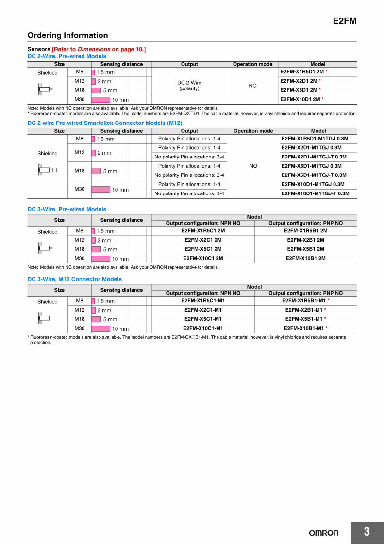
E2FMOrdering InformationSensors [Refer to Dimensions on page 10.]DC 2-Wire, Pre-wired Models
Note: Models with NC operation are also available. Ask your OMRON representative for details.* Fluororesin-coated models are also available. The model numbers are E2FM-QX@D1. The cable material, however, is vinyl chloride and requires separate protection.
DC 2-wire Pre-wired Smartclick Connector Models (M12)
DC 3-Wire, Pre-wired Models
Note: Models with NC operation are also available. Ask your OMRON representative for details.
DC 3-Wire, M12 Connector Models
* Fluororesin-coated models are also available. The model numbers are E2FM-QX@B1-M1. The cable material, however, is vinyl chloride and requires separate protection.
Size Sensing distance Output Operation mode Model
Shielded M8
DC 2-Wire(polarity) NO
E2FM-X1R5D1 2M *
M12 E2FM-X2D1 2M *
M18 E2FM-X5D1 2M *
M30 E2FM-X10D1 2M *
Size Sensing distance Output Operation mode Model
Shielded
M8 Polarity Pin allocations: 1-4
NO
E2FM-X1R5D1-M1TGJ 0.3M
M12Polarity Pin allocations: 1-4 E2FM-X2D1-M1TGJ 0.3M
No polarity Pin allocations: 3-4 E2FM-X2D1-M1TGJ-T 0.3M
M18Polarity Pin allocations: 1-4 E2FM-X5D1-M1TGJ 0.3M
No polarity Pin allocations: 3-4 E2FM-X5D1-M1TGJ-T 0.3M
M30Polarity Pin allocations: 1-4 E2FM-X10D1-M1TGJ 0.3M
No polarity Pin allocations: 3-4 E2FM-X10D1-M1TGJ-T 0.3M
Size Sensing distance ModelOutput configuration: NPN NO Output configuration: PNP NO
Shielded M8 E2FM-X1R5C1 2M E2FM-X1R5B1 2M
M12 E2FM-X2C1 2M E2FM-X2B1 2M
M18 E2FM-X5C1 2M E2FM-X5B1 2M
M30 E2FM-X10C1 2M E2FM-X10B1 2M
Size Sensing distance ModelOutput configuration: NPN NO Output configuration: PNP NO
Shielded M8 E2FM-X1R5C1-M1 E2FM-X1R5B1-M1 *
M12 E2FM-X2C1-M1 E2FM-X2B1-M1 *
M18 E2FM-X5C1-M1 E2FM-X5B1-M1 *
M30 E2FM-X10C1-M1 E2FM-X10B1-M1 *
1.5 mm
2 mm
5 mm
10 mm
1.5 mm
2 mm
5 mm
10 mm
1.5 mm
2 mm
5 mm
10 mm
1.5 mm
2 mm
5 mm
10 mm

E2FM
4
Accessories (Order Separately)Sensor I/O Connectors (M12, Sockets on One Cable End) (Models for Connectors and with Pre-wired Connectors: A Connector is not provided with the Sensor. Be sure to order a Connector separately.)[Refer to XS2, XS5.]
Note: Refer to Introduction to Sensor I/O Connectors for details.
Ratings and SpecificationsDC 2-Wire (E2FM-X@D@)
Appearance Cable length Sensor I/O Connector model number Applicable Proximity Sensor model number
2m XS2F-D421-DC0-F
E2FM-X@C1-M1E2FM-X@B1-M1
5m XS2F-D421-GC0-F
2m XS2F-D422-DC0-F
5m XS2F-D422-GC0-F
2m XS5F-D421-D80-FE2FM-X@D1-M1TGJE2FM-X@D1-M1TGJ-T
5m XS5F-D421-G80-F
Size M8 M12 M18 M30 M12 M18 M30
Shielded Shielded
Item Model E2FM-X1R5D1-@ E2FM-X2D1-@ E2FM-X5D1-@ E2FM-X10D1-@ E2FM-X2D1-M1T1GJ-T
E2FM-X5D1-M1T1GJ-T
E2FM-X10D1-M1T1GJ-T
Sensing distance 1.5 mm±10% 2 mm±10% 5 mm±10% 10 mm±10% 2 mm±10% 5 mm±10% 10 mm±10%
Set distance 0 to 1.05 mm 0 to 1.4 mm 0 to 3.5 mm 0 to 7 mm 0 to 1.4 mm 0 to 3.5 mm 0 to 7 mm
Differential travel 15% max. of sensing distance
Sensing object Ferrous metal (The sensing distance decreases with non-ferrous metal. Refer to Engineering Data on page 7.)
Standard sensing object Iron, 8 × 8 × 1 mm
Iron, 12 × 12 × 1 mm
Iron, 30 × 30 × 1 mm
Iron, 54 × 54 × 1 mm
Iron, 12 × 12 × 1 mm
Iron, 30 × 30 × 1 mm
Iron, 54 × 54 × 1 mm
Response frequency *1 200 Hz 100 Hz 100 Hz 50 Hz 100 Hz 100 Hz 50 Hz
Power supply voltage(operating voltage range) 12 to 24 VDC (10 to 30 VDC), ripple (p-p): 10% max.
Leakage current 0.8 mA max.
Output configuration With polarity No polarity
Control output
Switching capacity 3 to 100 mA
Residualvoltage
3 V max. (Load current: 100 mA max., Cable length: 2 m)
5 V max. (Load current: 100 mA max., Cable length: 2 m)
Indicators Operation indicator (red LED), Setting/Operation indicator (green LED)
Operation mode(with sensing object approaching)
NO *2
Protection circuits Surge suppressor, Load short-circuit protection
Ambient temperature range Operating/Storage: −25 to 70°C (with no icing or condensation)
Ambient humidity range Operating/Storage: 35% to 95% (with no condensation)
Temperature influence ±20% max. of sensing distance at 23°C in the temperature range of −25 to 70°C.
Voltage influence ±1% max. of sensing distance at rated voltage in the rated voltage ±15% range
Insulation resistance 50 MΩ min. (at 500 VDC) between current-carrying parts and case
Dielectric strength 1,000 VAC, 50/60 Hz for 1 minute between current-carrying parts and case
Vibration resistance Destruction: 10 to 55 Hz, 1.5-mm double amplitude for 2 hours each in X, Y, and Z directions
Shock resistance
Destruction: 500 m/s2
10 times each in X, Y, and Z directions
Destruction: 1,000 m/s2 10 times each in X, Y, and Z directions
Degree of protection IEC 60529 IP67
Connection method Unmarked: Pre-wired Models (Standard cable length: 2 m)Models ending with -M1GJ-@: Pre-wired Connector Models (Standard cable length: 300 mm)
Straight
L-shape
Smartclick Connector Relay Models (M12)

5
E2FM
*1. The response frequency of the DC switching section is an average value. Measurement conditions are as follows: standard sensing object, a distance of twice the standard sensing object, and a set distance of half the sensing distance.
*2. NC (normally closed) models are also available. Contact your OMRON representative.
Weight (packed state)
Pre-wired Models (2 m) Approx. 105 g Approx. 190 g Approx. 215 g Approx. 295 g --- --- ---
Pre-wired Connector Models
Approx. 65 g Approx. 85 g Approx. 110 g Approx. 190 g Approx. 85 g Approx. 110 g Approx. 190 g
Materi-als
Case Stainless steel (SUS303)
Sensing surface Stainless steel (SUS303)
(thickness) (0.4 mm) (0.8 mm) (0.8 mm)
Clamping nuts Stainless steel (SUS303)
Cable PVC (flame retardant)
Toothed washer Zinc-plated iron
Accessories Instruction manual
Size M8 M12 M18 M30 M12 M18 M30
Shielded Shielded
Item Model E2FM-X1R5D1-@ E2FM-X2D1-@ E2FM-X5D1-@ E2FM-X10D1-@ E2FM-X2D1-M1T1GJ-T
E2FM-X5D1-M1T1GJ-T
E2FM-X10D1-M1T1GJ-T

E2FM
6
DC 3-Wire (E2FM-X@C@, E2FM-X@B@)
*1. The response frequency of the DC switching section is an average value. Measurement conditions are as follows: standard sensing object, a distance of twice the standard sensing object, and a set distance of half the sensing distance.
*2. NC (normally closed) models are also available. Contact your OMRON representative.
Size M8 M12 M18 M30
Shielded Shielded
Item Model E2FM-X1R5@ E2FM-X2@ E2FM-X5@ E2FM-X10@
Sensing distance 1.5 mm±10% 2 mm±10% 5 mm±10% 10 mm±10%
Set distance 0 to 1.05 mm 0 to 1.4 mm 0 to 3.5 mm 0 to 7 mm
Differential travel 15% max. of sensing distance
Sensing object Ferrous metal (The sensing distance decreases with non-ferrous metal. Refer to Engineering Data on page 7.)
Standard sensing object Iron, 8 × 8 × 1 mm Iron, 12 × 12 × 1 mm Iron, 30 × 30 × 1 mm Iron, 54 × 54 × 1 mm
Response frequency *1 200 Hz 100 Hz 100 Hz 50 Hz
Power supply voltage(operating voltage range)
12 to 24 VDC (10 to 30 VDC), ripple (p-p): 10% max.
Current consumption 10 mA max.
Output configuration PNP open collector output
Control output
Switching ca-pacity 200 mA max.
Residualvoltage 2 V max. (Load current: 200 mA, Cable length: 2 m)
Indicators Operation indicator (yellow LED)
Operation mode(with sensing objectapproaching)
C1 Models: NPN open collector, NO (normally open) *2B1 Models: PNP open collector, NO (normally open) *2
Protection circuits Reversed power supply polarity protection, Surge suppressor, Load short-circuit protection, and Reversed output po-larity protection (except the E2FM-X1R5B1-M1)
Ambient temperature range Operating/Storage: −25 to 70°C (with no icing or condensation)
Ambient humidity range Operating/Storage: 35% to 95% (with no condensation)
Temperature influence ±20% max. of sensing distance at 23°C in the temperature range of −25 to 70°C.
Voltage influence ±1% max. of sensing distance in the rated voltage ±15% range (using the sensing distance at the rated voltage as standard)
Insulation resistance 50 MΩ min. (at 500 VDC) between current-carrying parts and case
Dielectric strength 1,000 VAC, 50/60 Hz for 1 minute between current-carrying parts and case
Vibration resistance Destruction: 10 to 55 Hz, 1.5-mm double amplitude for 2 hours each in X, Y, and Z directions
Shock resistanceDestruction: 500 m/s2
10 times each in X, Y, and Z directions
Destruction: 1,000 m/s2 10 times each in X, Y, and Z directions
Degree of protection IEC 60529 IP67
Connection method Unmarked: Pre-wired Models (Standard cable length: 2 m)Models ending with -M1: Connector Models
Weight (packed state)
Pre-wired Models (2 m) --- Approx. 170 g Approx. 190 g Approx. 275 g
Pre-wired Connector Models
Approx. 45 g Approx. 55 g Approx. 75 g Approx. 160 g
Materi-als
Case Stainless steel (SUS303)
Sensing sur-face Stainless steel (SUS303)
(thickness) (0.4 mm) (0.8 mm)
Clampingnuts Stainless steel (SUS303)
Toothedwasher Zinc-plated iron
Accessories Instruction manual

7
E2FMEngineering Data (Reference Value)
Sensing Area Influence of Sensing Object Size and MaterialE2FM-X@ E2FM-X1R5@ E2FM-X2@
Leakage CurrentE2FM-X5@ E2FM-X10@ E2FM-X@D1-M1TGJ (-T)
Residual Output VoltageE2FM-X@C@/B@ E2FM-X@D1-M1TGJ (-T)
E2FM-X2D@
E2FM-X10@
E2FM-X1R5@
12
10
8
6
4
2
0
E2FM-X5@
Dis
tanc
e X
(m
m)
−25 −15−20 −10 −5 0 5 10 15 20 25Distance Y (mm)
2.5
2.0
1.5
1.0
0.5
0.00 5 10 15 20 25
Dis
tanc
e X
(m
m)
Stainlesssteel(SUS304)
Aluminum
Brass
Copper
Iron
Side length of sensing object: d (mm)
3.0
2.5
2.0
1.5
1.0
0.5
0.00 10 15 20 25 30 355
Dis
tanc
e X
(m
m)
Iron
AluminumBrass
Copper
Stainlesssteel(SUS304)
Side length of sensing object: d (mm)
7
6
5
4
3
2
1
00 20 40 60 80
Dis
tanc
e X
(m
m)
Stainlesssteel(SUS304)
Iron
Brass
AluminumCopper
Side length of sensing object: d (mm)
12
10
8
6
4
2
00 10 20 30 40 50 60 80 9070
Dis
tanc
e X
(m
m)
Side length of sensing object: d (mm)
Stainlesssteel(SUS304)
Iron
Brass
Aluminum
Copper
E2FM-X10D1-M1TGJ(-T)
E2FM-X5D1-M1GJ(-T)
E2FM-X2D1-M1TGJ(-T)
E2FM-X1R5D1-@
1.0
0.8
0.6
0.4
0.2
0.00 5 10 15 20 25 30
Leak
age
curr
ent (
mA
)
Power supply voltage (V)
2
1.5
1
0.5
01 10 50 100 200 1,000
E2FM-X1R5@
E2FM-X2@E2FM-X5@E2FM-X10@
Res
idua
l out
put v
olta
ge (
V)
Load current (mA)
5
4
3
2
1
01 3 5 1 0 30 50 100
E2FM-X@D1-M1TGJ-T
E2FM-X@D1-@
Res
idua
l out
put v
olta
ge (
V)
Load current (mA)

E2FM
8
I/O Circuit DiagramsDC 2-Wire Models
DC 3-Wire Models
Operationmode Model Timing chart Output circuit
NO
E2FM-X@D1-@
E2FM-X@D1-M1TGJ-T
Opera-tion
mode
Output config-uration
Model Timing chart Output circuit
NO
NPNopen-
collector model
E2FM-X1R5C@E2FM-X2C@E2FM-X5C@E2FM-X10C@
PNPopen-
collector model
E2FM-X1R5B@E2FM-X2B@E2FM-X5B@E2FM-X10B@
100 0
Non-sensing area
Sensing object
Unstable sensing area
Set position
Stable sensing area
Proximity sensor
Rated sensing distance
ON
ON
OFF
OFF
ON
OFF
Setting indicator (green)
Operation indicator (red)
Controloutput
(%) 70 (TYP)
0 V
1
4
Proximity sensor main circuit
Note: The load can be connected to either the +V or 0 V side.
Load12 to 24 VDC
Connector Pin Arrangement
Note: Pins 2 and 3 are not used.
Brown
Blue
0V
Load12 to 24VDC
Note1. The load can be connected to either the +V or 0 V side.
4
3
Proximity sensor main circuit
Note: Pins 1 and 2 are not used.
Connector Pin Arrangement
2. The E2FM-X@@1-M1TGJ-T has no polarity. There is no need to be concerned about the polarity of pins 3 and 4.
100 0
Non-sensing area Sensing area
Sensing object
Rated sensing distance
Proximity sensor
ON
OFF
ON
OFF
Operation indicator (yellow)
Controloutput
(%)
*
0 V
Proximity sensor
maincircuit
+V
Load
Connector Pin Arrangement
Note: For Connector Models, theconnection between pins 1, 4 and 3uses an NO contact, and theconnection between pins 1, 2 and 3uses an NC contact.
Brown
Black
Blue
* There is no reversed output polarity protection diode.
0 V
Proximity sensor
maincircuit
DC12 to 24VDC
Load
Connector Pin Arrangement
Note: For Connector Models, theconnection between pins 1, 4 and 3uses an NO contact, and theconnection between pins 1, 2 and 3uses an NC contact.
Brown
Black
Blue
* There is no reversed output polarity protection diode.
*

E2FM
9
Safety Precautions
This product is not designed or rated for ensuring safety of persons. Do not use it for such purposes.
Never use this product with an AC power supply. Otherwise, explosion may result.
The following precautions must be observed to ensure safe operation.1. Do not use the Sensor in an environment where inflammable or
explosive gas is present.2. Do not attempt to disassemble, repair, or modify any Sensors.3. Power Supply Voltage
Do not use a voltage that exceeds the rated operating voltage range. Applying a voltage that is higher than the operating voltage range may result in explosion or fire.
4. Incorrect WiringBe sure that the power supply polarity and other wiring is correct. Incorrect wiring may cause explosion or fire.
5. Connection without a LoadIf the power supply is connected directly without a load, the internal elements may explode or burn. Be sure to insert a load when connecting the power supply.
Do not use the Sensor under ambient conditions that exceed the ratings.1. Do not use the Sensor in the following locations.
(1) Outdoor locations directly subject to sunlight, rain, snow, or water droplets
(2) Locations subject to atmospheres with chemical vapors, in particular solvents and acids
(3) Locations subject to corrosive gas2. The Sensor may malfunction if used near ultrasonic cleaning
equipment, high-frequency equipment, transceivers, cellular phones, inverters, or other devices that generate a high-frequency electric field. Refer to the Technical Guide Photoelectric Sensors for typical measures.
3. Laying the Sensor wiring in the same conduit or duct as high-voltage wires or power lines may result in incorrect operation and damage due to induction. Wire the Sensor using a separate conduit or independent conduit.
4. CleaningNever use thinner or other solvents. Otherwise, the Sensor surface may be dissolved.
● DesignInfluence of Surrounding MetalWhen the Proximity Sensor is embedded in metal, make sure that the clearances given in the following table are maintained. The values depend on the type of nuts used for mounting. Be sure to use the supplied nuts (SUS303).
(Unit: mm)
Note: The influence from other non-magnetic surrounding metals is nearly the same as that from aluminum.
Mutual InterferenceWhen installing two or more Sensors face-to-face or side-by-side, ensure that the minimum distances given in the following table are maintained.
Chips from Cutting AluminumNormally, chips from cutting aluminum or cast iron will not cause a detection signal to be output even if it adheres to or accumulates on the detection surface. In the following cases, however, a detection signal may be output. Remove the cutting chips in these cases.
● MountingDo not tighten the nut with excessive force. A washer must be used with the nut. Do not use tightening force that exceeds the values in the following table.
WARNING
Precautions for Safe Use
Precautions for Correct Use
l
D
d dia.
l
mn
Iteml d D m n
Model Embeddingmaterial
E2FM-X1R5@Iron 0 8 0 4.5 30
Aluminum 10 50 10 4.5 50
E2FM-X2@Iron 0 12 0 8 40
Aluminum 16 70 16 8 70
E2FM-X5@Iron 0 18 0 20 60
Aluminum 16 80 16 20 80
E2FM-X10@Iron 0 30 0 40 100
Aluminum 24 120 24 40 120
A
B
(Unit: mm)
Model Item A BE2FM-X1R5@ 35 30E2FM-X2@ 40 35E2FM-X5@ 65 60E2FM-X10@ 110 100
1. If d ≥ D at the center of the detection surface where d is the cutting chip size and D is the detection surface size
2. If the cutting chips are pressed down
Model Dimension(mm) D
E2FM-X1R5@ 6E2FM-X2@ 10E2FM-X5@ 16E2FM-X10@ 28
23 d
D Detection surface
Cutting chip
Cutting chips
Pressed down
Model TorqueE2FM-X1R5@ 9 N·mE2FM-X2@ 30 N·mE2FM-X5@ 70 N·mE2FM-X10@ 180 N·m

E2FM
10
Dimensions
SensorsPre-wired Models
Pre-wired Connector Models
(Unit: mm)Tolerance class IT16 applies to dimensions in this data sheet unless otherwise specified.
25
49
M8 × 113
4 5
30
15 dia.
Two clamping nuts
Operation indicators
* 4-dia. vinyl-insulated round cable with 2 conductors(Conductor cross section: 0.2 mm2, Insulator diameter: 1.4 mm)4-dia. vinyl-insulated round cable with 3 conductors(Conductor cross section: 0.2 mm2, Insulator diameter: 1.2 mm)
4-dia. vinyl-insulated round cable (flame retardant), Standard length; 2 m *
Toothed washer
E2FM-X1R5@
33
53
M12 × 117
4 7
39
21 dia.
Two clamping nuts Operation indicators
* 6-dia. vinyl-insulated round cable with 2 conductors(Conductor cross section: 0.5 mm2, Insulator diameter: 1.75 mm)6-dia. vinyl-insulated round cable with 3 conductors(Conductor cross section: 0.5 mm2, Insulator diameter: 1.75 mm)
6-dia. vinyl-insulated round cable (flame retardant), Standard length; 2 m *
Toothed washer
E2FM-X2@
36
56
M18 ´ 124
410
42
29 dia.
Two clamping nuts Operation indicators
* 6-dia. vinyl-insulated round cable with 2 conductors(Conductor cross section: 0.5 mm2, Insulator diameter: 1.75 mm)6-dia. vinyl-insulated round cable with 3 conductors(Conductor cross section: 0.5 mm2, Insulator diameter: 1.75 mm)
6-dia. vinyl-insulated round cable (flame retardant), Standard length; 2 m *
Toothed washer
E2FM-X5@
43
63.5
M30 ´ 1.536
5 10
49
42 dia.
Two clamping nuts
Operation indicators
* 6-dia. vinyl-insulated round cable with 2 conductors(Conductor cross section: 0.5 mm2, Insulator diameter: 1.75 mm)6-dia. vinyl-insulated round cable with 3 conductors(Conductor cross section: 0.5 mm2, Insulator diameter: 1.75 mm)
6-dia. vinyl-insulated round cable (flame retardant), Standard length; 2 m *
Toothed washer
E2FM-X10@
Toothed washer
*1
25
49
M8 × 1
M12 × 1
13
4 5
30
15 dia.
Two clamping nuts
Indicator *2
*1. 4-dia. vinyl-insulated round cable (flame retardant), Standard length; 300 mm*2. Operation indicator (red/green)
Setting indicator (green)
E2FM-X1R5D@-M1TGJ-@
17
4 733
53
39
21 dia.
Two clamping nuts
Toothed washer Indicator *2
*1. 6-dia. vinyl-insulated round cable (flame retardant), Standard length; 300 mm*2. Operation indicator (red/green)
Setting indicator (green)
M12 ´ 1
*1M12 ´ 1
E2FM-X2D@-M1TGJ-@
24
36
42
56
410
M18 ´ 1
29 dia.
Two clamping nuts
Toothed washer Indicator *2 *1
M12 ´ 1
*1. 6-dia. vinyl-insulated round cable (flame retardant), Standard length; 300 mm*2. Operation indicator (red/green)
Setting indicator (green)
E2FM-X5D@-M1TGJ-@
36
63.5
49
43
5 10
M30 ´ 1.5
42 dia.
Toothed washer
Two clamping nuts
Indicator *2*1
M12 ´ 1
*1. 6-dia. vinyl-insulated round cable (flame retardant), Standard length; 300 mm*2. Operation indicator (red/green)
Setting indicator (green)
E2FM-X10D@-M1TGJ-@

11
E2FM
M12 Connector Models
4 5
13
25
30
34.5
53.5
15 dia.
Two clamping nuts
Toothed washerFour operation indicators (yellow)
M12 × 1M8 × 1
E2FM-X1R5@@-M1
17
53
39
33
4 721 dia.
Two clamping nuts
Toothed washer
M12 × 1
Four operation indicators (yellow)
M12 × 1
E2FM-X2@@-M1
24
10
56
42
36
429 dia.
M18 × 1Two clamping nuts
Toothed washer
M12 × 1
Four operation indicators (yellow)
E2FM-X5@@-M163.5
49
43
510
36
42 dia.
Two clamping nuts
Toothed washer
Four operation indicators (yellow)M30 × 1.5
M12 × 1
E2FM-X10@@-M1
F
Mounting Hole Dimensions
Dimension M8 M12 M18 M30F (mm) 8.5 dia. 12.5 dia. 18.5 dia. 30.5 dia.+0.5
0+0.5 0
+0.5 0
+0.5 0

Terms and Conditions Agreement Read and understand this catalog. Please read and understand this catalog before purchasing the products. Please consult your OMRON representative if you have any questions or comments. Warranties. (a) Exclusive Warranty. Omron’s exclusive warranty is that the Products will be free from defects in materials and workmanship for a period of twelve months from the date of sale by Omron (or such other period expressed in writing by Omron). Omron disclaims all other warranties, express or implied. (b) Limitations. OMRON MAKES NO WARRANTY OR REPRESENTATION, EXPRESS OR IMPLIED, ABOUT NON-INFRINGEMENT, MERCHANTABILITY OR FITNESS FOR A PARTICULAR PURPOSE OF THE PRODUCTS. BUYER ACKNOWLEDGES THAT IT ALONE HAS DETERMINED THAT THE PRODUCTS WILL SUITABLY MEET THE REQUIREMENTS OF THEIR INTENDED USE. Omron further disclaims all warranties and responsibility of any type for claims or expenses based on infringement by the Products or otherwise of any intellectual property right. (c) Buyer Remedy. Omron’s sole obligation hereunder shall be, at Omron’s election, to (i) replace (in the form originally shipped with Buyer responsible for labor charges for removal or replacement thereof) the non-complying Product, (ii) repair the non-complying Product, or (iii) repay or credit Buyer an amount equal to the purchase price of the non-complying Product; provided that in no event shall Omron be responsible for warranty, repair, indemnity or any other claims or expenses regarding the Products unless Omron’s analysis confirms that the Products were properly handled, stored, installed and maintained and not subject to contamination, abuse, misuse or inappropriate modification. Return of any Products by Buyer must be approved in writing by Omron before shipment. Omron Companies shall not be liable for the suitability or unsuitability or the results from the use of Products in combination with any electrical or electronic components, circuits, system assemblies or any other materials or substances or environments. Any advice, recommendations or information given orally or in writing, are not to be construed as an amendment or addition to the above warranty. See http://www.omron.com/global/ or contact your Omron representative for published information. Limitation on Liability; Etc. OMRON COMPANIES SHALL NOT BE LIABLE FOR SPECIAL, INDIRECT, INCIDENTAL, OR CONSEQUENTIAL DAMAGES, LOSS OF PROFITS OR PRODUCTION OR COMMERCIAL LOSS IN ANY WAY CONNECTED WITH THE PRODUCTS, WHETHER SUCH CLAIM IS BASED IN CONTRACT, WARRANTY, NEGLIGENCE OR STRICT LIABILITY. Further, in no event shall liability of Omron Companies exceed the individual price of the Product on which liability is asserted. Suitability of Use. Omron Companies shall not be responsible for conformity with any standards, codes or regulations which apply to the combination of the Product in the Buyer’s application or use of the Product. At Buyer’s request, Omron will provide applicable third party certification documents identifying ratings and limitations of use which apply to the Product. This information by itself is not sufficient for a complete determination of the suitability of the Product in combination with the end product, machine, system, or other application or use. Buyer shall be solely responsible for determining appropriateness of the particular Product with respect to Buyer’s application, product or system. Buyer shall take application responsibility in all cases. NEVER USE THE PRODUCT FOR AN APPLICATION INVOLVING SERIOUS RISK TO LIFE OR PROPERTY OR IN LARGE QUANTITIES WITHOUT ENSURING THAT THE SYSTEM AS A WHOLE HAS BEEN DESIGNED TO ADDRESS THE RISKS, AND THAT THE OMRON PRODUCT(S) IS PROPERLY RATED AND INSTALLED FOR THE INTENDED USE WITHIN THE OVERALL EQUIPMENT OR SYSTEM. Programmable Products. Omron Companies shall not be responsible for the user’s programming of a programmable Product, or any consequence thereof. Performance Data. Data presented in Omron Company websites, catalogs and other materials is provided as a guide for the user in determining suitability and does not constitute a warranty. It may represent the result of Omron’s test conditions, and the user must correlate it to actual application requirements. Actual performance is subject to the Omron’s Warranty and Limitations of Liability. Change in Specifications. Product specifications and accessories may be changed at any time based on improvements and other reasons. It is our practice to change part numbers when published ratings or features are changed, or when significant construction changes are made. However, some specifications of the Product may be changed without any notice. When in doubt, special part numbers may be assigned to fix or establish key specifications for your application. Please consult with your Omron’s representative at any time to confirm actual specifications of purchased Product. Errors and Omissions. Information presented by Omron Companies has been checked and is believed to be accurate; however, no responsibility is assumed for clerical, typographical or proofreading errors or omissions.
2017.2
In the interest of product improvement, specifications are subject to change without notice.
OMRON Corporation Industrial Automation Company http://www.ia.omron.com/
(c)Copyright OMRON Corporation 2017 All Right Reserved.