Embed Size (px)
Citation preview

ProView™ PVR 6000 Series
Professional Integrated Receiver Decoders
Version 4.1 Part Number: MAN-PVR6000-4.1 Revision A © Harmonic Inc. 2006 ALL RIGHTS RESERVED

User Manual
© 2006 Harmonic Inc. All rights reserved. Harmonic reserves the right to alter the equipment specifications and descriptions in this publication without prior notice. No part of this publication shall be deemed to be part of any contract or warranty unless specifically incorporated by reference into such contract or warranty. The information contained herein is merely descriptive in nature, and does not constitute a binding offer for sale of the product described herein. Harmonic assumes no responsibility or liability arising from the use of the products described herein, except as expressly agreed to in writing by Harmonic. The use and purchase of this product does not convey a license under any patent rights, copyrights, trademark rights, or any intellectual property rights of Harmonic. Nothing hereunder constitutes a representation or warranty that using any products in the manner described herein will not infringe any patents of third parties. File ProView™ PVR 6000 User Rev 4.1

PVR 6000 Series
Professional Integrated Receiver Decoders
Page i
INTRODUCTION Harmonic Inc. takes great pride in delivery of its products and makes every endeavor to
ensure its clients full satisfaction.
On behalf of the whole Harmonic team, we would like to extend our congratulations on
your investment in the ProView™ PVR 6000 series of Professional Integrated Receiver
Decoders.
MANUAL SCOPE AND STRUCTURE
The ProView™ PVR 6000 series Professional Integrated Receiver Decoders user manual is
comprised of the following main sections:
1. OVERVIEW:
This section provides the introduction and product description, including: highlights, benefits and typical applications, a functional and physical description of the unit, and its main capabilities and specifications.
2. INSTALLATION:
This section provides information and procedures required to install and activate the unit. The procedures include: site preparation and requirements, installation in a 19" rack, cable connections, rear panel options and pin-out descriptions, initial settings, and serviceability check.
3. OPERATION:
This section provides information on the operation of the unit, as well as data and instructions on using the unit and operating the control and monitoring functions.
4. APPENDIXES
This section provides information on software loading and downloading.
TECHNICAL SUPPORT
In case of technical problems with the IRD or one of its components, refer to the System
Documentation. Usually, this may assist you to resolve most technical difficulties.
Call your local distributor for technical support should you be unable to resolve the
problem.
User Manual
Overview
Page ii (Rev. 4.1/ SW v1.60/ December 2006)
HOW TO RETURN FAULTY PARTS
Before Returning An Item: • Request an RMA (Return Merchandise Authorization) Tracking Number from
your local distributor. • Harmonic Support will assign an RMA Tracking Number; this must accompany
the item being returned and will be referred to in all correspondence. • Send the item to Harmonic with the RMA Number included in the accompanying
documentation (shipping and customs forms).
Customer Support Contact Information Harmonic Inc.
549 Baltic Way Sunnyvale, California 94089 +1.408.542.2500 USA +1.800.788.1330 FAX +1.408.542.2510 http://www.harmonicinc.com Email: [email protected]

PVR 6000 Series
Professional Integrated Receiver Decoders
Page iii
Warranty
Harmonic warrants that the hardware (a tangible device or component thereof, including any embedded code or firmware required for such device to function on a stand-alone basis), purchased under Harmonic’s sales terms and conditions will be free from defects of material and workmanship under normal use and service as follows: (i) For a period of one (1) year following shipment by Harmonic, Harmonic will supply, at no charge and at Harmonic’s option, either new or refurbished replacement parts for defect parts of the products or new or refurbished products to replace defective products; and (ii) For a period of one (1) year following shipment by Harmonic, Harmonic will pay the labour charges incurred by Harmonic to repair defective products. You are responsible for any labour charges incurred following such one (1) year period. This warranty will not apply to any products which have been repaired or altered other than by Harmonic, your failure to meet environmental specifications, or products which have been subjected to misuse, negligence, accident, unusual physical or electrical stress, or other causes other than the normal and intended use of the products. THE WARRANTY FOR THE PRODUCTS AS SET FORTH HEREIN IS IN LIEU OF, AND HARMONIC HEREBY DISCLAIMS, ALL OTHER WARRANTIES EXPRESSED, STATUTORY OR IMPLIED, WHETHER ORAL OR WRITTEN, INCLUDING THE IMPLIED WARRANTIES OF MERCHANTABILITY AND FITNESS FOR A PARTICULAR PURPOSE.
COMPLIANCE EMC SAFETY
EN55022 (CISPR 22) EN60950
EN55024 (CISPR 24) CB (IEC60950)
EN55013 (CISPR 13) UL60950
EN55020 (CISPR 20) cTUVus
FCC part 15 (class B)
CB

User Manual
Overview
Page iv (Rev. 4.1/ SW v1.60/ December 2006)
CE Certification
The ProView™ PVR 6000 meets all the CE Class A requirements.
In order to meet CE requirements, appropriate cables must be connected on all ASI outputs (when
applicable). When cables are connected to these outputs then the device is compliant with the use of
FAIR-RITE 0443164151.
FCC Compliance Notice
Trade Name Harmonic
Product Name Integrated Receiver Decoder
Product Model Number ProView™ PVR 6000 Series
These devices comply with Part 15 of the FCC Rules.
OPERATION IS SUBJECT TO THE FOLLOWING TWO CONDITIONS:
These devices may not cause harmful interference.
These devices must accept any interference received, including interference that
may cause undesired operation.
The FCC Wants You to Know This equipment has been tested and found to comply with the limits for a Class A digital device, pursuant to Part 15 of the FCC rules. These limits are designed to provide reasonable protection against harmful interference when the equipment is operated in a commercial environment.
This equipment generates, uses and can radiate radio frequency energy and, if not installed and used in accordance with the instructions, may cause harmful interference to radio communications.
Operation of this equipment in a residential area is likely to cause harmful interference, in which case the user will be required to correct the interference at his expense.
FCC Warning Modifications not expressly approved by the manufacturer could void the user authority to operate the equipment under FCC Rules.

PVR 6000 Series
Professional Integrated Receiver Decoders
Page v
WEEE/ROHS COMPLIANCE POLICY
Harmonic Inc. intends to fully comply with the European Union’s Directive
2002/96/EC as amended by Directive 2003/108/EC, on Waste Electrical
and Electronic Equipment, also known as “WEEE,” and Directive
2002/95/EC, as amended, on the Restriction of use of Hazardous
Substances, also known as “RoHS.”
Harmonic will ensure that product which cannot be re-used will be recycled
in compliance with the WEEE Directive. To that end, users are advised that
(1) Harmonic equipment is not to be discarded in household or office
garbage, (2) Harmonic Inc. will pay the freight for shipment of equipment
to be disposed of if it is returned to Harmonic, (3) customers should call
the normal RMA telephone numbers to arrange for such shipment, and (4)
customers may consult the Harmonic website
(http://harmonicinc.com/ah_weee_recycle.cfm) for additional and updated
information on this process.
Harmonic will ensure that its products will either be re-used or recycled in
compliance with the WEEE Directive. For the latest information concerning
Harmonic’s WEEE/RoHS Compliance Policy and its Recycling and Take-Back
process, please visit our website.

User Manual
Overview
Page vi (Rev. 4.1/ SW v1.60/ December 2006)
TABLE OF CONTENTS Chapter 1. Overview........................................................ 1-1
1.1. General Information......................................................... 1-1 1.2. Highlights and Benefits..................................................... 1-2 1.3. Applications .................................................................... 1-3 1.4. Functionality ................................................................... 1-4 1.5. Mechanical Structure........................................................ 1-5
1.5.1. Front Panel ..................................................................... 1-5 1.5.2. Various Front-Ends .......................................................... 1-6 1.5.3. Software Permission (Licensing) ........................................ 1-7 1.5.4. PVR 6000 models ............................................................ 1-8
1.6. Management................................................................. 1-18 1.6.1. Local Management......................................................... 1-18 1.6.2. Remote Management ..................................................... 1-18
1.7. Characteristics and Specifications..................................... 1-19 1.7.1. Transport Stream Interface Options ................................. 1-19 1.7.2. Advanced Processing...................................................... 1-22 1.7.3. Decoder Outputs ........................................................... 1-23 1.7.4. Conditional Access ......................................................... 1-25 1.7.5. Control and Monitoring ................................................... 1-25 1.7.6. Compliance................................................................... 1-26 1.7.7. Environmental Conditions ............................................... 1-26 1.7.8. Physical and Power Specifications .................................... 1-27
Chapter 2. Installation .................................................... 2-1 2.1. Safety Precautions........................................................... 2-1 2.2. Inventory Check.............................................................. 2-1 2.3. Installation Instructions.................................................... 2-2
2.3.1. Site Preparation .............................................................. 2-2 2.3.2. Mechanical Rack Installation.............................................. 2-2 2.3.3. Insertion of the DVB-CI Module (PCMCIA) ........................... 2-8
2.4. Cable Connection............................................................. 2-9 2.5. Initialization And Configuration ........................................ 2-13
2.5.1. Electrical Power Connection............................................. 2-13 2.5.2. Powering Up ................................................................. 2-14 2.5.3. Tuning ......................................................................... 2-14 2.5.4. Performing Serviceability Check....................................... 2-15
Chapter 3. PVR 6000 Control Interfaces.......................... 3-1 3.1. Front Panel Control Interface............................................. 3-1
3.1.1. Controls and Displays....................................................... 3-1 3.1.2. PVR 6000 Front Panel Screen Types ................................... 3-2 3.1.3. PVR 6000 Menu Tree........................................................ 3-8 3.1.4. Front Panel Initialization Sequence..................................... 3-9

PVR 6000 Series
Professional Integrated Receiver Decoders
Page vii
3.2. Web Management Interface............................................. 3-10 Chapter 4. Operation and Management ...........................4-1
4.1. Preset Menu ....................................................................4-1 4.2. Configuration ..................................................................4-1
4.2.1. Receiver Modules .............................................................4-2 4.2.2. Satellite Receiver Modules .................................................4-3 4.2.3. Stream Configuration Menu ............................................. 4-39 4.2.4. Filtering........................................................................ 4-46 4.2.5. Service Configuration Menu ............................................. 4-57 4.2.6. Video Configuration Menu................................................ 4-75 4.2.7. Audio Configuration Menu ............................................... 4-99 4.2.8. Data Configuration Menu............................................... 4-109 4.2.9. Conditional Access Configuration Menu............................ 4-120 4.2.10. Unit Configuration Menu................................................ 4-127
4.3. Status ........................................................................ 4-144 4.3.1. Receiver Status ........................................................... 4-145 4.3.2. Stream Status Menu..................................................... 4-152 4.3.3. Service Status ............................................................. 4-154 4.3.4. Video Status Menu ....................................................... 4-154 4.3.5. Audio Status Menu ....................................................... 4-158 4.3.6. Data Status Menu ........................................................ 4-160 4.3.7. Conditional Access Status Menu ..................................... 4-162 4.3.8. Unit Status Menu ......................................................... 4-165
APPENDIX Appendix A Software Download ..........................................................A-1 Appendix B IP-Front End Software Upgrade Procedure ...........................B-1 Appendix C Aspect Ratio Configuration Process .....................................C-1 Appendix D Warning Messages .......................................................... D-1

User Manual
Overview
Page viii (Rev. 4.1/ SW v1.60/ December 2006)
LIST OF FIGURES Figure 1-1: Signal Path in the PVR 6000 – Functionality Block Diagram...... 1-4 Figure 1-2: PVR 6000 Unit................................................................... 1-5 Figure 1-3: Front View of the IRD......................................................... 1-5 Figure 1-4: PVR 6010 Rear Panel (IP Input interface) .............................. 1-6 Figure 1-5: PVR 6010 Rear Panel (DVB-S Dual Input interface)................. 1-6 Figure 1-6: PVR 6010 Rear Panel (Decoder Only interface)....................... 1-7 Figure 1-7: PVR 6000 Rear Panel (Standard)......................................... 1-8 Figure 1-8: PVR 6010 Rear Panel.......................................................... 1-9 Figure 1-9: PVR 6020 Rear Panel........................................................1-10 Figure 1-10: PVR 6030 Rear Panel........................................................1-11 Figure 1-11: PVR 6040 Rear Panel........................................................1-12 Figure 1-12: PVR 6050 Rear Panel.........................................................1-13 Figure 1-13: PVR 6060 Rear Panel........................................................1-15 Figure 1-14: PVR 6070 Rear Panel........................................................1-16 Figure 1-15: PVR 6080 Rear Panel........................................................1-17 Figure 2-1: Pair of Rack Slides ............................................................. 2-3 Figure 2-2: Rack Slide Measurement Specifications ................................. 2-4 Figure 2-3: Laying the Device on the Rack-Slides ................................... 2-5 Figure 2-4: Clipped Mounting Brackets .................................................. 2-5 Figure 2-5: Device Mounted on a Pair of Rack-Slides ............................... 2-6 Figure 2-6: Multiple Devices Mounted on a Single Pair of Rack-Slides......... 2-7 Figure 2-7: DVB-CI Module.................................................................. 2-8 Figure 2-8: PVR 6080 Rear Panel......................................................... 2-9 Figure 2-9: 9-Pin Male Connector Pin Numbering ...................................2-10 Figure 2-10: Power Supply Configurations and Rack-Mount Grounding Jackscrew
......................................................................................2-13 Figure 3-1: Front Panel ....................................................................... 3-1 Figure 3-2: PVR 6000 Front Panel Menu (Root Menu) - Basic Structure ...... 3-8 Figure 3-3: PVR 6000 Web Management access box...............................3-10 Figure 3-4: PVR 6000 Web Management Interface Screen (Example)........3-11 Figure 4-1: PVR 6000 Configuration Main Menu ...................................... 4-2 Figure 4-2: DVB-S Receiver Parameters Menu Screen ............................. 4-4 Figure 4-3: DVB-S2 Receiver Parameters Menu Screen...........................4-12 Figure 4-4: DVB-DSNG Receiver Parameters Menu Screen ......................4-21 Figure 4-5: DVB-IP Receiver – MPEGoIP 1 Parameters Menu Screen .........4-29 Figure 4-6: DVB-IP Receiver – General Parameters Menu Screen .............4-35 Figure 4-7: Stream Configuration Menu................................................4-39 Figure 4-8: Stream Parameters Menu Screen ........................................4-40 Figure 4-9: General Filtering Parameters Menu Screen ...........................4-48

PVR 6000 Series
Professional Integrated Receiver Decoders
Page ix
Figure 4-10: Select Services Menu Screen ............................................. 4-52 Figure 4-11: Select PIDs Menu Screen .................................................. 4-55 Figure 4-12: Service Configuration Menu ............................................... 4-57 Figure 4-13: TV1 Menu Screen............................................................. 4-60 Figure 4-14: Preferred Language Screen................................................ 4-64 Figure 4-15: PID Select Menu Screen.................................................... 4-68 Figure 4-16: Port to Service Menu Screen.............................................. 4-71 Figure 4-17: General Service Menu Screen ............................................ 4-73 Figure 4-18: Video Configuration Menu.................................................. 4-75 Figure 4-19: Video 1 Menu Screen........................................................ 4-78 Figure 4-20: VBI 1 Parameters............................................................. 4-85 Figure 4-21: OSD1 Menu Screen .......................................................... 4-95 Figure 4-22: Audio Configuration Menu ................................................. 4-99 Figure 4-23: Audio 1 Menu Screen...................................................... 4-102 Figure 4-24: Data Configuration Menu................................................. 4-109 Figure 4-25: IP DATA PORT Menu Screen............................................. 4-114 Figure 4-26: Conditional Access Configuration Menu.............................. 4-120 Figure 4-27: Unit Configuration Menu.................................................. 4-127 Figure 4-28: Unit General Screen ....................................................... 4-130 Figure 4-29: Change Password Screen ................................................ 4-131 Figure 4-30: Unit Serial Screen .......................................................... 4-132 Figure 4-31: Unit Ethernet Screen ...................................................... 4-135 Figure 4-32: PVR 6000 Licensing Screen.............................................. 4-137 Figure 4-33: PVR 6000 Dry Contact Screen.......................................... 4-138 Figure 4-34: PVR 6000 Status Screen ................................................. 4-145 Figure 4-35: PVR 6000 DVBS Status Screen......................................... 4-146 Figure 4-36: PVR 6000 DVBS2 Status Screen ....................................... 4-148 Figure 4-37: PVR 6000 DVB IP Status Screen....................................... 4-149 Figure 4-38: PVR 6000 Stream Status Screen ...................................... 4-152 Figure 4-39: PVR 6000 Service Status Screen ...................................... 4-154 Figure 4-40: PVR 6000 Video Status Screen......................................... 4-155 Figure 4-41: PVR 6000 Audio Status Screen......................................... 4-158 Figure 4-42: PVR 6000 IP Data Port Status Screen................................ 4-161 Figure 4-43: PVR 6000 Unit Status Screen........................................... 4-165 Figure 4-44: Unit – Identity (Status Screen) ........................................ 4-166 Figure 4-45: Unit – Versions (Status Screen) ....................................... 4-166 Figure A-1: Start Menu – Select Run .....................................................A-2 Figure A-2: Run Dialog Box..................................................................A-3 Figure A-3: Open FTP Session ..............................................................A-3 Figure A-4: Login to FTP ......................................................................A-4 Figure A-5: Access Bin Folder ...............................................................A-4 Figure A-6: Loading the File .................................................................A-5 Figure A-7: Start Menu – Open HyperTerminal........................................A-8

User Manual
Overview
Page x (Rev. 4.1/ SW v1.60/ December 2006)
Figure A-8: HyperTerminal – Enter Connection ....................................... A-9 Figure A-9: Select PC COM Port............................................................ A-9 Figure A-10: Port Settings Tab............................................................. A-10 Figure A-11: HyperTerminal Window..................................................... A-11 Figure A-12: Update Software Version Command ................................... A-12 Figure A-13: Erasing Flash Process ....................................................... A-13 Figure A-14: Ready to Receive New Software......................................... A-14 Figure A-15: Send File Dialog Box ........................................................ A-15 Figure A-16: Sending Status Dialog Box ................................................ A-15 Figure A-17: IRD Boot Application Starts ............................................... A-16 Figure A-18: Complete Software Loading............................................... A-17 Figure C-1: Aspect Ratio Conversion Machine ......................................... C-1 Figure C-2: Normal 4:3 Aspect Ratio..................................................... C-3 Figure C-3: Normal 16:9 Aspect Ratio ................................................... C-3 Figure D-1: Front panel warning LEDs ...................................................D-2

PVR 6000 Series
Professional Integrated Receiver Decoders
Page xi
LIST OF TABLES Table 2-1: PVR 6000 Rear Panel – Connectors and Cables....................... 2-9 Table 2-2: RS-232/RS-485 Control Connector Pin-Out .......................... 2-11 Table 2-3: RS-232 Low Speed Data and GPI Pin-Out ............................ 2-11 Table 2-4: RS-422 High Speed Data Pin-Out ....................................... 2-11 Table 2-5: Audio 3-4 Breakout Cable Pin-Out (Harmonic Inc. P/N 204346)2-12 Table 2-6: AES/EBU Balanced Breakout Cable Pin-Out (Harmonic Inc.
P/N 204345) ..................................................................... 2-12 Table 2-7: PVR 6000 Serviceability Check .......................................... 2-15 Table 3-1: PVR 6000 Web Management Interface ................................ 3-11 Table 4-1: Band Frequency Range .......................................................4-5 Table 4-2: Band Frequency Designations ............................................ 4-13 Table 4-3: Band Frequency Range ..................................................... 4-22 Table C-1: Table of Conversions - 4:3 Stream Option .............................C-3 Table C-2: Table of Conversions - 16:9 Options .....................................C-5 Table A-1: RS-232 Control Cable Pin-to-Pin...........................................A-6 Table A-2: RS-485 Control Cable Pin-to-Pin Designations ........................A-7


PVR 6000 Series
Professional Integrated Receiver Decoders
Page 1-1
Chapter 1. OVERVIEW
1.1. GENERAL INFORMATION
The PVR 6000 professional MPEG-2 DVB and ATSC processing platform is
designed to meet even the most demanding application requirements while
maximizing ease of use and flexibility. With a graphical front-panel display, the
ProView™ PVR 6000 includes:
• Variety of Telco and cable front-end options
• MPEG-over-IP inputs
• MPEG-over-IP output
• ASI transport-stream input
• SNMP and web based management support
The ProView™ PVR 6000 concurrently decodes up to two video programs from
the transport stream.
The ProView™ PVR 6000 features the following product lines:
• PVR 6000-6030: Professional single 4:2:0 decoder IRD
• PVR 6040-6050: Professional single 4:2:0/4:2:2 decoder IRD
• PVR 6060-6080: Professional dual 4:2:0 decoders PVR 6000
Housed in a true 1RU slim-line chassis and featuring low power consumption,
the PVR 6000 fully integrates with the Harmonic Inc. product platform.

User Manual
Overview
Page 1-2 (Rev. 4.1/ SW v1.60/ December 2006)
1.2. HIGHLIGHTS AND BENEFITS The processing platform’s main features and options include:
• Variety of front-end options including DVB-S, DVB-S2, DVB-DSNG, G.703,
MPEG-over-IP and DS3-ATM
• DVB-S2 professional
• MPEG-over-IP (MPEGoIP) inputs supporting up to 44Mbps (SPTS and MPTS)
• Configurable De-Jitter delay
• Physical Link Redundancy
• Logical Source Redundancy
• FEC (Forward Error Correction) ProMPEG CoP3v2
• MPEGoIP output supporting up to 60Mbps
• IP-over-MPEG output up to 60 Mbps (MPE decapsulation)
• 1 or 2 L-Band inputs
• ASI transport stream input and output
• Service and PID Filtering over the ASI and IP outputs (dynamic and static
modes)
• DVB common interface (2 slots – 1 active simultaneously)
• SDI, AES/EBU and analogue outputs
• Up to 4 pairs of audio outputs supporting:
• Musicam
• Dolby Digital® AC-3 Pass-Through
• Dolby Digital® AC-3 2.0 Down Mixing
• Linear PCM Audio and Dolby-E Pass-Through (up to 3 outputs)
• Embedded audio in SDI and re-insertion of VBI
• VBI re-insertion in composite and SDI
• Genlock for high-end accurate frame synchronization
• Redundancy support, 2 GPI Dry Contact relays with separate control
• OSD (On-Screen Display) subtitling
• Various of management interfaces: Graphical front-panel, user-friendly Web-
Interface, command-line-interface (CLI) and SNMP
• SW permission mechanism enables future upgrade

PVR 6000 Series
Professional Integrated Receiver Decoders
Page 1-3
1.3. APPLICATIONS The PVR 6000 processing platform is a technologically advanced choice for a
wide range of applications. Some typical uses for the include:
• Digital turnaround
• CATV IP head-end receiver/decoder
• CATV IP distribution edge decoder
• Satellite distribution
• Telco distribution
• DSNG
• Syndication
Harmonic Inc. offers this series of professional IRDs in a wide range of standard
configurations, with the flexibility to select specific interfaces and applicable
required features.
User Manual
Overview
Page 1-4 (Rev. 4.1/ SW v1.60/ December 2006)
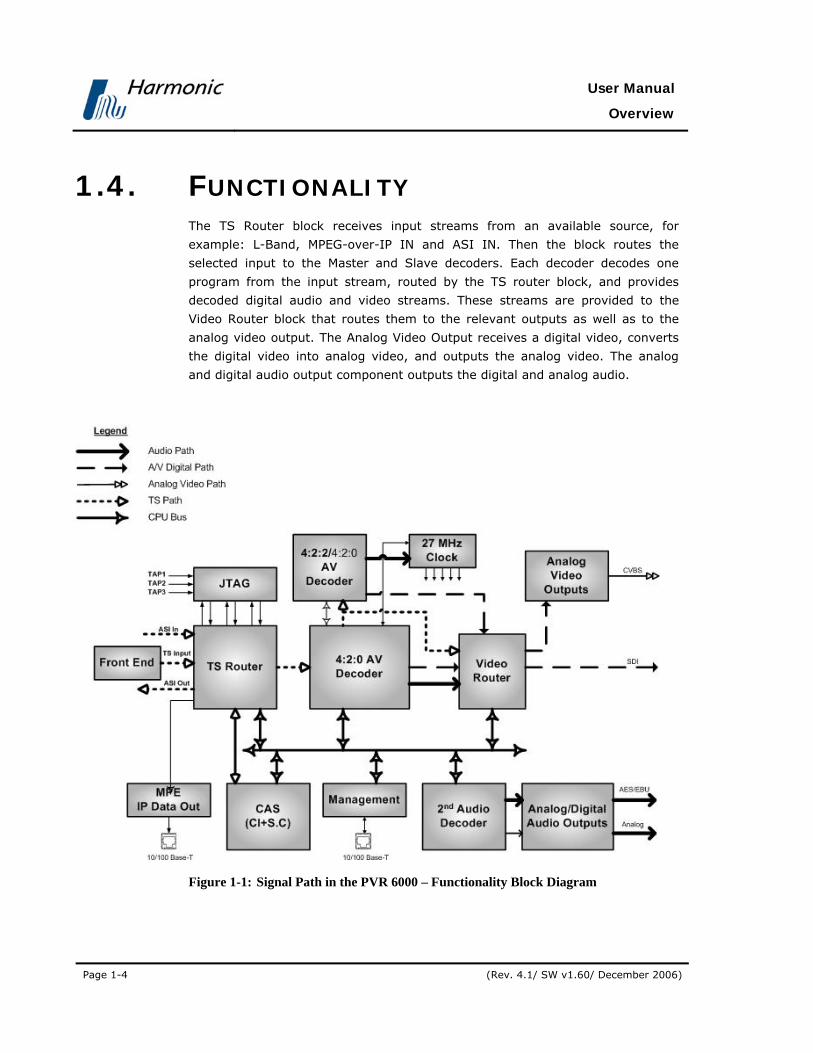
1.4. FUNCTIONALITY The TS Router block receives input streams from an available source, for
example: L-Band, MPEG-over-IP IN and ASI IN. Then the block routes the
selected input to the Master and Slave decoders. Each decoder decodes one
program from the input stream, routed by the TS router block, and provides
decoded digital audio and video streams. These streams are provided to the
Video Router block that routes them to the relevant outputs as well as to the
analog video output. The Analog Video Output receives a digital video, converts
the digital video into analog video, and outputs the analog video. The analog
and digital audio output component outputs the digital and analog audio.
Figure 1-1: Signal Path in the PVR 6000 – Functionality Block Diagram

PVR 6000 Series
Professional Integrated Receiver Decoders
Page 1-5
1.5. MECHANICAL STRUCTURE The PVR 6000 is housed in a rugged industrial enclosure, 1RU by 19" (rack
mount).
Figure 1-2: PVR 6000 Unit
1.5.1. Front Panel The front panel allows control using a four-way touch pad, [Enter] key, [Esc]
key, and two programmable [F1]/[F2] keys. Operational commands and
parameters are displayed on a graphical LCD. The four-way touch pad allows
parameter modification and scrolling through the embedded VBI menus. Two
LEDs show the WARNING and PWR/FAIL status (see Figure 1-3).
Figure 1-3: Front View of the IRD

User Manual
Overview
Page 1-6 (Rev. 4.1/ SW v1.60/ December 2006)
1.5.2. Various Front-Ends PVR 6000 supports the following interfaces:
• DVB-S Single L-Band input
• DVB-S Dual L-Band input
• DVB-DSNG Dual L-Band input
• DVB-S2 Dual L-Band input
• MPEG over IP (MPEGoIP) dual input
• G.703 E3 single input with Loop-through
• ASI-In Decoder only (except for PVR 6000)
In this manual all rear panels are displayed with the DVB-S interface. Each
model has standard features and interfaces as well as features requiring active
software licenses.
The MPEGoIP input interface can be supported by all PVR 6000 devices. Figure
1-4 illustrates the PVR 6010 rear panel with an MPEGoIP input interface.
Figure 1-4: PVR 6010 Rear Panel (IP Input interface)
Figure 1-5 illustrates the PVR 6010 rear panel with DVB-S (QPSK) Dual Input
configuration.
Figure 1-5: PVR 6010 Rear Panel (DVB-S Dual Input interface)

PVR 6000 Series
Professional Integrated Receiver Decoders
Page 1-7
Figure 1-6 displays the PVR 6010 rear panel with Decoder Only configuration.
Figure 1-6: PVR 6010 Rear Panel (Decoder Only interface)
NOTE
PVR 6000 models supporting MPEGoIP output and IP data out (MPE
de-capsulation) output can be configured to support either MPEGoIP or IP data
out.
1.5.3. Software Permission (Licensing) Each PVR 6000 model is provided with a basic feature package. In order to suit
specific requirements, additional license-permitted features are available. The
Next chapter specifies the basic and optional features available for each model.
In order to enable optional features perform one of the following:
• Upon unit ordering - order the relevant features. The unit will be
provided with the ordered features enabled.
• After unit ordering - order the relevant features. In this case, a 16
character key issued by Harmonic Inc. will be provided. The key must
be entered to the unit thru the front-panel or the web-interface. For
details see section 4.2.10.5
NOTE
When RS-232 low-speed-data and/or RS-422 high-speed-data are enabled
the PID Filtering is unavailable.

User Manual
Overview
Page 1-8 (Rev. 4.1/ SW v1.60/ December 2006)
1.5.4. PVR 6000 models
1.5.4.1. PVR 6000 Interfaces and Features
The PVR 6000 is a single 4:2:0 Decoder IRD. The PVR 6000 devices consist of
two composite video interfaces. The CVBS #1 connector is used for broadcasting
quality video and the CVBS #2 connector is used for monitoring.
Figure 1-7 illustrates the PVR 6000 rear panel. The PVR 6000 basic features and
software-licensed features are also detailed.
Figure 1-7: PVR 6000 Rear Panel (Standard)
Basic Features
• 1 composite video - Broadcast
quality (upper connector)
• 1 composite video - Monitoring
quality (lower connector)
• 2 active analog – audio - stereo
balanced interfaces
• GPI
Software-Licensed Features
• Dolby digital (AC-3) LT/RT
downmixing
• RS-232 low speed data output
• RS-422 high speed data output
NOTES
The PVR 6000 does not support the Decoder Only configuration.
The Russian SECAM D/K (composite video only) is available only through Special
orders.

PVR 6000 Series
Professional Integrated Receiver Decoders
Page 1-9
1.5.4.2. PVR 6010 Interfaces and Features
The PVR 6010 is a single 4:2:0 decoder IRD. The PVR 6010 family consists of
two composite video interfaces. The CVBS #1 connector is used for broadcast
quality video and the CVBS #2 connector is used for monitoring.
Figure 1-8 illustrates the PVR 6010rear panel. The PVR 6010basic features and
software-licensed features are also detailed.
Figure 1-8: PVR 6010Rear Panel
Basic Features
• 1 composite video - Broadcast
quality (upper connector)
• 1 composite video - Monitoring
quality (lower connector)
• 2 active analog – audio - stereo
balanced interfaces
• SNMP management (10/100 Base-T)
• Web based management
(10/100Base-T)
• GPI
Software-Licensed Features
• ASI Input
• Dual (identical) ASI outputs
• MPEG-over-IP output or IP data
output (MPE de-capsulation)
• Dolby Digital (AC-3) LT/RT
downmixing
• Genlock input and loop-through
output
• Pro MPEG FEC
• IP Dual input (link and source
redundancy
• PID and service filtering
• RS-232 low speed data output
NOTES
In the case of power failure or system shutdown, ASI OUT 1 output will become
ASI loop-through. Use ASI OUT 1 output for cascading a chain of PVR 6000.
The Russian SECAM D/K (composite video only) is available only through special
orders.

User Manual
Overview
Page 1-10 (Rev. 4.1/ SW v1.60/ December 2006)
1.5.4.3. PVR 6020 Interfaces and Features
The PVR 6020 is a single 4:2:0 decoder. The entire PVR 6020 family consists of
two composite video interfaces. The CVBS #1 connector is used for broadcast
quality video and the CVBS #2 connector can is for monitoring.
Figure 1-9 illustrates the PVR 6020 rear panel. The PVR 6020 basic features and
software-licensed features are also detailed.
Figure 1-9: PVR 6020 Rear Panel
Basic Features
• 1 composite video - Broadcast
quality (upper connector)
• 1 composite video - Monitoring
quality (lower connector)
• 2 SDI interfaces
• Embedded VBI and up to 2 stereo
channels in SDI
• 2 activated analog-audio-stereo
balanced interfaces
• 2 activated AES/EBU-SPDIF audio-
unbalanced interfaces
• SNMP management (10/100 Base-T)
• Web-based management (10/100
Base-T)
• GPI
• Front panel A/V monitoring
connectors
Software-Licensed Features
• ASI Input
• Dual (identical) ASI outputs
• MPEG-over-IP output or IP data
output (MPE de-capsulation)
• Genlock input and loop-through
output
• Dolby Digital (AC-3) LT/RT
downmixing.
• Pro MPEG FEC
• PID and service filtering
• H.264 (One Program Only)
• RS-232 low speed data output

PVR 6000 Series
Professional Integrated Receiver Decoders
Page 1-11
NOTE
In the case of power failure or system shutdown, ASI OUT 1 output will become ASI loop-through. Use ASI OUT 1 output for cascading a chain of PVR 6000.
1.5.4.4. PVR 6030 Interfaces and Features
The PVR 6030 is a single 4:2:0 decoder. The entire PVR 6030 family consists of
two composite video interfaces. The CVBS #1 connector is used for broadcast
quality video and the CVBS #2 connector is used for monitoring.
Figure 1-10 illustrates the PVR 6030 rear panel. The PVR 6030 basic features
and software-licensed features are described below.
Figure 1-10: PVR 6030 Rear Panel
Basic Features
• 1 composite video - Broadcast
quality (upper connector)
• 1 composite video - Monitoring
quality (lower connector)
• 2 SDI interfaces
• Embedded VBI and up to 2 stereo
channels in SDI
• 2 active analog-audio-stereo
balanced interfaces
• 2 active AES/EBU-SPDIF audio-
balanced interfaces
• SNMP management (10/100 Base-T)
• Web-based management (10/100
Base-T)
• GPI
• Front panel A/V monitoring
connectors
Software-Licensed Features
• ASI input
• Dual (identical) ASI output
• MPEG-over-IP output or IP data
output (MPE de-capsulation)
• Genlock input and loop-through
output
• Dolby Digital (AC-3) LT/RT
downmixing
• Pro MPEG FEC
• IP Dual input (link and source
redundancy
• PID and service filtering
• RS-232 low speed data output

User Manual
Overview
Page 1-12 (Rev. 4.1/ SW v1.60/ December 2006)
NOTES
This model requires a breakout cable to connect to the AES/EBU interfaces.
In case of power failure or system shutdown, ASI OUT 1 output will become ASI
loop-through. Use ASI OUT 1 output for cascading a chain of PVR 6000
1.5.4.5. PVR 6040 Interfaces and Features The PVR 6040 is a single 4:2:0/4:2:2 decoder. The PVR-6040 family consists
of two composite video interfaces. Both CVBS #1 and CVBS #2 connectors are
for broadcast quality video.
Figure 1-11 illustrates the PVR 6040 rear panel. The PVR 6040 basic and
software-licensed features are also detailed.
Figure 1-11: PVR 6040 Rear Panel
Basic Features
• 2 composite video interfaces –
Broadcast quality
• 2 SDI interfaces
• Embedded VBI and up to 4 stereo
channels in SDI
• Decoding 4:2:2 PP@ML (1.5–50 Mbps)
• 2 out of 4 active analog-audio-stereo
balanced interfaces
• 2 out of 4 active AES/EBU-SPDIF audio
unbalanced interfaces
• 1ST and 2ND active AES/EBU-SPDIF
• SNMP management (10/100 Base-T)
• Web-based management (10/100
Base-T)
• GPI
• Front panel A/V monitoring connectors
Software-Licensed Features
• ASI input
• Dual (identical) ASI output
• MPEG-over-IP output or IP data output (MPE
de-capsulation)
• 3RD Active analog stereo pair
• 4TH Active analog stereo pair
• 3RD Active AES/EBU-SPDIF
• 4TH Active AES/EBU-SPDIF
• Dolby Digital (AC-3) LT/RT downmixing
• Linear PCM (SMPTE 302M 2000), Dolby-E
pass-through
• Pro MPEG FEC
• IP Dual input (link and source redundancy
• PID and service filtering
• RS-232 low speed data output
PVR 6000 Series
Professional Integrated Receiver Decoders
Page 1-13
NOTES
This model requires a breakout cable to connect to the 3rd and 4th analog stereo
pairs.
In the case of power failure or system shutdown, ASI OUT 1 output will become
ASI loop-through. Use ASI OUT 1 output for cascading a chain of PVR 6000.
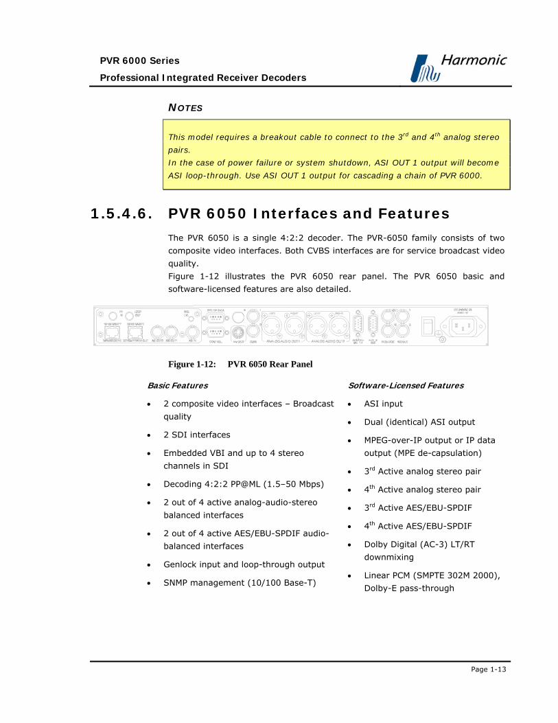
1.5.4.6. PVR 6050 Interfaces and Features
The PVR 6050 is a single 4:2:2 decoder. The PVR-6050 family consists of two
composite video interfaces. Both CVBS interfaces are for service broadcast video
quality.
Figure 1-12 illustrates the PVR 6050 rear panel. The PVR 6050 basic and
software-licensed features are also detailed.
Figure 1-12: PVR 6050 Rear Panel
Basic Features
• 2 composite video interfaces – Broadcast
quality
• 2 SDI interfaces
• Embedded VBI and up to 4 stereo
channels in SDI
• Decoding 4:2:2 PP@ML (1.5–50 Mbps)
• 2 out of 4 active analog-audio-stereo
balanced interfaces
• 2 out of 4 active AES/EBU-SPDIF audio-
balanced interfaces
• Genlock input and loop-through output
• SNMP management (10/100 Base-T)
Software-Licensed Features
• ASI input
• Dual (identical) ASI output
• MPEG-over-IP output or IP data
output (MPE de-capsulation)
• 3rd Active analog stereo pair
• 4th Active analog stereo pair
• 3rd Active AES/EBU-SPDIF
• 4th Active AES/EBU-SPDIF
• Dolby Digital (AC-3) LT/RT
downmixing
• Linear PCM (SMPTE 302M 2000),
Dolby-E pass-through
User Manual
Overview
Page 1-14 (Rev. 4.1/ SW v1.60/ December 2006)
• Web-based management (10/100
Base-T)
• GPI
• Front panel A/V monitoring connectors
• Genlock input and loop-through
output
• Dolby Digital (AC-3) LT/RT
downmixing.
• Pro MPEG FEC
• PID and service filtering
• H.264 (One Program Only)
• RS-232 low speed data output
NOTES
This model requires a breakout cable to connect to the AES/EBU interfaces and
to connect to the 3rd and 4th analog stereo pairs.
In the case of power failure or system shutdown, ASI OUT 1 output will become
ASI loop-through. Use ASI OUT 1 output for cascading a chain of PVR 6000.

PVR 6000 Series
Professional Integrated Receiver Decoders
Page 1-15
1.5.4.7. PVR 6060 Interfaces and Features
The PVR 6060 is a dual 4:2:0 decoder. The PVR-6060 family consists of three
composite video interfaces. The CVBS #1 connector is for the broadcast quality
video of decoder #1. The CVBS #2 is used for monitoring. The CVBS #3
connector is for the broadcast quality video of decoder #2.
Figure 1-13 illustrates the PVR 6060 rear panel. The PVR 6060 basic and
software-licensed features are also detailed.
Figure 1-13: PVR 6060 Rear Panel
Basic Features
• 1 composite video for program 1- Broadcast
quality (upper-right connector)
• 1 composite video for program 2 -
Broadcast quality (upper-left connector)
• 1 composite video for program 1-
Monitoring quality (lower connector)
• 4 active analog-audio-stereo balanced
interfaces
• SNMP management (10/100 Base-T)
• Web-based management (10/100 Base-T)
• RS-422 high speed data output
• GPI
Software Licensed Features
• ASI input
• Dual (identical) ASI output
• Dolby Digital (AC-3) LT/RT
downmixing
• H.264 (One program only)
• RS-232 low speed data output
• RS-422 high speed data output
NOTE
In the case of power failure or system shutdown, ASI OUT 1 output will become
ASI loop-through. Use ASI OUT 1 output for cascading a chain of PVR 6000.
The Russian SECAM D/K (composite video only) is available only through special
orders.

User Manual
Overview
Page 1-16 (Rev. 4.1/ SW v1.60/ December 2006)
1.5.4.8. PVR 6070 Interfaces and Features The PVR 6070 is a dual 4:2:0 decoder. The PVR-6070 family consists of three
composite video interfaces. The CVBS #1 connector is for the broadcast quality
video of decoder #1. The CVBS #2 is used for monitoring. The CVBS #3
connector is for broadcast quality video of decoder #2.
Figure 1-13 illustrates the PVR 6070 rear panel. The PVR 6070 basic features
and software-licensed features are also detailed.
Figure 1-14: PVR 6070 Rear Panel
Basic Features
• 3 composite video interfaces (2 for
broadcast, 1 for monitoring)
• 2 SDI interfaces
• Embedded VBI and up to 4 stereo
channels in SDI
• 4 active analog-audio-stereo
balanced interfaces
• 4 active AES/EBU-SPDIF audio
unbalanced interface
• SNMP management (10/100
Base-T)
• Web-based management (10/100
Base-T)
• GPI
Software-Licensed Features
• ASI input
• Dual (identical) ASI output
• MPEG-over-IP output or IP data
output (MPE de-capsulation)
• Dolby Digital (AC-3) LT/RT
downmixing
• Linear PCM (SMPTE 302M 2000),
Dolby-E pass-through.
• Pro MPEG FEC
• H.264 (One program only)
• PID and service filtering
• RS-232 low speed data output

PVR 6000 Series
Professional Integrated Receiver Decoders
Page 1-17
NOTES
This model requires a breakout cable to connect to the 3rd and 4th analog
stereo pairs.
In case of power failure or system shutdown, ASI OUT 1 output will become ASI
loop-through. Use ASI OUT 1 output for cascading a chain of PVR 6000.
1.5.4.9. PVR 6080 Interfaces and Features
The PVR 6080 is a dual 4:2:0 decoder. The PVR-6080 family consists of three
composite video interfaces. The CVBS #1 is for service broadcast video quality.
The CVBS #2 is for service monitoring and OSD video quality. The CVBS #3 is
for additional service broadcast video quality.
Figure 1-15 illustrates the PVR 6080 rear panel. The PVR 6080 basic features
and software-licensed features are also detailed.
Figure 1-15: PVR 6080 Rear Panel
Basic Features
• 3 composite video interfaces (2 for
broadcast, 1 for monitoring)
• 2 SDI interfaces
• Embedded VBI and up to 4 stereo
channels in SDI
• 4 active analog-audio-stereo
balanced interfaces
• 4 active AES/EBU-SPDIF audio
balanced interfaces
• SNMP management (10/100 Bas-
T)
• Web-based management (10/100
Base-T)
Software-Licensed Features
• ASI input
• Dual (identical) ASI output
• MPEG-over-IP output or IP data
output (MPE de-capsulation)
• Genlock input and loop-through
output
• Dolby Digital (AC-3) LT/RT
downmixing
• Linear PCM (SMPTE 302M 2000),
Dolby-E pass-through
• Pro MPEG FEC
• H.264 (One program only)
• PID and service filtering

User Manual
Overview
Page 1-18 (Rev. 4.1/ SW v1.60/ December 2006)
• GPI • RS-232 low speed data output
NOTES
This model requires a breakout cable to connect to the AES/EBU interfaces and
to connect to the 3rd and 4th analog stereo pairs.
In the case of power failure or system shutdown, ASI OUT 1 output will become
ASI loop-through. Use ASI OUT 1 output for cascading a chain of PVR 6000
1.6. MANAGEMENT The following sections detail the different management interfaces and methods
available to control the PVR 6000.
1.6.1. Local Management The PVR 6000 supports two local management methods:
• Front Panel Control - The PVR 6000 front panel provides an easy to use
graphical display with a large LCD screen and intuitive control.
• PC Terminal Control - The PVR 6000 supports PC terminal control from a
standard PC terminal (over RS-232 or RS-485). The terminal provides
access to control and monitor functionalities that are not available when
using any PVR 6000 front panel feature.
1.6.2. Remote Management PVR 6000 supports three remote management methods:
• NMS-4000 and Future NMS-7000 - The NMS-4000 Network Management
System enables management of the PVR 6000 through the transmission link.
The NMS-4000 provides a menu and dialog-driven interface from which
control, modification, and upgrade operations can be performed on the IRD.
• Web-Based Management - PVR 6000 supports web-based management.
Managing PVR 6000 parameters using web-based control is as easy as point-
and-click.
• Telnet - The PVR 6000 supports remote control throughout the Internet.
The PVR 6000 can be controlled and configured from a standard PC terminal
(over Ethernet). The terminal provides access to control and monitor
PVR 6000 Series
Professional Integrated Receiver Decoders
Page 1-19
functionalities that are not available when using any PVR 6000 front panel
feature.
1.7. CHARACTERISTICS AND
SPECIFICATIONS The following section provides with the PVR 6000 Characteristics and
specification.
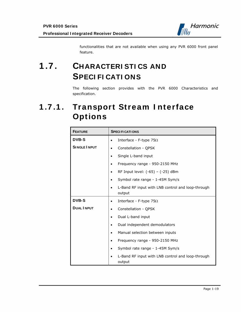
1.7.1. Transport Stream Interface Options
FEATURE SPECIFICATIONS
DVB-S
SINGLE INPUT
• Interface - F-type 75Ω
• Constellation - QPSK
• Single L-band input
• Frequency range - 950-2150 MHz
• RF Input level: (-65) – (-25) dBm
• Symbol rate range - 1-45M Sym/s
• L-Band RF input with LNB control and loop-through
output
DVB-S
DUAL INPUT
• Interface - F-type 75Ω
• Constellation - QPSK
• Dual L-band input
• Dual independent demodulators
• Manual selection between inputs
• Frequency range - 950-2150 MHz
• Symbol rate range - 1-45M Sym/s
• L-Band RF input with LNB control and loop-through
output
User Manual
Overview
Page 1-20 (Rev. 4.1/ SW v1.60/ December 2006)
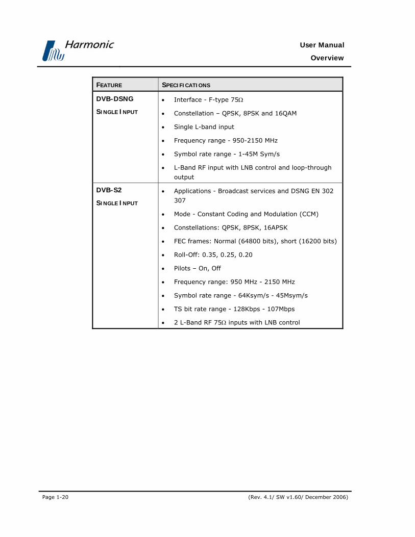
FEATURE SPECIFICATIONS
DVB-DSNG
SINGLE INPUT
• Interface - F-type 75Ω
• Constellation – QPSK, 8PSK and 16QAM
• Single L-band input
• Frequency range - 950-2150 MHz
• Symbol rate range - 1-45M Sym/s
• L-Band RF input with LNB control and loop-through
output
DVB-S2
SINGLE INPUT
• Applications - Broadcast services and DSNG EN 302
307
• Mode - Constant Coding and Modulation (CCM)
• Constellations: QPSK, 8PSK, 16APSK
• FEC frames: Normal (64800 bits), short (16200 bits)
• Roll-Off: 0.35, 0.25, 0.20
• Pilots – On, Off
• Frequency range: 950 MHz - 2150 MHz
• Symbol rate range - 64Ksym/s - 45Msym/s
• TS bit rate range - 128Kbps - 107Mbps
• 2 L-Band RF 75Ω inputs with LNB control

PVR 6000 Series
Professional Integrated Receiver Decoders
Page 1-21
FEATURE SPECIFICATIONS
MPEGOIP INPUT • Two physical links - 10/100 Base-T, RJ-45 – one
active at a time
• Two logical sources (sockets) – one active at a time
• Physical Link and logical source redundancy
(coupled)
• De-Jittering buffer size - configurable 0-2000mSec
• TS bit rate: up to 44 Mbps
• Encapsulation type: UDP and RTP (Automatic
detection)
• SPTS/MPTS
• Unicast/Multicast
• IGMPv2
• Forward Error Correction (FEC)
• ProMPEG CoP3v2
• Maximum input bit-rate: 25Mb/s
• Columns only FEC protection
• Matrix dimensions - Columns 1-20, Rows 4-20.
Columns*Rows ≤ 100 (Automatic detection)
MPEGOIP OUTPUT • TS bit rate - up to 60 Mbps
• SPTS/MPTS
• Encapsulation - UDP
• All programs and PIDs are present in the output TS
• Interface 10/100 Base-T, RJ-45
DVB-ASI INPUT • Interface: copper, BNC 75 ohm
• TS bit rate: up to 100 Mbps (Byte and Burst mode)

User Manual
Overview
Page 1-22 (Rev. 4.1/ SW v1.60/ December 2006)
FEATURE SPECIFICATIONS
DVB-ASI OUTPUT • 2 ASI connectors: copper, BNC 75 ohm
• ASI options:
• ASI OUT 1 - output stream with decrypted
selected program, output stream and loop-
through
• ASI OUT 2 - output stream with decrypted
selected program, output stream
• ASI output rate - up to 100 Mbps (Byte mode)
TELECOM G.703
INPUT • Unframed PDH Data rates::E1,E2 or E3
• FEC (optional): DVB-C FEC
• Loop-through output
DVB-PDH INPUT • Interface: ATM AAL-1
• Data rates: DS3 or E3
• Loop-through output
1.7.2. Advanced Processing FEATURE SPECIFICATIONS
SERVICE AND PID
FILTERING • Active on ASI and IP outputs
• PCR re-stamping
• VBR and CBR modes (NULL stuffing)
• Forward only and filter only modes
• Dynamic Service filtering (tracks PIDs'
modifications)
• Static PID filtering
• PSI/SI tables are not modified.

PVR 6000 Series
Professional Integrated Receiver Decoders
Page 1-23
FEATURE SPECIFICATIONS
DATA • High speed data: RS-422 Up to 20 Mbps, RJ-45
(supported by PVR 6000 , PVR 6060 )
• IP Data Out (RJ-45): up to 60Mbps (MPE de-
capsulation)
1.7.3. Decoder Outputs
FEATURE SPECIFICATIONS
VIDEO • Video Formats:
• PAL-B/G/I/M/N/D, NTSC, SECAM L/B/G/K1
• Russian SECAM D/K (composite video only
supported only by special order in PVR 6000 ,
PVR 6010and PVR 6060 )
• Decoding:
• 4:2:0 MP@ML (1.5 – 15 Mbps)
• 4:2:2 PP@ML (1.5 – 50 Mbps) (supported only
in IRD298x)
• Maximum TS decoding bit rate: 108Mbps
• Video resolution interpolation: Pan-scan, letter box
or Pass through
• Aspect ratios: 4:3/16:9
• Aspect ratio 14:9 by signaling over VBI video index
• Graphical processing (OSD): DVB subtitling, EBU
(Teletext) subtitling
• OSD only through monitoring output
• Genlock input and loop-through output (supported
only by IRD2962, IRD2963, IRD2981 and
IRD2992)
• Genlock Sync lock resolution: +/- 37nSec

User Manual
Overview
Page 1-24 (Rev. 4.1/ SW v1.60/ December 2006)
FEATURE SPECIFICATIONS
FRONT PANEL
MONITORING • Video monitor output connector (Supported only by
298x)
• Audio monitor output connector (Supported only by
298x)
VBI RE-INSERTION • All VBIs adhere the relevant standards including
the line numbers
• In composite video and embedded SDI
• WST Teletext and inverted Teletext
• WSS, VPS, VITC, CC, AMOL I, AMOL II (Nielsen),
TV-Guide, V-CHIP
• Enhanced VITS with built-in generator
AUDIO • Modes: stereo, joint stereo, dual channel, single
channel
• Analog max output level: +18 dBu @ 600Ω
• Digital max output level: 0 dBFs
• Attenuation control at -64 dB to 0 dB and mute
• Dolby Digital (AC-3) Pass-through
• Dolby Digital (AC-3) LT/RT downmixing
• Linear PCM (SMPTE 302M 2000) supported over
analog and digital outputs 2/3/4 (supported in
IRD2980, IRD2981, IRD2991, IRD2992)
• Dolby-E pass-through supported over digital
outputs 2/3/4 (supported in IRD2980, IRD2981,
IRD2991, IRD2992)

PVR 6000 Series
Professional Integrated Receiver Decoders
Page 1-25
1.7.4. Conditional Access
FEATURE SPECIFICATIONS
EMBEDDED DVB-DESCRAMBLING
• BISS mode-1
• BISS-E
• CAS-5000
DVB-CI • Interface – 2 CI slots EN-50221 (Only 1 active
simultaneously)
• Maximum of decrypted programs - 1 for single
decoder, and 2 for dual decoder (in case the
specific CAM supports it).
• Maximum TS bitrate – 72 Mbps
• CA methods: Multicrypt, Simulcrypt
• CASs: Viaccess®, Irdeto®, Conax®,
MediaGuard®, Nagravision®, Cryptoworks®,
VideoGuard®, OnDigital®, CODICrypt®
1.7.5. Control and Monitoring
FEATURE SPECIFICATIONS
LOCAL • Graphical easy-to-use front panel
• Advanced satellite scanning (CLI support only)
• Operates in service and PID modes
• 2 GPI dry contacts for various status and fault
indications
ENHANCED DVB
MONITORING • Front panel display: signal quality, Eb/N0, BER,
ASI format, network and service information, CA
information, CI slots, video and audio decoded
information

User Manual
Overview
Page 1-26 (Rev. 4.1/ SW v1.60/ December 2006)
REMOTE • SNMP management
• Web-based management
• Telnet
• Terminal via RS-232 or RS-485
• Software download
OVER THE AIR • Software download
1.7.6. Compliance
FEATURE SPECIFICATIONS
EMC • EN55013 (CISPR 13)
• EN55020 (CISPR 20)
• EN55022 (CISPR 22)
• EN55024 (CISPR 24)
• FCC part 15 (Class B)
SAFETY • EN60950
• CB (IEC60950)
• UL60950
• cTUVus
1.7.7. Environmental Conditions
FEATURE SPECIFICATIONS
OPERATION • Temperature - 0°C - 50°C
• Humidity - 5% - 90% (non-condensing)
STORAGE AND
TRANSPORTATION • Temperature - -40°C - 70°C
• Humidity - 0% - 95% (non-condensing)

PVR 6000 Series
Professional Integrated Receiver Decoders
Page 1-27
1.7.8. Physical and Power Specifications
FEATURE SPECIFICATIONS
PHYSICAL • 1RU unit, 19’’ rack mountable
• Dimensions (HxWxD) –
1RU X 19” X 14”/44mm X 482.6mm X 357mm
• Weight – 3.5Kg. (7.7lbs).
POWER • Voltage:
• 100 - 240V AC, 50/60Hz
• Power consumption – up to 50w max

PVR 6000 Series
Professional Integrated Receiver Decoders
Page 2-1
Chapter 2. INSTALLATION
This section details the safety precautions and inventory check when installing
the ProView™ PVR 6000.
2.1. SAFETY PRECAUTIONS To avoid injury and prevent equipment damage, observe the following safety
precautions:
• Do not move or ship equipment unless it is correctly packaged in its original
wrapping and shipping containers.
• Only Harmonic Inc. trained personnel can perform service and maintenance.
• To prevent lightning damage, ground the unit according to local regulations.
• Do not permit unqualified personnel to operate the unit.
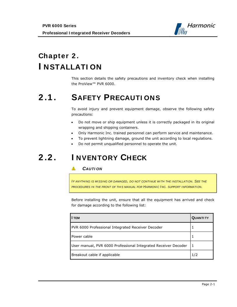
2.2. INVENTORY CHECK CAUTION
IF ANYTHING IS MISSING OR DAMAGED, DO NOT CONTINUE WITH THE INSTALLATION. SEE THE
PROCEDURES IN THE FRONT OF THIS MANUAL FOR HARMONIC INC. SUPPORT INFORMATION.
Before installing the unit, ensure that all the equipment has arrived and check
for damage according to the following list:
ITEM QUANTITY
PVR 6000 Professional Integrated Receiver Decoder 1
Power cable 1
User manual, PVR 6000 Professional Integrated Receiver Decoder 1
Breakout cable if applicable 1/2

User Manual
Installation
Page 2-2 (Rev. 4.1/ SW v1.60/ December 2006)
2.3. INSTALLATION INSTRUCTIONS This section explains the mechanical installation of the rack and PVR 6000
device.
2.3.1. Site Preparation When installing the PVR 6000 in a standard 19" rack, verify that the rack is fully
prepared for the installation. To facilitate easy access during installation and
maintenance, leave sufficient space behind the rack.
The PVR 6000 must be installed within 1.5m (5 feet) from an easily accessible
grounded AC outlet, capable of furnishing the required supply voltage as
detailed in Section 2.5.1.
The use of a UPS (Uninterrupted Power Supply) and an AVR (Automated Voltage
Regulation) is highly recommended to ensure uninterrupted operation.
Ensure that a qualified electrician has installed the main power supply in
accordance with local power authority regulations. All powering should be wired
with an earth leakage in accordance with local regulations.
WARNING
TO AVOID ELECTROCUTION ENSURE THAT THE RACK HAS BEEN
CORRECTLY GROUNDED BEFORE SWITCHING ON THE PVR 6000 DEVICE.
WHEN REMOVING THE UNIT, REMOVE THE GROUNDED CONNECTION
ONLY AFTER THE UNIT IS SWITCHED OFF AND UNPLUGGED.
2.3.2. Mechanical Rack Installation Due to its considerable weight, the device must be placed on a pair of rack-
slides, specially designed for this product (see Figure 2-1).
CAUTION
THE RACK-SLIDES MUST BE INSTALLED IN THE DEVICE’S DESIGNATED LOCATION WITHIN THE RACK,
SINCE THEY ARE INTENDED TO CARRY THE DEVICE’S WEIGHT. DO NOT RELY ONLY ON THE
DEVICE’S MOUNTING BRACKETS FOR SUPPORTING THE DEVICE’S WEIGHT. DOING SO MAY RESULT
IN DAMAGE TO THE RACK, DEVICE, AND OTHER MOUNTED DEVICES.

PVR 6000 Series
Professional Integrated Receiver Decoders
Page 2-3
Figure 2-1: Pair of Rack Slides
Slide structure is especially designed to ensure proper ventilation of these
products, as it is consistent with the ventilation scheme of all Harmonic Inc.
rack-mount devices.
CAUTION
USING RACK-SLIDES THAT ARE NOT SPECIALLY DESIGNED FOR HARMONIC INC. RACK-MOUNT
DEVICES MAY RESULT IN OVERHEATING AND DAMAGE TO ONE OR MORE MOUNTED DEVICES.

User Manual
Installation
Page 2-4 (Rev. 4.1/ SW v1.60/ December 2006)
Figure 2-5 illustrates the exact measurements of special rack-slides.
Figure 2-2: Rack Slide Measurement Specifications
Fasten the pair of rack slides to the rack’s side rails in the device’s designated
location with four M6 screws (two on each side of the rack) before continuing.
After tightly fastening the supporting rack-slides to the rack, perform the
following steps to install the device within the rack:
1. Lay the device on the rack-slides in its designated location within the rack.
Figure 2-3 is a see-through illustration, demonstrating the placing of the
device on the rack-slides.

PVR 6000 Series
Professional Integrated Receiver Decoders
Page 2-5
Figure 2-3: Laying the Device on the Rack-Slides
2. The device is supplied with two mounting brackets (see Figure 2-4). The
mounting brackets are clipped to the device chassis on both sides before
leaving the factory. Align the mounting brackets’ holes with the relevant
holes in the rack’s side rails.
Figure 2-4: Clipped Mounting Brackets
3. Fasten the mounting brackets to the side-rails with four screws (two on each
side). The device is now safely installed within the rack.

User Manual
Installation
Page 2-6 (Rev. 4.1/ SW v1.60/ December 2006)
Figure 2-5 illustrates a general view of the device, when installed within the 19’’
rack.
Figure 2-5: Device Mounted on a Pair of Rack-Slides
A single pair of rack-slides can carry up to 50Kg (110 lbs). This allows saving
rack space by placing a number of rack-mount devices one upon the other (be
careful not to exceed the specified maximum weight).
WARNING
DO NOT APPLY OVER 50KG (110LBS) OF WEIGHT ON A SINGLE PAIR OF
RACK-SLIDES. DOING SO MAY RESULT IN COLLAPSING OF THE RACK-
SLIDES, SERIOUS INJURIES TO PERSONNEL, AND DAMAGE TO
EQUIPMENT.

PVR 6000 Series
Professional Integrated Receiver Decoders
Page 2-7
Figure 2-6 illustrates multiple devices when rack-mounted on a single pair of
rack-slides.
Figure 2-6: Multiple Devices Mounted on a Single Pair of Rack-Slides

User Manual
Installation
Page 2-8 (Rev. 4.1/ SW v1.60/ December 2006)
2.3.3. Insertion of the DVB-CI Module (PCMCIA)
CAUTION
DO NOT REMOVE OR INSERT THE DVB-CI MODULE OR THE SMART CARD WHILE THE PVR 6000
IS POWERING UP OR INITIALIZING.
Figure 2-7: DVB-CI Module
Figure 2-7 illustrates the PVR 6000 with the
DVB-CI module (PCMCIA card) and the Smart
Card used to decrypt the incoming signal. The
PVR 6000 is provided with two PCMCIA slots for
up to two DVB-CI modules. The PCMCIA should
be firmly inserted into one of the two provided
slots to ensure contact. Each DVB-CI module
accommodates one Smart Card, inserted with
the UP mark pointing upwards and forward.
When installed, the card is detected
automatically by the PVR 6000 and enabled if the
three following conditions are valid:
• The installed card must be EN50221
compatible
• Services have been selected at TV1/TV2 (for
further information see section 4.2.5.1)
• Using a valid card licensing

PVR 6000 Series
Professional Integrated Receiver Decoders
Page 2-9
2.4. CABLE CONNECTION The PVR 6000 provides all the connections on its rear panel.
The rear panel is comprised of audio outputs, video outputs, data outputs, and
control interfaces (see Table 2-1 for cable connection specifications).
Figure 2-8illustrates the PVR 6080 rear panel in order show connector types.
Figure 2-8: PVR 6080 Rear Panel
Table 2-1: PVR 6000 Rear Panel – Connectors and Cables
INTERFACE CONNECTOR TYPE CABLE TYPE
L-Band Front-end RF IN 75 Ω F-Type RG-6
L-Band Front-end Loop-Through Connector
75 Ω F-Type RG-6
MPEGoIP Input RJ-45 FTP Cat 5
Management RJ-45 FTP Cat 5
MPEGoIP/DATA Output RJ-45 FTP Cat 5
Analog Audio Out1 left 600 Ω XLR (balanced) Shielded audio cable
Analog Audio Out1 right 600 Ω XLR (balanced) Shielded audio cable
Analog Audio Out2 left 600 Ω XLR (balanced) Shielded audio cable
Analog Audio Out2 right 600 Ω XLR (balanced) Shielded audio cable
Video Out, S-Video Y/C 75 Ω DIN connector Super video cable
Composite Video Out, CVBS1 75 Ω BNC RG-59
RG11 A/U (recommended)
Composite Video Out, CVBS2 75 Ω BNC RG-59
RG11 A/U (recommended)
Composite Video Out, CVBS3 75 Ω BNC RG-59
RG11 A/U (recommended)

User Manual
Installation
Page 2-10 (Rev. 4.1/ SW v1.60/ December 2006)
Table 2-1: PVR 6000 Rear Panel – Connectors and Cables
INTERFACE CONNECTOR TYPE CABLE TYPE
Data Output (RS-232/RS-422) 9 PIN D-Type Serial Cable
Control (RS-232/RS-485) 9 PIN D-Type Serial Cable
Audio Balanced 3 & 4 600 Ω D-sub 15p to
4XLR
Breakout Cable
204346 (Harmonic Inc.
material)
AES/EBU 1-4 Unbalanced 75 Ω 4xBNC or
75 Ω D-sub 15p
BNC Cable
ASI in/out1/out2 75 Ω BNC RG-59
RG11 A/U (recommended)
Genlock In 75 Ω BNC RG-59
RG11 A/U (recommended)
Genlock Out 75 Ω BNC RG-59
RG11 A/U (recommended)
SDI out 1 &2 75 Ω BNC RG-59
The ProView™ PVR 6000 supports terminal-control from a standard PC through a
serial RS-232/RS-485 connector.
Figure 2-9 illustrates the Control Interface and Low Speed Data/GPI 9-pin male
connectors pin numbering.
Figure 2-9: 9-Pin Male Connector Pin Numbering
PVR 6000 Series
Professional Integrated Receiver Decoders
Page 2-11
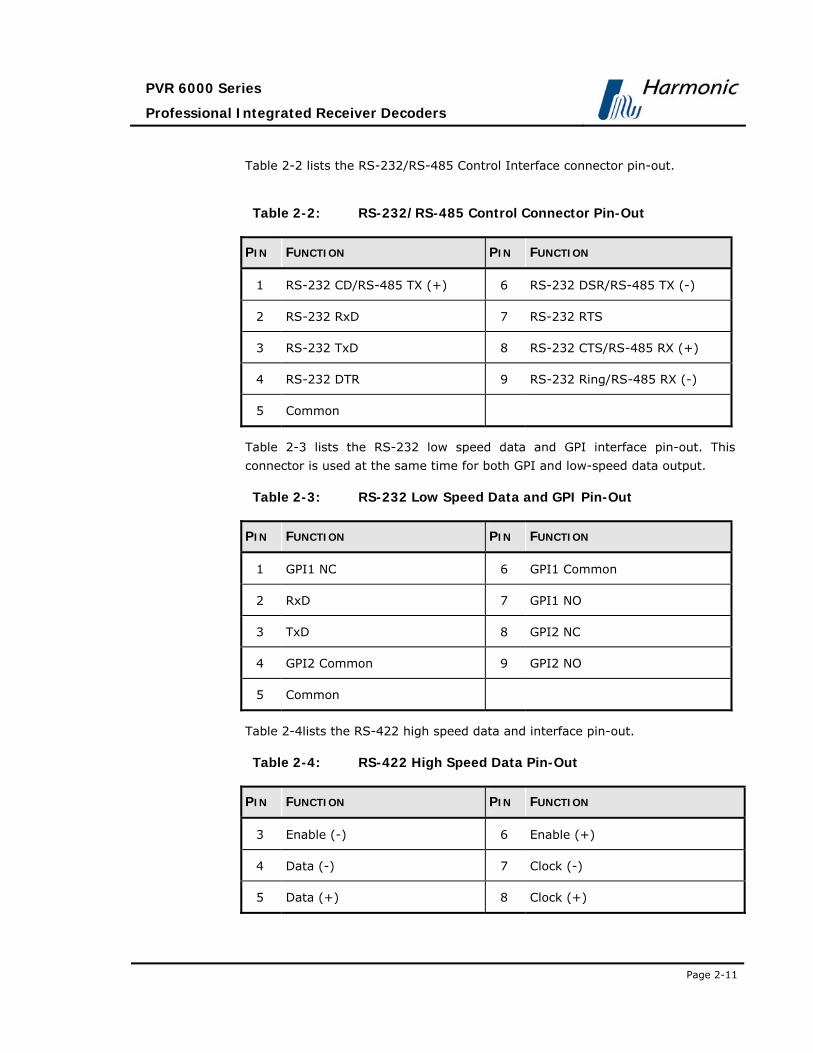
Table 2-2 lists the RS-232/RS-485 Control Interface connector pin-out.
Table 2-2: RS-232/RS-485 Control Connector Pin-Out
PIN FUNCTION PIN FUNCTION
1 RS-232 CD/RS-485 TX (+) 6 RS-232 DSR/RS-485 TX (-)
2 RS-232 RxD 7 RS-232 RTS
3 RS-232 TxD 8 RS-232 CTS/RS-485 RX (+)
4 RS-232 DTR 9 RS-232 Ring/RS-485 RX (-)
5 Common
Table 2-3 lists the RS-232 low speed data and GPI interface pin-out. This
connector is used at the same time for both GPI and low-speed data output.
Table 2-3: RS-232 Low Speed Data and GPI Pin-Out
PIN FUNCTION PIN FUNCTION
1 GPI1 NC 6 GPI1 Common
2 RxD 7 GPI1 NO
3 TxD 8 GPI2 NC
4 GPI2 Common 9 GPI2 NO
5 Common
Table 2-4lists the RS-422 high speed data and interface pin-out.
Table 2-4: RS-422 High Speed Data Pin-Out
PIN FUNCTION PIN FUNCTION
3 Enable (-) 6 Enable (+)
4 Data (-) 7 Clock (-)
5 Data (+) 8 Clock (+)

User Manual
Installation
Page 2-12 (Rev. 4.1/ SW v1.60/ December 2006)
Table 2-5 lists the Audio 3-4 breakout cable interface pin-out.
Table 2-5: Audio 3-4 Breakout Cable Pin-Out (Harmonic Inc. P/N
204346)
PIN FUNCTION PIN FUNCTION
1 Audio 4 XLR Right (+) 8 Audio 4 XLR Left Common
2 Audio 4 XLR Left (+) 10 Audio 3 XLR Left Common
3 Audio 3 XLR Right Common 11 Audio 4 XLR Right (-)
4 Audio 3 XLR Right (+) 12 Audio 4 XLR Left (-)
5 Audio 3 XLR Left (+) 14 Audio 3 XLR Right (-)
7 Audio 4 XLR Right Common 15 Audio 3 XLR Left (-)
Table 2-6 lists the AES/ABU balanced breakout cable pin-out.
Table 2-6: AES/EBU Balanced Breakout Cable Pin-Out (Harmonic Inc.
P/N 204345)
PIN FUNCTION PIN FUNCTION
1 AES/EBU 4 (+) 8 AES/EBU 3 Common
2 AES/EBU 3 (+) 10 AES/EBU 1 Common
3 AES/EBU 2 Common 11 AES/EBU 4 (-)
4 AES/EBU 2 (+) 12 AES/EBU 3 (-)
AES/EBU 1 (+) 14 AES/EBU 2 (-)
7 AES/EBU 4 Common 15 AES/EBU 1 (-)

PVR 6000 Series
Professional Integrated Receiver Decoders
Page 2-13
2.5. INITIALIZATION AND
CONFIGURATION Before powering-up the PVR 6000, ensure that all cabling is correct. Ensure that
the unit is connected to the main power supply and correctly grounded.
2.5.1. Electrical Power Connection The PVR 6000 is powered by an AC power supply unit. Grounding of is provided
when the AC power cable is connected to the device’s AC connector. The PVR
6000 is shipped with either AC connector configuration, as shown in Figure 2-10.
Before powering-up a rack-mounted PVR 6000, the device’s grounding jackscrew
must be connected to the rack housing, which must be correctly grounded (see
Figure 2-10).
AC Power Supply Configuration 1 AC Power Supply Configuration 2
Figure 2-10: Power Supply Configurations and Rack-Mount Grounding Jackscrew

User Manual
Installation
Page 2-14 (Rev. 4.1/ SW v1.60/ December 2006)
2.5.2. Powering Up When powering up the PVR 6000 and the receiver is not tuned, expect one of
the following warnings:
• Front-End warning – Demodulator not sync
• Bit Stream warning – No sync – 0x47 detected
• Bit Stream warning – PSI not detected
In case the PVR 6000 warning LED is lit orange, the operator must perform the
following:
• Tune or configure the PVR 6000 device
• Select a service from the input stream
When the PVR 6000 is correctly configured, “All OK” is displayed and both LEDs
are lit green.
NOTE
Prior to initialization, review Chapter 4-Operation and Management, for how to
use and navigate through the menus and for information on configuration
parameters.
2.5.3. Tuning The PVR 6000 receiver must be configured to receive a transport stream. For
details about an PVR 6000 device with a DVB-S receiver module, see Section
4.2.2. For details about an PVR 6000 device with an MPEG-over-IP front-end
module, see Section 4.2.2.4.

PVR 6000 Series
Professional Integrated Receiver Decoders
Page 2-15
2.5.4. Performing Serviceability Check After installing, initializing, or configuring the IRD, maintenance checks must be
performed to ensure that the unit is serviceable. A video monitor must be
connected to the PVR 6000 to perform the check lists systematic instructions for
performing a serviceability check.
Table 2-7: PVR 6000 Serviceability Check
STEP CHECK
1 On the LCD display, the LCD status message reads "STATUS OK".
2 On the PVR 6000 front panel the two LEDs are lit green.
3 The service selected is displayed on the LCD display.
4 Video picture is displayed on monitor.
5 Audio channels left and right.


PVR 6000 Series
Professional Integrated Receiver Decoders
Page 3-1
Chapter 3. PVR 6000 CONTROL INTERFACES
This section explains the Front Panel and Web Management control interfaces
used for operating, configuring, and monitoring the PVR 6000.
3.1. FRONT PANEL CONTROL
INTERFACE The front panel control interface explained in this section is composed of the
following:
• Controls and Displays – see section 3.1.1
• Front Panel Screens – see section 3.1.2
• Menu Tree – see section 3.1.3
• Front Panel Initialization Sequence – see section 3.1.4
3.1.1. Controls and Displays The front panel is used for extensive local control and for monitoring the device’s
operation. Figure 3-1 illustrates the PVR 6000 front panel.
Figure 3-1: Front Panel
The PVR 6000 front panel contains:
• LCD Display
The LCD display is a large, easy to use, graphical display. It is used to display
enhanced menus with graphical interfaces, such as: charts, radio buttons, tables,
and icons.

User Manual
PVR 6000 Control Interfaces
Page 3-2 (Rev. 4.1/ SW v1.60/ December 2006)
• Status LEDs
The two LEDs indicate WARNING and PWR/FAIL statuses, when both LEDs are lit
green the PVR 6000 status is OK. The WARNING LED (Green/Orange) indicates the
operational status. The PWR/FAIL LED (Green/Red) indicates the hardware status.
• Arrow Keys
The arrow keys include [Up], [Down], [Right], [Left]. The keys are used to
navigate between the different menu items and sub-menus. They are also used
to select and change parameters during setup and configuration procedures.
• [Enter] Key
Used to select or enter a configuration setup.
• [Esc] Key
Used to abort a configuration setup or to return to the menu's previous level.
• Short Cut Keys
Include the [F1]/[F2] buttons that are operator–programmable for
immediate activation of predefined procedures (in the future software
versions).
3.1.2. PVR 6000 Front Panel Screen Types The PVR 6000 display leads to the following five screen types:
• Menu Navigation screen
• Edit Menu screen
• Table Menu screen
• Edit Value screen
• Select Value screen
NOTE
The Front panel can display only up to four menu items at a time. When a menu
has more than four items, the first four are visible in the panel, followed by a
scroll icon [ ]. Additional items can be accessed using the [up]/[down]
arrows. To illustrate the difference between the two types of items, two types of
screen shots were used in this user manual: dark grey for the visible items and
light grey for the hidden ones.

PVR 6000 Series
Professional Integrated Receiver Decoders
Page 3-3
Sections 3.1.2.1 to 3.1.2.5 detail the different front panel screen types.
3.1.2.1. Menu Navigation Screen
The Menu Navigation screen enables navigating through the tree structure of
the PVR 6000 menu.
In this example, the menu navigation screen displays the following items:
Configuration 1-2
1 Receiver
2 Stream
3 Service
4 Video
5 Audio
6 Data
7 Conditional Access
Unit
A. Top line indicates the menu name (Configuration) and the menu hierarchal
position (1-2, for example Configuration under the Root menu).
[ Up]/[ Up/Down]/[ Down] symbols indicate that up or down scrolling
is enabled.
B. Next up to four displayed lines is a list of numbered items.
C. Additional Available Items
The list can include more than four items, but only four items are visible at a
time. When more than four items are enabled, you can scroll using the
[UP]/[Down] arrow keys.
The currently selected option is displayed with white characters over a black
background (see Item #3 in the example above).
To access the next menu level press [Enter] to select the marked item
(either another menu navigation screen or an Edit Menu screen).

User Manual
PVR 6000 Control Interfaces
Page 3-4 (Rev. 4.1/ SW v1.60/ December 2006)
3.1.2.2. Edit Menu Screen
The Edit menu screen enables selecting, changing or displaying the value of a
parameter or set of parameters.
In this example, the Edit Menu screen displays the following items:
Stream 1-2-2
1 Decoder Stream Source FRONT-END (QPSK)
2 27MHz Synchronization STREAM PCR
A. Top line indicates the menu name (Stream) and the menu hierarchal
position (1-2-2, for example Root-Configuration-Stream) in the PVR
6000 Menu Tree. [ Up]/[ Up/Down]/[ Down] symbols indicate that up
or down scrolling is enabled.
B. Next up to four displayed lines is a list of numbered items relevant to the
menu and their current values. The information provided for each list item
is:
• Left-aligned column displays a numbered list of parameters.
• Right-aligned column displays parameter values.
- Editable parameters have a pencil icon next to them.
- Parameters without the pencil icon are for information only.
C. Additional Available Items
The list can include more than four items, but only four items are visible at the
time. When more than four items are enabled, you can scroll the list using the
[UP]/[Down] arrow keys.
The currently selected option is displayed with white characters over a black
background (see Item #1 in the example above).
Press [ESC] to abort the selection or to return to the menu’s previous level.
Press [Enter] to select the pointed editable option; a parameter-editing
screen is displayed. This can be a Table Menu screen, an Edit Value screen, or a
Select Value screen.

PVR 6000 Series
Professional Integrated Receiver Decoders
Page 3-5
3.1.2.3. Table Menu Screen
The Table menu screen displays parameter information, using a table format.
In this example, the Table Menu screen displays the following columns:
Name ID Type Mode
1 PROGRAM 1 000A TV FTA
2 PROGRAM 2 0046 TV FTA
3 PROGRAM 3 0050 TV CAS 4 PROGRAM 4 01F7 TV CAS
A. Top line displays the headers for each table column.
B. Next up to four displayed lines is a numbered list of parameters relevant
to the menu and their current values. A radio button indicates which
parameter is currently active ( is currently enabled and is currently
disabled)
C. Additional Available Items
The list can include more than four items, but only four items are visible at a
time. When more than four items are available, you can scroll the list using
the [UP]/[Down] arrow keys.
The currently selected option is displayed with white characters over a black
background (see Item #2 in the example above).
Press [ESC] to abort the selection and return to the Edit Menu screen
without changing the parameters.
Press [Enter] to select the currently enabled button . The selected option
becomes enabled and the former active option is disabled.

User Manual
PVR 6000 Control Interfaces
Page 3-6 (Rev. 4.1/ SW v1.60/ December 2006)
3.1.2.4. Edit Value Screen
The Edit Value screen enables setting a parameter value. The parameter value
can be a number or a string of characters. Each digit or character is set up
individually.
In this example, the Edit Value screen displays the following information:
Pcr1
1062 [Hex]
<0000 – 1FFF>
A. Top line displays the parameter name (Pcr1). The pencil icon indicates
that the parameter value is editable.
B. Second line displays the current parameter value. Change the value of the
parameter with the arrow keys:
• [Left] and [Right] arrow keys are used to mark a digit or a character
for change. The marked digit or a character is displayed with white
character over black background (see example in page 3-5)
• [Up] and [Down] arrow keys are used to scroll up or down the digits (0
through 9) or the characters (a to z, A to Z, 0 to 9 and so on.). The scroll
range can be limited to prevent values being out of range.
C. Third line displays the allowed range of parameter values.
Press [ESC] to abort the setup and return one level up to the Edit Value
Screen without changing the parameters.
Press [Enter] to accept the value. The display returns one level up to the
Edit Value Screen and the new value is displayed as the current parameter
value.
NOTE
When entering an wrong or out-of-range value the display dismisses the last
change and returns one level up in the menu tree.

PVR 6000 Series
Professional Integrated Receiver Decoders
Page 3-7
3.1.2.5. Select Value Screen (Multiple Choices)
The Select Value screen displays a list of selectable items.
In this example, the Select Value screen displays the following information:
Format
3 PAL M
4 PAL BG
5 PAL D
6 PAL N
A. Top line displays the parameter name (Format). The pencil icon
indicates that the items are selectable from the list of displayed options.
[ Up]/[ Up/Down]/[ Down] symbols indicate that up or down scrolling
is enabled.
B. Next up to four displayed lines is a numbered list of parameters relevant
to the menu and their current values. A radio button indicates which
parameters are currently activated ( is currently enabled and is
currently disabled)
C. Additional Available Items
The list can include more than four items, but only four items are visible at a
time. When more than four items exist, you can scroll the list using the
[UP]/[Down] arrow keys.
The currently selected option is displayed with white characters over a black
background (see Item #4 in the example above).
Press [ESC] to abort setup and return one level up to the Select Value Screen
without changing the parameters.
Press [Enter] to select the marked option (the selected option is enabled and
the former enabled option is disabled ). The display returns up one level to the
Select Value screen; the new option is displayed as the current parameter
option.

User Manual
PVR 6000 Control Interfaces
Page 3-8 (Rev. 4.1/ SW v1.60/ December 2006)
3.1.3. PVR 6000 Menu Tree Setup, control, and monitoring of the PVR 6000 operation can be performed
locally by using the PVR 6000 Menu.
This menu is displayed on the front panel LCD display and is operated using the
front panel control keys. The basic tree structure of the PVR 6000 front panel
menu is illustrated in Figure 3-2.
Figure 3-2: PVR 6000 Front Panel Menu (Root Menu) - Basic Structure

PVR 6000 Series
Professional Integrated Receiver Decoders
Page 3-9
3.1.4. Front Panel Initialization Sequence To activate the PVR 6000 Front Panel Root Menu perform the following:
1. Power up the PVR 6000. The PVR 6000 initialization phase begins and the
initialization message is displayed.
MPEG-2 I.R. Service1:
Initializing
Please Wait...
2. When initialization complete, the PVR 6000 displays one of two options:
• Status OK – Both LEDs are lit green.
Status OK Service1: TV
Click Enter for menu TRT INT
NOTE
Blank Service1 and/or Service2 fields at the front panel' root screen, means
service not chosen. In order to select services see section 4.2.5.1
• Front-End Warning – The warning LED turns orange (For details see
Appendix D). ___________________________________________
Service1:
Click Enter for menu ___________________________________________
3. Click [Enter] to activate and enter the PVR 6000 Root Menu:

User Manual
PVR 6000 Control Interfaces
Page 3-10 (Rev. 4.1/ SW v1.60/ December 2006)
Root 1
1 Preset
2 Configuration
3 Status
The Root Menu provides the following main branch options:
• PVR 6000 Preset Menu – See Section 4.1 for details.
• PVR 6000 Configuration Menu – See Section 4.2 for a detailed
description.
• PVR 6000 Status Menu – See Section 4.3 for details.
3.2. WEB MANAGEMENT INTERFACE The PVR 6000’s Web Management software is a user-friendly graphical interface
that allows easy control and configuration of the device as well as monitoring
the devices current condition. All this is performed through a remote computer,
using a regular Web browser. No additional software is needed. Managing the
PVR 6000 using the Web-based management GUI is as easy as point-and-click.
In order to access the web-management user-name and password must be
entered. The default values are:
• User name – ird
• Password – ird
Enter your user name and password in the access box. Press Submit to confirm
or Clear to start over. For password change see section 4.2.10.2
Figure 3-3 displays the Web Management access box.
Figure 3-3: PVR 6000 Web Management access box
Figure 3-4 displays an example of the Web Management interface window,
demonstrating the commonly used control & management elements.
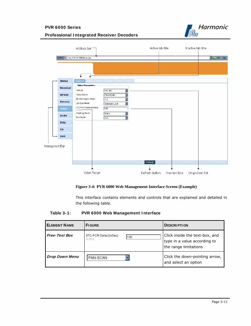
PVR 6000 Series
Professional Integrated Receiver Decoders
Page 3-11
Figure 3-4: PVR 6000 Web Management Interface Screen (Example)
This interface contains elements and controls that are explained and detailed in
the following table.
Table 3-1: PVR 6000 Web Management Interface
ELEMENT NAME FIGURE DESCRIPTION
Free-Text Box Click inside the text-box, and
type in a value according to
the range limitations
Drop Down Menu
Click the down-pointing arrow,
and select an option

User Manual
PVR 6000 Control Interfaces
Page 3-12 (Rev. 4.1/ SW v1.60/ December 2006)
Table 3-1: PVR 6000 Web Management Interface
ELEMENT NAME FIGURE DESCRIPTION
Refresh Button
The Refresh button is located
at the bottom of the Web
management interface
window. Clicking this button
displays the actual, current
PVR 6000 parameter values
that are relevant to the
displayed screen
Web-Browser’s Address Bar
Displays an example of a Web
browser’s address bar. The
address bar is used for
accessing the PVR 6000’s Web
management interface
Management Bar
An easy-to-use, efficient
navigation tool for accessing
the PVR 6000 Web
management screens. It is
generally divided into nine
sections: Status (used for
device monitoring), Receiver
Stream, Service, Video,
Audio, Data, CA, and Unit
(for configuring the device'
properties). Each section has
one or more sub-sections call
Tabs.

PVR 6000 Series
Professional Integrated Receiver Decoders
Page 4-1
Chapter 4. OPERATION AND MANAGEMENT
This chapter provides on controlling the PVR 6000 through its front panel, and
Web management interfaces.
The Front Panel control interface contains all the existing PVR 6000 control
parameters, while the Web management interface allows easy access to the
same parameters from a remote computer. Therefore the description of these
two interfaces is interlaced, and brought together in this chapter.
4.1. PRESET MENU The PVR 6000 Preset main menu will be supported in future software releases.
4.2. CONFIGURATION The Configuration Menu screen allows the user to manage the PVR 6000
through the front panel. The Configuration menu consists of eight sub-menus.
Each sub-menu manages a specific IRD module.
The following lists PVR 6000 configuration sub-menus:
• Receiver - For details, see Section 4.2.1
• Stream - For details, see Section 4.2.3
• Service - For details, see Section 0
• Video - For details, see Section 4.2.6
• Audio - For details, see Section 4.2.7
• Data - For details, see Section 4.2.8
• Conditional Access – For details, see Section 4.2.9
• Unit - For details, see Section 4.2.10
NOTE
Sub-menus parameters may be vary from one model to another according to the
PVR 6000 technical specifications and licensing

User Manual
Operation and Management
Page 4-2 (Rev. 4.1/ SW v1.60/ December 2006)
Configuration
1-2
1 Receiver
2 Stream
3 Service
4 Video
5 Audio
6 Data
7 Conditional Access
8 Unit
Figure 4-1: PVR 6000 Configuration Main Menu
NOTE
The PVR 6000 can support either IP or L-Band receiver modules. The
configuration menu structure changes according to each of these available
module options.
4.2.1. Receiver Modules The purpose of the receiver module is to single out a selected Transport Stream
from the transmission that reaches the PVR 6000 inputs, to demodulate it, and
pass on the digital transport stream to the decoder module.
Different networks require various receiver types. According to its licensing, the
PVR 6000 supports two types of receivers:
1. Satellite Receiver Modules:
• DVB-S Receiver Module The configuration parameters of the DVB-S
receiver module are detailed in Section 4.2.2
• DVB-S2 Receiver Module The configuration parameters of the DVB-
S2 receiver module are detailed in Section 0
• DSNG Module The configuration parameters of the DSNG receiver
module are detailed in Section 4.3.1.3
2. IP Receiver Module: The configuration parameters of the IP receiver
module are detailed in Section 4.3.1.3.
To access the Receiver Configuration menu using the front panel, select
Configuration Receiver (independently of the receiver module type).

PVR 6000 Series
Professional Integrated Receiver Decoders
Page 4-3
4.2.2. Satellite Receiver Modules This section details the front panel menus that enable configuring of the DVB-S
DVB-S2 and DVB-DSNG receivers in an PVR 6000 front panel.
4.2.2.1. DVB-S Receiver Configuration This section details the front panel menus that enable configuring the DVB-S
receiver in an PVR 6000 DVB-S front end device. The following is the DVB-S
Receiver Configuration menu as displayed on the PVR 6000 front panel
screen:
Receiver
1-2-1
01 Frequency
1.068000 [GHz]
02 Symbol Rate
29.818000 [Mbaud]
03 FEC Rate
AUTOMATIC
04 Spectral Inversion
AUTOMATIC
05 LNB Power Supply 18V (HORIZONTAL)
06 LNB 22 KHz OFF (Low Band)
07 Freq Drift Compensation OFF
08 LNB L.O. Type UNIVERSAL <9.75,...
09 Frequency Range L BAND
10 Frequency Band Scan OFF
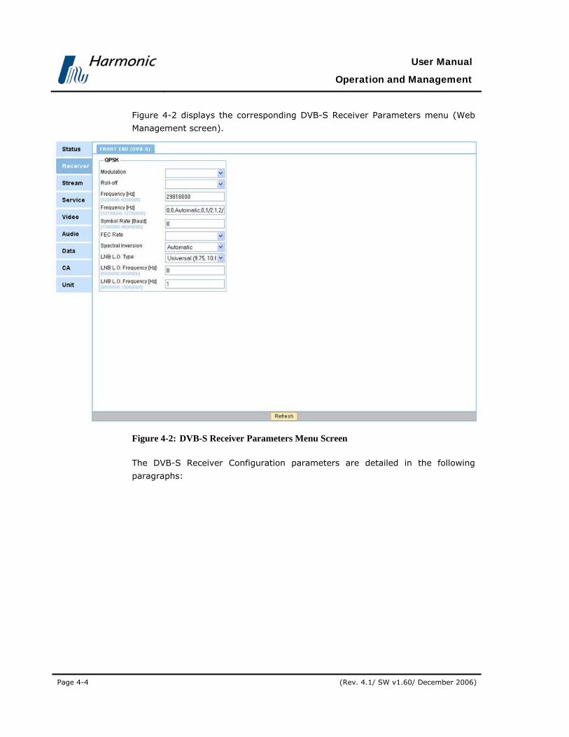
User Manual
Operation and Management
Page 4-4 (Rev. 4.1/ SW v1.60/ December 2006)
Figure 4-2 displays the corresponding DVB-S Receiver Parameters menu (Web
Management screen).
Figure 4-2: DVB-S Receiver Parameters Menu Screen
The DVB-S Receiver Configuration parameters are detailed in the following
paragraphs:

PVR 6000 Series
Professional Integrated Receiver Decoders
Page 4-5
FREQUENCY The Frequency parameter must be set in accordance with the required satellite
transponder frequency. The frequency can be acquired from the satellite
transponder information.
In this example, the valid frequency range is between 0.95 and 2.15GHz.
Frequency
1.068000 [GHz]
<0.950000 - 2.150000>
The valid frequency range varies according to the selected band.
Table 4-1: Band Frequency Range
BAND MINIMUM FREQUENCY MAXIMUM FREQUENCY
Ku-Band 10.700000GHz 12.750000GHz
C-Band 3.200000GHz 4.200000GHz
L-Band 0.950000GHz 2.150000GHz
SYMBOL RATE The Symbol Rate parameter must be set according to the satellite transponder
symbol rate. The Symbol Rate value can be acquired from the satellite
transponder information or can be calculated, with the bit rate information.
Symbol Rate
29.818000 [Mbaud]
<01.000000 - 45.000000>
Available values range from 01.000000 to 45.000000 Mbaud.
NOTE
It is important to input the accurate Symbol Rate down to the sixth digit after
the decimal point.

User Manual
Operation and Management
Page 4-6 (Rev. 4.1/ SW v1.60/ December 2006)
FEC RATE The FEC Rate parameter sets the Forward error correction rate value. The FEC
parameter can be acquired from the satellite transponder information or can be
set to automatic. When in Automatic mode, the PVR 6000 device tries all FEC
rates until locking the rate to the transport stream.
FEC Rate
1 AUTOMATIC
2 1/2
3 2/3
4 3/4
5 5/6
6 7/8
The available options are:
• Automatic • 3/4
• 1/2 • 5/6
• 2/3 • 7/8
NOTE
If the specific Viterbi rate is not provided, selecting the Automatic option enables
the PVR 6000 to automatically detect the Viterbi rate.

PVR 6000 Series
Professional Integrated Receiver Decoders
Page 4-7
SPECTRAL INVERSION The Spectral Inversion parameter sets the spectral mode of operation. This
parameter is configured according to the information provided from the
broadcast head-end or can be set to automatic.
When set to automatic mode, the PVR 6000 tries the two spectral modes until
obtaining synchronization.
Spectral Inversion
1 AUTOMATIC
2 INVERTED
3 NORMAL
The available options are:
• AUTOMATIC – Automatically selects between Normal and Inverted spectral
mode
• INVERTED – Inverted spectral mode
• NORMAL – Normal spectral mode
LNB POWER SUPPLY The PVR 6000 sets the polarization of the receiving antenna by providing
different voltage levels to the LNB, 13v for vertical polarization and 18v for
horizontal polarization.
The polarization of the receiving antenna is determined according to the polarity
of the satellite transponder.
LNB Power Supply
1 13V (VERTICAL)
2 18V (HORIZONTAL)
3 OFF
The available options are:
• OFF - No voltage is supplied to the LNB. Use this option either when
cascading IRDs using the loop-through connector on the L-Band interface or
when this voltage is supplied to the LNB by external source.
• 13V (VERTICAL) – Vertical polarization
• 18V (HORIZONTAL) – Horizontal polarization

User Manual
Operation and Management
Page 4-8 (Rev. 4.1/ SW v1.60/ December 2006)
LNB 22 KHZ The receiver controls the LNB band by sending a 22 kHz signal. When the signal
is sent, the LNB uses its High Band Local Oscillator (L.O.). When the signal is not
sent, the LNB uses its Low Band L.O.
The local oscillator is used to convert the signal from Ku-Band or C-Band to L-
Band. Two local oscillators exist one for each band to leverage full spectrum.
LNB 22 KHz
1 OFF (Low Band)
2 ON (High Band)
The available options are:
• OFF – Low band L.O.
• ON – High band L.O.
FREQ DRIFT COMPENSATION The PVR 6000 uses Freq Drift Compensation to automatically correct
inaccurate frequencies set by the operator.
When the operator sets the receiver frequency, the PVR 6000 checks whether it
is set to the optimum frequency. When a deviation is detected, the PVR 6000
calculates the offset from the original setting and enables correcting it.
Turning on the Freq Drift Compensation activates the automatic frequency
adjustment. When Drift compensation is turned off, the device uses the original
frequency setting that was inserted by the operator.
Freq Drift Compensation
1 OFF
2 ON
The available options are:
• OFF – Drift Compensation is off; the receiver remains with the configured
frequency.
• ON - Drift Compensation is on; the receiver adjusts its optimal frequency.
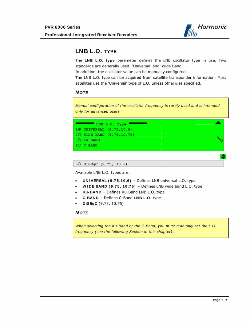
PVR 6000 Series
Professional Integrated Receiver Decoders
Page 4-9
LNB L.O. TYPE The LNB L.O. type parameter defines the LNB oscillator type in use. Two
standards are generally used: ‘Universal’ and ‘Wide Band’.
In addition, the oscillator value can be manually configured.
The LNB L.O. type can be acquired from satellite transponder information. Most
satellites use the ‘Universal’ type of L.O. unless otherwise specified.
NOTE
Manual configuration of the oscillator frequency is rarely used and is intended
only for advanced users.
LNB L.O. Type
1 UNIVERSAL (9.75,10.6)
2 WIDE BAND (9.75,10.75)
3 Ku BAND
4 C BAND
5 DiSEqC (9.75, 10.6)
Available LNB L.O. types are:
• UNIVERSAL (9.75,10.6) – Defines LNB universal L.O. type
• WIDE BAND (9.75, 10.75) – Defines LNB wide band L.O. type
• Ku-BAND – Defines Ku-Band LNB L.O. type
• C-BAND – Defines C-Band LNB L.O. type
• DiSEqC (9.75, 10.75)
NOTE
When selecting the Ku-Band or the C-Band, you must manually set the L.O.
frequency (see the following Section in this chapter).

User Manual
Operation and Management
Page 4-10 (Rev. 4.1/ SW v1.60/ December 2006)
FREQUENCY RANGE The Frequency Range parameter defines the input frequency in the Ku, C or L
bands.
This parameter affects the displayed frequencies and ranges of the PVR 6000
DVB-S receiver parameters.
Frequency Range
1 L BAND
2 Ku BAND
3 C BAND
The available options are:
• L-BAND – Receiving in the L-Band frequency range
• Ku-BAND – Receiving in the Ku-Band frequency range
• C-BAND – Receiving in the C-Band frequency range
FREQUENCY BAND SCAN The Frequency Band Scan command allows scanning the selected frequency
range if the frequency is unknown. The symbol rate must be known and set in
the IRD. The PVR 6000 scans the frequency range, while seeking a valid DVB
stream. Upon locating a valid DVB stream, the PVR 6000 marks the located
frequency and service name. Results output either to the RS-232 port (terminal)
or Telnet. The following screen displays the Frequency Band Scan Screen
NOTE
The PVR 6000 scans only the L-band frequency range. Located frequencies are
shown in L-Band and must be modified for the relevant frequency value if they
are tuned to either C-band or Ku-band.
Frequency Band Scan
1 OFF
2 ON
The available options are:
• OFF – Frequency scan is disabled
• ON – Frequency scan is enabled

PVR 6000 Series
Professional Integrated Receiver Decoders
Page 4-11
4.2.2.2. DVB-S2 Receiver Configuration
This section details the front panel menus that enable configuring the DVB-S2
receiver in an PVR 6000 DVB-S2 front end device.
The following is a screen of the DVB-S2 Receiver Configuration menu as
displayed on the front panel screen:
Receiver 1-2-1
01 Frequency 1.000000 [GHz]
02 Symbol Rate 27.000000 [Mbaud]
03 Modulation DVB-S2-N-QPSK
04 Roll-off 35%
05 Pilots ON
06 FEC Rate 8/9
07 Spectral Inversion AUTOMATIC
08 LNB Power Supply 18V (HORIZONTAL)
09 LNB 22 KHz OFF (Low Band)
10 Input Serial Source IN-B
11 Freq Drift Compensation OFF]
12 LNB L.O. Type UNIVERSAL <9.75,...
13 Frequency Range L BAND
14 Frequency Band Scan OFF

User Manual
Operation and Management
Page 4-12 (Rev. 4.1/ SW v1.60/ December 2006)
Figure 4-3 displays the corresponding DVB-S2 Receiver Parameters menu (Web
Management screen).
Figure 4-3: DVB-S2 Receiver Parameters Menu Screen
The DVB-S2 Receiver Configuration parameters are detailed as follows:
FREQUENCY The Frequency menu is used for tuning the PVR 6000 receiver to the relevant
satellite frequency.
Frequency
[GHz]
<0.950000 - 2.150000>
The displayed frequency range corresponds with the frequency band that is
currently selected.

PVR 6000 Series
Professional Integrated Receiver Decoders
Page 4-13
Table 4-2 lists the different bands, and their respective frequency ranges.
Table 4-2: Band Frequency Designations
BAND FREQUENCY
L-Band 0.950000-2.150000GHz
C-Band 3.200000-4.200000GHz
Ku-Band 10.700000-12.750000GHz
SYMBOL RATE The Symbol Rate menu is used for adjusting the receiver’s symbol rate to the
symbol rate of the received signal.
Symbol Rate
27.000000 [Mbaud]
<00.016000 – 45.000000>
Available values range from 00.016000 to 45.000000 Mbaud
NOTE
The symbol rate must be set to match the exact symbol rate value used by the
satellite transponder.
MODULATION The Modulation menu allows setting the PVR 6000 receiver to the relevant
modulation method.
Modulation
1 DVBS-QPSK
2 DSNG-8PSK
3 DSNG-16QAM
4 DVBS2-N-QPSK

User Manual
Operation and Management
Page 4-14 (Rev. 4.1/ SW v1.60/ December 2006)
5 DVBS2-N- 8PSK
6 DVBS2-N-16APSK
7 DVBS2-S-QPSK
8 DVBS2-S-8PSK
9 DVBS2-S-16APSK
Available modulation options are:
• DVBS-QPSK
• DSNG-8PSK
• DSNG-16QAM
• DVBS2-N-QPSK
• DVBS2-N-8PSK
• DVBS2-N-16APSK
• DVBS2-S-QPSK
• DVBS2-S-8PSK
• DVBS2-S-16APSK
ROLL- OFF The Roll off menu is used for setting the receiver’s roll-off factor value
according to the roll-off factor of the transmitted signal.
The Roll-off factor is the factor that is used for the base-band shaping of the
transmitted signal. Set the Roll-Off factor in accordance with the transmitted
Roll-Off factor.
Roll-off
1 35%
2 25%
3 20%
Available options for the Roll-off factor are:
• 35%
• 25%
• 20%
PILOTS
In order to expedite carrier recovery, the standard allows two operating modes for
each modulation type: Pilot-less (i.e. no Pilot symbols are inserted) and Piloted,
where Pilot symbols are inserted to aid carrier synchronization. The Pilots menu
enables to choose between the two operating modss.

PVR 6000 Series
Professional Integrated Receiver Decoders
Page 4-15
Pilots
1 OFF
2 ON
The available options are:
• OFF – selects Pilot-less mode
• ON - selects Piloted mode
NOTE
The PLSCODE informs the receiver regarding the pilot configuration, which
resides in the PLHEADER. Usually, only a few modes, such as 8PSK rate 2/3,
16APSK rate 2/3 and 3/4, and 32APSK rate 3/4, need pilot assistance for carrier
recovery.
FEC RATE The FEC Rate menu enables to set the Forward Error Correction rate according
to the FEC rate of the transmitted signal.
FEC Rate
01 1/4
02 1/3
03 2/5
04 1/2
05 3/5
06 2/3
07 3/4
08 4/5
09 5/6
10 7/8
11 8/9
12 9/10

User Manual
Operation and Management
Page 4-16 (Rev. 4.1/ SW v1.60/ December 2006)
Available FEC rates are:
• 1/4
• 1/3
• 2/5
• 1/2
• 3/5
• 2/3
• 3/4
• 4/5
• 5/6
• 7/8
• 8/9
• 9/10
SPECTRAL INVERSION The Spectral Inversion menu is used for setting the spectral inversion mode.
Spectral Inversion
1 AUTOMATIC
2 INVERTED
3 NORMAL
The available options are:
• AUTOMATIC – the PVR 6000 automatically detects and sets the Spectral
Inversion Mode
• INVERTED – sets the PVR 6000 receiver to “inverted” Spectral Inversion
Mode.
• NORMAL - sets the PVR 6000 receiver to normal Spectral Inversion Mode.
LNB POWER SUPPLY The LNB Power Supply menu is used for setting the power supply voltage level
to the LNB in order to control the received signal polarization.
LNB Power Supply
1 13V (VERTICAL)
2 18V (HORIZONTAL)
3 OFF
The available options are:
• 13V (VERTICAL) – sets the LNB polarization to vertical
• 18V (HORIZONTAL) - sets the LNB polarization to horizontal
• OFF –power to the LNB is disabled.

PVR 6000 Series
Professional Integrated Receiver Decoders
Page 4-17
LNB 22KHZ The LNB-22KHz menu enables selecting between LNB low band and high band
reception, by generating a 22 kHz signal that is sent to the LNB for this purpose.
LNB 22KHz
1 OFF (Low Band)
2 ON (High Band)
The available options are:
• OFF (Low Band) – the 22 kHz signal is not generated, and low band
reception is selected
• ON (High Band) - the 22 kHz signal is generated and high band reception
is selected.
INPUT SIGNAL SOURCE The Input Signal Source menu selects the RF interface source through which
to acquire the signal to be received. This menu exists only in Dual RF Input PVR
6000 devices.
Input Signal Source
1 IN-A
2 IN-B
The available options are:
• IN-A – the PVR 6000 receives the input signal from RF IN 1 interface
• IN-B - the PVR 6000 receives the input signal from RF IN 2 interface

User Manual
Operation and Management
Page 4-18 (Rev. 4.1/ SW v1.60/ December 2006)
FREQ DRIFT COMPENSATION The PVR 6000 uses Freq Drift Compensation Feature to automatically correct
inaccurate frequencies inserted by the operator.
When the operator sets the receiver frequency, the PVR 6000 checks whether
the inserted frequency is set to the optimal frequency. When a deviation is
detected, the PVR 6000 calculates the offset from the original setting and
enables correcting it.
Turning on the Freq Drift Compensation in the following menu activates the
automatic frequency adjustment. When Drift compensation is turned off, the
device uses the original frequency setting that was inserted by the operator.
Freq Drift Compensation
1 OFF
2 ON
The available options are:
• OFF – Drift Compensation is off; the receiver remains tuned to the
configured frequency.
• ON - Drift Compensation is on; the receiver tunes to the optimum
frequency.
LNB L.O. TYPE The LNB L.O. Type menu enables selecting the type of installed LNB.
LNB L.O. Type
1 UNIVERSAL (9.75, 10.6)
2 WIDE BAND (9.75, 10.75)
3 Ku BAND
4 C BAND
05 DiSEqC (9.75, 10.6)
The available options are:
• UNIVERSAL (9.75, 10.6)
• WIDE BAND (9.75, 10.75)
• Ku BAND
• C BAND
• DiSEqC (9.75, 10.6)

PVR 6000 Series
Professional Integrated Receiver Decoders
Page 4-19
FREQUENCY RANGE The Frequency Range menu is used for selecting the receiver’s active
frequency band.
Frequency Range
1 L BAND
2 Ku BAND
3 C BAND
Available frequency band options are:
• L BAND – selects the frequency range 0.950000 - 2.150000 GHz
• Ku BAND - selects the frequency range 3.200000 - 4.200000 GHz
• C BAND - selects the frequency range 10.700000 - 12.750000 GHz
FREQUENCY BAND SCAN The Frequency Band Scan menu is used for mapping all the available
transmission frequencies received by the antenna. The symbol rate during the
scan is constant and must be set according to the satellite’s symbol rate. Upon
locating a valid DVB stream, the PVR 6000 logs the located frequency and
service name and outputs the log through the RS232 port (terminal) or through
Telnet.
Frequency Band Scan
1 OFF
2 ON
The available options are:
• OFF – band scan is disabled
• ON – starts the band scan

User Manual
Operation and Management
Page 4-20 (Rev. 4.1/ SW v1.60/ December 2006)
4.2.2.3. DVB-DSNG Module
This section details the front panel menus that enable configuring the DVB-
DSNG receiver in an PVR 6000 DVB-DSNG front end device.
The following is the DVB-DSNG Receiver Configuration menu as displayed on
the PVR 6000 front panel screen:
Receiver 1-2-1
01 Frequency 1.138000[GHz]
02 Symbol Rate 29.575707[Mbaud]
03 Modulations AUTOMATIC
04 Roll off AUTOMATIC
05 FEC Rate AUTOMATIC
06 Spectral Inversion AUTOMATIC
07 LNB Power Supply 18V(Horizontal)
08 LNB 22Hz OFF(Low Band)
09 Input Serial Source IN-A
10 Freq Drift Correction OFF
11 LNB L.O Type UNIVERSAL(9.75...
12 Frequency Range L BAND
13 Frequency Band Scan OFF

PVR 6000 Series
Professional Integrated Receiver Decoders
Page 4-21
Figure 4-4 displays the corresponding DVB-DSNG receiver parameters menu
(Web Management screen).
Figure 4-4: DVB-DSNG Receiver Parameters Menu Screen
FREQUENCY The Frequency parameter must be set in accordance with the required satellite
transponder frequency. The frequency can be acquired from the satellite
transponder information.
In this example, the valid frequency range is between 0.95 and 2.15GHz.
Frequency
1.068000 [GHz]
<0.950000 - 2.150000>

User Manual
Operation and Management
Page 4-22 (Rev. 4.1/ SW v1.60/ December 2006)
The valid frequency range varies according to the selected band.
Table 4-3: Band Frequency Range
BAND MINIMUM FREQUENCY MAXIMUM FREQUENCY
Ku-Band 10.700000GHz 12.750000GHz
C-Band 3.200000GHz 4.200000GHz
L-Band 0.950000GHz 2.150000GHz
SYMBOL RATE The Symbol Rate parameter must be set according to the satellite transponder
symbol rate. The Symbol Rate value can be acquired from the satellite
transponder information or can be calculated, with the bit rate information.
Symbol Rate
29.818000 [Mbaud]
<01.000000 - 45.000000>
Available values range from 01.000000 to 45.000000 Mbaud.
NOTE
It is important to input the accurate Symbol Rate down to the sixth digit after
the decimal point.
MODULATION The Modulation menu allows setting the PVR 6000 receiver to the relevant
modulation method.
Modulation
1 AUTOMATIC
2 DVBS-QPSK
3 DVBS-8PSK
4 DSNG-16QAM
ROLL- OFF The Roll off menu is used for setting the receiver’s roll-off factor value
according to the roll-off factor of the transmitted signal.

PVR 6000 Series
Professional Integrated Receiver Decoders
Page 4-23
The Roll-off factor is the factor that is used for the base-band shaping of the
transmitted signal. Set the Roll-Off factor in accordance with the transmitted
Roll-Off factor.
Roll-off
1 AUTOMATIC
2 35%
3 25%
Available options for the Roll-off factor are:
• 35%, 25%, 20%
FEC RATE The FEC Rate parameter sets the Forward error correction rate value. The FEC
parameter can be acquired from the satellite transponder information or can be
set to automatic. When in Automatic mode, the PVR 6000 device tries all FEC
rates until locking the rate to the transport stream.
FEC Rate
1 AUTOMATIC
2 1/2
3 2/3
4 3/4
5 5/6
6 7/8
6 8/9
The available options are:
• Automatic
• 1/2
• 2/3
• 3/4
• 5/6
• 7/8
• 8/9

User Manual
Operation and Management
Page 4-24 (Rev. 4.1/ SW v1.60/ December 2006)
NOTE
If the specific Viterbi rate is not provided, selecting the Automatic option enables
the PVR 6000 to automatically detect the Viterbi rate.
SPECTRAL INVERSION The Spectral Inversion parameter sets the spectral mode of operation. This
parameter is configured according to the information provided from the
broadcast head-end or can be set to automatic.
When set to automatic mode, the PVR 6000 tries the two spectral modes until
obtaining synchronization.
Spectral Inversion
1 AUTOMATIC
2 INVERTED
3 NORMAL
The available options are:
• Automatic – Automatically selects between Normal and Inverted spectral
mode
• INVERTED – Inverted spectral mode
• NORMAL – Normal spectral mode
LNB POWER SUPPLY The PVR 6000 sets the polarization of the receiving antenna by providing
different voltage levels to the LNB, 13v for vertical polarization and 18v for
horizontal polarization.
The polarization of the receiving antenna is determined according to the polarity
of the satellite transponder.
LNB Power Supply
1 13V (VERTICAL)
2 18V (HORIZONTAL)
3 OFF

PVR 6000 Series
Professional Integrated Receiver Decoders
Page 4-25
The available options are:
• OFF – No voltage is supplied to the LNB. Use this option either when
cascading IRDs using the loop-through connector on the L-Band interface or
when this voltage is supplied to the LNB by external source.
• 13V (Vertical) – Vertical polarization
• 18V (Horizontal) – Horizontal polarization
LNB 22 KHZ The receiver controls the LNB band by sending a 22 kHz signal. When the signal
is sent, the LNB uses its High Band Local Oscillator (L.O.). When the signal is not
sent, the LNB uses its Low Band L.O.
The local oscillator is used to convert the signal from Ku-Band or C-Band to L-
Band. Two local oscillators exist one for each band to leverage full spectrum.
LNB 22 KHz
1 OFF (Low Band)
2 ON (High Band)
The available options are:
• OFF – Low band L.O.
• ON – High band L.O.
INPUT SIGNAL SOURCE The Input Signal Source menu selects the RF interface source through which
to acquire the signal to be received. This menu exists only in Dual RF Input PVR
6000 devices.
Input Signal Source
1 IN-A
2 IN-B
The available options are:
• IN-A – the PVR 6000 receives the input signal from RF IN 1 interface
• IN-B - the PVR 6000 receives the input signal from RF IN 2 interface

User Manual
Operation and Management
Page 4-26 (Rev. 4.1/ SW v1.60/ December 2006)
FREQ DRIFT COMPENSATION The PVR 6000 uses Freq Drift Compensation to automatically correct
inaccurate frequencies set by the operator.
When the operator sets the receiver frequency, the PVR 6000 checks whether it
is set to the optimum frequency. When a deviation is detected, the PVR 6000
calculates the offset from the original setting and enables correcting it.
Turning on the Freq Drift Compensation activates the automatic frequency
adjustment. When Drift compensation is turned off, the device uses the original
frequency setting that was inserted by the operator.
Freq Drift Compensation
1 OFF
2 ON
The available options are:
• OFF – Drift Compensation is off; the receiver remains with the configured
frequency.
• ON - Drift Compensation is on; the receiver adjusts its optimal frequency.
4.2.2.4. DVB-ATM Module
This section details the front panel menus that enable configuring the DVB-ATM
receiver in a PVR 6000 DVB-ATM front end device.
The following is the DVB-ATM Receiver Configuration menu as displayed on
the PVR 6000 front panel screen:
General
1-2-1
1 Mode
DS3
2 VPI Address
01
2 VCI Address
0020
4 FEC
ENABLE
The available options are:
• Mode – this parameter allows the user to set the operational mode of the ATM receiver.
• VPI Address –this parameter allows the user to set the path address for the ATM receiver.
• VCI Address – this parameter allows the user to set the channel address for the ATM receiver.

PVR 6000 Series
Professional Integrated Receiver Decoders
Page 4-27
• FEC – this parameter allows the user to enable FEC for the ATM receiver.
MODE The Mode parameter allows the user to set the operational mode of the ATM
receiver. The following is the front panel Mode screen:
Mode
1 E3
2 DS3
2 STM-1 MULTI MODE
4 STM-1 SINGLE MODE
5 OC-3 MULTI MODE
6 OC-3 SINGLE MODE
VPI ADDRESS The VPI Address parameter allows the user to set the path address for the ATM
receiver. The following is the front panel VPI Address screen:
VPI Address
01[Hex]
<00-FF>
The available values range from 00 to FF.
VCI ADDRESS The VCI Address parameter allows the user to set the channel address for the
ATM receiver. The following is the front panel VCI Address screen:
VPI Address
0020[Hex]
<0000-FFFF>
The available values range from 00 to FF.
FEC The FEC parameter allows the user to enable or disable FEC for the ATM
receiver. The following is the front panel FEC screen:

User Manual
Operation and Management
Page 4-28 (Rev. 4.1/ SW v1.60/ December 2006)
VPI Address
1 Enable
2 Disable
4.2.2.5. IP Receiver Configuration Menu
This section details the front panel menus that enable configuring the IP receiver
in a PVR 6000 IP front end device.
The following is the IP Receiver Configuration menu as it is displayed on the
PVR 6000 front panel screen:
Receiver 1-2-1
1 MPEGoIP Input 1
2 MPEGoIP Input 2
3 General
The available options are:
• MPEGoIP Input 1 - allows the user to configure the MPEGoIP receiver
connected to the rear panel MPEGoIP IN 1 interface
• MPEGoIP Input 2- allows the user to configure the MPEGoIP receiver
connected to the rear panel MPEGoIP IN 2 interface
• General - allows the user to configure parameters such as redundancy, De-
jittering delay, and FEC.
MPEGOIP INPUT 1 The MPEGo-IP Input 1 sub-menu allows the user to configure the MPEGoIP
receiver connected to the rear panel MPEGoIP interface.
NOTE
MPEGoIP Input 2 menu is identical to the MPEGoIP Input 1 menu
MPEGoIP Input 1 1-2-1-1
1 Physical Link 2 Logical Source 3 FEC

PVR 6000 Series
Professional Integrated Receiver Decoders
Page 4-29
Figure 4-5 displays the corresponding DVB-IP Receiver MPEGoIP 1 Parameters
Menu (Web Management screen).
Figure 4-5: DVB-IP Receiver – MPEGoIP 1 Parameters Menu Screen
The available options are:
• Physical Link – for configuring this physical link parameters
• Logical Source (Socket) – for configuring the IP parameters of the TS
source end-device (“logical port” parameters)
• FEC – for configuring the Forward Error Correction parameters the three
options are detailed follows.
The three options are detailed as follows:

User Manual
Operation and Management
Page 4-30 (Rev. 4.1/ SW v1.60/ December 2006)
PHYSICAL LINK The physical Link menu is used for enabling the operation of the physical link
(the MPEGoIP IN1 interface in this example), as well as for configuring its
parameters.
Physical Link 1-2-1-1-1
01 Operation DISABLE
02 IP Address 010.006.000.196
03 Subnet Mask 255.255.255.000
04 Default Gateway 010.006.000.001
Available options are
• Operation - for enabling or disabling this port
• IP Address - this MPEGoIP input port’s IP address
• Subnet Mask - this MPEGoIP input port’s Subnet Mask
• Default Gateway - the default gateway address
NOTE
The operator must enter valid IP addresses before the PVR 6000 can operate. If
one or more IP addresses are not entered correctly, the following message is
displayed: “Front-End Warning – IP Configuration Error”. This message
remains until all IP addresses are entered correctly.
OPERATION The Operation menu is used for enabling or disabling this MPEGoIP input port.
Operation
1 ENABLE
2 DISABLE
The available options are:
• ENABLE – enables the relevant MPEGoIP input (MPEGoIP IN1 in this
example)
• DISABLE - disables the relevant MPEGoIP input (MPEGoIP IN1 in this
example).

PVR 6000 Series
Professional Integrated Receiver Decoders
Page 4-31
IP ADDRESS The IP Address menu is used for setting the IP address of this physical
MPEGoIP input port (MPEGoIP IN1 in this example)
IP Address
010.006.000.196
Use the front panel right/left arrows to navigate between the digits locations,
and the up/down arrows to toggle the digits for creating the address.
NETWORK MASK The Network Mask menu is used for setting the Network Subnet Mask of the
physical MPEGoIP input port (MPEGoIP IN1 in this example)
Network Mask
255.255.255.000
Use the front panel right/left arrows to navigate between the digits locations and
the up/down arrows to toggle the digits for creating the address.
DEFAULT GATEWAY The Default Gateway menu is used for setting the default gateway address for
the PVR 6000’s physical MPEGoIP input port
Default Gateway
010.006.000.001
Use the front panel right/left arrows to navigate between the digits locations,
and the up/down arrows to toggle the digits for creating the address.
NOTE
Both MPEGoIP input ports must use the same gateway.

User Manual
Operation and Management
Page 4-32 (Rev. 4.1/ SW v1.60/ December 2006)
LOGICAL SOURCE (SOCKET) The Logical source menu is used for configuring the connection with the end
device (“logical port”).
Logical Source 1-2-1-1-2
01 IP Address Type MULTICAST
02 IP Multicast Address 224.010.010.010
03 UDP Destination Port 02000
The available options are:
• IP Address Type - for choosing between Multicast and Unicast address
types
• IP Multicast Address - the logical port’s IP address (this menu is displayed
only when Multicast IP address type is selected)
• UDP Destination Port - the logical port’s UDP port from which to receive
data
IP ADDRESS TYPE This menu is used for choosing the Multicast or Unicast address type.
IP Address Type
1 MULTICAST
2 UNICAST
The available options are:
• MULTICAST – for selecting Multicast IP address type. When selected, the IP
Multicast address menu is displayed, which enables configuring the Multicast
address. An IGMP Join request is sent for connecting with the IP Multicast
address that was configured. The PVR 6000 filters the relevant transport
stream with the configured Multicast IP address and UDP port.
• UNICAST - for selecting Unicast IP address type. The PVR 6000 filters the
relevant transport stream only by the configured UDP port.

PVR 6000 Series
Professional Integrated Receiver Decoders
Page 4-33
IP MULTICAST ADDRESS The IP Multicast Address menu enables setting the logical port’s IP address
(this menu is displayed only when the Multicast IP address type is selected).
IP Multicast Address
224.010.010.010
Use the front panel right/left arrows to navigate between the digits locations,
and the up/down arrows to toggle the digits for creating the address.
UDP DESTINATION PORT The UDP Destination Port menu enables setting the logical port’s UDP port
number
UDP Destination Port
02000
< 00000 - 65535 >
Use the front panel right/left arrows to navigate between the digits locations and
the up/down arrows to toggle the digits for creating the address.
FEC (FORWARD ERROR CORRECTION) The PVR 6000 IP Front End-FEC Implementation complies with ProMPEG
CoP3v2, with the following limitations:
• Columns support only
• Maximum TS bit-rate - 20 Mbps
FEC 1-2-1-1-3
1 FEC Column Port 02002
Selecting FEC Column Port displays the following screen, which allows setting
the UDP port number carrying the FEC data.
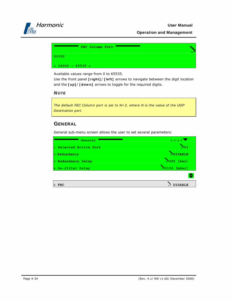
User Manual
Operation and Management
Page 4-34 (Rev. 4.1/ SW v1.60/ December 2006)
FEC Column Port
02002
< 00000 – 65535 >
Available values range from 0 to 65535.
Use the front panel [right]/ [left] arrows to navigate between the digit location
and the [up]/ [down] arrows to toggle for the required digits.
NOTE
The default FEC Column port is set to N+2, where N is the value of the UDP
Destination port.
GENERAL General sub-menu screen allows the user to set several parameters:
General 1-2-1-3
1 Selected Active Port 01
2 Redundancy DISABLE
3 Redundancy Delay 005 [Sec]
4 De-Jitter Delay 0100 [mSec]
5 FEC DISABLE

PVR 6000 Series
Professional Integrated Receiver Decoders
Page 4-35
Figure 4-6 displays the corresponding DVB-IP Receiver General Parameters
Menu (Web Management screen).
Figure 4-6: DVB-IP Receiver – General Parameters Menu Screen
• Selected Active Port – for selecting the active input port. This port will
become active and remain active unless a redundancy event caused the PVR
6000 to switch to the other input port.
• Redundancy - enables or disables the PVR 6000 redundancy feature
• Redundancy Delay - for setting the time delay that defines a redundancy
event
• De-Jitter Delay - for setting the de-jitter buffer time delay
• FEC – enables or disables the FEC feature
SELECTED ACTIVE PORT The Selected Active Port menu is used for selecting the active input port. This
port will become active, and remain active unless a redundancy event caused
the PVR 6000 to switch to the other input port.
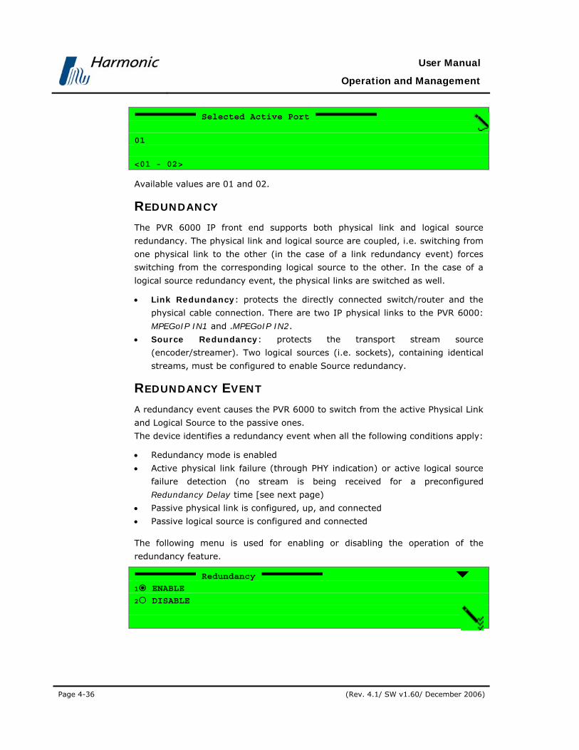
User Manual
Operation and Management
Page 4-36 (Rev. 4.1/ SW v1.60/ December 2006)
Selected Active Port
01
<01 - 02>
Available values are 01 and 02.
REDUNDANCY The PVR 6000 IP front end supports both physical link and logical source
redundancy. The physical link and logical source are coupled, i.e. switching from
one physical link to the other (in the case of a link redundancy event) forces
switching from the corresponding logical source to the other. In the case of a
logical source redundancy event, the physical links are switched as well.
• Link Redundancy: protects the directly connected switch/router and the
physical cable connection. There are two IP physical links to the PVR 6000:
MPEGoIP IN1 and .MPEGoIP IN2.
• Source Redundancy: protects the transport stream source
(encoder/streamer). Two logical sources (i.e. sockets), containing identical
streams, must be configured to enable Source redundancy.
REDUNDANCY EVENT A redundancy event causes the PVR 6000 to switch from the active Physical Link
and Logical Source to the passive ones.
The device identifies a redundancy event when all the following conditions apply:
• Redundancy mode is enabled
• Active physical link failure (through PHY indication) or active logical source
failure detection (no stream is being received for a preconfigured
Redundancy Delay time [see next page)
• Passive physical link is configured, up, and connected
• Passive logical source is configured and connected
The following menu is used for enabling or disabling the operation of the
redundancy feature.
Redundancy
1 ENABLE
2 DISABLE

PVR 6000 Series
Professional Integrated Receiver Decoders
Page 4-37
The available options are:
• ENABLE – enables redundancy; when a redundancy event occurs the
physical link and logical source switch to passive ones
• DISABLE - disables redundancy
REDUNDANCY DELAY The Redundancy delay menu is used for setting the time delay, which defines
a redundancy event.
Redundancy Delay
005 [Sec]
<000 - 255>
Redundancy delay values range from 0 to 255 seconds.
DE-JITTER DELAY The De-jitter Delay menu is used for setting the decoder’s De-Jitter delay in
milliseconds.
The aim of the De-Jittering mechanism is to eliminate the inherent jitter
introduced by a typical IP network. This mechanism practically acquires the
source exact frequency and follows it. The PVR 6000 supports de-jittering of CBR
(Constant Bit Rate) streams.
The de-jitter delay configurability enables only optimizing unit-performance
according to specific needs. The longer the delay, the longer the jitter that can
be eliminated (traded off by longer latency).
De-Jitter Delay
0100 [mSec]
<0000 - 6000>
De-jitter delay values range from 0 to 6000 milliseconds.

User Manual
Operation and Management
Page 4-38 (Rev. 4.1/ SW v1.60/ December 2006)
FEC The PVR 6000 IP Front End FEC Implementation complies with ProMPEG
CoP3v2, with the following limitations:
• Columns support only
• Maximum TS bit-rate: 25 Mbps
This menu enables OR disables FEC operation.
FEC
1 ENABLE
2 DISABLE
The available options are:
• ENABLE – enables FEC operation; regenerates missing IP packets using FEC
packets received from the configured UDP port.
• DISABLE - disables FEC operation; ignores FEC packets and does not
regenerate missing IP packets.

PVR 6000 Series
Professional Integrated Receiver Decoders
Page 4-39
4.2.3. Stream Configuration Menu To access the Stream Configuration Menu in the front panel control interface
go to Configuration Stream.
Figure 4-7 displays a tree diagram of the Stream Configuration Menu.
Figure 4-7: Stream Configuration Menu
The following figure displays the Stream configuration menu:
Stream 1-2-2
1 Input
2 Output
3 Clock
4 Filtering

User Manual
Operation and Management
Page 4-40 (Rev. 4.1/ SW v1.60/ December 2006)
Figure 4-8 displays the corresponding Stream configuration (Web Management
screen).
Figure 4-8: Stream Parameters Menu Screen
The following Sections detail the Stream Configuration parameters.
4.2.3.1. Input
The PVR 6000 supports a wide range of optional input interfaces, allowing the
PVR 6000 to receive input streams from different sources.
Input
1 Source 2 Type
3 Rate Range
4 ASI Mode
The Source parameter defines the input stream source.
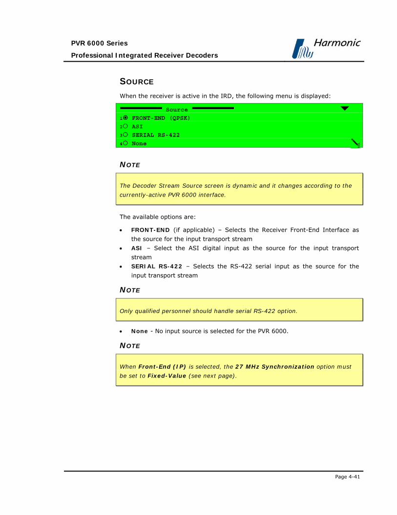
PVR 6000 Series
Professional Integrated Receiver Decoders
Page 4-41
SOURCE When the receiver is active in the IRD, the following menu is displayed:
Source
1 FRONT-END (QPSK)
2 ASI
3 SERIAL RS-422
4 None
NOTE
The Decoder Stream Source screen is dynamic and it changes according to the
currently-active PVR 6000 interface.
The available options are:
• FRONT-END (if applicable) – Selects the Receiver Front-End Interface as
the source for the input transport stream
• ASI – Select the ASI digital input as the source for the input transport
stream
• SERIAL RS-422 – Selects the RS-422 serial input as the source for the
input transport stream
NOTE
Only qualified personnel should handle serial RS-422 option.
• None - No input source is selected for the PVR 6000.
NOTE
When Front-End (IP) is selected, the 27 MHz Synchronization option must
be set to Fixed-Value (see next page).

User Manual
Operation and Management
Page 4-42 (Rev. 4.1/ SW v1.60/ December 2006)
TYPE The Type parameter allows selecting between ATSC format and DVB format.
Type
1 ATSC
2 DVB
RATE RANGE The Rate Range parameter defines the range of the ASI input rates.
Rate Range
1 UPTO 72Mb/s
2 UPTO 108Mb/s
3 ABOVE 108Mb/s
The available options are:
• UPTO 72Mb/s – Selected when using a CAM for descrambling
• UPTO 108Mb/s – Selected when not using CAM and inputting a transport
Stream within a rate of 72M-108Mb/s.
• ABOVE 108Mb/s – Not in use.
NOTE
The ASI Input-Rate Range parameter in the front panel interface corresponds
with Stream Rate Range in the Web management interface (see Figure 4-8).
ASI MODE The ASI Mode parameter allows selecting between BURST format and NORMAL
format.

PVR 6000 Series
Professional Integrated Receiver Decoders
Page 4-43
Type
1 BURST
2 NORMAL
4.2.3.2. Output
The PVR 6000 supports a wide range of optional output interfaces, allowing the
PVR 6000 to send output streams to different destinations.
Output
1 ASI Output Source
2 IP Output Source
The ASI Output Source parameter defines the type of ASI output source.
ASI Output Source
1 DECODER SOURCE
2 AFTER DECRYPTION
3 AFTER FILTERING
4 DISABLED
The available options are:
• DECODER SOURCE – Input stream is directly routed to the ASI output
• AFTER DECRYPTION – Stream passes the CAM and then is directed to the
ASI output
• AFTER FILTERING – Stream passes the CAM and then is directed to the
ASI output
• DISABLED – ASI output signal is disabled

User Manual
Operation and Management
Page 4-44 (Rev. 4.1/ SW v1.60/ December 2006)
IP OUTPUT SOURCE The IP Output Source parameter defines the type of IP output source.
IP Output Source
1 NO FILTERING
2 AFTER FILTERING
3 DISABLED
The available options are:
• DECODER SOURCE – Input stream is directly routed to the ASI output
• AFTER DECRYPTION – Stream passes the CAM and then is directed to the
ASI output
• AFTER FILTERING – Stream passes the CAM and then is directed to the
ASI output
• DISABLED – ASI output signal is disabled
4.2.3.3. Clock
Defines the synchronization source for the PVR 6000.
Clock
1 27MHz Synchronization
27 MHZ SYNCHRONIZATION The 27 MHz Synchronization Configuration Option defines the
synchronization source for the PVR 6000 VCXO.
The Decoder Synchronization Source is a 27 MHz clock, generated by a Voltage
Controlled Crystal Oscillator (VCXO). It is used to synchronize the PVR 6000 to
the MPEG stream.
27MHz Synchronization
1 STREM PCR
2 FIXED VALUE
3 GENLOCK
4 GENLOCK (LipSync)

PVR 6000 Series
Professional Integrated Receiver Decoders
Page 4-45
The available options are:
• STREM PCR – The VCXO is synchronized to the program clock recovered
from the PCR data.
• FIXED VALUE – The VCXO is running in free mode.
• GENLOCK – Synchronizes the PVR 6000 according to MPEG Encoder
external video signal.
• GENLOCK (LipSync) – Additional Genlock that Synchronizes the PVR 6000
according to the Video GenLock input. This feature ensures a range of
approximately 4mSec delta time between Audio/Video synchronization.
NOTE
The VCXO is factory calibrated to a fixed 27 MHz clock.

User Manual
Operation and Management
Page 4-46 (Rev. 4.1/ SW v1.60/ December 2006)
4.2.4. Filtering Filtering is a licensing required feature that allow the user to define a method
for PID Filtering on PVR 6000 ASI and IP output ports.
The following summarizes the Filtering procedures, using both Front Panel and
Web-Based Management interfaces:
FILTERING THROUGH THE FRONT PANEL In order to use filtering mode thru the front panel perform the following steps:
• Configure ASI or/and IP outputs to filtering mode (see section 4.2.3.2:
Configuration Stream Output ASI Output Source After Filtering
Configuration Stream Output IP Output Source After Filtering
• Access the general screen by navigating to:
Root Configuration Stream Filtering
Filtering
1-2-2-4
1 General
2 Service
3 PID
• Set the following parameters at the General sub menu: strategy, mode, Bit-
rate mode and bit-rate. (see section 4.2.4.1)
Configuration Stream Filtering General
• In case that the service filtering strategy is chosen, select the services (see
section 4.2.4.2)
Configuration Stream Filtering Service
• In case that the PID filtering strategy is chosen, select the PIDs (see section
4.2.4.3)
Configuration Stream Filtering PID
FILTERING THROUGH THE WEB-BASED MANAGEMENT
In order to use filtering mode thru the front panel perform the following steps:
• configure ASI or/and IP outputs to filtering mode:
Stream General Output ASI Output Source After Filtering
Stream General Output IP Output Source After Filtering

PVR 6000 Series
Professional Integrated Receiver Decoders
Page 4-47
• Set the following parameters at the filtering sub menu: strategy, mode, Bit-
rate mode and bit-rate. (see section 4.2.4.1)
Stream Filtering
• In case that the service filtering strategy is chosen, select the services. (see
section 4.2.4.2)
Stream Select Services
• In case that the PID filtering strategy is chosen, select the PIDs. (see section
4.2.4.3)
Stream Select PIDs

User Manual
Operation and Management
Page 4-48 (Rev. 4.1/ SW v1.60/ December 2006)
4.2.4.1. General Filtering Parameters
The General menu provides several filtering parameters for ASI and IP
output ports.
General
1-2-2-4-1
1 Mode
TRANSMIT
2 Strategy
PID
3 Biterate Mode
CBR
4 Bitrate
72.000000[Mbs}
Figure 4-9 displays the General corresponding Filtering screen (Web
Management screen).
Figure 4-9: General Filtering Parameters Menu Screen
PVR 6000 Series
Professional Integrated Receiver Decoders
Page 4-49
MODE
This parameter allows the user to set the selected services or PIDs to be
transmitted or filtered at the output ports. Two values are available:
• TRANSMIT – this mode forwards only selected services or PIDs to the
output (Excluding unselected or unreferenced services or PIDs).
• FILTER - this mode excludes the selected services or PIDs from the output.
STRATEGY Filtering strategies (decoded only, service filtering and PID filtering):
• Decoded Service Filtering - The decoded streams (1-2 services as chosen
in the “Service” menu) are selected. All of the service' PIDs (Video, Audio
and so on) are transmitted or filtered (based on Mode parameter) to the
ASI and/or IP outputs.
• Services Filtering – This mode allows the user to select specific services
from a list (under “select services”). This mode is dynamic, means that the
IRD follows the services' tables and automatically add or remove PIDs
accordingly. The user can select two types of services:
• Referenced services – any service included in the PAT.
• Unreferenced service – the user can add any other service ID. When
the service is received at the input, the IRD will forward (or filter) it
accordingly. This mode is useful for scenarios were the user want to
select an unreferenced service or configures the unit before the system is
fully deployed.
• PIDs Filtering – allows the user to select specific PIDs, which are selected
from a list (under “select PIDs”). This mode is Static, means that the IRD
forwards or filters the selected PIDs and does not change it when PMT is
changed. The user can select 3 types of PIDs:
• Constant PIDs – such as PAT, CAT and so on. the list is changed
according to the stream type DVB or ATSC which is configured by the
user
• Referenced PIDs – any PID which is included in the PMT of a
referenced service.
• Unreferenced PIDs – the user can add any other PID number. When
the PID is received at the input, the IRD will forward (or filter) it
accordingly. This mode is useful for scenarios were the user want to
select an unreferenced PID or configures the unit before the system is
fully •deployed.

User Manual
Operation and Management
Page 4-50 (Rev. 4.1/ SW v1.60/ December 2006)
BITRATE MODE This parameter defines the output stream as VBR or CBR. All NULL packets are
removed at the input.
• VBR - allows variable output stream bit-rate. The IRD drops all unneeded
services and PIDs according to the user selection. NULL packets are filtered
at the input, and excluded from the output.
• CBR – allows constant output stream bit-rate; the bitrate is configured by
the user. IRD drops all unneeded services and PIDs. NULL packets are
dropped at the input; however, NULL packets are inserted at the output to
meet the configured bit rate. The minimum configured bit rate should be 25
percents more then the selected services or PIDs accumulated maximum bit
rate. This is due to momentarily burstiness scenario. In case that an
overflow occurs, the following alarm Filtering CBR Bit-rate is too Low is
turned on (if the alarm is not masked, a trap is generated).
BITRATE This parameter allows setting the output bitrate limit.
The available values range is 0.500000 to 72.000000 (Mbs).
NOTES
• When using VBR mode, a Bitrate limit must be defined.
• In order to prevent system overflow it is highly recommended to use a bit-
rate value which is 25% higher then the desired bit-rate. In case of system
overflowing, the IRD provides an error trap
• PSI/SI tables are NOT regenerated - Tables can be dropped (for example, in
service mode, PMTs of the filtered services are automatically dropped).
However, tables are not modified (for example, in service mode, the PAT
includes all original services, including those which were dropped)

PVR 6000 Series
Professional Integrated Receiver Decoders
Page 4-51
4.2.4.2. Select Services
Service menu is a feature that allows the user to select services used for
filtering mode on the PVR 6000 ASI and IP output ports. The following describes
service selection in filtering mode thru the front panel and the web-interface.
SELECT SERVICES THRU THE FRONT PANEL Service menu is located at Configuration Stream Filtering Service
Service
1-2-2-4-2
1 Select
2 Add
0000
3 Remove
0000
4 Selected List
5 Clear All
OFF
Service menu includes the following parameters:
• Select - This parameter lists all available services on the received transport-
stream. It allows selection of specific services. The parameters displayed as
the service' ID symbol next to the service' name tag.
For example: '000A,PROGRAM1'.
• ADD - This parameter allow the user to manually add services by using the
keypad and enter the service' ID. The available values range is 0000 to
FFFF [Hex].
• Remove - This parameter allow the user to manually remove by using the
keypad and enter the service' ID. The available values range is 0000 to
FFFF [Hex].
• Selected List - This screen displays all selected services' ID symbols. For
example: 010A.
• Clear All – This parameter allows clearing all selected services list. The
available options are:
• OFF – clear list disabled.
• ON – active clear list.

User Manual
Operation and Management
Page 4-52 (Rev. 4.1/ SW v1.60/ December 2006)
NOTE
Service menu is applicable only when service filtering is selected from the
Strategy menu
SELECT SERVICES THRU THE WEB INTERFACE Select Services is the corresponding web-management screen that allows the
user to select Services for the filtering mode.
Figure 4-10 displays the corresponding Select Services Parameters (Web
Management screen).
Figure 4-10:Select Services Menu Screen
Select Services screen includes the following parameters:
• Referenced Services - This parameter lists all available services on the
PVR 6000. It allows selection of specific service. The parameters displayed
as the service' ID next to the service' name tag. In order to select a service,
select the service' check box and click Submit.
• Unreferenced Services- This parameter lists all selected unreferenced
services' IDs on the PVR 6000. The parameters displayed as the service' ID
and name. It allows removal of an unreferenced service. In order to remove
an unreferenced services, select the service' check box and click Submit.

PVR 6000 Series
Professional Integrated Receiver Decoders
Page 4-53
NOTE
Unreferenced Services is unavailable when no unreferenced services have been
selected
• Manual Service ID - This parameter allow the user to manually add
service-to-filter by entering the service' ID in the text box and click on
Submit.
• Clear - Clicking on Clear button empty all selected fields.
NOTE
Service menu is applicable only when service filtering is selected from Strategy
menu
4.2.4.3. Select PIDs
The PID menu screen is a feature that allows the user to select PIDs on the PVR
6000 ASI and IP output ports. The following describes PIDs selection in filtering
mode thru the front panel and the web-interface.
SELECT PIDS THRU THE FRONT PANEL PID menu is located at Configuration Stream Filtering PID
PID
1-2-2-4-2
1 Select From Service
2 Add
0000
3 Remove
0000
4 Selected List
5 Clear All
OFF
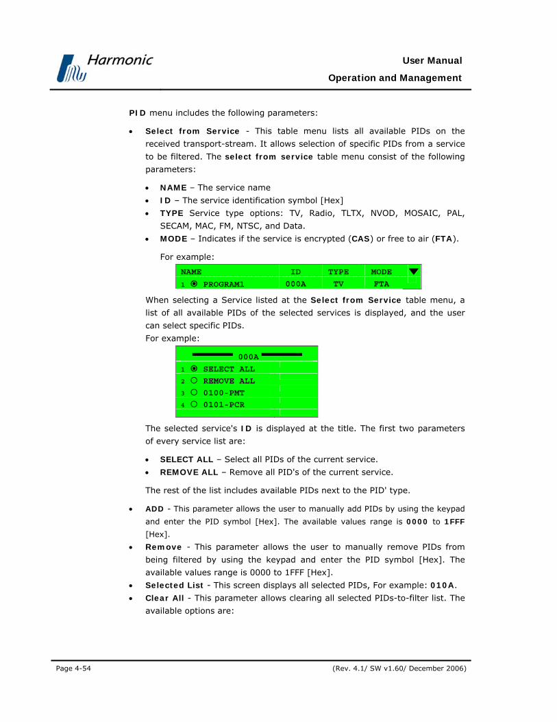
User Manual
Operation and Management
Page 4-54 (Rev. 4.1/ SW v1.60/ December 2006)
PID menu includes the following parameters:
• Select from Service - This table menu lists all available PIDs on the
received transport-stream. It allows selection of specific PIDs from a service
to be filtered. The select from service table menu consist of the following
parameters:
• NAME – The service name
• ID – The service identification symbol [Hex]
• TYPE Service type options: TV, Radio, TLTX, NVOD, MOSAIC, PAL,
SECAM, MAC, FM, NTSC, and Data.
• MODE – Indicates if the service is encrypted (CAS) or free to air (FTA).
For example:
NAME ID TYPE MODE
1 PROGRAM1 000A TV FTA
When selecting a Service listed at the Select from Service table menu, a
list of all available PIDs of the selected services is displayed, and the user
can select specific PIDs.
For example:
000A
1 SELECT ALL
2 REMOVE ALL
3 0100-PMT
4 0101-PCR
The selected service's ID is displayed at the title. The first two parameters
of every service list are:
• SELECT ALL – Select all PIDs of the current service.
• REMOVE ALL – Remove all PID's of the current service.
The rest of the list includes available PIDs next to the PID' type.
• ADD - This parameter allows the user to manually add PIDs by using the keypad
and enter the PID symbol [Hex]. The available values range is 0000 to 1FFF
[Hex].
• Remove - This parameter allows the user to manually remove PIDs from
being filtered by using the keypad and enter the PID symbol [Hex]. The
available values range is 0000 to 1FFF [Hex].
• Selected List - This screen displays all selected PIDs, For example: 010A.
• Clear All - This parameter allows clearing all selected PIDs-to-filter list. The
available options are:

PVR 6000 Series
Professional Integrated Receiver Decoders
Page 4-55
• OFF – clear list disabled.
• ON – active clear list.
NOTE
PID menu is applicable only when service filtering is selected from the Strategy
menu.
SELECT PIDS THRU THE WEB INTERFACE Select PIDs is the corresponding web-management screen that allows the user
to select PIDs in the filtering mode.
Figure 4-11 displays the corresponding Select PIDs configuration (Web
Management screen).
Figure 4-11: Select PIDs Menu Screen

User Manual
Operation and Management
Page 4-56 (Rev. 4.1/ SW v1.60/ December 2006)
Select PIDs screen includes following parameters:
• Const PIDs - This parameter lists all available SI PID's and allows the user
to select SI PIDs. In order to select SI PIDs, select the PIDs check boxes and
click Submit.
• Referenced PIDs - This parameter lists all available services PIDs on the
received transport-stream grouped under the relevant Service' nametag. It
allows selection of specific PIDs. In order to select a PID to filter, select the
needed PIDs' check boxes and click Submit.
• Unreferenced PIDs - This parameter lists all selected unreferenced PIDs. it
allows removal of an unreferenced PIDs. In order to remove an unreferenced
PID, select the PID' check box and click Submit.
NOTE
Unreferenced Services is unavailable when no unreferenced services have
been selected.
• Manual PID - This parameter allows the user to manually add PIDs by
entering the PIDs symbol in the text box and click on Submit.
NOTE
When the manually selected PID is a constant SI PID or it is part of a referenced
service, the relevant checkbox is checked; otherwise, the manually selected PID
is added under the unreferenced PIDs list
• Clear - Clicking on Clear button empty all selected fields.
NOTE
Service menu is applicable only when service filtering is selected from Strategy
menu

PVR 6000 Series
Professional Integrated Receiver Decoders
Page 4-57
4.2.5. Service Configuration Menu The Service Configuration Menu contains parameter setups for video and VBI
services.
Figure 4-12 displays a tree diagram of the Service Configuration Menu.
Figure 4-12: Service Configuration Menu
To access the Service Configuration Menu in the front panel control interface
go to Configuration Service.

User Manual
Operation and Management
Page 4-58 (Rev. 4.1/ SW v1.60/ December 2006)
The following screen displays the Service configuration menu:
Service 1-2-3
1 TV1 Select
2 TV2 Select
3 Stand-Alone Select
4 Preferred Language
5 PID Select
6 Mapping Port to Service
7 General Configuration+
The Service Configuration Menu parameters are as follows:
• TV1 and TV2 Select (if applicable)
Enables assign a service from the incoming TS to a decoder. In the case of a
dual decoder, a user can assign two services from the incoming TS, one for
each decoder (see Section 4.2.5.1).
• Stand-Alone
This feature will be supported in the future software releases.
• Preferred Language
This group contains parameters that define the preferred language (see
Section 4.2.5.3).
• PID Select
This group contains parameters that define the PID components in the
elementary stream (see Section 4.2.5.4).
• Mapping Port to Service
This group contains parameters that define the port mapping and service
components for each elementary stream (see Section 4.2.5.5).
• General Configuration
This group contains parameters that define the response of the PVR 6000 to
various operational modes (see Section 4.2.5.6).

PVR 6000 Series
Professional Integrated Receiver Decoders
Page 4-59
4.2.5.1. TV1 Select (and TV2 Select)
The TV1 Select (and TV2 Select in dual decoder IRDs screen lists the services
analyzed from the service descriptor contained in the SDT.
The services in the TV1 Select and TV2 Select Configuration are displayed as a
four-column table.
To access the TV1 Select (and TV2 Select) Table Menu in the front panel control
interface go to Configuration Service TV1 Select (or TV2 Select).
The following screen displays the TV1 Select (and TV2 Select) menu:
Name ID Type Mode
1 PROGRAM 1 000A TV FTA
2 PROGRAM 2 0046 TV FTA
3 PROGRAM 3 0050 TV CAS
4 PROGRAM 4 01F7 TV CAS
The table headers are as follows:
• NAME – The service name
• ID – The service identification symbol [Hex]
• TYPE Service type options: TV, Radio, TLTX, NVOD, MOSAIC, PAL, SECAM,
MAC, FM, NTSC, and Data.
• MODE – Indicates if the service is encrypted (CAS) or free to air (FTA)
Selecting a service from the TV1 and TV2 Table displays the following Service
Information table screen (relevant to the selected service):
TYPE PID Description Port
1 PCR 1262 PCR1
2 Video 1262 Video1
3 Audio 1273 English-eng AUDIO101
4 Vbi 1269 691.Swedish-swe VBI1

User Manual
Operation and Management
Page 4-60 (Rev. 4.1/ SW v1.60/ December 2006)
Figure 4-13displays the corresponding TV1 Menu (Web Management screen).
Figure 4-13: TV1 Menu Screen
The following paragraphs detail available types of elementary streams.
PCR The PCR elementary stream is a read only parameter.
VIDEO The following figure displays the TV1 Video screen:
Video
1 None
2 Video1
The following figure displays the TV2 Video screen:
Video
1 None
2 Video2

PVR 6000 Series
Professional Integrated Receiver Decoders
Page 4-61
The available options are:
• None – Video 1 (or Video 2 correspondingly) is not assigned to this Service.
• Video 1 (or Video 2) – Video 1 (or Video 2 correspondingly) is assigned to
the Service.
AUDIO The following figure displays the TV1 Audio screen:
Audio
1 None
2 Audio1
3 Audio2
The following figure displays the TV2 Audio screen:
Audio
1 None
2 Audio3
3 Audio4
The available options are:
• None – No Audio is assigned to this Service.
• Audio 1 (and Audio 3 correspondingly) – Audio 1 (or Audio 3
correspondingly) is assigned to the service.
• Audio 2 (and Audio 4 correspondingly) - Audio 2 (or Audio 4
correspondingly) is assigned to the service.
VBI The ProView™ PVR 6000 supports decoding and displaying Teletext Subtitling
graphics (according to DVB VBI standard EN 301 775, which specifies EBU
Teletext subtitling data, used for language translation).
Differently from DVB subtitling, Teletext Subtitling requires the decoder to be
able to create relevant language fonts. The PVR 6000 has the following Teletext
Subtitling fonts installed:
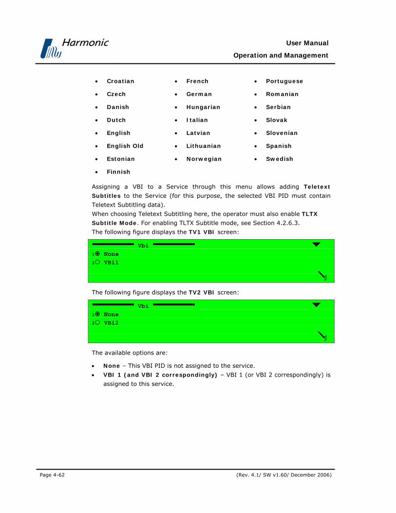
User Manual
Operation and Management
Page 4-62 (Rev. 4.1/ SW v1.60/ December 2006)
• Croatian
• Czech
• Danish
• Dutch
• English
• English Old
• Estonian
• Finnish
• French
• German
• Hungarian
• Italian
• Latvian
• Lithuanian
• Norwegian
• Portuguese
• Romanian
• Serbian
• Slovak
• Slovenian
• Spanish
• Swedish
Assigning a VBI to a Service through this menu allows adding Teletext
Subtitles to the Service (for this purpose, the selected VBI PID must contain
Teletext Subtitling data).
When choosing Teletext Subtitling here, the operator must also enable TLTX
Subtitle Mode. For enabling TLTX Subtitle mode, see Section 4.2.6.3.
The following figure displays the TV1 VBI screen:
Vbi
1 None
2 VBi1
The following figure displays the TV2 VBI screen:
Vbi
1 None
2 VBi2
The available options are:
• None – This VBI PID is not assigned to the service.
• VBI 1 (and VBI 2 correspondingly) – VBI 1 (or VBI 2 correspondingly) is
assigned to this service.

PVR 6000 Series
Professional Integrated Receiver Decoders
Page 4-63
4.2.5.2. Stand-Alone Select
This feature will be supported in the future software releases.
4.2.5.3. Preferred Language
The Preferred Language Edit menu screen lists the audio channels available
for the received services.
To access the Preferred Language Edit menu in the front panel control
interface go to Configuration Service Preferred Language.
Preferred Language 1-2-3-4
1 Audio 1 ALL LANGUAGES
2 Audio 2 English Old-ang
3 Audio 3 Romanian - ron
4 Audio 4 Zuylu - zul
05 VBi 1 1073
06 VBi 2 101F
07 Subtitling 1 1073
08 Subtitling 2 001F

User Manual
Operation and Management
Page 4-64 (Rev. 4.1/ SW v1.60/ December 2006)
Figure 4-14 displays the corresponding Preferred Language Menu (Web
Management screen).
Figure 4-14: Preferred Language Screen
NOTE
The number of audio channels provided in the Preferred Languages Menu is
dynamic and is determined by the PVR 6000 model. Audio 3 and Audio 4
channels are available in dual decoders, PVR 6040, and PVR 6050 models only.
The operator can assign a preferred language to each of the Audio channels, as
well as to the available VBIs and Subtitling.

PVR 6000 Series
Professional Integrated Receiver Decoders
Page 4-65
Selecting option displays a Select Value screen that lists the following available
languages:
01. ALL Languages
02. Albanian - alb
03. English Old - ang
04. Arabic - ara.
05. Armenian - arm.
06. Byelorussian - bel.
07. Bulgarian - bul.
08. Chechen - che
09. Chinese - chi
10. Check - cze
11. Danish - dan
12. German - deu
13. Dutch - dut
14. Egyptian - egy
15. English - eng
16. Spanish - esl
17. Finnish - fin
18. French - fra
19. French - fre
20. Gaelic - gae
21. German - ger
22. Greek Modern - gre
23. Hebrew - heb
24. Hindi - hin
25. Hungarian - hun
26. Indonesian - ind
27. Irish - iri
28. Italian - ita
29. Japanese - jpn
30. Latin - lat
31. Macedonian - mac
32. Miscellaneous - mis
33. Multiple - mul
34. Norvegian - nor
35. Turkish - ota
36. Persian - per
37. Polish - pol
38. Portuguese - por
39. Romany - rom
40. Romanian - ron
41. Russian - rus
42. Spanish - spa
43. Swedish - swe
44. Swedish - swe
45. Tamil -tam
46. Thai - tha
47. Zuylu - zul
NOTE
Option 01. ALL Languages (default).
No specific language is selected. The audio language is set according to the
Service PID.

User Manual
Operation and Management
Page 4-66 (Rev. 4.1/ SW v1.60/ December 2006)
4.2.5.4. PID Select
This option is intended for advanced users only and should not be used
normally.
Create a Service only through Configuration Service TV1/TV2 Select.
The PID Select menu allows the operator to directly assign an ES to an output
port directly, without attaching it to a Service. This option can be useful when
the PMT is not available or is defective.
Before assigning the ES to an output, the operator verifies that the new PID
entered is correct.
CAUTION
USING THIS CONTROL MENU DISASSOCIATES THE SELECTED ELEMENTRY STREAM FROM ANY
SERVICE AND MAKE IT A STAND ALONE STREAM WITH NO ATTATCH SYNCHRONIZATION AND NO
OTHER ASSOCIATED SIGNAL MAY COUSE VIDEO AND AUDIO ISSUES IF NOT HANDLES CORRECTLY. IT IS HIGHLY RECOMMENDED TO CONSULT HARMONIC INC. CUSTOMER SUPPORT BEFORE USING
THIS CONTROL MENU.
To access the PID Select Menu in the front panel control interface go to
Configuration Service PID Select.
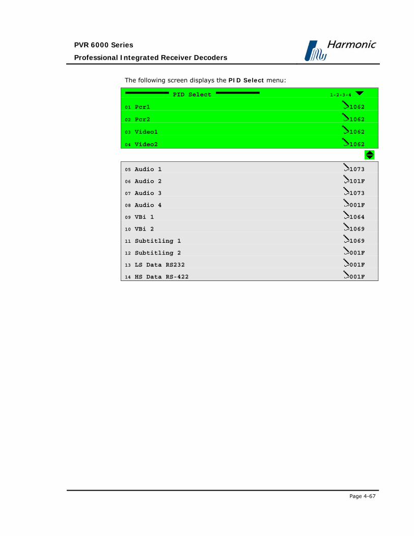
PVR 6000 Series
Professional Integrated Receiver Decoders
Page 4-67
The following screen displays the PID Select menu:
PID Select 1-2-3-4
01 Pcr1 1062
02 Pcr2 1062
03 Video1 1062
04 Video2 1062
05 Audio 1 1073
06 Audio 2 101F
07 Audio 3 1073
08 Audio 4 001F
09 VBi 1 1064
10 VBi 2 1069
11 Subtitling 1 1069
12 Subtitling 2 001F
13 LS Data RS232 001F
14 HS Data RS-422 001F

User Manual
Operation and Management
Page 4-68 (Rev. 4.1/ SW v1.60/ December 2006)
Figure 4-16 displays the corresponding PID Select Menu (Web Management
screen).
Figure 4-15: PID Select Menu Screen
The available options are:
• Pcr1
• Pcr2 (if applicable)
• Video1
• Video2 (if applicable)
• Audio1
• Audio2
• Audio3 (if applicable)
• Audio4 (if applicable)
• VBI1
• VBI2 (if applicable)
• Subtitling1
• Subtitling2 (if applicable)
• LS Data RS232
• HS Data RS-422
All PID-Assigning screens are identical in structure and functionality. The only
difference is the screen header, which changes according to the chosen port.

PVR 6000 Series
Professional Integrated Receiver Decoders
Page 4-69
The following figure is an example of a PID Assigning screen, as it appears in the
PVR 6000 front panel control interface (the selected port in this example is
Video1):
Video1
1062 [Hex]
<0000 - 1FFF>
Available values range from 0000 to 1FFF (Hexadecimal).
NOTES
The PVR 6000 decodes and displays DVB Subtitling according to the DVB-
Subtitling Standard ETS 300 743. This standard specifies the coding method of
subtitles, logos, and other graphical elements for the DVB and the method of
carrying them within a DVB Bit Stream.
Dual Decoder devices can decode two different programs, each with its own
subtitling simultaneously.
4.2.5.5. Mapping Port to Service
The Mapping Port to Service Menu enables the operator to manually map
PVR 6000 physical ports to Service 1 and to Service 2.
The factory default mapping (in dual decoders) is symmetrical. Service 1 is
assigned Video1, Audio1, Audio2, VBI1 etc. and Service 2 is assigned Video2,
Audio3, Audio4, VBI2, etc. Operator must not change these settings unless they
are well informed with PVR 6000 internal properties.
CAUTION
MAPPING PORT TO SERVICE IS INTENDED FOR ADVANCED USERS ONLY. CHANGING THIS OPTION’S
VALUES IS NOT RECOMMENDED. IN ALL CASES IT IS RECOMMENDED TO USE THE MAPPING PORT TO
SERVICE FACTORY DEFAULTS.
To access the Mapping Port to Service menu in the front panel control interface
go to Configuration Service Mapping Port to Service menu.

User Manual
Operation and Management
Page 4-70 (Rev. 4.1/ SW v1.60/ December 2006)
The following screen displays the Mapping Port to Service menu:
Mapping Port to Service 1-2-3-6
01 Pcr1 TV1
02 Pcr2 TV2
03 Video1 TV1
04 Video2 TV2
05 Audio 1 TV1
06 Audio 2 TV1
07 Audio 3 TV2
08 Audio 4 TV2
09 Vbi 1 TV1
10 Vbi 2 TV1
11 Subtitling 1 STAND ALONE
12 Subtitling 2 STAND ALONE
13 LS Data RS232 TV1
14 HS Data RS-422 STAND ALONE

PVR 6000 Series
Professional Integrated Receiver Decoders
Page 4-71
Figure 4-16 displays the corresponding Port to Service Menu (Web
Management screen).
Figure 4-16: Port to Service Menu Screen
The available options are:
• Pcr1 • Pcr2 (if applicable)
• Video1 • Video2 (if applicable)
• Audio1 • Audio2
• Audio3 (if applicable) • Audio4 (if applicable)
• VBI1 • VBI2 (if applicable)
• Subtitling1 • Subtitling2 (if applicable)
• LS Data RS232 • HS Data RS-422
• IP Data
MAPPING PORTS TO SERVICES THRU THE FRONT PANEL
In order to map a port to service thru the front panel, perform the following:
• Navigate to Configuration Service Mapping Port to Service

User Manual
Operation and Management
Page 4-72 (Rev. 4.1/ SW v1.60/ December 2006)
• Select one of the listed ports using the keypad. For example: PCR1.
After selection, the following menu screen lists all options for the selected
port.
PCR1
1 STAND ALONE
2 TV1
3 TV2
The available options are:
• STAND ALONE – This mode indicates that you can assign the
elementary stream PID. In this mode, the elementary stream is
independent of the services selected for Decoder#1 and decoder#2.
• TV1 – This mode indicates that the elementary stream is related to the
service assigned to Decoder#1.
• TV2 – This mode indicates that the elementary stream is related to the
service assigned to Decoder#2.
4.2.5.6. General Configuration
The Service General Configuration menu defines the PVR 6000 service
selection strategy (either automatic or user-defined). It also allows the operator
to instruct to the CAM (Conditional Access Module) which ES to decrypt.
To access the General Configuration menu, in the front panel control interface
go to Configuration Service General Configuration.
The following is the front panel General Configuration screen:
General Configuration 1-2-3-7
1 Service Strategy AUTO. Call 1st'….
2 Service CAS Open DECODED PID’S….

PVR 6000 Series
Professional Integrated Receiver Decoders
Page 4-73
Figure 4-17 displays the corresponding General Service menu (Web
Management screen).
Figure 4-17: General Service Menu Screen
The General Configuration Parameters are:
• Service Strategy
• Service CAS Open
SERVICE STRATEGY Service strategy determines the decoder' behaviour at the start-up or when
the decoding program is inactive. The following options in the Service Strategy
screen set the PVR 6000 service selection strategy parameters.
Service Strategy
1 AUTO. CALL 1st’ ACTIVE
2 WAIT FOR USER SELECT

User Manual
Operation and Management
Page 4-74 (Rev. 4.1/ SW v1.60/ December 2006)
The available options are:
• Auto. Call 1st Active – The PVR 6000 locks-onto the first active service
detected in the transport-stream. This mode is recommended for DSNG and
other applications that frequently change the decoded program.
NOTE
When Auto call first active mode is selected, the PVR 6000 might switch to the
first detected program when the TS is interrupted for any reason.
• Wait for User Select – The PVR 6000 searches for a specific (user-defined)
service to lock-on to the PVR 6000 is tuned to decode the selected program,
even if it does not exist in the TS. This mode is recommended for broadcast
applications where the decoded program is fixed, and seldom changes.
SERVICE CAS OPEN This parameter defines which ES will be decrypted by the CAM. It is possible to
either instruct the PVR 6000 to decrypt all the received ES, or allow it to decrypt
only the ones that are currently being decoded.
Service CAS Open
1 DECODED PID’S
2 ALL PMT PID’S
The available options are:
• DECODED PID’S – the CAM descrambles only the PIDs that are currently
decoded by the PVR 6000
• ALL PMT PID’S - the CAM descrambles all the received PIDs

PVR 6000 Series
Professional Integrated Receiver Decoders
Page 4-75
4.2.6. Video Configuration Menu The Video Configuration Menu contains parameters that set the video
decoder mode of operation.
Figure 4-18 displays a tree diagram of the Video Configuration Menu.
Figure 4-18: Video Configuration Menu
Video
Video 1 / Video 2 VBI 1 / VBI 2
Format
Lips-Sync Mode
CC
AMOL
STC-PCR Delay
VITS
VITC
WSS
TTX
VPS
SMC
Root
Preset Configuration Status
Interpolation
Monitor AspectRatio
Blanking Mode
OSD 1 / OSD 2
Monitor Output
Y Position Offset
DVB SubtitleMode
Broadcast Output
X Position Offset
TLTX SubtitleMode

User Manual
Operation and Management
Page 4-76 (Rev. 4.1/ SW v1.60/ December 2006)
NOTE
The number of Video Channel Configurations (as well as the VBI) provided in the
Video Configuration menu is dynamic and is determined by the PVR 6000 model.
To access the Video Configuration Menu in the front panel control interface go
to Configuration Video.
The following screen displays the Video menu:
Video 1-2-4
1 Video 1
2 VBI 1
3 Osd 1
4 Video 2
5 VBI 2
6 Osd 2
The Video Configuration parameters are as follows:
• Video 1
This group contains parameters that define the format, lip-sync mode and STC-PCR
delay parameters for the video stream for a signal to decoder #1.
For details on the Video 1 Parameter, see Section 4.2.6.1.
• VBI 1
This group contains parameters that define VBI functioning for Decoder #1.
For details on the VBI 1 Parameter, see Section 0.
• Osd 1
This group contains parameters that define OSD functioning for Decoder #1.
• Video 2 (if available)
This group contains parameters that define the format, lip-sync mode and STC-PCR
delay parameters for the video stream for a signal to decoder #2.
For details on the Video 2 Parameter, see Section 4.2.6.1.
• VBI 2 (if available)
This group contains parameters that define VBI functioning for the PVR 6000
Decoder #2.
For details on the VBI 2 Parameter, see Section 4.3.4.2.

PVR 6000 Series
Professional Integrated Receiver Decoders
Page 4-77
• Osd 2 (if available)
This group contains parameters that define OSD functioning for Decoder #2.
4.2.6.1. Video 1 and Video 2 Configuration Options
The Video 1 and Video 2 Menu allow the user to set parameters for Video 1
and/or Video 2 outputs (if applicable).
To access Video 1 or Video 2 menu screens navigate to Root Configuration
Video Video 1 or Video2
This section displays Video 1 configuration menu screens.
NOTE
Video 2 menu screens are identical to Video 1menu screens.
Video 1 1-2-4-1
1 Format PAL BG
2 Interpolation PAN-SCAN
3 Monitor Aspect-Ratio 4:3
4 Lip-sync Mode STANDARD LOCK
5 STC-PCR Delay 040 [mSec]
6 Blanking Mode Black
7 Test Mode NULL

User Manual
Operation and Management
Page 4-78 (Rev. 4.1/ SW v1.60/ December 2006)
Figure 4-19 displays the corresponding Video1 Menu (Web Management
screen).
Figure 4-19: Video 1 Menu Screen
The available options are:
• Format
• Interpolation
• Monitor Aspect-Ratio
• Lip-sync Mode
• STC-PCR Delay
• Blanking Mode
• Test Mode
NOTE
After selecting an option under the Video (1..2) menu, the front panel returns to
the Video (1..2) menu and displays the current selection.
The following paragraphs detail Video Configuration options.

PVR 6000 Series
Professional Integrated Receiver Decoders
Page 4-79
FORMAT The Format parameter selects the format of the video signal.
Format
1 NTSC (SETUP ON)
2 NTSC (SETUP OFF)
3 PAL M
4 PAL BG
5 PAL D
6 PAL N
7 SECAM
8 RUSSIAN SECAM
The available options are:
NTSC, PAL M, PAL BG, PAL D, PAL N, SECAM, RUSSIAN SECAM.
INTERPOLATION The Interpolation parameter sets the re-sampling method of the image (should
be set according to the Aspect Ratio parameter setting and to the actual aspect
ratio of the received video signal)
NOTE
See 04.3.8.4.Appendix C for extensive details on how Interpolation configuration
affects the resulting image.
Interpolation
1 PAN-SCAN
2 LETTER-BOX
3 PASS-THRU
The available options are:
• PAN-SCAN – Set interpolation to Pan & Scan
• LETTER-BOX – Set interpolation to Letter-Box
• PASS-THRU – No interpolation occurs.

User Manual
Operation and Management
Page 4-80 (Rev. 4.1/ SW v1.60/ December 2006)
MONITOR ASPECT-RATIO This parameter sets the intended image aspect ratio. It is used along with
Interpolation to determine the required Aspect Ratio Conversion.
NOTE
See 4.3.8.4.Appendix C for extensive details on how Monitor Aspect-Ratio
configuration affects the resulting image.
Monitor Aspect-Ratio
1 VIDEO Source
2 16:9
3 16:9 Box
4 4:3
5 14:9
6 14:9 Box
The available options are:
• VIDEO Source – Monitor aspect ratio is determined by the video sequence
• 16:9 – Monitor aspect ratio is set to 16:9.
• 16:9 Box – Monitor aspect ratio is set to 16:9 with letter-box.
• 4:3 – Monitor aspect ratio is set to 4:3.
• 14:9 – This option will be supported in future PVR 6000 versions.
• 14:9 Box – This option will be supported in future PVR 6000 versions.
NOTE
The option VIDEO Source should not be selected along with choosing TV
MONITOR under Configuration Video VBI 1 / 2 WSS, since the two A/R may
contradict each other and cause unexpected results.

PVR 6000 Series
Professional Integrated Receiver Decoders
Page 4-81
LIP-SYNC MODE The Lip-sync parameter selects the PVR 6000 lip-sync mode of operation.
Lip-sync Mode
1 STANDARD LOCK
2 2mSec LOCK (ONCE)
3 2mSec LOCK (NO DRIFT)
4 OFF
The available options are:
• STANDARD LOCK – Standard sync of video and audio data within ±40mSec
• 2mSec LOCK (ONCE) – Sync audio to video within ±2 mSec. In this mode,
the PVR 6000 synchronizes the audio to the video only once, monitoring
audio sync to video stops. Only PVR 6040 and PVR 6050 Audio 3 and Audio 4
support this feature.
• 2mSec LOCK (NO DRIFT) – Sync audio to video within ±2 mSec. In this
mode, the PVR 6000 continuously monitors the audio sync to video for
maintaining synchronization within ±2 mSec. Only PVR 6040 and PVR 6050
Audio 3 and Audio 4 support this feature.
• OFF – No Lip-Sync
STC-PCR DELAY The STC PCR Delay parameter sets the delay between the System Time Clock
(STC) and the PVR 6000 clock. The PVR 6000 clock is recovered from PCR data
to compensate for:
• Delay between STC and PCR
• Correctly processing the Presentation Time Setup (PTS)
• Preventing a buffer underflow
STC-PCR DELAY
040 [mSec]
<000 - 300>
Available delay range is a number from 0 to 300 mSec.
NOTE
In the Web management interface, set the STC PCR Delay by typing the
required delay (in Milliseconds) into the parameter’s free text window.

User Manual
Operation and Management
Page 4-82 (Rev. 4.1/ SW v1.60/ December 2006)
BLANKING MODE The Blanking Mode parameter sets the display mode of a service when
reception stops.
Blanking Mode
1 Black
2 Last Field
3 Last Frame
4 75% BAR
5 Null
The available options are:
• Black – video output signal is a black screen.
• Last Field – video output signal is the last field displayed.
• Last Frame – video output signal is the last frame displayed.
• 75% BAR – video output signal is a colour-bar display.
• Null – video outputs shut down with no output signal.
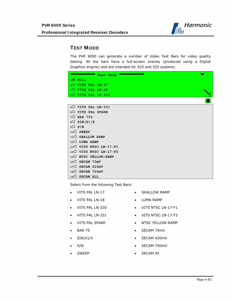
PVR 6000 Series
Professional Integrated Receiver Decoders
Page 4-83
TEST MODE The PVR 6000 can generate a number of Video Test Bars for video quality
testing. All the bars have a full-screen overlay (produced using a Digital
Graphics engine) and are intended for 625 and 525 systems.
Test Mode
1 NULL
2 VITS PAL LN-17
3 VITS PAL LN-18
4 VITS PAL LN-330
5 VITS PAL LN-331
6 VITS PAL SPARE
7 BAR 75%
8 SIN(X)/X
9 S/N
10 SWEEP
11 SHALLOW RAMP
12 LUMA RAMP
13 VITS NTSC LN-17-F1
14 VITS NTSC LN-17-F2
15 NTSC YELLOW-RAMP
16 SECAM 70mV
17 SECAM 420mV
18 SECAM 700mV
19 SECAM ALL
Select from the following Test Bars:
• VITS PAL LN-17 • SHALLOW RAMP
• VITS PAL LN-18 • LUMA RAMP
• VITS PAL LN-330 • VITS NTSC LN-17-F1
• VITS PAL LN-331 • VITS NTSC LN-17-F2
• VITS PAL SPARE • NTSC YELLOW-RAMP
• BAR 75 • SECAM 70mV
• SIN(X)/X • SECAM 420mV
• S/N • SECAM 700mV
• SWEEP • SECAM All
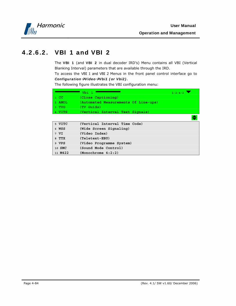
User Manual
Operation and Management
Page 4-84 (Rev. 4.1/ SW v1.60/ December 2006)
4.2.6.2. VBI 1 and VBI 2
The VBI 1 (and VBI 2 in dual decoder IRD’s) Menu contains all VBI (Vertical
Blanking Interval) parameters that are available through the IRD.
To access the VBI 1 and VBI 2 Menus in the front panel control interface go to
Configuration Video Vbi1 (or Vbi2).
The following figure illustrates the VBI configuration menu:
Vbi 1 1-2-4-2
1 CC (Close Captioning)
2 AMOL (Automated Measurements Of Line-ups)
3 TVG (TV Guide)
4 VITS (Vertical Interval Test Signals)
5 VITC (Vertical Interval Time Code)
6 WSS (Wide Screen Signaling)
7 VI (Video Index)
8 TTX (Teletext-EBU)
9 VPS (Video Programme System)
10 SMC (Sound Mode Control)
11 M422 (Monochrome 4:2:2)

PVR 6000 Series
Professional Integrated Receiver Decoders
Page 4-85
Figure 4-20 displays the corresponding VBI1 Web management screen.
Figure 4-20: VBI 1 Parameters
The following paragraphs describe the VBI Configuration options.
CC (CLOSED CAPTIONING) PARAMETER Selecting CC (Closed Captioning) displays the following screen:
CC 1-2-4-2-1
1 Source DISABLE
2 Line1 21
The CC screen parameters are:
1 Source – used for selecting the source of closed captioning data
2 Line1 – This is a read-only parameter (closed captioning data is
automatically re-inserted in line 21).
Selecting Source displays the following screen:

User Manual
Operation and Management
Page 4-86 (Rev. 4.1/ SW v1.60/ December 2006)
Source
1 DISABLE
2 E.S (EN-301-775)
3 VIDEO
4 VIDEO (ATSC A/53)
Available Closed Captioning sources are:
• DISABLE – CC is disabled.
• E.S (EN-301-775) – CC data is acquired according to the EN 301-775 DVB
standard.
• VIDEO – The PVR 6000 automatically detects the existing CC standard and
acquires the CC data accordingly.
• VIDEO (ATSC A/53) – The PVR 6000 automatically detects the existing CC
standard and acquires the CC data accordingly, prioritizing the ATSC A/53
standard.
NOTE
The PVR 6000 supports the following CC standards:
CCube standard
Harmonic Divicom standard
ATSC DVS-53 (Rev 57) EIA 608
ATSC DVS-53 (Rev 57) caption type 4
GI DVS-157
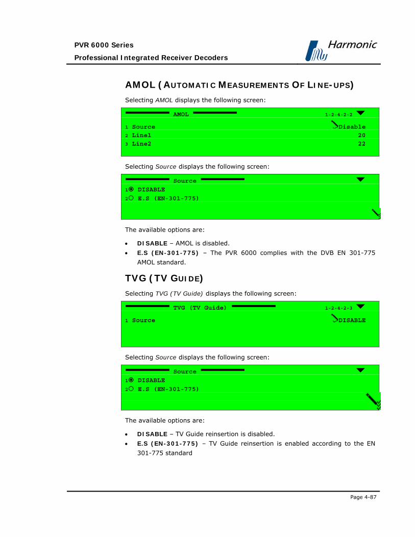
PVR 6000 Series
Professional Integrated Receiver Decoders
Page 4-87
AMOL (AUTOMATIC MEASUREMENTS OF LINE-UPS) Selecting AMOL displays the following screen:
AMOL 1-2-4-2-2
1 Source Disable
2 Line1 20
3 Line2 22
Selecting Source displays the following screen:
Source
1 DISABLE
2 E.S (EN-301-775)
The available options are:
• DISABLE – AMOL is disabled.
• E.S (EN-301-775) – The PVR 6000 complies with the DVB EN 301-775
AMOL standard.
TVG (TV GUIDE) Selecting TVG (TV Guide) displays the following screen:
TVG (TV Guide) 1-2-4-2-3
1 Source DISABLE
Selecting Source displays the following screen:
Source
1 DISABLE
2 E.S (EN-301-775)
The available options are:
• DISABLE – TV Guide reinsertion is disabled.
• E.S (EN-301-775) – TV Guide reinsertion is enabled according to the EN
301-775 standard

User Manual
Operation and Management
Page 4-88 (Rev. 4.1/ SW v1.60/ December 2006)
VITS (VERTICAL INTERVAL TEST SIGNALS) PARAMETER The PVR 6000 supports 10 different VITS signals: 4 signals for PAL, 2 signals for
NTSC and 4 signals for SECAM and Russian SECAM. The VITS signals are
automatically selected according to the selected video format (PAL, TSC or
SECAM/R.SECAM). The PAL and NTSC VITS signals are according to ITU-T J.63 standard:
• PAL- Lines 17, 18, 330, 331 • NTSC- Line 17 Field 1, Line 17 Field 2 • SECAM/R.SECAM- Lines 17, 18, 330, 331
When working in PAL or SECAM/R.SECAM video format, the user can select two
lines. The factory setting is to Line 1: 17 and Line 2: 18. In this case, the PVR
6000 will re-insert the VITS signals automatically to lines 17, 18, 330, 331. In
the case of selecting different line numbers for VITS, the PVR 6000 calculates
the new line numbers in which to re-insert the VITS signals. For example,
changing Line 2 to 19 (instead of 18) will result in VITS signals re-inserted to
lines: 17, 19, 330 and 332. When the VBI Vertical Interval Test Signals (VITS) parameter is selected,
the following screen is displayed:
VITS 1-2-4-2-4
1 Source INTERNAL
2 Line1 17
3 Line2 18
Selecting Source displays the following screen:
Source
1 DISABLE
2 INTERNAL
The available options are:
• DISABLE – VITS is disabled.
• INTERNAL – The PVR 6000 inserts the VITS signal according to the ITU-T
standard J. 63.

PVR 6000 Series
Professional Integrated Receiver Decoders
Page 4-89
When selecting the Line 1 option, the following screen is displayed:
Line1
17
<00 - 23>
When selecting the Line 2 option, the following screen is displayed:
Line2
18
<00 - 23>
The VITS signal is inserted differently if using PAL or NTSC. When selecting PAL,
VITS signals are inserted to lines 17 and 18 and to lines 330 and 331. When
selecting NTSC, VITS signals are inserted to line 17-field 1 and line 17-field 2.
The PVR 6000 enables the user to insert VITS signals to lines 17 and 18 as well
as to any other line between 0 and 23.
NOTE
In Russian SECAM format, there are special VITS signals, different in format
from PAL VITS. The Russian SECAM VITS are inserted in lines 17 and 18 and in
lines 330, and 331.
Only the PVR 6000, PVR 6010, and PVR 6060 support special Russian SECAM
VITS.

User Manual
Operation and Management
Page 4-90 (Rev. 4.1/ SW v1.60/ December 2006)
VITC (VERTICAL INTERVAL TIME CODE) PARAMETER When the Vertical Interval Time Code (VITC) VBI parameter is selected, the
following screen is displayed:
VITC 1-2-4-2-5
1 Source DISABLE
2 Line1 12
3 Line2 14
Selecting Source displays the following screen:
Source
1 DISABLE
2 INTERNAL
3 VIDEO
The available options are:
• DISABLE – VITC is disabled.
• INTERNAL – The PVR 6000 re-inserts the PVR 6000 uptime.
• VIDEO – The PVR 6000 re-inserts the VITC signal as included in the
transport stream.
When selecting the Line 1 option, the following screen is displayed:
Line1
12
<00 - 23>
When selecting the Line 2 option, the following screen is displayed:
Line2
14
<00 - 23>
The PVR 6000 allows inserting VITC to any line between 0 and 23.

PVR 6000 Series
Professional Integrated Receiver Decoders
Page 4-91
WSS (WIDE-SCREEN SIGNALLING) PARAMETER Selecting Wide-Screen Signaling (WSS) displays the following screen:
WSS 1-2-4-2-6
1 Source E.S (EN-301-775)
2 Line1 23
Selecting Source displays the following screen:
Source
1 DISABLE
2 TV MONITOR
3 E.S (EN-301-775)
4 VIDEO
The available options are:
• DISABLE – The PVR 6000 does not output a WSS signal.
• TV MONITOR – The PVR 6000 generates the WSS signal according to the
Aspect Ratio value entered by the operator through
Root Configuration Video (1..2) Monitor Aspect-Ratio (complies with ITU-
T standard J. 63).
NOTE
The option TV MONITOR should not be selected along with choosing VIDEO
Source under Configuration Video Video 1 / 2 Monitor Aspect Ratio,
since the two A/R may contradict each other and cause unexpected results.
• E.S. (EN-301-775) – The PVR 6000 generates the WSS signal according to
the WSS information taken from the VBI Elementary Stream (complies with
DVB EN 301-775 WSS standard).
• VIDEO – The PVR 6000 generates the WSS signal according to the WSS
information taken from the Video Header in the Video Elementary Stream.
NOTE
See 4.3.8.4.Appendix C for extensive details on how WSS configuration affects the
resulting image.

User Manual
Operation and Management
Page 4-92 (Rev. 4.1/ SW v1.60/ December 2006)
Selecting Line1 displays the following screen:
Line1
23
<00 - 23>
The WSS signal can be inserted into a line between 0 and 23.
VI (VIDEO INDEX) The PVR 6000 supports AFD (Active Video Format Description) parsing, when
such data exists in the video e.s. – User Data, according to ETSI TS 101 154
Annex B. The AFD data is reinserted into VBI VI (Video Indexing) line 11, on 625
systems, according to SMPTE RP 186-1995 (only Class 1.1 “Information required
to display the signal, not including pan and scan” is currently supported).
Selecting VI (Video Index) displays the following screen:
VI (Video Index) 1-2-4-2-7
1 Source VIDEO
2 Line1 11
Selecting Source displays the following screen:
Source
1 DISABLE
2 E.S (EN-301-775)
3 VIDEO
The available options are:
• DISABLE – VI data is not reinserted.
• E.S.(EN-301-775) – will be supported in the future software releases
• VIDEO – the PVR 6000 automatically detects the existing standard and
reinserts the VI data accordingly.
Line1 is a read-only parameter. VI data is always reinserted into line 11.

PVR 6000 Series
Professional Integrated Receiver Decoders
Page 4-93
TTX (TELETEXT-EBU) PARAMETER When the TTX (Teletext-EBU) VBI parameter is selected, the following screen
is displayed:
TTX (Teletext EBU) 1-2-4-2-8
1 Source DISABLE
Selecting Source displays the following screen:
Source
1 DISABLE
2 E.S (EN-301-775)
The available options are:
• DISABLE – Teletext is disabled.
• E.S (EN-301-775) – The PVR 6000 re-inserts the Teletext signal as
included in the transport stream according to EN 301-775.
VPS (VIDEO PROGRAM SYSTEM) PARAMETER When the VPS (Video Program System) VBI parameter is selected, the
following screen is displayed:
VPS 1-2-4-2-9
1 Source DISABLE
2 Line1 16
Selecting Source displays the following screen:
Source
1 DISABLE
2 E.S (EN-301-775)
The available options are:
• DISABLE – VPS is disabled.

User Manual
Operation and Management
Page 4-94 (Rev. 4.1/ SW v1.60/ December 2006)
• E.S (EN-301-775) – The PVR 6000 re-inserts the signal as included in the
transport stream in accordance with EN 301-775.
SMC (VIDEO PROGRAM SYSTEM) This feature will be supported in the future software releases.
M422 (MONOCHROME 4:2:2) Selecting M422 (Monochrome 4:2:2) displays the following screen:
M422 (Monochrome 4:2:2) 1-2-4-2-11
1 Source E.S (EN-301-775)
Selecting Source displays the following screen:
Source
1 DISABLE
2 E.S (EN-301-775)
The available options are:
• DISABLE – Monochrome 4:2:2 reinsertion is disabled
• E.S (EN-301-775) – Monochrome 4:2:2 reinsertion is enabled according to
the EN 301-775 standard.

PVR 6000 Series
Professional Integrated Receiver Decoders
Page 4-95
4.2.6.3. OSD 1 and OSD 2
The OSD 1 and OSD 2 Menu contains parameters for Video 1 and Video 2 (if
applicable).
These menus are entered from the PVR 6000 Video Configuration Menu (see
Section 4.2.6). The following screens display the Video 1 and Video 2 menus:
Osd 1 1-2-4-1
1 Monitor Output ENABLE
2 Broadcast Output ENABLE
3 X Position Offset 000 [Pixel]
4 Y Position Offset 000 [Pixel]
5 DVB Subtitle Mode NO PAGE FILTER
6 TLTX Subtitle Mode DISABLE
Figure 4-21 displays the corresponding OSD1 Menu (Web Management screen).
Figure 4-21: OSD1 Menu Screen

User Manual
Operation and Management
Page 4-96 (Rev. 4.1/ SW v1.60/ December 2006)
The available options are:
• Monitor Output
• Broadcast Output
• X Position Offset
• Y Position Offset
• DVB Subtitle Mode
• TLTX Subtitle Mode
The following paragraphs describe the OSD 1 and OSD 2 parameters:
MONITOR OUTPUT Selecting Monitor Output displays the following screen:
Monitor Output
1 DISABLE
2 ENABLE
The available options are:
• DISABLE – Disables Monitor Output (PVR 6000 rear panel)
• ENABLE – Enables Monitor Output
BROADCAST OUTPUT
Selecting Broadcast Output displays the following screen:
Broadcast Output
1 DISABLE
2 ENABLE
The available options are:
• DISABLE – Disables Broadcast Output (PVR 6000 rear panel)
• ENABLE – Enables Broadcast Output

PVR 6000 Series
Professional Integrated Receiver Decoders
Page 4-97
X POSITION OFFSET Selecting X Position Offset displays the following screen:
X Position Offset
+000 [Pixel]
<-300 - +300>
This function determines the horizontal offset of the OSD signal.
The valid range of values is between (-300) and (+300) pixels
Y POSITION OFFSET Selecting Y Position Offset displays the following screen:
Y Position Offset
+000 [Pixel]
<-300 - +300>
This function determines the vertical offset of the OSD signal.
The valid range of values is between (-300) and (+300) pixels
DVB SUBTITLE MODE Selecting DVB Subtitle Mode displays the following screen:
DVB Subtitle Mode
1 DISABLE
2 NO PAGE FILTER
3 USE PAGE FILTER
The available options are:
• DISABLE – Disables DVB Subtitling.
• NO PAGE FILTER – This is the PVR 6000 default setting.
• USE PAGE FILTER – Use this option when more than one DVB subtitling
pages exist in the OSD PID. The Page Filter identifies the page that contains
actual subtitling data.

User Manual
Operation and Management
Page 4-98 (Rev. 4.1/ SW v1.60/ December 2006)
TLTX SUBTITLE MODE Different from DVB subtitling, Teletext Subtitling requires the decoder to create
relevant language fonts. The PVR 6000 has the following Teletext Subtitling
fonts installed (all fonts according to ETS 300 706):
• Croatian
• Czech
• Danish
• Dutch
• English
• English Old
• Estonian
• Finnish
• French
• German
• Hungarian
• Italian
• Latvian
• Lithuanian
• Norwegian
• Portuguese
• Romanian
• Serbian
• Slovak
• Slovenian
• Spanish
• Swedish
Selecting TLTX Subtitle Mode displays the following screen:
TLTX Subtitle Mode
1 DISABLE
2 ENABLE
The available options are:
• DISABLE – Disables Teletext Subtitling
• ENABLE – Enables Teletext Subtitling
NOTE
When selecting DVB Subtitle Mode, TLTX Subtitle Mode is automatically
disabled, and vice versa, since only one set of subtitling is allowed per program.

PVR 6000 Series
Professional Integrated Receiver Decoders
Page 4-99
4.2.7. Audio Configuration Menu The Audio Configuration Menu contains parameters that define the audio
decoder mode of operation.
Figure 4-22 displays a tree diagram of the Audio Configuration Menu.
Figure 4-22: Audio Configuration Menu
NOTE
The number of Audio Channel Configurations provided in the Audio Configuration
menu is dynamic and is set by the unit configuration.
Audio
Audio #
PassThruSample Rate
Volume
AnalogOutput
Analog Mixer
Digital Format
DecoderMode
AC3 DownmixMode
AC3Operational
Root
Preset Configuration Status

User Manual
Operation and Management
Page 4-100 (Rev. 4.1/ SW v1.60/ December 2006)
To access the Audio Configuration Menu, in the front panel control interface
go to Configuration Audio.
The following screen displays the Audio Configuration Menu:
Audio 1-2-5
1 Audio 1
2 Audio 2
3 Audio 3
4 Audio 4
The available options are:
• Audio 1
• Audio 2
• Audio 3 (in dual decoder IRDs)
• Audio 4 (in dual decoder IRDs)
Audios 1 through 4 have identical parameters, and are accessible through
identical controls. The following is an example of Audio 1 front panel control
screen. Audio 2, 3, and 4 control screens are exactly the same (except for the
screen header).
NOTE
Audio1 and Audio2 correspond with Video1 and are always available. Audio3
and Audio4 correspond with Video2 and are available only in dual decoder
IRDs.

PVR 6000 Series
Professional Integrated Receiver Decoders
Page 4-101
4.2.7.1. Audio 1
To access the Audio 1 Menu in the front panel control interface go to
Configuration Audio Audio1.
The following screen displays the Audio 1 menu:
Audio1(1..2) 1-2-5-1
1 Decoder Mode MUSICAM
2 AC3 Downmix Mode 2/0 L,R STEREO
3 AC3 Operational LINE OUT MODE
4 PassThru Sample Rate 48.0 [KHz]
5 Volume 00.0 [Db]
6 Analog Output UNMUTE (PLAY)
7 Analog Mixer STEREO (L & R)
8 Digital Format Professional
8 Test Tone DISABLE

User Manual
Operation and Management
Page 4-102 (Rev. 4.1/ SW v1.60/ December 2006)
Figure 4-23 displays the corresponding Audio1 Menu (Web Management
screen).
Figure 4-23: Audio 1 Menu Screen
The available options are:
• Decoder Mode
• AC3 Downmix Mode
• AC3 Operational
• PassThru Sample Rate
• Volume
• Analog Output
• Analog Mixer
• Digital Format
• Test Tone

PVR 6000 Series
Professional Integrated Receiver Decoders
Page 4-103
NOTES
Although AC3 Downmix Mode, AC3 Operational Mode, and PassThru Sample Rate
parameters can always be accessed from the Audio (1..4) Parameters window, they are affective
only when their corresponding mode is selected in Decoder Mode.
In the Web Management window, AC3 Downmix Mode and AC3 Operational Mode are effective
only when Dolby AC3 is selected in Decoder Mode
In the Web Management, window PassThru Sample Rate is effective only when PassThru is
selected in Decoder Mode.
Digital Format will be supported by the PVR 6000 Web Control interface in the future SW releases.
The following paragraphs detail the Audio Configuration options.
AUDIO DECODER MODE SETUP The Audio Decoder mode option allows the user setting the following
parameters for an Audio channel:
Decoder Mode
1 MUSICAM
2 DOLBY-AC3
3 AC3 PASSTHRU
4 LINEAR-PCM
5 AUTOMATIC
This menu controls the decoder audio mode; The available options are:
• MUSICAM – Sets the audio decoder mode to MUSICAM
• DOLBY-AC3 – Sets the audio decoder mode for the AC-3 downmix
• AC3 PASSTHRU – Sets the audio decoder mode to AC-3 Pass-through
• LINEAR-PCM – Sets the audio decoder mode to Linear PCM and Dolby E
Pass-through. Only PVR 6040 , PVR 6050, PVR 6070 , and PVR 6070 Audio
3 and Audio 4 support this feature
• AUTOMATIC – Automatically detects the audio decoding mode
NOTE
Audio3 and Audio 4 Decoder Mode parameters must be identical .For example:
when Audio3 Decoder mode is set to AC3 PASSTHRU, Audio 4 must be set to
AC3 PASSTHRU as well.

User Manual
Operation and Management
Page 4-104 (Rev. 4.1/ SW v1.60/ December 2006)
AC3 DOWNMIX MODE SETUP The AC-3 Downmix mode allows you to set the downmix mode to 2/0.
AC3 Downmix Mode
1 2/0 L,R
2 1/0 C MONO
3 2/0 L,R STEREO
4 3/0 L,C,R
5 2/1 L,R,S
6 3/1 L,C,R,S
7 2/2 L,R,Ls,Rs
8 2/2 L,C,R,Ls,Rs
The available options are:
• 2/0 L, R
• 2/0 C mono
• 2/0 L, R stereo
• 3/0 L, C, R
• 2/1 L, R, S
• 3/1 L, C, R, S
• 2/2 L, R, Ls, Rs
• 2/2 L, C, R, Ls, Rs
AUDIO AC3 OPERATIONAL SETUP The Audio AC3 Operational parameter selects the audio output mode of
operation on a specific audio for the Dolby AC-3 processed audio information
(for example, Audio 1 output).
AC3 Operational
1 CUSTOM MODE 0
2 CUSTOM MODE 1
3 LINE OUT MODE
4 RF REMOD MODE
The available options are:
• Custom Mode 0
• Custom Mode 1
• Line Out Mode
• RF Remod Mode

PVR 6000 Series
Professional Integrated Receiver Decoders
Page 4-105
NOTE
The default for Audio AC-3 Operational output is Line Out mode.
PASSTHRU SAMPLE RATE The PassThru Sample Rate parameter allows the user setting the sampling
frequency for the AC3 Pass-through.
PassThru Sample Rate
1 48.0 [KHz]
2 44.1 [KHz]
3 32.0 [KHz]
The available options are:
• 48.0 [KHz]
• 44.1 [KHz]
• 32.0 [KHz]
VOLUME The Volume parameter allows the user setting the audio volume of the audio
channel.
A graphical volume display illustrates the volume level.
Volume
00 [dB]
< -64 - 00 >
Available values are between (–)64 and 0dB.
ANALOG OUTPUT The Analog Output parameter sets Mute or Play mode in an audio channel
output.
Analog Output
1 MUTE
2 UNMUTE (PLAY)

User Manual
Operation and Management
Page 4-106 (Rev. 4.1/ SW v1.60/ December 2006)
The available options are:
• MUTE – this analog audio output is disabled
• UNMUTE (PLAY) – this analog audio output is enabled
ANALOG MIXER The Analog Mixer parameter, displayed on the following screen, allows setting
the stereo and mono options of the stereo channels.
Analog Mixer
1 STEREO(L & R)
2 MONO MIXING
3 SWAP (R & L)
4 BOTH RIGHT
5 BOTH LEFT
The available options are:
• STEREO (L & R) – Standard stereo output on the respective left and right
connectors
• MONO MIXING – Mixes left and right stereo channel signals for mono
output on both left and right connectors
• SWAP (R & L) – Swaps channels:
• Left channel on right connectors
• Right channel on left connectors
• BOTH RIGHT – Outputs right channels on both left and right connectors
• BOTH LEFT – Outputs left channels on both left and right connectors
NOTES
Audio 2 Parameters menu is identical in its form and functionality to the Audio 1 Parameters menu (see Error! Reference source not found.).
Recall that Audio 3 and Audio 4 menus correspond with Video2, and are also
identical in form and functionality to Audio 1 and Audio 2.

PVR 6000 Series
Professional Integrated Receiver Decoders
Page 4-107
DIGITAL FORMAT The Digital Format parameter sets the digital audio channel output mode.
Digital Format
1 CONSUMER
2 PROFESSIONAL
The available options are:
• CONSUMER – Selects AES/EBU, SPDIF Consumer Mode. – This mode
passes the audio mode bits as is.
• PROFESSIONAL – Selects AES/EBU Professional Mode. This mode set the audio mode to stereo regardless of actual audio.
NOTE
When Consumer mode is chosen: the IRD passes the audio mode bits as is.
When Professional mode is chosen: the IRD sets the audio mode to stereo
regardless of actual audio.
NOTE
When choosing PROFESSIONAL, the PVR 6000 will set the Audio header’s Pro
flag to 1 (‘Pro’) whether the received value was 1 or 0.
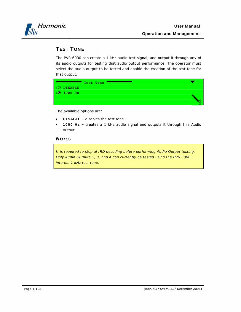
User Manual
Operation and Management
Page 4-108 (Rev. 4.1/ SW v1.60/ December 2006)
TEST TONE The PVR 6000 can create a 1 kHz audio test signal, and output it through any of
its audio outputs for testing that audio output performance. The operator must
select the audio output to be tested and enable the creation of the test tone for
that output.
Test Tone
1 DISABLE
2 1000 Hz
The available options are:
• DISABLE – disables the test tone
• 1000 Hz – creates a 1 kHz audio signal and outputs it through this Audio
output
NOTES
It is required to stop al IRD decoding before performing Audio Output testing.
Only Audio Outputs 1, 3, and 4 can currently be tested using the PVR 6000
internal 1 kHz test tone.

PVR 6000 Series
Professional Integrated Receiver Decoders
Page 4-109
4.2.8. Data Configuration Menu The Data Configuration Menu allows setting parameters to handle a data
output stream.
Figure 4-24 displays a tree diagram of the Data Configuration Menu.
Figure 4-24: Data Configuration Menu
OperationalMode
DefaultGateway
Dest IPAddress
UDP SourcePort
UDPDestination Port
Num OfPackets
Protocol
IP Address
Subnet Mask
Root
Preset Configuration Status
Low SpeedData Port IP Out Port

User Manual
Operation and Management
Page 4-110 (Rev. 4.1/ SW v1.60/ December 2006)
To access the Data Configuration Menu in the front panel control interface go to
Configuration Data.
All the PVR 6000 models except PVR 6000 and PVR 6060 support the IP-Out-
Port option. Following is the corresponding front-panel screen:
Data 1-2-6
1 Low Speed Data Port 2 IP Out Port
The PVR 6000 and PVR 6060 models support the High Speed Data Port option
(and not IP Out Port). Following is the corresponding front-panel screen for
these models:
Data 1-2-6
1 Low Speed Data Port
2 High Speed Data Port
The Data Configuration Menu parameters are:
• Low Speed Data Port
Sets the type of data to be outputted through the Low Speed Data port. The PVR
6000 supports LS data output in three levels of filtering. For details see Section
4.2.8.1.
• IP Out Port
Sets the PVR 6000 IP Out port parameters (e.g. the chosen transfer protocol, the
PVR 6000 IP address, UDP port and so on.). For detailed information, see Section
4.2.8.2.
• High Speed Data Port (PVR 6000 and PVR 6060 only)
Sets the transfer rate & direction, and the type of data to be sent, through the
High Speed Data port. For details see Section 4.2.8.3.

PVR 6000 Series
Professional Integrated Receiver Decoders
Page 4-111
4.2.8.1. Low Speed Data Port
This menu is used for setting the PVR 6000 Low Speed Data port parameters.
The PVR 6000 supports Low Speed Data output through RS232. It enables
different rates of transmission, as well as three levels of output-data filtering.
NOTE
The PVR 6000 automatically directs PIDs with the MPEG-2 descriptor -
private_data_indicator = 15 with indicator value 0 for transmission through its
Low Speed Data port.
The minimum amount of data that can be transmitted through the LS Data port
is the size of one PES payload.
To access the Low Speed Data menu, in the front panel control interface go to
Configuration Data Low Speed Data Port
Following is the corresponding front-panel screen:
Low Speed Data Port 1-2-6-1
1 Baud Rate 115200 [Baud]
2 Layer Filtering P.E.S Payload
The Low Speed Date Port screen contains the following parameters:
• Baud Rate
• Layer Filtering
The following paragraphs provide details of these parameters.

User Manual
Operation and Management
Page 4-112 (Rev. 4.1/ SW v1.60/ December 2006)
BAUD RATE This parameter enables electing between eight possible LS data transmission
rates. Following is the corresponding front panel screen:
Baud Rate
1 1200 [Baud]
2 2400 [Baud]
3 4800 [Baud]
4 9600 [Baud]
5 19200 [Baud]
6 38400 [Baud]
7 57600 [Baud]
8 115200 [Baud]
The available transmission rates are: 1200, 2400, 4800, 9600, 19200, 38400,
57600, and 115200 Baud.
NOTE
The LS Data transmission Baud Rate settings must comply with the
corresponding encoder data-encapsulation rate.
LAYER FILTERING The PVR 6000 supports three levels of Low Speed Data filtering, determining the
type of data to be transmitted through the LS Data port. Following is the front
panel Layer Filtering screen:
Layer Filtering
1 DVB STREAMING
2 PES PAYLOAD
3 T.S PAYLOAD
The three levels of data filtering are:
• DVB STREAMING – For outputting only DVB Asynchronous Data Streaming
according to the EN-301-192 standard (the first 3 bytes of the
PES_data_packet are stripped)
• PES PAYLOAD – For outputting only the PES payload (the PES header is
stripped)
• T.S PAYLOAD or outputting only the transport stream payload (the TS
header and the adaptation field are stripped)
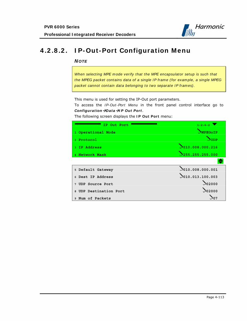
PVR 6000 Series
Professional Integrated Receiver Decoders
Page 4-113
4.2.8.2. IP-Out-Port Configuration Menu
NOTE
When selecting MPE mode verify that the MPE encapsulator setup is such that
the MPEG packet contains data of a single IP frame (for example, a single MPEG
packet cannot contain data belonging to two separate IP frames).
This menu is used for setting the IP-Out port parameters.
To access the IP-Out-Port Menu in the front panel control interface go to
Configuration Data IP Out Port.
The following screen displays the IP Out Port menu:
IP Out Port 1-2-6-2
1 Operational Mode MPEGoIP
2 Protocol UDP
3 IP Address 010.008.000.216
4 Network Mask 255.255.255.000
5 Default Gateway 010.008.000.001
6 Dest IP Address 010.013.100.003
7 UDP Source Port 02000
8 UDP Destination Port 02000
9 Num of Packets 07

User Manual
Operation and Management
Page 4-114 (Rev. 4.1/ SW v1.60/ December 2006)
Figure 4-23 displays the corresponding IP DATA PORT Menu (Web
Management screen).
Figure 4-25: IP DATA PORT Menu Screen
The available options are:
• Operational Mode
• Protocol
• IP Address
• Network Mask
• Default Gateway
• Dest IP Address
• UDP Source Port
• UDP Destination Port
• Num of Packets

PVR 6000 Series
Professional Integrated Receiver Decoders
Page 4-115
OPERATIONAL MODE The Operational Mode screen displays the currently active mode of operation
and allows setting the mode using the following Select Value screen:
Operational Mode
1 MPEGoIp
2 MPE
The available options are:
• MPEGoIp – MPEG-over-IP mode
• MPE – IP data (MPE de-capsulation)
NOTE
When Operational mode is set to MPEG-over-IP, all other items in the IP-Out-
Port menu must be configured. When Operational mode is set to MPE, then the
IP address, Subnet Mask, and Default Gateway items must be configured.
PROTOCOL The Protocol screen displays the currently active L3 protocol and allows setting
the protocol using the following Select Value screen.
Protocol
1 UDP
2 RTP
The available options are:
• UDP – User Datagram Protocol
• RTP – Real Time Protocol (this feature will be supported in future software
releases)
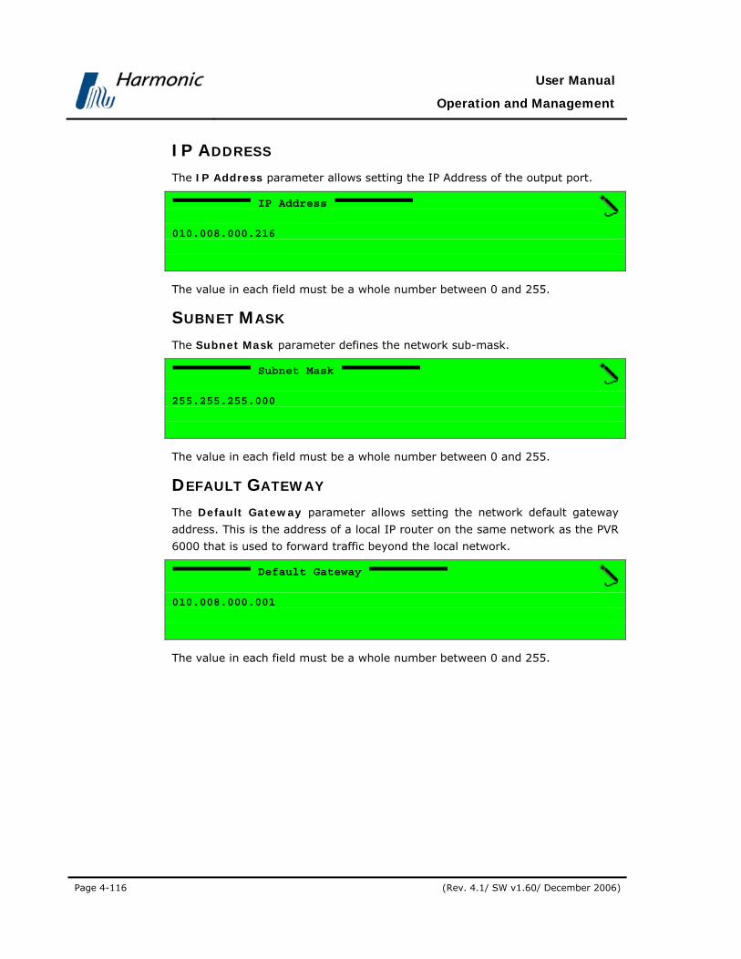
User Manual
Operation and Management
Page 4-116 (Rev. 4.1/ SW v1.60/ December 2006)
IP ADDRESS The IP Address parameter allows setting the IP Address of the output port.
IP Address
010.008.000.216
The value in each field must be a whole number between 0 and 255.
SUBNET MASK The Subnet Mask parameter defines the network sub-mask.
Subnet Mask
255.255.255.000
The value in each field must be a whole number between 0 and 255.
DEFAULT GATEWAY The Default Gateway parameter allows setting the network default gateway
address. This is the address of a local IP router on the same network as the PVR
6000 that is used to forward traffic beyond the local network.
Default Gateway
010.008.000.001
The value in each field must be a whole number between 0 and 255.
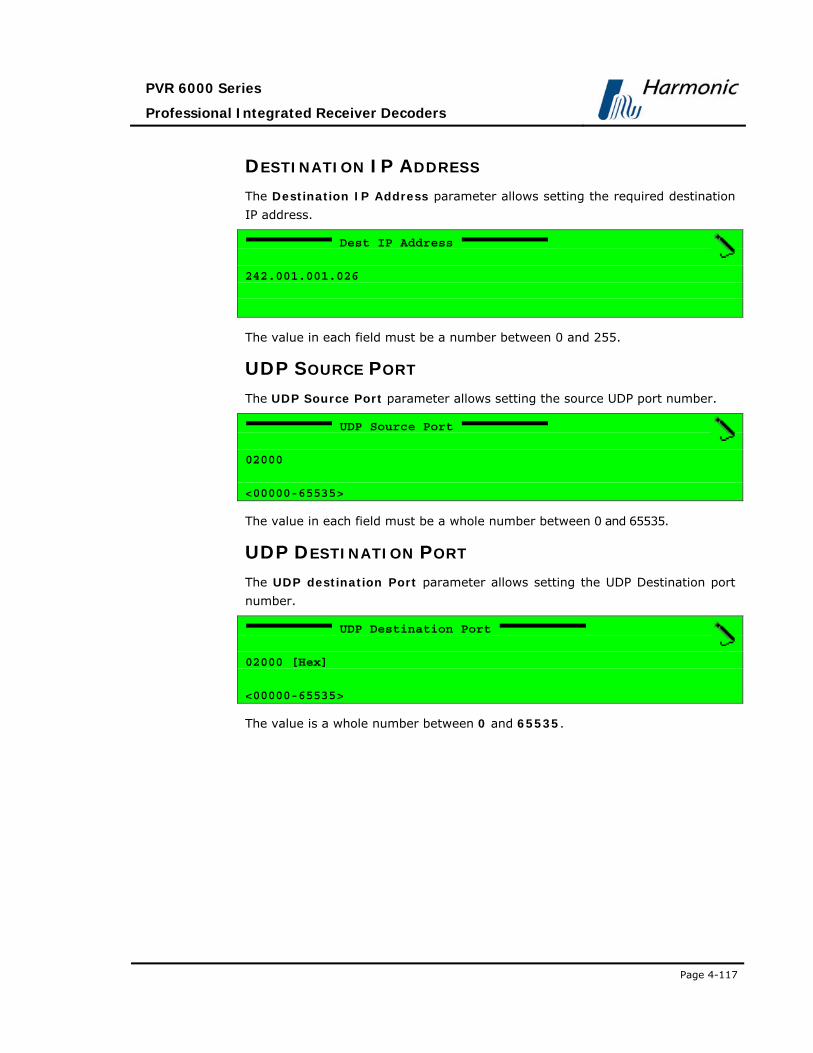
PVR 6000 Series
Professional Integrated Receiver Decoders
Page 4-117
DESTINATION IP ADDRESS The Destination IP Address parameter allows setting the required destination
IP address.
Dest IP Address
242.001.001.026
The value in each field must be a number between 0 and 255.
UDP SOURCE PORT The UDP Source Port parameter allows setting the source UDP port number.
UDP Source Port
02000
<00000-65535>
The value in each field must be a whole number between 0 and 65535.
UDP DESTINATION PORT The UDP destination Port parameter allows setting the UDP Destination port
number.
UDP Destination Port
02000 [Hex]
<00000-65535>
The value is a whole number between 0 and 65535.

User Manual
Operation and Management
Page 4-118 (Rev. 4.1/ SW v1.60/ December 2006)
NUMBER OF PACKETS The Number of Packets parameter allows setting the number of MPEG packets
to be contained in an IP frame (using the following Edit Value Screen).
Num of Packets
07
<01-07>
Available values are between 1 and 7.
4.2.8.3. High Speed Data
HS data is only supported in PVR 6000 and PVR 6060 models.
The High Speed Data Menu is used for setting the transfer rate & direction
(MSB↔LSB) and the type of data to be sent, through the High Speed Data port.
To access the High Speed Data Menu in the front panel control interface go to
Configuration Data High Speed Data Port.
Following is the corresponding front-panel screen:
High Speed Data 1-2-6-2
1 Tx Clock 08.307692 [Mb/s]
2 Tx Direction MSB -> LSB
3 Layer Filtering T.S PAYLOAD
The HS Data parameters are detailed as follows:
TX CLOCK The Tx Clock parameter sets the speed of the high speed data port.
Tx Clock
01.0 [Mb/s)
<00.064000 - 27.000000>
Legal values range from 00.064000 to 27.000000 Mbps.

PVR 6000 Series
Professional Integrated Receiver Decoders
Page 4-119
TX DIRECTION The Tx Direction parameter defines whether MSB or LSB is sent first.
Tx Directions
1 MSB -> LSB
2 LSB -> MSB
The available options are:
• MSB LSB – MSB sent first
• LSB MSB – LSB sent first
LAYER FILTERING The Layer Filtering parameter selects a filtering mode to data.
Layer Filtering
1 P.E.S PAYLOAD
2 T.S PAYLOAD
1 T.S PACKET
The available options are:
• P.E.S PAYLOAD – Strips the header of the packetized elementary stream
(PES).
• T.S PAYLOAD – Strips the transport stream header (first 4 bytes out of the
188 bytes packet)
• T.S PACKET – Enables the entire transport stream packet (188 bytes)

User Manual
Operation and Management
Page 4-120 (Rev. 4.1/ SW v1.60/ December 2006)
4.2.9. Conditional Access Configuration Menu This menu allows access to all PVR 6000 CA (Conditional Access) parameters.
Figure 4-26 displays a tree diagram of the Conditional Access Configuration
Menu.
Figure 4-26: Conditional Access Configuration Menu
ConditionalAccess
Common Interface BISS
Slot 1 / Slot 2
Send PIN Code
TV2 General
Root
Preset Configuration Status
Operation
Send MMICommand
Embedded
TV1
Even Key
Odd Key
Even Key
Odd Key
Encryption Mode
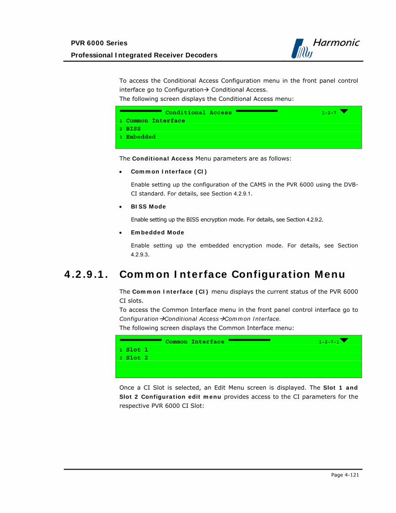
PVR 6000 Series
Professional Integrated Receiver Decoders
Page 4-121
To access the Conditional Access Configuration menu in the front panel control
interface go to Configuration Conditional Access.
The following screen displays the Conditional Access menu:
Conditional Access 1-2-7
1 Common Interface 2 BISS
3 Embedded
The Conditional Access Menu parameters are as follows:
• Common Interface (CI)
Enable setting up the configuration of the CAMS in the PVR 6000 using the DVB-
CI standard. For details, see Section 4.2.9.1.
• BISS Mode
Enable setting up the BISS encryption mode. For details, see Section 4.2.9.2.
• Embedded Mode
Enable setting up the embedded encryption mode. For details, see Section
4.2.9.3.
4.2.9.1. Common Interface Configuration Menu
The Common Interface (CI) menu displays the current status of the PVR 6000
CI slots.
To access the Common Interface menu in the front panel control interface go to
Configuration Conditional Access Common Interface.
The following screen displays the Common Interface menu:
Common Interface 1-2-7-1
1 Slot 1 2 Slot 2
Once a CI Slot is selected, an Edit Menu screen is displayed. The Slot 1 and
Slot 2 Configuration edit menu provides access to the CI parameters for the
respective PVR 6000 CI Slot:

User Manual
Operation and Management
Page 4-122 (Rev. 4.1/ SW v1.60/ December 2006)
Slot (1..2) 1-2-7-1-1
1 Operation ENABLE
2 Send MMI Command MENU-menu
3 Send PIN Code 1111
The following paragraphs detail the Slot Configuration options.
OPERATION The Operation parameter enables or disables the slot.
Operation
1 ENABLE
2 DISABLE
The available options are:
• ENABLE
• DISABLE
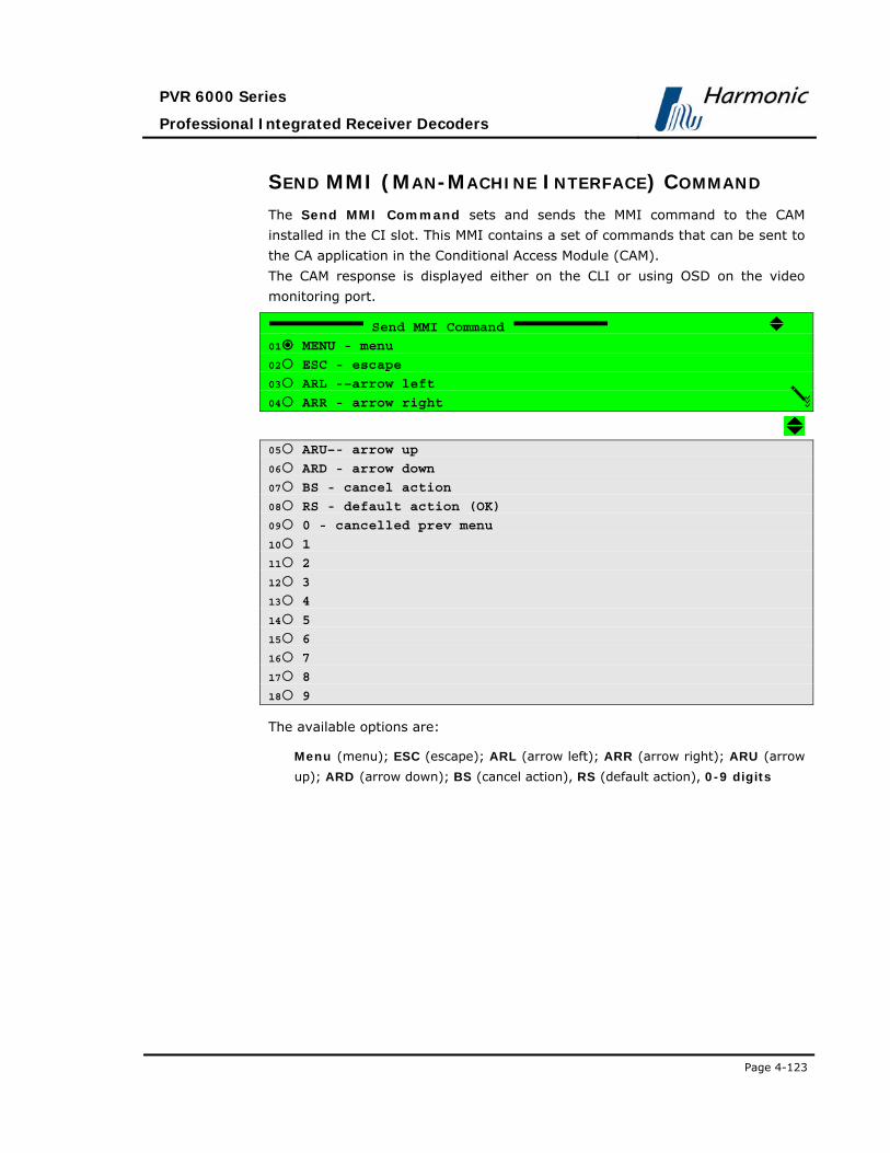
PVR 6000 Series
Professional Integrated Receiver Decoders
Page 4-123
SEND MMI (MAN-MACHINE INTERFACE) COMMAND The Send MMI Command sets and sends the MMI command to the CAM
installed in the CI slot. This MMI contains a set of commands that can be sent to
the CA application in the Conditional Access Module (CAM).
The CAM response is displayed either on the CLI or using OSD on the video
monitoring port.
Send MMI Command
01 MENU - menu
02 ESC - escape
03 ARL -–arrow left
04 ARR - arrow right
05 ARU–- arrow up
06 ARD - arrow down
07 BS - cancel action
08 RS - default action (OK)
09 0 - cancelled prev menu
10 1
11 2
12 3
13 4
14 5
15 6
16 7
17 8
18 9
The available options are:
Menu (menu); ESC (escape); ARL (arrow left); ARR (arrow right); ARU (arrow
up); ARD (arrow down); BS (cancel action), RS (default action), 0-9 digits

User Manual
Operation and Management
Page 4-124 (Rev. 4.1/ SW v1.60/ December 2006)
SEND PIN CODE The Send PIN Code parameter allows setting and sending a PIN code to the
CAM.
Send PIN Code
1111
<0000 - 9999>
4.2.9.2. BISS Mode
The PVR 6000 supports the following encryption modes:
• Even-Odd Encryption (‘Harmonic Inc. private’ mode)
• BISS Mode 1
• BISS-E Clear Session Word
• BISS-E with Injected ID
• BISS-E with Buried ID
The previously mentioned BISS options operate according to the EBU-UER Tech
3292 manual.
Even-Odd Encryption is a Harmonic Inc. developed encryption option that uses
both an even and an odd key. This is another encryption option that is available
for the operator.
The following screen displays the BISS menu navigation screen:
BISS 1-2-7-2
1 TV1
2 TV2 3 General
The BISS Menu parameters are:
• TV(1..2) - Enables the operator to set Encryption Keys values of the
selected input
• General – Allows the operator to select between the different encryption
modes
The following paragraphs detail the BISS parameters.

PVR 6000 Series
Professional Integrated Receiver Decoders
Page 4-125
TV1 The following screen displays the TV1 Edit Menu Screen:
TV1 1-2-7-2
1 Even Key 000000-000000
2 Odd Key 000000-000000
The TV1 menu available parameters are:
• Even Key
• Allows operator to set the Even Key encryption value
Even Key
000000-000000
• odd Key
• Allows operator to set the Odd Key encryption value
Odd Key
000000-000000
GENERAL The following screen displays the General Edit Menu Screen:
General 1-2-7-2-2
Encryption Mode EVEN-ODD
The General Menu parameters are:

User Manual
Operation and Management
Page 4-126 (Rev. 4.1/ SW v1.60/ December 2006)
ENCRYPTION MODE This screen allows the operator to select between the IRD’s different encryption
modes.
Encryption Mode
1 EVEN-ODD
2 BISS-MODE 1
3 BISS-E-CLEAR SW
4 BISS-E-INJECTED ID
05 BISS-E-BURIED ID
The available options are:
• EVEN-ODD
• BISS-MODE 1
• BISS-E-CLEAR SW
• BISS-E-INJECTED ID
• BISS-E-BURIED ID
4.2.9.3. Embedded Mode
This feature will be supported in the future software releases.

PVR 6000 Series
Professional Integrated Receiver Decoders
Page 4-127
4.2.10. Unit Configuration Menu The Unit Configuration Menu allows setting general PVR 6000 parameters.
Figure 4-27 displays a tree diagram of the Unit Configuration Menu.
Figure 4-27: Unit Configuration Menu
Unit
GeneralEthernet
ManagementPort
Root
Preset Configuration Status
LicensingSerial ControlPort
HW Interface
Address
LCD Contrast
SW Protocol
Baud Rate
Soft Reset
MAC Address
DefaultGateway
IP Address
Network Mask
Dry Contact
GPI 1 / GPI 2
HW Failure
Delay
Sync Loss
Test
Invalid PSI

User Manual
Operation and Management
Page 4-128 (Rev. 4.1/ SW v1.60/ December 2006)
To access the Unit Configuration Menu in the front panel control interface go to
Configuration Unit.
The following screen displays the Unit menu:
Unit 1-2-8
1 General 2 Serial Control Port
3 Ethernet Management Port
4 Licensing
5 Dry Contact
The Unit Configuration Menu parameters are as follows:
General Allows operator to set the LCD contrast value and perform soft reset (see
Section 4.2.10.1)
SERIAL CONTROL PORT Allows operator to configure the control port parameters (see Section 4.2.10.2)
ETHERNET MANAGEMENT PORT Allows operator to configure the Ethernet management port (see Section
4.2.10.4)
LICENSING Allows operator to activate features that require software license (see Section
4.2.10.5)
DRY CONTACT Allows operator to configure GPI-1 and GPI-2 parameters (see Section 0)

PVR 6000 Series
Professional Integrated Receiver Decoders
Page 4-129
4.2.10.1. General Configuration Menu
The General Menu adjusts the LCD contrast level and enables soft reset of the
device.
To access the General Menu in the front panel control interface go to
Configuration Unit General.
The following screen displays the General menu:
General 1-2-8-1
1 LCD Contrast 02[LEVEL]
2 Soft Reset OFF
The following paragraphs describe the General menu parameters.
LCD CONTRAST The LCD Contrast option sets the PVR 6000 LCD contrast.
LCD Contrast
02 [LEVEL]
<00 - 31>
Valid range is between 0 and 31, where 0 is brightest and 31 is darkest.
SOFT RESET This parameter is used for performing a warm reset on the PVR 6000.
Soft Reset
1 OFF
2 ON
The available options are:
• OFF
• ON – for performing soft reset
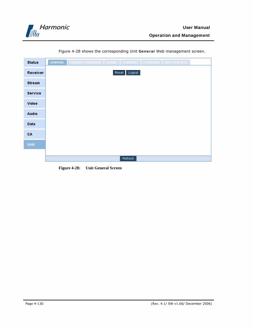
User Manual
Operation and Management
Page 4-130 (Rev. 4.1/ SW v1.60/ December 2006)
Figure 4-28 shows the corresponding Unit General Web management screen.
Figure 4-28: Unit General Screen
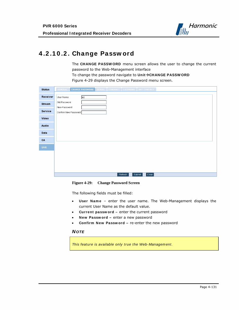
PVR 6000 Series
Professional Integrated Receiver Decoders
Page 4-131
4.2.10.2. Change Password
The CHANGE PASSWORD menu screen allows the user to change the current
password to the Web-Management interface
To change the password navigate to Unit CHANGE PASSWORD
Figure 4-29 displays the Change Password menu screen.
Figure 4-29: Change Password Screen
The following fields must be filled:
• User Name – enter the user name. The Web-Management displays the
current User Name as the default value.
• Current password – enter the current password
• New Password – enter a new password
• Confirm New Password – re-enter the new password
NOTE
This feature is available only true the Web-Management.

User Manual
Operation and Management
Page 4-132 (Rev. 4.1/ SW v1.60/ December 2006)
4.2.10.3. Serial Control Port Configuration
The Serial Control Port Menu allows the user setting the serial control port
parameters.
To access the Serial Control Port Menu in the front panel control interface go
to Configuration Unit Serial Control Port.
The following screen displays the Serial Control Port menu:
Serial Control Port 1-2-8-2
1 HW Interface RS232
2 SW Protocol TERMINAL ECHO
3 Baud Rate 115200 [Baud]
4 Address FFFF
Figure 4-30 shows the corresponding Unit Serial Web management screen.
Figure 4-30: Unit Serial Screen
The following paragraphs detail the Unit Serial Control Port configuration
options.

PVR 6000 Series
Professional Integrated Receiver Decoders
Page 4-133
HW INTERFACE HW Interface
1 RS232
2 RS485
The available options are:
• RS-232
• RS-485
SW PROTOCOL SW Protocol
1 TERMINAL ECHO
2 TERMINAL NO-ECHO
3 MASTER-SLAVE
The available options are:
• Terminal Echo
• Terminal No-Echo
• Master-Slave
BAUD RATE Baud Rate
1 4800 [Baud]
2 9600 [Baud]
3 19200 [Baud]
4 38400 [Baud]
5 57600 [Baud]
6 115200 [Baud]
The available options are:
4800, 9600, 19200, 38400, 57600, 115200 Baud

User Manual
Operation and Management
Page 4-134 (Rev. 4.1/ SW v1.60/ December 2006)
ADDRESS Address
FFFF [HEX]
<0000-FFFF>
Valid range is between 0 and FFFF (Hexadecimal).
4.2.10.4. Ethernet Management Port
The Ethernet Management Port Menu allows setting the Ethernet
management port parameters.
To access the Ethernet Management Menu in the front panel control interface
go to Configuration Unit Ethernet Management Port.
The following figure illustrates the Ethernet Management Port menu:
Ethernet 1-2-8-3
1 MAC Address 00-58-34-25-95-67
2 IP Address 010.008.000.216
3 Network Mask 255.255.255.000
4 Default Gateway 010.008.000.001

PVR 6000 Series
Professional Integrated Receiver Decoders
Page 4-135
Figure 4-31 shows the corresponding Unit Ethernet Web management screen.
Figure 4-31: Unit Ethernet Screen
The following paragraphs describe the Ethernet Management Port
Configuration parameters.
MAC ADDRESS The MAC Address parameter displays the MAC address of the PVR 6000
management.
IP ADDRESS The IP Address parameter displays and allows setting the currently active IP
Address of the management port

User Manual
Operation and Management
Page 4-136 (Rev. 4.1/ SW v1.60/ December 2006)
IP Address
010.008.000.216
The value in each field must be a number between 0 and 255.
NETWORK MASK The Network Mask parameter allows setting the network sub-mask.
Network Mask
255.255.255.000
The value in each field must be a number between 0 and 255.
DEFAULT GATEWAY The Default Gateway parameter allows setting the network default gateway
address. This is the address of a local IP router on the same network as the PVR
6000, which is used to forward traffic beyond the local network.
Default Gateway
010.008.000.001
The value in each field must be a whole number between 0 and 255.
4.2.10.5. Licensing Menu
The Licensing Menu screen allows the user to enable software-licensed features
by entering a serial number (key). The serial key can be entered thru the front
panel or the web-management. The serial key composed of 16 characters issued
by Harmonic Inc. video networks.
ENTERING A SRERIAL KEY THRU THE FRONT PANEL To enter a serial key thru the front panel access Key the Licensing menu
screen.

PVR 6000 Series
Professional Integrated Receiver Decoders
Page 4-137
Licensing
1-2-8-4
1 Key
00-00-00-00-00-0..
Use the [UP]/[DOWN] keys to change a characters value. User the
[LEFT]/[RIGH] keys to move to a different character.
Key
00-00-00-00-00-00-00-00
A licensing list is available at status menu screen. For details see section 4.3.8.4
ENTERING A SRERIAL KEY THRU THE WEB-MANAGMENT To enter a serial key thru the web-management access the Licensing tab at the
Unit menu screen. Fill in the appropriate field with the serial key.
Figure 4-32 displays the corresponding Licensing Web management screen.
Figure 4-32: PVR 6000 Licensing Screen

User Manual
Operation and Management
Page 4-138 (Rev. 4.1/ SW v1.60/ December 2006)
4.2.10.6. Dry Contact Menu
The Dry Contact menu allows selecting the GPI 1 or GPI 2 configuration menu.
The GPI (General Purpose Interface) is a dry contact relay, used by the PVR
6000 for displaying warnings that appear in the device. This is useful, for
example, in case the operator wants to receive an PVR 6000 warning indication
somewhere other than on the IRD’s display.
Dry Contact 1-2-8-5
1 GPI 1
2 GPI 2
Figure 4-33 displays the corresponding Dry Contact Web management screen.
Figure 4-33: PVR 6000 Dry Contact Screen
The GPI 1 and GPI 2 configuration menus are identical.
The following is the GPI 1 Edit Menu screen:

PVR 6000 Series
Professional Integrated Receiver Decoders
Page 4-139
GPI 1 1-2-8-5-1
1 Delay 000.0[sec]
2 Sync Loss OFF
3 HW Failure OFF
4 Invalid PSI OFF
5 Test
DELAY The PVR 6000 can delay warnings through the GPI.
Set the Delay parameter to a value between 0 (no delay) and 600 (in seconds).
Delay
000.0 [sec]
<000.0-600.0>
SYNC LOSS The Sync Loss menu defines whether or not a Sync Loss warning will cause a
GPI warning indication.
Sync Loss
1 OFF
2 ON
The available options are:
• OFF – Sync Loss GPI warning indication is turned off
• ON – Sync Loss GPI warning indication is turned on
HW FAILURE The HW Failure menu defines whether or not a Hardware Failure warning will
cause a GPI warning indication.
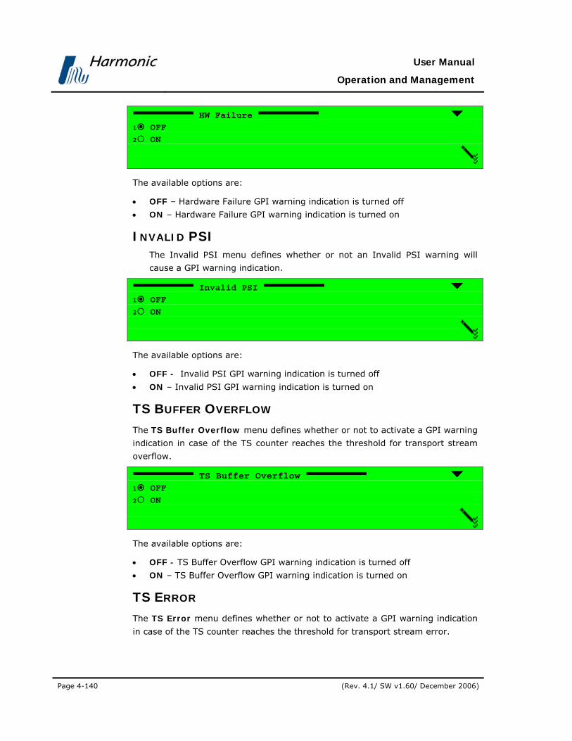
User Manual
Operation and Management
Page 4-140 (Rev. 4.1/ SW v1.60/ December 2006)
HW Failure
1 OFF
2 ON
The available options are:
• OFF – Hardware Failure GPI warning indication is turned off
• ON – Hardware Failure GPI warning indication is turned on
INVALID PSI The Invalid PSI menu defines whether or not an Invalid PSI warning will
cause a GPI warning indication.
Invalid PSI
1 OFF
2 ON
The available options are:
• OFF - Invalid PSI GPI warning indication is turned off
• ON – Invalid PSI GPI warning indication is turned on
TS BUFFER OVERFLOW The TS Buffer Overflow menu defines whether or not to activate a GPI warning
indication in case of the TS counter reaches the threshold for transport stream
overflow.
TS Buffer Overflow
1 OFF
2 ON
The available options are:
• OFF - TS Buffer Overflow GPI warning indication is turned off
• ON – TS Buffer Overflow GPI warning indication is turned on
TS ERROR The TS Error menu defines whether or not to activate a GPI warning indication
in case of the TS counter reaches the threshold for transport stream error.
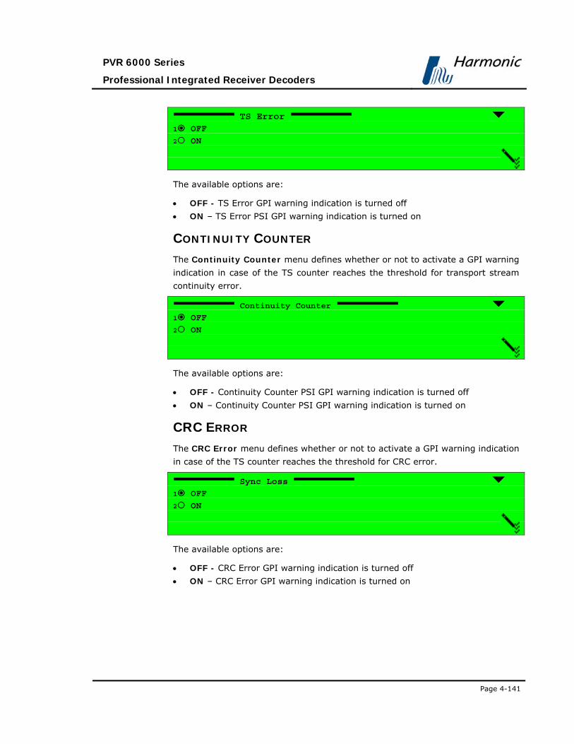
PVR 6000 Series
Professional Integrated Receiver Decoders
Page 4-141
TS Error
1 OFF
2 ON
The available options are:
• OFF - TS Error GPI warning indication is turned off
• ON – TS Error PSI GPI warning indication is turned on
CONTINUITY COUNTER The Continuity Counter menu defines whether or not to activate a GPI warning
indication in case of the TS counter reaches the threshold for transport stream
continuity error.
Continuity Counter
1 OFF
2 ON
The available options are:
• OFF - Continuity Counter PSI GPI warning indication is turned off
• ON – Continuity Counter PSI GPI warning indication is turned on
CRC ERROR The CRC Error menu defines whether or not to activate a GPI warning indication
in case of the TS counter reaches the threshold for CRC error.
Sync Loss
1 OFF
2 ON
The available options are:
• OFF - CRC Error GPI warning indication is turned off
• ON – CRC Error GPI warning indication is turned on
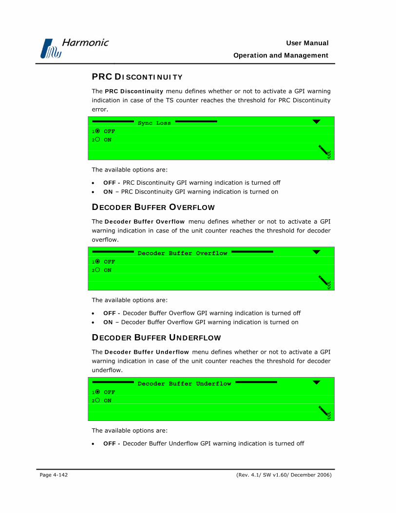
User Manual
Operation and Management
Page 4-142 (Rev. 4.1/ SW v1.60/ December 2006)
PRC DISCONTINUITY The PRC Discontinuity menu defines whether or not to activate a GPI warning
indication in case of the TS counter reaches the threshold for PRC Discontinuity
error.
Sync Loss
1 OFF
2 ON
The available options are:
• OFF - PRC Discontinuity GPI warning indication is turned off
• ON – PRC Discontinuity GPI warning indication is turned on
DECODER BUFFER OVERFLOW The Decoder Buffer Overflow menu defines whether or not to activate a GPI
warning indication in case of the unit counter reaches the threshold for decoder
overflow.
Decoder Buffer Overflow
1 OFF
2 ON
The available options are:
• OFF - Decoder Buffer Overflow GPI warning indication is turned off
• ON – Decoder Buffer Overflow GPI warning indication is turned on
DECODER BUFFER UNDERFLOW The Decoder Buffer Underflow menu defines whether or not to activate a GPI
warning indication in case of the unit counter reaches the threshold for decoder
underflow.
Decoder Buffer Underflow
1 OFF
2 ON
The available options are:
• OFF - Decoder Buffer Underflow GPI warning indication is turned off

PVR 6000 Series
Professional Integrated Receiver Decoders
Page 4-143
• ON – Decoder Buffer Underflow GPI warning indication is turned on
DECODER STREAM ERROR The Decoder Stream Error menu defines whether or not to activate a GPI
warning indication in case of the unit counter reaches the threshold for decoder
stream error.
Decoder Stream Error
1 OFF
2 ON
The available options are:
• OFF - Decoder Stream Error GPI warning indication is turned off
• ON – Decoder Stream Error GPI warning indication is turned on
TEST The Test menu allows operator to manually enable or disable the relevant GPI.
Test
1 OFF
2 ON
The available options are:
• OFF – Disables this GPI.
• ON – Enables this GPI.

User Manual
Operation and Management
Page 4-144 (Rev. 4.1/ SW v1.60/ December 2006)
4.3. STATUS The PVR 6000 allows the user to monitor different parameters statuses thru the
front panel or the web-management.
To access the PVR 6000 Status menu, select “Status” in the Root Menu
(navigate vertically by using the [Up]/[Down] arrow keys and confirm by
pressing [Enter]).
Root 1
1 Preset
2 Configuration
3 Status
The PVR 6000 Status Menu is displayed in the following menu navigation screen
(eight options):
Status 1-3
1 Receiver
2 Stream
3 Service
4 Video
5 Audio
6 Data
7 Conditional Access
8 Unit

PVR 6000 Series
Professional Integrated Receiver Decoders
Page 4-145
Figure 4-34 displays the corresponding Web management screen.
Figure 4-34: PVR 6000 Status Screen
4.3.1. Receiver Status The Receiver Status screen displays the main Receiver parameter current
values. The following paragraphs detail the Status screen of each available
receiver module type (DVB-S, DVB-S2, and IP).

User Manual
Operation and Management
Page 4-146 (Rev. 4.1/ SW v1.60/ December 2006)
To enter the Receiver Status menu in the front panel, go to Status Receiver
(independently of receiver module type).
4.3.1.1. DVB-S Receiver Status
To access the DVB-S Receiver Status Menu in the front panel control interface
go to Status Receiver.
NOTE
The LNB L.O. Frequency parameter is activated when the Ku and C-Band is
selected.
The following screen displays the DVB-S Receiver Status menu:
Receiver 1-2-1
1 Signal Quality 100[%]
2 Eb/N0 09.94[dB]
3 Link Margin +04.9dB]
4 Viterbi BER 0.0e-7
5 Frequency Tune 1.068000 [GHz]
6 Frequency Offset +02214[KHz]
7 Viterbi Rate 5/6
8 Spectral Inversion NORMAL
Figure 4-35 displays the corresponding Web management screen.
Figure 4-35: PVR 6000 DVBS Status Screen
The available options are:
• Signal Quality – Qualitative indicator of the received signal C/N relative to
the maximum C/N that can be measured without forcing the receiver to
saturation.

PVR 6000 Series
Professional Integrated Receiver Decoders
Page 4-147
Signal Quality
100 [%]
< 000 - 100 >
Values range from 0 to 100%
• Eb/N0 – Received signal Eb/N0 measurement
• Link Margin – Estimated C/N of the received signal relative to the C/N in
EN 300-421 for a given Viterbi rate
• Iturbi BER – Error bits that the Viterbi error correction did not correct. BER
is measured over 107 symbols.
• Frequency Tune – The value is dependent on the mode selected in Root
Configuration Receiver Freq Drift Compensation (see Section 4.2.2
and 7)
• When Frequency Drift Compensation is set to On, the value of the frequency
tune displays the frequency of the incoming signal after frequency offset is
set to off.
• When Frequency Drift Compensation is set to Off, the value of the frequency
tune displays the actual frequency.
NOTE
Displayed frequencies are L-Band frequencies.
• Frequency Offset - Displays the offset from the frequency as was set in
Configuration Receiver Frequency (see Section 4.2.2).
• When Frequency Drift Compensation is set to On, the frequency offset
displays the value 0.
• When Frequency Drift Compensation is set to Off, frequency offset displays
the value of the offset from the tuned frequency in KHz.
• Viterbi Rate – When Viterbi rate mode is set to automatic (see FEC Rate
parameter in section 4.2.2), the value displayed is selected by the PVR 6000.
The Viterbi rate can also be configured manually to a specific rate by the
operator.
• Spectral Inversion – When the Spectral Inversion mode is set to automatic
(see Section 4.2.2), the value displayed is PVR 6000 selected.
When you set the Spectral Inversion manually, the user selects the value.

User Manual
Operation and Management
Page 4-148 (Rev. 4.1/ SW v1.60/ December 2006)
4.3.1.2. DVB-S2 Receiver Status
To access the DVB-S2 Receiver Status Menu in front panel control interface go
to Status Receiver.
The following screen displays the DVB-S2 Receiver Status menu:
Receiver 1-3-1
1 Signal Quality 94[%]
2 Signal Level -8.00[dBm]
3 Eb/N0 21.10[dB]
4 BER 0.0e-7
5 Frequency Tune 1.000000 [GHz]
6 Frequency Offset +00011[KHz]
7 Modulation DVBS2-N-QPSK
8 FEC Rate 8/9
9 Roll-off 35%
10 Spectral Inversion NORMAL
Figure 4-36 displays the corresponding Web management screen.
Figure 4-36: PVR 6000 DVBS2 Status Screen
The Receiver Status screen contains the following parameters:
• Signal Quality – Qualitative indicator of the received signal C/N relative to
the maximum C/N that can be measured without forcing the receiver to
saturation. The signal quality is calculated by: SQ[%]=C/N [dB]/25 *100
Signal Quality
94 [%]
< 000 - 100 >
Signal Quality values range from 0 to 100%
• Signal Level – the signal power level in dBm
• BER – reports the estimated Bit Error Rate
• Eb/N0 – Received signal Eb/N0 measurement

PVR 6000 Series
Professional Integrated Receiver Decoders
Page 4-149
• Frequency Tune – This parameter points out the optimal frequency
checked by the PVR 6000 for obtaining the highest quality of the received
signal.
• Frequency Offset – displays the deviation between the frequency inserted
by the operator and the frequency that was indicated by the Frequency
Tune.
• Modulation – displays the configured modulation method
• FEC Rate – reports the selected FEC rate
• Roll Off – the configured Roll-Off factor value
• Spectral Inversion – When the Spectral Inversion mode is set to automatic
(see Section 4.2.2), the value displayed is the one selected by the device.
Otherwise, this parameter displays the Spectral Inversion method that was
selected manually.
NOTE
All displayed frequencies are in L-Band.
4.3.1.3. IP Receiver Status
The IP Receiver Status menu enables monitoring the main IP receiver
parameters. It displays both static information (such as MPEGoIP port MAC
Address) and live data (e.g. type of data encapsulation received, current bit
rate, whether or not IP parameters are valid, etc.).
To access the IP Receiver Status menu in the front panel interface go to
Status Receiver
The IP Receiver Status menu as displayed on the PVR 6000 front panel
screen:
Receiver 1-3-1
1 MPEGoIP Input 1
2 MPEGoIP Input 2
3 General
Figure 4-37displays the corresponding Web management screen.
Figure 4-37: PVR 6000 DVB IP Status Screen

User Manual
Operation and Management
Page 4-150 (Rev. 4.1/ SW v1.60/ December 2006)
The available options are:
• MPEGoIP Input 1 – for monitoring receiver data arriving through the
MPEGoIP IN1 interface
• MPEGoIP Input 2 - for monitoring receiver data arriving through the
MPEGoIP IN2 interface
• General – for viewing general parameters values, such as software and
hardware version number, IP configuration consistency, type of detected
encapsulation, bit-rate of currently received data, etc.
The following paragraphs detail the IP Receiver Status sub menus.
MPEGOIP INPUT 1 Below is an illustration of the MPEGoIP Input 1 menu as displayed on the PVR
6000 front panel screen:
MPEGoIP Input 1 1-3-1-1
1 MAC Address 00-78-34-25-9B-68
2 Physical Link Status Up/100Base-T/Full

PVR 6000 Series
Professional Integrated Receiver Decoders
Page 4-151
The MPEGoIP Input 1 Status parameters are:
• MAC Address – MPEGoIP IN1 port MAC address. The MAC address is a
unique, read-only address.
• Physical Link Status – current link status. The available options are:
• Down – Physical link is down
• Up – Physical link is up and connection is established
• 10Base-T, 100Base-T – IP Port data input rate
• Full – receiving in full duplex
• Half – receiving in half duplex
NOTE
MPEGoIP Input 2 Status parameters are identical to those of MPEGoIP Input
1 Status and provide information on MPEGoIP IN2 data.
GENERAL The IP Receiver Status General menu as displayed on the PVR 6000 front panel
screen:
General 1-3-1-3
1 HW Revision 53
2 SW Version dd/mm/yy mj.mn 18/08/05 01.05
3 Configuration OK
4 Active Input 1
5 Encapsulation UDP
6 MPEG Packet Size 188
7 Rx Bitrate Current 33.792093 [MHz]
The General menu parameters are:
• HW Revision – FPGA hardware Revision
• SW Version – software date and software version
• Configuration – displays “OK” if receiver configuration is valid, or
“Mismatch” if it has inconsistencies
• Active Input - the actual
• Receive Mode – displays “UDP” or “RTP” according to the type of received
data
• MPEG Packet Size – size of received packets (in bytes). Can be either 188
or 204 bytes
• Rx Bitrate Current – current rate of received data (in MHz)

User Manual
Operation and Management
Page 4-152 (Rev. 4.1/ SW v1.60/ December 2006)
4.3.2. Stream Status Menu The Stream Status Menu provides an extended menu of status monitoring
options on the input stream.
To access the Stream Status Menu in the front panel control interface go to
Status Stream.
The following screen displays the Stream Status menu:
Stream 1-3-2
1 Quality
2 Information
Figure 4-38displays the corresponding Web management screen.
Figure 4-38: PVR 6000 Stream Status Screen
4.3.2.1. Quality
The Quality Menu displays information about the quality of the Input Stream.
To access the Quality Menu in the front panel control interface go to
Status Stream Quality.
The following screen displays the Quality menu:
Quality 1-3-2-1
1 Sync-Ox47 Loss 000007
2 Continuity Counter 000006
3 T.S Fifo Overflow 000000
4 T.S Error Indicator 000007
5 ASI Input NOT DETECT
6 RS-422 Input NOT DETECT
The Quality Menu parameters are:
• Sync-0x47 Loss – Counts the number of sync loss events
• Continuity Counter – Counts the number of a continuity of error events
• TS FIFO overflow – Counts the number of FIFO buffer events
• TS Error Indicator – Counts the number of MPEG packets that were
received by the PVR 6000 and had the TS error indicator bit set

PVR 6000 Series
Professional Integrated Receiver Decoders
Page 4-153
• ASI Input.-. Has three modes:
• NOT DETECTED – No input
• 188 DETECTED – MPEG packets without FEC
• 204 DETECTED – MPEG packets with FEC
• RS-422 Input – Has three modes:
• NOT DETECTED – No input
• 188 DETECTED – MPEG packets without FEC
• 204 DETECTED – MPEG packets with FEC
4.3.2.2. Information
The Information Menu displays information about the transport stream and
network.
To access the Information Menu in the front panel control interface go to
Status Stream Information.
The following screen displays the Information menu:
Information 1-3-2-2
1 Transport Stream Rate 045.792 [Mbps]
2 Transport Stream ID 0005
3 Original Network ID 0888
4 Network Name CCTV
5 Stream Date 05-Oct-2004
6 Stream Time 14:23:19
The Information Menu parameters are as follows:
• Transport Stream Rate – Displays the Transport Stream rate
• Transport Stream ID – Displays the identification code of the current
transport stream ID in Hexadecimal values
• Original Network ID –Displays the identification code of the current
network in Hexadecimal values
• Network Name – Displays the provider name of the current network
• Stream Time – Displays the time (HH:MM:SS) of the current incoming
stream
• Stream Date – displays the date (DD-MMMM-YYYY) of the current incoming
stream

User Manual
Operation and Management
Page 4-154 (Rev. 4.1/ SW v1.60/ December 2006)
4.3.3. Service Status The Service Info is a section in the Status web-interface screen. It provides
information of service's status and parameters.
Figure 4-39 displays the Service Status Web management screen.
Figure 4-39: PVR 6000 Service Status Screen
The following parameters are displayed:
• TV – This parameter indicates the active decoder as TV1 (or TV1/TV2 in
case of a dual decoder unit).
• Service Name – This parameter displays the service's name.
• Service Type – This parameter indicates the service type: TV, Radio, TLTX,
NVOD, MOSAIC, PAL, SECAM, MAC, FM, NTSC, and Data.
• Service ID – This parameter displays the service identification symbol
[Hex].
• Service Mode - Indicates if the service is encrypted (CAS) or free to air
(FTA).
• Active in PAT – this parameter indicates whether the service is included in
the PAT table or not.
4.3.4. Video Status Menu The Video Status Menu displays the status of Video and VBI parameters.
OSD parameter status will be available in future software versions.
The Video Status Menu provides an extended menu of status monitoring
options on Video and VBI data.
To access the Video Status Menu in the front panel control interface go to
Status Video.
The following screen displays the Video Status menu:
Video 1-3-4
1 Video 1
2 VBI 1
3 Video 2
4 VBI 2
Figure 4-40 displays the corresponding Web management screen.
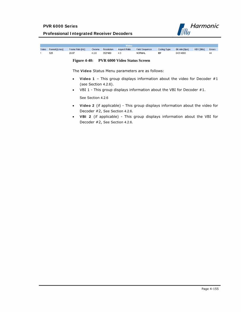
PVR 6000 Series
Professional Integrated Receiver Decoders
Page 4-155
Figure 4-40: PVR 6000 Video Status Screen
The Video Status Menu parameters are as follows:
• Video 1 – This group displays information about the video for Decoder #1
(see Section 4.2.6).
• VBI 1 - This group displays information about the VBI for Decoder #1.
See Section 4.2.6
• Video 2 (if applicable) - This group displays information about the video for
Decoder #2, See Section 4.2.6.
• VBI 2 (if applicable) - This group displays information about the VBI for
Decoder #2, See Section 4.2.6.

User Manual
Operation and Management
Page 4-156 (Rev. 4.1/ SW v1.60/ December 2006)
4.3.4.1. Video 1 (and Video 2)
The Video 1 Menus (and Video 2 in dual decoder IRDs) display video
parameter Statuses.
To access the Video 1 Menu in the front panel control interface go to
Status Video Video 1.
The following screen displays the Video 1 menu:
Video 1 1-3-4-1
1 Standard Format 625 [Ln]
2 Frame Rate 25 [Hz]
3 Chroma Format 4:2:0
4 Resolution H:720 * V:608
5 Aspect Ratio 4:3
6 Field Sequence NORMAL
7 Picture Coding Type P-B
8 Bit Rat 11080800 [Bps]e
9 VBV Buffer Size 04096000 [Bit]
10 Decoding Errors 000000
NOTE
The "Decoding Errors" parameter indicates the video stream health.
The available information is:
• Standard Format – Indicates the number of lines in the incoming video.
In this example, 625 lines indicate PAL video format.
• Frame Rate – Displays the frame rate of the incoming video stream
• Chroma Format – Displays the Chroma format currently used for the
incoming video stream
• Resolution – Displays the horizontal and vertical video resolutions for
the incoming video stream (for example, the number of pixels per
horizontal and vertical screen lines)
• Aspect Ratio – Displays the aspect ratio for the incoming video stream
• Field Sequence – Displays the type of field sequence found in the
decoded service. There are two available values: Normal, and 3:2
Pulldown

PVR 6000 Series
Professional Integrated Receiver Decoders
Page 4-157
• Picture Coding Type – displays the types of picture coding that were
found in the decoded service. Available picture coding types are: I-B-P,
I-P, P-B and P Only.
• Bit Rate – Displays the bit rate, in bits/sec, for the incoming video
stream
• VBV Buffer Size – Displays the VBV buffer size
• Decoding Errors – Displays the total number of decoding errors
4.3.4.2. VBI 1 (and VBI 2)
The VBI 1 Menu (and VBI 2 in dual decoder IRD’s) display VBI parameters
Status.
To access the VBI 1 Menu in the front panel control interface go to
Status Video Vbi 1.
The following screen displays the VBI 1 menu:
Vbi (1..2) 1-3-4-2
1 Video Fullness 020 [%]
2 E.S Fullness 012 [%]
3 E.S Top Num Lines 05 [Ln]
4 E.S Bottom Num Lines 05 [Ln]
The available information is:
• Video Fullness – Fullness level of the buffer containing VBIs derived from
the video stream
• E.S Fullness – Fullness of the buffer containing VBIs derived from the
elementary stream
• E.S Top Num Lines – Counts the number of E.S VBI lines in a field
• E.S Bottom Num Lines – Counts the number of E.S VBI lines in a field

User Manual
Operation and Management
Page 4-158 (Rev. 4.1/ SW v1.60/ December 2006)
4.3.5. Audio Status Menu The Audio Status Menu displays information on the audio channels.
To access the Audio Status Menu in the front panel control interface go to
Status Audio.
The following screen displays the Audio Status menu:
Audio 1-3-5
1 Audio 1
2 Audio 2
3 Audio 3
4 Audio 1
4.3.5.1. Audio (1..4)
Select Audio 1 through 4.
The Audio (1..4) Menu displays information on the audio decoding process.
When Musicam mode is activated, the following screen is displayed:
Audio (1..4) 1-3-5-1
1 ID MPEG
2 Layer LAYER2
3 Bit Rate 129000 [Bps]
4 Sample Rate 48 [KHz]
5 Mode STEREO
6 Decoding Errors 000894
Figure 4-41 displays the corresponding Web management screen.
Figure 4-41: PVR 6000 Audio Status Screen

PVR 6000 Series
Professional Integrated Receiver Decoders
Page 4-159
NOTE
The "Decoding Errors" parameter indicates the video stream health.
When Dolby-AC3 mode is activated, the following screen is displayed:
Audio (1..4) 1-3-5-1
1 ID DOLBY AC3
2 Bit Rate 128000[Bps]
3 Sample Rate 48[KHz]
4 AC Mode 2/0 L,R STEREO
5 BS Mode COMPLETE MAIN
6 Decoding Errors 083914
When Linear PCM mode is activated, the screen below is displayed:
Audio (1..4) 1-3-5-1
1 ID LINEAR
2 Sample Rate 48 [KHz]
3 Bits per Sample 20 BITS
4 Channel ID 2
5 Output Mode 2/0 L,R
6 Decoding Errors 0003
NOTE
The Channel ID parameter value is according to the channel number of the AC3
header.

User Manual
Operation and Management
Page 4-160 (Rev. 4.1/ SW v1.60/ December 2006)
4.3.6. Data Status Menu The Data Status Menu displays information about the data input stream.
To access the Data Status Menu in the front panel control interface go to
Status Data.
The following screen displays the Data Status menu:
The High Speed Data Port option is supported only in the PVR 6000 and PVR
6060 models. In these models, the following is the corresponding front panel
screen:
Data 1-3-6
1 Low Speed Data Port
2 High Speed Data Port
IP-Out-Port is supported in all PVR 6000 models, except for the PVR 6000 and
PVR 6060 models. For these models, the Data Status menu is displayed as
follows:
Data 1-3-6
1 Low Speed Data Port 2 IP Out Port
The Data Status menu parameters are as follows:
• Low Speed Data Port – See Section 4.3.6.1.
• High Speed Data Port – See Section 4.3.6.2.
• IP Out Port – See Section 4.3.6.3.
4.3.6.1. Low Speed Data Port This feature will be supported in the future software releases.
4.3.6.2. High Speed Data Port This feature will be supported in the future software releases.
4.3.6.3. IP-Out-Port Status Menu The IP-Out-Port Status Menu provides IP and Port related parameter statuses.
To access the IP-Out-Port Status Menu in the front panel control interface go
to Status Data IP Output Port.
The following screen displays the Output Port Status menu:
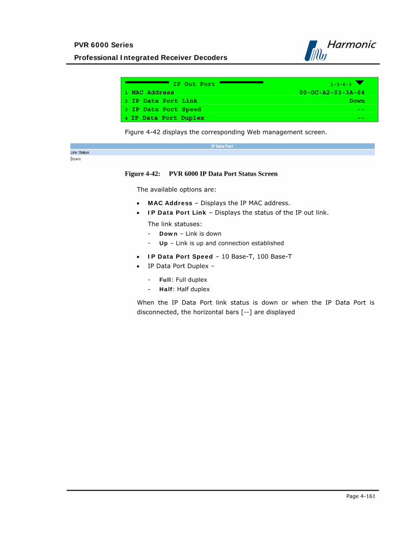
PVR 6000 Series
Professional Integrated Receiver Decoders
Page 4-161
IP Out Port 1-3-6-3
1 MAC Address 00-OC-A2-03-3A-64
2 IP Data Port Link Down
3 IP Data Port Speed --
4 IP Data Port Duplex --
Figure 4-42 displays the corresponding Web management screen.
Figure 4-42: PVR 6000 IP Data Port Status Screen
The available options are:
• MAC Address – Displays the IP MAC address.
• IP Data Port Link – Displays the status of the IP out link.
The link statuses:
- Down – Link is down
- Up – Link is up and connection established
• IP Data Port Speed – 10 Base-T, 100 Base-T
• IP Data Port Duplex –
- Full: Full duplex
- Half: Half duplex
When the IP Data Port link status is down or when the IP Data Port is
disconnected, the horizontal bars [--] are displayed

User Manual
Operation and Management
Page 4-162 (Rev. 4.1/ SW v1.60/ December 2006)
4.3.7. Conditional Access Status Menu The Conditional Access Status Menu allows viewing Conditional Access
parameter statuses.
To access the Conditional Access Status Menu in the front panel control
interface go to Status Conditional Access
The following screen displays the Conditional Access Status menu:
Conditional Access 1-3-7
1 Common Interface
2 BISS
3 Embedded
CAUTION
The Conditional Access Status menu must be handled by qualified users who are
familiar with the DVB-C2 standard and protocols.
COMMON INTERFACE The Common Interface Menu displays information on the CAMs inserted to the
PVR 6000 CI Slot. The status menu for Slot 1 and Slot 2 is identical unless one
of the CI Slots is not equipped with a CAM.
To access the Common Interface Menu in the front panel control interface go
to Status Conditional Access Common Interface.
The following screen displays the Common Interface Status menu:
Common Interface 1-3-7-1
1 Slot1
2 Slot2

PVR 6000 Series
Professional Integrated Receiver Decoders
Page 4-163
SLOT (1..2) The Slot (1..2) Menu displays information on a CAM in Slot (1..2).
To access the Slot 1 Menu in the front panel control interface go to
Status Conditional Access Common Interface Slot 1.
The following screen displays the Slot 1 Status menu:
Slot (1..2) 1-3-7-1-1
1 Card Type DVB CI Module
2 Applic Manufacture 2200
3 Manufacture Code 2200
4 Main Menu CodiCrypt
5 Available Sessions
6 Supported CA SysID
The available options are:
• Card Type – Displays card type
• Applic Manufacture – Displays application manufacturer value
• Manufacture Code – Displays the manufacturer code, defined by the CAM
manufacturer.
• Main Menu – Displays CA vendor name
• Available Sessions – Displays currently available sessions.
The following screen displays the Available Sessions Table menu:
Session Resource ID Resource
1 0001 00010041 MANAGER
2 0002 00020041 AI
3 0003 00030041 CAS
4 0004 00240041 DATA-TIME
5 0005 00400041 MMI
• Supported CA SysID - Displays supported CA SysID.

User Manual
Operation and Management
Page 4-164 (Rev. 4.1/ SW v1.60/ December 2006)
The following screen displays the Supported CA SysID Table menu:
System ID CA Specifier
01 2200 Scopus
02 2201 Scopus
03 2202 Scopus
04 2203 Scopus
05 2204 Scopus
06 2205 Scopus
07 2206 Scopus
08 2207 Scopus
09 2208 Scopus
10 2209 Scopus
11 220A Scopus
12 220B Scopus
13 220C Scopus
14 220D Scopus
15 220E Scopus
16 220F Scopus
NOTE
To see Available Sessions and supported CA SysID values, select an item and
press [Enter].
B. BISS This feature will be supported in future software releases.
C. EMBEDDED This feature will be supported in future software releases.

PVR 6000 Series
Professional Integrated Receiver Decoders
Page 4-165
4.3.8. Unit Status Menu This menu displays the Unit Menu parameters status.
To access the Unit menu in the front panel control interface go to Status Unit.
T he following screen displays the Unit Status menu:
Unit 1-3-8
1 Identity
2 Versions
3 Monitoring
Figure 4-43 displays the corresponding Web management screen.
Figure 4-43: PVR 6000 Unit Status Screen
4.3.8.1. Identity
The Identity Menu displays information regarding the PVR 6000 hardware.
To access the Identity Menu in the front panel control interface go to
Status Unit Identity
The following screen displays the Identity Status menu:
Identity 1-3-8-1
1 Configuration ID PVR 600x 2 Serial Number 00000920
3 Decoder Board SPN-29 REV-C
4 Front-End Board QPSK-29 REV-A
The available options are:
• Configuration ID – Displays the PVR 6000 software configuration model as
recognized by the software. Note that the configuration ID may not be
identical to the PVR 6000 model number as printed on the front panel.
• Serial Number – Displays the PVR 6000 serial number

User Manual
Operation and Management
Page 4-166 (Rev. 4.1/ SW v1.60/ December 2006)
• Decoder Board – Displays the hardware revision of the PVR 6000 main
board
• Front-End Board – Displays the hardware revision of the PVR 6000 Front-
End
Figure 4-44 displays the corresponding Web management screen.
Figure 4-44: Unit – Identity (Status Screen)
4.3.8.2. Versions
The Version Menu displays information on the PVR 6000 software versions.
To access the Versions Menu in the front panel control interface go to
Status Unit Versions.
The following screen displays the Versions Status menu:
Versions 1-3-8-2
1 Boot Application 00.03
2 Main Application 00.07
3 Main Application Date Dec 19 2004
4 Main Application Time 15:50:26
The available options are:
• Boot Application – Displays the boot application software version
• Main Application – Displays the main application software version
• Main Application Date – Displays the date when the main application was
created
• Main Application Time – Displays the time when the main application was
created
Figure 4-45 displays the corresponding Web management screen.
Figure 4-45: Unit – Versions (Status Screen)
4.3.8.3. Monitoring
The Monitoring Menu displays temperature and management port statuses.
To access the Monitoring Menu in the front panel control interface go to
Status Unit Monitoring.
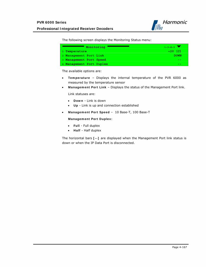
PVR 6000 Series
Professional Integrated Receiver Decoders
Page 4-167
The following screen displays the Monitoring Status menu:
Monitoring 1-3-8-3
1 Temperature +20 [C]
2 Management Port Link DOWN
3 Management Port Speed --
4 Management Port Duplex --
The available options are:
• Temperature – Displays the internal temperature of the PVR 6000 as
measured by the temperature sensor
• Management Port Link – Displays the status of the Management Port link.
Link statuses are:
• Down - Link is down
• Up - Link is up and connection established
• Management Port Speed – 10 Base-T, 100 Base-T
Management Port Duplex:
• Full - Full duplex
• Half - Half duplex
The horizontal bars [--] are displayed when the Management Port link status is
down or when the IP Data Port is disconnected.

User Manual
Operation and Management
Page 4-168 (Rev. 4.1/ SW v1.60/ December 2006)
4.3.8.4. Licensing
The Licensing screen displays all features and their operational status.
Licensing
1-2-2-4-2
01 ASI Input YES
02 ASI Output YES
03 MPEGoIP/MPE Output YES
04 GENLOCK YES
05 Audio 3 YES
06 Audio 4 YES
07 LSD<RS232> YES
08 DOLBY Audio1 Decoding YES
09 DOLBY Audio2 Decoding YES
10 DOLBY Audio3 Decoding YES
11 DOLBY Audio4 Decoding YES
12 Linear Audio 1 Decoding YES
13 Linear Audio 2 Decoding YES
14 Linear Audio 3 Decoding YES
15 Linear Audio 4 Decoding YES
16 PID Filtering YES
17 MPEG4 H.264 YES

PVR 6000 Series
Professional Integrated Receiver Decoders
Page A-1
Appendix A SOFTWARE DOWNLOAD
A.1 DOWNLOADING SOFTWARE USING FTP
A.1.1 Introduction
A.1.1.1 PVR 6000 SETUP IP
Configure the PVR 6000 IP Management Port according to local network
specifications. The PVR 6000 IP Management is configured from the front-panel
by accessing Configuration Unit Ethernet Management Port.
The IP Management must set the following parameters: IP Address, Network
Mask, and Gateway.
A.1.1.2 PC FTP Application
There are many PC Software Applications that support FTP.
In this document, software download procedure is performed using the built-in
MS Windows FTP utility.
NOTE
Viewing the PVR 6000 version is available through the front-panel by selecting
Status Unit Versions Main Application.
A.1.2 Installation
A.1.2.1 Loading Through FTP
To open an FTP session, perform the following:
1. Click Start. The Start Menu is displayed.
From the Start Menu click Run. The Run dialog box is displayed.

User Manual Appendix A
Software Download
Page A-2 (Rev. 4.1/ SW v1.60/ December 2006)
Figure A-1: Start Menu – Select Run
3. Type “cmd” in the combo-box and click OK. The terminal window is
displayed.

PVR 6000 Series
Professional Integrated Receiver Decoders
Page A-3
Figure A-2: Run Dialog Box
4. Type “ftp <PVR 6000 Management IP address>” and press [Enter].
FTP session is displayed. See the following example.
Figure A-3: Open FTP Session
LOG ON 1. Log on to the PVR 6000 with the user name and password, both are empty
for the IRD.
2. Reply with [Enter] for both user and password requests.

User Manual Appendix A
Software Download
Page A-4 (Rev. 4.1/ SW v1.60/ December 2006)
Figure A-4: Login to FTP
3. After connecting to the PVR 6000 through FTP, type “bin” and Click [Enter].
Figure A-5: Access Bin Folder

PVR 6000 Series
Professional Integrated Receiver Decoders
Page A-5
LOADING THE FILE To load a source file from a local PC to the PVR 6000:
1. Type put and click [Enter]
2. After Local File, type the file name with the suffix (Notice - the software
file name and path in the PC should be known).
3. After Remote File, type ‘/rom/sw_image.bin’.
Figure A-6: Loading the File
After confirmation, the PVR 6000 progress is displayed in a loading screen on
the PVR 6000 front-panel. In the left frame window the loading progress is
indicated by a percentage and blinking progress bar. Following is the PVR 6000
loading screen:

User Manual Appendix A
Software Download
Page A-6 (Rev. 4.1/ SW v1.60/ December 2006)
WARNING
IF THE PVR 6000 IS, FOR ANY REASON, SHUT DOWN DURING
SOFTWARE DOWNLOAD, THE PROGRAM MUST BE REINSTALLED
THROUGH BOOT SOFTWARE DOWNLOAD. REINSTALLATION IS
AVAILABLE THROUGH RS-232. SEE SECTION A.2.2.2.
A.2 LOADING SOFTWARE TO THE PVR 6000
THROUGH THE SERIAL PORT
A.2.1.1 PC Connection to the Serial Port
The PVR 6000 can be controlled from a standard PC through a serial RS-232 or
RS-485 cable. Table A- and Table A-2 detail the pin-to-pin and signal
assignments of the RS-232 and RS-485 cables, respectively.
Table A-1: RS-232 Control Cable Pin-to-Pin
9 PIN D-TYPE CONNECTOR
(PC) 9 PIN D-TYPE CONNECTOR
(IRD) SIGNAL DESCRIPTION
2 3 Pc-RxD
3 2 Pc-RxD
5 5 GND

PVR 6000 Series
Professional Integrated Receiver Decoders
Page A-7
Table A-2: RS-485 Control Cable Pin-to-Pin Designations
PC RS-485 9 PIN D-TYPE CONNECTOR
PVR 6000 RS-485 9 PIN D-TYPE CONNECTOR
PIN DESIGNATIONS PIN DESIGNATIONS
1 RB 1 TX+
6 RA 6 TX-
8 TB 8 RX+
9 TA 0 RX-
A.2.1.2 PC Serial-COM (Terminal) Software
There are many Terminal Applications that support Serial-COM.
In this document Software download procedure is performed on the built-in MS
Windows hyperterminal.
A.2.1.3 Opening Hyperterminal from MS Windows
1. Access HyperTerminal application, by selecting
Start Program Accessories Communication HyperTerminal

User Manual Appendix A
Software Download
Page A-8 (Rev. 4.1/ SW v1.60/ December 2006)
Figure A-7: Start Menu – Open HyperTerminal
A.2.1.4 Defining the Communication
When the HyperTerminal starts, the following window is displayed.
Enter a connection, for example PVR 6000 and lick OK.
Select a connection (Icon).

PVR 6000 Series
Professional Integrated Receiver Decoders
Page A-9
Figure A-8: HyperTerminal – Enter Connection
3. Select a PC COM port that is the specific PC COM to which the PVR 6000 is
connected.
Figure A-9: Select PC COM Port

User Manual Appendix A
Software Download
Page A-10 (Rev. 4.1/ SW v1.60/ December 2006)
4. Select the Baud Rate. This must be identical to the PVR 6000 baud rate
parameter. See Configuration Unit Serial Control Port Baud Rate.
5. Select Flow Control – None.
Figure A-10: Port Settings Tab
A.2.1.5 Checking PC Terminal Communication with the IRD
After setting the PC - HyperTerminal, the Terminal is opened and the user can
check the connection to the IRD on the HyperT erminal.
Press [Enter]. If the word “Root” appears on the terminal window, the user is
connected with the IRD. /root> indicates the main path to the IRD.
The user can also type “help” to see the PVR 6000 help commands.

PVR 6000 Series
Professional Integrated Receiver Decoders
Page A-11
Figure A-11: HyperTerminal Window
The user can check the current PVR 6000 version with command
“status/unit/sw_info” or select the Status Unit Versions Main
Application on the front panel.

User Manual Appendix A
Software Download
Page A-12 (Rev. 4.1/ SW v1.60/ December 2006)
A.2.2 INSTALLATION:
A.2.2.1 Loading new Software Sequence
1. After the PC-to-PVR 6000 Communication is checked, in the Root directory
type “config/unit/upgrade_sw” and confirm by typing “yes”.
Figure A-12: Update Software Version Command

PVR 6000 Series
Professional Integrated Receiver Decoders
Page A-13
The PVR 6000 erases the previous software version when updating. This process
can take approximately 30 seconds (see the following example).
Figure A-13: Erasing Flash Process
After the previous software is erased, message “Ready For Receive” is
displayed.
2. In the HyperTerminal, select Transfer send file.

User Manual Appendix A
Software Download
Page A-14 (Rev. 4.1/ SW v1.60/ December 2006)
Figure A-14: Ready to Receive New Software
3. Specify to which used protocol to send the software file. It can be
“Xmodem” or “1K Xmodem” protocol.
NOTE
“1K Xmodem” is faster than “XModem”.
4. Specify the path of the software file on your PC, for example:

PVR 6000 Series
Professional Integrated Receiver Decoders
Page A-15
Figure A-15: Send File Dialog Box
5. Click Send. The loading starts. This may take a few minutes.
The status is displayed in the following window below or on the PVR 6000 front
panel main menu.
Figure A-16: Sending Status Dialog Box
When the process is complete, a confirmation is displayed, indicating that the file
was loaded. Then the PVR 6000 performs reboot.

User Manual Appendix A
Software Download
Page A-16 (Rev. 4.1/ SW v1.60/ December 2006)
6. Wait until the PVR 6000 is finished rebooting the new software.
7. On the front panel, verify that the new version is installed.
A.2.2.2 Loading Software Version through PVR 6000 BOOT Application
When the PVR 6000 is shut down during software download, the PVR 6000 start
up sequence is set with the boot application. Perform the following:
1. Stop the previous Hyper Terminal sending process and restart standard
communication with the IRD.
2. When the PVR 6000 starts the BOOT application, the following hyperterminal
window is displayed.
Figure A-17: IRD Boot Application Starts
The following screen displays the PVR 6000 Boot Software download menu:

PVR 6000 Series
Professional Integrated Receiver Decoders
Page A-17
MPEG-2 DVB/ATSC I.R.D - BOOT APPLICATION
UPGRADE Thru’ SERIAL - Progress = 14%
After download is complete, the PVR 6000 restarts the standard operation with
the new software version.
3. To use the Boot Application, type “upgrade_sw applic”. The PVR 6000
starts "erasing flash" and after few minutes (after Erasing Flash Completed
Successfully) the “Ready for Receive...” message is displayed. Continue
loading the new version according to the standard procedure.
Figure A-18: Complete Software Loading


PVR 6000 Series
Professional Integrated Receiver Decoders
Page B-1
Appendix B IP-FRONT END SOFTWARE UPGRADE PROCEDURE
This appendix details the software upgrade procedure in an IP front end PVR
6000 device. This procedure is different than in other front end devices.
To perform the IP Front End software upgrade, perform the following steps:
1. The watchdog feature must first be disabled in the PVR 6000 for correct SW
upgrade. To disable the watchdog feature, perform the following steps:
• In the PVR 6000 front panel, go to Configuration Stream Source
and select Serial RS422
• In the command prompt (Start Run) on the PC enter ’telnet <device
IP address> 1023. Note: To obtain the <device IP address> in the PVR
6000 front panel, go to Configuration Receiver MPEGoIP Input 1
(or 2) Physical Link and copy the number from the IP Address
parameter.
• In the Telnet prompt, press Enter.
• In the Telnet prompt, type 'dwd'.
• Power off the PVR 6000
• After a few seconds, power on the PVR 6000. The watchdog function is
now off.
2. For each new SW upgrade obtain a self extracting software upgrade file.
3. Create a new directory under drive C:\ and name it NEW_VER.
4. Copy the self extracting file into the NEW_VER directory.
5. Go to Start Run and enter ‘cmd’.
6. In the command prompt window enter ‘cd \NEW_VER’.
7. Type the name of the SW upgrade self-extracting EXE file and press Enter
8. Answer any questions that may be displayed on the command prompt
window with ‘Y’ followed by Enter
9. After the self extracting file has finished the self extraction, run the file
called ‘update.bat’ from this same directory, then enter the PVR 6000 IP
address. Obtain the IP address by accessing
Configuration Receiver MPEGoIP Input 1 (or 2) Physical Link in
the front panel. Then copy the address from the IP Address parameter. For
example ‘update 10.100.1.26’.

User Manual Appendix B
IP-Front End Software Upgrade Procedure
Page B-2 (Rev. 4.1/ SW v1.60/ December 2006)
10. In the Telnet prompt window, type ‘telnet <unit IP Address> 1023’ (use the
same IP Address as in step 9).
11. Type 'exit' and then Enter.
12. Type ' burn “vxw” ' and then Enter.
13. Type ' “burn “ird” ' and then Enter.
14. Power off the PVR 6000.
15. After a few seconds, power on the PVR 6000.
16. On the PVR 6000 front panel, go to Configuration Stream Source and
select FRONT END (IP)
17. Verify the correct upgrading of the new SW version by going in the PVR
6000 front panel to Status Receiver General and checking the SW Version
dd/mm/yy mj.mn parameter value
NOTE
If power failure occurs during upgrade, repeat the upgrade from step 1

PVR 6000 Series
Professional Integrated Receiver Decoders
Page C-1
Appendix C ASPECT RATIO CONFIGURATION PROCESS
C.1 GENERAL This Appendix details PVR 6000 configuring for the fitting of Aspect Ratio (A/R)
of the incoming Video to the A/R of the destination monitor.
C.2 ASPECT RATIO CONVERSION MACHINE The PVR 6000 provides the ability, using interpolation, to produce different
image formats, enabling the display of the incoming Video on either a 4:3 or a
16:9 monitor.
16:9 Video Streams can be fitted for display on 4:3 monitors, and vice versa, in
more than one format, as summarized in Table C-1 and Table C-2.
A/R fitting is referred to as Conversion. The PVR 6000 contains an “Aspect
Ratio Conversion Machine” responsible for all image conversions.
Figure C-1 displays a simplified illustration of this machine.
Figure C-1: Aspect Ratio Conversion Machine

User Manual Appendix C
Aspect Ratio Configuration Process
Page C-2 (Rev. 4.1/ SW v1.60/ December 2006)
When fitting the received Video signal A/R to the monitor A/R, the following
three PVR 6000 parameters values must be set to achieve the required
conversion:
• WSS
• Monitor Aspect Ratio
• Interpolation
WSS (WIDE SCREEN SIGNALING) The purpose of the WSS signal is to inform the destination monitor of the
received Video A/R. The PVR 6000 extracts the WSS information from an
operator-selected source, generates a new WSS signal (see ‘WSS Signal
Generator’ in Figure C-1), and outputs it to the monitor.
The WSS menu in the PVR 6000 contains two items:
• Source – from which the PVR 6000 extracts the WSS information. The
available options are: DISABLE, TV MONITOR, E.S. (EN-301-775), and
VIDEO (see WSS explanation in Section 4.2.6.2 for further details).
• Line1 – Video line into which the PVR 6000 inserts the generated WSS
signal (see WSS explanation in Section 4.2.6.2 for further details).
MONITOR ASPECT RATIO This parameter informs the Conversion Machine of the destination monitor’s A/R.
This is one of two parameter values which the Conversion Machine needs for its
operation (see Figure C-1).
The available options are: VIDEO SOURCE, 16:9, 16:9 BOX, and 4:3 (see
Monitor Aspect Ratio explanation in Section 4.2.6.1 for further details).
INTERPOLATION This parameter sets the method of interpolation which the Conversion Machine
will use when converting the Video Stream.
C.3 TABLE OF CONVERSIONS After setting the values of WSS, Monitor Aspect Ratio, and Interpolation,
the PVR 6000 receives all required A/R information for re-creating the image.
Table C-1 and Table C-2 details the format of the image after conversion in all
PVR 6000 available settings combinations, and depending upon the incoming
signal's A/R.

PVR 6000 Series
Professional Integrated Receiver Decoders
Page C-3
The resulting image is affected by the combination of four variables displayed in
the A/R Conversion Table:
• The actual Video Stream A/R (Stream column)
• Destination Monitor A/R (Monitor Column)
• Interpolation value, set in the Conversion Machine (Interpolation Column)
• Monitor Aspect Ratio value, set in the Conversion Machine (WSS Column)
The following Video Bar figures are used in the table to demonstrate the image
format changes.
Figure C-2 illustrates a normal 4:3 Video image
Figure C-2: Normal 4:3 Aspect Ratio
Figure C-3 illustrates a normal 16:9 Video image
Figure C-3: Normal 16:9 Aspect Ratio
Table C-1: Table of Conversions - 4:3 Stream Option
STREAM 4:3
MONITOR 16:9 or
4:3
INTERPOLATION Pan Scan or
Letter Box

User Manual Appendix C
Aspect Ratio Configuration Process
Page C-4 (Rev. 4.1/ SW v1.60/ December 2006)
WSS TV Monitor or
Video Stream
OUTPUT DESCRIPTION Conversion is not available.
Always displays Normal picture on 4:3 TV and
short and fat on the 16:9 TV
WSS – 4:3 Full Format 0001.0000.000.000
Can be output if WSS is set as Video Stream
OUTPUT DISPLAY 4:3
16:9

PVR 6000 Series
Professional Integrated Receiver Decoders
Page C-5
Table C-2: Table of Conversions - 16:9 Options
STREAM 16:9 16:9 16:9
MONITOR 16:9 4:3 4:3
INTERPOLATION Pan Scan Pan Scan Letter Box
WSS TV Monitor or
Video Stream
TV Monitor or
Video Stream
TV Monitor or
Video Stream

User Manual Appendix C
Aspect Ratio Configuration Process
Page C-6 (Rev. 4.1/ SW v1.60/ December 2006)
OUTPUT DESCRIPTION • No conversion
• Always displays
Normal picture on
16:9 and tall and
thin on the 4:3 TV
WSS –
• 16:9 Full Format
1110.0000.00.000
Can be output if
WSS is set as Video
Stream
• Conversion
horizontally up-
samples the central
portion of the
picture to fill the
720
WSS –
• 4:3 Full Format
0001.0000.000.000
Can be output if
WSS is set as
Monitor.
• 16:9 Full Format
1110.0000.000.000
can be output if
WSS is set as Video
Stream
• Conversion
vertically down-
stamps the picture
and applies black
bar to the top and
bottom of the
screen
WSS –
• 4:3 Full Format
0001.0000.000.00
0
can be output if
WSS is set as
Monitor
• 16:9 Letter Box
1101.0000.000.00
0
can be output is
WSS is set as
Video Stream
NOTE
With 16:9 L/B
signalling as auto
sense, 16:9 monitor
can convert the
picture to Normal
16:9

PVR 6000 Series
Professional Integrated Receiver Decoders
Page C-7
OUTPUT DISPLAY 4:3
16:9
4:3
16:9
4:3
16:9

PVR 6000 Series
Professional Integrated Receiver Decoders
Page D-1
Appendix D WARNING MESSAGES
D.1 GENERAL This Appendix details all error notifications available for the PVR 6000. Errors
can be caused by ether hardware or software malfunctions. An error is indicated
by the Warning Leds located right to the front panel screen, followed by an
Error Message on the front panel screen.
D.2 WARNING LEDS The PVR 6000 provided with two warning LEDs located right to the front panel
screen. These LEDs indicate errors when detected.
Figure D-1 shows the warning LEDs as located on the front panel.

User Manual Appendix D
Warning Messages
Page D-2 (Rev. 4.1/ SW v1.60/ December 2006)
Figure D-1: Front panel warning LEDs
The available LEDs are:
• WARNING – indicates any detected error by an orange light.
• PWR/FAIL – indicates hardware errors by a red light.
When the PVR 6000 is properly functioning, both LEDs light green.
D.3 WARNING MESSAGES Warning messages appears on the front panel screen when an error is detected.
The warning message briefly describes the level of the malfunction.
The following are Satellite front-end warnings:
• Signal Not Received • Demodulator Not Sync • Viterbi Not Sync

PVR 6000 Series
Professional Integrated Receiver Decoders
Page D-3
• Deinterleaver Not Sync • Front End Not Locked
The following are IP front-end warnings:
• IP Config' Error
The following are Satellite/IP bit-stream warnings:
• No Sync-0x47 Detected • PSI Not Detected
![Towards Predictable Multi-Tenant Shared Cloud Storagemfreed/docs/pisces-ladis12.pdfnothing architectures [12], we focus our design and evalu-ation on a replicated key-value storage](https://img.pdfslide.us/doc/110x75/5fb2f0ea067a0121c623cfc5/towards-predictable-multi-tenant-shared-cloud-storage-mfreeddocspisces-ladis12pdf.jpg)


![Evening World. (New York, NY) 1887-10-20 [p 2].chroniclingamerica.loc.gov/lccn/sn83030193/1887-10-20/ed-2/seq-2.pdf · Slato tloket. This is not tho tight way to mcot tho ques-tio-n](https://img.pdfslide.us/doc/110x75/5b0a5c4f7f8b9a604c8c511e/evening-world-new-york-ny-1887-10-20-p-2-tloket-this-is-not-tho-tight-way.jpg)