Embed Size (px)
Citation preview

environmental WORKS
Community Design Center
PROVAIL TB/ Residential Facility
ADDENDUM #2
Project Number: 13-001A
NOTICE TO BIDDER
Addendum Date: June 24, 2014
This addendum shall become a part of the Construction Documents for the above project. The Specification Sections and Drawings are revised as follows:
1.00 GENERAL INFORMATION
NONE
2.00 SPECIFICATIONS
2.01 SECTION 00 73 00, SUPPLEMENTARY CONDITIONS CLARIFY Paragraph 1.03 A.4. as follows RCW 60.28 limits retainage to 5% for "public improvement projects". This project is partially funded the State of Washington Department of Commerce who clarifies this question as follows: "This RCW does not pertain to housing projects financed by the Housing Trust Fund, nor do we have a mandatory retainage requirement." Retainage to remain as specified.
2.02 SECTION 01 10 00, SUMMARY REVISE Paragraph 1.03 A. as follows
1. New domestic water meter. Contractor to include all work specified in Section 33 1 O 00 WATER UTILITIES. Owner to pay water meter and connection fees.
2. New fire sprinkler water meter. Contractor to include all work specified in Section 33 10 00 WATER UTILITIES. Owner to pay water meter and connection fees.
3. Storm and Sanitary Sewer connections - Contractor include all work specified in Sections 33 30 OOSANITARY SEWERAGE UTILITY and 33 40 00 STORM DRAINAGLE UTILITY. Owner to pay connection fees.
4. New utility pole location - Contractor to coordinate pole relocation and schedule with Seattle City Light Owner to pay SCL charges. (AS REVISED BY ADDENDUM #1)
Provided to Builde rs Exchange of WA, Inc. For usage Conditions Agreement see www.bxwa.com - Always Verify Scale
Addendum No. Two PROV AIL TB/ Residential Facility Page 2 of 2
2.03 SECTION 06 20 00 FINISH CARPENTRY ADD Paragraph 2.07 C.: Cable Rail: 1/8" Dia. cable, tensioners, brackets, sleeves as required for complete installation. 1. Stainless Steel
2.04 SECTION 06 41 00, CASEWORK Section revised and reissued. Revisions include but are not limited to: 1. Sub-section 1.04 SUBMITTALS: Added ESDS submittals 2. Sub-section 2.01 MANUFACTURERS: No manufacturers listed. To comply with Sub
section 1.05 QUALITY ASSURANCE.
2.05 SECTION 07 3113, ASPHALT SHINGLES Revise Paragraph 2.02 C to read: Underlayment: SBS modified asphalt, ASTM D4601 , Type II:
3.00 DRAWINGS
3.01 SHEET A2.2 ROOF PLAN The location of the 1 hour fire rated assembly was modified at Activity Rm 11 5 closet to match the Floor Plan Sheet A2.1 .
4.00 PRIOR APPROVALS
4.01 WADE is an approved manufacturer for drains, cleanouts, water hammer arrestors and floor sinks subject to review of submittals.
4.02 Genothen is an approved manufacturer for casework subject to review of submittals.
Attachments: SPECIFICATIONS: SECTION 06 20 00, CASEWORK DRAWINGS: PLAN SHEET A2.2 ROOF PLAN
END OF ADDENDUM #2
Provided to Builde rs Exchange of WA, Inc. For usage Conditions Ag reement see www.bxwa.com - Always Verify Scale

Project Number 13-001 A
PART 1 GENERAL
1.01 SECTION INCLUDES
A. Plastic laminate cabinets.
B. Cabinet hardware.
1.02 RELATED REQUIREMENTS
SECTION 06 41 00
CASEWORK
PROV AIL TB/ Residential Facility
A. Section 01 35 50 - ESDS Requirements: 6.2 Low/No VOC Adhesives & Sealants, 6.4 Environmentally Preferable Materials, 7 .1 Composite Wood Products that Contain No Added Urea Formaldehyde
B. Section 01 61 16 - Volatile Organic Compound (VOC) Content Restrictions.
C. Section 06 10 00 - Rough Carpentry: Support framing, grounds, and concealed blocking.
D. Section 06 20 00 - Finish Carpentry
E. Section 12 36 00 - Countertops.
F. Section 12 36 61 Solid Surface Countertops
1.03 REFERENCE STANDARDS
A. ANSI A208.1 - American National Standard for Particleboard; 2009.
B. ANSI A208.2 - American National Standard for Medium Density Fiberboard for Interior Use; 2009.
C. AWl/AWMACIWI (AWS) - Architectural Woodwork Standards ; 2009.
D. AWl/AWMAC (QSI) - Architectural Woodwork Quality Standards Illustrated; Architectural Woodwork Institute and Architectural Woodwork Manufacturers Association of Canada; 2005, 8th Ed. , Version 2.0.
E. BHMA A 156.9 - American National Standard for Cabinet Hardware; Builders Hardware Manufacturers Association; 2010 (ANSl/BHMA A1 56.9).
F. NEMA LD 3 - High-Pressure Decorative Laminates; National Electrical Manufacturers Association; 2005.
G. WI (MAN) - Manual of Millwork; Woodwork Institute; 2003.
H. ANSI A117- 2009 Specifications for Making Buildings and Facilities Accessible to and Usable by Physically Handicapped People.
I. International Building Code (IBC) with Washington State Amendments and Local Amendments
J. ADA, Accessibility Guidelines for Buildings and Facilities, Federal Register Volume 56, Number 144, Rules and Regulations.
1.04 SUBMITTALS
A. See Section 01 30 00 - Administrative Requirements, for submittal procedures.
B. Shop Drawings: Indicate materials, component profiles and elevations, assembly methods, joint details, fastening methods, accessory listings, hardware location and schedule of finishes. Verify and coordinate required clearances for specified appliances and plumbing fixtures.
C. Product Data: Provide data for hardware accessories.
D. Samples: Submit actual samples of architectural cabinet construction, minimum 12 inches square, illustrating proposed cabinet, countertop, and shelf unit substrate and finish.
E. Samples: Submit actual sample items of proposed pulls, hinges, shelf standards, and locksets, demonstrating hardware design, quality, and finish.
CASEWORK 06 41 00 - 1
Provided to Builde rs Exchange of WA, Inc. For usage Conditions Agreement see www.bxwa.com - Always Verify Scale

PROV AIL PROJECT NUMBER 13-001A TB/ Residential Facility
F. Evergreen Submittals: 1. Evergreen Submittals:
a. ESDS 6.2 VOC Content - Adhesives and Sealants: Provide technical data for adhesives and sealants used in conjunction with the Work under this Section. 1) Indicate location each product is to be installed. 2) Include manufacturer's data noting each product's voe content. 3) Include manufacturer's data indicating compliance with VOC content limitations.
b. ESDS 6.4 Environmentally Preferable Materials 1) Submit documentation that cabinets are produced (manufactured) within 500
miles of the construction siteLocal Production: Include information on wood products harvested or produced within 500 miles of the construction site.
2) Submit documentation that cabinets contain recycled content c. ESDS 7 .1 Composite Wood Products: Provide product data ensuring that all
Composite Wood Products used in the project contain no added Urea Formaldehyde.
1.05 QUALITY ASSURANCE
A. Fabricator Qualifications: Company specializing in fabricating the products specified in this section with minimum five years of experience.
B. Perform work in accordance with AWl/AWMAC Architectural Woodwork Quality Standards Illustrated, Custom quality, unless other quality is indicated for specific items.
1.06 MOCK-UP
A. Provide mock-up of base cabinet and countertop, including hardware and finishes.
1.07 DELIVERY, STORAGE, AND HANDLING
A. Protect units from moisture damage.
1.08 FIELD CONDITIONS
A. During and after installation of custom cabinets, maintain temperature and humidity conditions in building spaces at same levels planned for occupancy.
PART 2 PRODUCTS
2.01 CABINETS
A. Quality Grade: Unless otherwise indicated provide products of quality specified by AWl//AWMAC/WI Architectural Woodwork Standards for Custom Grade.
B. Plastic Laminate Faced Cabinets: Custom grade.
2.02 WOOD-BASED COMPONENTS
A. Wood fabricated from old growth timber is not permitted.
B. Wood and substrates containing urea formaldehyde are not permitted.
2.03 LAMINATE MATERIALS
A. Manufacturers: 1. Formica Corporation: www.formica.com. 2. Wilsonart International, Inc: www.wilsonart.com. 3. Substitutions: See Section 01 60 00 - Product Requirements.
B. High Pressure Decorative Laminate (HPDL): NEMA LO 3, types as recommended for specific applications.
C. Provide specific types as follows: 1. Horizontal Surfaces: HGS, 0.048 inch nominal thickness, color as selected, finish as
selected. 2. Vertical Surfaces: VGS, 0.028 inch nominal thickness, color as selected, finish as
selected.
2.04 COUNTERTOPS
A. As specified in Sections 12 36 00, 12 36 61 and as shown on drawings.
CASEWORK 06 41 00- 2
Provided to Builde rs Exchange of WA, Inc. For usage Conditions Agreement see www.bxwa.com - Always Verify Scale

PROJECT NUMBER 13-001A
2.05 ACCESSORIES
A. Adhesive and finishes: low VOC.
PROV AIL TB/ Residential Facility
B. Plastic Edge Banding: Extruded PVC, convex shaped; smooth finish; self locking serrated tongue; of width to match component thickness, color as selected from manufacturer's standards.
2.06 HARDWARE
A. Hardware: BHMA A 156.9, types as recommended by fabricator for quality grade specified.
B. Adjustable Shelf Supports: Standard side-mounted system using multiple holes for pin supports and coordinated self rests, satin chrome finish, for nominal 1 inch spacing adjustments.
C. Drawer and Door Pulls: "U" shaped wire pull, steel with satin finish, 4 inch centers.
D. Cabinet Locks: Keyed cylinder, two keys per lock, master keyed, steel with chrome finish. Locate as shown on drawings.
E. Catches: Magnetic.
F. Drawer Slides: 1. Type: Full extension. 2. Static Load Capacity: Commercial grade. 3. Mounting: Side mounted. 4. Stops: Integral type. 5. Features: Provide self closing/stay closed type.
G. Hinges: European style concealed self-closing type, steel with satin finish.
2.07 FABRICATION
A. Cabinet Style: Flush overlay.
B. Cabinet Doors and Drawer Fronts: Flush style.
C. Size and fabricate cabinets to meet ANSI A117.1 requirements. 30 inch clear width , and 29 inches clear below the finished edge of the countertop support; as shown on drawings.
D. Fitting: When necessary to cut and fit on site, provide materials with ample allowance for cutting. Provide matching trim for scribing and site cutting.
E. Plastic Laminate: Apply plastic laminate finish in full uninterrupted sheets consistent with manufactured sizes. Fit corners and joints hairline; secure with concealed fasteners. Locate counter butt joints minimum 2 feet from sink cut-outs. Apply waterpoof sealant to all joints. 1. Cap exposed plastic laminate finish edges with material of same finish and pattern.
F. Mechanically fasten back splash to countertops as recommended by laminate manufacturer at 16 inches on center.
G. Provide cutouts for plumbing fixtures. Verify locations of cutouts from on-site dimensions. Prime paint cut edges.
PART 3 EXECUTION
3.01 EXAMINATION
A. Verify adequacy of backing and support framing.
B. Verify location and sizes of utility rough-in associated with work of this section.
3.02 INSTALLATION
A. Set and secure custom cabinets in place, assuring that they are rigid, plumb, and level.
B. Use fixture attachments in concealed locations for wall mounted components.
C. Use concealed joint fasteners to align and secure adjoining cabinet units.
D. Carefully scribe casework abutting other components, with maximum gaps of 1/32 inch. Do not use additional overlay trim for this purpose.
E. Secure cabinets and counter bases to floor using appropriate angles and anchorages.
CASEWORK 06 41 00 - 3
Provided to Builde rs Exchange of WA, Inc. For usage Conditions Agreement see www.bxwa.com - Always Verify Scale
PROV AIL PROJECT NUMBER 13-001A TB/ Residential Facility
F. Countersink anchorage devices at exposed locations. Conceal with solid wood plugs and finish to match surrounding material; finish flush with surrounding surfaces.
3.03 ADJUSTING
A. Adjust installed work.
B. Adjust moving or operating parts to function smoothly and correctly.
3.04 CLEANING
A. Clean casework, counters, shelves, hardware, fittings, and fixtures.
END OF SECTION
CASEWORK 06 41 00- 4
Provided to Builde rs Exchange of WA, Inc. For usage Conditions Ag reement see www.bxwa.com - Always Verify Scale

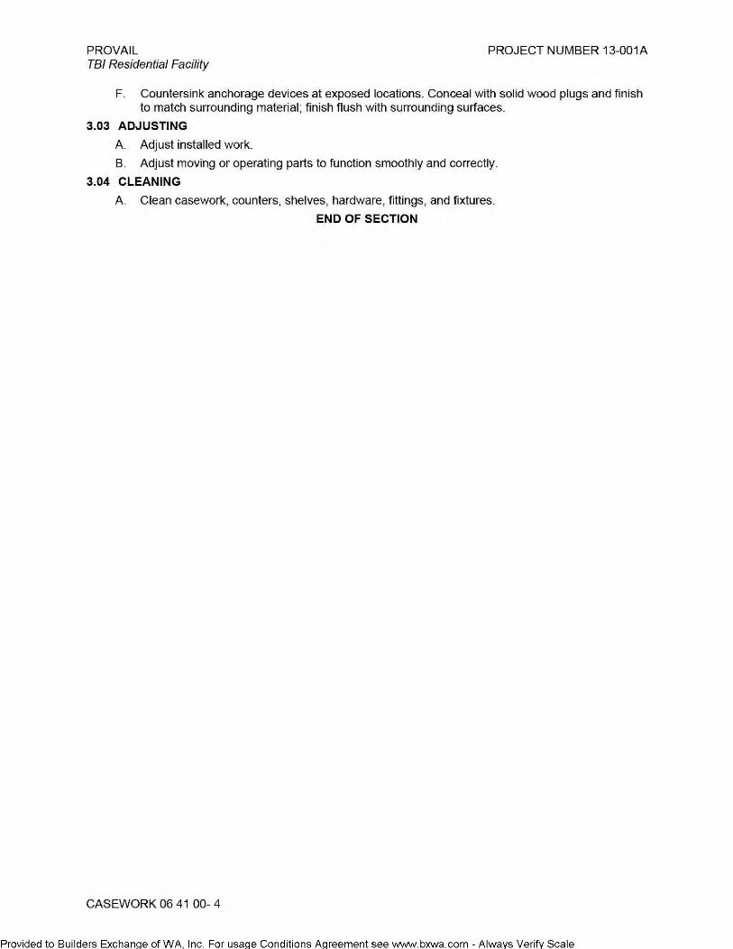
AREA1 ROOF AREA = 1987 sq ft
= 266126 sq in
TOTAL MIN ATTIC VENTING 1/300
REQUIRED = 954 sq in
REQUIRED AT RIDGE > 477 sq in MIN REQD 50%
RIDGE VENTING DESIGN = COR-A-VENT
NF A PER LINEAR FT = 17 sq in
LIN. FT. OF VENT PROVIDED = 37
TOTAL RIDGE VENTING 629 sq in= 0.66 %
REQUIRED AT EAVES = +-477 sq in
EAVE VENTING DESIGN = 2" DIA EAVE VENT HOLES
N.F.A PER VENT = 3.14 sq tn
#OF 24" BAYS = 21
#OF VENTS PER BAY = 5
#OF VENTS PROVIDED = 105
330 sq in= 0_34 %
TOTAL ATTIC VENTING PROVIDED = 959 sq in> 954
AREA2 ROOF AREA = 851 sq ft
= 122544 sq in
TOTAL MIN ATTIC VENTING 1/300
REQUIRED = 406 sq in
REQUIRED AT RIDGE > 204 sq in MIN REQD 50%
RIDGE VENTING DESIGN = COR-A-VENT
N.F.A PER LINEAR FT. = 17 sq in
LIN. FT. OF VENT PROVIDED = 13
TOTAL RIDGE VENTING 221 sq in= 0_50 %
REQUIRED AT EAVES = +-204 sq in
EAVE VENTING DESIGN = 2" DIA. EAVE VENT HOLES
N.F.A PER VENT = 3.14 sq in
#OF 24" BAYS = 14
#OF VENTS PER BAY = 5
#OF VENTS PROVIDED = 70
220 sq in= 0.50 %
TOTAL ATTIC VENTING PROVIDED = 441 sq in> 408
AREA3
ROOF AREA = 310sqft
= 44640 sq in
TOTAL MIN ATTIC VENTING 1/300
REQUIRED = 149 sq tn
REQUIRED AT HIGH EAVE > 74 sq in MIN REQD 50%
EAVE VENTING DESIGN = 2" DIA. EAVE VENT HOLES
N.F.A PER VENT = 3.14 sq in
#OF 24" BAYS = 9
#OF VENTS PER BAY = 3
#OF VENTS PROVIDED = 27
65 sq in= 0.50 %
REQUIRED AT LOW EAVES = +-74 sq in
EAVE VENTING DESIGN = 2" DIA. EAVE VENT HOLES
N.F.A PER VENT = 3.14 sq in
#OF 24" BAYS = 9
#OF VENTS PER BAY = 3
#OF VENTS PROVIDED = 27
85 sq in= 0.50 o/o
TOTAL ATTIC VENTING PROVIDED = 170 sq in> 149
AREA4
ROOF AREA = 456 sq ft
= 65664 sq in
TOTAL MIN ATTIC VENTING 1/300
REQUIRED = 219 sq in
REQUIRED AT RIDGE > 109 sq in MIN REQD 50%
RIDGE VENTING DESIGN = COR-A-VENT
N.F.A PER LINEAR FT. = 17 sq in
LIN. FT. OF VENT PROVIDED = 7
TOTAL RIDGE VENTING 119sqin= Q_51 O/o
REQUIRED AT EAVES = +-109 sq in
EAVE VENTING DESIGN = 2" DIA. EAVE VENT HOLES
N.F.A PER VENT = 3.14 sq in
#OF 24" BAYS = 16
#OF VENTS PER BAY = 2
#OF VENTS PROVIDED = 36
113sqin= 049%
TOTAL ATTIC VENTING PROVIDED = 232 sq in> 219
Provided to Builders Exchanae of WA Inc For usaae Conditions Aareement see wvlfvv.bxwa.com - Alwavs Verifv Scale
AREAS ROOF AREA
TOTAL MIN ATTIC VENTING
= =
REQUIRED =
REQUIRED AT RIDGE >
338 sq ft
46672 sq in
1/300
162 sq in
81 sq in MIN REQD 50%
AREA6
ROOF AREA
TOTAL MIN ATTIC VENTING
= =
REQUIRED =
REQUIRED AT RIDGE >
RIDGE VENTING DESIGN = COR-A-VENT
1791 sq ft
257904 sq in
1/300
660 sq in
430 sq in MIN REQD 50%
RIDGE VENTING DESIGN = COR-A-VENT NFA PER LINEAR FT =
LIN. FT. OF VENT PROVIDED =
17 sq in
33 N FA PER LI NEAR FT =
LIN. FT. OF VENT PROVIDED =
TOTAL RIDGE VENTING
REQUIRED AT EAVES
EAVE VENTING DESIGN N.F.A PER VENT
#OF 24" BAYS
#OF VENTS PER BAY
#OF VENTS PROVIDED
TOTAL ATTIC VENTING
=
= = = = =
17 sq in
9
153 sq in= 0.50 %
+-81 sq in
2" DIA EAVE VENT HOLES
3.14 sq tn
12
4
48
151 sq in= 0_50 °/o
/,,-----..._'-,
( B ) \I/ ' ' ' ' ' '
12'-10"
(G.1)~ ( 7~ ~ " ( ~ \~~v
' ' ' ' ' ' 45'-71 12"
/~,
\ D.1 ) 1/ 12'-0"
rE'1 \1/ ' ' ' ' ' '
TOTAL RIDGE VENTING
REQUIRED AT EAVES
EAVE VENTING DESIGN
NFAPERVENT
#OF 24" BAYS
#OF VENTS PER BAY
#OF VENTS PROVIDED
TOTAL ATTIC VENTING PROVIDED
=
=
= =
=
=
=
561 sq in= 0.64 %
+-430 sq in
2" DIA. EAVE VENT HOLES
314 sq in
20
5
100
314 sq in= 0_36 % ___ _J
875 sq in > 860
PROVI DE=D=------:::=:::------=-------3~0~4~s~q~in~>~16~2:__ ___ __J /~'
/ '
' ' ' ' ' ' ' ' ' ' ' ' ' '
: _J_ : I r--- \'----,,,_____,._ -------\,_--_____/;
/, ,..,.--~
I c.o \,__l---', - - - - - -
\'-..__/
="~r--.... 412 SLOPE I 4:12 SLOP~--~~,= -- - -- - - - - -- - -:- - -- - - - - -- - -- - -- - -- - -- - -- - -- - - - - -- - -- - -- - -- - -- - -- - -
Ii I i I : ------------------------------------------------------"~---~ -~ ------~-~--------;-~----4---------------------------------------------------~ ~ I // : I ~~~~VENT PER
~ : ~ I -~~~~ MECHANICAL, TYP.
/ - -, i ~ ~~~~~~I~~ ~ : I DJ ) -~~~~ ~ ~~~~ ---i-1-j-----------------~-(i-A4.:_ lj.1-,_\. '.v~
1' i
33'-0" I/ -;.)>"" ~/~- ! t I // ~~~AUST VENT, ~
..... JI .... : l \ J I ; .... ~ I // ill CONT. RIDGE vE.~T. 'rYPl -~ B : 1 ·····~ ··········r -- //
, ROOF AREA #6 ' j I : W //
: 1,791 S.F , g, 1 : : ~ /--~,//
-~ , : * . i :.; / r:t/ 1, I
(ID 11 i// I~~ : \ __ ./ I
\ -/0 I g; ~"'- i I
(~-1----'" ----__ , -----------------------------------------------------::-~T / r---.r~srnPF- /1 /i-4:12-siof>E_T~ "F::--- _ _j::-- --- --- --- --- --- -- --- ---:-- --- --- --- --- -~- --- --
¢> q ~ !,~I .~ l 'l • • • ~ '•JY ""JI I ·. ~ "' ; I I • • • ~·
I
1
1
ROOFAREAl#S I : : : w5 5
~ A41 v v
I
' ' 338 S.F: I : : : Ai1 I I I ' ' :
c: )--1----"------+----·~,- - -- - - - - -- - -- --~' -------------------~ "'---~~ ' 1 ·-J1~.~-y-_y_.: A _ _L/-)~~1 H-0-UR_S_M-OKE-~- -----------ii:~_ -- --- --- -- -r- ----'9 >... ./=-TI) ---, < ~ // BARRIER BELOW : :
'" I ~ ~" D • 1 v ~I < / ,,;// SEE DIA5.1 : I :
""'-, .· ,-::; / ' wl '
~- ROOFAREA#1 • '-·~.,•; Jj/1/ i g i ROOFAREA#3 I ~t ""°-i--------X-11 • 'I" ' "' ' 310 S.F o -1 1,987 S.F
'
#~'" ROO:::.~~:, I~ ii f 37'-0" f II .',!/fo~.\1 13'-0" t ~ .. ~ .. ~.~ .. ~ .. ~.=:!,. •••• t ~ 1'!!:; 2'0"TYP.
L/-+, 1 __ -+"--'--'+--+----+-------1-""-'"·-e- , 1 coNT R10GEVENT. TYP m ___ ,,, : :::>. m _ ...... _ _ ~ ~ T _ / ~ , " : ~ /f.I\~ ~ '9 ;.,_ _ l j ~ . : -;f----j,l>---------"'4----L'_j_,~-A-4 .1-1).1--"
'" '1: r1 3';0'I ROOF AREA #4:
(I I - - . -,--- 9 '\ I \ I ~ I 456 S.F i ;;;
I"' ANCHOR TYP SEE DETAIL /]'- ' yp \ ~ L : I ~I 10/A72VERIFYQTYAND / I ~ : ·-~· II - -- - - - -- ~~- - - - :___jC-------"-
·············· ·· l. r I ~~:w:;7,/ u:• "~~ "-.~ t "°":.~.. lj .. ~:::::::::::: .::!~::.. =~ . . .. / ,,,----"-.,,
I N \,__L---'L, - - - - -',
I / 4:12 SLOPE I 412 SLOP~ ~ II ,, : :
(~-_)-"---"- -----+----------'=_=_=_=_=_=_:-ff"··~········· ................ J ___ ·- --- _J~ _Fi='*=_~"'' _=\~\=\±:":;:_=_=_=_=_=_= __ =_=_=_=_=_=_= __ =_=_=_=_= __ =_=_11:':::1_ -- ------ --- ------ --
~ UTIER. TYP.
' ' ' ' ' ' ' ' ' ' ' ' ' ' - -- - --1- -- - -- - -- - -- - -- - t---------
' ' ' ' ' '
( i~+-----(:-2~t> ~ "~
' \ f. I A I \._ ,/
30' 5" -
35'-8"
~
\
( C I \ I '-._/
19' 6 - 112"
' \ : \.LINE OF BLDG.
( ""' ' BELOW, TYP.
7 >: \ ,_A4.1 : v :
'
' 17'-3"
96'-81 /2"
/~"'.
'
,,--I \ ( E I \._/
'
~
I '-
I F 1
'-._)
' 10'-91/2" '
/ ' ( G ) \______/
AREA 7
ROOF AREA =
=
TOTAL MIN ATTIC VENTING REQUIRED =
REQUIRED AT RIDGE >
RIDGE VENTING DESIGN =
NF A PER LINEAR FT =
LIN. FT. OF VENT PROVIDED =
TOTAL RIDGE VENTING
REQUIRED AT EAVES =
EAVE VENTING DESIGN =
NFA PER VENT =
#OF 24" BAYS =
#OF VENTS PER BAY =
#OF VENTS PROVIDED =
TOTAL ATTIC VENTING PROVIDED =
94 sq ft
13536 sq tn
1/300
45 sq in
23 sq in MIN REQD 50%
COR-A-VENT
17 sq in
3
51 sq in = 0.50 %
+-23 sq in
2" DIA. EA VE VENT HOLES
3 14 sq in
4
4
16
50 sq in = 0_50 Ofa
101sqin> 45
environmental WORKS
Community Design Center
402 15th Avenue East Seattle, Washington 98112
206.329.8300 206.329.5494 fax
PROVAIL Traumatic Brain Injury
Residential Facility 1548 NE 175th Street Shoreline, WA 98155
Roof Plan
Dale
2 June 2014 Bid Set Revisions
Permit Set: 31 January 2014
A ~er~~1;~i~ -~~~ -2-~~~; ;~;~ -----------------
_____ ___ __________ Drawn _by:
cc ___ _________ Chec_keci _by_ (PcMJ:
DB ____________ Chec_keci _b.Y_lQ.CJ:
DB ________________ _Prole_ct Noc
13-001A
A2.2 •• ••