Embed Size (px)
Citation preview
1©2014 Raj Jainhttp://www.cse.wustl.edu/~jain/tutorials/nv_sc14.htmWashington University in St. Louis
Protocols for Protocols for Data Center Network Data Center Network
Virtualization and Cloud ComputingVirtualization and Cloud Computing
Washington University in Saint Louis
Saint Louis, MO 63130
Tutorial at ACM SIGCOMM 2014, Chicago, IL
August 22, 2014
These slides and a video recording of this tutorial are at:http://www.cse.wustl.edu/~jain/tutorials/nv_sc14.htm
2©2014 Raj Jainhttp://www.cse.wustl.edu/~jain/tutorials/nv_sc14.htmWashington University in St. Louis
OverviewOverview
1.
Part I: Network Virtualization
2.
Part II: Data Center Bridging3.
Part III: Carrier Ethernet for Data Centers Break
4.
Part IV: Virtual Bridging5.
Part V: LAN Extension and Partitioning

3©2014 Raj Jainhttp://www.cse.wustl.edu/~jain/tutorials/nv_sc14.htmWashington University in St. Louis
Part I: Network VirtualizationPart I: Network Virtualization
1.
Virtualization2.
Why Virtualize?3.
Network Virtualization4.
Names, IDs, Locators
5.
Interconnection Devices
4©2014 Raj Jainhttp://www.cse.wustl.edu/~jain/tutorials/nv_sc14.htmWashington University in St. Louis
Part II: Data Center BridgingPart II: Data Center Bridging
1.
Residential vs. Data Center Ethernet2.
Review of Ethernet devices and algorithms
3.
Enhancements to Spanning Tree Protocol4.
Virtual LANs
5.
Data Center Bridging Extensions

5©2014 Raj Jainhttp://www.cse.wustl.edu/~jain/tutorials/nv_sc14.htmWashington University in St. Louis
Part III: Carrier Ethernet for Data CentersPart III: Carrier Ethernet for Data Centers
1.
Provider Bridges (PB) or Q-in-Q2.
Provider Backbone Bridges (PBB) or MAC-in-MAC3.
Provider Backbone Bridges with Traffic Engineering (PBB- TE)
Note: Although these technologies were originally developed for carriers, they are now used inside multi-tenant
data centers
(clouds)

6©2014 Raj Jainhttp://www.cse.wustl.edu/~jain/tutorials/nv_sc14.htmWashington University in St. Louis
Part IV: Virtual BridgingPart IV: Virtual Bridging
1.
Virtual Bridges to connect virtual machines2.
IEEE Virtual Edge Bridging Standard 3.
Single Root I/O Virtualization (SR-IOV)4.
Aggregating Bridges and Links: VSS and vPC5.
Bridges with massive number of ports: VBE
7©2014 Raj Jainhttp://www.cse.wustl.edu/~jain/tutorials/nv_sc14.htmWashington University in St. Louis
Part V: LAN Extension and PartitioningPart V: LAN Extension and Partitioning
1.
Transparent Interconnection of Lots of Links (TRILL)
2.
Network Virtualization using GRE (NVGRE)3.
Virtual eXtensible
LANs (VXLAN)4.
Stateless Transport Tunneling Protocol (STT)
8©2014 Raj Jainhttp://www.cse.wustl.edu/~jain/tutorials/nv_sc14.htmWashington University in St. Louis
Part I: Network VirtualizationPart I: Network Virtualization
1.
Virtualization2.
Why Virtualize?3.
Network Virtualization4.
Names, IDs, Locators
5.
Interconnection Devices
9©2014 Raj Jainhttp://www.cse.wustl.edu/~jain/tutorials/nv_sc14.htmWashington University in St. Louis
VirtualizationVirtualization“Virtualization means that Applications can use a resource
without any concern for where it resides, what the technical interface is, how it has been implemented, which platform it uses, and how much of it is available.”
-Rick F. Van der
Lans in Data Virtualization for Business Intelligence Systems
10©2014 Raj Jainhttp://www.cse.wustl.edu/~jain/tutorials/nv_sc14.htmWashington University in St. Louis
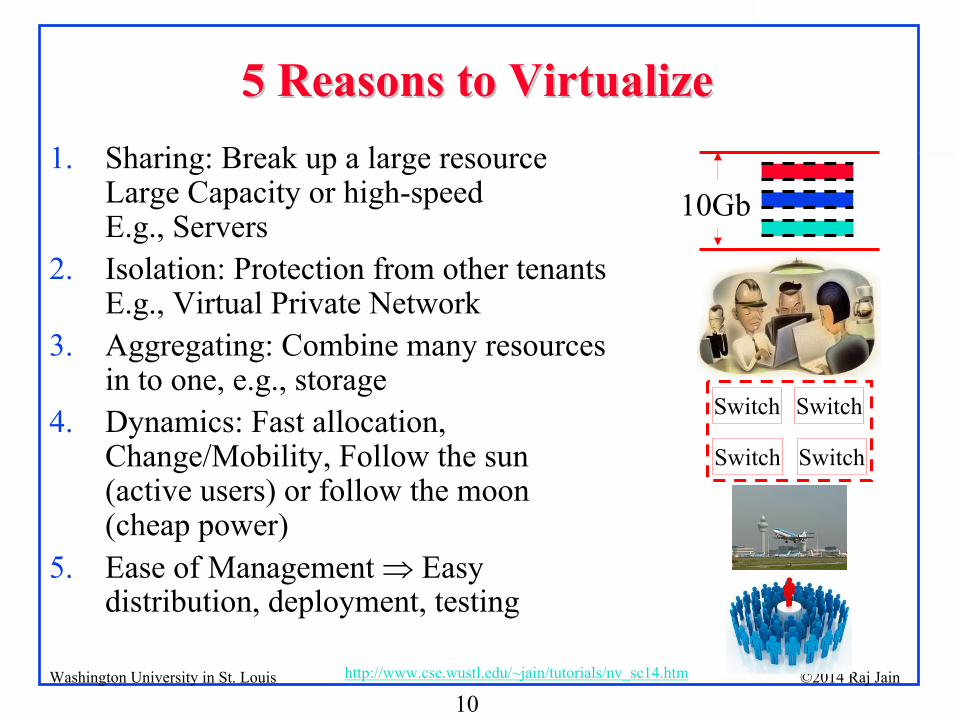
5 Reasons to Virtualize5 Reasons to Virtualize1.
Sharing: Break up a large resource
Large Capacity or high-speed E.g., Servers
2.
Isolation: Protection from other tenants E.g., Virtual Private Network
3.
Aggregating: Combine many resources in to one, e.g., storage
4.
Dynamics: Fast allocation, Change/Mobility, Follow the sun (active users) or follow the moon (cheap power)
5.
Ease of Management Easy distribution, deployment, testing
SwitchSwitch
Switch Switch
10Gb
11©2014 Raj Jainhttp://www.cse.wustl.edu/~jain/tutorials/nv_sc14.htmWashington University in St. Louis
Virtualization in ComputingVirtualization in Computing
Storage:
Virtual Memory L1, L2, L3, ... Recursive
Virtual CDs, Virtual Disks (RAID), Cloud storage
Computing:
Virtual Desktop Virtual Server Virtual DatacenterThin Client
VMs
Cloud
Networking: Plumbing of computing
Virtual Channels, Virtual LANs, Virtual Private Networks
12©2014 Raj Jainhttp://www.cse.wustl.edu/~jain/tutorials/nv_sc14.htmWashington University in St. Louis
Network VirtualizationNetwork Virtualization1.
Network virtualization allows tenants to form an overlay network
in a multi-tenant network such that tenant can control:1.
Connectivity layer: Tenant network can be L2 while the provider is L3 and vice versa
2.
Addresses: MAC addresses and IP addresses3.
Network Partitions: VLANs and Subnets4.
Node Location: Move nodes freely2.
Network virtualization allows providers to serve a large number of tenants without worrying about:1.
Internal addresses used in client networks2.
Number of client nodes3.
Location of individual client nodes4.
Number and values of client partitions (VLANs and Subnets)3.
Network could be a single physical interface, a single physical machine, a data center, a metro, …
or the global Internet.
4.
Provider could be a system owner, an enterprise, a cloud provider, or a carrier.
13©2014 Raj Jainhttp://www.cse.wustl.edu/~jain/tutorials/nv_sc14.htmWashington University in St. Louis
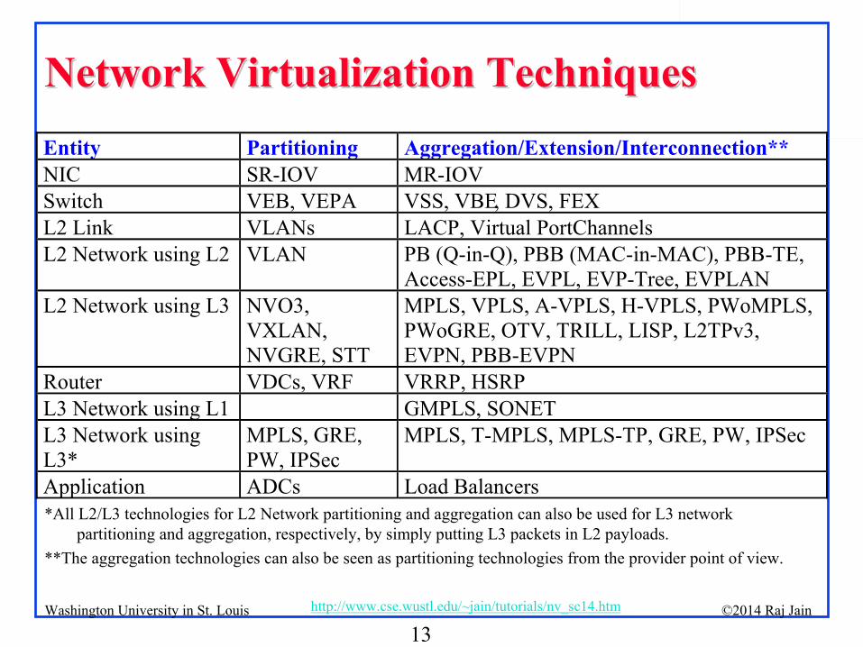
Network Virtualization TechniquesNetwork Virtualization Techniques
*All L2/L3 technologies for L2 Network partitioning and aggregation can also be used for L3 network partitioning and aggregation, respectively, by simply putting L3
packets in L2 payloads.**The aggregation technologies can also be seen as partitioning technologies from the provider point of view.
Entity Partitioning Aggregation/Extension/Interconnection**NIC SR-IOV MR-IOVSwitch VEB, VEPA VSS, VBE, DVS, FEXL2 Link VLANs LACP, Virtual PortChannelsL2 Network using L2 VLAN PB (Q-in-Q), PBB (MAC-in-MAC), PBB-TE,
Access-EPL, EVPL, EVP-Tree, EVPLANL2 Network using L3 NVO3,
VXLAN, NVGRE, STT
MPLS, VPLS, A-VPLS, H-VPLS, PWoMPLS, PWoGRE, OTV, TRILL, LISP, L2TPv3, EVPN, PBB-EVPN
Router VDCs, VRF VRRP, HSRPL3 Network using L1 GMPLS, SONETL3 Network using L3*
MPLS, GRE, PW, IPSec
MPLS, T-MPLS, MPLS-TP, GRE, PW, IPSec
Application ADCs Load Balancers
14©2014 Raj Jainhttp://www.cse.wustl.edu/~jain/tutorials/nv_sc14.htmWashington University in St. Louis
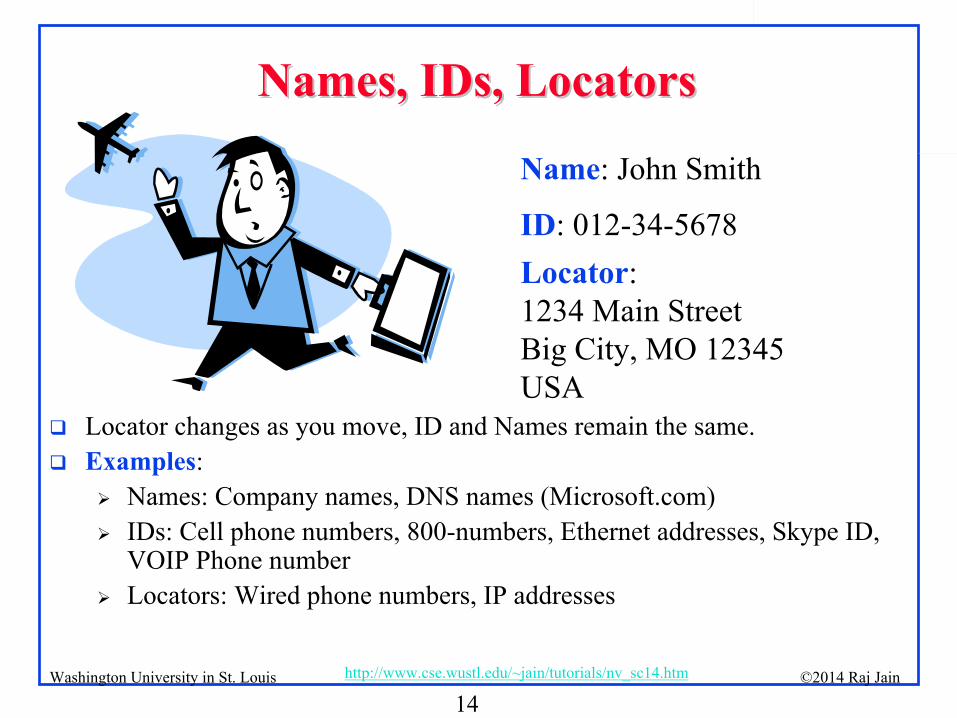
Names, IDs, LocatorsNames, IDs, Locators
Locator changes as you move, ID and Names remain the same.
Examples:
Names: Company names, DNS names (Microsoft.com)
IDs: Cell phone numbers, 800-numbers, Ethernet addresses, Skype ID, VOIP Phone number
Locators: Wired phone numbers, IP addresses
Name: John Smith
ID: 012-34-5678Locator:
1234 Main StreetBig City, MO 12345
USA
15©2014 Raj Jainhttp://www.cse.wustl.edu/~jain/tutorials/nv_sc14.htmWashington University in St. Louis
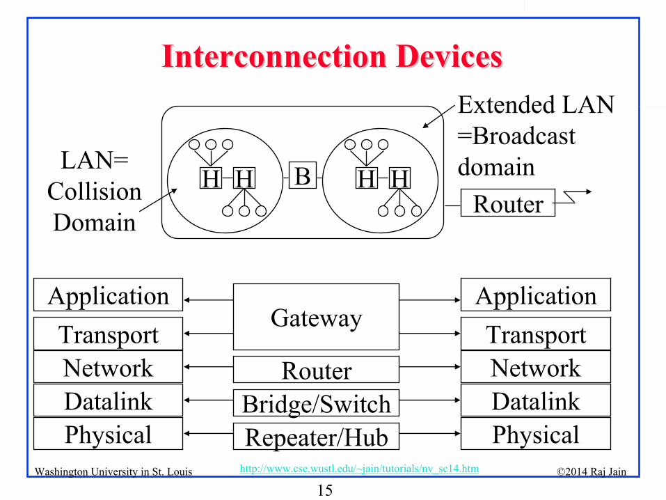
Interconnection DevicesInterconnection Devices
H H B H HRouter
Extended LAN=Broadcast domainLAN=
Collision Domain
NetworkDatalinkPhysical
TransportRouter
Bridge/SwitchRepeater/Hub
GatewayApplication
NetworkDatalinkPhysical
TransportApplication
16©2014 Raj Jainhttp://www.cse.wustl.edu/~jain/tutorials/nv_sc14.htmWashington University in St. Louis
Interconnection Devices (Cont)Interconnection Devices (Cont)
Repeater: PHY device that restores data and collision signals
Hub: Multiport repeater + fault detection and recovery
Bridge: Datalink layer device connecting two or more collision domains. MAC multicasts are propagated throughout “extended LAN.”
Router: Network layer device. IP, IPX, AppleTalk. Does not propagate MAC multicasts.
Switch: Multiport bridge with parallel paths
These are functions. Packaging varies.
No CSMA/CD in 10G and up
No CSMA/CD in practice now even at home or at 10 Mbps
17©2014 Raj Jainhttp://www.cse.wustl.edu/~jain/tutorials/nv_sc14.htmWashington University in St. Louis
Fallacies Taught in Networking ClassesFallacies Taught in Networking Classes
1.
Ethernet is a local area network (Local <
2km)2.
Token ring, Token Bus, and CSMA/CD are the three most common LAN access methods.
3.
Ethernet uses CSMA/CD.4.
Ethernet bridges use spanning tree for packet forwarding.5.
Ethernet frames are limited to 1518 bytes.6.
Ethernet does not provide any delay guarantees.7.
Ethernet has no congestion control.8.
Ethernet has strict priorities.
Ethernet has changed. All of these are now false or are becoming false.
18©2014 Raj Jainhttp://www.cse.wustl.edu/~jain/tutorials/nv_sc14.htmWashington University in St. Louis
Summary of Part ISummary of Part I
1.
Virtualization allows applications to use resources without worrying about its location, size, format etc.
2.
Ethernet’s use of IDs as addresses makes it very easy to move systems in the data center Keep traffic on the same Ethernet
3.
Cloud computing requires Ethernet to be extended globally and partitioned for sharing by a very large number of customers who have complete control over their address assignment and connectivity
4.
Many of the previous limitations of Ethernet have been overcome in the last few years.
19©2014 Raj Jainhttp://www.cse.wustl.edu/~jain/tutorials/nv_sc14.htmWashington University in St. Louis
Levels of Network VirtualizationLevels of Network Virtualization
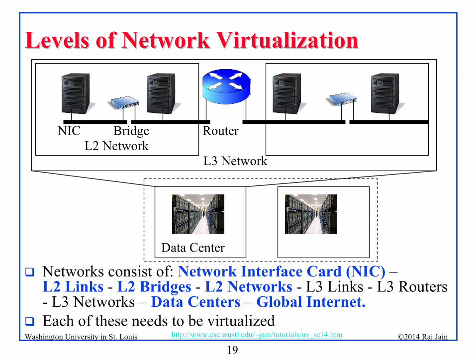
NIC Bridge Router
L3 NetworkL2 Network
Data Center
Networks consist of: Network Interface Card (NIC)
– L2 Links
-
L2 Bridges
-
L2 Networks
-
L3 Links -
L3 Routers
-
L3 Networks –
Data Centers
–
Global Internet.
Each of these needs to be virtualized

20©2014 Raj Jainhttp://www.cse.wustl.edu/~jain/tutorials/nv_sc14.htmWashington University in St. Louis
Part II: Data Center BridgingPart II: Data Center Bridging
1.
Residential vs. Data Center Ethernet2.
Review of Ethernet devices and algorithms
3.
Enhancements to Spanning Tree Protocol4.
Virtual LANs
5.
Data Center Bridging Extensions
21©2014 Raj Jainhttp://www.cse.wustl.edu/~jain/tutorials/nv_sc14.htmWashington University in St. Louis
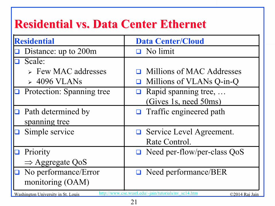
Residential vs. Data Center EthernetResidential vs. Data Center EthernetResidential
Distance: up to 200m
Scale:
Few MAC addresses
4096 VLANs
Protection: Spanning tree
Path determined by spanning tree
Simple service
Priority Aggregate QoS
No performance/Error monitoring (OAM)
Data Center/Cloud
No limit
Millions of MAC Addresses
Millions of VLANs Q-in-Q
Rapid spanning tree, … (Gives 1s, need 50ms)
Traffic engineered path
Service Level Agreement. Rate Control.
Need per-flow/per-class QoS
Need performance/BER
22©2014 Raj Jainhttp://www.cse.wustl.edu/~jain/tutorials/nv_sc14.htmWashington University in St. Louis
Spanning Tree and its EnhancementsSpanning Tree and its Enhancements
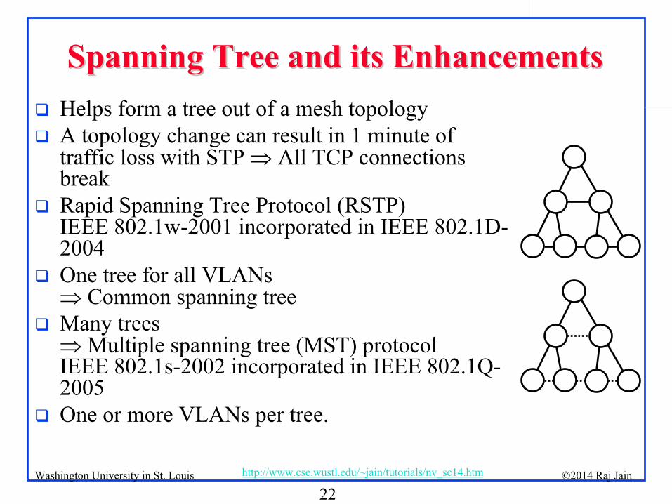
Helps form a tree out of a mesh topology
A topology change can result in 1 minute of traffic loss with STP All TCP connections break
Rapid Spanning Tree Protocol (RSTP) IEEE 802.1w-2001 incorporated in IEEE 802.1D-
2004
One tree for all VLANs Common spanning tree
Many trees Multiple spanning tree (MST) protocol IEEE 802.1s-2002 incorporated in IEEE 802.1Q-
2005
One or more VLANs per tree.
23©2014 Raj Jainhttp://www.cse.wustl.edu/~jain/tutorials/nv_sc14.htmWashington University in St. Louis
ISIS--IS ProtocolIS Protocol
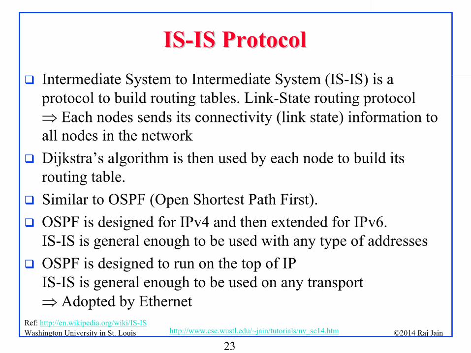
Intermediate System to Intermediate System (IS-IS) is a protocol to build routing tables. Link-State routing protocol Each nodes sends its connectivity (link state) information to all nodes in the network
Dijkstra’s
algorithm is then used by each node to build its routing table.
Similar to OSPF (Open Shortest Path First).
OSPF is designed for IPv4 and then extended for IPv6. IS-IS is general enough to be used with any type of addresses
OSPF is designed to run on the top of IP IS-IS is general enough to be used on any transport
Adopted by EthernetRef: http://en.wikipedia.org/wiki/IS-IS
24©2014 Raj Jainhttp://www.cse.wustl.edu/~jain/tutorials/nv_sc14.htmWashington University in St. Louis
Shortest Path BridgingShortest Path Bridging
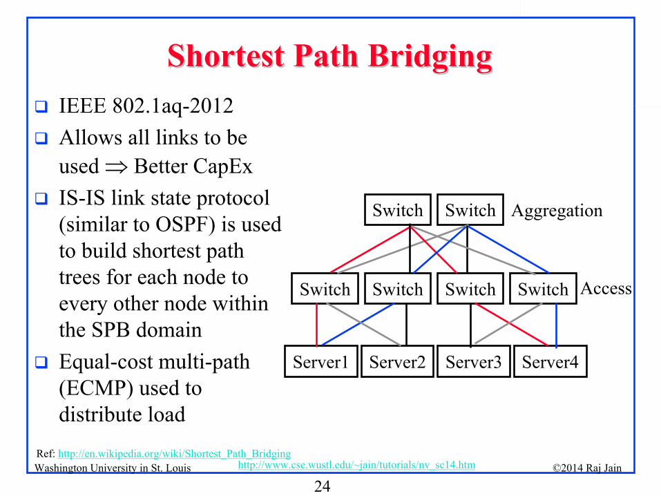
IEEE 802.1aq-2012
Allows all links to be used Better CapEx
IS-IS link state protocol (similar to OSPF) is used to build shortest path trees for each node to every other node within the SPB domain
Equal-cost multi-path (ECMP) used to distribute load
Ref: http://en.wikipedia.org/wiki/Shortest_Path_Bridging
Access
Aggregation
Server2 Server3 Server4Server1
Switch Switch SwitchSwitch
Switch Switch
25©2014 Raj Jainhttp://www.cse.wustl.edu/~jain/tutorials/nv_sc14.htmWashington University in St. Louis
What is a LAN?What is a LAN?
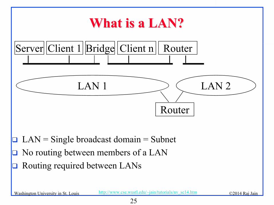
LAN = Single broadcast domain = Subnet
No routing between members of a LAN
Routing required between LANs
RouterClient nClient 1Server
LAN 1 LAN 2
Router
Bridge
26©2014 Raj Jainhttp://www.cse.wustl.edu/~jain/tutorials/nv_sc14.htmWashington University in St. Louis
Virtual LANVirtual LAN
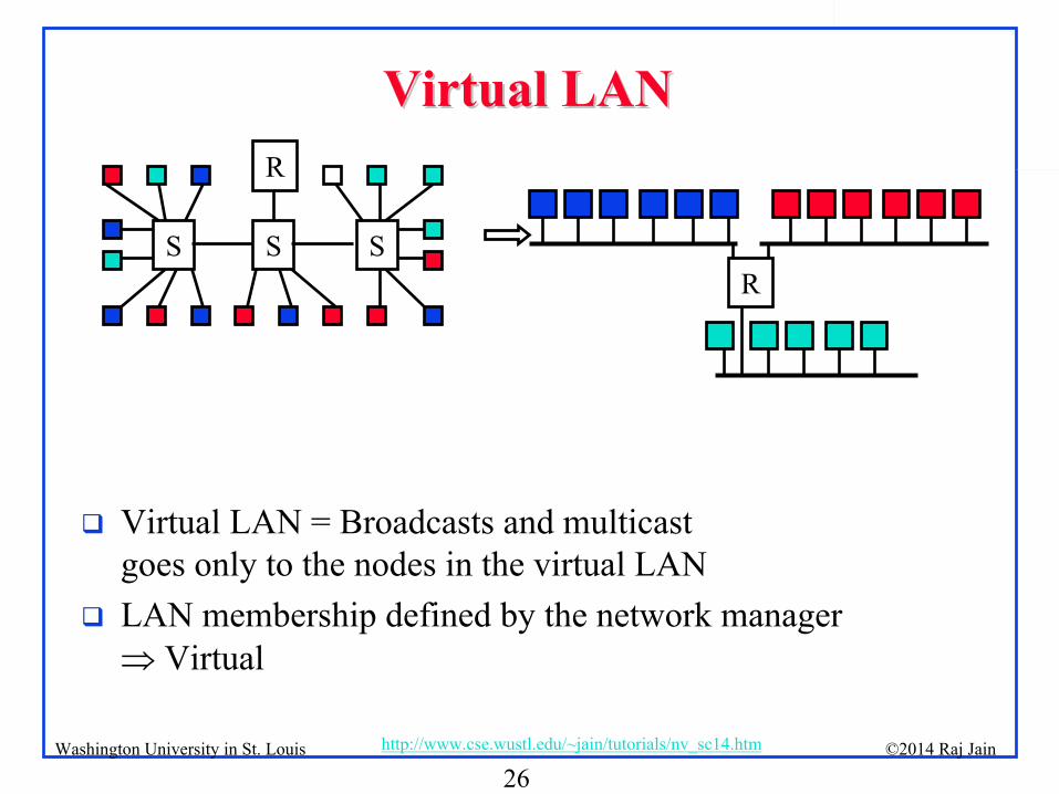
Virtual LAN = Broadcasts and multicast goes only to the nodes in the virtual LAN
LAN membership defined by the network manager Virtual
S S S
R
R
27©2014 Raj Jainhttp://www.cse.wustl.edu/~jain/tutorials/nv_sc14.htmWashington University in St. Louis
IEEE 802.1QIEEE 802.1Q--2011 Tag2011 Tag
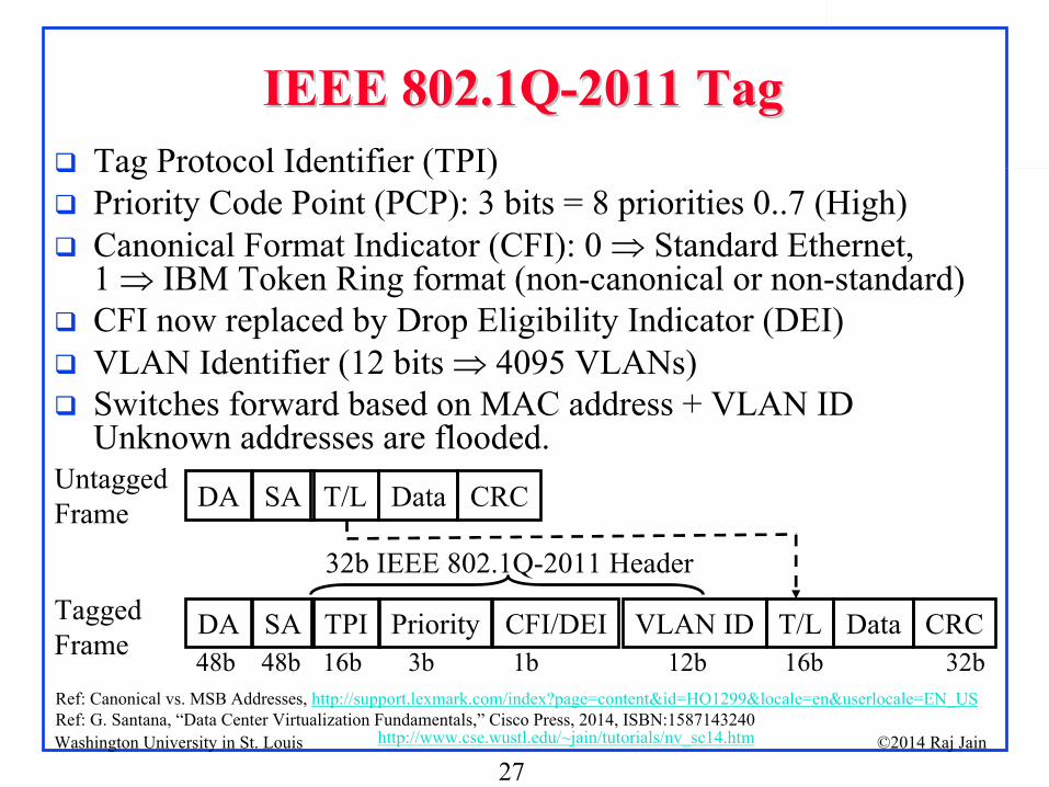
Tag Protocol Identifier (TPI)
Priority Code Point (PCP): 3 bits = 8 priorities 0..7 (High)
Canonical Format Indicator (CFI): 0 Standard Ethernet, 1 IBM Token Ring format (non-canonical or non-standard)
CFI now replaced by Drop Eligibility Indicator (DEI)
VLAN Identifier (12 bits 4095 VLANs)
Switches forward based on MAC address + VLAN ID Unknown addresses are flooded.
Ref: Canonical vs. MSB Addresses, http://support.lexmark.com/index?page=content&id=HO1299&locale=en&userlocale=EN_US
Ref: G. Santana, “Data Center Virtualization Fundamentals,”
Cisco Press, 2014, ISBN:1587143240
DA SA TPI Priority T/LCFI/DEI VLAN ID Data CRC
DA SA T/L Data CRC
32b IEEE 802.1Q-2011 Header
16b 3b 1b 12b 16b 32b48b48b
Untagged Frame
Tagged Frame
28©2014 Raj Jainhttp://www.cse.wustl.edu/~jain/tutorials/nv_sc14.htmWashington University in St. Louis
Data Center Bridging (DCB)Data Center Bridging (DCB)
Goal: To enable storage traffic over Ethernet
Four Standards:
Priority-based Flow Control (IEEE 802.1Qbb-2011)
Enhanced Transmission Selection (IEEE 802.1Qaz-2011)
Congestion Control (IEEE 802.1Qau-2010)
Data Center Bridging Exchange (IEEE 802.1Qaz-2011)
Ref: M. Hagen, “Data Center Bridging Tutorial,”
http://www.iol.unh.edu/services/testing/dcb/training/DCB-Tutorial.pdf
29©2014 Raj Jainhttp://www.cse.wustl.edu/~jain/tutorials/nv_sc14.htmWashington University in St. Louis
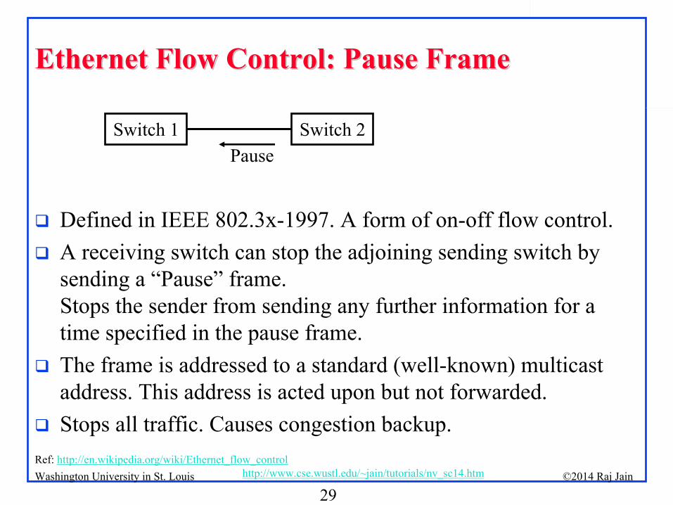
Ethernet Flow Control: Pause FrameEthernet Flow Control: Pause Frame
Defined in IEEE 802.3x-1997. A form of on-off flow control.
A receiving switch can stop the adjoining sending switch by sending a “Pause”
frame.
Stops the sender from sending any further information for a time specified in the pause frame.
The frame is addressed to a standard (well-known) multicast address. This address is acted upon but not forwarded.
Stops all traffic. Causes congestion backup.
Switch 1 Switch 2Pause
Ref: http://en.wikipedia.org/wiki/Ethernet_flow_control
30©2014 Raj Jainhttp://www.cse.wustl.edu/~jain/tutorials/nv_sc14.htmWashington University in St. Louis
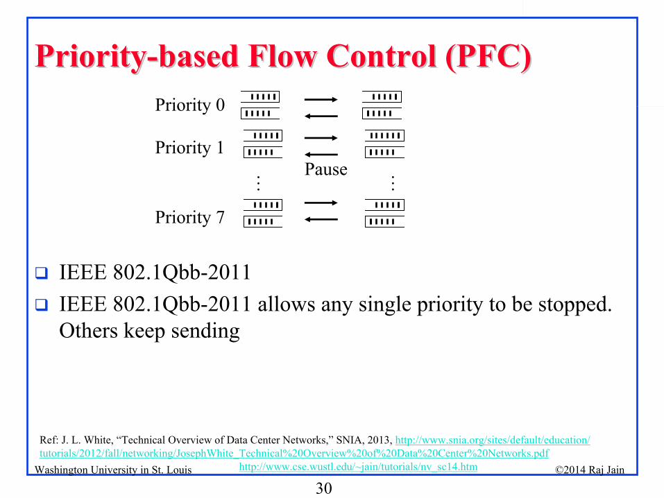
PriorityPriority--based Flow Control (PFC)based Flow Control (PFC)
IEEE 802.1Qbb-2011
IEEE 802.1Qbb-2011 allows any single priority to be stopped. Others keep sending
Ref: J. L. White, “Technical Overview of Data Center Networks,”
SNIA, 2013, http://www.snia.org/sites/default/education/
tutorials/2012/fall/networking/JosephWhite_Technical%20Overview%20of%20Data%20Center%20Networks.pdf
Priority 0
Priority 1
Priority 7
Pause
… …
31©2014 Raj Jainhttp://www.cse.wustl.edu/~jain/tutorials/nv_sc14.htmWashington University in St. Louis
Enhanced Transmission SelectionEnhanced Transmission Selection
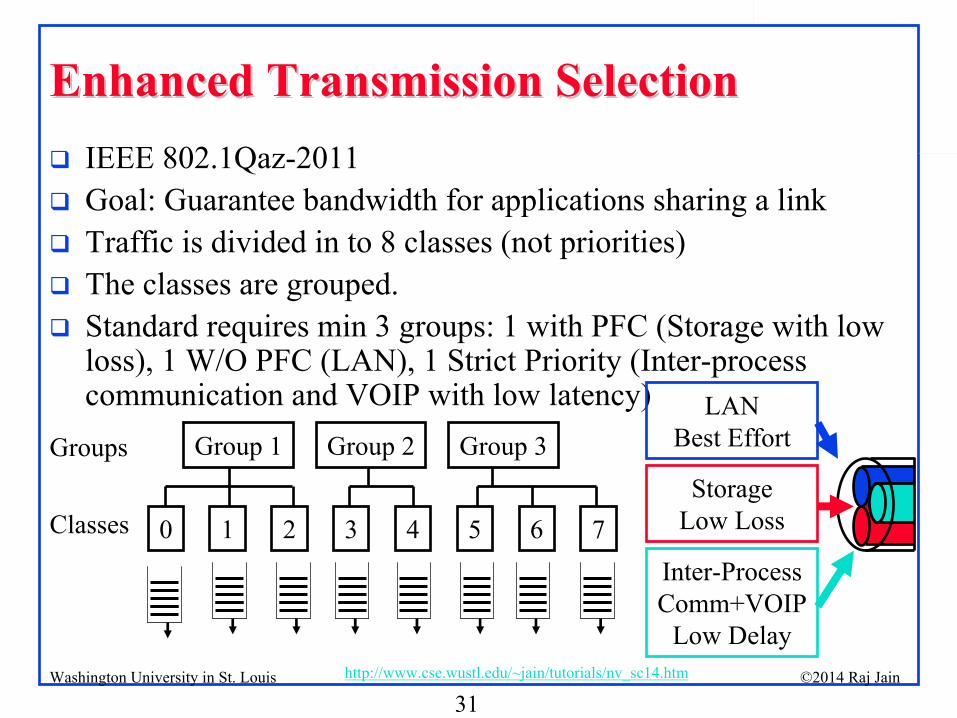
IEEE 802.1Qaz-2011
Goal: Guarantee bandwidth for applications sharing a link
Traffic is divided in to 8 classes (not priorities)
The classes are grouped.
Standard requires min 3 groups: 1 with PFC (Storage with low loss), 1 W/O PFC (LAN), 1 Strict Priority (Inter-process communication and VOIP with low latency)
0 1 2 3 4 5 6 7
Group 1 Group 2 Group 3
Classes
GroupsLAN
Best Effort
Storage
Low Loss
Inter-Process
Comm+VOIP
Low Delay
32©2014 Raj Jainhttp://www.cse.wustl.edu/~jain/tutorials/nv_sc14.htmWashington University in St. Louis
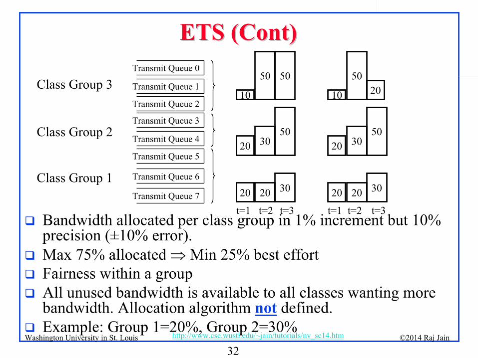
ETS (Cont)ETS (Cont)
Bandwidth allocated per class group in 1% increment but 10% precision (±10% error).
Max 75% allocated Min 25% best effort
Fairness within a group
All unused bandwidth is available to all classes wanting more bandwidth. Allocation algorithm not
defined.
Example: Group 1=20%, Group 2=30%
Class Group 3Transmit Queue 0
Transmit Queue 1
Transmit Queue 2
Transmit Queue 3
Transmit Queue 4
Transmit Queue 5
Transmit Queue 6
Transmit Queue 7 20
20
10
20
30
50
30
50
50
20
20
10
20
30
50
30
50
t=1 t=2 t=3 t=1 t=2 t=3
Class Group 2
Class Group 1
20
33©2014 Raj Jainhttp://www.cse.wustl.edu/~jain/tutorials/nv_sc14.htmWashington University in St. Louis
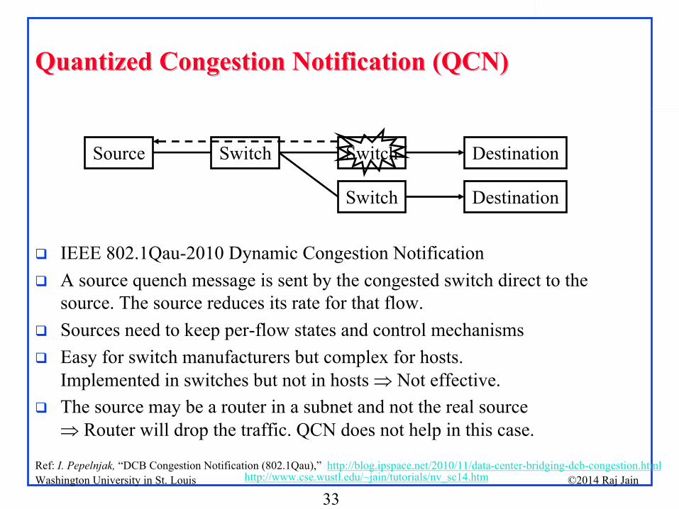
Quantized Congestion Notification (QCN)Quantized Congestion Notification (QCN)
IEEE 802.1Qau-2010 Dynamic Congestion Notification
A source quench message is sent by the congested switch direct to the source. The source reduces its rate for that flow.
Sources need to keep per-flow states and control mechanisms
Easy for switch manufacturers but complex for hosts. Implemented in switches but not in hosts Not effective.
The source may be a router in a subnet and not the real source
Router will drop the traffic. QCN does not help in this case.
DestinationSwitch
Source DestinationSwitch Switch
Ref: I. Pepelnjak,
“DCB Congestion Notification (802.1Qau),”
http://blog.ipspace.net/2010/11/data-center-bridging-dcb-congestion.html
34©2014 Raj Jainhttp://www.cse.wustl.edu/~jain/tutorials/nv_sc14.htmWashington University in St. Louis
DCBXDCBX
Data Center Bridging eXchange, IEEE 802.1Qaz-2011
Uses LLDP (Link Level Discovery Protocol) to negotiate quality metrics and capabilities for Priority-based Flow Control, Enhanced Transmission Selection, and Quantized Congestion Notification
New TLV’s
Priority group definition
Group bandwidth allocation
PFC enablement per priority
QCN enablement
DCB protocol profiles
FCoE and iSCSI profiles
35©2014 Raj Jainhttp://www.cse.wustl.edu/~jain/tutorials/nv_sc14.htmWashington University in St. Louis
Summary of Part IISummary of Part II
1.
Ethernet’s use of IDs as addresses makes it very easy to move systems in the data center Keep traffic on the same Ethernet
2.
Spanning tree is wasteful of resources and slow. Ethernet now uses shortest path bridging (similar to OSPF)
3.
VLANs allow different non-trusting entities to share an Ethernet network
4.
Data center bridging extensions reduce the packet loss by enhanced transmission selection and Priority-based flow control
36©2014 Raj Jainhttp://www.cse.wustl.edu/~jain/tutorials/nv_sc14.htmWashington University in St. Louis
Part III: Carrier Ethernet for Data CentersPart III: Carrier Ethernet for Data Centers
1.
Provider Bridges (PB) or Q-in-Q2.
Provider Backbone Bridges (PBB) or MAC-in-MAC3.
Provider Backbone Bridges with Traffic Engineering (PBB- TE)
Note: Although these technologies were originally developed for carriers, they are now used inside multi-tenant
data centers
(clouds)
37©2014 Raj Jainhttp://www.cse.wustl.edu/~jain/tutorials/nv_sc14.htmWashington University in St. Louis
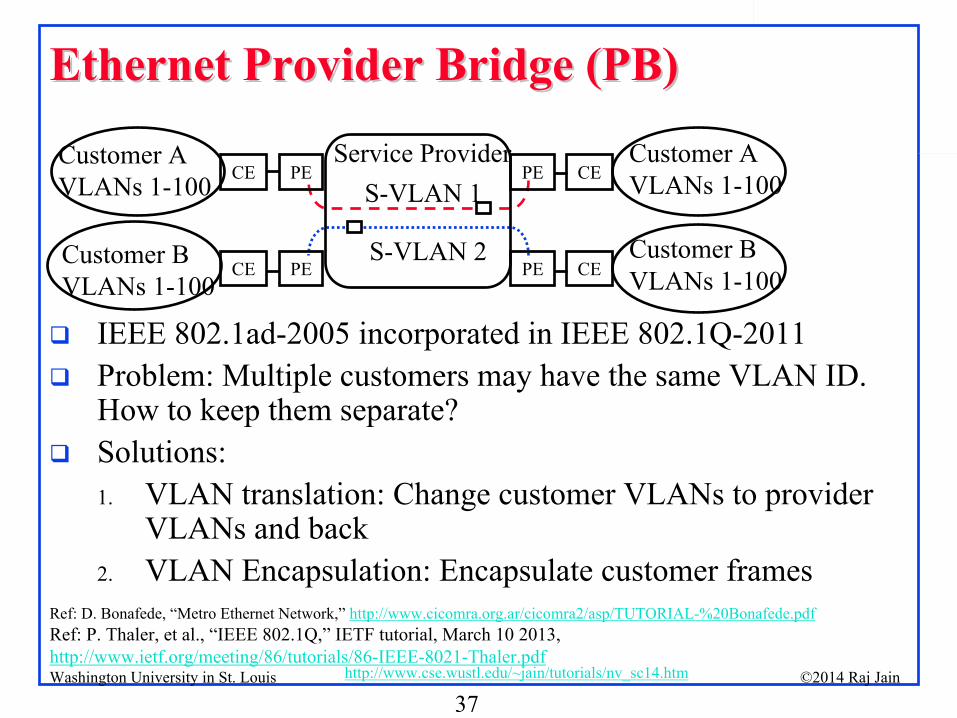
Ethernet Provider Bridge (PB)Ethernet Provider Bridge (PB)
IEEE 802.1ad-2005 incorporated in IEEE 802.1Q-2011
Problem: Multiple customers may have the same VLAN ID. How to keep them separate?
Solutions: 1.
VLAN translation: Change customer VLANs to provider VLANs and back
2.
VLAN Encapsulation: Encapsulate customer frames
Service ProviderCustomer AVLANs 1-100
Customer BVLANs 1-100
Customer BVLANs 1-100
Customer AVLANs 1-100
S-VLAN 2
S-VLAN 1
CEPE
PE CE
PECE
CE PE
Ref: D. Bonafede, “Metro Ethernet Network,”
http://www.cicomra.org.ar/cicomra2/asp/TUTORIAL-%20Bonafede.pdfRef: P. Thaler, et al., “IEEE 802.1Q,”
IETF tutorial, March 10 2013, http://www.ietf.org/meeting/86/tutorials/86-IEEE-8021-Thaler.pdf
38©2014 Raj Jainhttp://www.cse.wustl.edu/~jain/tutorials/nv_sc14.htmWashington University in St. Louis
Provider Bridge (Cont)Provider Bridge (Cont)
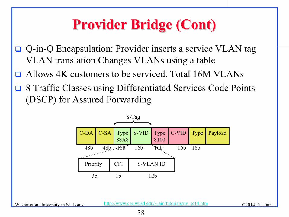
Q-in-Q Encapsulation: Provider inserts a service VLAN tag VLAN translation Changes VLANs using a table
Allows 4K customers to be serviced. Total 16M VLANs
8 Traffic Classes using Differentiated Services Code Points (DSCP) for Assured Forwarding
Priority CFI S-VLAN ID
S-Tag
3b 1b 12b
Type88A8
Type8100
C-DA C-SA S-VID C-VID Type Payload
48b 48b 16b 16b 16b 16b 16b
39©2014 Raj Jainhttp://www.cse.wustl.edu/~jain/tutorials/nv_sc14.htmWashington University in St. Louis
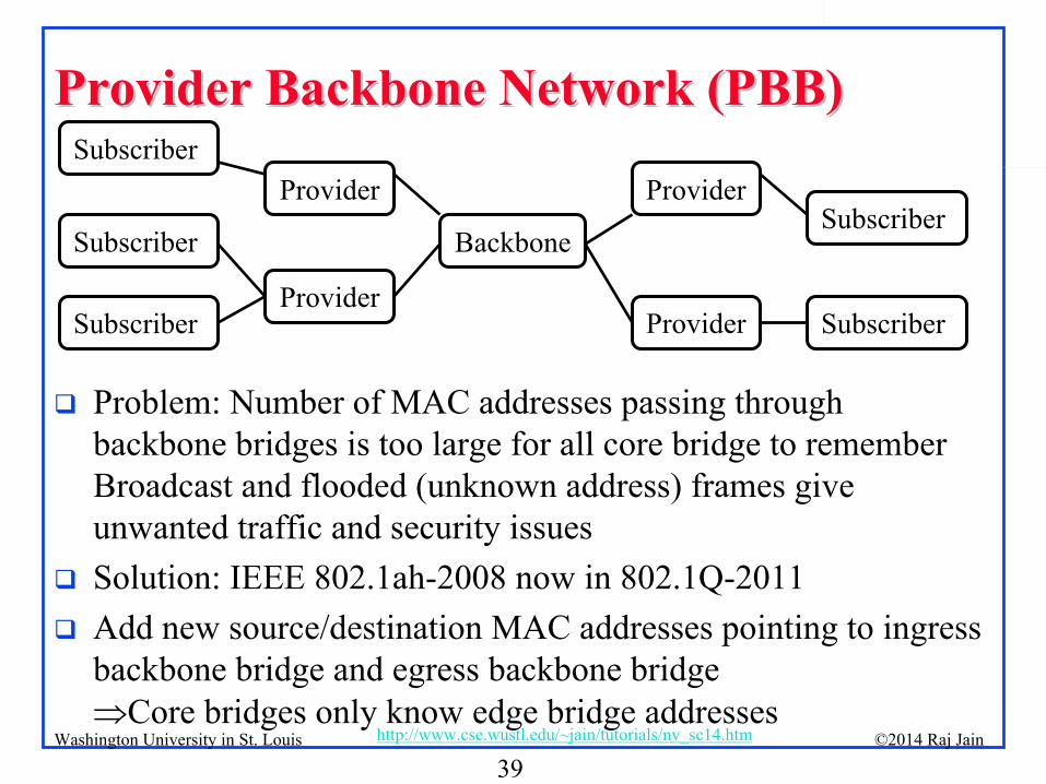
Provider Backbone Network (PBB)Provider Backbone Network (PBB)
Problem: Number of MAC addresses passing through backbone bridges is too large for all core bridge to remember
Broadcast and flooded (unknown address) frames give unwanted traffic and security issues
Solution: IEEE 802.1ah-2008 now in 802.1Q-2011
Add new source/destination MAC addresses pointing to ingress backbone bridge and egress backbone bridge Core bridges only know edge bridge addresses
Subscriber
Provider
Backbone
Provider
Subscriber
Subscriber
Subscriber Provider
Provider
Subscriber
40©2014 Raj Jainhttp://www.cse.wustl.edu/~jain/tutorials/nv_sc14.htmWashington University in St. Louis
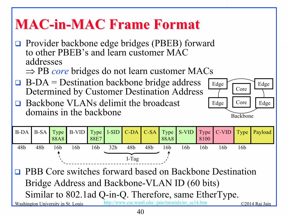
MACMAC--inin--MAC Frame FormatMAC Frame Format
Provider backbone edge bridges (PBEB) forward to other PBEB’s
and learn customer MAC
addresses PB core
bridges do not learn customer MACs
B-DA = Destination backbone bridge address Determined by Customer Destination Address
Backbone VLANs delimit the broadcast domains in the backbone
Type
88A8
Type
88E7
Type88A8
Type8100
B-DA B-SA B-VID I-SID C-DA C-SA S-VID C-VID Type Payload
PBB Core switches forward based on Backbone Destination Bridge Address and Backbone-VLAN ID (60 bits)
Similar to 802.1ad Q-in-Q. Therefore, same EtherType.
48b 48b 16b 16b 16b 32b 48b 48b 16b 16b 16b 16b 16b
I-Tag
Core
Core
Edge
Edge Edge
Edge
Backbone
41©2014 Raj Jainhttp://www.cse.wustl.edu/~jain/tutorials/nv_sc14.htmWashington University in St. Louis
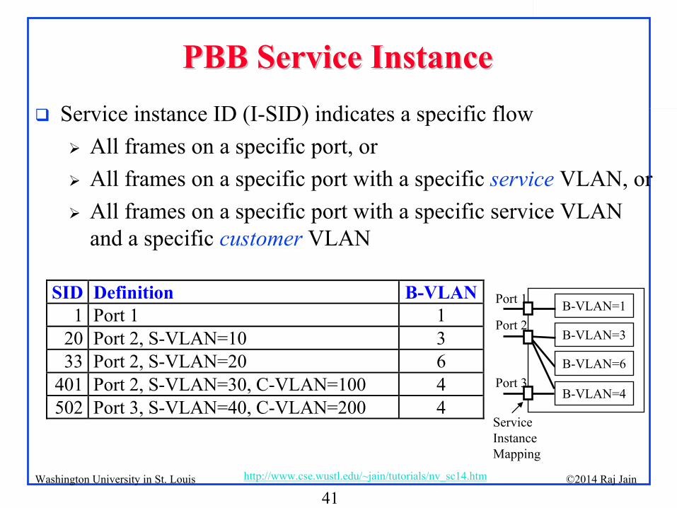
PBB Service InstancePBB Service Instance
Service instance ID (I-SID) indicates a specific flow
All frames on a specific port, or
All frames on a specific port with a specific service
VLAN, or
All frames on a specific port with a specific service VLAN and a specific customer
VLAN
SID Definition B-VLAN1 Port 1 1
20 Port 2, S-VLAN=10 3 33 Port 2, S-VLAN=20 6
401 Port 2, S-VLAN=30, C-VLAN=100 4 502 Port 3, S-VLAN=40, C-VLAN=200 4
B-VLAN=1
B-VLAN=3
B-VLAN=6
B-VLAN=4
Port 1
Port 2
Port 3
Service Instance Mapping
42©2014 Raj Jainhttp://www.cse.wustl.edu/~jain/tutorials/nv_sc14.htmWashington University in St. Louis
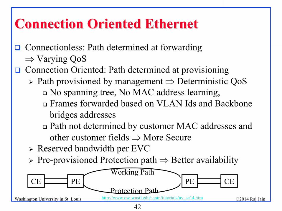
Connection Oriented EthernetConnection Oriented Ethernet
Connectionless: Path determined at forwarding Varying QoS
Connection Oriented: Path determined at provisioning
Path provisioned by management Deterministic QoS
No spanning tree, No MAC address learning,
Frames forwarded based on VLAN Ids and Backbone bridges addresses
Path not determined by customer MAC addresses and other customer fields More Secure
Reserved bandwidth per EVC
Pre-provisioned Protection path Better availability
PE PECE CEWorking Path
Protection Path
43©2014 Raj Jainhttp://www.cse.wustl.edu/~jain/tutorials/nv_sc14.htmWashington University in St. Louis
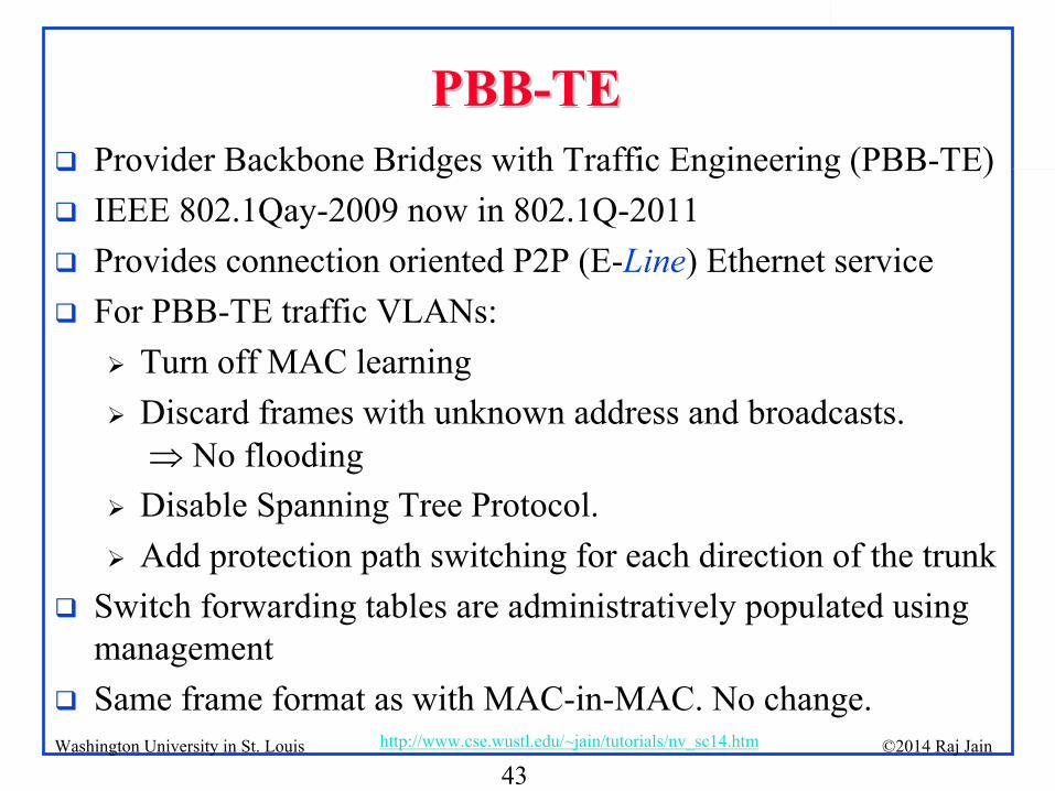
PBBPBB--TETE
Provider Backbone Bridges with Traffic Engineering (PBB-TE)
IEEE 802.1Qay-2009 now in 802.1Q-2011
Provides connection oriented P2P (E-Line) Ethernet service
For PBB-TE traffic VLANs:
Turn off MAC learning
Discard frames with unknown address and broadcasts. No flooding
Disable Spanning Tree Protocol.
Add protection path switching for each direction of the trunk
Switch forwarding tables are administratively populated using management
Same frame format as with MAC-in-MAC. No change.
44©2014 Raj Jainhttp://www.cse.wustl.edu/~jain/tutorials/nv_sc14.htmWashington University in St. Louis
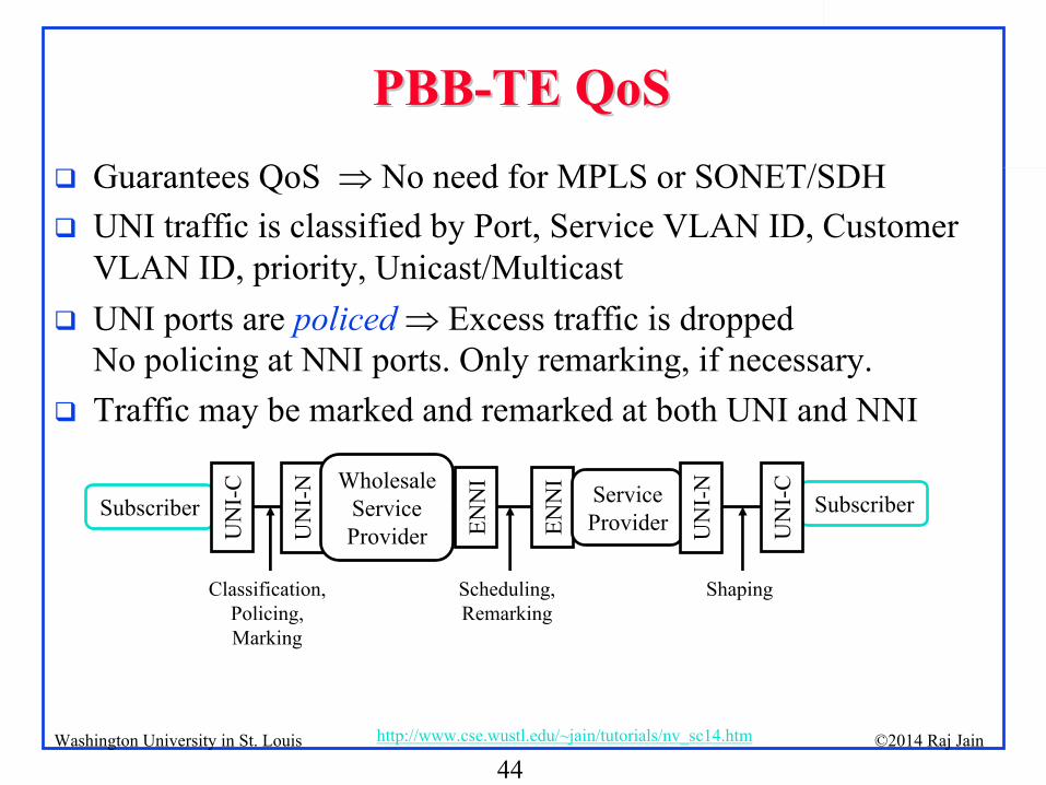
PBBPBB--TE QoSTE QoS
Guarantees QoS No need for MPLS or SONET/SDH
UNI traffic is classified by Port, Service VLAN ID, Customer VLAN ID, priority, Unicast/Multicast
UNI ports are
policed
Excess traffic is dropped No policing at NNI ports. Only remarking, if necessary.
Traffic may be marked and remarked at both UNI and NNI
Subscriber
UN
I-C
ENN
I Service
Provider U
NI-
N
Subscriber
UN
I-C
UN
I-N
ENN
IWholesale
ServiceProvider
Classification,
Policing,Marking
Scheduling,
Remarking
Shaping
45©2014 Raj Jainhttp://www.cse.wustl.edu/~jain/tutorials/nv_sc14.htmWashington University in St. Louis
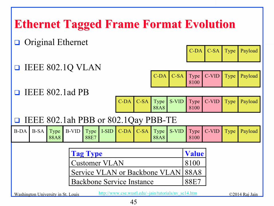
Ethernet Tagged Frame Format EvolutionEthernet Tagged Frame Format Evolution
Type
88A8
Type
88E7
Type88A8
Type8100
B-DA B-SA B-VID I-SID C-DA C-SA S-VID C-VID Type Payload
Type88A8
Type8100
C-DA C-SA S-VID C-VID Type Payload
Type8100
C-DA C-SA C-VID Type Payload
C-DA C-SA Type Payload
Original Ethernet
IEEE 802.1Q VLAN
IEEE 802.1ad PB
IEEE 802.1ah PBB or 802.1Qay PBB-TE
Tag Type ValueCustomer VLAN 8100Service VLAN or Backbone VLAN 88A8Backbone Service Instance 88E7
46©2014 Raj Jainhttp://www.cse.wustl.edu/~jain/tutorials/nv_sc14.htmWashington University in St. Louis
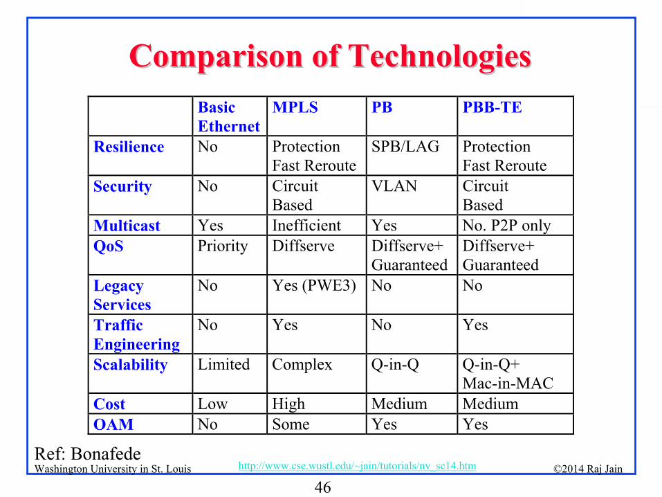
Comparison of TechnologiesComparison of Technologies
Ref: Bonafede
Basic Ethernet
MPLS PB PBB-TE
Resilience No Protection Fast Reroute
SPB/LAG Protection Fast Reroute
Security No Circuit Based
VLAN Circuit Based
Multicast Yes Inefficient Yes No. P2P only QoS Priority Diffserve Diffserve+
Guaranteed Diffserve+ Guaranteed
Legacy Services
No Yes (PWE3) No No
Traffic Engineering
No Yes No Yes
Scalability Limited Complex Q-in-Q Q-in-Q+ Mac-in-MAC
Cost Low High Medium Medium OAM No Some Yes Yes
47©2014 Raj Jainhttp://www.cse.wustl.edu/~jain/tutorials/nv_sc14.htmWashington University in St. Louis
Summary of Part IIISummary of Part III
1.
PB Q-in-Q extension allows Internet/Cloud service providers to allow customers to have their own VLAN IDs
2.
PBB MAC-in-MAC extension allows customers/tenants to have their own MAC addresses and allows service providers to not have to worry about them in the core switches
3.
PBB allows very large Ethernet networks spanning over several backbone carriers
4.
PBB-TE extension allows connection oriented Ethernet with QoS guarantees and protection
48©2014 Raj Jainhttp://www.cse.wustl.edu/~jain/tutorials/nv_sc14.htmWashington University in St. Louis
Part IV: Virtual BridgingPart IV: Virtual Bridging
1.
Virtual Bridges to connect virtual machines2.
IEEE Virtual Edge Bridging Standard 3.
Single Root I/O Virtualization (SR-IOV)4.
Aggregating Bridges and Links: VSS and vPC5.
Bridges with massive number of ports: VBE
49©2014 Raj Jainhttp://www.cse.wustl.edu/~jain/tutorials/nv_sc14.htmWashington University in St. Louis
vSwitchvSwitch
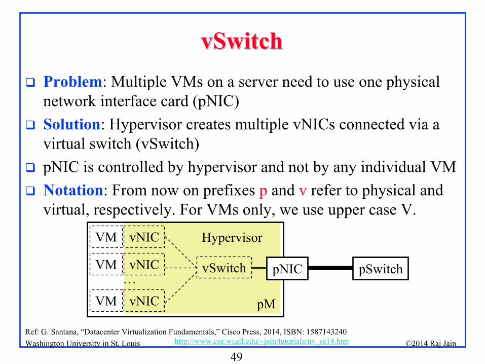
Problem: Multiple VMs on a server need to use one physical network interface card (pNIC)
Solution: Hypervisor creates multiple vNICs connected via a virtual switch (vSwitch)
pNIC is controlled by hypervisor and not by any individual VM
Notation: From now on prefixes p
and v
refer to physical and virtual, respectively. For VMs only, we use upper case V.
Ref: G. Santana, “Datacenter Virtualization Fundamentals,”
Cisco Press, 2014, ISBN: 1587143240
pSwitch
VM vNIC
pM
Hypervisor
VM vNIC
VM vNIC…
pNICvSwitch
50©2014 Raj Jainhttp://www.cse.wustl.edu/~jain/tutorials/nv_sc14.htmWashington University in St. Louis
Virtual BridgingVirtual Bridging
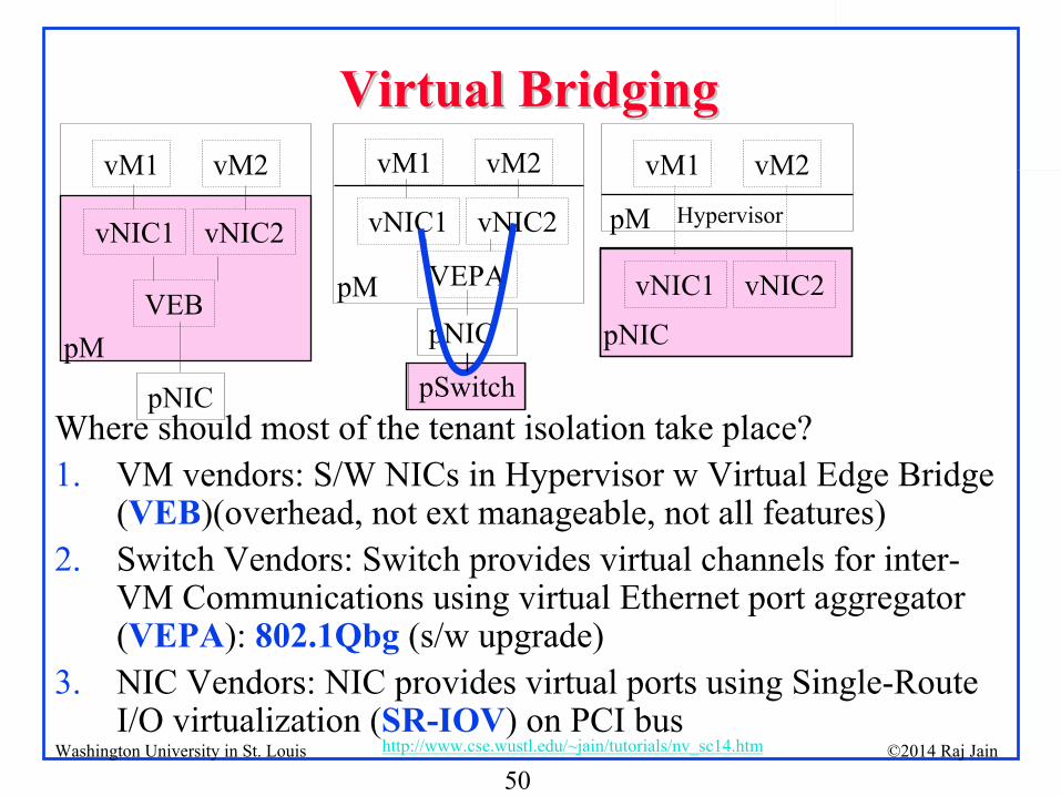
Where should most of the tenant isolation take place?1.
VM vendors: S/W NICs in Hypervisor w Virtual Edge Bridge (VEB)(overhead, not ext manageable, not all features)
2.
Switch Vendors: Switch provides virtual channels for inter- VM Communications using virtual Ethernet port aggregator
(VEPA): 802.1Qbg
(s/w upgrade)3.
NIC Vendors: NIC provides virtual ports using Single-Route I/O virtualization (SR-IOV) on PCI bus
vM1 vM2
vNIC1 vNIC2
pNIC
HypervisorpM
vM1 vM2
vNIC1 vNIC2
VEPA
pNICpM
pSwitch
vM1 vM2
vNIC1 vNIC2
VEB
pNIC
pM
51©2014 Raj Jainhttp://www.cse.wustl.edu/~jain/tutorials/nv_sc14.htmWashington University in St. Louis
Virtual Edge BridgeVirtual Edge Bridge
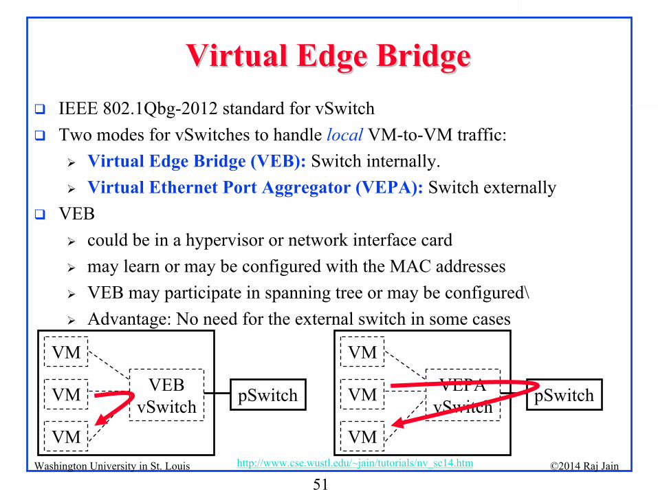
IEEE 802.1Qbg-2012 standard for vSwitch
Two modes for vSwitches to handle local
VM-to-VM traffic:
Virtual Edge Bridge (VEB):
Switch internally.
Virtual Ethernet Port Aggregator (VEPA):
Switch externally
VEB
could be in a hypervisor or network interface card
may learn or may be configured with the MAC addresses
VEB may participate in spanning tree or may be configured\
Advantage: No need for the external switch in some cases
VEB
vSwitch pSwitch
VM
VM
VM
VEPA
vSwitch pSwitch
VM
VM
VM
52©2014 Raj Jainhttp://www.cse.wustl.edu/~jain/tutorials/nv_sc14.htmWashington University in St. Louis
Virtual Ethernet Port Aggregator (VEPA)Virtual Ethernet Port Aggregator (VEPA)
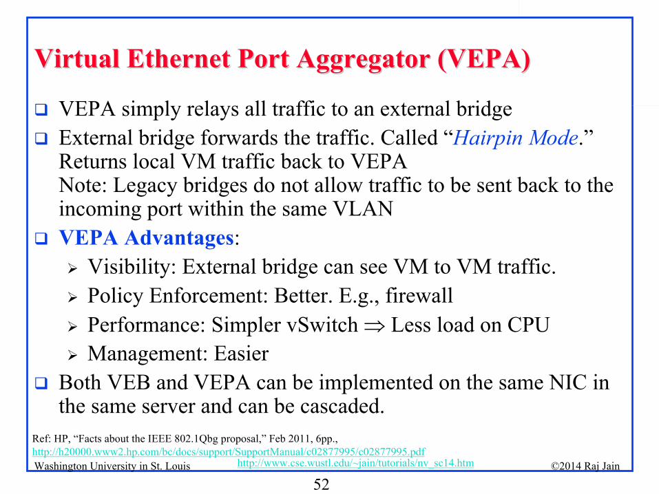
VEPA simply relays all traffic to an external bridge
External bridge forwards the traffic. Called “Hairpin Mode.” Returns local VM traffic back to VEPA
Note: Legacy bridges do not allow traffic to be sent back to the incoming port within the same VLAN
VEPA Advantages:
Visibility: External bridge can see VM to VM traffic.
Policy Enforcement: Better. E.g., firewall
Performance: Simpler vSwitch Less load on CPU
Management: Easier
Both VEB and VEPA can be implemented on the same NIC in the same server and can be cascaded.
Ref: HP, “Facts about the IEEE 802.1Qbg proposal,”
Feb 2011, 6pp., http://h20000.www2.hp.com/bc/docs/support/SupportManual/c02877995/c02877995.pdf

53©2014 Raj Jainhttp://www.cse.wustl.edu/~jain/tutorials/nv_sc14.htmWashington University in St. Louis
Combining BridgesCombining Bridges
Problem:
Number of VMs is growing very fast
Need switches with very large number of ports
Easy to manage one bridge than 100 10-port bridges
How to make very large switches ~1000 ports?
Solutions: Multiple pSwitches to form a single switch 1.
Fabric Extension (FEX) 2.
Virtual Bridge Port Extension (VBE)
54©2014 Raj Jainhttp://www.cse.wustl.edu/~jain/tutorials/nv_sc14.htmWashington University in St. Louis
Fabric ExtendersFabric Extenders
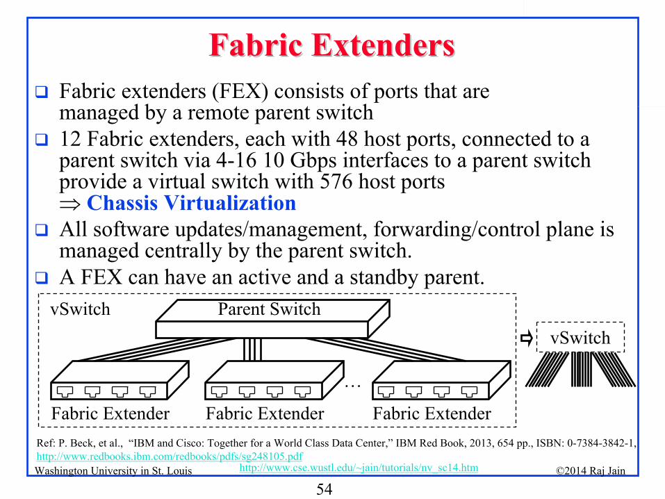
Fabric extenders (FEX) consists of ports that are managed by a remote parent switch
12 Fabric extenders, each with 48 host ports, connected to a parent switch via 4-16 10 Gbps interfaces to a parent switch provide a virtual switch with 576 host ports Chassis Virtualization
All software updates/management, forwarding/control plane is managed centrally by the parent switch.
A FEX can have an active and a standby parent.
Fabric Extender
Parent Switch
Fabric Extender Fabric Extender
…
vSwitch
Ref: P. Beck, et al., “IBM and Cisco: Together for a World Class Data Center,”
IBM Red Book, 2013, 654 pp., ISBN: 0-7384-3842-1, http://www.redbooks.ibm.com/redbooks/pdfs/sg248105.pdf
vSwitch
55©2014 Raj Jainhttp://www.cse.wustl.edu/~jain/tutorials/nv_sc14.htmWashington University in St. Louis
Virtual Bridge Port Extension (VBE)Virtual Bridge Port Extension (VBE)
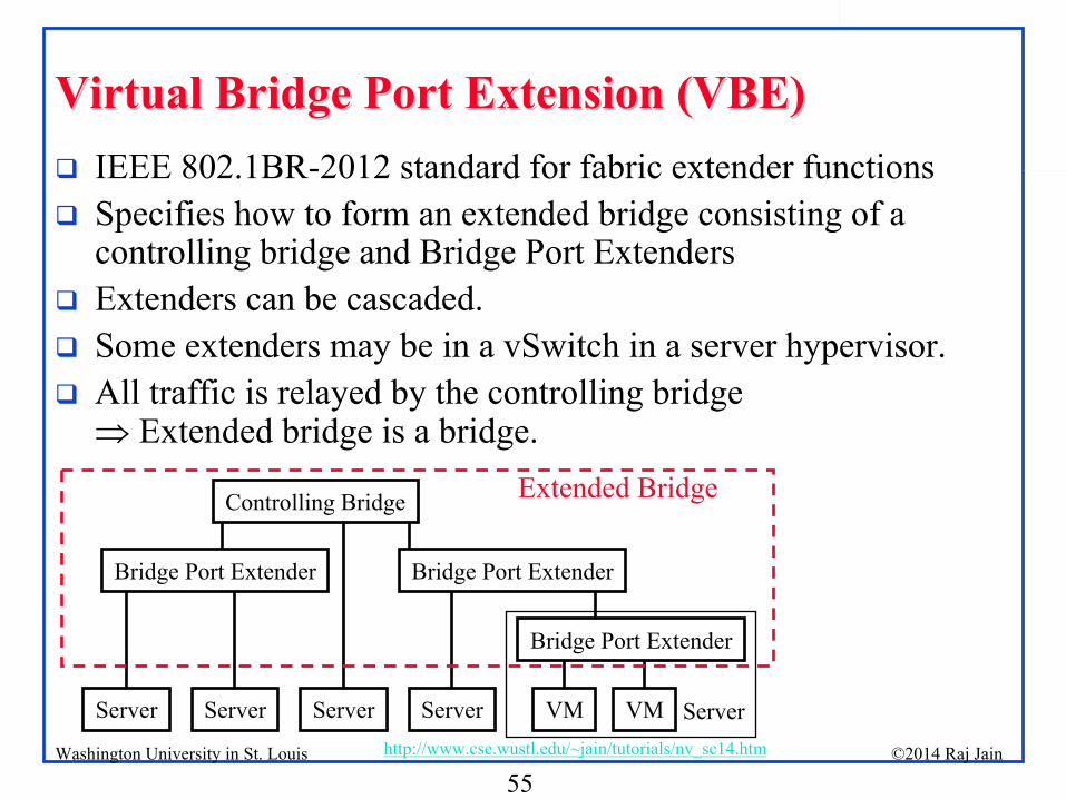
IEEE 802.1BR-2012 standard for fabric extender functions
Specifies how to form an extended bridge consisting of a controlling bridge and Bridge Port Extenders
Extenders can be cascaded.
Some extenders may be in a vSwitch in a server hypervisor.
All traffic is relayed by the controlling bridge Extended bridge is a bridge.
Controlling Bridge
Bridge Port Extender
Bridge Port Extender Bridge Port Extender
Server Server Server VMServer VM Server
Extended Bridge
56©2014 Raj Jainhttp://www.cse.wustl.edu/~jain/tutorials/nv_sc14.htmWashington University in St. Louis
Summary of Part IVSummary of Part IV
1.
Network virtualization includes virtualization of NICs, Bridges, Routers, and L2 networks.
2.
Virtual Edge Bridge (VEB) vSwitches switch internally while Virtual Ethernet Port Aggregator (VEPA) vSwitches switch externally.
3.
Fabric Extension and Virtual Bridge Extension (VBE) allows creating switches with a large number of ports using port extenders (which may be vSwitches)
57©2014 Raj Jainhttp://www.cse.wustl.edu/~jain/tutorials/nv_sc14.htmWashington University in St. Louis
Part V: LAN Extension and PartitioningPart V: LAN Extension and Partitioning
1.
Transparent Interconnection of Lots of Links (TRILL)
2.
Network Virtualization using GRE (NVGRE)3.
Virtual eXtensible
LANs (VXLAN)4.
Stateless Transport Tunneling Protocol (STT)
LAN
58©2014 Raj Jainhttp://www.cse.wustl.edu/~jain/tutorials/nv_sc14.htmWashington University in St. Louis
Challenges of LAN ExtensionChallenges of LAN Extension
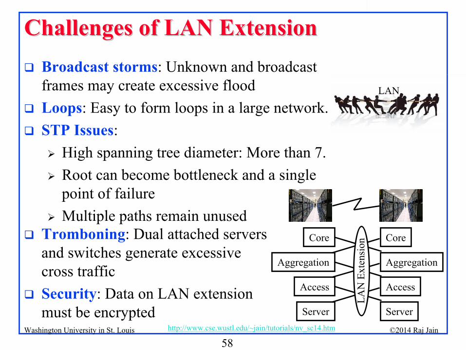
Broadcast storms: Unknown and broadcast frames may create excessive flood
Loops: Easy to form loops in a large network.
STP Issues:
High spanning tree diameter: More than 7.
Root can become bottleneck and a single point of failure
Multiple paths remain unusedCore
Aggregation
Access
Server
Core
Aggregation
Access
Server
LAN
Ext
ensi
on
Tromboning: Dual attached servers and switches generate excessive cross traffic
Security: Data on LAN extension must be encrypted
LAN
59©2014 Raj Jainhttp://www.cse.wustl.edu/~jain/tutorials/nv_sc14.htmWashington University in St. Louis
TRILLTRILL
Transparent Interconnection of Lots of Links
Allows a large campus to be a single extended LAN
LANs allow free mobility inside the LAN but:
Inefficient paths using Spanning tree
Inefficient link utilization since many links are disabled
Inefficient link utilization since multipath is not allowed.
Unstable: small changes in network large changes in spanning tree
IP subnets are not good for mobility because IP addresses change as nodes move and break transport connections, but:
IP routing is efficient, optimal, and stable
Solution: Take the best of both worlds Use MAC addresses and IP routing
Ref: RFCs 5556, 6325, 6326, 6327, 6361, 6439
60©2014 Raj Jainhttp://www.cse.wustl.edu/~jain/tutorials/nv_sc14.htmWashington University in St. Louis
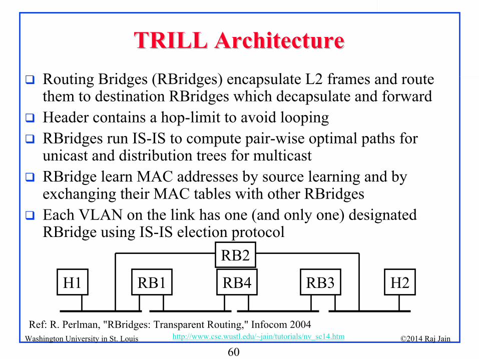
TRILL ArchitectureTRILL Architecture
Routing Bridges (RBridges) encapsulate L2 frames and route them to destination RBridges which decapsulate and forward
Header contains a hop-limit to avoid looping
RBridges run IS-IS to compute pair-wise optimal paths for unicast and distribution trees for multicast
RBridge learn MAC addresses by source learning and by exchanging their MAC tables with other RBridges
Each VLAN on the link has one (and only one) designated RBridge using IS-IS election protocol
Ref: R. Perlman, "RBridges: Transparent Routing," Infocom 2004
RB1 RB3H1 H2
RB2
RB4
61©2014 Raj Jainhttp://www.cse.wustl.edu/~jain/tutorials/nv_sc14.htmWashington University in St. Louis
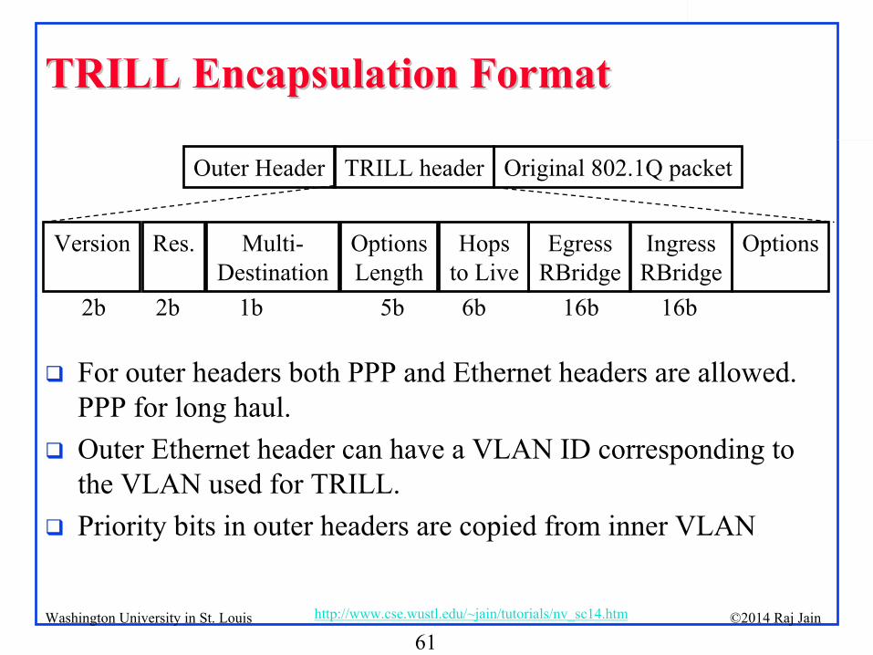
TRILL Encapsulation FormatTRILL Encapsulation Format
For outer headers both PPP and Ethernet headers are allowed. PPP for long haul.
Outer Ethernet header can have a VLAN ID corresponding to the VLAN used for TRILL.
Priority bits in outer headers are copied from inner VLAN
Outer Header TRILL header Original 802.1Q packet
2b 2b 1b 5b 6b 16b 16b
Version Res. Multi-
DestinationOptions
LengthHops
to LiveEgress
RBridgeIngress
RBridgeOptions
62©2014 Raj Jainhttp://www.cse.wustl.edu/~jain/tutorials/nv_sc14.htmWashington University in St. Louis
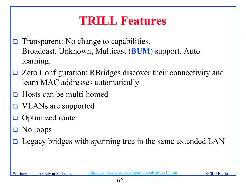
TRILL FeaturesTRILL Features
Transparent: No change to capabilities. Broadcast, Unknown, Multicast (BUM) support. Auto-
learning.
Zero Configuration: RBridges discover their connectivity and learn MAC addresses automatically
Hosts can be multi-homed
VLANs are supported
Optimized route
No loops
Legacy bridges with spanning tree in the same extended LAN
63©2014 Raj Jainhttp://www.cse.wustl.edu/~jain/tutorials/nv_sc14.htmWashington University in St. Louis
TRILL: SummaryTRILL: Summary
TRILL allows a large campus to be a single Extended LAN
Packets are encapsulated and routed using IS-IS routing
64©2014 Raj Jainhttp://www.cse.wustl.edu/~jain/tutorials/nv_sc14.htmWashington University in St. Louis
GREGRE
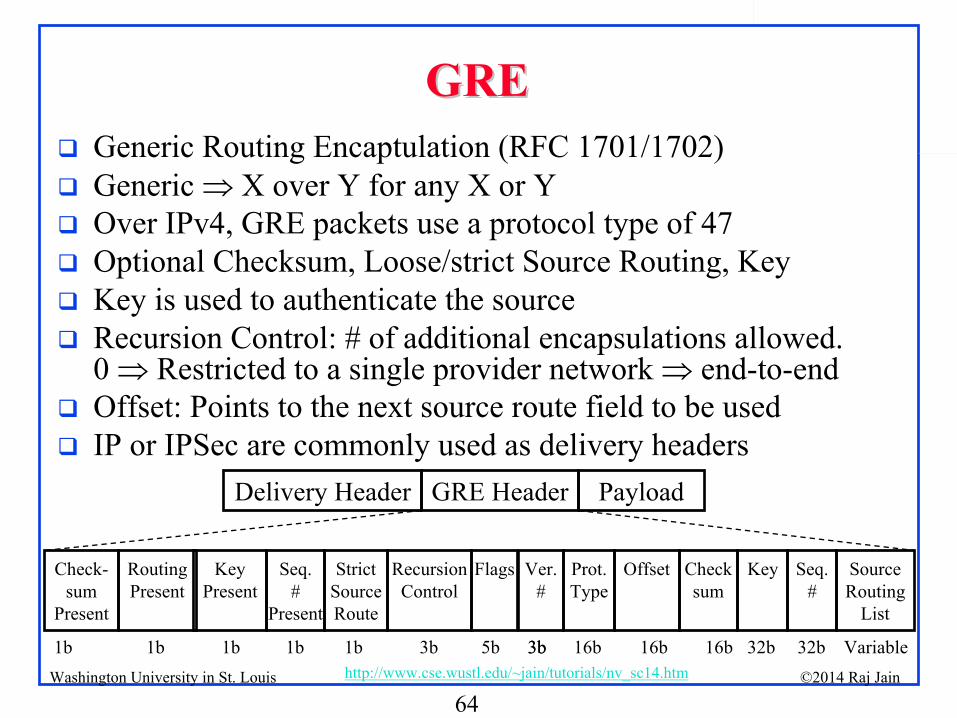
Generic Routing Encaptulation
(RFC 1701/1702)
Generic X over Y for any X or Y
Over IPv4, GRE packets use a protocol type of 47
Optional Checksum, Loose/strict Source Routing, Key
Key is used to authenticate the source
Recursion Control: # of additional encapsulations allowed. 0 Restricted to a single provider network end-to-end
Offset: Points to the next source route field to be used
IP or IPSec are commonly used as delivery headersPayloadGRE HeaderDelivery Header
Check-
sum
Present
Routing
Present
Key
Present
Seq.
#
Present
Strict
Source
Route
Ver.
#
Prot.
Type
Offset Check
sum
Key Seq.
#
Source
Routing
List
1b 1b 1b 1b 3b 3b 16b 16b 16b 32b 32b Variable
Recursion
Control
1b 3b
Flags
5b

65©2014 Raj Jainhttp://www.cse.wustl.edu/~jain/tutorials/nv_sc14.htmWashington University in St. Louis
NVGRENVGRE
Network Virtualization using GRE Ethernet over GRE over IP (point-to-point)
A unique 24-bit Virtual Subnet Identifier (VSID) is used as the lower 24-bits of GRE key field 224
tenants can share
Unique IP multicast address is used for BUM (Broadcast, Unknown, Multicast) traffic on each VSID
Equal Cost Multipath (ECMP) allowed on point-to-point tunnels
Customer
EdgeSwitch
Customer
EdgeSwitch
Provider
Edge
Router
Provider
Core
Router(s)
Provider
Edge
Router
Tunnel
EthernetEthernetGREIPEthernet EthernetGREIP =
Provider Network
Ref: M. Sridharan, “MVGRE: Network Virtualization using GRE,”
Aug 2013, http://tools.ietf.org/html/draft-sridharan-virtualization-nvgre-03
66©2014 Raj Jainhttp://www.cse.wustl.edu/~jain/tutorials/nv_sc14.htmWashington University in St. Louis
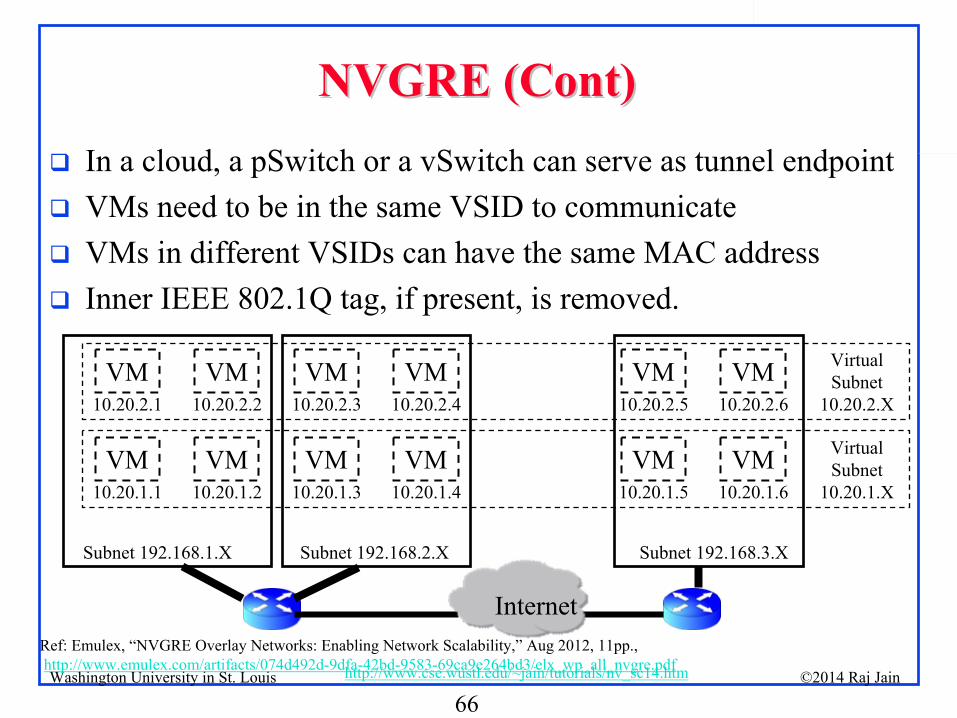
NVGRE (Cont)NVGRE (Cont)
In a cloud, a pSwitch or a vSwitch can serve as tunnel endpoint
VMs need to be in the same VSID to communicate
VMs in different VSIDs
can have the same MAC address
Inner IEEE 802.1Q tag, if present, is removed.
Ref: Emulex, “NVGRE Overlay Networks: Enabling Network Scalability,”
Aug 2012, 11pp., http://www.emulex.com/artifacts/074d492d-9dfa-42bd-9583-69ca9e264bd3/elx_wp_all_nvgre.pdf
Virtual
Subnet
10.20.2.XVM
10.20.2.1VM
10.20.2.2VM
10.20.2.3VM
10.20.2.4VM
10.20.2.5VM
10.20.2.6
VM10.20.1.1
VM10.20.1.2
VM10.20.1.3
VM10.20.1.4
VM10.20.1.5
VM10.20.1.6
Virtual
Subnet
10.20.1.X
Subnet 192.168.1.X Subnet 192.168.2.X Subnet 192.168.3.X
Internet
67©2014 Raj Jainhttp://www.cse.wustl.edu/~jain/tutorials/nv_sc14.htmWashington University in St. Louis
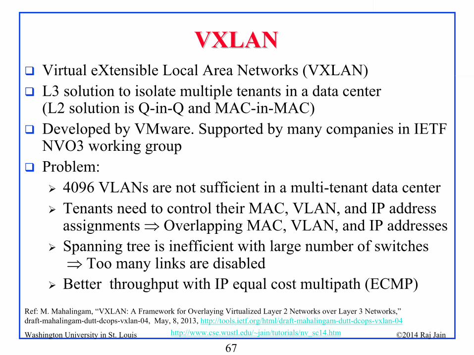
VXLANVXLAN
Virtual eXtensible
Local Area Networks (VXLAN)
L3 solution to isolate multiple tenants in a data center (L2 solution is Q-in-Q and MAC-in-MAC)
Developed by VMware. Supported by many companies in IETF NVO3 working group
Problem:
4096 VLANs are not sufficient in a multi-tenant data center
Tenants need to control their MAC, VLAN, and IP address assignments Overlapping MAC, VLAN, and IP addresses
Spanning tree is inefficient with large number of switches Too many links are disabled
Better throughput with IP equal cost multipath (ECMP)Ref: M. Mahalingam, “VXLAN: A Framework for Overlaying Virtualized Layer 2 Networks over Layer 3 Networks,”
draft-mahalingam-dutt-dcops-vxlan-04, May, 8, 2013, http://tools.ietf.org/html/draft-mahalingam-dutt-dcops-vxlan-04
68©2014 Raj Jainhttp://www.cse.wustl.edu/~jain/tutorials/nv_sc14.htmWashington University in St. Louis
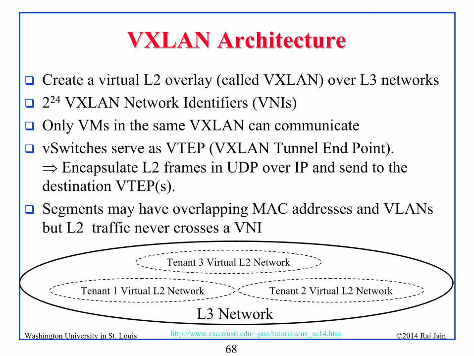
VXLAN ArchitectureVXLAN Architecture
Create a virtual L2 overlay (called VXLAN) over L3 networks
224
VXLAN Network Identifiers (VNIs)
Only VMs in the same VXLAN can communicate
vSwitches serve as VTEP (VXLAN Tunnel End Point). Encapsulate L2 frames in UDP over IP and send to the
destination VTEP(s).
Segments may have overlapping MAC addresses and VLANs but L2 traffic never crosses a VNI
L3 NetworkTenant 1 Virtual L2 Network Tenant 2 Virtual L2 Network
Tenant 3 Virtual L2 Network
69©2014 Raj Jainhttp://www.cse.wustl.edu/~jain/tutorials/nv_sc14.htmWashington University in St. Louis
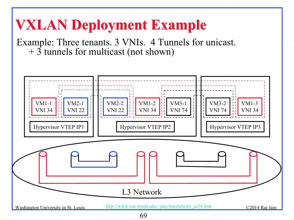
VXLAN Deployment ExampleVXLAN Deployment ExampleExample: Three tenants. 3 VNIs. 4 Tunnels for unicast.
+ 3 tunnels for multicast (not shown)
VM2-1
VNI 22
VM1-1
VNI 34
VM2-2
VNI 22
Hypervisor VTEP IP1
VM3-2
VNI 74
VM1-3
VNI 34
Hypervisor VTEP IP3
VM3-1
VNI 74
Hypervisor VTEP IP2
VM1-2
VNI 34
L3 Network

70©2014 Raj Jainhttp://www.cse.wustl.edu/~jain/tutorials/nv_sc14.htmWashington University in St. Louis
VXLAN Encapsulation FormatVXLAN Encapsulation Format
Outer VLAN tag is optional. Used to isolate VXLAN traffic on the LAN
Source VM ARPs
to find Destination VM’s
MAC address. All L2 multicasts/unknown are sent via IP multicast.
Destination VM sends a standard IP unicast ARP response.
Destination VTEP learns inner-Src-MAC-to-outer-src-IP mapping
Avoids unknown destination flooding for returning responses
Flags Res VNI Res8b 24b 24b 8b
Dest.
VTEP
MAC
Source
VTEP
MAC
Outer
VLAN
Dest. VTEP
IP
Source VTEP
IP
UDP
Header
VXLAN
Header
Dest
VM
MAC
Source
VM
MAC
Tenant
VLAN
Ethernet
Payload
Only key fields are shown
71©2014 Raj Jainhttp://www.cse.wustl.edu/~jain/tutorials/nv_sc14.htmWashington University in St. Louis
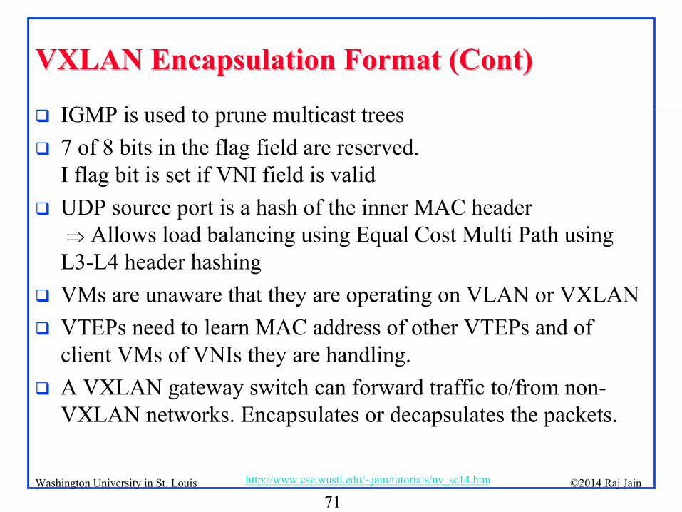
VXLAN Encapsulation Format (Cont)VXLAN Encapsulation Format (Cont)
IGMP is used to prune multicast trees
7 of 8 bits in the flag field are reserved. I flag bit is set if VNI field is valid
UDP source port is a hash of the inner MAC header
Allows load balancing using Equal Cost Multi Path using L3-L4 header hashing
VMs are unaware that they are operating on VLAN or VXLAN
VTEPs need to learn MAC address of other VTEPs and of client VMs of VNIs they are handling.
A VXLAN gateway switch can forward traffic to/from non- VXLAN networks. Encapsulates or decapsulates the packets.
72©2014 Raj Jainhttp://www.cse.wustl.edu/~jain/tutorials/nv_sc14.htmWashington University in St. Louis
VXLAN: SummaryVXLAN: Summary
VXLAN solves the problem of multiple tenants with overlapping MAC addresses, VLANs, and IP addresses in a cloud environment.
A server may have VMs belonging to different tenants
No changes to VMs. Hypervisors responsible for all details.
Uses UDP over IP encapsulation to isolate tenants
73©2014 Raj Jainhttp://www.cse.wustl.edu/~jain/tutorials/nv_sc14.htmWashington University in St. Louis
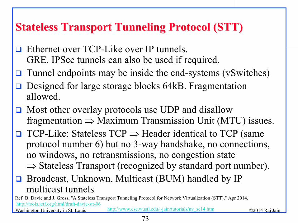
Stateless Transport Tunneling Protocol (STT)Stateless Transport Tunneling Protocol (STT)
Ethernet over TCP-Like over IP tunnels. GRE, IPSec tunnels can also be used if required.
Tunnel endpoints may be inside the end-systems (vSwitches)
Designed for large storage blocks 64kB. Fragmentation allowed.
Most other overlay protocols use UDP and disallow fragmentation Maximum Transmission Unit (MTU) issues.
TCP-Like: Stateless TCP Header identical to TCP (same protocol number 6) but no 3-way handshake, no connections, no windows, no retransmissions, no congestion state Stateless Transport (recognized by standard port number).
Broadcast, Unknown, Multicast (BUM) handled by IP multicast tunnels
Ref: B. Davie and J. Gross, "A Stateless Transport Tunneling Protocol for Network Virtualization (STT)," Apr 2014,
http://tools.ietf.org/html/draft-davie-stt-06

74©2014 Raj Jainhttp://www.cse.wustl.edu/~jain/tutorials/nv_sc14.htmWashington University in St. Louis
LSO and LROLSO and LRO
Large Send Offload (LSO): Host hands a large chunk of data to NIC and meta data. NIC makes MSS size segments, adds checksum, TCP, IP, and MAC headers to each segment.
Large Receive Offload (LRO): NICs attempt to reassemble multiple TCP segments and pass larger chunks to the host. Host does the final reassembly with fewer per packet operations.
STT takes advantage of LSO and LRO features, if available.
Using a protocol number other than 6 will not allow LSO/LRO to handle STT
Host
LSO
Meta Data Payload
L2 Header IP Header TCP Header Segment
LRO
75©2014 Raj Jainhttp://www.cse.wustl.edu/~jain/tutorials/nv_sc14.htmWashington University in St. Louis
STT OptimizationsSTT Optimizations
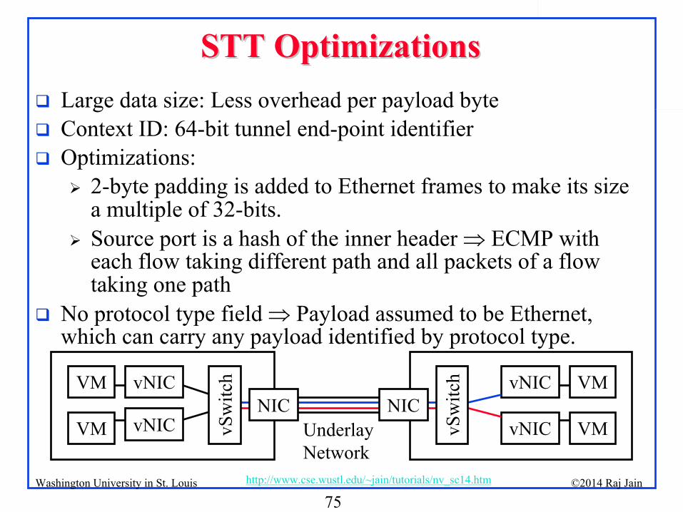
Large data size: Less overhead per payload byte
Context ID: 64-bit tunnel end-point identifier
Optimizations:
2-byte padding is added to Ethernet frames to make its size a multiple of 32-bits.
Source port is a hash of the inner header ECMP with each flow taking different path and all packets of a flow taking one path
No protocol type field Payload assumed to be Ethernet, which can carry any payload identified by protocol type.
VM
VM
vNIC
vNICvSw
itch
NIC
vSw
itch
NICUnderlay
Network
vNIC
vNIC
VM
VM
76©2014 Raj Jainhttp://www.cse.wustl.edu/~jain/tutorials/nv_sc14.htmWashington University in St. Louis
STT Frame FormatSTT Frame Format
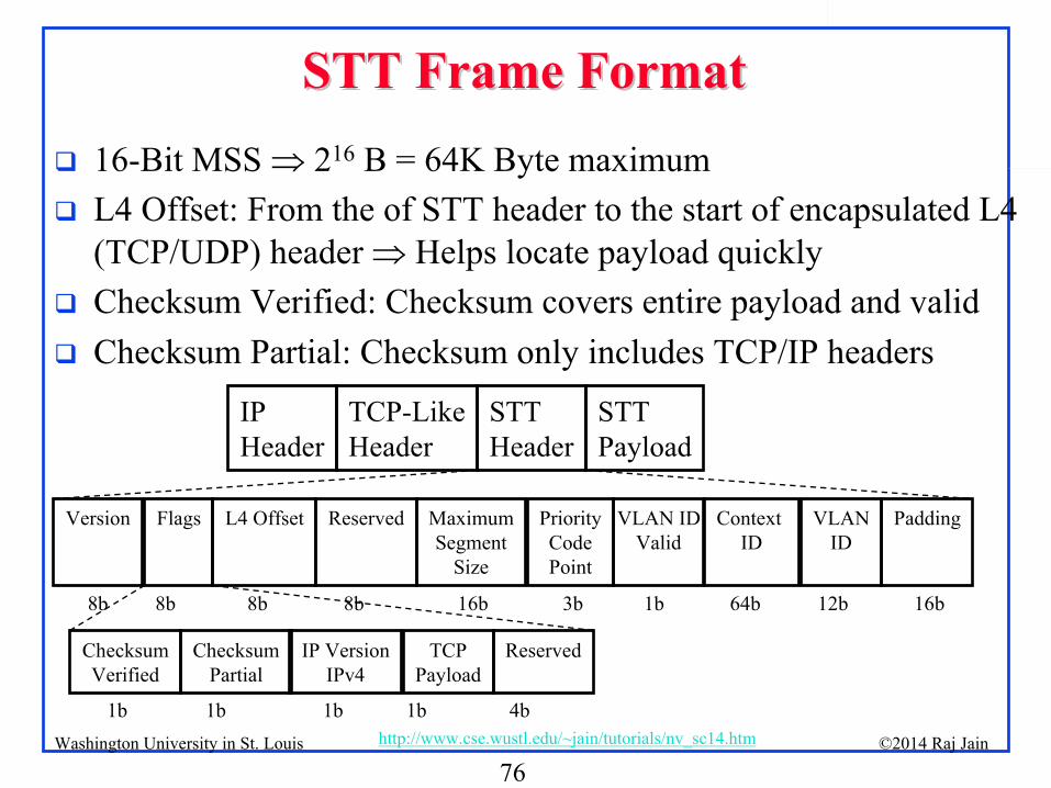
16-Bit MSS 216
B = 64K Byte maximum
L4 Offset: From the of STT header to the start of encapsulated L4 (TCP/UDP) header Helps locate payload quickly
Checksum Verified: Checksum covers entire payload and valid
Checksum Partial: Checksum only includes TCP/IP headers
MaximumSegment
Size
Priority
Code
Point
VLAN
ID
Context ID
Version Flags L4 Offset Reserved VLAN IDValid
Padding
8b 8b 8b 8b 16b 3b 1b 64b 12b
IP
HeaderTCP-Like
HeaderSTT
HeaderSTT
Payload
16b
Checksum
Verified
Checksum
Partial
IP Version
IPv4
TCP
Payload
Reserved
1b 1b 1b 1b 4b
77©2014 Raj Jainhttp://www.cse.wustl.edu/~jain/tutorials/nv_sc14.htmWashington University in St. Louis
TCPTCP--Like Header in STTLike Header in STT
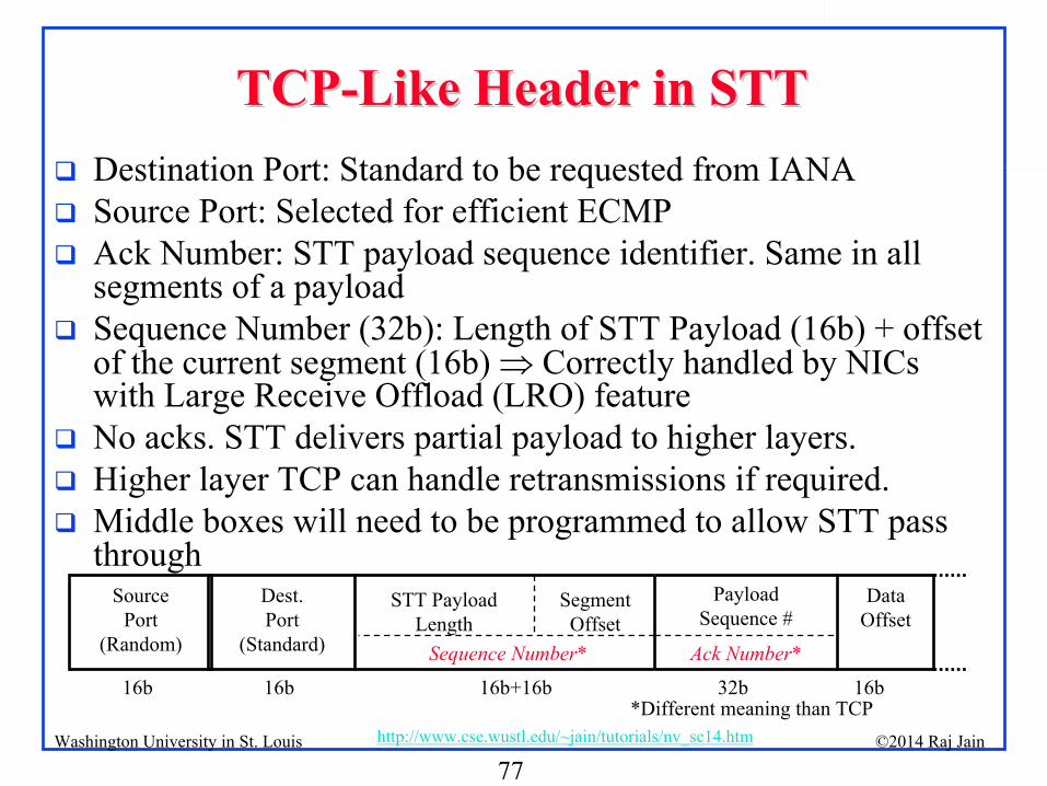
Destination Port: Standard to be requested from IANA
Source Port: Selected for efficient ECMP
Ack Number: STT payload sequence identifier. Same in all segments of a payload
Sequence Number (32b): Length of STT Payload (16b) + offset of the current segment (16b) Correctly handled by NICs with Large Receive Offload (LRO) feature
No acks. STT delivers partial payload to higher layers.
Higher layer TCP can handle retransmissions if required.
Middle boxes will need to be programmed to allow STT pass through
Source
Port
(Random)
Dest.
Port
(Standard)
STT Payload
Length
Segment
Offset
Payload
Sequence #
Data
Offset
Sequence Number* Ack Number*
16b 16b 16b+16b 32b 16b*Different meaning than TCP
78©2014 Raj Jainhttp://www.cse.wustl.edu/~jain/tutorials/nv_sc14.htmWashington University in St. Louis
STT SummarySTT Summary
STT solves the problem of efficient
transport of large 64 KB storage blocks
Uses Ethernet over TCP-Like over IP tunnels
Designed for software implementation in hypervisors
79©2014 Raj Jainhttp://www.cse.wustl.edu/~jain/tutorials/nv_sc14.htmWashington University in St. Louis
Summary of Part VSummary of Part V
1.
TRILL allows Ethernet to span a large campus using IS-IS encapsulation
2.
NVGRE uses Ethernet over GRE for L2 connectivity.3.
VXLAN uses Ethernet over UDP over IP4.
STT uses Ethernet over TCP-like stateless protocol over IP.
80©2014 Raj Jainhttp://www.cse.wustl.edu/~jain/tutorials/nv_sc14.htmWashington University in St. Louis
Overall SummaryOverall Summary
1.
Virtualization allows applications to use resources without worrying about its location, size, format etc.
2.
Ethernet’s use of IDs as addresses makes it very easy to move systems in the data center Keep traffic on the same Ethernet
3.
Cloud computing requires Ethernet to be extended globally and partitioned for sharing by a very large number of customers who have complete control over their address assignment and connectivity and requires rapid provisioning of a large number of virtual NICs and switches
4.
Spanning tree is wasteful of resources and slow. Ethernet now uses shortest path bridging (similar to OSPF)
81©2014 Raj Jainhttp://www.cse.wustl.edu/~jain/tutorials/nv_sc14.htmWashington University in St. Louis
Overall Summary (Cont)Overall Summary (Cont)5.
Data center bridging extensions reduce the packet loss by enhanced transmission selection and Priority-based flow control. Make Ethernet suitable for storage traffic.
6.
PB Q-in-Q extension allows Internet/Cloud service providers to allow customers to have their own VLAN IDs
7.
PBB MAC-in-MAC extension allows customers/tenants to have their own MAC addresses and allows service providers to not have to worry about them in the core switches
8.
PBB-TE extension allows connection oriented Ethernet with QoS guarantees and protection
9.
Virtual Edge Bridge (VEB) vSwitches switch internally while Virtual Ethernet Port Aggregator (VEPA) vSwitches switch externally.
82©2014 Raj Jainhttp://www.cse.wustl.edu/~jain/tutorials/nv_sc14.htmWashington University in St. Louis
Overall Summary (Cont)Overall Summary (Cont)10.
SR-IOV technology allows multiple virtual NICs via PCI and avoids the need for internal vSwitch.
11.
Fabric Extension and Virtual Bridge Extension (VBE) allows creating switches with a large number of ports using port extenders (which may be vSwitches)
12.
TRILL allows Ethernet to span a large campus using IS-IS encapsulation
13.
NVGRE uses Ethernet over GRE for L2 connectivity.14.
VXLAN uses Ethernet over UDP over IP15.
STT uses Ethernet over TCP-like stateless protocol over IP.
83©2014 Raj Jainhttp://www.cse.wustl.edu/~jain/tutorials/nv_sc14.htmWashington University in St. Louis
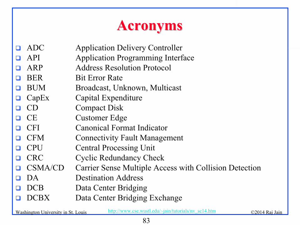
AcronymsAcronyms
ADC
Application Delivery Controller
API
Application Programming Interface
ARP
Address Resolution Protocol
BER
Bit Error Rate
BUM
Broadcast, Unknown, Multicast
CapEx
Capital Expenditure
CD
Compact Disk
CE
Customer Edge
CFI
Canonical Format Indicator
CFM
Connectivity Fault Management
CPU
Central Processing Unit
CRC
Cyclic Redundancy Check
CSMA/CD
Carrier Sense Multiple Access with Collision Detection
DA
Destination Address
DCB
Data Center Bridging
DCBX
Data Center Bridging Exchange
84©2014 Raj Jainhttp://www.cse.wustl.edu/~jain/tutorials/nv_sc14.htmWashington University in St. Louis
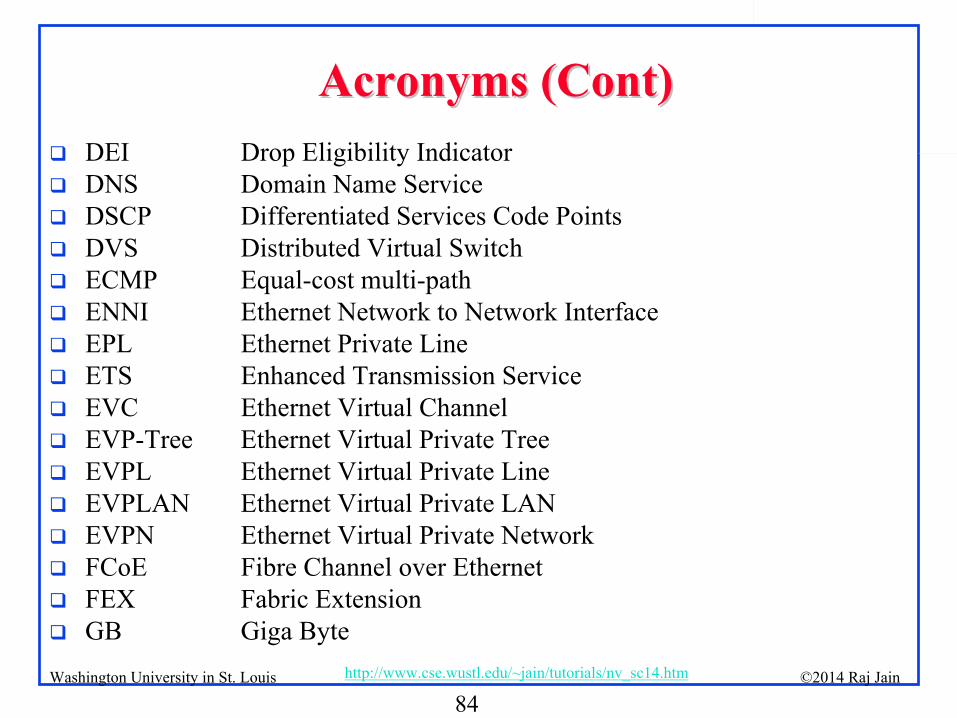
Acronyms (Cont) Acronyms (Cont)
DEI
Drop Eligibility Indicator
DNS
Domain Name Service
DSCP
Differentiated Services Code Points
DVS
Distributed Virtual Switch
ECMP
Equal-cost multi-path
ENNI
Ethernet Network to Network Interface
EPL
Ethernet Private Line
ETS
Enhanced Transmission Service
EVC
Ethernet Virtual Channel
EVP-Tree
Ethernet Virtual Private Tree
EVPL
Ethernet Virtual Private Line
EVPLAN
Ethernet Virtual Private LAN
EVPN
Ethernet Virtual Private Network
FCoE
Fibre Channel over Ethernet
FEX
Fabric Extension
GB
Giga Byte
85©2014 Raj Jainhttp://www.cse.wustl.edu/~jain/tutorials/nv_sc14.htmWashington University in St. Louis
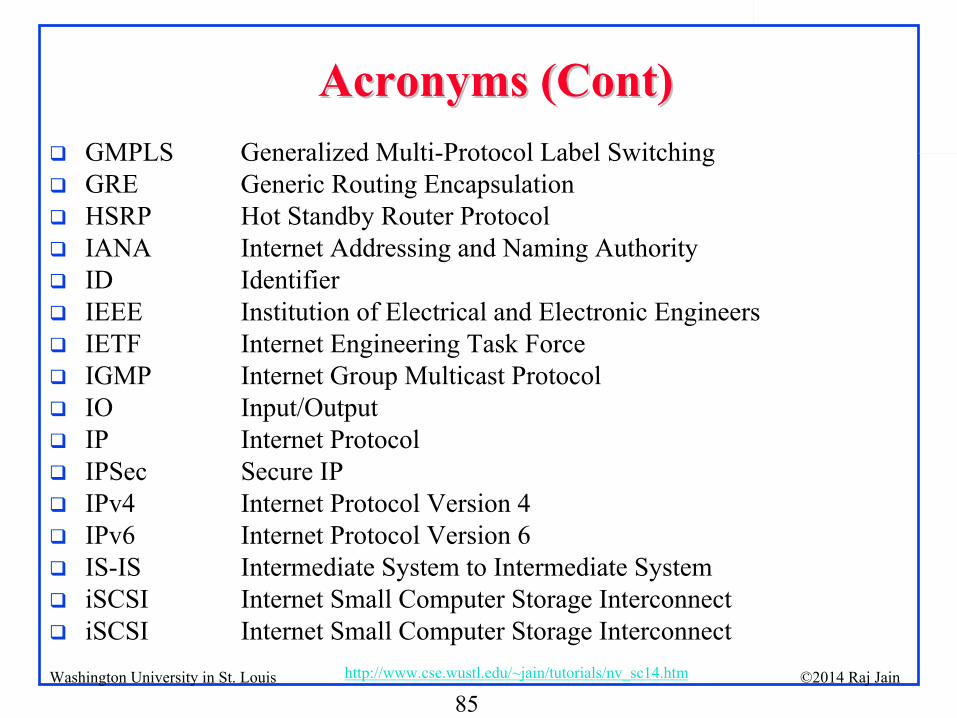
Acronyms (Cont) Acronyms (Cont)
GMPLS
Generalized Multi-Protocol Label Switching
GRE
Generic Routing Encapsulation
HSRP
Hot Standby Router Protocol
IANA
Internet Addressing and Naming Authority
ID
Identifier
IEEE
Institution of Electrical and Electronic Engineers
IETF
Internet Engineering Task Force
IGMP
Internet Group Multicast Protocol
IO
Input/Output
IP
Internet Protocol
IPSec
Secure IP
IPv4
Internet Protocol Version 4
IPv6
Internet Protocol Version 6
IS-IS
Intermediate System to Intermediate System
iSCSI
Internet Small Computer Storage Interconnect
iSCSI
Internet Small Computer Storage Interconnect
86©2014 Raj Jainhttp://www.cse.wustl.edu/~jain/tutorials/nv_sc14.htmWashington University in St. Louis
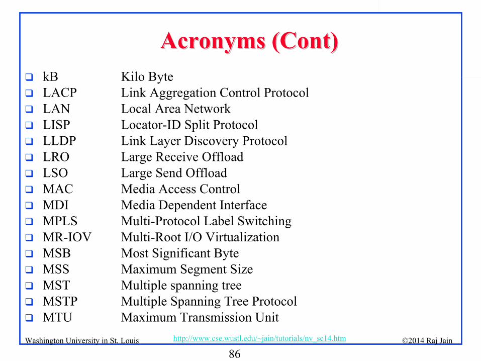
Acronyms (Cont) Acronyms (Cont)
kB
Kilo Byte
LACP
Link Aggregation Control Protocol
LAN
Local Area Network
LISP
Locator-ID Split Protocol
LLDP
Link Layer Discovery Protocol
LRO
Large Receive Offload
LSO
Large Send Offload
MAC
Media Access Control
MDI
Media Dependent Interface
MPLS
Multi-Protocol Label Switching
MR-IOV
Multi-Root I/O Virtualization
MSB
Most Significant Byte
MSS
Maximum Segment Size
MST
Multiple spanning tree
MSTP
Multiple Spanning Tree Protocol
MTU
Maximum Transmission Unit
87©2014 Raj Jainhttp://www.cse.wustl.edu/~jain/tutorials/nv_sc14.htmWashington University in St. Louis
Acronyms (Cont) Acronyms (Cont)
MVGRE
Network Virtualization Using GRE
NIC
Network Interface Card
NNI
Network-to-Network Interface
NVO3
Network Virtualization Overlay using L3
OAM
Operation, Administration, and Management
OpEx
Operation Expenses
OSPF
Open Shortest Path First
OTV
Overlay Transport Virtualization
PB
Provider Bridge
PBB-TE
Provider Backbone Bridge with Traffic Engineering
PBB
Provider Backbone Bridge
PBEB
Provider Backbone Edge Bridge
PCI-SIG
PCI Special Interest Group
PCI
Peripheral Component Interconnect
PCIe
PCI Express
PCP
Priority Code Point
88©2014 Raj Jainhttp://www.cse.wustl.edu/~jain/tutorials/nv_sc14.htmWashington University in St. Louis
Acronyms (Cont) Acronyms (Cont)
PE
Provider Edge
PF
Physical Function
PFC
Priority-based Flow Control
PHY
Physical Layer
pM
Physical Machine
pNIC
Physical Network Interface Card
PPP
Point-to-Point Protocol
pSwitch
Physical Switch
PW
Pseudo wire
PWoGRE
Pseudo wire over Generic Routing Encapsulation
PWoMPLS
Pseudo wire over Multi Protocol Label Switching
QCN
Quantized Congestion Notification
QoS
Quality of Service
RAID
Redundant Array of Independent Disks
RBridge
Routing Bridge
RFC
Request for Comments
89©2014 Raj Jainhttp://www.cse.wustl.edu/~jain/tutorials/nv_sc14.htmWashington University in St. Louis
Acronyms (Cont) Acronyms (Cont)
RSTP
Rapid Spanning Tree Protocol
SA
Source Address
SDH
Synchronous Digital Hierarchy
SID
Service Identifier
SNIA
Storage Network Industry Association
SONET
Synchronous Optical Network
SPB
Shortest Path Bridging
SR-IOV
Single Root I/O Virtualization
STP
Spanning Tree Protocol
STT
Stateless Transport Tunneling Protocol
TCP
Transmission Control Protocol
TE
Traffic Engineering
TLV
Type-Length-Value
TP
Transport Protocol
TPI
Tag Protocol Identifier
TRILL
Transparent Interconnection of Lots of Links
90©2014 Raj Jainhttp://www.cse.wustl.edu/~jain/tutorials/nv_sc14.htmWashington University in St. Louis
Acronyms (Cont) Acronyms (Cont)
TV
Television
UCA
Use Customer Address
UDP
User Datagram Protocol
UNI
User Network Interface
VBE
Virtual Bridge Port Extension
VDC
Virtual Device Contexts
VEB
Virtual Edge Bridge
VEM
Virtual Ethernet Module
VEPA
Virtual Ethernet Port Aggregator
VF
Virtual Function
VID
VLAN ID
VLAN
Virtual LAN
VM
Virtual Machine
VNI
Virtual Network ID
vNIC
Virtual Network Interface Card
VoD
Video on Demand
91©2014 Raj Jainhttp://www.cse.wustl.edu/~jain/tutorials/nv_sc14.htmWashington University in St. Louis
Acronyms (Cont) Acronyms (Cont)
VOIP
Voice over IP
vPC
Virtual Port Channels
VPLS
Virtual Private LAN Service
VPN
Virtual Private Network
VRF
Virtual Routing and Forwarding
VRRP
Virtual Router Redundancy Protocol
VSID
Virtual Subnet Identifier
VSM
Virtual Switch Module
VSS
Virtual Switch System
vSwitch
Virtual Switch
VTEP
Virtual Tunnel End Point
VXLAN
Virtual Extensible LAN