Embed Size (px)
Citation preview
Proteus: Visual Analogy in Problem Solving
Jim Davies a Ashok K. Goel b Patrick W. Yaner b
aSchool of ComputingQueen’s University; Kingston, ON, K7L 3N6 Canada
bCollege of ComputingGeorgia Institute of Technology Atlanta, GA 30332 USA
Abstract
This work examines the hypothesis that visual knowledge alone is sufficient foranalogical transfer of problem-solving procedures. It develops a computational the-ory of visual analogy in problem solving which has been implemented in a computerprogram called Proteus. Proteus provides two main things. Firstly, it provides acontent account for visual analogy in problem solving, along with a correspondingvocabulary and data structures for representing the knowledge content. Secondly,Proteus provides a process account for visual analogy in problem solving, alongwith corresponding methods and algorithms. Proteus addresses all major subtasksof analogy. It also identifies a new subtask in the task stucture of analogical problemsolving: dynamic generation of new mappings between the intermediate knowledgestates in the source and the target cases when a step in the transferred procedurecreates a new object. Finally, by examining the limitations of use of visual knowledgealone, Proteus helps identify the functional roles of (non-visual) causal knowledgein analogical problem solving.
Key words: analogy, visual reasoning, visual knowledge, problem-solving,case-based reasoning, diagrammatic reasoning, diagrams
1 Introduction
Visual analogy is a topic of longstanding and growing interest in AI. Evans’early ANALOGY program solved multiple choice geometric analogy problemsof the kind found on many intelligence tests [9]. Figure 1 illustrates this kind
Email addresses: [email protected] (Jim Davies), [email protected](Ashok K. Goel), [email protected] (Patrick W. Yaner).
Preprint submitted to Artificial Intelligence November 2005
5
A C
?
B
1 2 3 4
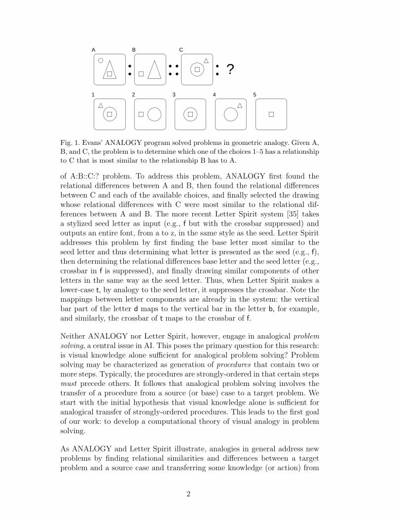
Fig. 1. Evans’ ANALOGY program solved problems in geometric analogy. Given A,B, and C, the problem is to determine which one of the choices 1–5 has a relationshipto C that is most similar to the relationship B has to A.
of A:B::C:? problem. To address this problem, ANALOGY first found therelational differences between A and B, then found the relational differencesbetween C and each of the available choices, and finally selected the drawingwhose relational differences with C were most similar to the relational dif-ferences between A and B. The more recent Letter Spirit system [35] takesa stylized seed letter as input (e.g., f but with the crossbar suppressed) andoutputs an entire font, from a to z, in the same style as the seed. Letter Spiritaddresses this problem by first finding the base letter most similar to theseed letter and thus determining what letter is presented as the seed (e.g., f),then determining the relational differences base letter and the seed letter (e.g.,crossbar in f is suppressed), and finally drawing similar components of otherletters in the same way as the seed letter. Thus, when Letter Spirit makes alower-case t, by analogy to the seed letter, it suppresses the crossbar. Note themappings between letter components are already in the system: the verticalbar part of the letter d maps to the vertical bar in the letter b, for example,and similarly, the crossbar of t maps to the crossbar of f.
Neither ANALOGY nor Letter Spirit, however, engage in analogical problemsolving, a central issue in AI. This poses the primary question for this research:is visual knowledge alone sufficient for analogical problem solving? Problemsolving may be characterized as generation of procedures that contain two ormore steps. Typically, the procedures are strongly-ordered in that certain stepsmust precede others. It follows that analogical problem solving involves thetransfer of a procedure from a source (or base) case to a target problem. Westart with the initial hypothesis that visual knowledge alone is sufficient foranalogical transfer of strongly-ordered procedures. This leads to the first goalof our work: to develop a computational theory of visual analogy in problemsolving.
As ANALOGY and Letter Spirit illustrate, analogies in general address newproblems by finding relational similarities and differences between a targetproblem and a source case and transferring some knowledge (or action) from
2
the source to the target. In general, analogy involves several subtasks includingretrieving from memory the source case most similar to the target problem,mapping (or aligning) the the elements of target and the source, transferringknowledge from the source to the target, evaluating what was transferred inthe context of the target, and storing the target in memory. These tasks maythemselves involve additional subtasks. For example, the retrieval task maybe decomposed into the subtasks of reminding and selection, and the transfertask may involve the subtask of adaptation. ANALOGY addresses only themapping and transfer subtasks of analogy. In contrast, Letter Spirit addressesonly the retrieval, transfer and evaluation subtasks (since the mappings be-tween different letters are already stored in the system). A second goal of ourwork is to build a unified theory of visual analogy that not only addresses allmajor subtasks of analogy, but also uses a uniform knowledge representationfor all the subtasks.
Also as illustrated by ANALOGY and Letter Spirit, visual analogy refers toanalogy based only on the appearance of a situation. e.g., the shape of the letterf and the spatial relationship between its components. Causal and functionalknowledge is either not present or is (at most) implicit. Thus, in visual analogy,knowledge states in source cases and target problems are characterized byshapes of objects (e.g., a line, a semi-circle, etc.), and spatial relations amongthe objects or their components (e.g., above, left-of, contained-in, etc.). BothANALOGY and Letter Spirit describe a content account of shapes and spatialrelations in their respective domains. Our work similarly describes a contentaccount of shapes and spatial relations for visual analogy in problem solving,and provides a vocabulary and data structures for representing the content.
In addition, both ANALOGY and Letter Spirit provide a process accountfor their respective tasks. Their process account is articulated in terms oftheir task decompositions, methods for accomplishing specific tasks in thetask structure, and algorithms corresponding to the methods. Our work simi-larly provides a process account for visual analogy in problem solving in termsof task structures, methods and algorithms. A significant finding of our work isthat if and when a step in the problem-solving procedure being tranferred froma source case to a target problem creates new objects, then the analogical pro-cess needs to dynamically generate a new mapping between the correspondingintermediate states in the source case and the target problem.
The Proteus system is an implementation of our computational theory of vi-sual analogy in problem solving. Proteus addresses all major subtasks of ana-logical problem solving. However, since visual representations do not capture(non-visual) causal and functional knowledge, the mapping task, as we will de-scribe in detail below, generates multiple initial mappings between a retrievedsource case and the target problem. Further, since the evaluation subtask ap-pears to require causal and functional knowledge, and since causality is (at
3
AnalogicalReasoning
Visual Reasoning
Problem Sovling
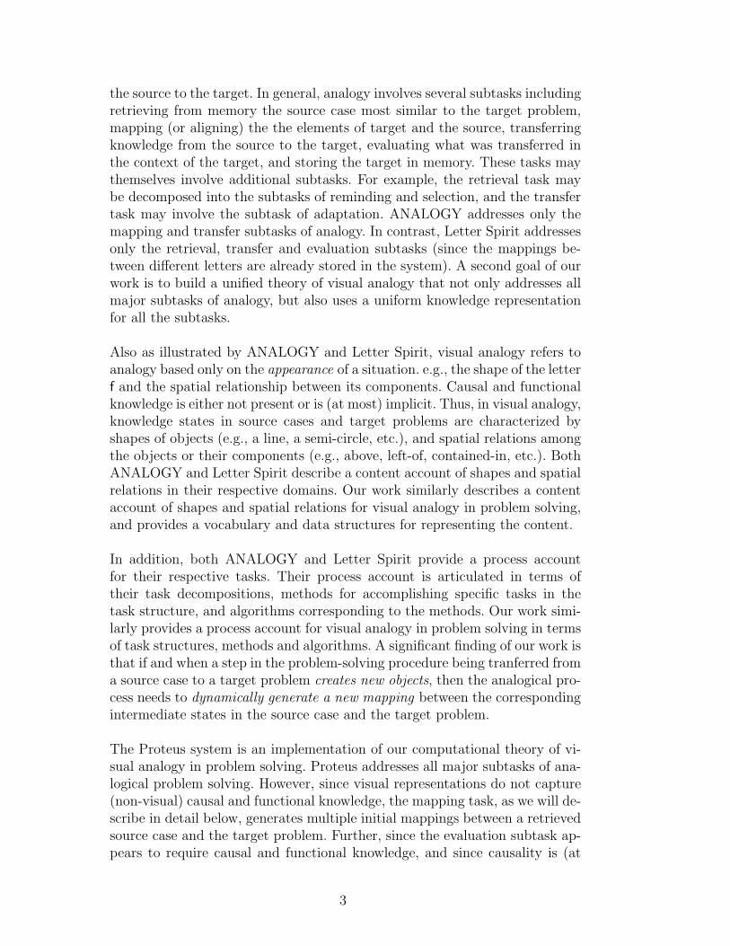
Fig. 2. At the task level, Proteus is a theory of problem solving. At the level of meth-ods, it uses analogical reasoning to solve problems. In terms of types of knowledge,it uses only visual knowledge for making analogies.
most) only implicit in visual representations, Proteus does not automate theevaluation task with visual reasoning. By examining the limitations of use ofvisual knowledge alone, Proteus helps identify the necessary functional rolesof causal knowledge in analogical problem solving.
2 Proteus
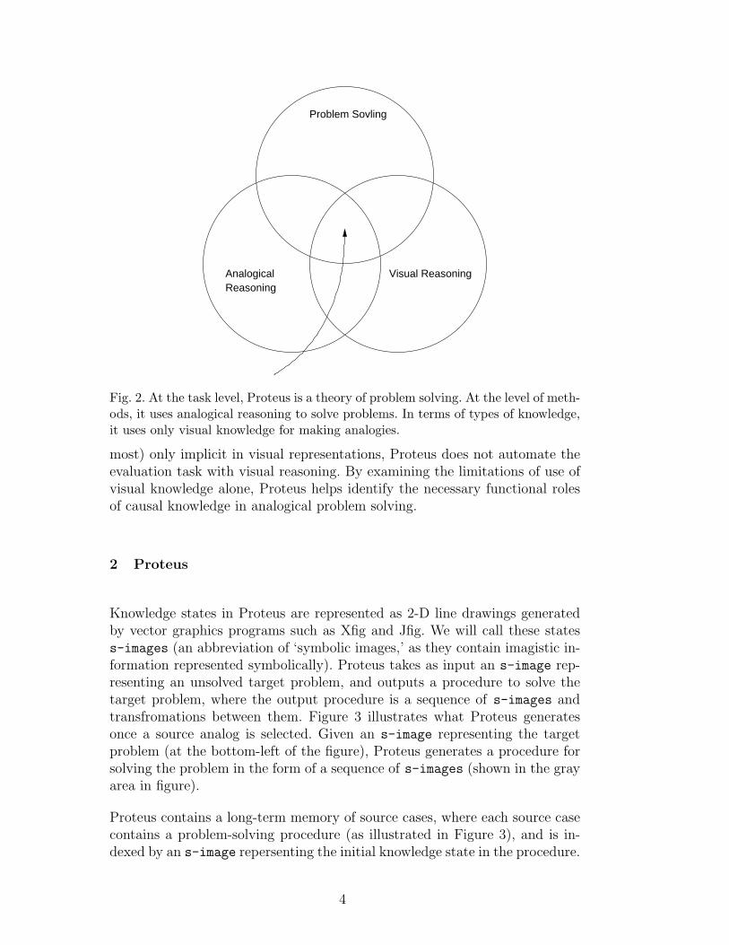
Knowledge states in Proteus are represented as 2-D line drawings generatedby vector graphics programs such as Xfig and Jfig. We will call these statess-images (an abbreviation of ‘symbolic images,’ as they contain imagistic in-formation represented symbolically). Proteus takes as input an s-image rep-resenting an unsolved target problem, and outputs a procedure to solve thetarget problem, where the output procedure is a sequence of s-images andtransfromations between them. Figure 3 illustrates what Proteus generatesonce a source analog is selected. Given an s-image representing the targetproblem (at the bottom-left of the figure), Proteus generates a procedure forsolving the problem in the form of a sequence of s-images (shown in the grayarea in figure).
Proteus contains a long-term memory of source cases, where each source casecontains a problem-solving procedure (as illustrated in Figure 3), and is in-dexed by an s-image repersenting the initial knowledge state in the procedure.
4
Output by reasoner
Source
Target
mapping
Source Simage 1
mapping
Source Simage 2 Source Simage n
Target Simage 1 Target Simage 2 Target Simage n
mapping
Fig. 3. This figure illustrates the input and output to Proteus’ transfer in the ab-stract. The input is an s-image representing the target problem (shown at thebottom left). The output is a procedure represented as a sequence of s-images(shown in the gray area at the bottom-right of the figure). Proteus generates theprocedure by transferring a procedure from a source case (shown at the top of thefigure). In the process, it retrieves source cases, generates mappings between thetarget problem and the source case as indicated in the figure, and so on.
Proteus solves an input target problem by executing the five major subtasksof analogy. The first task is retrieval, in which the target problem, representedby a single s-image, is used as a query into the case base. If the retrievaltask outputs multiple source cases, then Proteus selects one for further pro-cessing. The second subtask is mapping (as indicated in Figure 3), in whichthe elements (i.e., objects, relations) of s-image representing the target prob-lem are matched with corresponding elements in the s-image with which thesource case is indexed. The output of the mapping task is a series of maps,each linking an element in the source to an element in the target. The thirdsubtask is transfer. Proteus transfers the steps in the procedure in the sourceto the target problem one step at a time. The transfer task may also involveadaptation of some elements in the source case. The fourth step is evaluation.Proteus presently uses precompiled knowledge for evaluating the solution tothe target problem, as described below. If the evaluation fails, then it goesback to the output of the retrieval task, and selects a different source case forprocessing.
2.1 An Illustrative Example
We will use the classic fortress/tumor problem [8] as the running examplethroughout this paper. In this problem, a general must overthrow a dictatorin a fortress. His army is poised to attack along one of many roads leading tothe fortress when the general finds that the roads are mined such that largegroups passing will set them off. To solve the problem, the general breaks thearmy into smaller groups, which take different roads simultaneously, arrivingtogether at the fortress. In the unsolved target problem there is a tumor thatmust be destroyed with a ray of radiation, but the ray will destroy healthy
5
s−image2
decompose
decompose
left−road1
road1top−
Output by Galatea
s−image3
s−image2 s−image3
s−image1
s−image1
map
road1right−
map
map
map
map
mapping mapping mapping
to−set
move−
move−
to−set
right−body1tumor1
left−body1
body1top−
tumor2 tumor3
fortress1 fortress3fortress2
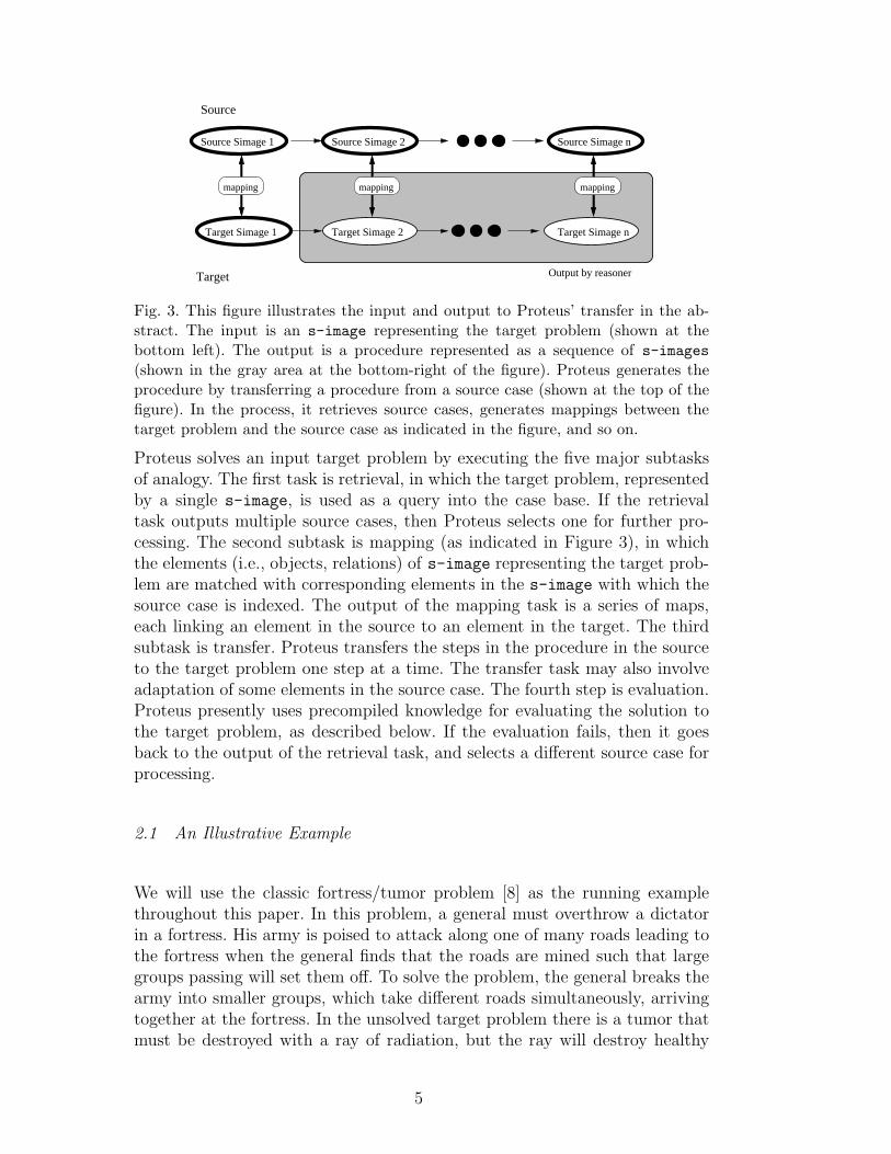
Fig. 4. This figure illustrates the input and output of the transfer stage in Proteusfor the fortress/tumor problem. The input is an s-image representing the targettumor problem (shown at the bottom left). The output is a procedure representedas a sequence of s-images (shown in the gray area at the bottom-right of thefigure). Proteus generates the procedure by transferring a procedure from the sourcefortress case (shown at the top of the figure). In the process, it retrieves source cases,generates mappings between the target problem and the source case as indicated inthe figure, and so on.
tissue on the way in, killing the patient. The analogous solution is to haveseveral weaker rays simultaneously converging on the tumor to destroy it.Figure 4 illustrates Proteus’ task for the fortress/tumor problem.
2.2 Knowledge Representation
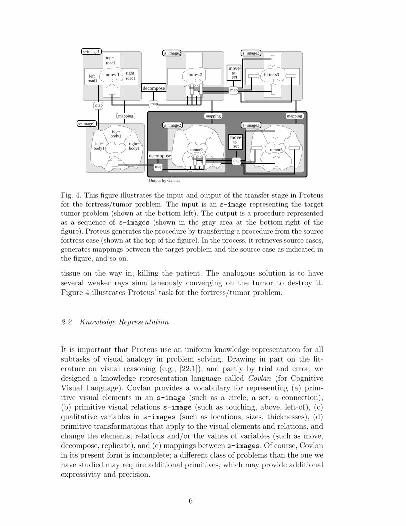
It is important that Proteus use an uniform knowledge representation for allsubtasks of visual analogy in problem solving. Drawing in part on the lit-erature on visual reasoning (e.g., [22,1]), and partly by trial and error, wedesigned a knowledge representation language called Covlan (for CognitiveVisual Language). Covlan provides a vocabulary for representing (a) prim-itive visual elements in an s-image (such as a circle, a set, a connection),(b) primitive visual relations s-image (such as touching, above, left-of), (c)qualitative variables in s-images (such as locations, sizes, thicknesses), (d)primitive transformations that apply to the visual elements and relations, andchange the elements, relations and/or the values of variables (such as move,decompose, replicate), and (e) mappings between s-images. Of course, Covlanin its present form is incomplete; a different class of problems than the one wehave studied may require additional primitives, which may provide additionalexpressivity and precision.
6
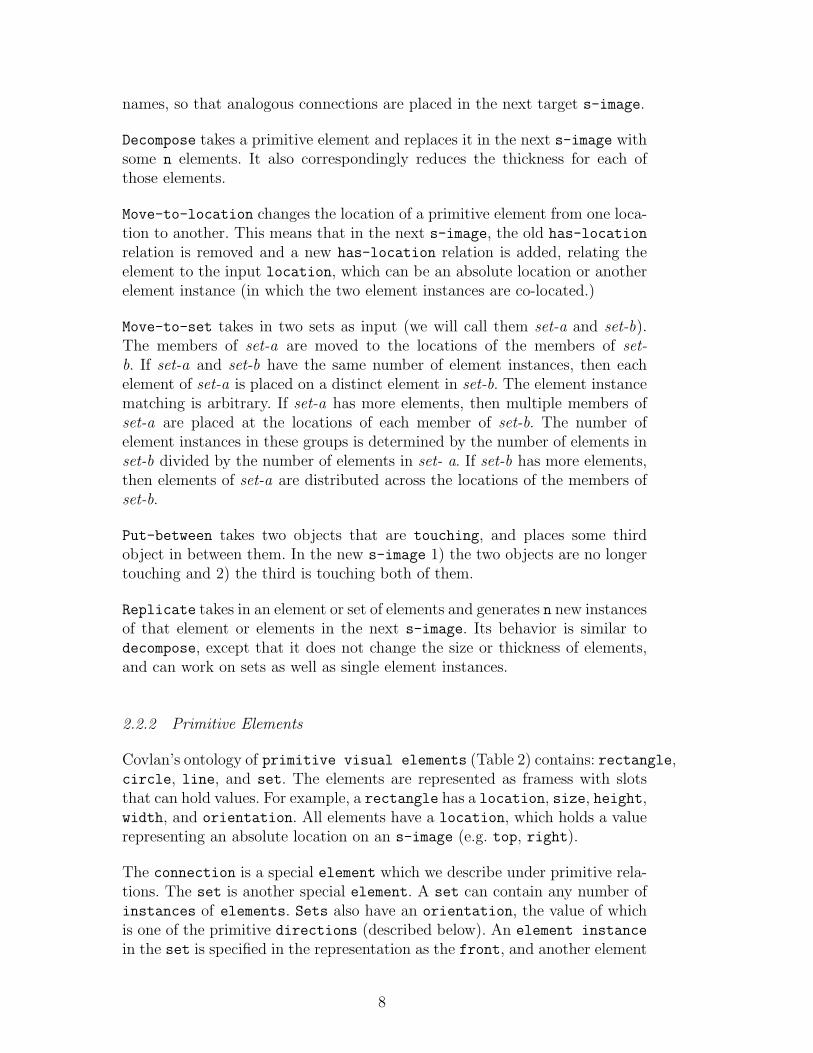
Primitive Visual Transformations
Transformation name arguments
add-element object-type, location (optional)
add-connections connection/connection-set
decompose object, number-of-resultants, type
move-to-location object, new-location
move-to-set object, object2
put-between object, object2, object3
replicate object, number-of-resultantsTable 1Primitive transformations.
looks−like
SIMAGE−2
has−component
has−location TOPCIRCLE NEW−OBJECT−4123
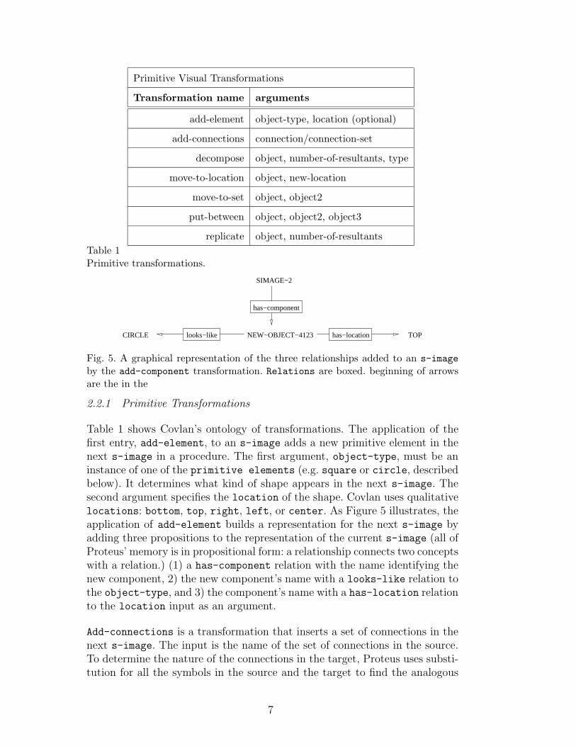
Fig. 5. A graphical representation of the three relationships added to an s-imageby the add-component transformation. Relations are boxed. beginning of arrowsare the in the
2.2.1 Primitive Transformations
Table 1 shows Covlan’s ontology of transformations. The application of thefirst entry, add-element, to an s-image adds a new primitive element in thenext s-image in a procedure. The first argument, object-type, must be aninstance of one of the primitive elements (e.g. square or circle, describedbelow). It determines what kind of shape appears in the next s-image. Thesecond argument specifies the location of the shape. Covlan uses qualitativelocations: bottom, top, right, left, or center. As Figure 5 illustrates, theapplication of add-element builds a representation for the next s-image byadding three propositions to the representation of the current s-image (all ofProteus’ memory is in propositional form: a relationship connects two conceptswith a relation.) (1) a has-component relation with the name identifying thenew component, 2) the new component’s name with a looks-like relation tothe object-type, and 3) the component’s name with a has-location relationto the location input as an argument.
Add-connections is a transformation that inserts a set of connections in thenext s-image. The input is the name of the set of connections in the source.To determine the nature of the connections in the target, Proteus uses substi-tution for all the symbols in the source and the target to find the analogous
7
names, so that analogous connections are placed in the next target s-image.
Decompose takes a primitive element and replaces it in the next s-image withsome n elements. It also correspondingly reduces the thickness for each ofthose elements.
Move-to-location changes the location of a primitive element from one loca-tion to another. This means that in the next s-image, the old has-location
relation is removed and a new has-location relation is added, relating theelement to the input location, which can be an absolute location or anotherelement instance (in which the two element instances are co-located.)
Move-to-set takes in two sets as input (we will call them set-a and set-b).The members of set-a are moved to the locations of the members of set-b. If set-a and set-b have the same number of element instances, then eachelement of set-a is placed on a distinct element in set-b. The element instancematching is arbitrary. If set-a has more elements, then multiple members ofset-a are placed at the locations of each member of set-b. The number ofelement instances in these groups is determined by the number of elements inset-b divided by the number of elements in set- a. If set-b has more elements,then elements of set-a are distributed across the locations of the members ofset-b.
Put-between takes two objects that are touching, and places some thirdobject in between them. In the new s-image 1) the two objects are no longertouching and 2) the third is touching both of them.
Replicate takes in an element or set of elements and generates n new instancesof that element or elements in the next s-image. Its behavior is similar todecompose, except that it does not change the size or thickness of elements,and can work on sets as well as single element instances.
2.2.2 Primitive Elements
Covlan’s ontology of primitive visual elements (Table 2) contains: rectangle,circle, line, and set. The elements are represented as framess with slotsthat can hold values. For example, a rectangle has a location, size, height,width, and orientation. All elements have a location, which holds a valuerepresenting an absolute location on an s-image (e.g. top, right).
The connection is a special element which we describe under primitive rela-tions. The set is another special element. A set can contain any number ofinstances of elements. Sets also have an orientation, the value of whichis one of the primitive directions (described below). An element instance
in the set is specified in the representation as the front, and another element
8
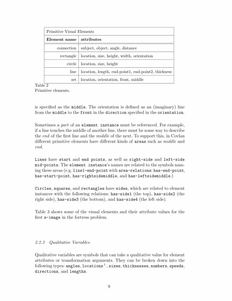
Primitive Visual Elements
Element name attributes
connection subject, object, angle, distance
rectangle location, size, height, width, orientation
circle location, size, height
line location, length, end-point1, end-point2, thickness
set location, orientation, front, middleTable 2Primitive elements.
is specified as the middle. The orientation is defined as an (imaginary) linefrom the middle to the front in the direction specified in the orientation.
Sometimes a part of an element instance must be referenced. For example,if a line touches the middle of another line, there must be some way to describethe end of the first line and the middle of the next. To support this, in Covlandifferent primitive elements have different kinds of areas such as middle andend.
Lines have start and end points, as well as right-side and left-side
mid-points. The element instance’s names are related to the symbols nam-ing these areas (e.g. line1-end-point with area-relations: has-end-point,has-start-point, has-rightsidemiddle, and has-leftsidemiddle.)
Circles, squares, and rectangles have sides, which are related to elementinstances with the following relations: has-side1 (the top), has-side2 (theright side), has-side3 (the bottom), and has-side4 (the left side).
Table 3 shows some of the visual elements and their attribute values for thefirst s-image in the fortress problem.
2.2.3 Qualitative Variables
Qualitative variables are symbols that can take a qualitative value for elementattributes or transformation arguments. They can be broken down into thefollowing types: angles, locations 1 , sizes, thicknesses, numbers, speeds,directions, and lengths.
9
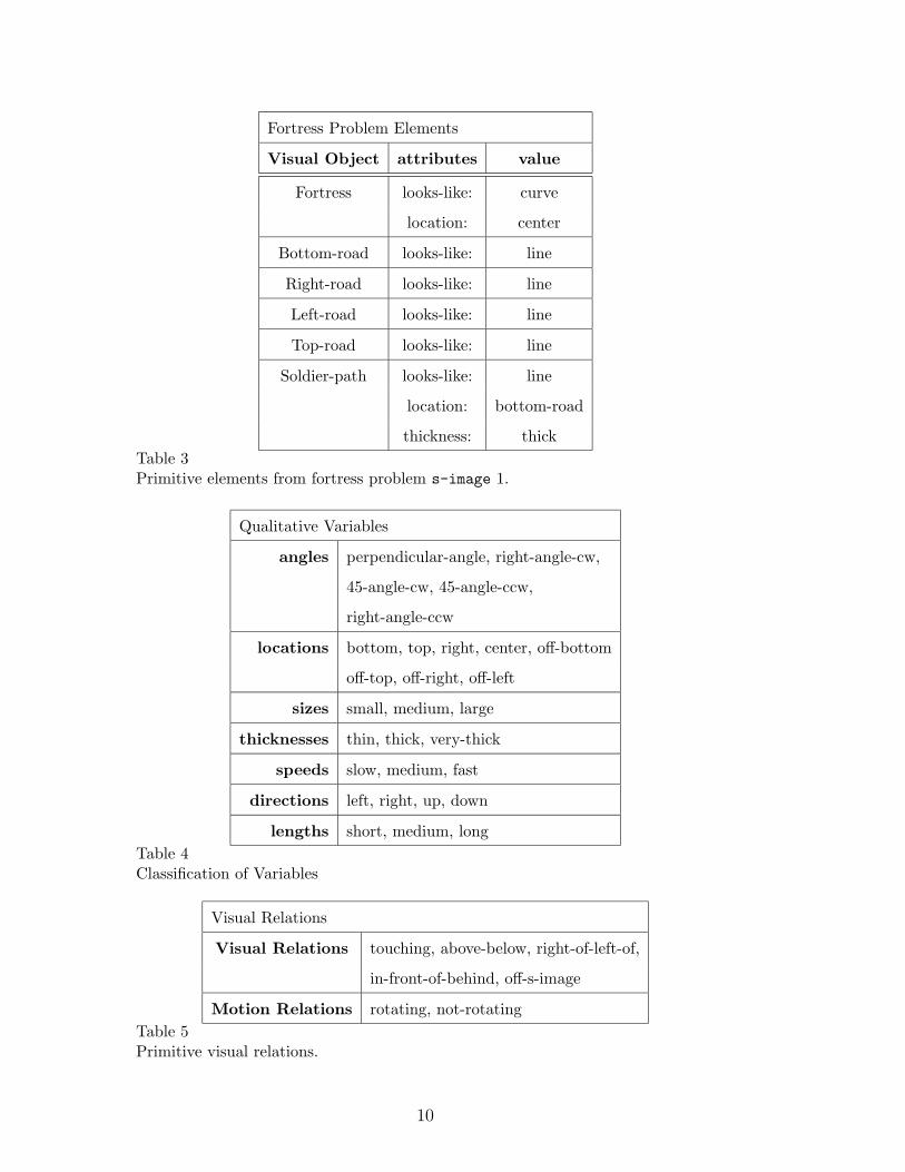
Fortress Problem Elements
Visual Object attributes value
Fortress looks-like: curve
location: center
Bottom-road looks-like: line
Right-road looks-like: line
Left-road looks-like: line
Top-road looks-like: line
Soldier-path looks-like: line
location: bottom-road
thickness: thickTable 3Primitive elements from fortress problem s-image 1.
Qualitative Variables
angles perpendicular-angle, right-angle-cw,
45-angle-cw, 45-angle-ccw,
right-angle-ccw
locations bottom, top, right, center, off-bottom
off-top, off-right, off-left
sizes small, medium, large
thicknesses thin, thick, very-thick
speeds slow, medium, fast
directions left, right, up, down
lengths short, medium, longTable 4Classification of Variables
Visual Relations
Visual Relations touching, above-below, right-of-left-of,
in-front-of-behind, off-s-image
Motion Relations rotating, not-rotatingTable 5Primitive visual relations.
10
has−angle
has−distance
square1
square2
square1−−square2−−connection1
short−distance
right−angle−cw
is−subject−for−connection
is−object−for−connection
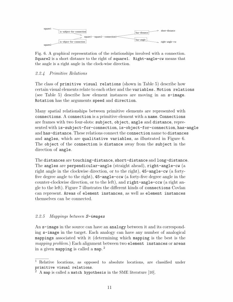
Fig. 6. A graphical representation of the relationships involved with a connection.Square2 is a short distance to the right of square1. Right-angle-cw means thatthe angle is a right angle in the clock-wise direction.
2.2.4 Primitive Relations
The class of primitive visual relations (shown in Table 5) describe howcertain visual elements relate to each other and the variables. Motion relations
(see Table 5) describe how element instances are moving in an s-image.Rotation has the arguments speed and direction.
Many spatial relationships between primitive elements are represented withconnections. A connection is a primitive element with a name. Connectionsare frames with two four-slots: subject, object, angle and distance, repre-sented with is-subject-for-connection, is-object-for-connection, has-angleand has-distance. These relations connect the connection name to distancesand angles, which are qualitative variables, as illustrated in Figure 6.The object of the connection is distance away from the subject in thedirection of angle.
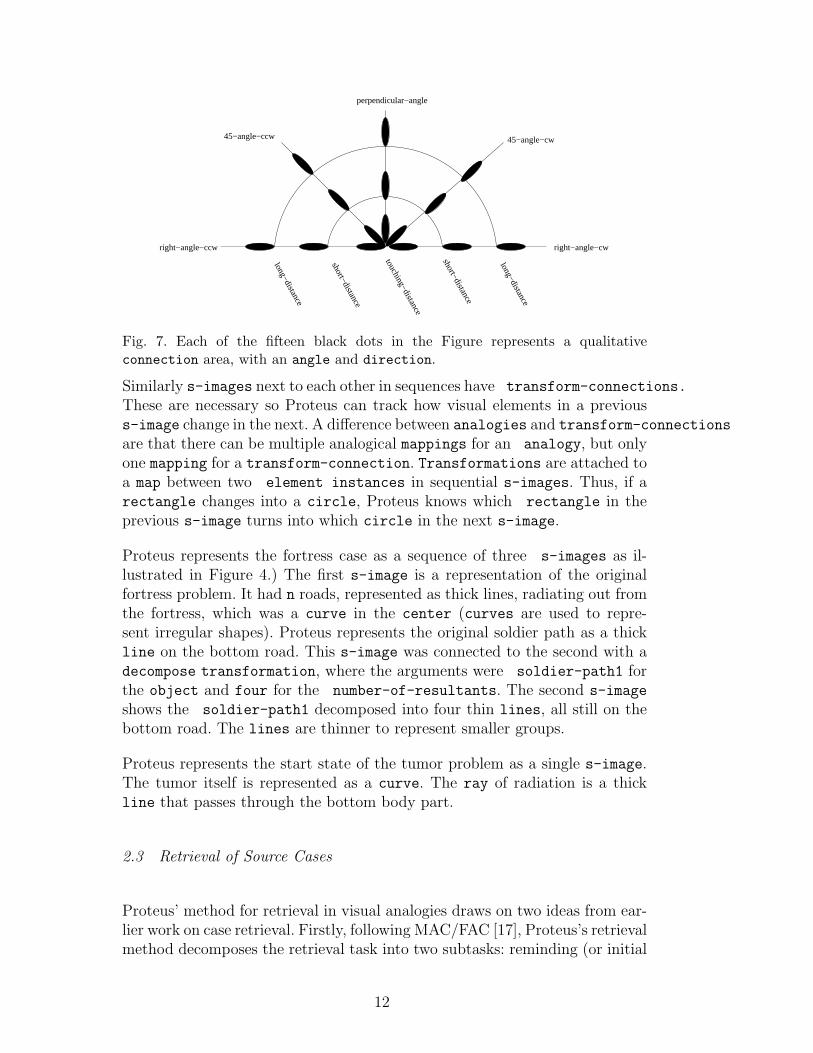
The distances are touching-distance, short-distance and long-distance.The angles are perpendicular-angle (straight ahead), right-angle-cw (aright angle in the clockwise direction, or to the right), 45-angle-cw (a forty-five degree angle to the right), 45-angle-ccw (a forty-five degree angle in thecounter-clockwise direction, or to the left), and right-angle-ccw (a right an-gle to the left). Figure 7 illustrates the different kinds of connections Covlancan represent. Areas of element instances, as well as element instances
themselves can be connected.
2.2.5 Mappings between S-images
An s-image in the source can have an analogy between it and its correspond-ing s-image in the target. Each analogy can have any number of analogicalmappings associated with it (determining which mapping is the best is themapping problem.) Each alignment between two element instances or areasin a given mapping is called a map. 2
1 Relative locations, as opposed to absolute locations, are classified underprimitive visual relations.2 A map is called a match hypothesis in the SME literature [10].
11
touching−distance
short−distance
short−distance
long−distance
long−distance
right−angle−cwright−angle−ccw
45−angle−ccw
perpendicular−angle
45−angle−cw
Fig. 7. Each of the fifteen black dots in the Figure represents a qualitativeconnection area, with an angle and direction.
Similarly s-images next to each other in sequences have transform-connections.
These are necessary so Proteus can track how visual elements in a previouss-image change in the next. A difference between analogies and transform-connections
are that there can be multiple analogical mappings for an analogy, but onlyone mapping for a transform-connection. Transformations are attached toa map between two element instances in sequential s-images. Thus, if arectangle changes into a circle, Proteus knows which rectangle in theprevious s-image turns into which circle in the next s-image.
Proteus represents the fortress case as a sequence of three s-images as il-lustrated in Figure 4.) The first s-image is a representation of the originalfortress problem. It had n roads, represented as thick lines, radiating out fromthe fortress, which was a curve in the center (curves are used to repre-sent irregular shapes). Proteus represents the original soldier path as a thickline on the bottom road. This s-image was connected to the second with adecompose transformation, where the arguments were soldier-path1 forthe object and four for the number-of-resultants. The second s-image
shows the soldier-path1 decomposed into four thin lines, all still on thebottom road. The lines are thinner to represent smaller groups.
Proteus represents the start state of the tumor problem as a single s-image.The tumor itself is represented as a curve. The ray of radiation is a thickline that passes through the bottom body part.
2.3 Retrieval of Source Cases
Proteus’ method for retrieval in visual analogies draws on two ideas from ear-lier work on case retrieval. Firstly, following MAC/FAC [17], Proteus’s retrievalmethod decomposes the retrieval task into two subtasks: reminding (or initial
12
recall), and selection. Secondly, following ACME [29], Proteus views case re-trieval as a constraint satisfaction problem. Note that while MAC/FAC usesstructure-mapping [10] for the selecton task, ACME uses a relaxation pro-cedure based on spreading-activation for the retrieval and mapping task asa whole, though there is a complementary system called ARCS [39] whichemploys much the same method for retrieval by weakening the structural con-straints. In contrast, Proteus uses feature vector matching as the method forthe first task of reminding, and constraint satisfaction with backtracking forthe second task of selection.
The retrieval task is essentially one of matching objects (variables and con-stants) in the target and the source under the constraints imposed by thepropositions in which they appear. An s-image can be viewed as a networkof relationships between visual elements, and so we can view the element
instances of the target s-image as variables, whose potential values areelement instances of all the source s-images in memory, and the linksbetween element instances in the target we can view as constraints thatmust hold between the variables. Thus, each proposition imposes a constraintbetween two variables in the s-image.
Treating the element-instances in the target as variables to be assigned val-ues, the potential values are the element instances from the s-image de-scriptions in memory, all of which are considered at once. That is, the methodis not performing a separate test on each potential source in memory, but,rather, it is running a search procedure on the entire memory considered col-lectively. The constraints on the values assigned to the variables (the targetelements) are precisely those imposed by the subgraph isomorphism prob-lem: if elements A and B from the target are to be matched with elements
X and Y from memory, respectively, then, first, X and Y must be in thesame s-image; second, all relations that hold between A and B must alsohold between X and Y , respectively. If these constraints are met, then A canbe matched with X and B can be matched with Y . Here, the constraints arebinary (say, A is left of B—a relational constraint). The only exception is theconstraint that all values be from the same s-image, but this can be inferredfrom the binary constraints.
2.3.1 Retrieval and Matching Process
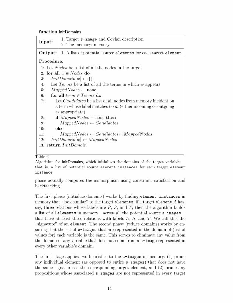
The matching process works in three phases: initialization of domains, reduc-tion of domains, and finding the matching, where matching means subgraphisomorphism. The first phase initializes the target domains to sets of valuesthat are involved in the same kinds of relations. The second phase reducesthese domains by eliminating values that are not all in the same s-image.These two phases reduce the selection of values for each variable. The third
13
function InitDomains
Input:1. Target s-image and Covlan description2. The memory: memory
Output: 1. A list of potential source elements for each target element
Procedure:
1: Let Nodes be a list of all the nodes in the target2: for all w ∈ Nodes do3: InitDomain[w]← {}4: Let Terms be a list of all the terms in which w appears5: MappedNodes← none6: for all term ∈ Terms do7: Let Candidates be a list of all nodes from memory incident on
a term whose label matches term (either incoming or outgoingas appropriate)
8: if MappedNodes = none then9: MappedNodes← Candidates
10: else11: MappedNodes← Candidates ∩MappedNodes12: InitDomain[w]←MappedNodes13: return InitDomain
Table 6Algorithm for InitDomains, which initializes the domains of the target variables—that is, a list of potential source element instances for each target elementinstance.
phase actually computes the isomorphism using constraint satisfaction andbacktracking.
The first phase (initialize domains) works by finding element instances inmemory that “look similar” to the target elements: if a target element A has,say, three relations whose labels are R, S, and T , then the algorithm buildsa list of all elements in memory—across all the potential source s-images—that have at least three relations with labels R, S, and T . We call this the“signature” of an element. The second phase (reduce domains) works by en-suring that the set of s-images that are represented in the domain of (list ofvalues for) each variable is the same. This serves to eliminate any value fromthe domain of any variable that does not come from a s-image represented inevery other variable’s domain.
The first stage applies two heuristics to the s-images in memory: (1) pruneany individual element (as opposed to entire s-images) that does not havethe same signature as the corresponding target element, and (2) prune anypropositions whose associated s-images are not represented in every target
14
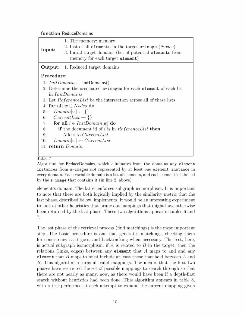
function ReduceDomains
Input:
1. The memory: memory2. List of all elements in the target s-image (Nodes)3. Initial target domains (list of potential elements from
memory for each target element)
Output: 1. Reduced target domains
Procedure:
1: InitDomain← InitDomains()2: Determine the associated s-images for each element of each list
in InitDomains3: Let ReferenceList be the intersection across all of these lists4: for all w ∈ Nodes do5: Domain[w]← {}6: CurrentList← {}7: for all i ∈ InitDomain[w] do8: if the document id of i is in ReferenceList then9: Add i to CurrentList
10: Domain[w]← CurrentList11: return Domain
Table 7Algorithm for ReduceDomains, which eliminates from the domains any elementinstances from s-images not represented by at least one element instance inevery domain. Each variable domain is a list of elements, and each element is labelledby the s-image that contains it (in line 2, above).
element’s domain. The latter enforces subgraph isomorphism. It is importantto note that these are both logically implied by the similarity metric that thelast phase, described below, implements. It would be an interesting experimentto look at other heuristics that prune out mappings that might have otherwisebeen returned by the last phase. These two algorithms appear in tables 6 and7.
The last phase of the retrieval process (find matchings) is the most importantstep. The basic procedure is one that generates matchings, checking themfor consistency as it goes, and backtracking when necessary. The test, here,is actual subgraph isomorphism: if A is related to B in the target, then therelations (links, edges) between any element that A maps to and and anyelement that B maps to must include at least those that held between A andB. This algorithm returns all valid mappings. The idea is that the first twophases have restricted the set of possible mappings to search through so thatthere are not nearly as many, now, as there would have been if a depth-firstsearch without heuristics had been done. This algorithm appears in table 8,with a test performed at each attempt to expand the current mapping given
15
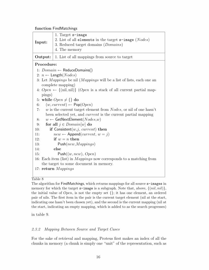
function FindMatchings
Input:
1. Target s-image2. List of all elements in the target s-image (Nodes)3. Reduced target domains (Domains)4. The memory
Output: 1. List of all mappings from source to target
Procedure:
1: Domain← ReduceDomains()2: n← Length(Nodes)3: Let Mappings be nil (Mappings will be a list of lists, each one an
complete mapping)4: Open ← {(nil, nil)} (Open is a stack of all current partial map-
pings)5: while Open 6= {} do6: (w, current)← Pop(Open)7: w is the current target element from Nodes, or nil of one hasn’t
been selected yet, and current is the current partial mapping8: w ← GetNextElement(Nodes,w)9: for all j ∈ Domain[w] do
10: if Consistent(w,j, current) then11: new ← Append(current, w = j)12: if w = n then13: Push(new,Mappings)14: else15: Push((w, new), Open)16: Each item (list) in Mappings now corresponds to a matching from
the target to some document in memory.17: return Mappings
Table 8The algorithm for FindMatchings, which returns mappings for all source s-images inmemory for which the target s-image is a subgraph. Note that, above, {(nil, nil)},the initial value of Open, is not the empty set {}; it has one element, an orderedpair of nils. The first item in the pair is the current target element (nil at the start,indicating one hasn’t been chosen yet), and the second is the current mapping (nil atthe start, indicating an empty mapping, which is added to as the search progresses)
in table 9.
2.3.2 Mapping Between Source and Target Cases
For the sake of retrieval and mapping, Proteus first makes an index of all thechunks in memory (a chunk is simply one “unit” of the representation, such as
16
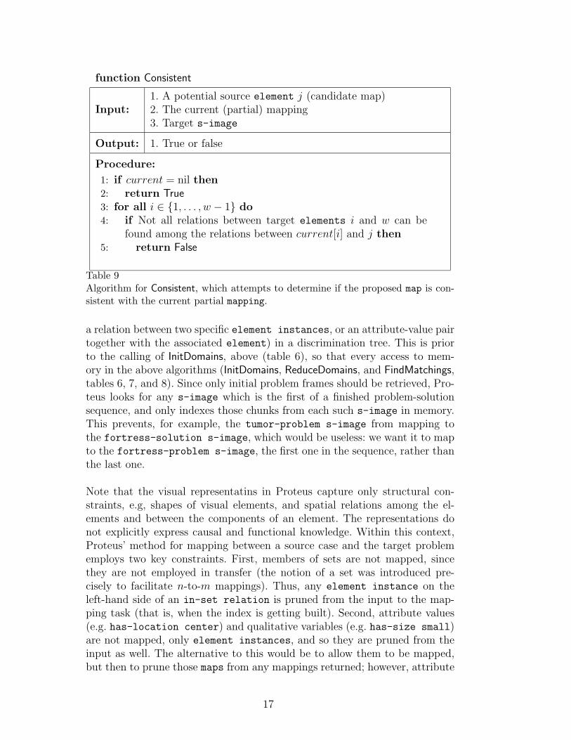
function Consistent
Input:1. A potential source element j (candidate map)2. The current (partial) mapping3. Target s-image
Output: 1. True or false
Procedure:
1: if current = nil then2: return True3: for all i ∈ {1, . . . , w − 1} do4: if Not all relations between target elements i and w can be
found among the relations between current[i] and j then5: return False
Table 9Algorithm for Consistent, which attempts to determine if the proposed map is con-sistent with the current partial mapping.
a relation between two specific element instances, or an attribute-value pairtogether with the associated element) in a discrimination tree. This is priorto the calling of InitDomains, above (table 6), so that every access to mem-ory in the above algorithms (InitDomains, ReduceDomains, and FindMatchings,tables 6, 7, and 8). Since only initial problem frames should be retrieved, Pro-teus looks for any s-image which is the first of a finished problem-solutionsequence, and only indexes those chunks from each such s-image in memory.This prevents, for example, the tumor-problem s-image from mapping tothe fortress-solution s-image, which would be useless: we want it to mapto the fortress-problem s-image, the first one in the sequence, rather thanthe last one.
Note that the visual representatins in Proteus capture only structural con-straints, e.g, shapes of visual elements, and spatial relations among the el-ements and between the components of an element. The representations donot explicitly express causal and functional knowledge. Within this context,Proteus’ method for mapping between a source case and the target problememploys two key constraints. First, members of sets are not mapped, sincethey are not employed in transfer (the notion of a set was introduced pre-cisely to facilitate n-to-m mappings). Thus, any element instance on theleft-hand side of an in-set relation is pruned from the input to the map-ping task (that is, when the index is getting built). Second, attribute values(e.g. has-location center) and qualitative variables (e.g. has-size small)are not mapped, only element instances, and so they are pruned from theinput as well. The alternative to this would be to allow them to be mapped,but then to prune those maps from any mappings returned; however, attribute
17
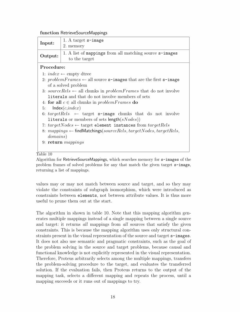
function RetrieveSourceMappings
Input:1. A target s-image2. memory
Output:1. A list of mappings from all matching source s-images
to the target
Procedure:
1: index← empty dtree2: problemFrames← all source s-images that are the first s-image
of a solved problem3: sourceRels ← all chunks in problemFrames that do not involve
literals and that do not involve members of sets4: for all c ∈ all chunks in problemFrames do5: Index(c,index)6: targetRels ← target s-image chunks that do not involve
literals or members of sets length(sNodes))7: targetNodes← target element instances from targetRels8: mappings← findMatchings(sourceRels, targetNodes, targetRels,
domains)9: return mappings
Table 10Algorithm for RetrieveSourceMappings, which searches memory for s-images of theproblem frames of solved problems for any that match the given target s-image,returning a list of mappings.
values may or may not match between source and target, and so they mayviolate the constraints of subgraph isomorphism, which were introduced asconstraints between elements, not between attribute values. It is thus moreuseful to prune them out at the start.
The algorithm in shown in table 10. Note that this mapping algorithm gen-erates multiple mappings instead of a single mapping between a single sourceand target: it returns all mappings from all sources that satisfy the givenconstraints. This is because the mapping algorithm uses only structural con-straints present in the visual representation of the source and target s-images.It does not also use semantic and pragmatic constraints, such as the goal ofthe problem solving in the source and target problems, because causal andfunctional knowledge is not explicitly represented in the visual representation.Therefore, Proteus arbitrarily selects among the multiple mappings, transfersthe problem-solving procedure to the target, and evaluates the transferredsolution. If the evaluation fails, then Proteus returns to the output of themapping task, selects a different mapping and repeats the process, until amapping succeeds or it runs out of mappings to try.
18
In the fortress/tumor problem, the “correct” mapping maps the set of roadsto the set of body parts, the fortress to the tumor, and the army to theray. When Proteus addresses this problem, the heuristics mentioned aboveprune out the sets of roads and body parts, as well as the shapes and sizesand positions of all the element instances. Thus, the only factors left toinfluence the mappings were the the element-instances themselves. Theelement-instances are Fortress, Tumor, Soldier-Path, Ray, Set1 (the setof roads around the fortress), and Set2 (the set of body parts surrounding thetumor). Proteus produced only one mapping:
(Fortress maps-to Tumor)
(Soldier-Path maps-to Ray)
(Set1 maps-to Set2)
In this case, the relationship between the soldier-path and the fortress (namely,that the soldier-path terminates at the fortress) mapped onto the analogousrelationship between the ray and the tumor (that the ray terminates at thetumor). This determined the mapping exactly, and no other mappings wereeven possible under this constraint.
On the other hand, for some of the other examples, a dozen or more mappingswere returned. In particular, we discovered an interesting conflict between theneeds of retrieval and mapping, and the needs of transfer: for transfer, if onlysome of the source elements map onto only some of the target elements, trans-fer can still be possible if the knowledge being transferred does not conflictwith anything else in the target. However, for retrieval and mapping, it isstraightforward to find all sources in memory for which the given target isa subgraph (viewing the target representation as a graph), but it is not asstraightforward to find all sources for which some part of the target may mapto some part of the source. Some of the examples involved mapping of thesource onto a target which involved other elements in other relationships, andso no mapping could be found using these methods, and the retrieval failed.
2.4 Transfer of the Problem-Solving Procedure
The transfer task takes as input a target problem, represented as a singles-image, an source case from memory, represented as a series of s-images
connected with transformations, and sets of possible mappings between thetarget and the first s-image of the retrieved source. Proteus transfers solu-tions from a source to the target and the evaluation step checks the quality ofthe transferred solutions. Transfer stops when a satisfactory solution is found.
Proteus adapts and transfers each transformation in the source problem tothe target. The transformations are transferred literally and the arguments
19
of those transformations can be adapted. For example, the transformationdecompose is used to turn a primitive element instance into some arbitrarynumber of resultants, taken as an argument. An argument of a transformation
can be an instance of one of three cases. Firstly, the argument can be a lit-eral, like the number four or the location bottom. Literals are transferredunchanged to the target.
Secondly, the argument could be a element instance member of the sources-image. In this case, the transfer procedure operates on the analogous elementin the target s-image. For example, in the first transformation in the fortressstory, the decomposed source soldier path gets adapted to the ray in thetarget tumor problem. Thirdly, the argument can be a function.
2.4.1 Transfer Method
We first describe Proteus’s transfer method informally, with reference to Fig-ure 4.
(1) Identify the first s-images of the target and source cases. Theseare the current source and target s-images.
(2) Identify the transformations and their associated arguments inthe current s-image of the source case. This step finds out how thesource case gets from its current s-image to the next s-image. In thefortress/tumor example, the transformation is decompose, with four asthe number-of-resultants argument (not shown).
(3) Identify the objects of the transformations. The object of the trans-formation is what object, if any, the transformation acts upon. For thedecompose transformation, the object is the soldier-path1 (the thickarrow in the top left s-image in Figure 4.)
(4) Identify the corresponding objects in the target problem. Ray1(the thick arrow in the bottom left s-image) is the corresponding com-ponent of the source case’s soldier-path1, as specified by the mapping
between the current source and target s-images (not shown). A singleobject can be mapped to any number of other objects 3 . If the object inquestion is mapped to more than one other object in the target, then thesame transformation is applied to all of them in the next step.
(5) Apply the transformation with the arguments to the targetproblem component. A new s-image is generated for the target prob-lem (bottom middle) to record the effects of the transformation. Thedecompose transformation is applied to the ray1, with the argumentfour. The result can be seen in the bottom middle s-image in Figure 4.The new rays are created for this s-image. Adaptation of the arguments
3 Though Proteus’s mapping generator will not do this, it is possible for mappingsassociated with transform-connections.
20
can happen in three ways, as described above: If the argument is an ele-ment of the source s-image, then its analog is found. If the argument is afunction, then the function is run (note that the function itself mayhave arguments which follow the same adaptation rules as transformationarguments). Otherwise the arguments are transferred literally.
(6) Map the original objects in the target to the new objects in thetarget. A transform-connection and mapping are created betweenthe target problem s-image and the new s-image (not shown). Maps
are created between the corresponding objects. In this example it wouldmean a map between ray1 in the left bottom s-image and the four raysin the second bottom s-image. A map is also created between the ray1 tothe set of thinner rays. A mapping from the correspondences of the firsts-image enables Proteus to automatically generate updated mappings
for the subsequent s-images.(7) Map the new objects of the target case to the corresponding ob-
jects in the source case. Here the rays of the second target s-image aremapped to soldier paths in the second source s-image. This step is nec-essary for the later iterations (i.e. going on to another transformation
and s-image). Otherwise the reasoner would have no way of knowingon which parts of the target s-image the later transformations wouldoperate.
(8) Check to see if there are any more source s-images. If there arenot, exit, and the solution is transferred. If there are further s-images inthe source case, set the current s-image equal to the next s-image andgo to step 1.
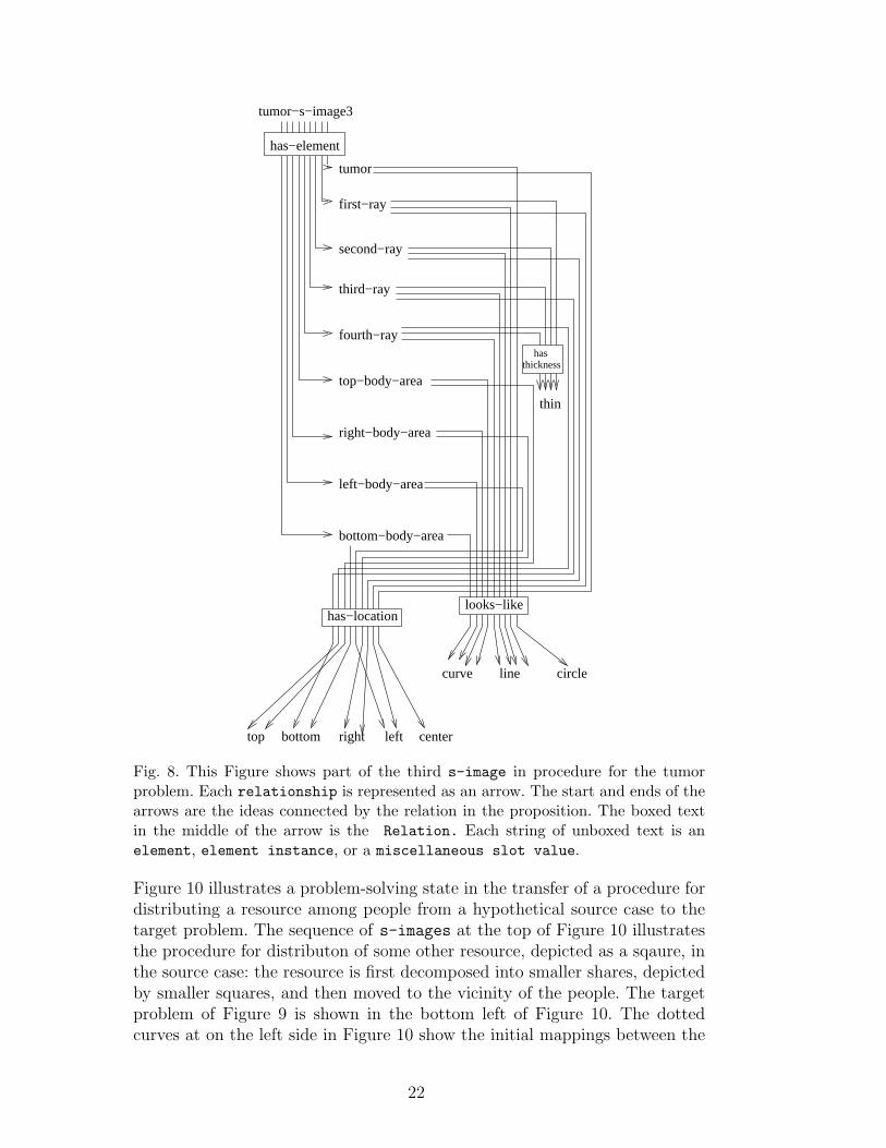
Figure 8 shows the third s-image in the squence generated for the tumorproblem by the above method.
2.4.2 Dynamic Generation of Intermediate Mappings
Step 7 in Proteus’ transfer method described in the previous subsection gen-erates a new mapping between the newly generated intermediate knowledgestate in the target problem and the corresponding intermediate state in thesource case. This is because the decomposet transformation preceding thisstate may create new visual elements in the state. Since this need for dynamicgeneration of mappings is a new finding of our work, in this subsection wediscuss it in some detail.
Consider a hypothetical problem in which two people need the same resource,but only one has access to it. This might be represented visually as illustratedin Figure 9, where the two circles represent people and the triangle representsthe one resource. The triangle’s proximity to one of the circles might representwhich person has possession of the resource.
21
tumor−s−image3
tumor
fourth−ray
top−body−area
right−body−area
first−ray
second−ray
third−ray
left−body−area
bottom−body−area
line circle
centerleftrightbottomtop
thin
curve
has
looks−like
thickness
has−element
has−location
Fig. 8. This Figure shows part of the third s-image in procedure for the tumorproblem. Each relationship is represented as an arrow. The start and ends of thearrows are the ideas connected by the relation in the proposition. The boxed textin the middle of the arrow is the Relation. Each string of unboxed text is anelement, element instance, or a miscellaneous slot value.
Figure 10 illustrates a problem-solving state in the transfer of a procedure fordistributing a resource among people from a hypothetical source case to thetarget problem. The sequence of s-images at the top of Figure 10 illustratesthe procedure for distributon of some other resource, depicted as a sqaure, inthe source case: the resource is first decomposed into smaller shares, depictedby smaller squares, and then moved to the vicinity of the people. The targetproblem of Figure 9 is shown in the bottom left of Figure 10. The dottedcurves at on the left side in Figure 10 show the initial mappings between the
22
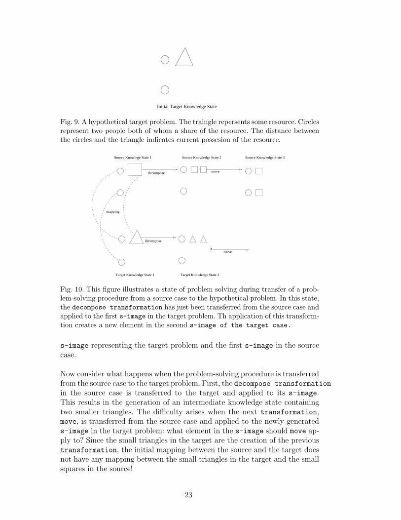
Initial Target Knowledge State
Fig. 9. A hypothetical target problem. The traingle repersents some resource. Circlesrepresent two people both of whom a share of the resource. The distance betweenthe circles and the triangle indicates current possesion of the resource.
decompose move
move?
decompose
mapping
Source Knowlege State 1
Target Knowledge State 1
Source Knowledge State 2 Source Knowledge State 3
Target Knowledge State 2
Fig. 10. This figure illustrates a state of problem solving during transfer of a prob-lem-solving procedure from a source case to the hypothetical problem. In this state,the decompose transformation has just been transferred from the source case andapplied to the first s-image in the target problem. Th application of this transform-tion creates a new element in the second s-image of the target case.
s-image representing the target problem and the first s-image in the sourcecase.
Now consider what happens when the problem-solving procedure is transferredfrom the source case to the target problem. First, the decompose transformation
in the source case is transferred to the target and applied to its s-image.This results in the generation of an intermediate knowledge state containingtwo smaller triangles. The difficulty arises when the next transformation,move, is transferred from the source case and applied to the newly generateds-image in the target problem: what element in the s-image should move ap-ply to? Since the small triangles in the target are the creation of the previoustransformation, the initial mapping between the source and the target doesnot have any mapping between the small triangles in the target and the smallsquares in the source!
23
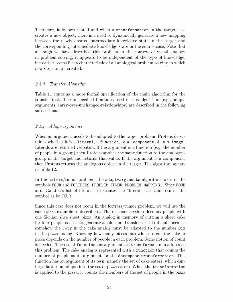
Therefore, it follows that if and when a transformation in the target casecreates a new object, there is a need to dynamically generate a new mappingbetween the newly created intermediate knowledge state in the target andthe corresponding intermediate knowledge state in the source case. Note thatalthough we have described this problem in the context of visual analogyin problem solving, it appears to be independent of the type of knowledge;instead, it seems like a characteristic of all analogical problem solving in whichnew objects are created.
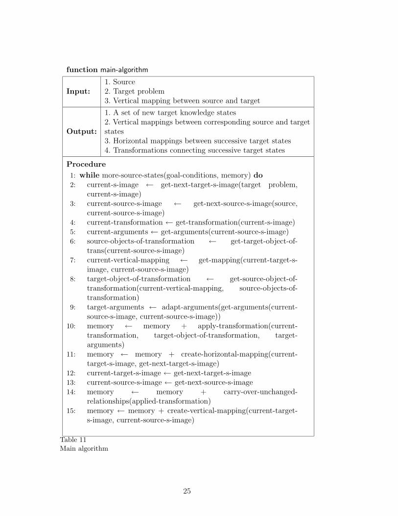
2.4.3 Transfer Algorithm
Table 11 contains a more formal specification of the main algorithm for thetransfer task. The unspecified functions used in this algorithm (e.g., adapt-arguments, carry-over-unchanged-relationships) are described in the followingsubsections.
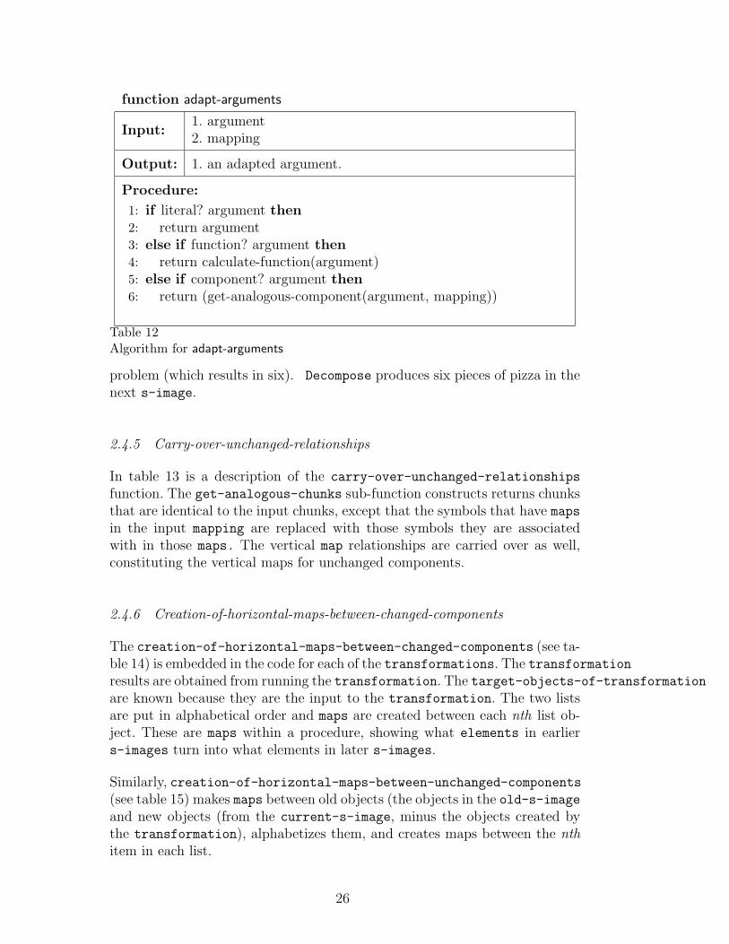
2.4.4 Adapt-arguments
When an argument needs to be adapted to the target problem, Proteus deter-mines whether it is a literal, a function, or a component of an s-image.
Literals are returned verbatim. If the argument is a function (e.g. the numberof people in a group) then Proteus applies the same function to the analogousgroup in the target and returns that value. If the argument is a component,then Proteus returns the analogous object in the target. The algorithm apearsin table 12.
In the fortress/tumor problem, the adapt-arguments algorithm takes in thesymbols FOUR and FORTRESS-PROBLEM-TUMOR-PROBLEM-MAPPING1. Since FOURis in Galatea’s list of literals, it executes the “literal” case and returns thesymbol as is: FOUR.
Since this case does not occur in the fortress/tumor problem, we will use thecake/pizza example to describe it. The reasoner needs to feed six people withone Sicilian slice sheet pizza. An analog in memory of cutting a sheet cakefor four people is used to generate a solution. Transfer is still difficult becausesomehow the Four in the cake analog must be adapted to the number Six
in the pizza analog. Knowing how many pieces into which to cut the cake orpizza depends on the number of people in each problem. Some notion of countis needed. The use of functions as arguments to transformations addressesthis problem. The cake analog is represented with a function that counts thenumber of people as its argument for the decompose transformation. Thisfunction has an argument of its own, namely the set of cake eaters, which dur-ing adaptation adapts into the set of pizza eaters. When the transformationis applied to the pizza, it counts the members of the set of people in the pizza
24
function main-algorithm
Input:1. Source2. Target problem3. Vertical mapping between source and target
Output:
1. A set of new target knowledge states2. Vertical mappings between corresponding source and targetstates3. Horizontal mappings between successive target states4. Transformations connecting successive target states
Procedure
1: while more-source-states(goal-conditions, memory) do2: current-s-image ← get-next-target-s-image(target problem,
current-s-image)3: current-source-s-image ← get-next-source-s-image(source,
current-source-s-image)4: current-transformation ← get-transformation(current-s-image)5: current-arguments ← get-arguments(current-source-s-image)6: source-objects-of-transformation ← get-target-object-of-
trans(current-source-s-image)7: current-vertical-mapping ← get-mapping(current-target-s-
image, current-source-s-image)8: target-object-of-transformation ← get-source-object-of-
transformation(current-vertical-mapping, source-objects-of-transformation)
9: target-arguments ← adapt-arguments(get-arguments(current-source-s-image, current-source-s-image))
10: memory ← memory + apply-transformation(current-transformation, target-object-of-transformation, target-arguments)
11: memory ← memory + create-horizontal-mapping(current-target-s-image, get-next-target-s-image)
12: current-target-s-image ← get-next-target-s-image13: current-source-s-image ← get-next-source-s-image14: memory ← memory + carry-over-unchanged-
relationships(applied-transformation)15: memory ← memory + create-vertical-mapping(current-target-
s-image, current-source-s-image)
Table 11Main algorithm
25
function adapt-arguments
Input:1. argument2. mapping
Output: 1. an adapted argument.
Procedure:
1: if literal? argument then2: return argument3: else if function? argument then4: return calculate-function(argument)5: else if component? argument then6: return (get-analogous-component(argument, mapping))
Table 12Algorithm for adapt-arguments
problem (which results in six). Decompose produces six pieces of pizza in thenext s-image.
2.4.5 Carry-over-unchanged-relationships
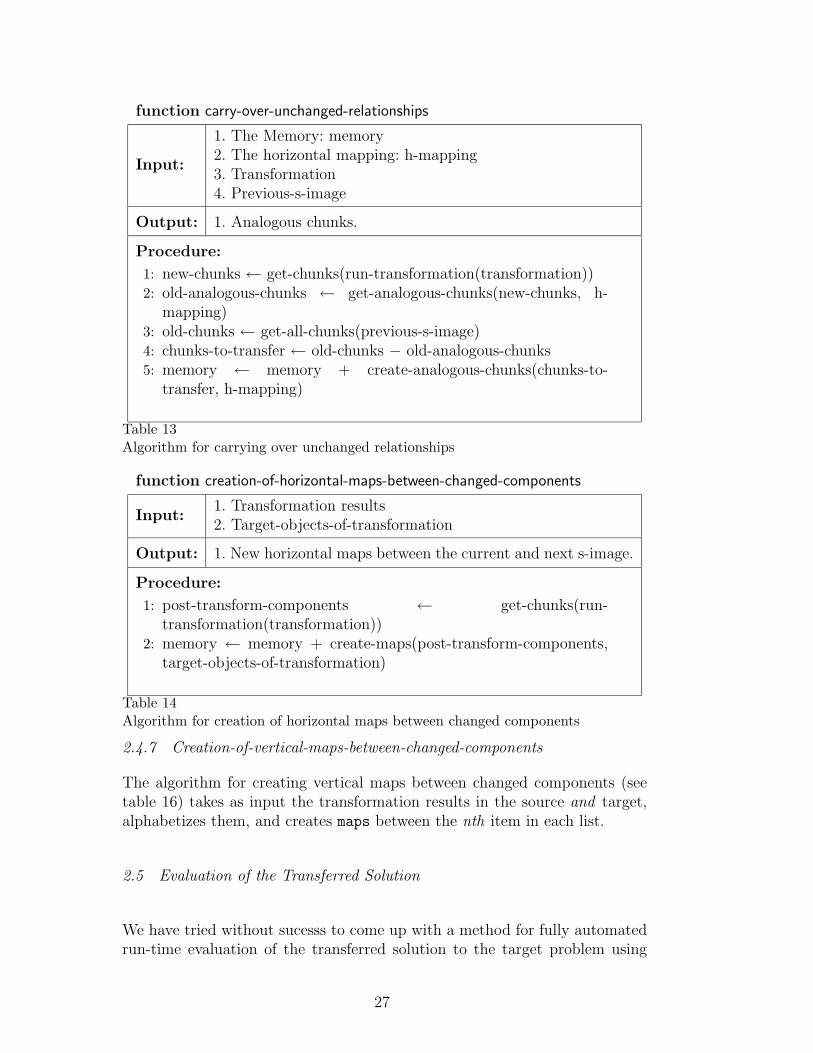
In table 13 is a description of the carry-over-unchanged-relationships
function. The get-analogous-chunks sub-function constructs returns chunksthat are identical to the input chunks, except that the symbols that have mapsin the input mapping are replaced with those symbols they are associatedwith in those maps. The vertical map relationships are carried over as well,constituting the vertical maps for unchanged components.
2.4.6 Creation-of-horizontal-maps-between-changed-components
The creation-of-horizontal-maps-between-changed-components (see ta-ble 14) is embedded in the code for each of the transformations. The transformationresults are obtained from running the transformation. The target-objects-of-transformationare known because they are the input to the transformation. The two listsare put in alphabetical order and maps are created between each nth list ob-ject. These are maps within a procedure, showing what elements in earliers-images turn into what elements in later s-images.
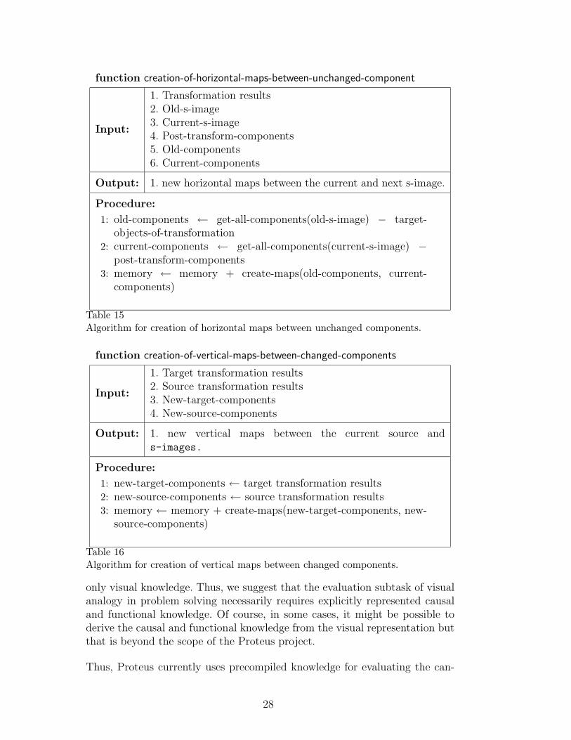
Similarly, creation-of-horizontal-maps-between-unchanged-components(see table 15) makes maps between old objects (the objects in the old-s-imageand new objects (from the current-s-image, minus the objects created bythe transformation), alphabetizes them, and creates maps between the nthitem in each list.
26
function carry-over-unchanged-relationships
Input:
1. The Memory: memory2. The horizontal mapping: h-mapping3. Transformation4. Previous-s-image
Output: 1. Analogous chunks.
Procedure:
1: new-chunks ← get-chunks(run-transformation(transformation))2: old-analogous-chunks ← get-analogous-chunks(new-chunks, h-
mapping)3: old-chunks ← get-all-chunks(previous-s-image)4: chunks-to-transfer ← old-chunks − old-analogous-chunks5: memory ← memory + create-analogous-chunks(chunks-to-
transfer, h-mapping)
Table 13Algorithm for carrying over unchanged relationships
function creation-of-horizontal-maps-between-changed-components
Input:1. Transformation results2. Target-objects-of-transformation
Output: 1. New horizontal maps between the current and next s-image.
Procedure:
1: post-transform-components ← get-chunks(run-transformation(transformation))
2: memory ← memory + create-maps(post-transform-components,target-objects-of-transformation)
Table 14Algorithm for creation of horizontal maps between changed components
2.4.7 Creation-of-vertical-maps-between-changed-components
The algorithm for creating vertical maps between changed components (seetable 16) takes as input the transformation results in the source and target,alphabetizes them, and creates maps between the nth item in each list.
2.5 Evaluation of the Transferred Solution
We have tried without sucesss to come up with a method for fully automatedrun-time evaluation of the transferred solution to the target problem using
27
function creation-of-horizontal-maps-between-unchanged-component
Input:
1. Transformation results2. Old-s-image3. Current-s-image4. Post-transform-components5. Old-components6. Current-components
Output: 1. new horizontal maps between the current and next s-image.
Procedure:
1: old-components ← get-all-components(old-s-image) − target-objects-of-transformation
2: current-components ← get-all-components(current-s-image) −post-transform-components
3: memory ← memory + create-maps(old-components, current-components)
Table 15Algorithm for creation of horizontal maps between unchanged components.
function creation-of-vertical-maps-between-changed-components
Input:
1. Target transformation results2. Source transformation results3. New-target-components4. New-source-components
Output: 1. new vertical maps between the current source ands-images.
Procedure:
1: new-target-components ← target transformation results2: new-source-components ← source transformation results3: memory ← memory + create-maps(new-target-components, new-
source-components)
Table 16Algorithm for creation of vertical maps between changed components.
only visual knowledge. Thus, we suggest that the evaluation subtask of visualanalogy in problem solving necessarily requires explicitly represented causaland functional knowledge. Of course, in some cases, it might be possible toderive the causal and functional knowledge from the visual representation butthat is beyond the scope of the Proteus project.
Thus, Proteus currently uses precompiled knowledge for evaluating the can-
28
didate solution to the target problem. As Proteus’ designers, we handcraftedthe propositions that a correct solution should have generated and compiledthem into the evaluation task. When Proteus proposes a candidate solution, itcompares the propositions generated by the candudate with the propositionsgenerated by the correct solution. If the candidate solution fails, then Proteusreturns to the output of retrieval task, and selects a different source case (ifone is available) and attempts to transfer its procedure to the target problem.
3 Evaluation of Proteus
Proteus is an integration of two systems: Geminus [43] and Galatea [5,7,6].The Geminus subsystem of Proteus is responsible for the retrieval, mappingand storage tasks, the Galatea subsystem is responsible for the transfer andevaluation tasks, including dynamic generation of mappings between the inter-mediate knowlede states in the source and target cases. Some of the evaluationof Proteus has been in the context of the Geminus and Galatea subsystems.
Uniformity: Proteus uses an uniform knowledge representation language,Covlan, for all tasks and subtasks of visual analogy in problem solving.
Generality: We have validated different parts of Proteus for a large rangeof problems. In particular, we have validated Geminus’ retrieval method fora variety of 2-D, vector graphic, line drawings. Similarly, we have validatedGalatea’s transfer method for problems ranging in complexity from cuttinga simple circular shape (e.g., a pizza) in analogy to cutting a similar shape(e.g., a cake) into smaller parts, to analogy-based design of a weed-trimmer,to a historical case study of James Clerk Maxwell’s reasoning about vorticesin electromagnetic fields [7]. We have validated Proteus itself for both thepizza-cake problem and the fortress-tumor peoblem.
The choice of the fortress/tumor problem as a running example in this paperhas been deliberate: The fortress/tumor problem is often considered to be acannonical example in the literature on analogy (e.g., [21]) and because earliercomputational models of the fortress/tumor classical example have relied onthe use of (non-visual) causal and functional knowledge [30]. Thus, success-ful execution of Proteus on the fortress/tumor problem partly confirms ourinitial hypothesis: visual knowledge alone is sufficient for analogical transferof problem-solving procedures in some task domains. It also leads to a re-finement of the initial hypothesis: while visual knowledge is sufficient for theretrieval, mapping, transfer and storage subtasks of analogy, the evaluationsubtask appears to require (non-visual) causal and functional knowledge.
29
Efficiency: We have conducted efficiency experiments with Geminus. In ourexperiments, the long-term memory contained 42 source cases; the number ofvisual elements in the indexical s-images of the source cases ranged from 3to over 50, with an average about 12’ and the number of propositions in se-mantic network representing the s-images ranged from a couple of dozen toover eight thousand. The experiments were conducted with 21 target prob-lems; each of the s-images in the targer problems contains 2 to 5 visualelements and up to several dozen propositions. Running on a desktop work-statation, Geminus retrieved the relevant s-images in about 9.32 seconds onaverage across all 21 target s-images), doing an average of about 1.49 millionmemory accesses (to the index of propositions across all the source s-images)per retrieval. Even in the worst-case (characterized by the size of the tar-get s-image, Geminus took under a minute to retrieve the relevant sources-images.
Recall that following MAC/FAC [17] the Geminus decomposes the retrievaltask into two subtasks: reminding and selection. Recall also that followingACME [31], Geminus uses a constraint-satisfaction method for the selectiontask. Ablation experiments with Gemimus [43], in which we removed the re-minding subtask of the retrieval task and performed retrieval based solely oncontraint satisfaction, revealed no significant degradation in its performance.This leads us to the following conjecture about case retrieval in general: whenconstraint-satisfaction is used for selection, there may be little need for re-minding using feature vectors. This conjecture needs further examination.
Cognitive Modeling: We have used Galatea to model the input-outputbehavior of human subjects engaged in analogy-based design [6]. In theseexperiments [3], human subjects were given a source case of a design of theentrance to a clean-air laboratory, where the problem was articulated in textand the solution was expressed both in text and in a drawing. The source casealso contained a problem-solving procedure articulated in text form, whichconverted an entrance with a single door to a vestibule with double doors. Inthe target problem, which was expressed in text form, the subjects were askedto draw the design a portable weed-trimmer in analogy to the entrance to theclean-air laboratory. We then used Galatea to solve exactly the same targetproblem with exactly the same source case, except that in Galatea both thesource case and the target problem were expressed only visually. We foundthat Galatea successfully solved the above problem.
For four of the human subjects in the above study, we conducted an addi-tional experiment with Galatea. We ran Galatea under different initial knowl-edge conditions, but without any change to its computational process, itsknowledge representation language, or its algorithms. We found that by sim-ply changing the intial knowledge conditions, we could make Galatea replicate
30
ACMEIAM
LISA
Larkin & SimonNarayanan et al.
NIALWHISPERGeoRepFROB
REBUILDERFABELDIVAJUXTAMAGIPANANALOGYLetterSpirit
I−SME
AnalogicalReasoning
Visual Reasoning
Proteus
Winston
Problem Sovling
PICHEFProdigy
ToRQUE
SME
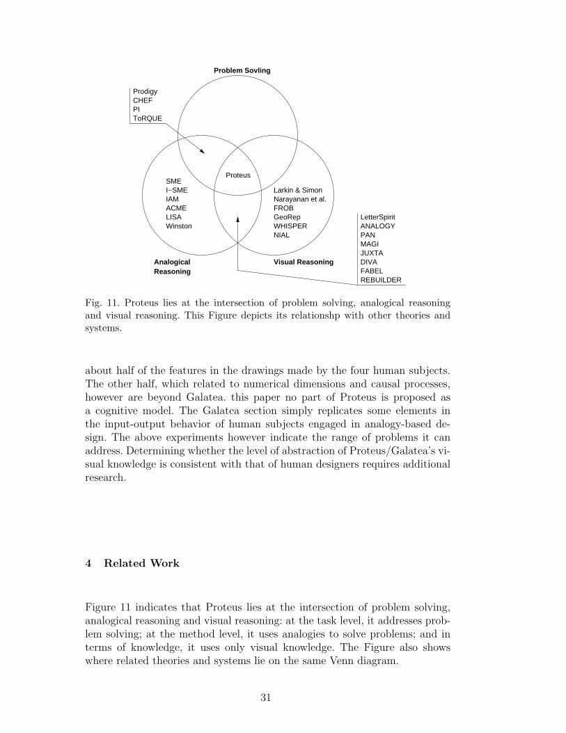
Fig. 11. Proteus lies at the intersection of problem solving, analogical reasoningand visual reasoning. This Figure depicts its relationshp with other theories andsystems.
about half of the features in the drawings made by the four human subjects.The other half, which related to numerical dimensions and causal processes,however are beyond Galatea. this paper no part of Proteus is proposed asa cognitive model. The Galatea section simply replicates some elements inthe input-output behavior of human subjects engaged in analogy-based de-sign. The above experiments however indicate the range of problems it canaddress. Determining whether the level of abstraction of Proteus/Galatea’s vi-sual knowledge is consistent with that of human designers requires additionalresearch.
4 Related Work
Figure 11 indicates that Proteus lies at the intersection of problem solving,analogical reasoning and visual reasoning: at the task level, it addresses prob-lem solving; at the method level, it uses analogies to solve problems; and interms of knowledge, it uses only visual knowledge. The Figure also showswhere related theories and systems lie on the same Venn diagram.
31
4.1 Analogical Reasoning
As we mentioned earlier, Proteus’ decomposition of the retrieval task intofeature-based reminding and structure-based selection follows MAC/FAC [17].However, while MAC/FAC uses structure-mapping for the selection task, Pro-teus uses constraint satisfaction with backtracking. As we noted earlier, theexperiments with the Geminus subsystem of Proteus indicate that the two-stage decomposition of the retrieval task provides little computational benefitover just one-stage retrieval based on constraint satisfaction [43] .
The Structure-Mapping Engine [10] is based on cognitive model of Structure-Mapping [20]. It constrains the mapping problem with several rules includingthe systematicity principle, which holds that higher-order (more nested) rela-tional similarities are preferred over lower-order (less nested) similarities. SMEfinds many possible mappings between a source and a target, then evaluatesthem according to the map rules. SME however neither provides a content ac-count of visual analogies, nor does it address problem solving, i.e., it transfersrelations, not procedures.
I-SME [16] and the Incremental Analogy Machine (IAM) [33] are incrementalmappers. An incremental mapper generates a mapping as objects in a givencase are introduced to the mapper one at a time. Proteus does incrementalmapping of a different kind and at a different stage of processing: if and whenan operation creates a new object during transfer of a problem-solving proce-dure it dynamically generates new mappings for the newly created objects.
As we mentioned earlier, Proteus’ view of retrieval as a constraint satisfactionproblem follows that of ACME [31]. ACME (for Analogical Constraint Map-ping Engine) uses structural, semantic, and pragmatic constraints for map-ping. Structure, in this sense, does not necessarily mean physical appearance,but the nature of the representation: elements are structurally similar if theyshare the same relational structure with other elements. Semantic similarityrefers to elements are either identical symbols or share predicates (e.g. a com-mon superordinate). Pragmatic constraints pertain to the relative importanceof some propositions in the representation given the goals of the agent. Themapping is generated as a result of a constraint-satisfaction spreading activa-tion network. Transfer in ACME involves transferring relations and postulat-ing new elements from the source analog. ACME neither provides a contentaccount of visual analogy, nor does it address problem solving, i.e., it transfersfacts, not procedures.
LISA [32] is cognitive model of analogical mapping. Propositions are madeup of units spread activation to each other. Arguments of propositions fire insynchrony with the case roles to which they are bound, and out of synchrony
32
with other case roles and arguments. Through spreading activation, the bestmap is found.
Winston [42] describes an analogical mapper based on content account of itsdomain (understanding political stories). The content account is based oncausality and functionality. The mapper generate all possible mappings, andthen ranks them. While Proteus’ content and process accounts are very dif-ferent from that of Winston, like Winston’s work, Proteus too emphasizes theimportance of interaction between knowledge content and reasoning processes.
4.2 Analogical Problem Solving
CHEF [28] is a case-based reasoner that adapts cooking recipies from a sourceto a target. CHEF uses non-visual causal and functional knowledge. Further,it neither represents intermediate knowledge states, nor transfers proceduresthat create new objects.
The Derivational Analogy theory, [41,40,38] implemented in the Prodigy sys-tem, analogically transfers problem-solving procedures from source cases totarget problems. It uses traces of problem solving, called derivations, for en-abling the transfer. Derivations are scripts of the steps of problem solving,which contain justifications for why the specific steps in problem solving werechosen over others. Prodigy also allows for adaptation of the transferred pro-cedure. Like CHEF, Prodigy too uses non-visual causal and functional knowl-edge. Further, in Prodigy, the intermediate knowledge states are not explicitlyrepresented or saved in the case memory. Instead, a stored case contains onlythe record of the changes made to the states, which allows the knowledgestates to be inferred. In contrast, Proteus explicitly represents intermediateknowledge and stores them in the case memory. Furthemore, whenever anoperation in the transferred procedure creates new objects, Proteus dynam-ically generates new mapping between the intermediate knowledge states inthe target and the source case. Prodigy is able to avoid generation of theseintermediate mappings because the problems with which it deals do not haveprocedures that create new objects.
The Process of Induction (PI) model [30] is the only implemented compu-tational model, other than Proteus, that solves the fortress/tumor problem.However, unilke Proteus, it uses non-visual causal and functional knowledge.PI does not represent intermediate knowledge states or generate new map-pings between them. This is because it does not do analogical transfer in theusual sense of the term. Instead, it first uses a production system to solve thefortress problem. Once PI solves the tumor problem, it induces an abstractschema that works as a single rule that aapplies to both problems.
33
The ToRQUE2 system [25–27] uses a taxonomy of generic structural trans-formations that can be applied to physical systems . These transformationswere found to be useful in modeling protocols of human subjects solving aproblem dealing with spring systems. ToRQUE2’s structural representationsare different from Proteus’ visual representations: the structural representa-tions describe a system’s physical composition but typically include only theinformation directly relevant for predicting the causal behaviors of the system.Structural knowledge, like a schematic, shows the components of the systemand the connections among them but leaves out other visual information, suchas what a component wire looks like, which side of a pump is up, etc.
4.3 Visual Knowledge and Reasoning
Larkin and Simon [34] describe a system that reasons about physical systemssuch as pulley systems. In their representation, objects are not representedexplicitly, but implicitly through locations: when one location is attended to,all information there is attended to. To answer a question about a pulleysystem, the reasoner uses some non-visual causal knowledge of physics alongwith the visual knowledge.
The NIAL system [23] distinguishes between depictive and descriptive repre-sentations (corresponding to bitmape and propositional representations), aswell as a distinction between visual and spatial (corresponding to where some-thing is and what something is). The descriptive representation is stored inmemory, and the depictive is generated in a working memory when needed.
WHISPER [18] is a problem-solving system that can request observationsfrom and make changes to depictive diagrams of a blocks world. It knowsabout stability and falling objects. It can visualize something rotating in thediagram and determine when it will hit another object. The system’s goal isto move all blocks until they are stable. It moves them, then simulates howthey will act (in a bitmap “retina”) for evaluation. While WHISPER usesvisual knowledge for many of its tasks, it uses non-visual causal knowledge forevaluation by simulation.
The FROB system [15] uses Qualitative Spatial Reasoning (QSR) [14] to rea-son about physical systems, e.g., figuring out the paths of balls on a landscapeand whether will collide. In QSR, an agent needs both a metric diagram repre-sentation and a place vocabulary representation. A metric diagram shows thequantitative aspects of the system, like sizes of objects expressed in numbers.The place vocabulary is a qualitative representation of location and shapesof objects. A place is a region of space where some important property (e.g.being in contact with something) is constant.
34
GeoRep [13] takes in 2-D line drawings and outputs the visual relations in it.First it uses a LLRD (low-level relational describer) module to aggregate vi-sual primitives. Its visual primitives are: line segments, circular arcs, circles, el-lipses, splines, and text strings. It finds relations of the following kinds: group-ing, proximity detection, reference frame relations, parallel lines, connectionrelations, polygon and polyline detection, interval relations, and boundary de-scriptions. Then the HLRD (high-level relational describer) finds higher-level,more domain-specific primitives and relations. GeoRep’s content account is atthe low level – the higher level account is left up to the modeler. Althoughthough the reasoning goal in Proteus is very different from that of GeoRep,its knowledge representation language, Covlan, has considerable overlap withGeoRep’s vocabulary. Covlan, however, also provides a vocabulary for repre-senting visual operations, such as move-to-location, and for representing asequence of visual operations in a procedure.
Narayanan, Suwa and Motoda’s model [36] describe a cognitive model forpredicting the behavior of physical systems from their diagrams. The visualknowledge is represented with diagram frames (representing lines and spacesand connections between them) and occupancy array representations (repre-senting, for each pixel, what kind of object is located there). The vocabulary ofProteus’ knowledge representation language is at the same level of abstractionas Narayanan, Suwa and Motoda’s model.
4.4 Visual Analogy
We have already described the ANALOGY and Letter Spirit systems in theintroduction. A couple of addtional remarks about Letter Spirit are in or-der. Letter Spirit transfers single transformations/attributes (e.g. crossbar-suppressed) and therefore cannot make analogical transfer of procedures (e.g.moving something, then resizing it) which Proteus can do. In contrast, onecan see how Proteus might be applied to the Letter Spirit’s font domain: Thestylistic guidelines in LetterSpirit, such as “crossbar suppressed” are like thevisual transformations in Proteus: “crossbar supressed would be a transforma-tion of removing an element from an s-image, where element removed wouldthe crossbar and the s-image would be the prototype letter f. Once the trans-formation is expressed in Proteus’ vocabulary, it could be applied to all theother letters one by one. In this way, Proteus is more general than LetterSpirit.
Like ANALOGY, the PAN system [37] uses graph-like representations of ab-stract diagrams and outputs transformations that will turn one diagram intoanother. Neither ANALOGY nor PAN however can transfer problem-solvingprocedures.
35
MAGI [11] takes visual representations and uses the Structure-Mapping En-gine to find examples of symmetry and repetition in a single diagram. JUXTA[12] uses MAGI in its processing of a diagram of two parts. It outputs a map-ping between the images, and notes distracting and important differences.Both MAGI and JUXTA use GeoRep’s visual representation language.
DIVA [4] is another analogical mapper that uses visual representations. Specif-ically, it uses the Java Visual Object System. its examples is the fortress/tumorproblem, however, it does not transfer problem solving procedures.
In computer-aided design, FABEL [19] was an early project to explore theautomated reuse of diagrammatic cases. In particular, TOPO [2], a subsystemof FABEL, used the maximum common subgraph (MCS) of the target drawingwith the stored drawings for retrieve similar drawings.
REBUILDER [24] is a case-based reasoner that does analogical retrieval, map-ping, and transfer of software design class diagrams. The diagrams are repre-sented structurally, not visually, however. This means that while REBUILDERmay represent that a teacher has a relationship with a school for example, itdoes not represent as any left-of/right-of, above/below connection betweenthem.
5 Conclusion
We have described a computational theory of visual analogy in problem solvingthat addresses all major subtasks of visual analogy. Proteus is a computerprogram that implements and substantiates the theory. The contributions ofthis paper are that (a) for the first time it describes Proteus as a whole,and (b) it provides a detailed account of the knowledge representations andalgorithms used by Proteus. Proteus provides two main things: (a) a contentaccount and (b) a process account for visual analogy in problem solving. Ourwork on Proteus leads us to the following three conclusions:
I: Visual knowledge alone is sufficient for some subtasks of analogical problem-solving.
We started this work with the hypothesis that visual knowledge alone is suffi-cient for analogical problem solving. We deliberately chose the fortress/tumorproblem to test this hypothesis not only because it is a classic example of ana-logical problem solving but also because previous computational models forthis problem, such as PI [30], relied solely on non-visual causal and functionalknowledge. Based on Proteus, we now refine this hypothesis: visual knowledgealone is sufficient for the retrieval, mapping and transfer subtasks of analogical
36
transfer of problem-solving procedures.
Proteus also shows that while visual knowledge is useful for the mapping task,it alone is not suffiicent for generating a single mapping between a targetproblem and a retrieved source case matching the target. The difficulty isthat while visual knowledge captures structural constraints (e.g., shapes, andspatial relations), it does not capture causal and functional knowledge of eitherthe source or the target, which leaves the mapping task underconstrainedand results in the generation of multiple mappings between the target andthe source. Note that this finding is consistent with earlier work on visualanalogy: while ANALOGY does do mapping based on visual knowledge alone,it does so in a context entirely different from and much simpler than transferof problem-solving procedures, and, in Letter Spirit, the mapping is compiledinto the system’s knowledge.
In addition, Proteus shows that visual knowledge alone cannot enable evalua-tion of the transferred solution for the target problem. This finding is consis-tent with other work on visual reasoning work, such as WHISPER [18], whichuses non-visual causal knowledge for evaluation.
II: Visual analogy is enabled by knowledge of shapes, spatial relations, andshape and spatial transformations.
Proteus uses Covlan, an uniform knowledge representation language, for allsubtasks of visual knowledge. In particular, Proteus shows that the retrievaltask of visual analogy is enabled by symbolically represented knowledge ofshapes of objects (e.g., spline, ellipse) and spatial relations between the shapes(e.g., above, left-of) in drawings representing the target and source cases.It also shows that the transfer task requires additional knowledge, namely,symbolic knowledge of transformations of shapes and spatial relations fromone knowledge state to the next (e.g., move, move-set). The latter is requiredbecause of the need to represent the problem solving steps and their effects. Ofcourse, Covlan is incomplete; a larger class of domains may require additionsof its vocabulary.
III: Successful analogical transfer of strongly-ordered procedures in whichnew objects are created requires generation of new mappings between theintermediate knowledge states in the source and target cases.
An unexpected finding of our work on Proteus is that that the successful trans-fer of strongly-ordered procedures in which new objects are created requiresthe problem-solver to dynamically generate intermediate knowledge states andnew mappings between the intermediate knowledge states of the source andtarget analogs. This is because the newly created objects are acted on by lateroperations. In the tumor problem, for example, the strong ray is first turnedinto a several weaker rays. When the problem solver transfers the move solid-
37
ers operation from the fortress case and seeks to apply the move operation tothe tumor problem, how does it know that the objects corresponding to thesoliders are the weaker rays? It must have some mapping to make this infer-ence, and since the weaker rays do not exist in the start state of the tumorproblem, this mapping cannot be part of the initial mapping between the tar-get and the source. Therefore, the new knowledge state with the weaker raysmust be generated, and then a new mapping must be made between the newknowledge state and the corresponding knowledge state in the source case.
Acknowledgements
Nancy Nersessian has been a collaborator on the work on Galatea subsystemof the Proteus system.
References
[1] M. Anderson, B. Meyer, and P. Olivier, editors. Diagrammatic Representationand Reasoning. Springer, 2002.
[2] K. Borner, P. Eberhard, E.-C. Tammer, and C.-H. Coulon. Structural similarityand adaptation. In I. Smith and B. Faltings, editors, Advances in Cased-Based Reasoning: Proc. 3rd European Workshop on Cased-Based Reasoning,volume 1168 of Lecture Notes in Artificial Intelligence, pages 58–75, Lausanne,Switzerland, 1996. Springer-Verlag.
[3] D. L. Craig, R. Catrambone, and J. Nersessian, Nancy. Perceptual simulationin analogical problem solving. In Model-Based Reasoning: Science, Technology,& Values, pages 167–191. Kluwer Academic / Plenum Publishers, 2002.
[4] D. Croft and P. Thagard. Dynamic imagery: A computational model of motionand visual analogy. In L. Magnani and N. J. Nersessian, editors, Model-BasedReasoning: Science, Technology, & Values, pages 259–274. Kluwer Academic:Plenum Publishers, 2002.
[5] J. Davies and A. K. Goel. Visual analogy in problem solving. In Proceedings ofthe International Joint Conference for Artificial Intelligence 2001, pages 377–382. Morgan Kaufmann Publishers, 2001.
[6] J. Davies, A. K. Goel, and N. J. Nersessian. Transfer in visual case-basedproblem-solving. In Proceedings of the 6th International Conference on Case-Based Reasoning. Springer-Verlag, 2005.
[7] J. Davies, N. J. Nersessian, and A. K. Goel. Visual models in analogical problemsolving. Foundations of Science, 2002. special issue on Model-Based Reasoning:Visual, Analogical, Simulative.
38
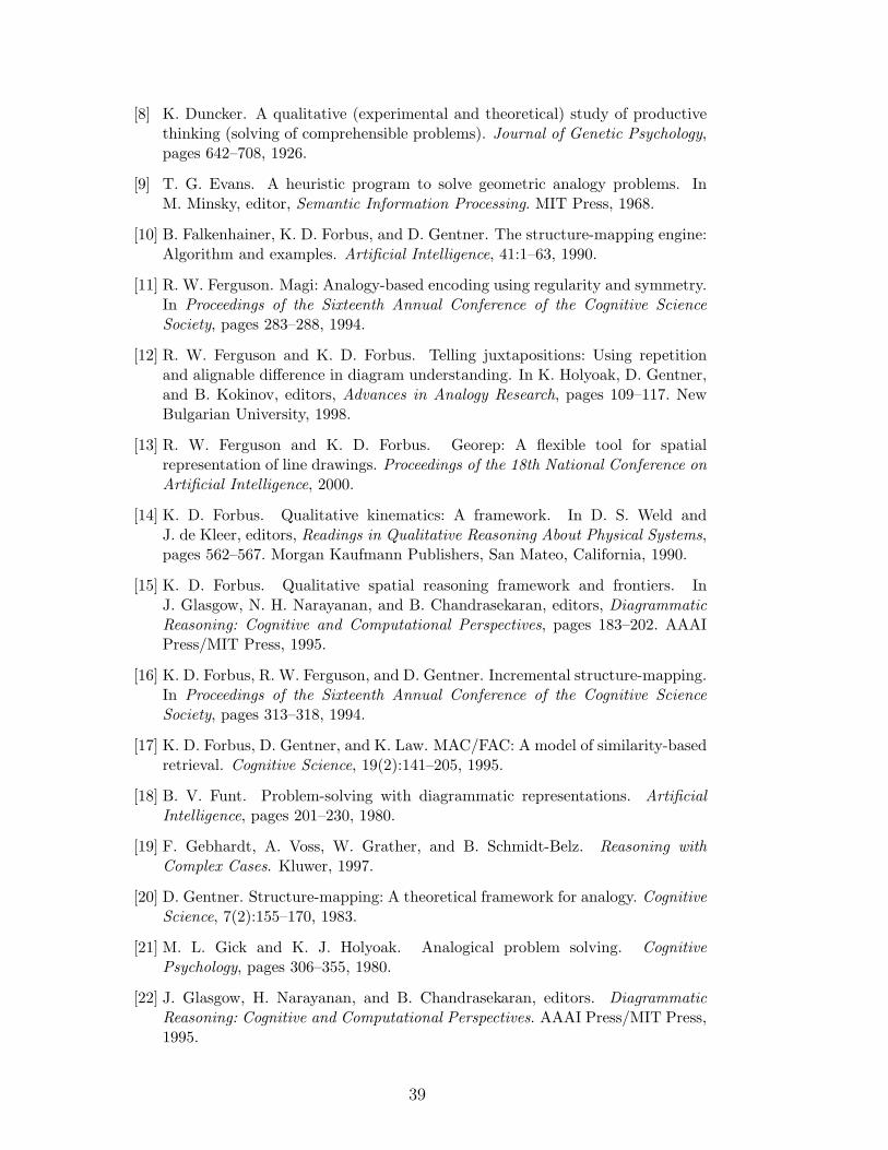
[8] K. Duncker. A qualitative (experimental and theoretical) study of productivethinking (solving of comprehensible problems). Journal of Genetic Psychology,pages 642–708, 1926.
[9] T. G. Evans. A heuristic program to solve geometric analogy problems. InM. Minsky, editor, Semantic Information Processing. MIT Press, 1968.
[10] B. Falkenhainer, K. D. Forbus, and D. Gentner. The structure-mapping engine:Algorithm and examples. Artificial Intelligence, 41:1–63, 1990.
[11] R. W. Ferguson. Magi: Analogy-based encoding using regularity and symmetry.In Proceedings of the Sixteenth Annual Conference of the Cognitive ScienceSociety, pages 283–288, 1994.
[12] R. W. Ferguson and K. D. Forbus. Telling juxtapositions: Using repetitionand alignable difference in diagram understanding. In K. Holyoak, D. Gentner,and B. Kokinov, editors, Advances in Analogy Research, pages 109–117. NewBulgarian University, 1998.
[13] R. W. Ferguson and K. D. Forbus. Georep: A flexible tool for spatialrepresentation of line drawings. Proceedings of the 18th National Conference onArtificial Intelligence, 2000.
[14] K. D. Forbus. Qualitative kinematics: A framework. In D. S. Weld andJ. de Kleer, editors, Readings in Qualitative Reasoning About Physical Systems,pages 562–567. Morgan Kaufmann Publishers, San Mateo, California, 1990.
[15] K. D. Forbus. Qualitative spatial reasoning framework and frontiers. InJ. Glasgow, N. H. Narayanan, and B. Chandrasekaran, editors, DiagrammaticReasoning: Cognitive and Computational Perspectives, pages 183–202. AAAIPress/MIT Press, 1995.
[16] K. D. Forbus, R. W. Ferguson, and D. Gentner. Incremental structure-mapping.In Proceedings of the Sixteenth Annual Conference of the Cognitive ScienceSociety, pages 313–318, 1994.
[17] K. D. Forbus, D. Gentner, and K. Law. MAC/FAC: A model of similarity-basedretrieval. Cognitive Science, 19(2):141–205, 1995.
[18] B. V. Funt. Problem-solving with diagrammatic representations. ArtificialIntelligence, pages 201–230, 1980.
[19] F. Gebhardt, A. Voss, W. Grather, and B. Schmidt-Belz. Reasoning withComplex Cases. Kluwer, 1997.
[20] D. Gentner. Structure-mapping: A theoretical framework for analogy. CognitiveScience, 7(2):155–170, 1983.
[21] M. L. Gick and K. J. Holyoak. Analogical problem solving. CognitivePsychology, pages 306–355, 1980.
[22] J. Glasgow, H. Narayanan, and B. Chandrasekaran, editors. DiagrammaticReasoning: Cognitive and Computational Perspectives. AAAI Press/MIT Press,1995.
39
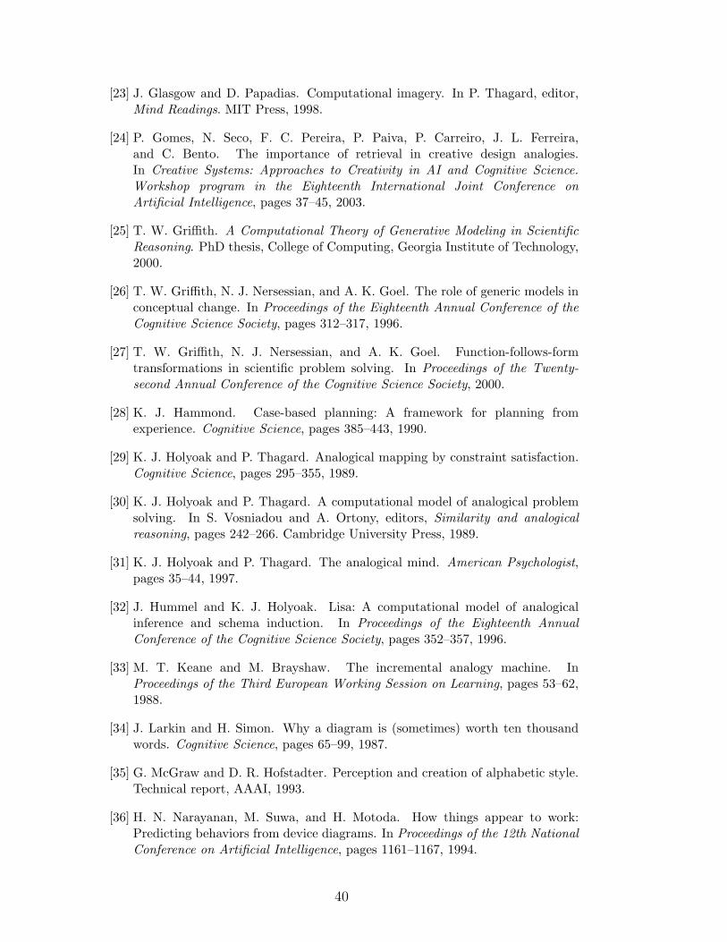
[23] J. Glasgow and D. Papadias. Computational imagery. In P. Thagard, editor,Mind Readings. MIT Press, 1998.
[24] P. Gomes, N. Seco, F. C. Pereira, P. Paiva, P. Carreiro, J. L. Ferreira,and C. Bento. The importance of retrieval in creative design analogies.In Creative Systems: Approaches to Creativity in AI and Cognitive Science.Workshop program in the Eighteenth International Joint Conference onArtificial Intelligence, pages 37–45, 2003.
[25] T. W. Griffith. A Computational Theory of Generative Modeling in ScientificReasoning. PhD thesis, College of Computing, Georgia Institute of Technology,2000.
[26] T. W. Griffith, N. J. Nersessian, and A. K. Goel. The role of generic models inconceptual change. In Proceedings of the Eighteenth Annual Conference of theCognitive Science Society, pages 312–317, 1996.
[27] T. W. Griffith, N. J. Nersessian, and A. K. Goel. Function-follows-formtransformations in scientific problem solving. In Proceedings of the Twenty-second Annual Conference of the Cognitive Science Society, 2000.
[28] K. J. Hammond. Case-based planning: A framework for planning fromexperience. Cognitive Science, pages 385–443, 1990.
[29] K. J. Holyoak and P. Thagard. Analogical mapping by constraint satisfaction.Cognitive Science, pages 295–355, 1989.
[30] K. J. Holyoak and P. Thagard. A computational model of analogical problemsolving. In S. Vosniadou and A. Ortony, editors, Similarity and analogicalreasoning, pages 242–266. Cambridge University Press, 1989.
[31] K. J. Holyoak and P. Thagard. The analogical mind. American Psychologist,pages 35–44, 1997.
[32] J. Hummel and K. J. Holyoak. Lisa: A computational model of analogicalinference and schema induction. In Proceedings of the Eighteenth AnnualConference of the Cognitive Science Society, pages 352–357, 1996.
[33] M. T. Keane and M. Brayshaw. The incremental analogy machine. InProceedings of the Third European Working Session on Learning, pages 53–62,1988.
[34] J. Larkin and H. Simon. Why a diagram is (sometimes) worth ten thousandwords. Cognitive Science, pages 65–99, 1987.
[35] G. McGraw and D. R. Hofstadter. Perception and creation of alphabetic style.Technical report, AAAI, 1993.
[36] H. N. Narayanan, M. Suwa, and H. Motoda. How things appear to work:Predicting behaviors from device diagrams. In Proceedings of the 12th NationalConference on Artificial Intelligence, pages 1161–1167, 1994.
40
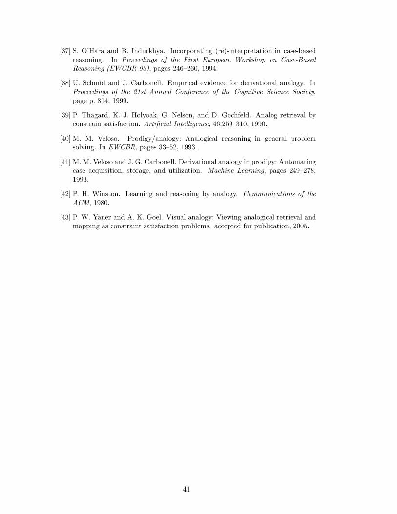
[37] S. O’Hara and B. Indurkhya. Incorporating (re)-interpretation in case-basedreasoning. In Proceedings of the First European Workshop on Case-BasedReasoning (EWCBR-93), pages 246–260, 1994.
[38] U. Schmid and J. Carbonell. Empirical evidence for derivational analogy. InProceedings of the 21st Annual Conference of the Cognitive Science Society,page p. 814, 1999.
[39] P. Thagard, K. J. Holyoak, G. Nelson, and D. Gochfeld. Analog retrieval byconstrain satisfaction. Artificial Intelligence, 46:259–310, 1990.
[40] M. M. Veloso. Prodigy/analogy: Analogical reasoning in general problemsolving. In EWCBR, pages 33–52, 1993.
[41] M. M. Veloso and J. G. Carbonell. Derivational analogy in prodigy: Automatingcase acquisition, storage, and utilization. Machine Learning, pages 249–278,1993.
[42] P. H. Winston. Learning and reasoning by analogy. Communications of theACM, 1980.
[43] P. W. Yaner and A. K. Goel. Visual analogy: Viewing analogical retrieval andmapping as constraint satisfaction problems. accepted for publication, 2005.
41