Embed Size (px)
Citation preview

Protective Relaying Considerations for Standby Generation Systems
Minnesota Power Systems ConferenceNovember 6, 2018Timothy J. Coyle, PE

Introduction• Historically standby generators were designed for isolated
operation • Critical systems now demand closed-transition transfer• Utilities offer incentives for transfer of load or continuous
parallel operation to control demand• Now seeing large installations (up to 10 MW) based on small
(1.5-3 MW) units operated in parallel with each other and utility• Multi-function µP-based relays provide enhanced capability at
low cost, however:• Complexity of protection may compromise reliability
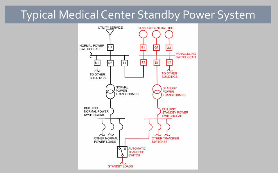
Typical Medical Center Standby Power System
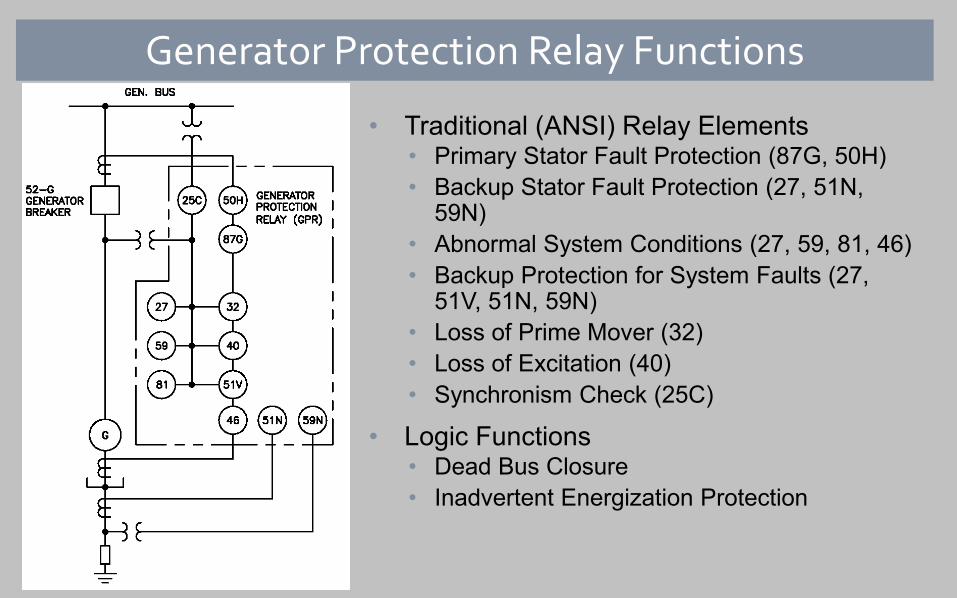
Generator Protection Relay Functions
• Traditional (ANSI) Relay Elements• Primary Stator Fault Protection (87G, 50H)• Backup Stator Fault Protection (27, 51N,
59N)• Abnormal System Conditions (27, 59, 81, 46)• Backup Protection for System Faults (27,
51V, 51N, 59N)• Loss of Prime Mover (32)• Loss of Excitation (40)• Synchronism Check (25C)
• Logic Functions• Dead Bus Closure• Inadvertent Energization Protection

Considerations for Generator Protection
• ANSI C37.102 – IEEE Guide for AC Generator Protection Provides guidelines for setting relay elements that protect the generator itself Oriented to large, turbine-driven units Many principles and guidelines still valid for smaller engine-driven units
• Special Considerations for Standby Systems Low impedance grounding Loading transients Transformer inrush Selective coordination Excitation support Distribution-level utility interconnection

Standby Generator Grounding
• Typically No GSU – Direct Connection to the Load Bus• Drivers for low-impedance grounding:
Selective clearing of SLG faults on the system May need to present an effectively-grounded source
• Resistance grounding (50A < ISLG <200A) Not an effectively-grounded source Limits damage for stator SLG faults Selective clearing of circuit breakers with protective relays Non-selective clearing for transformer primary fuses on multi-tapped feeders
Reactance grounding (0.65 x I3PH < ISLG < 1.0 x I3PH) Effectively-grounded source Can be selective for transformer primary fuses

Loading Transients - Voltage
• Loading transients typically last much longer than faults
• Instantaneous voltage dip depends on subtransient reactance, Xd”
• Recovery depends on voltage regulator response

Two-Step Undervoltage Scheme
Definite Time Scheme (pictured above)
• 27 Element 2 – Load protection• Pickup setting (UV2) just below the load’s
sustained undervoltage tolerance
• 27 Element 1 – Backup Fault Protection• Pickup setting (UV1) below the loading transient• Time delay (TD1) to coordinate with downstream
devices for faults• Time delay (TD2) adequate to ride through
loading transient
Inverse Time Scheme
• Single 27T Element• Pickup setting (UV2) just below the load’s
sustained undervoltage tolerance• Curve and time setting selected to coordinate
with the transient
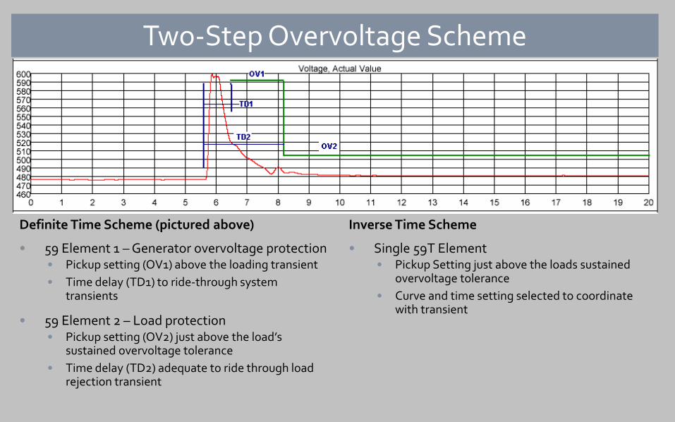
Two-Step Overvoltage Scheme
Definite Time Scheme (pictured above)
• 59 Element 1 – Generator overvoltage protection• Pickup setting (OV1) above the loading transient• Time delay (TD1) to ride-through system
transients
• 59 Element 2 – Load protection• Pickup setting (OV2) just above the load’s
sustained overvoltage tolerance• Time delay (TD2) adequate to ride through load
rejection transient
Inverse Time Scheme
• Single 59T Element• Pickup Setting just above the loads sustained
overvoltage tolerance• Curve and time setting selected to coordinate
with transient

Loading Transients - Frequency
• Abnormal frequency typically not damaging to engine or generator
• 81 element may be desirable to protect load from sustained over-or under excitation
• Settings should coordinate with load shedding schemes

Transformer InrushEmergency Systems with 10-second Requirement First generator on bus energizes multiple transformers Inrush behavior is probabilistic Standard rule of thumb for coordination:
20 X FLA @ 1 cycle 12 X FLA @ 6 cycles.
With high source Z, magnitude may be reduced and duration extended. CT saturation due to DC component of inrush can produce:
False differential current False negative sequence current False residual current

Mitigating Transformer Inrush Trips • Increase CT accuracy: Ratio and core cross section• Match bus and neutral side CTs and lead lengths• Block affected elements for a short period following breaker closure• Increase slope of percentage differential elements (minimal benefit)• 2nd harmonic blocking – typically available in transformer relays, not
universally in generator relays• Use a relay with a CT saturation detection algorithm that blocks
elements or increases settings Directional comparison of bus and neutral currents Increase in restraint current without corresponding increase in operate
current.

Transformer Inrush Event #1

Transformer Inrush Event #2

Selective Coordination• National Electrical Code Requirements
Emergency (700.32) and Legally-Required Standby (701.27) Systems: Selective over the full range of fault currents
Health Care Essential Power Systems (517.31(G)): Selective above 0.1 second clearing time (overload range).
Generator(s) must provide adequate fault current to clear downstream circuit breakers and fuses. Permanent Magnet Generator (PMG) Exciter Static Exciter with Power Current “Boost” Transformers
Equipment specifications and industry “standard”: 2.5 to 3.0 PU for 10 seconds.

Alternator Short Circuit Characteristics

Alternator Short Circuit CharacteristicsDecrement curves based only on data sheet reactances and time constants will not accurately represent the sustained fault current

Coordination with Downstream Fuses
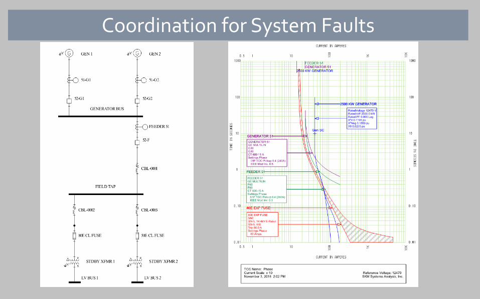
Coordination for System Faults

Backfeeding the Normal Power System If adequate generator capacity, many
facilities want to resume full normal operation during a utility interruption
Considerations when re-energizing normal power feeders from generation: Larger transformers – higher inrush Impact of normal system faults on
emergency loads Coordination with normal feeder relays Preservation of the generators to serve the
standby loads
Same considerations (other than inrush current) apply when running generation in parallel for testing or peak shaving

Intertie Protection Relay Functions
• Traditional (ANSI) Relay Elements Primary Utility Fault Protection (21, 67, 67N) Backup Utility Fault Protection (27, 51, 51N) Loss-of-Outlet (27, 59, 81) Synchronism Check (25C) Reverse Power (32) Backup Protection for Internal Faults (51,
51N)
• Logic Functions Dead Bus Closure Internal Lockout Relay Enable Elements only on Parallel

Considerations for Intertie Protection
• IEEE 1547 – Interconnection and Operability of Distributed Energy Resources with Associated Electric Power Systems Interfaces
• Standby System Considerations Distribution System Interconnections
Slower utility fault clearing Upstream reclosing
Preservation of the standby mission High-speed tripping of utility intertie Typically no ride-through or voltage support required
Loss of outlet (islanding) protection Synchronizing under load

Typical Distribution Interconnection• Upstream Reclosing Opportunities
Transmission Substation Bus Tie Distribution Feeder
• Islanding external to facility not detected by generator controls
• Loss of Outlet Protection Generator in Droop or Load Control Mismatched kW ⇒ ∆f Mismatched kVAR ⇒ ∆V
• Detected by 27/59 and 81 settings Tight window Short delay Unsuitable for normal (non-parallel) operation

Intertie Breaker Tripping Logic

Synchronism Check Criteria - Generator
• Limit transient current
• ANSI/IEE C37.102: Frequency Difference: 0.067 Hz Voltage Difference: + 5% Phase Angle Difference: +/- 10º
• One Engine-Generator Manufacturer’s Recommendation: Frequency Difference: 0.6 Hz Voltage Difference: 1 % Phase Angle Difference: 10º
αsin"xVI
dkW =
xVI
dkVAR "
∆=

Synchronism Check Criteria - Utility• IEEE 1547 Table 5:
• Maximum 5% voltage fluctuation on utility system• Meet prevailing requirements for voltage flicker
Conclusion• Standby systems are increasingly using larger generators with utility
parallel connections• Microprocessor based relays provide opportunities for enhanced
protection and functionality for these applications• Complex relaying also presents a risk of nuisance tripping resulting in
lower overall system reliability• Relay elements and settings must be selected to account for:
Differences between engine-drive and turbine drive characteristics Block loading and load rejection Transformer inrush currents Distribution level interconnections Preservation of the standby mission
• Proper consideration of these factors will provide effective protection without compromising reliability

![[PPT]MAIN CONTROLS OF STEAM TURBINE (LARGE …wbpdclewf.org.in/.../uploads/2016/09/Utility-Turbines.ppt · Web viewAutomatic reset of program after a fault. Automatic Turbine Tester](https://img.pdfslide.us/doc/110x75/5ab192d87f8b9a7e1d8ca5a5/pptmain-controls-of-steam-turbine-large-viewautomatic-reset-of-program-after.jpg)