Embed Size (px)
Citation preview
Protective Devices Maintenance as it Applies to the Arc/FlashHazard
By Dennis K. Neitzel, CPEDirector, AVO Training Institute
One of the key components of the Flash Hazard Analysis, which is required by NFPA 70E-2000, Part II, paragraph 2-1.3.3, is the clearing time of the protective devices, primarilycircuit breakers and protective relays. Fuses, although they are protective devices, do nothave operating mechanisms that would require periodic maintenance; therefore, this articlewill not address them. The primary focus of this article will be the maintenance issues forcircuit breakers and protective relays.
Molded case and low-voltage power circuit breakers (600-volts or less) will generally clear afault condition in 3 to 8 cycles. To be conservative a clearing time of 8 cycles should beused. The majority of older medium-voltage circuit breakers (2300-volts or greater) willclear a fault in around 8 cycles with the newer ones clearing in 3 to 5 cycles. Protectiverelays will generally add approximately 3 to 4 cycles to the clearing time of the mediumcircuit breaker. Where proper maintenance and testing are not performed, extended clearingtimes could occur creating an unintentional time delay that will effect the results of flashhazard analysis.
All maintenance and testing of the electrical protective devices addressed in this article mustbe accomplished in accordance with the manufacturer’s instructions. The NETA“Maintenance Testing Specifications for Electrical Power Distribution Equipment andSystems” 2001 Edition is an excellent source of information for performing the requiredmaintenance and testing of these devices. Visit the NETA website for more information athttp://www.netaworld.org.
This article will address some of the issues concerning proper maintenance and testing ofthese protective devices, according to the manufacturer’s instructions. It will also addresshow protective device maintenance relates to the electrical arc/flash hazard.
Molded-Case Circuit Breakers
Generally, maintenance on molded-case circuit breakers is limited to proper mechanicalmounting, electrical connections, and periodic manual operation. Most lighting, appliance,and power panel circuit breakers have riveted frames and are not designed to be opened forinternal inspection or maintenance. All other molded-case circuit breakers that are ULapproved are factory-sealed to prevent access to the calibrated elements. An unbroken sealindicates that the mechanism has not been tampered with and that it should function asspecified by UL. A broken seal voids the UL listing and the manufacturers’ warranty of thedevice. In this case, the integrity of the device would be questionable. The only exception tothis would be a seal being broken by a manufacturer’s authorized facility.
Molded-case circuit breakers receive extensive testing and calibration at the manufacturers’plants. These tests are performed in accordance with UL 489, Standard for Safety, Molded-Case Circuit Breakers, Molded-Case Switches and Circuit Breaker Enclosures. Molded-casecircuit breakers, other than the riveted frame types, are permitted to be reconditioned andreturned to the manufacturer’s original condition. In order to conform to the manufacturer’soriginal design, circuit breakers must be reconditioned according to recognized standards.The Professional Electrical Apparatus Recyclers League (PEARL) companies follow rigidstandards to recondition low-voltage industrial and commercial molded-case circuit breakers.It is highly recommended that only authorized professionals recondition molded-case circuitbreakers. Visit the PEARL website for more information at http://www.pearl1.org.Circuit breakers installed in a system are often forgotten. Even though the breakers havebeen sitting in place supplying power to a circuit for years, there are several things that cango wrong. The circuit breaker can fail to open due to a burned out trip coil or because themechanism is frozen due to dirt, dried lubricant, or corrosion. The overcurrent device can faildue to inactivity or a burned out electronic component. Many problems can occur whenproper maintenance is not performed and the breaker fails to open under fault conditions.This combination of events can result in fires, damage to equipment or injuries to personnel.
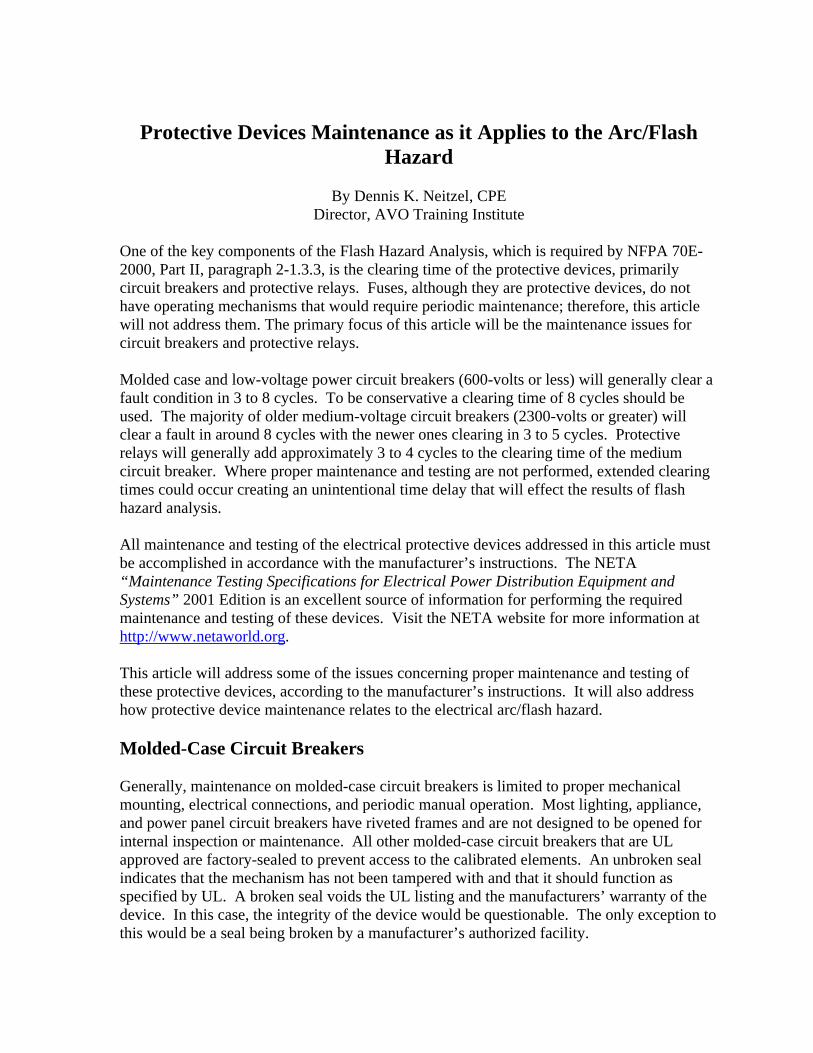
All too often, a circuit breaker fails because the minimum maintenance (as specified by themanufacturer) was not performed or was performed improperly. Small things, like failing toproperly clean and/or lubricate a circuit breaker, can lead to operational failure or completedestruction due to overheating of the internal components. Common sense, as well asmanufacturers’ literature, must be used when maintaining circuit breakers. Mostmanufacturers, as well as NFPA 70B, recommend that if a molded-case circuit breaker hasnot been operated, opened or closed, either manually or by automatic means, within as littleas six months time, it should be removed from service and manually exercised several times.This manual exercise helps to keep the contacts clean due to their wiping action and ensuresthat the operating mechanism moves freely. This exercise however does not operate themechanical linkages in the tripping mechanism (Figure 1). The only way to properlyexercise the entire breaker operating and tripping mechanisms is to remove the breaker fromservice and test the overcurrent and short-circuit tripping capabilities. A stiff or stickymechanism can cause an unintentional time delay in its operation under fault conditions.This could dramatically increase the arc/flash incident energy level to a value in excess of therating of personal protective equipment. There will be more on incident energy later in thisarticle.
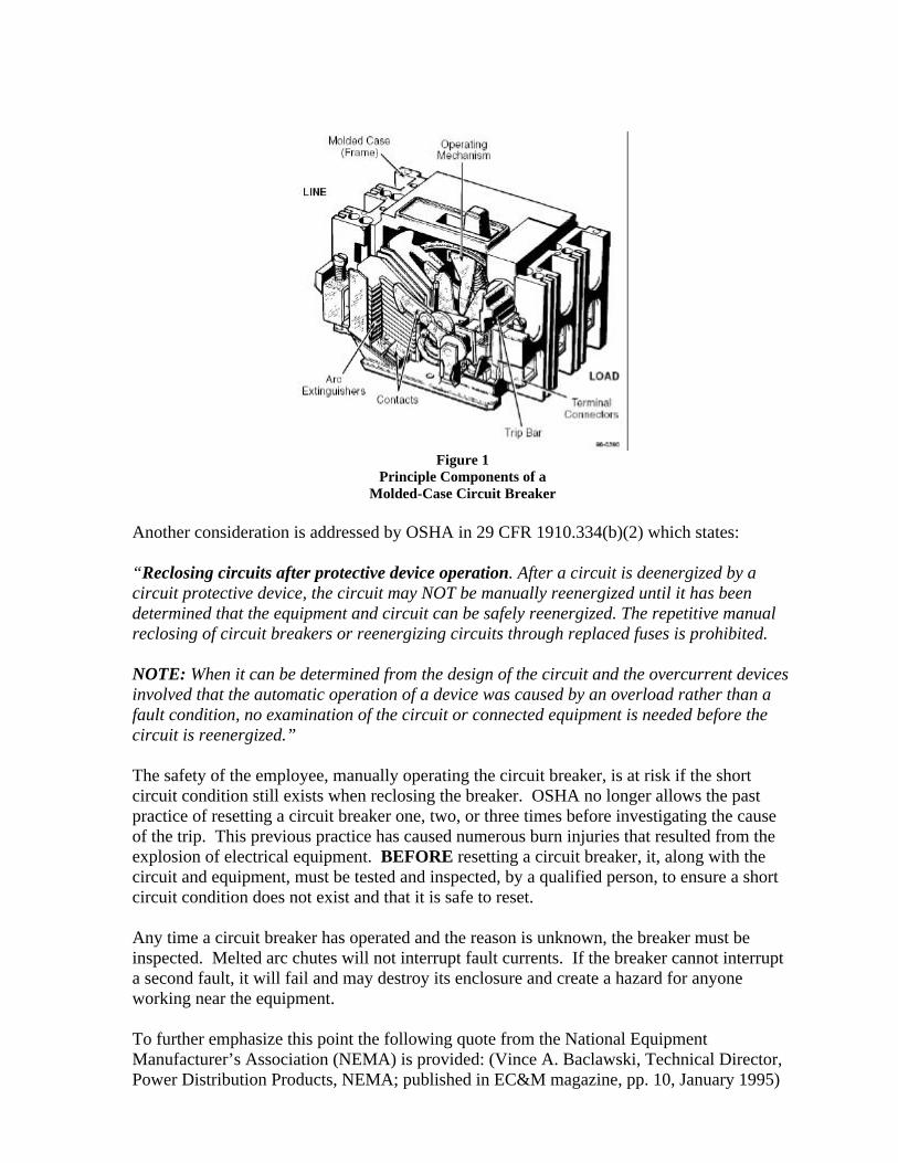
Figure 1Principle Components of a
Molded-Case Circuit Breaker
Another consideration is addressed by OSHA in 29 CFR 1910.334(b)(2) which states:
“Reclosing circuits after protective device operation. After a circuit is deenergized by acircuit protective device, the circuit may NOT be manually reenergized until it has beendetermined that the equipment and circuit can be safely reenergized. The repetitive manualreclosing of circuit breakers or reenergizing circuits through replaced fuses is prohibited.
NOTE: When it can be determined from the design of the circuit and the overcurrent devicesinvolved that the automatic operation of a device was caused by an overload rather than afault condition, no examination of the circuit or connected equipment is needed before thecircuit is reenergized.”
The safety of the employee, manually operating the circuit breaker, is at risk if the shortcircuit condition still exists when reclosing the breaker. OSHA no longer allows the pastpractice of resetting a circuit breaker one, two, or three times before investigating the causeof the trip. This previous practice has caused numerous burn injuries that resulted from theexplosion of electrical equipment. BEFORE resetting a circuit breaker, it, along with thecircuit and equipment, must be tested and inspected, by a qualified person, to ensure a shortcircuit condition does not exist and that it is safe to reset.
Any time a circuit breaker has operated and the reason is unknown, the breaker must beinspected. Melted arc chutes will not interrupt fault currents. If the breaker cannot interrupta second fault, it will fail and may destroy its enclosure and create a hazard for anyoneworking near the equipment.
To further emphasize this point the following quote from the National EquipmentManufacturer’s Association (NEMA) is provided: (Vince A. Baclawski, Technical Director,Power Distribution Products, NEMA; published in EC&M magazine, pp. 10, January 1995)
“After a high level fault has occurred in equipment that is properly rated andinstalled, it is not always clear to investigating electricians what damage has occurred insideencased equipment. The circuit breaker may well appear virtually clean while its internalcondition is unknown. For such situations, the NEMA AB4 ‘Guidelines for Inspection andPreventive Maintenance of MCCBs Used in Commercial and Industrial Applications’ may beof help. Circuit breakers unsuitable for continued service may be identified by simpleinspection under these guidelines. Testing outlined in the document is another and moredefinite step that will help to identify circuit breakers that are not suitable for continuedservice.
After the occurrence of a short circuit, it is important that the cause be investigatedand repaired and that the condition of the installed equipment be investigated. A circuitbreaker may require replacement just as any other switching device, wiring or electricalequipment in the circuit that has been exposed to a short circuit. Questionable circuitbreakers must be replaced for continued, dependable circuit protection.”
The condition of the circuit breaker must be known to ensure that it functions properly andsafely before it is put it back into service.
Low-Voltage Power Circuit Breakers
Low-voltage power circuit breakers are manufactured under a high degree of quality control,of the best materials available, and with a high degree of tooling for operational accuracy.Manufacturer’s tests show these circuit breakers to have durability beyond the minimumstandards requirements. All of these factors give these circuit breakers a very high reliabilityrating. However, because of the varying application conditions and the dependence placedupon them for protection of electrical systems and equipment as well as the assurance ofservice continuity, inspections and maintenance checks must be made on a regular basis.Several studies, including IEEE, have shown that low-voltage power circuit breakers, whichwere not maintained within a 5-year period, have a 50% failure rate.
Maintenance of these breakers will generally consist of keeping them clean and properlylubricated. The frequency of maintenance will depend to some extent on the cleanliness ofthe surrounding area. If there were very much dust, lint, moisture, or other foreign matterpresent then obviously more frequent maintenance would be required.
Industry standards for, as well as manufacturers of, low-voltage power circuit breakersrecommend a general inspection and lubrication after a specified number of operations or atleast once per year, whichever comes first. Some manufacturers also recommend this sameinspection and maintenance be performed after the first six months of service regardless ofthe number of operations. If the breaker remains open or closed for a long period of time, itis recommended that arrangements be made to open and close the breaker several times insuccession, preferably under load conditions. Environmental conditions play a major role inthe scheduling of inspections and maintenance. If the initial inspection indicates thatmaintenance is not required at that time, the period may be extended to a more economicalpoint. However, more frequent inspections and maintenance may be required if severe loadconditions exist or if an inspection reveals heavy accumulations of dirt, moisture, or other
foreign matter that might cause mechanical, insulation, or electrical failure. Mechanicalfailure would include an unintentional time delay in the circuit breakers tripping operationdue to dry, dirty or corroded pivot points or by hardened or sticky lubricant in the movingparts of the operating mechanism. The manufacturer’s instructions must be followed in orderto minimize the risk of any unintentional time delay.
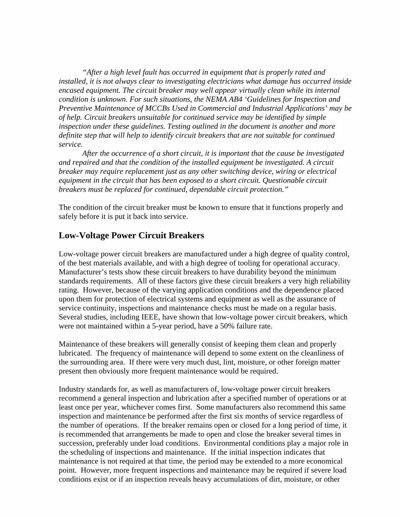
Figure 2 provides an illustration of the numerous points where lubrication would be requiredand where dirt, moisture, corrosion or other foreign matter could accumulate causing a timedelay in, or complete failure of, the circuit breaker operation.
Figure 2Power-Operated Mechanism of a
Cutler/Hammer “DS” Circuit Breaker
Medium-Voltage Power Circuit Breakers
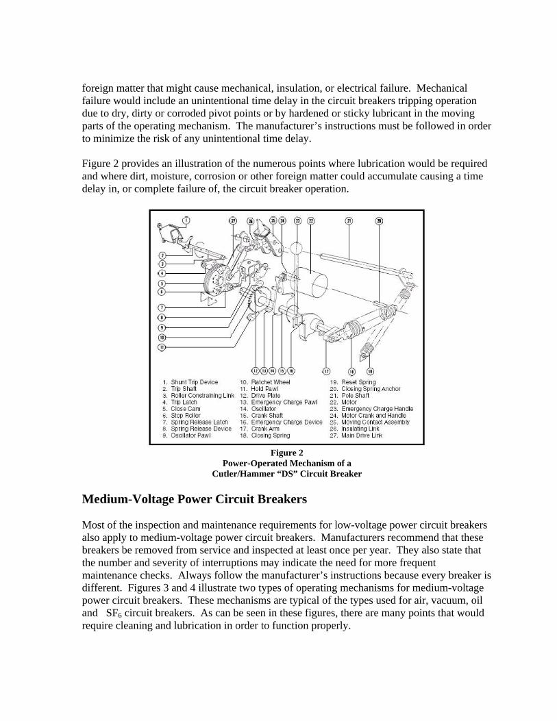
Most of the inspection and maintenance requirements for low-voltage power circuit breakersalso apply to medium-voltage power circuit breakers. Manufacturers recommend that thesebreakers be removed from service and inspected at least once per year. They also state thatthe number and severity of interruptions may indicate the need for more frequentmaintenance checks. Always follow the manufacturer’s instructions because every breaker isdifferent. Figures 3 and 4 illustrate two types of operating mechanisms for medium-voltagepower circuit breakers. These mechanisms are typical of the types used for air, vacuum, oiland SF6 circuit breakers. As can be seen in these figures, there are many points that wouldrequire cleaning and lubrication in order to function properly.
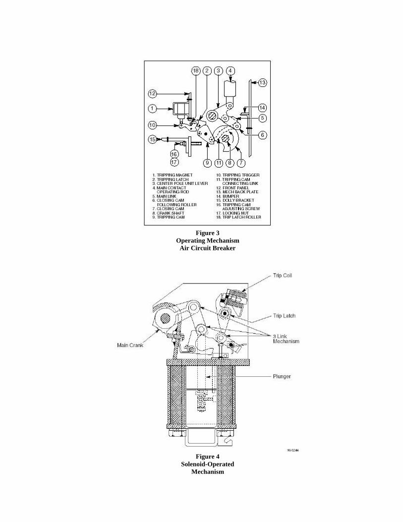
Figure 3Operating Mechanism
Air Circuit Breaker
Figure 4Solenoid-Operated
Mechanism
Protective Relays
Relays must continuously monitor complex power circuit conditions, such as current andvoltage magnitudes, phase angle relationships, direction of power flow, and frequency.When an intolerable circuit condition, such as a short circuit (or fault) is detected, the relayresponds and closes its contacts, and the abnormal portion of the circuit is deenergized viathe circuit breaker. The ultimate goal of protective relaying is to disconnect a faulty systemelement as quickly as possible. Sensitivity and selectivity are essential to ensure that theproper circuit breakers are tripped at the proper speed to clear the fault, minimize damage toequipment, and to reduce the hazards to personnel.
A clear understanding of the possible causes of primary relaying failure is necessary for abetter appreciation of the practices involved in backup relaying. One of several things mayhappen to prevent primary relaying from disconnecting a power system fault:
• Current or voltage supplies to the relays are incorrect.• DC tripping voltage supply is low or absent.• Protective relay malfunctions.• Tripping circuit or breaker mechanism hangs up.
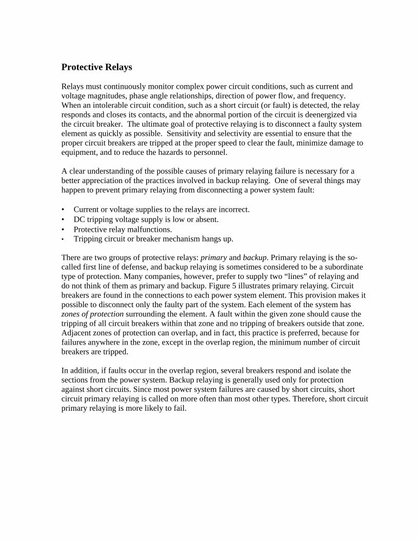
There are two groups of protective relays: primary and backup. Primary relaying is the so-called first line of defense, and backup relaying is sometimes considered to be a subordinatetype of protection. Many companies, however, prefer to supply two “lines” of relaying anddo not think of them as primary and backup. Figure 5 illustrates primary relaying. Circuitbreakers are found in the connections to each power system element. This provision makes itpossible to disconnect only the faulty part of the system. Each element of the system haszones of protection surrounding the element. A fault within the given zone should cause thetripping of all circuit breakers within that zone and no tripping of breakers outside that zone.Adjacent zones of protection can overlap, and in fact, this practice is preferred, because forfailures anywhere in the zone, except in the overlap region, the minimum number of circuitbreakers are tripped.
In addition, if faults occur in the overlap region, several breakers respond and isolate thesections from the power system. Backup relaying is generally used only for protectionagainst short circuits. Since most power system failures are caused by short circuits, shortcircuit primary relaying is called on more often than most other types. Therefore, short circuitprimary relaying is more likely to fail.
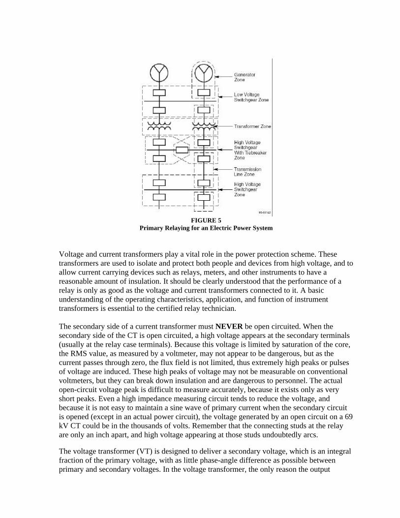
FIGURE 5Primary Relaying for an Electric Power System
Voltage and current transformers play a vital role in the power protection scheme. Thesetransformers are used to isolate and protect both people and devices from high voltage, and toallow current carrying devices such as relays, meters, and other instruments to have areasonable amount of insulation. It should be clearly understood that the performance of arelay is only as good as the voltage and current transformers connected to it. A basicunderstanding of the operating characteristics, application, and function of instrumenttransformers is essential to the certified relay technician.
The secondary side of a current transformer must NEVER be open circuited. When thesecondary side of the CT is open circuited, a high voltage appears at the secondary terminals(usually at the relay case terminals). Because this voltage is limited by saturation of the core,the RMS value, as measured by a voltmeter, may not appear to be dangerous, but as thecurrent passes through zero, the flux field is not limited, thus extremely high peaks or pulsesof voltage are induced. These high peaks of voltage may not be measurable on conventionalvoltmeters, but they can break down insulation and are dangerous to personnel. The actualopen-circuit voltage peak is difficult to measure accurately, because it exists only as veryshort peaks. Even a high impedance measuring circuit tends to reduce the voltage, andbecause it is not easy to maintain a sine wave of primary current when the secondary circuitis opened (except in an actual power circuit), the voltage generated by an open circuit on a 69kV CT could be in the thousands of volts. Remember that the connecting studs at the relayare only an inch apart, and high voltage appearing at those studs undoubtedly arcs.
The voltage transformer (VT) is designed to deliver a secondary voltage, which is an integralfraction of the primary voltage, with as little phase-angle difference as possible betweenprimary and secondary voltages. In the voltage transformer, the only reason the output
voltage per turn is less than the input voltage per turn is because of losses through resistanceand reactance (impedance).
Some overcurrent relays are equipped with an instantaneous overcurrent unit, which operateswhen the current reaches its minimum pickup point (see Figure 6). An instantaneous unit is arelay having no intentional time delay. Should an overcurrent of sufficient magnitude beapplied to the relay, both the induction disc and the instantaneous unit will operate. However,the instantaneous unit will trip the circuit breaker, since it has no intentional time delay. InFigure 6, the operating coil is in the AC portion of the relay in series with the induction coil.The contacts are directly across the trip circuit and the spiral spring is never involved in thetripping action.
FIGURE 6Instantaneous Trip Unit
The instantaneous trip unit is a small, AC-operated clapper device. A magnetic armature, towhich leaf-spring-mounted contacts are attached, is attracted to the magnetic core uponenergization. When the instantaneous unit closes, the moving contacts bridge two stationarycontacts and complete the trip circuit. The core screw, accessible from the top of the unit,provides the adjustable pickup range. Newer designs also feature tapped coils to allow evengreater ranges of adjustment.
The instantaneous unit, like the ICS unit, is equipped with an indicator target. This indicationshows that the relay has operated. It is important to know which relay has operated, and norelay target should be reset without the supervisor’s knowledge and permission.
As can be seen, several things can go wrong that would prevent the instantaneous unit fromoperating properly. These things include an open or shunted current transformer, open coil,or dirty contacts. Protective relays, like circuit breakers, require periodic inspection,maintenance, and testing to function properly. Most manufacturers recommend that periodicinspections and maintenance be performed at intervals of one to two years. The intervals

between periodic inspection and maintenance will vary depending upon environment, type ofrelay, and the user’s experience with periodic testing.
The periodic inspections, maintenance, and testing are intended to ensure that the protectiverelays are functioning properly and have not deviated from the design settings. If deviationsare found, the relay must be retested and serviced as described in the manufacturer’sinstructions.
Flash Hazard Analysis
As noted at the beginning of this article, NFPA 70E-2000, Part II, paragraph 2-1.3.3 requiresa flash hazard analysis be performed before anyone approaches exposed electrical conductorsor circuit parts that have not been placed in an electrically safe work condition. In addition,Paragraph 2-1.3.3.2 requires a flash protection boundary to be established. All calculationsfor determining the incident energy of an arc and for establishing a flash protection boundaryrequire the arc clearing time. This clearing time is derived from the engineering coordinationstudy, which is based on what the protective devices are supposed to do.
Maintenance is a very critical part of the flash hazard issue. The information provided in thisarticle clearly indicates the need for a preventive maintenance program on these circuitprotective devices. Evidence has proven that inadequate maintenance can causeunintentional time delays in the clearing of a short circuit condition. If, for example, a low-voltage power circuit breaker had not been operated or maintained for several years and thelubrication had become sticky or hardened, the circuit breaker could take several additionalcycles, seconds, minutes, or longer to clear a fault condition. The following is a specificexample:
If a Flash Hazard Analysis is performed based on what the system is suppose to do, let’s say5 cycle clearing time, and there is an unintentional time delay, due to a sticky mechanism,and the breaker clears in 30 cycles, the worker could be seriously injured or killed becausehe/she was under protected.
If the calculation is performed for a 20,000-amp fault, 480 volts, 3-inch arc gap, the worker is18 inches from the arc, with a 5 cycle clearing time for a 3-phase arc in a box (enclosure), theresults would be approximately 6.5 cal/cm2 which would require an Arc/Flash Category 2protection based on NFPA 70E-2000, Part II, Table 3-3.9.3.
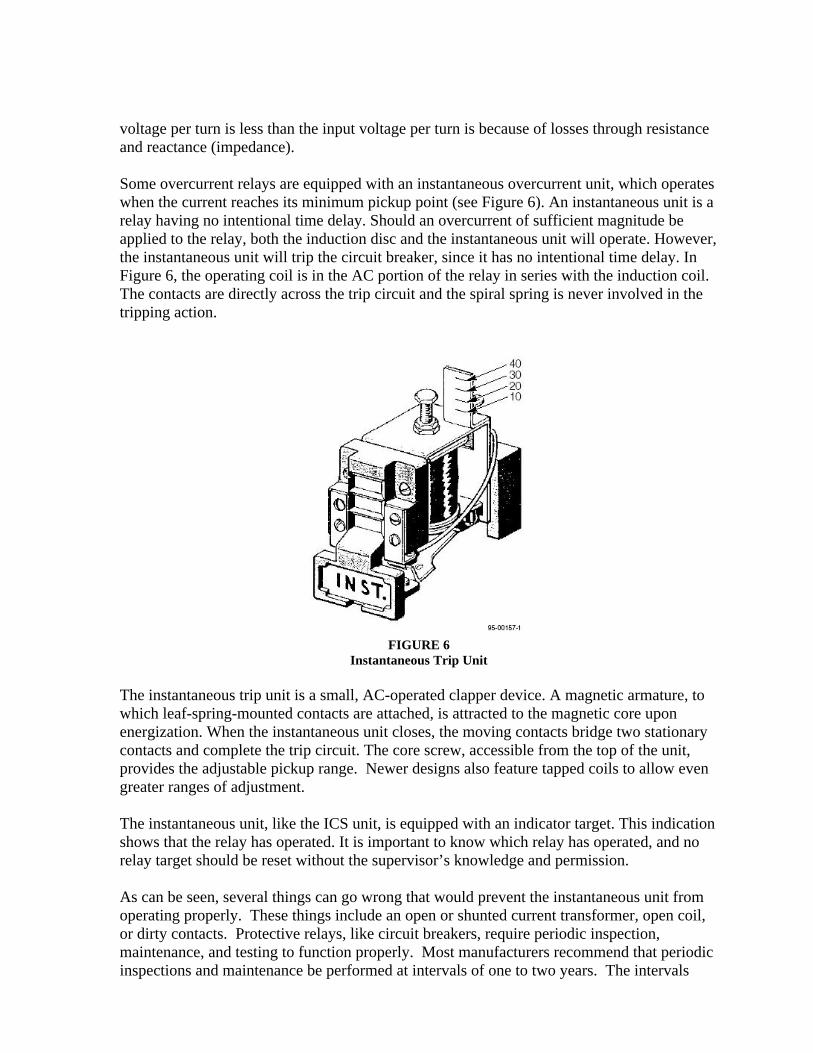
The following example (Figure 7) uses the Heat Flux Calculator (developed by AlanPrivette) and the values above for a 5 cycle clearing time:
FIGURE 7
Calculation with a 5 Cycle Clearing Time
This value of 1.89431 cal/cm2 is based on a single-phase arc in open-air. As a general rule ofthumb, the value of 1.89431 would be multiplied by a factor of 2 for a single-phase arc in abox (2 x 1.89431 = 3.78862 cal/cm2 – Category 1) and by a factor of 3.4 for a multi-phase arcin a box (3.4 x 1.89431 = 6.440654 cal/cm2 – Category 2).
If the clearing time is increased to 30 cycles (Figure 8) then the results are approximately38.7 cal/cm2, which requires an Arc/Flash Category 4 protection.
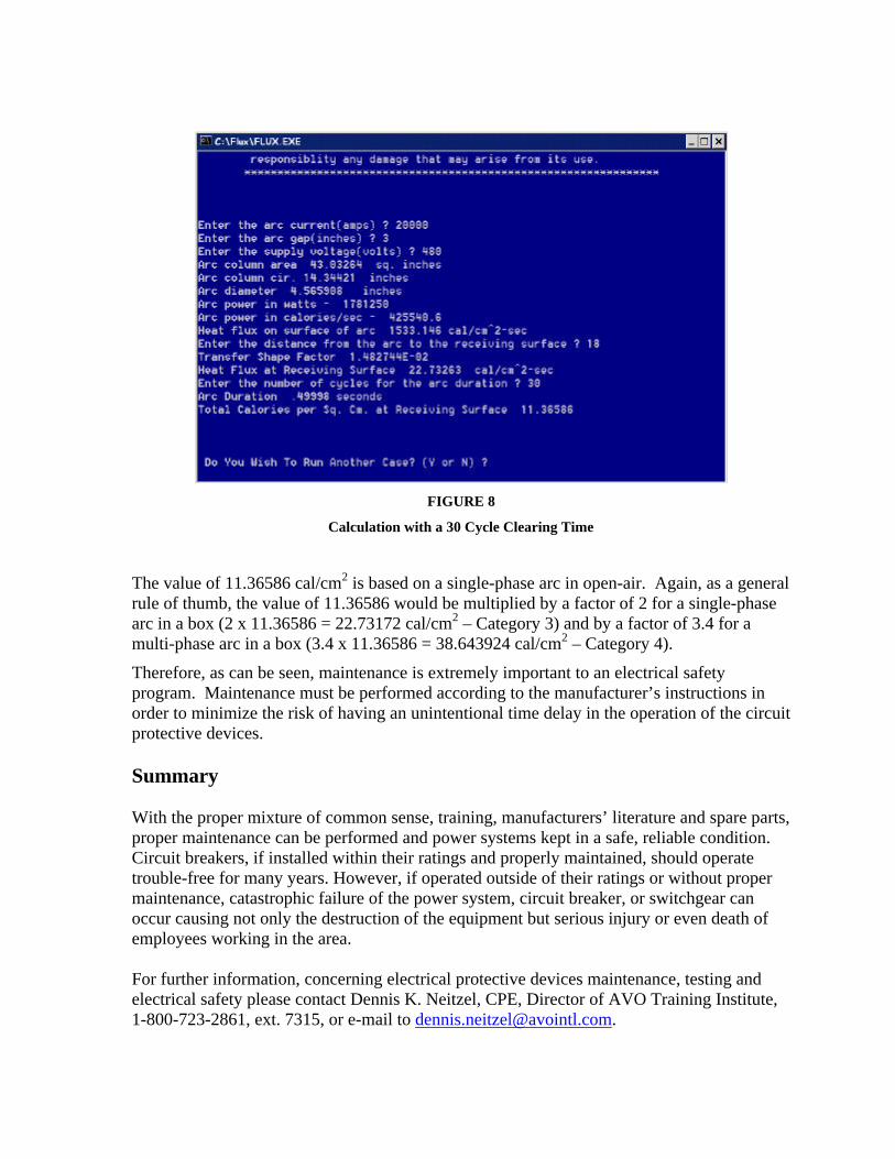
FIGURE 8
Calculation with a 30 Cycle Clearing Time
The value of 11.36586 cal/cm2 is based on a single-phase arc in open-air. Again, as a generalrule of thumb, the value of 11.36586 would be multiplied by a factor of 2 for a single-phasearc in a box (2 x 11.36586 = 22.73172 cal/cm2 – Category 3) and by a factor of 3.4 for amulti-phase arc in a box (3.4 x 11.36586 = 38.643924 cal/cm2 – Category 4).
Therefore, as can be seen, maintenance is extremely important to an electrical safetyprogram. Maintenance must be performed according to the manufacturer’s instructions inorder to minimize the risk of having an unintentional time delay in the operation of the circuitprotective devices.
Summary
With the proper mixture of common sense, training, manufacturers’ literature and spare parts,proper maintenance can be performed and power systems kept in a safe, reliable condition.Circuit breakers, if installed within their ratings and properly maintained, should operatetrouble-free for many years. However, if operated outside of their ratings or without propermaintenance, catastrophic failure of the power system, circuit breaker, or switchgear canoccur causing not only the destruction of the equipment but serious injury or even death ofemployees working in the area.
For further information, concerning electrical protective devices maintenance, testing andelectrical safety please contact Dennis K. Neitzel, CPE, Director of AVO Training Institute,1-800-723-2861, ext. 7315, or e-mail to [email protected].