Embed Size (px)
Citation preview
Protection Technology GroupApplications GuideWhite Paper
Protection Technology Group Applications Guide 1
Protection Technology Group Applications Guide
RF. AC. DC and Data Line surge protectors are used to protect critical communication assets in a variety of applications and markets. The following information is created to help explain terminology commonly used in today’s surge protection industry.
AC Power ProtectorsPower main protectors are to be placed at entrance panels, transfer switches and distribution panels. They should have a low inductance path to the earth system. For best protection, have an additional in-line power protector at or near the sensitive equipment.
Combiner ProtectorsCombining consists of summing multiple channels together to feed onto a common cable. Low frequencies and higher frequencies will in time reach a peak voltage together with the same polarity. This voltage summation peak can have more peak power than the sum of their RMS power.
DC Injector/DC PathProtects active antennas, pre-amps or other situations requiring a dc (or ac) voltage on the center conductor. The dc and RF paths (the RF is dc-blocked) are separated, individually protected, and recombined. The bias-T models are for injecting the dc onto the center conductor or picking off the dc to feed a powered device.
DC Power ProtectorsUsed in solar power and other dc current systems. The open circuit voltage of the battery must be less than the turn-on voltage value of the protector.
DATA/Phone Line ProtectorsTelephone central offices and computer rooms have components in common. Both have computers connected to data or phone lines, local area networks (LAN), and phone channel banks (T-carries). All are interconnected to the outside world with twisted pair, coaxial cable, or fiber optic interfaces.
Telephone central offices and computer rooms have much in common. Both have computers connected to data or phone lines, local area networks LAN, and phone channel banks (T-carrier). All are interconnected to the “outside world” with twisted pair coaxial cable or fiber optic interfaces.
Telephone line protectors supplied by the phone company are a first line of defense, but are not always connected to a high current capacity, fast transient response ground system. PolyPhaser offers a series of data and Telco protectors when a higher level of protection is required.
LAN and T-carriers require protectors that have wide bandwidths for high frequency data with tightly controlled surge energy specifications. If our catalog products do not match your requirement, we can supply a custom designed product for your application.
Other special protectors are available for Telco span line and repeater current loop lines.
2
1457-012
RF Coupled Shield/DC BlockedProvides the ultimate in protection. Both the center conductor and the shield are dc blocked. Useful when the capability of the ground system to handle the surge is either inadequate or questionable. Also prevents ground loops and achieves the proper single point ground.
DC Blocked FilterUsed with passive (no pre-amp) antennas. These will NOT pass dc (or 50/60Hz ac) voltage(s) duplexed onto the center conductor. They provide maintenance-free service and the industry’s lowest throughput energy.
DC Blocked/Gas TubeUsed with passive (no pre-amp) antennas. These will NOT pass dc (or 50/60Hz ac) voltage(s) duplexed onto the center conductor for feeding pre-amps, relays or sequencers. Use these in single transmitter situations only. If combiners are used, a combiner protector should be specified.
DC Type & Isolated ShieldFor coax-based baseband LANs (e.g. 10/100 BASE T), closed circuit television (CCTV) security monitors, and HF receive only. To prevent ground loop hum problems, use IGA-90V to isolate the shield of the mounted protector from each ground.
Grounding Components
Bulkhead to Flange Adapter (BFN, BFD)Adapts most PolyPhaser bulkhead-mounted protectors to mount on a single point grounding panel or similar flat surface. The connector on the antenna (surge) side must be female; i.e. will not work with the -MA versions.
Low Inductance Copper Grounding Strap (CS112-, CS3-, and CS6-)To achieve a low inductance ground system. Copper strap has a larger surface area and lower inductance per foot than equivalent cross section circular wire. CS112 (1.5in), CS3 (3 in), CS6 (6 in)
Copper Strap Bonding Clamps (1C-112S, MSC-3)To bond copper strap without building up the joint for an exothermic weld. Use for connect the copper strap radial to the ground rod; to transition from copper strap to wire [sizes #6AWG to #4/0AWG], and bonding different widths of copper strap to each other.
Copper to Tower Leg Corrosion Free Grounding Clamps (TK-(1 to 4))Used for attaching copper strap to a galvanized tower leg. Maximizes the contact surface area and prevents corrosion due to dissimilar metals. This eliminates the need for exothermic welding to the tower.
Protection Technology Group Applications Guide 3
Wire/Copper Rod Transition Clamps (J-1, J-2)Bonds the copper strap radial to the (copper-plated) ground rod without building up the joint for an exothermic weld.
Copper Cleaning Kit and Copper Primer Kit (CCK)For best results, copper should be brought down to “white metal” before bonding and weather sealing. To paint the copper straps and entrance panels use copper primer kit.
Weather Proofing Kit (WK-1)When a PolyPhaser model designed for inside use must be mounted outdoors and unprotected from the elements use the weather proofing kit to prevent moisture ingress. The kit can easily handle extreme temperatures, and is unaffected by the sun’s ultra-violet (UV) rays.
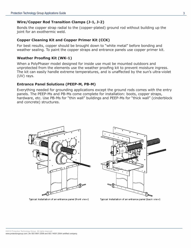
Entrance Panel Solutions (PEEP-M, PB-M)Everything needed for grounding applications except the ground rods comes with the entry panels. The PEEP-Ms and PB-Ms come complete for installation: boots, copper straps, hardware, etc. Use PB-Ms for “thin wall” buildings and PEEP-Ms for “thick wall” (cinderblock and concrete) structures.
4
1457-012
PolyPhaser’s Coaxial Impulse Suppressors
The Polyphaser Rf Protection DifferencePolyPhaser Corporation’s coaxial impulse suppressors are a unique line of patented products. Hermetically sealed voltage sensitive gas tubes are used on most models with additional components to assure that surge voltages and currents formed differently on the coax are not conducted to the equipment input. There is no dc continuity from center pin to center pin on our dc blocked protectors.
Other gas tube protectors have ac continuity through their center pins and share the energy with the equipment before the gas tube turns on. If the equipment has an inductor to ground as the first component, the differential voltage must first propagate through the coax jumper to the equipment, then create enough inductive voltage drop across the combined inductances (coax cable jumper and input inductor) to turn on the gas tube.
Since the gas tube turn on voltage must be rated above transmitter power (Ep=1.414/PZ), a considerable inductive voltage drop (E-L di/dt) must occur for the gas tube to fire. The voltage required to fire the gas tube is directly related to pulse rise time and current flow through the combined inductances to ground. Typically, 10,000 amps (peak) through the equipment input circuitry to ground is required to develop the L di/dt voltage needed to fire the gas tube in a dc continuity coax protector. The equipment is subject to a 10,000 amp pulse before the protector can turn on!
Quarter wave stub protectors are also dc coupled devices. There is dc continuity between either ends of the center pin used by quarter wave stubs. However, instead of a broad band voltage sensitive device (gas tube), quarter wave stub protectors are a tuned band pass filter. A grounded quarter wave matching section in the device presents high impedance to the center conductor at the designed operating band and a low impedance to ground for all other frequencies. Since most of lightning’s energy is at dc or frequencies up to 1MHz, these types of protectors would appear to be ideal. However, this is not the case.
Antennas are a tuned circuit and will ring at their operating frequency when hit with a fast rise time voltage pulse (lightning). This on frequency ringing voltage will propagate down the coax with other lower lightning frequencies. The quarter wave stub will, at best, divide the lower frequency energies, sending most to ground. Some of the other frequency energy and all of the on frequency energy will go to the equipment input. A gas tube protector on the other hand is voltage sensitive, regardless of frequency, and will conduct the ringing voltage to ground.
A PolyPhaser dc blocked protector lets through low milli-, or micro-joules (very low surge energy) depending on the part’s unique rated design specifications. Comparatively, a PolyPhaser dc blocked protector is much more effective at blocking surge energy than a quarter wave stub. Peak voltage let-through is also significantly less than dc continuity protectors such as a quarter wave stub. PolyPhaser’s measured let-through energy and voltage are the industries lowest.
Protection Technology Group Applications Guide 5
PolyPhaser’s new dc blocked, non gas tube, weather resistant impulse suppressors continue a strong tradition of superior RF surge performance. These new “Microwave Filter” devices with band passes capabilities from 350MHz and up represent the best protection available for communication systems (i.e., CELLULAR, PCS, TETRA, etc) operating in frequencies from 350MHz to 11GHz. Unlike quarter wave stubs, our filter protectors exhibit a wide flat band pass, very low VSWR and insertion loss. With average power level capabilities up to 750 watts, they are the best choice for critical high power applications.
Since PolyPhaser’s Microwave Filters (SX series) are dc blocked (quarter wave stub filters are not), the PolyPhaser filter does not “share” lightning energy with the equipment input.
Peak current ratings on coaxial protectors vary with different manufacturers. A higher peak current rating does not always mean a better protector. For example, consider a self supporting tower with 9 antennas and one microwave down-link for a total of 10 coaxial cables. An average lightning strike induces 20kA of surge current. However, let’s calculate a 100kA strike (less than 1 percent of all strikes). The tower would conduct 70kA to ground. The remaining 30kA is divided between 10 coax cables, or 3kA on each cable. Since most of the peak current is on the shield, about 1 kA would be on the center conductor. When applying the above current division principle to a tower system, it is easy to see why PolyPhaser’s 20kA rating is more than adequate.
Coax Protection
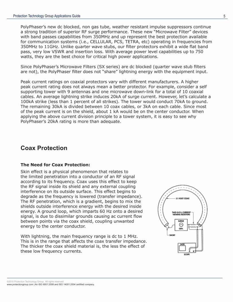
The Need for Coax Protection:Skin effect is a physical phenomenon that relates to the limited penetration into a conductor of an RF signal according to its frequency. Coax uses this effect to keep the RF signal inside its shield and any external coupling interference on its outside surface. This effect begins to degrade as the frequency is lowered (transfer impedance). The RF penetration, which is a gradient, begins to mix the shields outside interference energy with the desired inside energy. A ground loop, which imparts 60 Hz onto a desired signal, is due to dissimilar grounds causing ac current flow between points via the coax shield, coupling unwanted energy to the center conductor.
With lightning, the main frequency range is dc to 1 MHz. This is in the range that affects the coax transfer impedance. The thicker the coax shield material is, the less the effect of these low frequency currents.
6
1457-012
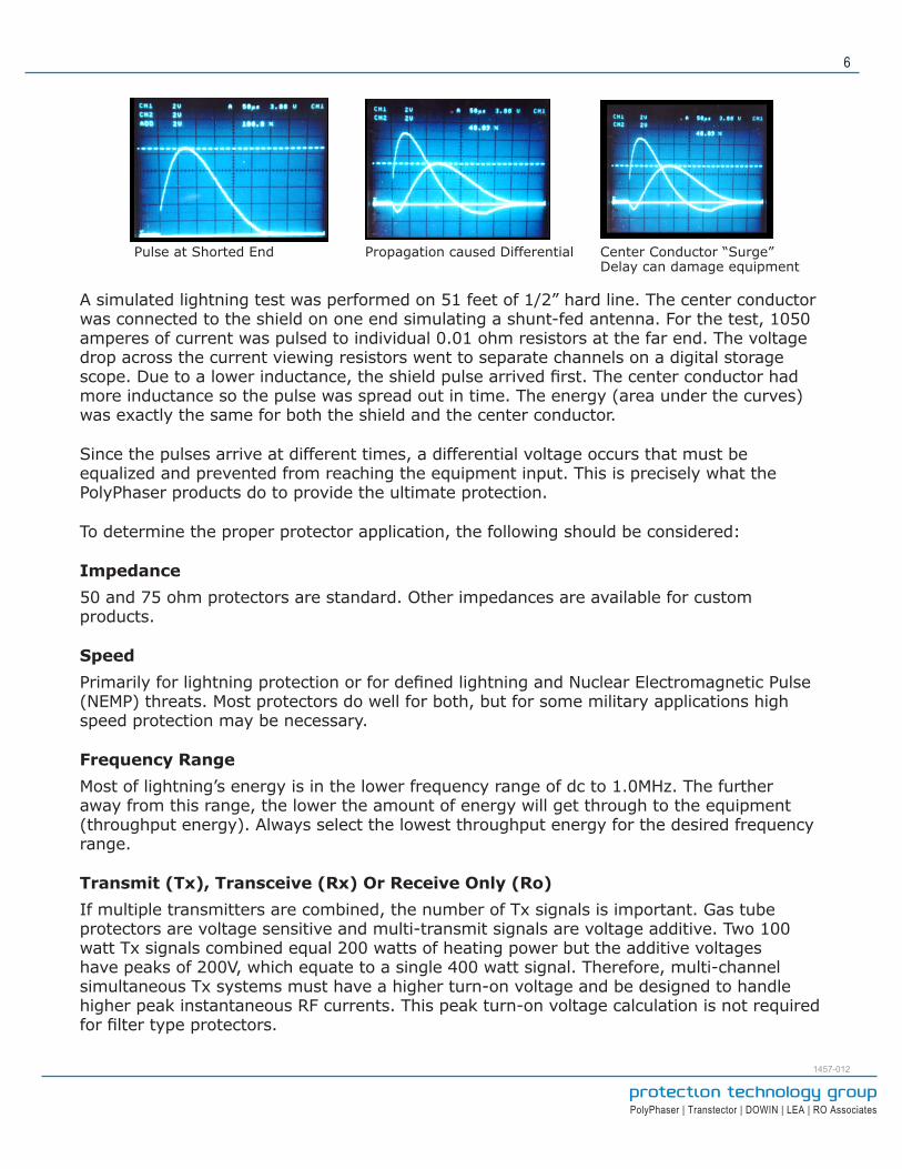
A simulated lightning test was performed on 51 feet of 1/2” hard line. The center conductor was connected to the shield on one end simulating a shunt-fed antenna. For the test, 1050 amperes of current was pulsed to individual 0.01 ohm resistors at the far end. The voltage drop across the current viewing resistors went to separate channels on a digital storage scope. Due to a lower inductance, the shield pulse arrived first. The center conductor had more inductance so the pulse was spread out in time. The energy (area under the curves) was exactly the same for both the shield and the center conductor.
Since the pulses arrive at different times, a differential voltage occurs that must be equalized and prevented from reaching the equipment input. This is precisely what the PolyPhaser products do to provide the ultimate protection.
To determine the proper protector application, the following should be considered:
Impedance50 and 75 ohm protectors are standard. Other impedances are available for custom products.
SpeedPrimarily for lightning protection or for defined lightning and Nuclear Electromagnetic Pulse (NEMP) threats. Most protectors do well for both, but for some military applications high speed protection may be necessary.
Frequency RangeMost of lightning’s energy is in the lower frequency range of dc to 1.0MHz. The further away from this range, the lower the amount of energy will get through to the equipment (throughput energy). Always select the lowest throughput energy for the desired frequency range.
Transmit (Tx), Transceive (Rx) Or Receive Only (Ro)If multiple transmitters are combined, the number of Tx signals is important. Gas tube protectors are voltage sensitive and multi-transmit signals are voltage additive. Two 100 watt Tx signals combined equal 200 watts of heating power but the additive voltages have peaks of 200V, which equate to a single 400 watt signal. Therefore, multi-channel simultaneous Tx systems must have a higher turn-on voltage and be designed to handle higher peak instantaneous RF currents. This peak turn-on voltage calculation is not required for filter type protectors.
Pulse at Shorted End Propagation caused Differential Center Conductor “Surge” Delay can damage equipment
Protection Technology Group Applications Guide 7
Transmit Power (Continuous And/Or Peak)As the frequency is increased in a gas tube type protector, the power handling is reduced. This is done to ensure the protector will turn off after a lightning strike or EMP firing and not be “kept alive” in a glow mode by the presence of the RF transmit energy. The turn-on voltage is determined by the protector power rating. Since most PolyPhaser gas tube units do not have dc continuity, little protection is lost by going to a higher turn-on voltage unit especially if Tx combining is planned in the future. This is not a concern with filter type units (i.e., SX units. SX units do not have gas tubes).
Presence Of AC Or DC Power With The RF SignalsUsed for receive only situations such as tower top preamps and down converters, (“active” antennas).
MountingBulkhead panels systems are listed as grounding components. Flange style may be mounted on a bus bar or a single point ground panel. A ground strap larger than the total sum of all the circumferences of the coax shields should be used to connect to a low inductance ground system.
Connector Type And GenderType N connectors are standard. DIN, TNC, BNC, SMA, and F male and female are stocked connectors. The connector gender can be chosen for male and/or female combinations except for some microwave models. The male connector will always have an outside moveable shell (Nut) and solid center pin.
AC Power Protectors
Power Mains Information:There are several ways in which your equipment can be damaged via the power line. One is a strike elsewhere on the power line inducing a surge that travels to your equipment. However, a strike to your tower or a coupled surge to the phone lines can also damage equipment since the power line can provide an alternate path to ground. To ensure survival, all inputs and outputs (I/Os) must not only be protected but must be bonded in common via a common low inductance conductor to an earth ground. All grounds should be bonded in the earth to form a single earth ground.
Power mains protectors are to be placed at the entrance panels, transfer switches or distribution panels. They should have a low inductance path to the earth system and be installed with minimal lead inductance (shortest distance between panel and the power mains protector with gradual or no bends). For best protection, have an additional in-line power protector at or very near the sensitive equipment. This should not be a protector that uses only the wall outlet safety ground. It should be a protector that can be mounted/grounded (like the IPLDO or MSRP) to your main earth system.
8
1457-012
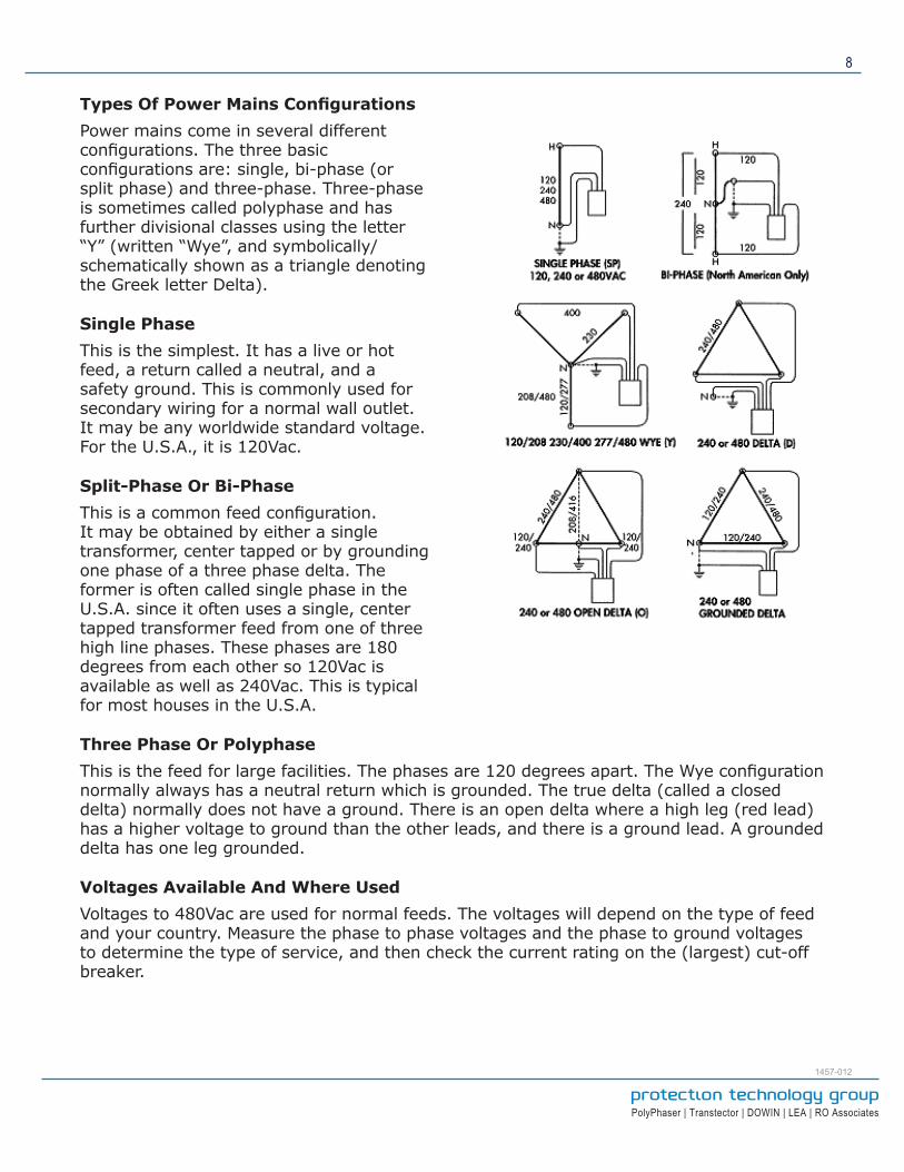
Types Of Power Mains ConfigurationsPower mains come in several different configurations. The three basic configurations are: single, bi-phase (or split phase) and three-phase. Three-phase is sometimes called polyphase and has further divisional classes using the letter “Y” (written “Wye”, and symbolically/schematically shown as a triangle denoting the Greek letter Delta).
Single PhaseThis is the simplest. It has a live or hot feed, a return called a neutral, and a safety ground. This is commonly used for secondary wiring for a normal wall outlet. It may be any worldwide standard voltage. For the U.S.A., it is 120Vac.
Split-Phase Or Bi-PhaseThis is a common feed configuration. It may be obtained by either a single transformer, center tapped or by grounding one phase of a three phase delta. The former is often called single phase in the U.S.A. since it often uses a single, center tapped transformer feed from one of three high line phases. These phases are 180 degrees from each other so 120Vac is available as well as 240Vac. This is typical for most houses in the U.S.A.
Three Phase Or PolyphaseThis is the feed for large facilities. The phases are 120 degrees apart. The Wye configuration normally always has a neutral return which is grounded. The true delta (called a closed delta) normally does not have a ground. There is an open delta where a high leg (red lead) has a higher voltage to ground than the other leads, and there is a ground lead. A grounded delta has one leg grounded.
Voltages Available And Where UsedVoltages to 480Vac are used for normal feeds. The voltages will depend on the type of feed and your country. Measure the phase to phase voltages and the phase to ground voltages to determine the type of service, and then check the current rating on the (largest) cut-off breaker.
Protection Technology Group Applications Guide 9
Connections For ProtectorsThe wire types and diameter (AWG) recommended connections for the ac mains protectors are given for each model and service type. Only the voltages change. The wires are properly color-coded for identification (i.e., Black for Hot (L1), White or Grey for Neutral, Red for additional Hot (L2), Blue for additional Hot (L3), Green, or Green with Yellow Stripe or bare copper wire for Ground).
Shunt Or In-Line And Where To Use EachIn-line (or “series”) protectors are load bearing; shunt types (or “parallel”) are not. In-lines are presently available up to 600A. These have redundancy, better surge limiting and provide filtering. Shunt types have no real load current limit, however, the larger the load, the larger the wires, and the more the surge energy will follow the conductors with the largest surface area. This means that more than one protector should be used. Two shunt protectors separated by twenty feet of wiring in steel conduit almost equal a single in-line protector. Both types have alarm contacts and field replaceable surge components.
We hope this terminology guide has been useful. Contact PolyPhaser at 1.800.882.9110 or 208.772.8515 for additional information.