Embed Size (px)
Citation preview
Page 1 of 14
Protection of Exposed, Unexpanded Plastic Containers Incorporating Cartoned, Unexpanded Plastic Commodity in a Volume Optimized,
Vertically Integrated Rack Storage Array
March 4, 2014
Daniel R. Steppan UL LLC
333 Pfingsten Road Northbrook, IL 60062
(847) 664-3574 [email protected]
Ivar Fjeldheim Product Manager Autostore
Jakob Hatteland Computer AS +47 5276 3542
Background of Racking System Investigated
AutoStore Small Parts Storage System
The automated small parts storage system, AutoStore, efficiently picks and stores single items and small cases to make better use of available space and increases efficiency at integrated goods-to-person workstations. The AutoStore automated small parts storage system quickly processes small parts orders and single-item picking. Robots collect the required bins and present them at integrated picking stations – increasing efficiency and maximizing space utilization.
Benefits:
Better use of available space Easy integration into existing buildings Modular design allows for scalability Energy-efficient design for optimized energy consumption Easy access and maintenance
Page 2 of 14
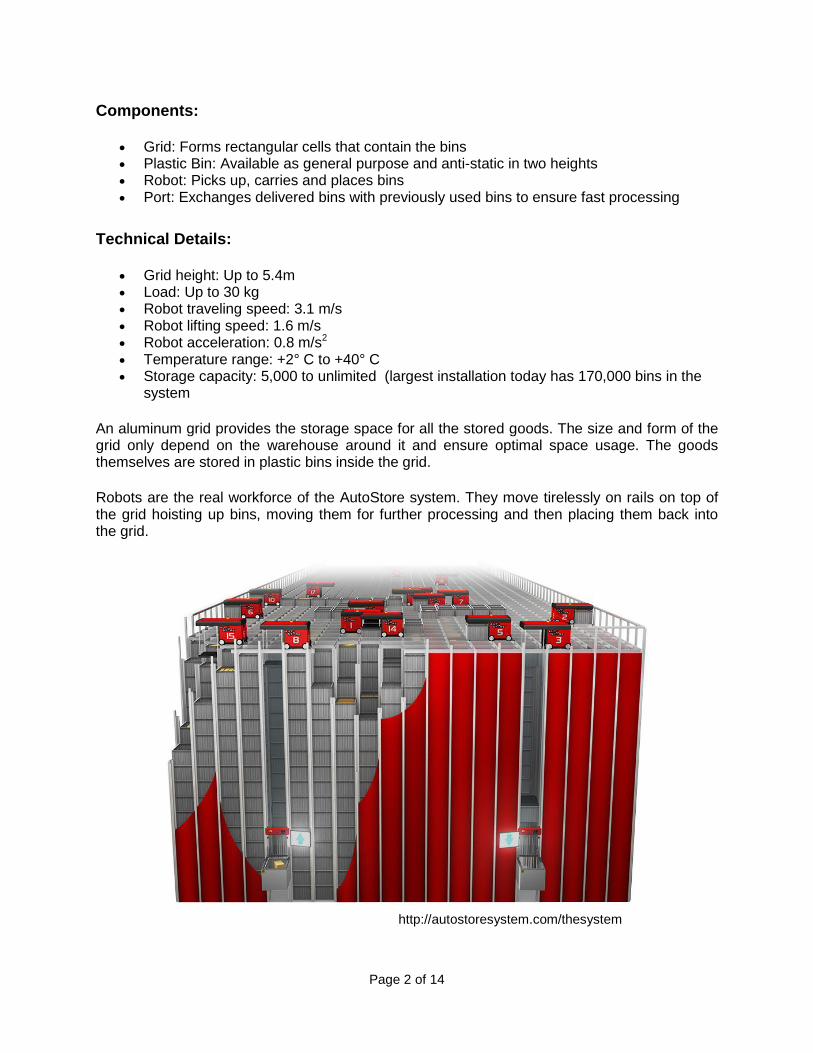
Components:
Grid: Forms rectangular cells that contain the bins Plastic Bin: Available as general purpose and anti-static in two heights Robot: Picks up, carries and places bins Port: Exchanges delivered bins with previously used bins to ensure fast processing
Technical Details:
Grid height: Up to 5.4m Load: Up to 30 kg Robot traveling speed: 3.1 m/s Robot lifting speed: 1.6 m/s Robot acceleration: 0.8 m/s2 Temperature range: +2° C to +40° C Storage capacity: 5,000 to unlimited (largest installation today has 170,000 bins in the
system
An aluminum grid provides the storage space for all the stored goods. The size and form of the grid only depend on the warehouse around it and ensure optimal space usage. The goods themselves are stored in plastic bins inside the grid.
Robots are the real workforce of the AutoStore system. They move tirelessly on rails on top of the grid hoisting up bins, moving them for further processing and then placing them back into the grid.
http://autostoresystem.com/thesystem
Page 3 of 14
Fire Safety Concerns
• People do not normally access the storage area of the AutoStore system. The probability for unintentional or intentional ignition caused by personnel is therefore low.
• The design of the robots fulfill the requirements of the electrical safety standard IEC 60950-1, so the probability for fire in a robot is expected to be low.
• Storage of flammable liquids is not allowed. • Storage of commodity containing large amount of expanded plastic material is
not likely. Design benefits from a sprinkler protection point of view:
• The storage is very compact with narrow flue spaces. Air movement through the array is therefore restricted and a slow fire growth rate was verified.
• The flue spaces are always regular and open. No bins or commodity will block the flues.
• The storage array is very stable. Collapse or leaning of stacks across flue spaces is not likely to occur during initial fire development.
• The vertical aluminum supports limit the possibilities for horizontal fire spread. Design disadvantages:
• The bins have solid bottoms that are not permeable to water. • No lids are used on the bins and water from sprinklers will initially be collected in
the topmost bins. • The flue spaces are narrow which will limit the amount of water from sprinklers
reaching the seat of a fire. • The robot’s grid track over the flue spaces limit the ability for the water from
sprinklers going directly down the flue spaces. Large Scale Fire Sprinkler Test Objectives:
• The development of an efficient sprinkler protection concept able to suppress a fire at an early stage, thereby:
- protecting the building, - limit fire spread, and, - limit the overall fire damage.
• To determine the most effective manual fire-fighting and post fire mitigation strategy.
Page 4 of 14
Large Scale Fire Testing Summary Test Parameters: Four fire tests were conducted to determine a density / area ceiling sprinkler system’s effectiveness on the fire control of burning high density polyethylene plastic bins and cartoned group A unexpanded plastic commodity in a tightly packed vertical racking configuration constructed from aluminum components. Nominal 17 ft. (5.2 m) storage of the commodity was investigated in a 35 ft. (10.7 m) tall space for a nominal 18 ft. (5.5 m) clearance in tests 1 and 2. Seventeen (17) ft. (5.2 m) nominal storage of the commodity was investigated in a 27 ft. (8.2 m) tall space for a nominal 10 ft. (3 m) clearance in tests 3 and 4. The commodity used in the investigation consisted of outer HDPE plastic bins measuring 17-3/8 inches (441 mm) wide by 25-3/8 inches (645 mm) long by 13 inches (330 mm) tall. Three corrugated cartons of unexpanded Group A plastic commodity was centrally positioned inside each outer plastic bin. Each of the corrugated cartons contained 12 crystal polystyrene cups. The corrugated cartons measured 7-7/8 inch (200 mm) wide by 11-1/2 inches (292 mm) long by 8-1/2 inches (216 mm) tall. In the test, a 7 wide by 10 long by 16 tall array of the aforementioned HDPE bins with cartoned Group A plastic commodity, were positioned within an aluminum racking array. The array provided for minimal air space laterally between the plastic bins, and no air space vertically, as the bins were stacked one on top of the other within the racking array. The total amount of plastic bins for Tests 1, 2 and 4 was 1,120. A limited group of bins (16 total) were removed for Test 3 in the vicinity of the ignition source, such that 1,104 bins were used in this test. The automatic sprinkler system incorporated the following features:
Nominal K=11.2 (gpm/psig1/2), 3/4 inch NPT upright sprinklers, positioned nominally 6-1/2 inches (165 mm) below the ceiling.
For tests 1 and 2, the operating sprinklers incorporated a flowing pressure of 28 psig (1.9 bar) for a nominal 0.60 gpm/ ft2 (24.4 mm/minute) applied discharge density.
For tests 3 and 4, the operating sprinklers incorporated a flowing pressure of 43 psig (3.0 bar) for a nominal 0.74 gpm/ ft2 (30.2 mm/minute) applied discharge density.
The sprinklers incorporated 155 °F (68°C) temperature rated, quick response heat responsive elements with 3 mm glass bulbs.
The sprinklers were installed on 10 ft. (3.05 m) branchline spacing with the sprinklers spaced 10 ft. (3.05 m) on center on each branchline.
Page 5 of 14
Test Results: The automatic sprinkler system that was employed for Tests 1, 3 and 4's configuration, controlled the fire with limited lateral fire spread within the test array. The automatic sprinkler system that was employed for Test 2's configuration did not control the fire's lateral fire spread within the test array. A summary of the test parameters and results in metric units are provided in Table 1.
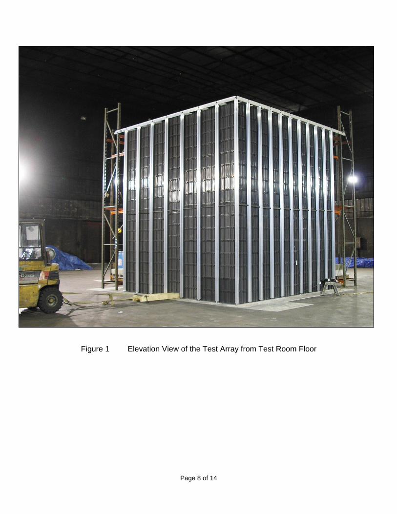
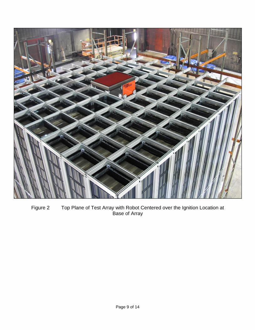
A summary of the test parameters and results in U.S. customary units are provided in Table 2. Figures 1 and 2 show the test arrangement for the project. Figures 3 through 6 show the plan view damage assessment for each test.
Page 6 of 14
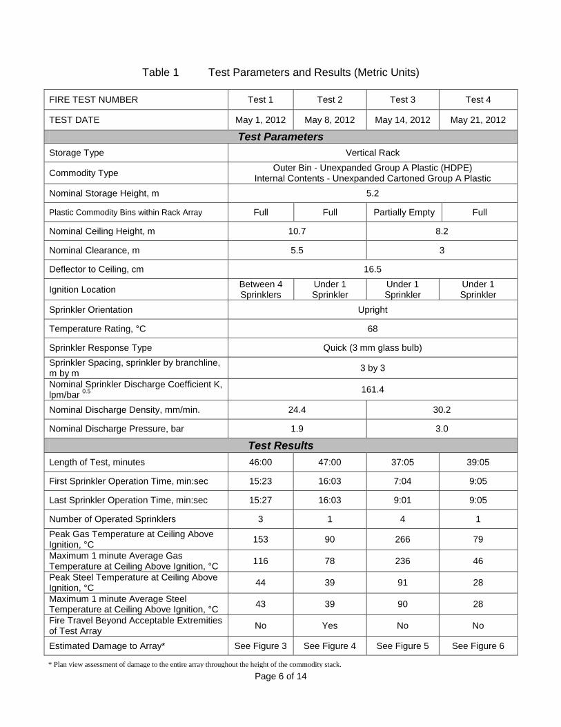
Table 1 Test Parameters and Results (Metric Units)
FIRE TEST NUMBER Test 1 Test 2 Test 3 Test 4
TEST DATE May 1, 2012 May 8, 2012 May 14, 2012 May 21, 2012
Test Parameters
Storage Type Vertical Rack
Commodity Type Outer Bin - Unexpanded Group A Plastic (HDPE)
Internal Contents - Unexpanded Cartoned Group A Plastic
Nominal Storage Height, m 5.2
Plastic Commodity Bins within Rack Array Full Full Partially Empty Full
Nominal Ceiling Height, m 10.7 8.2
Nominal Clearance, m 5.5 3
Deflector to Ceiling, cm 16.5
Ignition Location Between 4 Sprinklers
Under 1 Sprinkler
Under 1 Sprinkler
Under 1 Sprinkler
Sprinkler Orientation Upright
Temperature Rating, °C 68
Sprinkler Response Type Quick (3 mm glass bulb)
Sprinkler Spacing, sprinkler by branchline, m by m
3 by 3
Nominal Sprinkler Discharge Coefficient K, lpm/bar
0.5
161.4
Nominal Discharge Density, mm/min. 24.4 30.2
Nominal Discharge Pressure, bar 1.9 3.0
Test Results
Length of Test, minutes 46:00 47:00 37:05 39:05
First Sprinkler Operation Time, min:sec 15:23 16:03 7:04 9:05
Last Sprinkler Operation Time, min:sec 15:27 16:03 9:01 9:05
Number of Operated Sprinklers 3 1 4 1
Peak Gas Temperature at Ceiling Above Ignition, °C
153 90 266 79
Maximum 1 minute Average Gas Temperature at Ceiling Above Ignition, °C
116 78 236 46
Peak Steel Temperature at Ceiling Above Ignition, °C
44 39 91 28
Maximum 1 minute Average Steel Temperature at Ceiling Above Ignition, °C
43 39 90 28
Fire Travel Beyond Acceptable Extremities of Test Array
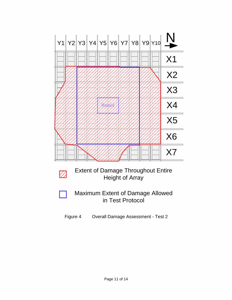
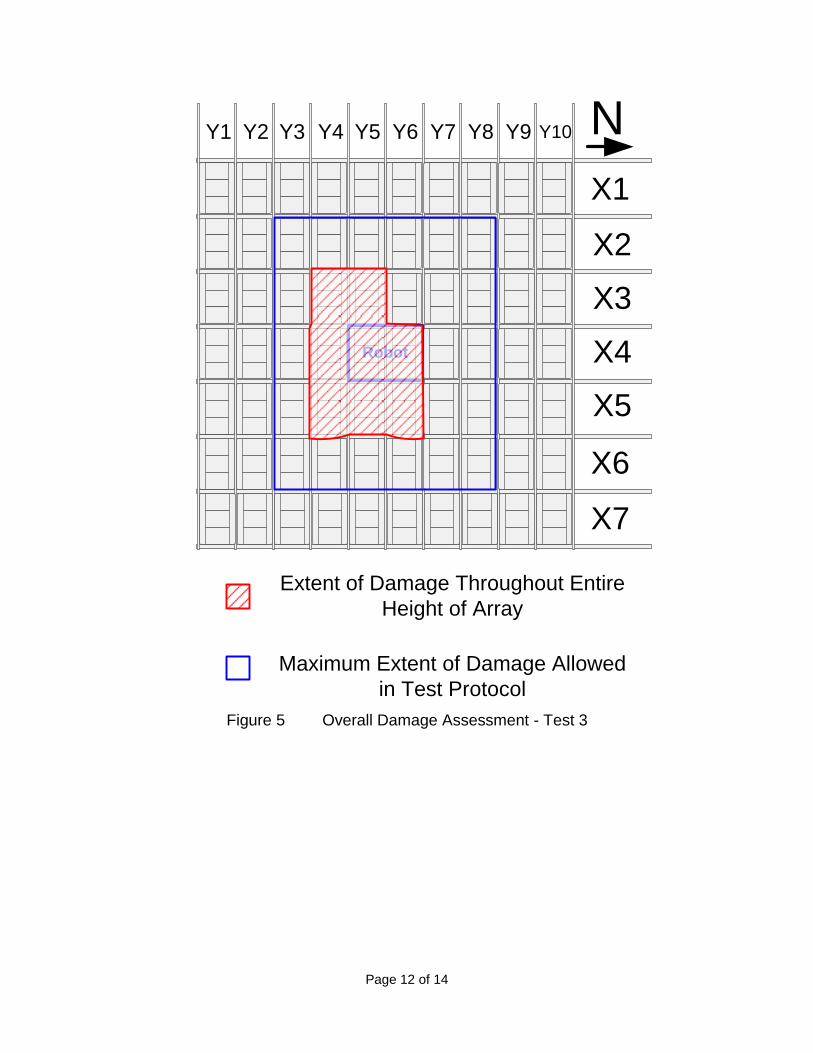
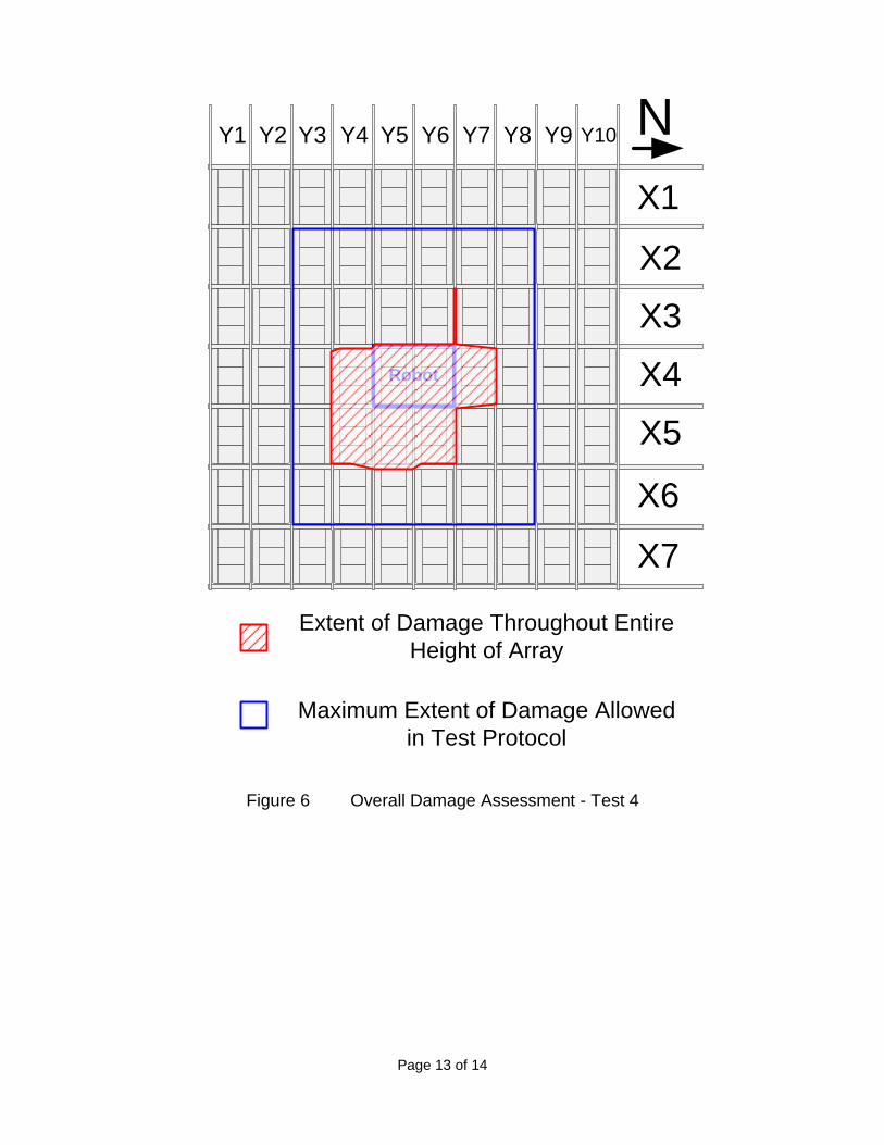
No Yes No No
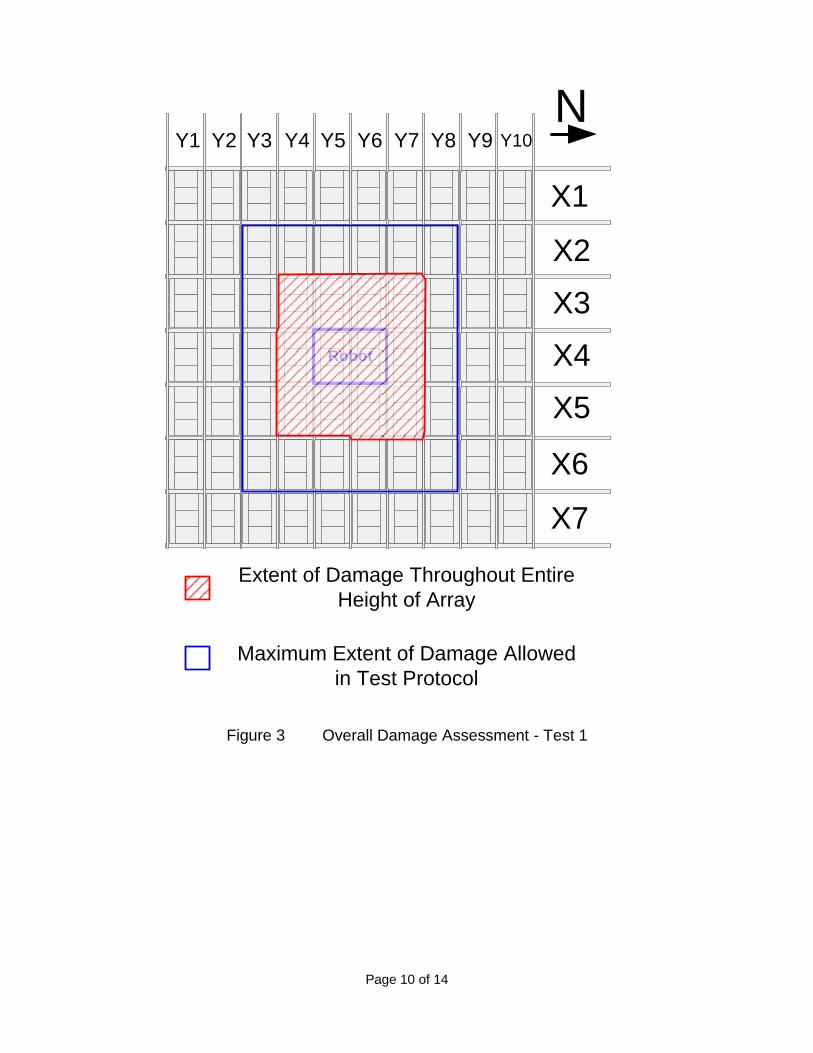
Estimated Damage to Array* See Figure 3 See Figure 4 See Figure 5 See Figure 6
* Plan view assessment of damage to the entire array throughout the height of the commodity stack.
Page 7 of 14
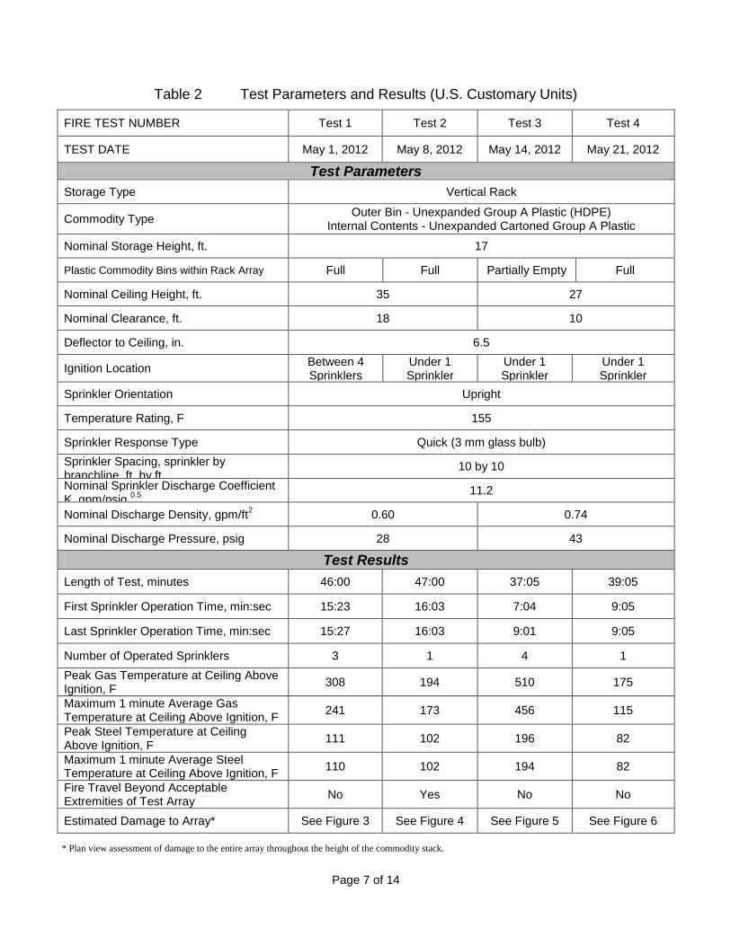
Table 2 Test Parameters and Results (U.S. Customary Units)
FIRE TEST NUMBER Test 1 Test 2 Test 3 Test 4
TEST DATE May 1, 2012 May 8, 2012 May 14, 2012 May 21, 2012
Test Parameters
Storage Type Vertical Rack
Commodity Type Outer Bin - Unexpanded Group A Plastic (HDPE)
Internal Contents - Unexpanded Cartoned Group A Plastic
Nominal Storage Height, ft. 17
Plastic Commodity Bins within Rack Array Full Full Partially Empty Full
Nominal Ceiling Height, ft. 35 27
Nominal Clearance, ft. 18 10
Deflector to Ceiling, in. 6.5
Ignition Location Between 4 Sprinklers
Under 1 Sprinkler
Under 1 Sprinkler
Under 1 Sprinkler
Sprinkler Orientation Upright
Temperature Rating, F 155
Sprinkler Response Type Quick (3 mm glass bulb)
Sprinkler Spacing, sprinkler by branchline, ft. by ft.
10 by 10
Nominal Sprinkler Discharge Coefficient K, gpm/psig
0.5
11.2
Nominal Discharge Density, gpm/ft2 0.60 0.74
Nominal Discharge Pressure, psig 28 43
Test Results
Length of Test, minutes 46:00 47:00 37:05 39:05
First Sprinkler Operation Time, min:sec 15:23 16:03 7:04 9:05
Last Sprinkler Operation Time, min:sec 15:27 16:03 9:01 9:05
Number of Operated Sprinklers 3 1 4 1
Peak Gas Temperature at Ceiling Above Ignition, F
308 194 510 175
Maximum 1 minute Average Gas Temperature at Ceiling Above Ignition, F
241 173 456 115
Peak Steel Temperature at Ceiling Above Ignition, F
111 102 196 82
Maximum 1 minute Average Steel Temperature at Ceiling Above Ignition, F
110 102 194 82
Fire Travel Beyond Acceptable Extremities of Test Array
No Yes No No
Estimated Damage to Array* See Figure 3 See Figure 4 See Figure 5 See Figure 6
* Plan view assessment of damage to the entire array throughout the height of the commodity stack.
Page 8 of 14
Figure 1 Elevation View of the Test Array from Test Room Floor
Page 9 of 14
Figure 2 Top Plane of Test Array with Robot Centered over the Ignition Location at Base of Array
Page 10 of 14
Figure 3 Overall Damage Assessment - Test 1
Robot
Y1 Y2
X1
Y3 Y4 Y5 Y6 Y7 Y8 Y9 Y10
X2
X3
X4
X5
X6
X7
Extent of Damage Throughout Entire
Height of Array
Maximum Extent of Damage Allowed
in Test Protocol
N
Page 11 of 14
Figure 4 Overall Damage Assessment - Test 2
Robot
Y1 Y2
X1
Y3 Y4 Y5 Y6 Y7 Y8 Y9 Y10
X2
X3
X4
X5
X6
X7
Extent of Damage Throughout Entire
Height of Array
Maximum Extent of Damage Allowed
in Test Protocol
N
Page 12 of 14
Figure 5 Overall Damage Assessment - Test 3
Robot
Y1 Y2
X1
Y3 Y4 Y5 Y6 Y7 Y8 Y9 Y10
X2
X3
X4
X5
X6
X7
Extent of Damage Throughout Entire
Height of Array
Maximum Extent of Damage Allowed
in Test Protocol
N
Page 13 of 14
Figure 6 Overall Damage Assessment - Test 4
Robot
Y1 Y2
X1
Y3 Y4 Y5 Y6 Y7 Y8 Y9 Y10
X2
X3
X4
X5
X6
X7
Extent of Damage Throughout Entire
Height of Array
Maximum Extent of Damage Allowed
in Test Protocol
N
Page 14 of 14
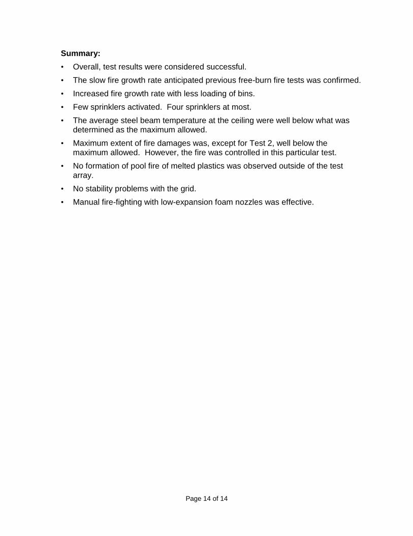
Summary:
• Overall, test results were considered successful.
• The slow fire growth rate anticipated previous free-burn fire tests was confirmed.
• Increased fire growth rate with less loading of bins.
• Few sprinklers activated. Four sprinklers at most.
• The average steel beam temperature at the ceiling were well below what was determined as the maximum allowed.
• Maximum extent of fire damages was, except for Test 2, well below the maximum allowed. However, the fire was controlled in this particular test.
• No formation of pool fire of melted plastics was observed outside of the test array.
• No stability problems with the grid.
• Manual fire-fighting with low-expansion foam nozzles was effective.