Embed Size (px)
Citation preview

Protecting Drinking Water Pipelines with Inflow Prevention
VAL-MATIC VALVE AND MANUFACTURING CORP. 905 RIVERSIDE DRIVE, ELMHURST, IL 60126 TEL. (630) 941-7600 FAX. (630) 941-8042 www.valmatic.com Copyright © 2017 Val-Matic Valve and Manufacturing Corp.

i
FOREWORD Protecting Drinking Water Pipelines with Inflow Prevention was written to assist water distribution system design engineers in reducing the risk to public health from contaminated drinking water by understanding the use of inflow preventer assemblies in water distribution systems. This paper is not intended to provide all of the information necessary for specifying these devices, but rather to explain their function and performance criteria along with common engineering parameters associated with the application of air valves and cross connection control devices. Successful system design should consider the functions of the air valves and vents together with the need to protect the system from contamination and loss of efficiency.
With this knowledge, the design engineer can better apply American Water Works Standard C514 and American Society of Sanitary Engineering (ASSE) Standard 1063 Inflow Preventers and understand the application, sizing, installation guidelines and code applications that affect their use. The rating information provided is based on generally accepted products and standards, which offer valuable information for predicting performance.
Val-Matic offers no warranty or representation as to the design information and methodologies in this paper. Use of this paper should be made under the direction of trained engineers exercising independent judgment regarding the suggested use and application of valves and related devices in fluid systems.
1
PROTECTING DRINKING WATER PIPELINES WITH INFLOW PREVENTION
INTRODUCTION
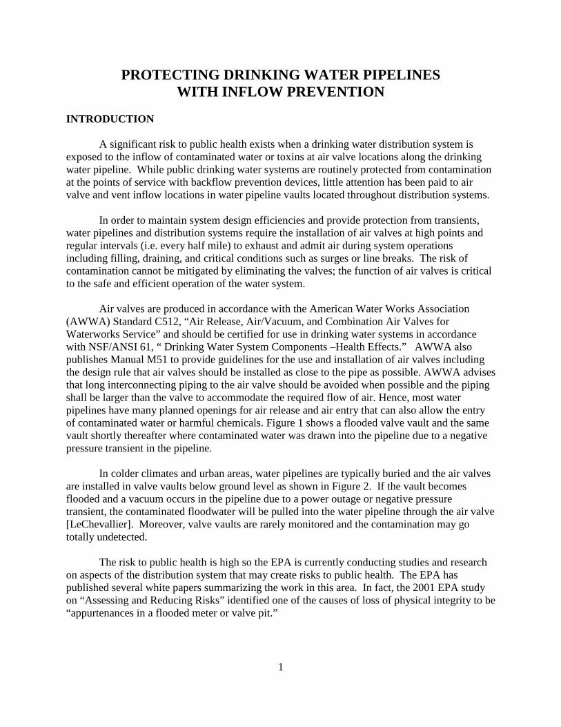
A significant risk to public health exists when a drinking water distribution system is exposed to the inflow of contaminated water or toxins at air valve locations along the drinking water pipeline. While public drinking water systems are routinely protected from contamination at the points of service with backflow prevention devices, little attention has been paid to air valve and vent inflow locations in water pipeline vaults located throughout distribution systems.
In order to maintain system design efficiencies and provide protection from transients, water pipelines and distribution systems require the installation of air valves at high points and regular intervals (i.e. every half mile) to exhaust and admit air during system operations including filling, draining, and critical conditions such as surges or line breaks. The risk of contamination cannot be mitigated by eliminating the valves; the function of air valves is critical to the safe and efficient operation of the water system.
Air valves are produced in accordance with the American Water Works Association
(AWWA) Standard C512, “Air Release, Air/Vacuum, and Combination Air Valves for Waterworks Service” and should be certified for use in drinking water systems in accordance with NSF/ANSI 61, “ Drinking Water System Components –Health Effects.” AWWA also publishes Manual M51 to provide guidelines for the use and installation of air valves including the design rule that air valves should be installed as close to the pipe as possible. AWWA advises that long interconnecting piping to the air valve should be avoided when possible and the piping shall be larger than the valve to accommodate the required flow of air. Hence, most water pipelines have many planned openings for air release and air entry that can also allow the entry of contaminated water or harmful chemicals. Figure 1 shows a flooded valve vault and the same vault shortly thereafter where contaminated water was drawn into the pipeline due to a negative pressure transient in the pipeline.
In colder climates and urban areas, water pipelines are typically buried and the air valves are installed in valve vaults below ground level as shown in Figure 2. If the vault becomes flooded and a vacuum occurs in the pipeline due to a power outage or negative pressure transient, the contaminated floodwater will be pulled into the water pipeline through the air valve [LeChevallier]. Moreover, valve vaults are rarely monitored and the contamination may go totally undetected. The risk to public health is high so the EPA is currently conducting studies and research on aspects of the distribution system that may create risks to public health. The EPA has published several white papers summarizing the work in this area. In fact, the 2001 EPA study on “Assessing and Reducing Risks” identified one of the causes of loss of physical integrity to be “appurtenances in a flooded meter or valve pit.”

2
Figure 1. Submerged Air Valve Vault [LeChevallier]
Figure 2. Typical Air Valve Vault Design

3
Until such time as federal guidelines are published, some waterworks regulations require the outlet of the air valve to be connected to a vent pipe that extends above grade and above the expected flood level [Great Lakes, 8.5.2], see Figure 3. Unfortunately, this type of vent pipe subjects the air valve and pipeline to freezing temperatures and external malicious tampering. Vent pipes inadvertently provide a vulnerable direct connection between public areas and the buried potable water line setting up a potential threat. A hazardous substance or toxin can be intentionally introduced into the vent pipe and when the air valve admits air, the contaminant will be drawn directly into the water pipeline. Given recent requirements from Homeland Security, potential threats such as these must be identified and mitigated. Finally, many water pipelines run under streets or in dense urban areas where such risers cannot be conveniently located adjacent to the pipeline.
Figure 3. Vent Pipe Connected to the Air Valve HISTORY OF THE INFLOW PREVENTER
As a prominent supplier of air valves for the water industry, Val-Matic Valve & Mfg. Corp. was asked by various utilities and consulting engineers to offer a solution that would avoid the use of air valve vent pipes, enhance the security of drinking water systems, and properly protect the system from contaminated flood water and malicious sabotage. In collaboration with some water utilities and water system engineering consultants, Val-Matic developed the Inflow Preventer in 1997. An Inflow Preventer as shown in Figure 4 is a mechanical device mounted on

4
the outlet of an air valve or vent pipe to allow normal flow of air in and out of the water system and prevent inflow of contaminated water into a water system as a result of flooding or malicious tampering. When flood water enters the bottom of the device, it raises the floats, which in turn, seal tightly against sensitive resilient seats with integral O-ring type sealing surfaces. The device has redundant sealing chambers for added reliability. Even with the vault flooded and the device closed, the air valve and device can still release air from the pipeline to maintain pipeline efficiency. However, when a vacuum occurs in the pipeline flood water will not be allowed to enter the pipeline so the vacuum protection feature of the air valve will be temporarily lost. If vacuum protection is critical to the structural integrity of the pipe, then an alternate scheme such as a closed surge tank should be considered.
FIGURE 4. Typical ASSE 1063 Inflow Preventer Installation
Val-Matic worked with the American Society of Sanitary Engineering (ASSE) and
requested that they develop a product standard for inflow preventers since ASSE publishes standards on many cross-connection devices. ASSE initiated the ANSI Product Identification Notification System (PINS) process and was granted the right to develop a consensus standard for the Inflow Preventer. An ASSE 1063 Working group was established in 2005 and a standard was promulgated in accordance with procedures developed by the American National Standards Institute (ANSI), ASSE Standard #1063-2008, “Air Valve and Vent Inflow Preventer.” The ASSE Cross Connection Committee later reviewed and added the assembly to their Series 5000 Qualification Program and the field test instruction are now published in the 2015 edition of this Standard. This will enable certified maintenance and test personnel around the country to be trained and certified by ASSE to test these devices.
In 2012, the American Water Works Association (AWWA) formed a subcommittee to write a congruent standard AWWA/ANSI C514, “Air Valve and Vent Inflow Preventer Assemblies for Potable Water Distribution Systems and Storage Facilities.” The standard was published in 2015 for the water distribution industry. The Inflow Preventer was also added to

5
American Water Works Association, AWWA M51, “Manual of Water Supply Practices, Air-Release, Air/Vacuum, and Combination Air Valves,” in 2016 as a possible solution for flooded air valve vaults.
During the development of these standards, production devices underwent an extensive
testing program at a third-party independent test laboratory, Wyle Laboratories in Huntsville, Alabama. Wyle conducted tests in accordance with the ASSE standard to verify the performance test methodologies. Val-Matic submitted the test reports to ASSE and applied for and received ASSE Certification for the FloodSafe Inflow Preventer. In subsequent years, Val-Matic has provided hundreds of these devices in many water districts in the USA and Canada.
APPLICABLE REQUIREMENTS
ASSE Standard #1063-2008 provides the product requirements for Inflow Preventers
including: a) The purpose of the assembly is to exhaust and admit air but prevent the entry of contaminated water when the outlet of the air valve becomes submerged or is the target of malicious tampering. b) The assembly shall have an outlet basket, redundant check devices, and the ability to be field tested. c) The assembly shall be installed as prescribed and periodically tested, at least annually.
The California Department of Public Health (DHS) publishes requirements to protect air valves from flooding in Section 64576 of the Revised Waterworks Standards, “Each new air-release, air vacuum, or combination valve, and any such valve installed to replace an existing valve shall be installed such that its vent opening is above grade, above the calculated 100-year flood water level, and, if recorded data are available, above the highest recorded water level.” In 2008, Foster City, California filed a permit to install new air valves on their three-mile long, 24-inch diameter drinking water supply pipeline and included the use of inflow preventers because the pipeline and air valve vaults were beneath city streets thereby preventing the installation of air valve riser pipes, see Figure 5.

6
FIGURE 5. Water Pipeline in Foster City, CA
The DHS approved the permit provided that the city conduct regular inspections and testing of the inflow preventers by certified technicians. In the permit dated December 10, 2008, the DHS stated that, “The California Department of Public Health has evaluated the application and the supporting material and has determined that the alternate design and monitoring program proposed by the water system comply with Section 64576 of the California Waterworks Standards for Capital Improvement Project No. 760 will provide at least the same level of protection to public health.” Since the installation, the City has conducted regular inspections and testing in all seven locations along the pipeline. A typical installation is shown in Figure 6 with the vault cover removed exposing the air valve equipment. The successful Inflow Preventer installation in Foster City, California demonstrates the benefits of the device in municipal water systems. The Inflow Preventer solves a defined problem by protecting the city drinking water system from contamination by flood water and malicious tampering.
Location of Air Valve Vault

7
Figure 6. Air Valve Vault, Foster City, CA According to AWWA M51 practices, a valve vault can be equipped with an inflow preventer per AWWA C514 to prevent contamination from flooding as shown in Figure 7. The vent pipe provides for regular airflow but is equipped with dampers to prevent the convection of cold air. When required by the water system, the dampers open fully to allow airflow in both directions. If the vault is subject to flooding, then inflow preventer can be installed on the valve outlet as shown. The inflow preventer is normally open and allows normal air flow in and out of the water system and prevents the inflow of contaminated water into a drinking water system as a result of flooding. PRODUCT APPLICATION AND PERFORMANCE Inflow preventers are available in nominal sizes 1 inch to 4 inch threaded connections and 6 inch to 12 inch flanged connections with a maximum working pressure of 25 psig. The pressure rating of the device does not need to equal the pipeline rating because the device is “normally open” and cannot be pressurized by the pipeline. The only pressure that the device is subjected to is that pressure from the floodwater elevation which should not exceed 50 feet (25 psig). The size of the inflow preventer is selected to match the nominal size of the air valve or based on flow rates if that data is available.
3 inch Inflow Preventer

8
Figure 7. Suggested AWWA Design for Vaults Subject to Flooding. The inflow preventer is piped to the outlet of the air valve or system vent pipe in the vertical position and will admit and vent air out its screened bottom. The device can be mounted adjacent to the air valve or several feet away on the side of the vault. The device is available with a side bracket for wall mounting on larger vaults as shown in Figure 7. The connecting pipe shall be of a diameter equal to the nominal size of the assembly. The piping is installed horizontal or sloping downward toward the device so that water does not collect in the piping. A clearance of 12 inch is required on the sides and bottom of the device to allow for proper operation and testing.
The installed inflow preventer should be initially tested by a certified tester and periodically tested thereafter as recommended by the local authority having jurisdiction but at least annually. According to the ASSE standard, the inflow preventer must seal drop tight with submergences as low as 12 in. water column. The device is equipped with test cocks for regular field testing in accordance with ASSE 5000 and as shown in Figure 8. Testing consists of

9
removing the bottom screen, installing a test plug in the bottom of the unit, and applying a 12 in. water column to each chamber independently to verify that there is no leakage. See an on-line video for a demonstration of the testing protocol, YouTube: Making Your System Safe with the Val-Matic FloodSafe.”
Figure 8. Inflow Preventer Field Test Diagram.
CONCLUSION Given the heightened demand for security and safe drinking water, inflow prevention is important because air valves and reservoir vents are vulnerable to flood contamination as well as malicious tampering. The use of vent pipes can worsen the problem by allowing cold air to enter the air valve and potentially make it inoperable due to freezing and directly exposing the pipeline to the outside and malicious tampering. AWWA C514 Inflow preventers can be applied to new or existing air valves and reservoir vents to substantially mitigate these threats. REFERENCES
1. American Society of Sanitary Engineering, ASSE 1063, “Air Valve and Vent Inflow
Preventer,” 2008. 2. American Society of Sanitary Engineering, ASSE 5000, “Cross Connection Control
Professional Qualifications Standard”, 2015. 3. American Water Works Association, AWWA C512, “Air-Release, Air/Vacuum, and

10
Combination Air Valves for Waterworks Service,” 2015. 4. American Water Works Association, AWWA M51, “Manual of Water Supply Practices,
Air-Release, Air/Vacuum, and Combination Air Valves,” Second Edition, 2016. 5. American Water Works Association, AWWA C514, “Air Valve and Vent Inflow
Preventer Assemblies for Potable Water Distribution System and Storage Facilities,” 2015.
6. EPA, “Potential Contamination due to Cross-Connections and Backflow and the
Associated Health Risks,” September 27, 2001. 7. Great Lakes – Upper Mississippi River Board of State and Provincial Public Health and
Environmental Managers, Recommended Standards for Water Works, 2012 Edition. 8. LeChevallier, Mark W., et. Al., “The Potential for Health Risks form Intrusion of
Contaminants Into the Distribution System From Pressure Transients.” Journal of Water and Health, Volume 01.1, 2003.
9. National Research Council, “Drinking Water Distribution Systems: Assessing and
Reducing Risks,” The National Academies Press, 2006.