Embed Size (px)
Citation preview
BLACK BOX®
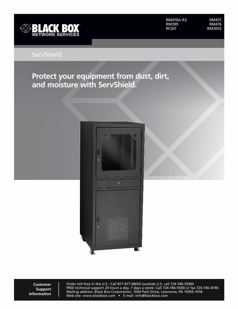
Protect your equipment from dust, dirt, and moisture with ServShield.
ServShield
Order toll-free in the U.S.: Call 877-877-BBOX (outside U.S. call 724-746-5500)FREE technical support 24 hours a day, 7 days a week: Call 724-746-5500 or fax 724-746-0746Mailing address: Black Box Corporation, 1000 Park Drive, Lawrence, PA 15055-1018Web site: www.blackbox.com • E-mail: [email protected]
Customer Support
Information
RM470A-R3 RM475 RM399 RM476 RF207 RM3055
724-746-5500 | blackbox.com Page 2
Trademarks Used in this Manual
Trademarks Used in this Manual
Black Box and the Double Diamond logo are registered trademarks of BB Technologies, Inc.
PLEXIGLAS is a registered trademark of Rohm & Haas Company.
UL is a registered trademark of Underwriters Laboratories, Inc.
Any other trademarks mentioned in this manual are acknowledged to be the property of the trademark owners.
We‘re here to help! If you have any questions about your application or our products, contact Black Box Tech Support at 724-746-5500
or go to blackbox.com and click on “Talk to Black Box.”You’ll be live with one of our technical experts in less than 30 seconds.
724-746-5500 | blackbox.com Page 3
FCC and RFI Statements
Federal Communications Commission and Industry Canada Radio Frequency Interference Statements
This equipment generates, uses, and can radiate radio-frequency energy, and if not installed and used properly, that is, in strict accordance with the manufacturer’s instructions, may cause inter ference to radio communication. It has been tested and found to comply with the limits for a Class A computing device in accordance with the specifications in Subpart B of Part 15 of FCC rules, which are designed to provide reasonable protection against such interference when the equipment is operated in a commercial environment. Operation of this equipment in a residential area is likely to cause interference, in which case the user at his own expense will be required to take whatever measures may be necessary to correct the interference.
Changes or modifications not expressly approved by the party responsible for compliance could void the user’s authority to operate the equipment.
This digital apparatus does not exceed the Class A limits for radio noise emis sion from digital apparatus set out in the Radio Interference Regulation of Industry Canada.
Le présent appareil numérique n’émet pas de bruits radioélectriques dépassant les limites applicables aux appareils numériques de la classe A prescrites dans le Règlement sur le brouillage radioélectrique publié par Industrie Canada.
724-746-5500 | blackbox.com Page 4
NOM Statement
Instrucciones de Seguridad(Normas Oficiales Mexicanas Electrical Safety Statement)1. Todas las instrucciones de seguridad y operación deberán ser leídas antes de que el aparato eléctrico sea operado.
2. Las instrucciones de seguridad y operación deberán ser guardadas para referencia futura.
3. Todas las advertencias en el aparato eléctrico y en sus instrucciones de operación deben ser respetadas.
4. Todas las instrucciones de operación y uso deben ser seguidas.
5. El aparato eléctrico no deberá ser usado cerca del agua—por ejemplo, cerca de la tina de baño, lavabo, sótano mojado o cerca de una alberca, etc.
6. El aparato eléctrico debe ser usado únicamente con carritos o pedestales que sean recomendados por el fabricante.
7. El aparato eléctrico debe ser montado a la pared o al techo sólo como sea recomendado por el fabricante.
8. Servicio—El usuario no debe intentar dar servicio al equipo eléctrico más allá a lo descrito en las instrucciones de operación. Todo otro servicio deberá ser referido a personal de servicio calificado.
9. El aparato eléctrico debe ser situado de tal manera que su posición no interfiera su uso. La colocación del aparato eléctrico sobre una cama, sofá, alfombra o superficie similar puede bloquea la ventilación, no se debe colocar en libreros o gabinetes que impidan el flujo de aire por los orificios de ventilación.
10. El equipo eléctrico deber ser situado fuera del alcance de fuentes de calor como radiadores, registros de calor, estufas u otros aparatos (incluyendo amplificadores) que producen calor.
11. El aparato eléctrico deberá ser connectado a una fuente de poder sólo del tipo descrito en el instructivo de operación, o como se indique en el aparato.
12. Precaución debe ser tomada de tal manera que la tierra fisica y la polarización del equipo no sea eliminada.
13. Los cables de la fuente de poder deben ser guiados de tal manera que no sean pisados ni pellizcados por objetos colocados sobre o contra ellos, poniendo particular atención a los contactos y receptáculos donde salen del aparato.
14. El equipo eléctrico debe ser limpiado únicamente de acuerdo a las recomendaciones del fabricante.
15. En caso de existir, una antena externa deberá ser localizada lejos de las lineas de energia.
16. El cable de corriente deberá ser desconectado del cuando el equipo no sea usado por un largo periodo de tiempo.
17. Cuidado debe ser tomado de tal manera que objectos liquidos no sean derramados sobre la cubierta u orificios de ventilación.
18. Servicio por personal calificado deberá ser provisto cuando: A: El cable de poder o el contacto ha sido dañado; u B: Objectos han caído o líquido ha sido derramado dentro del aparato; o C: El aparato ha sido expuesto a la lluvia; o D: El aparato parece no operar normalmente o muestra un cambio en su desempeño; o E: El aparato ha sido tirado o su cubierta ha sido dañada.
724-746-5500 | blackbox.com Page 5
Table of Contents
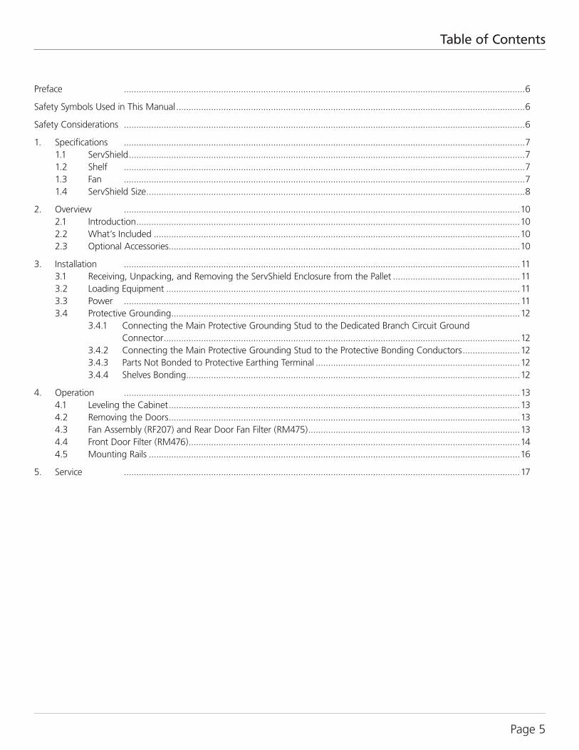
Preface .................................................................................................................................................................6
Safety Symbols Used in This Manual ............................................................................................................................................6
Safety Considerations .................................................................................................................................................................6
1. Specifications .................................................................................................................................................................7 1.1 ServShield ...............................................................................................................................................................7 1.2 Shelf .................................................................................................................................................................7 1.3 Fan .................................................................................................................................................................7 1.4 ServShield Size ........................................................................................................................................................8
2. Overview ...............................................................................................................................................................10 2.1 Introduction ..........................................................................................................................................................10 2.2 What’s Included ...................................................................................................................................................10 2.3 Optional Accessories .............................................................................................................................................10
3. Installation ...............................................................................................................................................................11 3.1 Receiving, Unpacking, and Removing the ServShield Enclosure from the Pallet ...................................................11 3.2 Loading Equipment ..............................................................................................................................................11 3.3 Power ...............................................................................................................................................................11 3.4 Protective Grounding ............................................................................................................................................12 3.4.1 Connecting the Main Protective Grounding Stud to the Dedicated Branch Circuit Ground Connector ...............................................................................................................................................12 3.4.2 Connecting the Main Protective Grounding Stud to the Protective Bonding Conductors .......................12 3.4.3 Parts Not Bonded to Protective Earthing Terminal ..................................................................................12 3.4.4 Shelves Bonding ......................................................................................................................................12
4. Operation ...............................................................................................................................................................13 4.1 Leveling the Cabinet .............................................................................................................................................13 4.2 Removing the Doors .............................................................................................................................................13 4.3 Fan Assembly (RF207) and Rear Door Fan Filter (RM475) .....................................................................................13 4.4 Front Door Filter (RM476) .....................................................................................................................................14 4.5 Mounting Rails .....................................................................................................................................................16
5. Service ...............................................................................................................................................................17
724-746-5500 | blackbox.com Page 6
Preface/Safety Symbols Used in This Manual
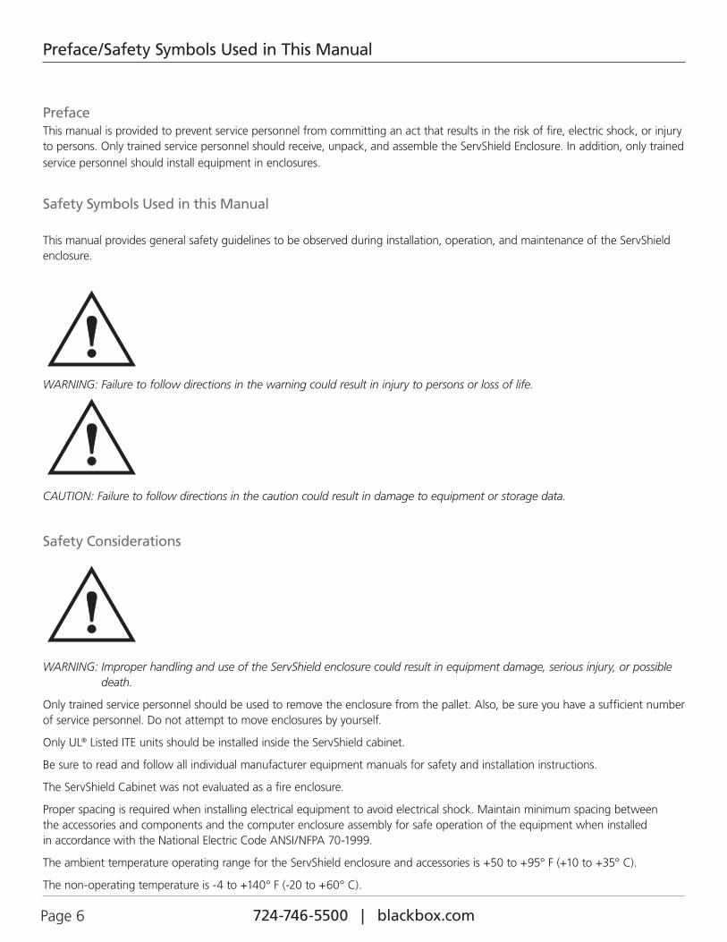
PrefaceThis manual is provided to prevent service personnel from committing an act that results in the risk of fire, electric shock, or injury to persons. Only trained service personnel should receive, unpack, and assemble the ServShield Enclosure. In addition, only trained service personnel should install equipment in enclosures.
Safety Symbols Used in this Manual
This manual provides general safety guidelines to be observed during installation, operation, and maintenance of the ServShield enclosure.
WARNING: Failure to follow directions in the warning could result in injury to persons or loss of life.
CAUTION: Failure to follow directions in the caution could result in damage to equipment or storage data.
Safety Considerations
WARNING: Improper handling and use of the ServShield enclosure could result in equipment damage, serious injury, or possible death.
Only trained service personnel should be used to remove the enclosure from the pallet. Also, be sure you have a sufficient number of service personnel. Do not attempt to move enclosures by yourself.
Only UL® Listed ITE units should be installed inside the ServShield cabinet.
Be sure to read and follow all individual manufacturer equipment manuals for safety and installation instructions.
The ServShield Cabinet was not evaluated as a fire enclosure.
Proper spacing is required when installing electrical equipment to avoid electrical shock. Maintain minimum spacing between the accessories and components and the computer enclosure assembly for safe operation of the equipment when installed in accordance with the National Electric Code ANSI/NFPA 70-1999.
The ambient temperature operating range for the ServShield enclosure and accessories is +50 to +95° F (+10 to +35° C).
The non-operating temperature is -4 to +140° F (-20 to +60° C).
724-746-5500 | blackbox.com Page 7
Chapter 1: Specifications
1. Specifications
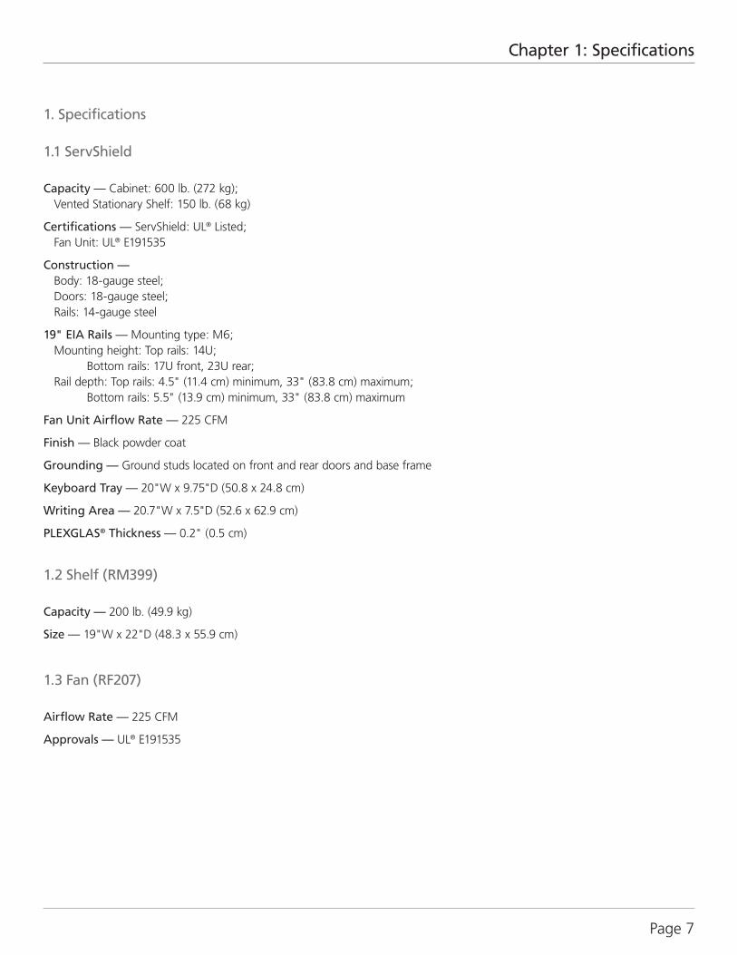
1.1 ServShield
Capacity — Cabinet: 600 lb. (272 kg); Vented Stationary Shelf: 150 lb. (68 kg)
Certifications — ServShield: UL® Listed; Fan Unit: UL® E191535
Construction — Body: 18-gauge steel; Doors: 18-gauge steel; Rails: 14-gauge steel
19" EIA Rails — Mounting type: M6; Mounting height: Top rails: 14U; Bottom rails: 17U front, 23U rear; Rail depth: Top rails: 4.5" (11.4 cm) minimum, 33" (83.8 cm) maximum; Bottom rails: 5.5" (13.9 cm) minimum, 33" (83.8 cm) maximum
Fan Unit Airflow Rate — 225 CFM
Finish — Black powder coat
Grounding — Ground studs located on front and rear doors and base frame
Keyboard Tray — 20"W x 9.75"D (50.8 x 24.8 cm)
Writing Area — 20.7"W x 7.5"D (52.6 x 62.9 cm)
PLEXGLAS® Thickness — 0.2" (0.5 cm)
1.2 Shelf (RM399)
Capacity — 200 lb. (49.9 kg)
Size — 19"W x 22"D (48.3 x 55.9 cm)
1.3 Fan (RF207)
Airflow Rate — 225 CFM
Approvals — UL® E191535
724-746-5500 | blackbox.com Page 8
Chapter 1: Specifications
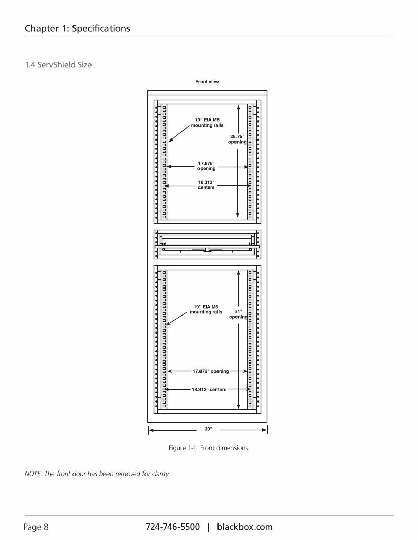
1.4 ServShield Size
19" EIA M6 mounting rails
30"
Front view
17.876" opening
18.312" centers
31" opening
25.75" opening
17.876" opening
18.312" centers
19" EIA M6 mounting rails
Figure 1-1. Front dimensions.
NOTE: The front door has been removed for clarity.
724-746-5500 | blackbox.com Page 9
Chapter 1: Specifications
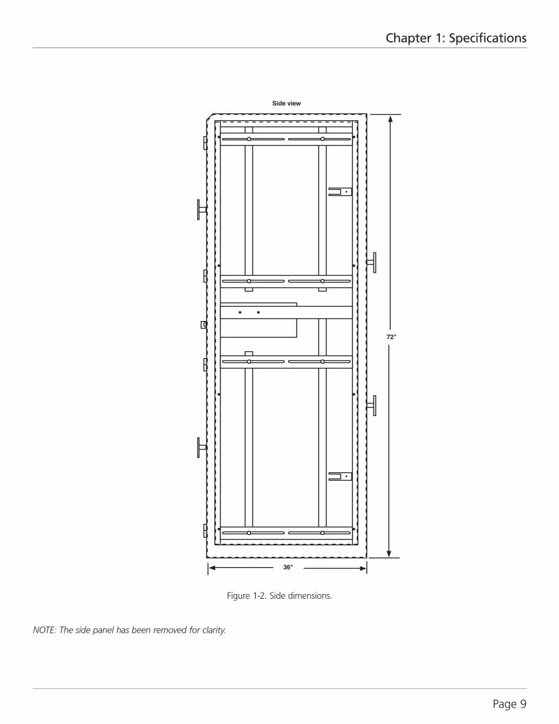
36"
72"
Side view
Figure 1-2. Side dimensions.
NOTE: The side panel has been removed for clarity.
724-746-5500 | blackbox.com Page 10
Chapter 2: Overview
2. Overview
2.1 IntroductionServShield protects your computer hardware in manufacturing environments and other industrial areas subject to harsh conditions.
The cabinet is constructed of steel and it holds 600 pounds (272 kg) of equipment. The cabinet is preassembled, so it’s easy to set up and use. Cabinet components include: upper, clear PLEXIGLAS® door; isolated, steel middle keyboard drawer; steel, perforated lower front door with dust filter; steel rear door furnished with fan assembly and dust filters; a gland plate (12"L x 2.5"W [30.5 x 6.4 cm]), which provides cable access on the bottom of the enclosure; one vented stationary shelf for mounting a monitor (200-lb. [90.8-kg] weight capacity); rubber casters; and leveling glides. All doors have compression latches and locks. Cabinet dimensions are 72"H x 30"W x 36"D (182.9 x 76.2 x 91.4 cm).
The top Plexiglas door, middle keyboard door, bottom front door, and rear door are keyed the same.
2.2 What’s Included• ServShield unit (assembled) with casters and leveling legs
• (4) sets of keys
• (30) M6 cage nuts
• (30) M6 screws
• This user’s manual
2.3 Optional AccessoriesYou may also need the following:
• 19" (48.3 cm) Sliding, Adjustable Tower Shelf (RM471)—at 19" (48.3 cm) high and 22" (55.9 cm) deep, this sliding shelf holds network hardware weighing up to 110 pounds (49.9 kg).
• 19" (48.3 cm) Fixed, Shelf (RM399)—at 19" (48.3 cm) high and 22" (55.9 cm) deep, this fixed shelf holds network hardware weighing up to 200 pounds (99 kg)
• Fan assembly (RF207)
• Rear door fan filter (RM475)
• Front door filter (RM476)
• Power strip mounting brackets (RM3055)
724-746-5500 | blackbox.com Page 11
Chapter 3: Installation
3. Installation
3.1 Receiving, Unpacking, and Removing the ServShield Enclosure from the PalletInspect for damage and report any before receiving. For what‘s included in the package, refer to Section 2.2.
Unpack the enclosure by carefully removing the corrugated carton and corners. Avoid damaging the enclosure when removing packaging.
WARNING: Only trained service personnel should be used to remove the enclosure from the pallet. Also, be sure you have a sufficient number of service personnel. Do not attempt to move enclosures by yourself.
WARNING: Be careful when moving enclosures before installation. Sudden stops and starts, excessive force, obstructed routes, and uneven floor surfaces may cause the enclosure to topple over.
3.2 Loading Equipment
WARNING: Only install equipment after the ServShield enclosure has been properly secured. Do not move the ServShield enclosure assembly while loaded.
Once in place at the desired/intended location, deploy the leveling feet for maximum stability.
Rated or maximum load capacity for the ServShield Enclosure is 600 pounds.
To maintain a uniform distribution of the mechanical load in the ServShield, load the heaviest modules, equipment first, at the bottom of the ServShield enclosure and load the lighter units at the top.
3.3 Power
When using power distribution units (PDUs), each PDU should be connected to a committed branch circuit that is rated for the continuous load of all the equipment connected.
When not using a PDU, each piece of equipment should be connected to a dedicated branch circuit.
724-746-5500 | blackbox.com Page 12
Chapter 3: Installation
3.4 Protective Grounding
Protective grounding studs are provided along with grounding jumper wires that electrically bond the enclosure doors to the enclosure chassis.
WARNING: To avoid injury to persons or loss of life, ground each enclosure individually to the dedicated branch circuit ground.
3.4.1 Connecting Main Protective Grounding Stud to the Dedicated Branch Circuit Ground
Connect the dedicated branch circuit ground connector to the main protective grounding stud located inside at the bottom rear of the enclosure chassis uisng a listed ring or closed-loop terminal.
3.4.2 Connecting Main Protective Grounding Stud to the Protective Bonding Conductors
Connect the rear doors to the main protective grounding studs located inside at the bottom and top rear of the enclosure chassis using a listed ring or closed-loop terminal. Connect the front door to the grounding stud located inside at the bottom front of the enclosure chassis using a listed ring or closed-loop terminal.
3.4.3 Parts Not Bonded to Protective Earthing Terminal
The following parts are not effectively bonded to the protective earthing terminal: rails, front to back rail horizontals, and the key-board assembly. If these parts need to be bonded to the protective earthing terminal, do so in accordance with Article 250 of the National Electric Code.
3.4.4 Shelves Bonding
Accessory shelves should be reliably secured and bonded to the ServShield enclosure rails by thread cutting screws, star washers, and nuts.
724-746-5500 | blackbox.com Page 13
Chapter 4: Operation
4. Operation
4.1 Leveling the Cabinet
ServShield cabinets are shipped with both casters and leveling glides for your convenience. Two casters have brakes that you can activate by turning the brake level on the side of the wheel. You can lower the leveling legs by turning the leveling glide to the proper height using a 3⁄4" open-ended wrench.
4.2 Removing the Doors
The top and bottom front locking doors and the rear locking door are removable. To remove a door, open the door beyond 90 degrees. Then grasp the door with both hands, and carefully lift upward. When the door is free of the hinge pins, pull the door away from the enclosure. To attach the door, align all the hinges (two on the front doors and three on the rear door) and slowly slide the door down until seated.
4.3 Fan Assembly (RF207) and Rear Door Fan Filter (RM475)
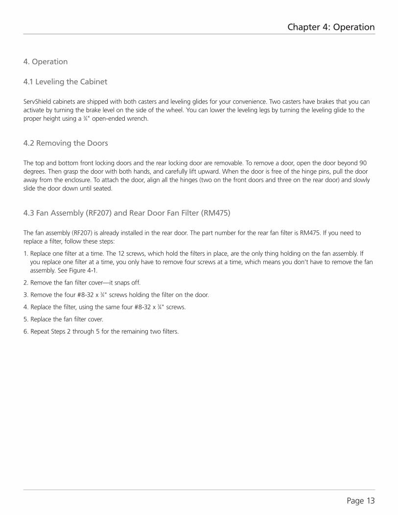
The fan assembly (RF207) is already installed in the rear door. The part number for the rear fan filter is RM475. If you need to replace a filter, follow these steps:
1. Replace one filter at a time. The 12 screws, which hold the filters in place, are the only thing holding on the fan assembly. If you replace one filter at a time, you only have to remove four screws at a time, which means you don’t have to remove the fan assembly. See Figure 4-1.
2. Remove the fan filter cover—it snaps off.
3. Remove the four #8-32 x 3⁄4" screws holding the filter on the door.
4. Replace the filter, using the same four #8-32 x 3⁄4" screws.
5. Replace the fan filter cover.
6. Repeat Steps 2 through 5 for the remaining two filters.
724-746-5500 | blackbox.com Page 14
Chapter 4: Operation•
•
Fan Filter Cover
Rear Door
Fan Assembly (RF207) Fan Grill (3)
#8-32 x 3⁄4" self-drilling and tapping screws (12)
Figure 4-1. Replacing a Rear Door Fan Filter.
4.4 Front Door Filter (RM476)
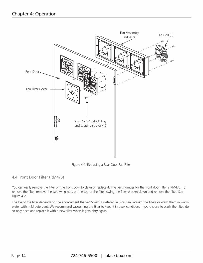
You can easily remove the filter on the front door to clean or replace it. The part number for the front door filter is RM476. To remove the filter, remove the two wing nuts on the top of the filter, swing the filter bracket down and remove the filter. See Figure 4-2.
The life of the filter depends on the environment the ServShield is installed in. You can vacuum the filters or wash them in warm water with mild detergent. We recommend vacuuming the filter to keep it in peak condition. If you choose to wash the filter, do so only once and replace it with a new filter when it gets dirty again.
724-746-5500 | blackbox.com Page 15
Chapter 4: Operation
Bottom Front Door
Filter
Filter Bracket
Wing Nut
Figure 4-2. Replacing the Front Door Filter.
724-746-5500 | blackbox.com Page 16
Chapter 4: Operation
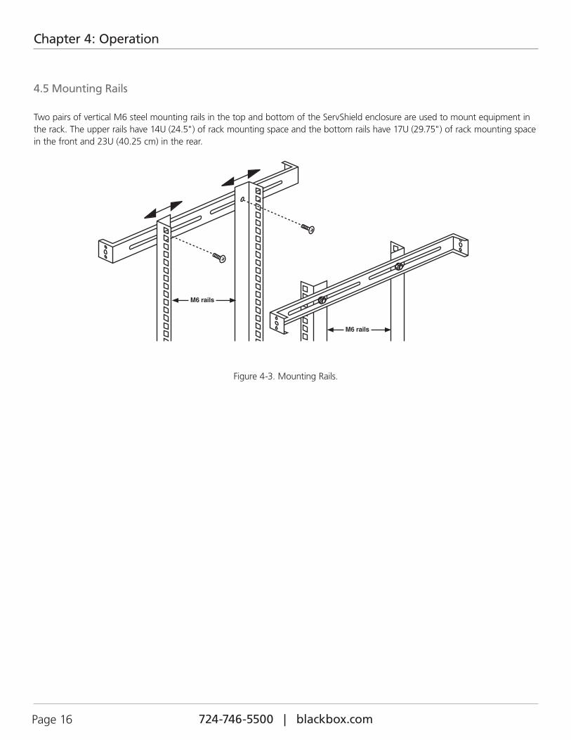
4.5 Mounting Rails
Two pairs of vertical M6 steel mounting rails in the top and bottom of the ServShield enclosure are used to mount equipment in the rack. The upper rails have 14U (24.5") of rack mounting space and the bottom rails have 17U (29.75") of rack mounting space in the front and 23U (40.25 cm) in the rear.
M6 rails
M6 rails
Figure 4-3. Mounting Rails.
724-746-5500 | blackbox.com Page 17
Chapter 5: Service
5. ServiceThe ServShield Enclosure should be repaired by personnel trained by Black Box, or returned to Black Box for repair or replacement. Contact Black Box Technical Support at 724-746-5500 or [email protected].

724-746-5500 | blackbox.com Page 18
NOTES

724-746-5500 | blackbox.com Page 19
NOTES

724-746-5500 | blackbox.com
BLACK BOX®
Black Box Tech Support: FREE! Live. 24/7.
Tech support the way it should be.
Great tech support is just 30 seconds away at 724-746-5500 or blackbox.com.
RM470A-R3, version 3
About Black BoxBlack Box provides an extensive range of networking and infrastructure products. You’ll find everything from cabinets and racks and power and surge protection products to media converters and Ethernet switches all supported by free, live 24/7 Tech support available in 30 seconds or less.
© Copyright 2011. Black Box Corporation.