Embed Size (px)
Citation preview

Installation and commissioning manualProtectIT Line differential protection terminal
REL 551*2.5

© Copyright 2006 ABB. All rights reserved.
Installation and commissioning manual Line differential protection terminal
REL 551*2.5
About this manualDocument No: 1MRK 506 151-UEN
Issued: December 2006Revision: C

COPYRIGHT
WE RESERVE ALL RIGHTS TO THIS DOCUMENT, EVEN IN THE EVENT THAT A PATENT IS ISSUED AND A DIFFERENT COMMERCIAL PROPRIETARY RIGHT IS REGISTERED. IMPROPER USE, IN PARTICULAR REPRODUCTION AND DISSEMINATION TO THIRD PARTIES, IS NOT PERMITTED.
THIS DOCUMENT HAS BEEN CAREFULLY CHECKED. HOWEVER, IN CASE ANY ERRORS ARE DETECTED, THE READER IS KINDLY REQUESTED TO NOTIFY THE MANUFACTURER AT THE ADDRESS BELOW.
THE DATA CONTAINED IN THIS MANUAL IS INTENDED SOLELY FOR THE CONCEPT OR PRODUCT DESCRIPTION AND IS NOT TO BE DEEMED TO BE A STATEMENT OF GUARAN-TEED PROPERTIES. IN THE INTERESTS OF OUR CUSTOMERS, WE CONSTANTLY SEEK TO ENSURE THAT OUR PRODUCTS ARE DEVELOPED TO THE LATEST TECHNOLOGICAL STAN-DARDS. AS A RESULT, IT IS POSSIBLE THAT THERE MAY BE SOME DIFFERENCES BETWEEN THE HW/SW PRODUCT AND THIS INFORMATION PRODUCT.
Manufacturer:
ABB Power Technologies ABSubstation Automation ProductsSE-721 59 VästeråsSwedenTelephone: +46 (0) 21 34 20 00Facsimile: +46 (0) 21 14 69 18www.abb.com/substationautomation

Contents
PageChapter
Chapter 1 Introduction ..................................................................... 1
Introduction to the installation and commissioning manual ................. 2About the complete set of manuals for a terminal .......................... 2About the installation and commissioning manual.......................... 2Intended audience .......................................................................... 3
General...................................................................................... 3Requirements ............................................................................ 3
Related documents......................................................................... 4Revision notes ................................................................................ 4Acronyms and abbreviations .......................................................... 4
Chapter 2 Safety information......................................................... 13
Warning signs .................................................................................... 14Caution signs ..................................................................................... 16Note signs.......................................................................................... 17
Chapter 3 Overview ........................................................................ 19
Commissioning and installation overview .......................................... 20
Chapter 4 Unpacking and checking the terminal ........................ 21
Receiving, unpacking and checking .................................................. 22
Chapter 5 Installing the terminal ................................................... 23
Overview............................................................................................ 24Mounting the terminal ........................................................................ 25
Mounting in a 19-inch rack ........................................................... 26Mounting in a 19-inch rack with an additional box type RHGS..... 27Mounting in a flush or semi-flush installation ................................ 28Mounting on a wall ....................................................................... 30
Mounting the terminal on a wall............................................... 31Preparing a wall mounted terminal for electrical installation.... 32
Making the electrical connections...................................................... 33Connecting the CT circuits............................................................ 33Connecting the auxiliary power, VT and signal connectors .......... 33Connecting to protective earth...................................................... 35Making the screen connection...................................................... 35
Installing the optical fibres ................................................................. 36

Contents
Installing the serial communication cable for RS485 SPA/IEC.......... 37RS485 serial communication module ........................................... 37Informative excerpt from EIA Standard RS-485 ........................... 39Data on RS485 serial communication module cable .................... 41
Installing the 56/64 kbit data communication cables.......................... 42
Chapter 6 Checking the external circuitry .................................... 45
Overview............................................................................................ 46Checking the CT and VT circuits ....................................................... 47Checking the power supply................................................................ 48Checking the binary I/O circuits ......................................................... 49
Binary input circuits....................................................................... 49Binary output circuits .................................................................... 49
Chapter 7 Energising the terminal................................................. 51
Overview............................................................................................ 52Energising the terminal ...................................................................... 53Checking the self supervision signals ................................................ 55
Reconfiguring the terminal............................................................ 55Setting the terminal time ............................................................... 55Checking the self supervision function ......................................... 55
Navigating the menus.............................................................. 55Self supervision HMI data............................................................. 56
Chapter 8 Configuring the 56/64 kbit data communication modules .............................................. 57
Configuring the fibre optical modem .................................................. 58Calculation of optical power budget ................................................... 59Configuring the short range fibre optical modem............................... 60Configuring the short range galvanic modem .................................... 64Configure the interface modules for V.36, X.21 and RS530.............. 66Configuring the interface modules for G.703 co-directional............... 68Fault tracing ....................................................................................... 69
Comfail function....................................................................... 69Explanation of contents in column 2 of table 42 ...................... 70
Configuring the transceiver 21-15xx .................................................. 73Co-directional operation..................................................................... 74Contra-directional operation............................................................... 76Configuring the transceiver 21-16xx .................................................. 78
X.21 operation .............................................................................. 78G.703 co-directional operation...................................................... 79
Chapter 9 Setting and configuring the terminal........................... 81
Contents
Overview............................................................................................ 82Entering settings through the local HMI............................................. 83Configuring the setting restriction of HMI function ............................. 84Activating the restriction of setting ..................................................... 85
Local HMI ..................................................................................... 85Serial communication, change of active group............................. 85Serial communication, setting....................................................... 85
Downloading settings and configuration from a PC........................... 86Establishing front port communication.......................................... 86Establishing rear port communication........................................... 86
Using the SPA/IEC rear port.................................................... 86Using LON rear port ................................................................ 87
Downloading the configuration and setting files ........................... 87
Chapter 10 Requirement of trig condition for disturbance report89
Requirement of trig condition for disturbance report.......................... 90
Chapter 11 Establishing connection and verifying the SPA/IEC-communication .............................................. 91
Entering settings ................................................................................ 92Entering SPA settings................................................................... 92Entering IEC settings.................................................................... 92
Verifying the communication.............................................................. 94Verifying SPA communication ...................................................... 94Verifying IEC communication........................................................ 94
Optical budget calculation for serial communication with SPA/IEC . 95
Chapter 12 Establishing connection and verifying the LON com-munication ..................................................................... 97
Reference .......................................................................................... 98Verification of the optical budget .................................................. 98
Optical budget calculation for serial communication with LON 98
Chapter 13 Verifying settings by secondary injection ................. 99
Overview.......................................................................................... 100Preparing for test ............................................................................. 102
Overview..................................................................................... 102Preparing the connection to the test equipment ......................... 102Setting the terminal in test mode ................................................ 103Connecting test equipment to the terminal ................................. 103Verifying the connection and the analog inputs.......................... 104

Contents
Releasing the function(s) to be tested ........................................ 105Checking the disturbance report settings ................................... 105Identifying the function to test in the technical reference manual ........................................... 106
Autorecloser (AR) ............................................................................ 107Preparing .................................................................................... 108Checking the AR functionality..................................................... 109Checking the reclosing condition ................................................ 109
Checking the Inhibit signal..................................................... 110Checking the closing onto a fault........................................... 110Checking the breaker not ready ............................................ 110Checking the synchro-check condition (for three-phase reclosing cycle) ............................ 110Checking the operation Stand-by and Off ............................. 110
Testing the multi-breaker arrangement....................................... 111Completing the test..................................................................... 111
Breaker failure protection (BFP) ...................................................... 112Verifying the settings .................................................................. 112Verifying the retrip setting ........................................................... 112
Checking the retrip function with retrip set to off.................... 112Checking the retrip function with current check..................... 112Checking the retrip function without current check ................ 113
Completing the test..................................................................... 113Broken conductor check (BRC) ....................................................... 114
Measuring the operate and time limit of set values .................... 114Communication channel test logic (CCHT)...................................... 115
Testing the logic.......................................................................... 115Current circuit supervision (CTSU) .................................................. 116Time delayed residual overcurrent protection (TEF)........................ 117
Checking the operate values of the current measuring elements ............................................... 117
Disturbance recorder (DR)............................................................... 120Event counter (CN) .......................................................................... 121Event function (EV) .......................................................................... 122Event recorder (ER) ......................................................................... 123Instantaneous non-directional overcurrent protection (IOC) ............ 124
Measuring the operate limit of set values ................................... 124Phase overcurrent protection ................................................ 124Residual overcurrent protection (non-dir.) ............................. 124
Completing the test..................................................................... 124Line differential protection, phase segregated (DIFL)...................... 125
Testing the line differential protection ......................................... 127Testing the charging current compensation................................ 129Completing the test..................................................................... 130
Supervision of AC input quantities (DA)........................................... 131Verifying the settings .................................................................. 131Completing the test..................................................................... 131
Supervision of mA input quantities (MI) ........................................... 132Verifying the settings .................................................................. 132Completing the test..................................................................... 133
Multiple command (CM)................................................................... 134Overload supervision (OVLD) .......................................................... 135
Measuring the operate and time limit of set values .................... 135
Contents
Pole discordance protection (PD) .................................................... 137Pulse counter logic for metering (PC).............................................. 138Setting lockout (HMI) ....................................................................... 139
Verifying the settings .................................................................. 139Completing the test..................................................................... 139
Four parameter setting groups (GRP) ............................................. 140Verifying the settings .................................................................. 140
Single command (CD) ..................................................................... 141Thermal phase overload protection (THOL) .................................... 142
Measuring the operate and time limit of set values .................... 142Testing the protection without external temperature compensation (NonComp) ................................ 142
Definite time non-directional overcurrent protection (TOC) ............ 144Measuring the operate limit of set values ................................... 144
Time delayed phase overcurrent ........................................... 144Time delayed residual overcurrent (non-dir.)......................... 144
Completing the test..................................................................... 145Tripping logic (TR) ........................................................................... 146
3ph operating mode.................................................................... 1461ph/3ph operating mode............................................................. 1461ph/2ph/3ph operating mode...................................................... 147Completing the test..................................................................... 148
Two step time delayed non-directional phase overcurrent protection (TOC2)......................................................... 149
Measuring the operate and time limit for set values ................... 149Measuring the operate limit of the low step overcurrent protection ............................................................................ 149Measuring the definite time delay of the low set stage.......... 149Measuring the inverse time delay of the low set stage.......... 149Measuring the operate limit of the high step overcurrent protection ............................................................................ 150
Completing the test..................................................................... 150Sudden change in phase current protection (SCC1) ...................... 151
Measuring the operate limit of set values ................................... 151Sudden change in current in any phase ................................ 151Dependability test .................................................................. 151Time delay test ...................................................................... 151Completing the test................................................................ 152
Sudden change in residual current protection (SCRC) ................... 153Measuring the operate limit of set values ................................... 153
Sudden change in residual current........................................ 153Dependability test .................................................................. 153Time delay test ...................................................................... 153Completing the test................................................................ 154
Undercurrent protection (UCP) ........................................................ 155Measuring the operate limit of set values ................................... 155
Undercurrent in any phase .................................................... 155Dependbility test .................................................................... 155Time delay test ...................................................................... 155Completing the test................................................................ 155
Phase overcurrent protection (OCP) ............................................... 156Measuring the operate limit of set values ................................... 156
Overcurrent in any phase ...................................................... 156

Contents
Dependability test .................................................................. 156Time delay test ...................................................................... 156Completing the test................................................................ 156
Residual overcurrent protection (ROCP) ......................................... 157Measuring the operate limit of set values ................................... 157
Residual overcurrent ............................................................. 157Dependability test .................................................................. 157Time delay test ...................................................................... 157Completing the test................................................................ 158
Chapter 14 Verifying the internal configuration........................... 159
Overview.......................................................................................... 160Testing the interaction of the distance protection ............................ 161
Chapter 15 Testing the protection system ................................... 163
Overview.......................................................................................... 164Testing the interaction of the distance protection ............................ 165
Chapter 16 Fault tracing and repair............................................... 167
Fault tracing ..................................................................................... 168Using information on the local HMI............................................. 168Using front-connected PC or SMS.............................................. 169
Repair instruction............................................................................. 171Repair support ................................................................................. 173

1
About this chapter Chapter 1Introduction
Chapter 1 Introduction
About this chapterThis chapter introduces the user to the manual.
2
Introduction to the installation and commissioning manual
Chapter 1Introduction
1 Introduction to the installation and commissioning manual
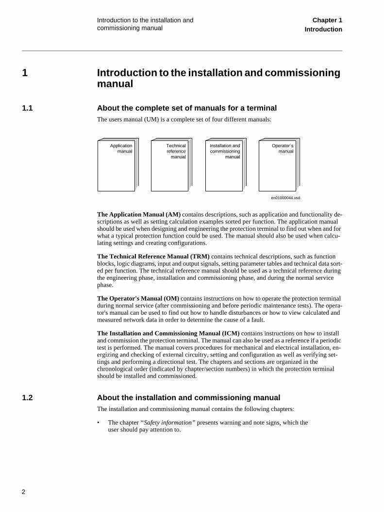
1.1 About the complete set of manuals for a terminalThe users manual (UM) is a complete set of four different manuals:
The Application Manual (AM) contains descriptions, such as application and functionality de-scriptions as well as setting calculation examples sorted per function. The application manual should be used when designing and engineering the protection terminal to find out when and for what a typical protection function could be used. The manual should also be used when calcu-lating settings and creating configurations.
The Technical Reference Manual (TRM) contains technical descriptions, such as function blocks, logic diagrams, input and output signals, setting parameter tables and technical data sort-ed per function. The technical reference manual should be used as a technical reference during the engineering phase, installation and commissioning phase, and during the normal service phase.
The Operator's Manual (OM) contains instructions on how to operate the protection terminal during normal service (after commissioning and before periodic maintenance tests). The opera-tor's manual can be used to find out how to handle disturbances or how to view calculated and measured network data in order to determine the cause of a fault.
The Installation and Commissioning Manual (ICM) contains instructions on how to install and commission the protection terminal. The manual can also be used as a reference if a periodic test is performed. The manual covers procedures for mechanical and electrical installation, en-ergizing and checking of external circuitry, setting and configuration as well as verifying set-tings and performing a directional test. The chapters and sections are organized in the chronological order (indicated by chapter/section numbers) in which the protection terminal should be installed and commissioned.
1.2 About the installation and commissioning manualThe installation and commissioning manual contains the following chapters:
• The chapter “Safety information” presents warning and note signs, which the user should pay attention to.
Applicationmanual
Technicalreference
manual
Installation andcommissioning
manual
Operator´smanual
en01000044.vsd

3
Introduction to the installation and commissioning manual
Chapter 1Introduction
• The chapter “Overview” gives an overview over the major tasks when installing and commissioning the terminal.
• The chapter “Unpacking and checking the terminal” contains instructions on how to receive the terminal.
• The chapter “Installing the terminal” contains instructions on how to install the terminal.
• The chapter “Checking the external circuitry” contains instructions on how to check that the terminal is properly connected to the protection system.
• The chapter “Energising the terminal” contains instructions on how to start-up the terminal.
• The chapter “Setting and configuring the terminal” contains instructions on how to download settings and configuration to the terminal.
• The chapter “Establishing connection and verifying the SPA/IEC-communica-tion” contains instructions on how to enter SPA/IEC settings and verifying the SPA/IEC communication.
• The chapter “Establishing connection and verifying the LON communication” contains a reference to another document.
• The chapter “Verifying settings by secondary injection” contains instructions on how to verify that each included function operates correctly according to the set values.
• The chapter “Primary injection testing” describes a test with primary current through the protected zone.
• The chapter “Testing the protection system” contains instructions on how to test that the terminal is in contact with the primary system.
• The chapter “Fault tracing and repair” contains instructions on how to fault trace.
1.3 Intended audience
1.3.1 GeneralThe installation and commissioning manual is addressing the installation, commissioning and maintenance personnel responsible for taking the protection into normal service and out of ser-vice.
1.3.2 RequirementsThe installation and commissioning personnel must have a basic knowledge in handling elec-tronic equipment. The commissioning and maintenance personnel must be well experienced in using protection equipment, test equipment, protection functions and the configured functional logics in the protection.

4
Introduction to the installation and commissioning manual
Chapter 1Introduction
1.4 Related documents
1.5 Revision notes
1.6 Acronyms and abbreviations
Documents related to REL 551*2.5 Identity number
Operator's manual 1MRK 506 150-UEN
Installation and commissioning manual 1MRK 506 151-UEN
Technical reference manual 1MRK 506 152-UEN
Application manual 1MRK 506 153-UEN
Buyer's guide 1MRK 506 179-BEN
Revision Description
C Minor updates in chapter:
• Configuring the 56/64 kbit data communication modules / Configuring the fibre optical modem
• Verifying settings by secondary injection / Line differential protection, phase segregated (DIFL)
AC Alternating Current
ACrv2 Setting A for programmable overvoltage IDMT curve, step 2
A/D converter Analog to Digital converter
ADBS Amplitude dead-band supervision
AIM Analog input module
ANSI American National Standards Institute
ASCT Auxiliary summation current transformer
ASD Adaptive Signal Detection
AWG American Wire Gauge standard
BIM Binary input module
BLKDEL Block of delayed fault clearing
BOM Binary output module
BR Binary transfer receive over LDCM
BS British Standard
BSR Binary Signal Receive (SMT) over LDCM
BST Binary Signal Transmit (SMT) over LDCM
BT Binary Transfer Transmit over LDCM

5
Introduction to the installation and commissioning manual
Chapter 1Introduction
C34.97
CAN Controller Area Network. ISO standard (ISO 11898) for serial communi-cation
CAP 531 Configuration and programming tool
CB Circuit breaker
CBM Combined backplane module
CCITT Consultative Committee for International Telegraph and Telephony. A United Nations sponsored standards body within the International Tele-communications Union.
CCS Current circuit supervision
CEM Controller area network emulation module
CIM Communication interface module
CMPPS Combined Mega Pulses Per Second
CO cycle Close-Open cycle
Co-directional Way of transmitting G.703 over a balanced line. Involves two twisted pairs making it possible to transmit information in both directions
Contra-directional Way of transmitting G.703 over a balanced line. Involves four twisted pairs of with two are used for transmitting data in both directions, and two pairs for transmitting clock signals
CPU Central Processor Unit
CR Carrier Receive
CRC Cyclic Redundancy Check
CRL POR carrier for WEI logic
CS Carrier send
CT Current transformer
CT1L1 Input to be used for transmit CT group 1line L1 in signal matrix tool
CT1L1NAM Signal name for CT-group 1line L1 in signal matrix tool
CT2L3 Input to be used for transmission of CT-group 2 line L3 to remote end
CT2N Input to be used for transmission of CT-group 2 neutral N to remote end.
CVT Capacitive voltage transformer
DAR Delayed auto-reclosing
db dead band
DBDL Dead bus dead line
DBLL Dead bus live line
DC Direct Current
DIN-rail Rail conforming to DIN standard
DIP-switch Small switch mounted on a printed circuit board

6
Introduction to the installation and commissioning manual
Chapter 1Introduction
DLLB Dead line live bus
DSP Digital signal processor
DTT Direct transfer trip scheme
EHV network Extra high voltage network
EIA Electronic Industries Association
EMC Electro magnetic compatibility
ENGV1 Enable execution of step one
ENMULT Current multiplier used when THOL is used for two or more lines
EMI Electro magnetic interference
ESD Electrostatic discharge
FOX 20 Modular 20 channel telecommunication system for speech, data and protection signals
FOX 512/515 Access multiplexer
FOX 6Plus Compact, time-division multiplexer for the transmission of up to seven duplex channels of digital data over optical fibers
FPGA Field Programmable Gate Array
FRRATED Rated system frequency
FSMPL Physical channel number for frequency calculation
G.703 Electrical and functional description for digital lines used by local tele-phone companies. Can be transported over balanced and unbalanced lines
G.711 Standard for pulse code modulation of analog signals on digital lines
GCM Communication interface module with carrier of GPS receiver module
GI General interrogation command
GIS Gas insulated switchgear.
GOOSE Generic Object Orientated Substation Event
GPS Global positioning system
GR GOOSE Receive (interlock)
HDLC protocol High level data link control, protocol based on the HDLC standard
HFBR connector type Fibre connector receiver
HMI Human-Machine Interface
HSAR High-Speed Auto-Reclosing
HV High voltage
HVDC High voltage direct current
HysAbsFreq Absolute hysteresis for over and under frequency operation
HysAbsMagn Absolute hysteresis for signal magnitude in percentage of Ubase
HysRelMagn Relative hysteresis for signal magnitude

7
Introduction to the installation and commissioning manual
Chapter 1Introduction
HystAbs Overexcitation level of absolute hysteresis as a percentage
HystRel Overexcitation level of relative hysteresis as a percentage
IBIAS Magnitude of the bias current common to L1, L2 and L3
IDBS Integrating dead-band supervision
IDMT Minimum inverse delay time
IDMTtmin Inverse delay minimum time in seconds
IdMin Operational restrictive characteristic, section 1 sensitivity, multiple Ibase
IDNSMAG Magnitude of negative sequence differential current
Idunre Unrestrained prot. limit multiple of winding1 rated current
ICHARGE Amount of compensated charging current
IEC International Electrical Committee
IEC 186A
IEC 60044-6 IEC Standard, Instrument transformers – Part 6: Requirements for pro-tective current transformers for transient performance
IEC 60870-5-103 Communication standard for protective equipment. A serial master/slave protocol for point-to-point communication
IEEE Institute of Electrical and Electronics Engineers
IEEE 802.12 A network technology standard that provides 100 Mbits/s on twisted-pair or optical fiber cable
IEEE P1386.1 PCI Mezzanine Card (PMC) standard for local bus modules. References the CMC (IEEE P1386, also known as Common Mezzanine Card) stan-dard for the mechanics and the PCI specifications from the PCI SIG (Special Interest Group) for the electrical
EMF Electro magnetic force
IED Intelligent electronic device
I-GIS Intelligent gas insulated switchgear
IL1RE Real current component, phase L1
IL1IM Imaginary current component, phase L1
IminNegSeq Negative sequence current must be higher than this to be used
INAMPL Present magnitude of residual current
INSTMAGN Magnitude of instantaneous value
INSTNAME Instance name in signal matrix tool
IOM Binary Input/Output module
IPOSIM Imaginary part of positive sequence current
IPOSRE Real component of positve sequence current
IP 20 Enclosure protects against solid foreign objects 12.5mm in diameter and larger but no protection against ingression of liquid according to IEC60529. Equivalent to NEMA type 1.

8
Introduction to the installation and commissioning manual
Chapter 1Introduction
IP 40 Enclosure protects against solid foreign objects 1.0mm in diameter or larger but no protection against ingression of liquid according to IEC60529.
IP 54 Degrees of protection provided by enclosures (IP code) according to IEC 60529. Dust protected. Protected against splashing water. Equiva-lent to NEMA type 12.
Ip>block Block of the function at high phase current in percentage of base
IRVBLK Block of current reversal function
IRV Activation of current reversal logic
ITU International Telecommunications Union
k2 Time multiplier in IDMT mode
kForIEEE Time multiplier for IEEE inverse type curve
LAN Local area network
LIB 520
LCD Liquid chrystal display
LDCM Line differential communication module
LDD Local detection device
LED Light emitting diode
LNT LON network tool
LON Local operating network
MAGN Magnitude of deadband value
MCB Miniature circuit breaker
MCM Mezzanine carrier module
MIM Milliampere Input Module
MIP
MPPS
MPM Main processing module
MV Medium voltage
MVB Multifunction vehicle bus. Standardized serial bus originally developed for use in trains
MVsubEna Enable substitution
NegSeqROA Operate angle for internal/external negative sequence fault discrimina-tor.
NSANGLE Angle between local and remote negative sequence currents
NUMSTEP Number of steps that shall be activated
NX
OCO cycle Open-Close-Open cycle
PCI Peripheral Component Interconnect

9
Introduction to the installation and commissioning manual
Chapter 1Introduction
PCM Pulse code modulation
PISA Process interface for sensors & actuators
PLD Programmable Logic Device
PMC
POTT Permissive overreach transfer trip
PPS Precise Positioning System
Process bus Bus or LAN used at the process level, that is, in near proximity to the measured and/or controlled components
PSM Power supply module
PST Parameter setting tool
PT ratio Potential transformer or voltage transformer ratio
PUTT Permissive underreach transfer trip
R1A Source resistance A (near end)
R1B Source resistance B (far end)
RADSS Resource Allocation Decision Support System
RASC Synchrocheck relay, from COMBIFLEX range.
RCA Functionality characteristic angle
REVAL Evaluation software
RFPP Resistance of phase-to-phase faults
RFPE Resistance of phase-to-earth faults
RISC Reduced instruction set computer
RMS value Root mean square value
RS422 A balanced serial interface for the transmission of digital data in point-to-point connections
RS485 Serial link according to EIA standard RS485
RS530 A generic connector specification that can be used to support RS422, V.35 and X.21 and others
RTU Remote Terminal Unit
RTC Real Time Clock
SA Substation Automation
SC Switch or push-button to close
SCS Station control system
SLM Serial communication module. Used for SPA/LON/IEC communication
SMA connector Sub Miniature version A connector
SMS Station monitoring system
SPA Strömberg Protection Acquisition, a serial master/slave protocol for point-to-point communication

10
Introduction to the installation and commissioning manual
Chapter 1Introduction
SPGGIO Single Point Gxxxxx Generic Input/Output
SRY Switch for CB ready condition
ST3UO RMS voltage at neutral point
STL1 Start signal from phase L1
ST Switch or push-button to trip
SVC Static VAr compensation
t1 1Ph Open time for shot 1, single phase
t1 3PhHS Open time for shot 1, high speed reclosing three phase
tAutoContWait Wait period after close command before next shot
tCBCLosedMin Minimum time that the circuit breaker must be closed before new sequence is permitted
tExtended t1 Open time extended by this value if Extended t1 is true
THL Thermal Overload Line cable
THOL Thermal overload
tInhibit Reset reclosing time for inhibit
tPulse Pulse length for single command outputs
TP Logic Pulse Timer
tReporting Cycle time for reporting of counter value
tRestore Restore time delay
TCS Trip circuit supervision
TNC connector Type of bayonet connector, like BNC connector
TPZ, TPY, TPX, TPS Current transformer class according to IEC
tReclaim Duration of the reclaim time
TRIPENHA Trip by enhanced restrained differential protection
TRIPRES Trip by restrained differential protection
TRL1 Trip signal from phase 1
truck Isolator with wheeled mechanism
tSync Maximum wait time for synchrocheck OK
TTRIP Estimated time to trip (in minutes)
UBase Base setting for phase-phase voltage in kilovolts
U/I-PISA Process interface components that delivers measured voltage and cur-rent values
UNom Nominal voltage in % of UBase for voltage based timer
UPS Measured signal magnitude (voltage protection)
UTC Coordinated Universal Time. A coordinated time scale, maintained by the Bureau International des Poids et Mesures (BIPM), which forms the basis of a coordinated dissemination of standard frequencies and time signals

11
Introduction to the installation and commissioning manual
Chapter 1Introduction
V.36 Same as RS449. A generic connector specification that can be used to support RS422 and others
VDC Volts Direct Current
WEI Week-end infeed logic
VT Voltage transformer
VTSZ Block of trip from weak-end infeed logic by an open breaker
X1A Source reactance A (near end)
X1B Source reactance B (far end)
X1L Positive sequence line reactance
X.21 A digital signalling interface primarily used for telecom equipment
XLeak Winding reactance in primary ohms
XOL Zero sequence line reactance
ZCOM-CACC Forward overreaching zone used in the communication scheme
ZCOM-CR Carrier Receive Signal
ZCOM-TRIP Trip from the communication scheme
ZCOM-LCG Alarm Signal LIne-check Guard

12
Introduction to the installation and commissioning manual
Chapter 1Introduction

13
About this chapter Chapter 2Safety information
Chapter 2 Safety information
About this chapterThis chapter contains safety information. Warning signs are presented which attend the user to be careful during certain operations in order to avoid human injuries or damage to equipment

14
Warning signs Chapter 2Safety information
1 Warning signs
Warning!Strictly follow the company and country safety regulations. Working in a high voltage environ-ment requires serious approach to avoid human injuries and damage to equipment.
Warning!Do not touch circuitry during operation. Potentially lethal voltages and currents are present.
Warning!Always avoid to touch the circuitry when the cover is removed. The product contains electronic circuitries which can be damaged if exposed to static electricity (ESD). The electronic circuit-ries also contain high voltage which is lethal to humans.
Warning!Always use suitable isolated test pins when measuring signals in open circuitry. Potentially le-thal voltages and currents are present.
Prohibition!Never connect or disconnect a wire and/or a connector to or from a IED during normal opera-tion. Hazardous voltages and currents are present that may be lethal. Operation may be disrupt-ed and IED and measuring circuitry may be damaged.
Warning!Always connect the IED to protective earth, regardless of the operating conditions. This also applies to special occasions such as bench testing, demonstrations and off-site configuration. Operating the IED without proper earthing may damage both IED and measuring circuitry and may cause injuries in case of an accident.
Warning!Never disconnect a secondary connection of current transformer circuit without short-circuiting the transformer’s secondary winding. Operating a current transformer with the secondary winding open will cause a massive potential build-up that may damage the transformer and may cause injuries to humans.

15
Warning signs Chapter 2Safety information
Warning!Never remove any screw from a powered IED or from a IED connected to powered circuitry. Potentially lethal voltages and currents are present.

16
Caution signs Chapter 2Safety information
2 Caution signs
Caution!Always transport modules using certified conductive bags. Always handle modules using a con-ductive wrist strap connected to protective ground and on a suitable antistatic surface. Electro-static discharge (ESD) may cause damage to the module.
Caution!Do not connect live wires to the IED. Internal circuitry may be damaged
Caution!Always use a conductive wrist strap connected to protective ground when replacing modules. Electrostatic discharge (ESD) may damage the module and IED circuitry.
Caution!Take care to avoid electrical shock if accessing wiring and connection IEDs when installing and commissioning.
Caution!Changing the active setting group will inevitably change the IED’s operation. Be careful and check regulations before making the change.

17
Note signs Chapter 2Safety information
3 Note signs
Note!The protection assembly is designed for a maximum continuous current of four times rated val-ue.
Note!Activating the setting lockout function, which prevents unauthorised changes of the settings, without proper configuration may seriously affect the IED’s operation.

18
Note signs Chapter 2Safety information

19
About this chapter Chapter 3Overview
Chapter 3 Overview
About this chapterThis chapter introduces the user to the installation and commissioning tasks.

20
Commissioning and installation overview Chapter 3Overview
1 Commissioning and installation overviewThe settings for each function must be calculated before the commissioning task can start. A configuration, made in the configuration and programming tool, must also be available if the ter-minal does not have a factory configuration downloaded.
The terminal is unpacked and visually checked. It is preferably mounted in a cubicle or on a wall. The connection to the protection system has to be checked in order to verify that the installation was successful.
The installation and commissioning task starts with configuring the digital communication mod-ules, if included. The terminal can then be configured and set, which means that settings and a configuration has to be applied if the terminal does not have a factory configuration downloaded. Then the operation of each included function according to applied settings has to be verified by secondary injection. A complete check of the configuration can then be made. A conformity test of the secondary system has also to be done. When the primary system has been energised a di-rectionality check should be made.

21
About this chapter Chapter 4Unpacking and checking the
terminal
Chapter 4 Unpacking and checking the terminal
About this chapterThis chapter contains instructions on how to receive the terminal.

22
Receiving, unpacking and checking Chapter 4Unpacking and checking the
terminal
1 Receiving, unpacking and checkingProcedure1. Remove the transport casing.
2. Visually inspect the terminal.
3. Check that all items are included in accordance with the delivery documents.
The user is requested to check that all software functions are included ac-cording to the delivery documents after the terminal has been energised.
4. Check for transport damages.
In case of transport damage appropriate action must be taken against the latest carrier and the nearest ABB office or representative should be in-formed. ABB should be notified immediately if there are any discrepan-cies in relation to the delivery documents.
Store the terminal in the original transport casing in a dry and dust free place, if the terminal is not to be installed or commissioned immediately. Observe the environmental requirements stated in the technical data.

23
About this chapter Chapter 5Installing the terminal
Chapter 5 Installing the terminal
About this chapterThis chapter describes how to install the terminal.

24
Overview Chapter 5Installing the terminal
1 OverviewThe mechanical and electrical environmental conditions at the installation site must be within permissible range according to the technical data of the terminal. Dusty, damp places, places li-able to rapid temperature variations, powerful vibrations and shocks, surge voltages of high am-plitude and fast rise time, strong induced magnetic fields or similar extreme conditions should be avoided.
Sufficient space must be available in front of and at rear of the terminal to allow access for main-tenance and future modifications. Flush mounted terminals should be mounted so that terminal modules can be added and replaced without excessive demounting.

25
Mounting the terminal Chapter 5Installing the terminal
2 Mounting the terminalMost of the REx 5xx terminals can be rack, flush, semi-flush or wall mounted with the use of different mounting kits. An additional box of type RHGS can be mounted to one side of a 1/2 or 3/4 terminal. The 19-inch 1/1 wide terminal cannot be semi-flush mounted because the mount-ing distance frame will cover the ventilation openings at the top and bottom.
A suitable mounting kit is available. Mounting kits include instruction sheets and all parts need-ed including screws. The following mounting kits are available:
• 19-inch rack mounting kits, 1/2, 3/4 and 1/1 terminal width variants. See section 2.1 "Mounting in a 19-inch rack".
• Side-by-side mounting kit. See section 2.2 "Mounting in a 19-inch rack with an additional box type RHGS".
• Flush mounting kit. See section 2.3 "Mounting in a flush or semi-flush installa-tion".
• Semi-flush mounting kit. See section 2.3 "Mounting in a flush or semi-flush in-stallation".
• Wall mounting kit. See section 2.4 "Mounting on a wall".

26
Mounting the terminal Chapter 5Installing the terminal
2.1 Mounting in a 19-inch rack
Figure 1: 19-inch rack mounting
PosNo Description
1 and 4 Mounting angle
2 and 3 TORX T20 screws
(98000037)
1
2
3
4

27
Mounting the terminal Chapter 5Installing the terminal
Procedure1. Carefully fasten the mounting angles to the sides of the terminal.
Use the TORX T20 screws available in the mounting kit.
2. Place the terminal assembly in the rack.
3. Fasten the mounting angles with appropriate screws.
2.2 Mounting in a 19-inch rack with an additional box type RHGSMake sure a side-by-side mounting kit and a suitable 19-inch rack mounting kit are available before proceeding.
Assemble the two terminals by using a side-by-side mounting kit. Then mount the brackets and install the assembled terminals in the rack as described in section 2.1 "Mounting in a 19-inch rack".
Figure 2: Side-by-side assembly
Procedure1. Place the two terminals next to each other on a flat surface.
PosNo Description
1 Side-by-side mounting plate
2 Screws (TORX T20)
3 Mounting angle
xx03000028.vsd
3
1
2

28
Mounting the terminal Chapter 5Installing the terminal
2. Fasten a side-by-side mounting plate (PosNo 1).
Use four of the delivered screws.
3. Carefully turn the two terminals up-side down.
4. Fasten the second side-by-side mounting plate.
Use the remaining four screws.
5. Follow the instructions in section 2.1 "Mounting in a 19-inch rack" to mount the mounting angles (PosNo 5) and install the side-by-side assembly in the rack.
2.3 Mounting in a flush or semi-flush installationMake sure a flush or semi-flush mounting kit is available before proceeding.
The procedure for flush and semi-flush mounting is mainly the same. In semi-flush mounts a distance frame is added. The delivered mounting seal is only necessary to fulfil IP 54.

29
Mounting the terminal Chapter 5Installing the terminal
Figure 3: Flush and semi-flash mounting
PosNo Description
1 Sealing strip
2 Distance frame (only for semi-flush)
3 Sealing strip for distance frame (only for semi-flush)
4 Side holder
5 Groove
6 Locking screw (TORX T10)
xx00000129.eps
12
3
4
56
Note!Flush or semi-flush mount cannot be used for side-by-side mounted terminals when IP 54 must be fulfilled.
30
Mounting the terminal Chapter 5Installing the terminal
Procedure1. Cut the sealing strip in appropriate lengths.
The strip is delivered with the mounting kit. In the semi-flush mounting kit two strips are delivered, one for the terminal and one self-adhering for the distance frame. The length of the strip is enough for the largest avail-able terminal.
Cut the strip into four, one part for each side of the terminal. When cut-ting, make sure no gaps will be present between each part. Preferably, seal the joints at the corners (posNo 1).
Repeat the procedure for the self-adhering strip which are to be adhered to the distance frame.
2. Dispose the strip remains.
The remains should be source separated as soft plastic.
3. Carefully press the cut strips into the front panel groove.
4. Adhere the cut strips (posNo 3) to the edge of the distance frame (posNo 2).
semi-flush mounting only.
5. Make a panel cut-out.
See the Technical reference manual for cut-out dimensions.
6. Insert the terminal into the cut-out.
7. Add and lock the side holders (PosNo 4) to the terminal.
Thread a side holder into the groove (posNo 5) at the back end of the ter-minal. Insert and lightly fasten the locking screw (posNo 6). Next, thread a side holder on the other side of the terminal, and lightly fasten its lock-ing screw.
Repeat this with the remaining two side holders.
8. Lock the terminal to the cut-out.
Firmly tighten the locking screws. It is important that all four side holder locking screws are tightened the same in order to maintain a good and even seal in IP 54 environments.
2.4 Mounting on a wall The mounting bars are prepared for adding DIN-rails or equivalent above and below the mount-ed terminal. If used, make sure all necessary parts such as rails and terminal blocks are available before starting. Make sure the wall mounting kit is available.

31
Mounting the terminal Chapter 5Installing the terminal
Figure 4: Wall mounting
2.4.1 Mounting the terminal on a wall
Procedure1. Mount the bars (posNo 1) onto the wall.
See the Technical reference manual for measurements.
Depending on the wall different preparations may be needed, like drilling and inserting plastic or expander plugs (concrete/plasterboard walls) or threading (metal sheet wall).
2. Mount the DIN-rail(s) on the mounting bars.
3. Mount the terminal blocks on the DIN-rail(s).
It is much easier to do this without the unit in place.
PosNo Description
1 Mounting bar
2 Side plate
xx00000130.eps
1
2
32
Mounting the terminal Chapter 5Installing the terminal
4. Make all external electrical connections to the terminal blocks.
It is much easier to do this without the unit in place.
5. Mount the side plates (posNo 2) to the terminal.
6. Mount the terminal to the mounting bars.
2.4.2 Preparing a wall mounted terminal for electrical installation
Procedure1. Remove all screws from one side plate.
2. Remove two screws from the other side plate.
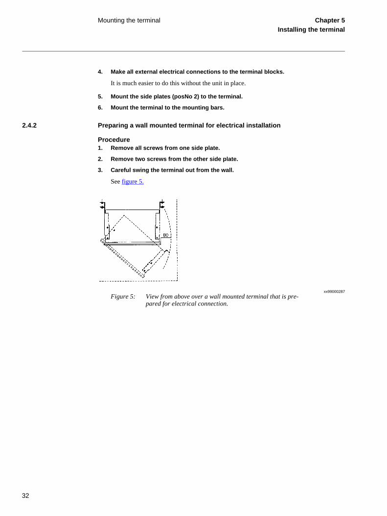
3. Careful swing the terminal out from the wall.
See figure 5.
xx99000287Figure 5: View from above over a wall mounted terminal that is pre-
pared for electrical connection.

33
Making the electrical connections Chapter 5Installing the terminal
3 Making the electrical connectionsAlways make sure established guidelines for this type of terminal is followed during installation. When necessary use screened twisted-pair cables to minimize susceptibility. Otherwise use any kind of regular nonscreened tinned cable or equivalent.
When using screened cabling always use 360° full screen cable bushings to ensure screen cou-pling. Ensure that all signals of a single circuit are in the same single cable. Avoid mixing current and voltage measuring signals in the same cable. Also use separate cables for control and mea-suring circuits.
3.1 Connecting the CT circuitsCTs are connected using back-side mounted screw connectors.
Use a solid conductor with a cross section area between 2.5-6 mm2 (AWG14-10) or a stranded conductor with a cross section area between 2.5-4 mm2.
If the terminal is equipped with a test-switch of type RTXP 24 COMBIFLEX wires with 20 A sockets must be used to connect the CT circuits.
3.2 Connecting the auxiliary power, VT and signal connectorsAuxiliary power, VTs and signals are connected using COMBICON (Phoenix technology) plug-in screw connectors.
Procedure1. Connect signals to the COMBICON plug.
2. Plug the connector to the corresponding back-side mounted recept-able.
3. Lock the plug to the receptable by fastening the lock screws.
Use a solid or stranded conductor with a cross section area between 0.5-2.5 mm2 (AWG20-14). Use a ferrule with plastic collar to connect two conductors, cross section area between 0.5-1.5 mm2 (AWG20-16).
Note!Screened and twisted pair cables are a requirement for galvanic communications in application with 56/64 kbit/s. The screen must be earthed according to figures in the sections “Making the screen connection” and “Installing the communication cables”.

34
Making the electrical connections Chapter 5Installing the terminal
Figure 6: Voltage connector, showing connection point X20:5
Figure 7: Connected cables with ferrules
Where: 1 is ferrule
X20
X20:5
(98000035)
1

35
Making the electrical connections Chapter 5Installing the terminal
If the terminal is equipped with a test-switch of type RTXP 24 COMBIFLEX wires with 20 A sockets must be used to connect the VT circuits and the auxiliary power.
3.3 Connecting to protective earthConnect the unit to the earthing bar of the cubicle with a green/yellow conductor, cross section at least 1.5 mm2 (AWG16), connected to the protective earth connector at the back of the termi-nal.
3.4 Making the screen connectionWhen using screened cables always make sure screens are earthed and connected in according to applicable engineering methods. This may include checking for appropriate earthing points near the terminal, for instance, in the cubicle and/or near the source of measuring. Ensure that earth connections are made with short (max. 10 cm) conductors of an adequate cross section, at least 6 mm2 (AWG10) for single screen connections.
en03000087.vsd
Rx
Tx
Sc
Lc
Tx
Rx
Sc
LcCc
IED ExternalEquipment

36
Installing the optical fibres Chapter 5Installing the terminal
4 Installing the optical fibresConnectors are generally color coded; connect blue or dark grey cable connectors to blue or dark grey (receive) back-side connectors. Connect black or grey cable connectors to black or grey (transmit) back-side connectors.
Caution!The fibre optical cables are very sensitive to handling. Do not bend too sharply. The minimum curvature radius is 15 cm for the plastic fibre cables and 25 cm for the glass fibre cables. If cable straps are used to fix the cables, apply with loose fit.
Always hold the connector, never the cable, when connecting or disconnecting optical fibres. Do not twist, pull or bend the fibre. Invisible damage may increase fibre attenuation thus making communication impossible.
Note!Please, strictly follow the instructions from the manufacturer for each type of optical ca-bles/connectors.

37
Installing the serial communication cable for RS485 SPA/IEC
Chapter 5Installing the terminal
5 Installing the serial communication cable for RS485 SPA/IEC
5.1 RS485 serial communication module
Figure 8: Pin arrangement on modem terminal. Baud rate: 9600
The distance between earth points should be < 100 m, see figure 9. Only the outer shielding is connected to the protective earth at the terminal. The inner and outer shieldings are connected to the protective earth at the external equipment. Use insulating tape for the inner shield to pre-vent contact with the protective earth. Make sure that the terminals are properly earthed with as short connections as possible from the earth screw, for example to an earthed frame.
The terminal and the external equipment should preferably be connected to the same battery.
Where:
A Signal A
B Signal B
1) Do not use
GND Ground
en03000109.vsd
AB
1)1)
1)
GND
Up

38
Installing the serial communication cable for RS485 SPA/IEC
Chapter 5Installing the terminal
Figure 9: Communication cable installation
en03000111.vsd
Cc
ExternalEquipment (PC)Terminal
A
PE
B
PE
A B
PE 1)
A B
PE
Terminal
Cc1)
Where:
1 The inner shields shall be connected together (with an isolated terminal block) and only have one earthing point in the whole system, preferably at the external equipment (PC).
The outer shield shall be connected to Protective Earth (PE) in every cable end i.e. to PE at all relay terminals and to PE at External equipment (PC). The first terminal will have only one cable end but all others of course two.
Cc Communication cable
PE Protective earth screw

39
Installing the serial communication cable for RS485 SPA/IEC
Chapter 5Installing the terminal
Figure 10: Cable contact, Phoenix: MSTB2.5/6-ST-5.08 1757051
The EIA standard RS-485 specifies the RS485 network. An informative excerpt is given in sec-tion 5.2.
5.2 Informative excerpt from EIA Standard RS-485Informative excerpt from EIA Standard RS-485 - Electrical Characteristics of Generators and Receivers for Balanced Digital Multipoint Systems
RS-485 Wire - Media dependent Physical layer
Where:
1 is cable
2 is screw
en03000110.vsd
1
2
1 Normative references
EIA Standard RS-485 - Electrical Characteristics of Generators and Receivers for Balanced Digital Multipoint Systems
2 Transmission method
RS-485 differential bipolar signaling
2.1 Differential signal levels
Two differential signal levels are defined:
A+ =line A positive with respect to line B
A- =line A negative with respect to line B
2.2 Galvanic isolation
The RS485 circuit shall be isolated from earth by:
Riso ≥ 10 MΩ
Ciso ≤ 10 pF

40
Installing the serial communication cable for RS485 SPA/IEC
Chapter 5Installing the terminal
Three isolation options exist:
a) The entire node electronics can be galvanically isolated
b) The bus interface circuit can be isolated form the rest of node electronics by optoisola-tors, transformer coupling or otherwise.
c) The RS485 chip can include built-in isolation
2.3 Bus excitation and signal conveyance
2.3.1 Requirements
a) The RS485 specification requires the Signal A and Signal B wires.
b) Each node also requires (5 V) Excitation of the RS485 termination network.
c) Vim - the common mode voltage between any pair of RS485 chips may not exceed 10 V.
d) A physical ground connection between all RS485 circuits will reduce noise.
2.3.2 Bus segment termination network
The termination network below required at each end of each Bus Ph-segment.
Figure 11: RS-485 bus segment termination
ExV is supplied by the Node at end of the Bus Segment
The specifications of the components are:
a) Ru + 5 V to Signal B = 390 Ω, 0.25 W ±2.5%
b) Rt Signal B to Signal A = 220 Ω, 0.25 W ±2.5%
c) Rd Signal A to GND = 390 Ω, 0.25 W ±2.5%
2.3.3 Bus power distribution
The end node in each Ph-segment applies 5 V bus excitation power to the Termination network via the Excitation pair (ExV+ and GND) used in the Type 3 Physical layer specification.
en03000112.vsd
ExV+
Signal B
Signal A
DGND
Ru = 390 ohm1/4 W, 2%
Rt = 220 ohm1/4 W, 2%
Rd = 390 ohm1/4 W, 2%
ExV is supplied by the Node at end of the Bus Segment

41
Installing the serial communication cable for RS485 SPA/IEC
Chapter 5Installing the terminal
5.3 Data on RS485 serial communication module cable
Type: Twisted-pair S-STP (Screened – Screened Twisted Pair)
Shield: Individual foil for each pair with overall copper braid
Length: Maximum 100 m from one system earth to the next system earth (includes length from platform point to system earth on both sides)
Temp: According to application
Impedance: 120 Ω
Capacitance: Less than or equal to 42 pF/m
Example: Belden 9841

42
Installing the 56/64 kbit data communication cables
Chapter 5Installing the terminal
6 Installing the 56/64 kbit data communication cablesWhen using galvanic connection between protection terminal and communication equipment or point to point galvanic connection between two protection terminals it is essential that the cable installation is carefully done. This is true regardless of type of module used, G.703, V.36, short range galvanic etc., only the possible length of the cable differs. The factors that must be taken into account are the susceptibility for noise disturbance, due to that the levels of the communi-cation signal are very low.
For best result a cable with twisted pairs and double screens should be used, one screen for each twisted pair and one surrounding all pairs. Each signal shall utilizie its own twisted pair as in figure 12. The screen for each separate pair shall be connected to internal screen or ground con-nection of equipment in one and the same end only, if available, or in other case connected to earth close to the equipment.
The outer screen surrounding all pairs shall be connected to a solid earth at each end close to the equipment.
Note also that recommendation about cable lengths given for modules according ITU/EIA inter-face, excluding the short range galvanic module, are under the assumption that the two devices, the protection terminal and the communication terminal, are within the same building and that the earthing system of the building is of good quality. It also presumes that the environment is relatively free from electromagnetic interference.

43
Installing the 56/64 kbit data communication cables
Chapter 5Installing the terminal
Figure 12: Communication cable installation
Cc Communication cable
Lc Line connector
Rx Receive input
Sc Screen (or earth/ground) connection
Tx Transmit output
en03000087.vsd
Rx
Tx
Sc
Lc
Tx
Rx
Sc
LcCc
IED ExternalEquipment

44
Installing the 56/64 kbit data communication cables
Chapter 5Installing the terminal

45
About this chapter Chapter 6Checking the external circuitry
Chapter 6 Checking the external circuitry
About this chapterThis chapter describes what to check and which checks that should be made to ensure a correct connection to the external circuitry, such as auxiliary power supply, CT’s and VT’s. These checks must be made with the protection terminal de-energised.

46
Overview Chapter 6Checking the external circuitry
1 OverviewThe user must check the installation which includes verifying that the terminal is connected to the other parts of the protection system. This is done with the terminal and all connected circuits de-energised.

47
Checking the CT and VT circuits Chapter 6Checking the external circuitry
2 Checking the CT and VT circuitsCheck that the wiring is in strict accordance with the supplied wiring diagram.
Test the circuitry. The following tests are recommended:
• Polarity check.• CT circuit current measurement (primary injection test).• Earthing check.
The polarity check verifies the integrity of the circuits and the phase relationship. The check should be performed as close as possible to the terminal.
The primary injection test verifies the CT ratio and the wiring all the way through from the pri-mary system to the terminal. Injection must be performed for each phase-to-neutral circuit and each phase-to-phase pair. In each case currents in all phases and the neutral line are measured.
Note!Do not continue further until any errors are corrected.

48
Checking the power supply Chapter 6Checking the external circuitry
3 Checking the power supplyCheck that the value of the auxiliary supply voltage remains within the permissible range under all operating conditions. Check that the polarity is correct.

49
Checking the binary I/O circuits Chapter 6Checking the external circuitry
4 Checking the binary I/O circuits
4.1 Binary input circuitsPreferably, disconnect the binary input connector from the binary input cards. Check all con-nected signals so that both input level and polarity are in accordance with the terminal’s speci-fications.
4.2 Binary output circuitsPreferably, disconnect the binary output connector from the binary output cards. Check all con-nected signals so that both load and polarity are in accordance with the terminal’s specifications.

50
Checking the binary I/O circuits Chapter 6Checking the external circuitry

51
About this chapter Chapter 7Energising the terminal
Chapter 7 Energising the terminal
About this chapterThis chapter describes the start up sequence and what to check after the terminal has been eneri-gsed.
52
Overview Chapter 7Energising the terminal
1 OverviewBefore the procedures in this chapter can be carried out the connection to external circuitry must have been checked which ensures that the installation was made correctly.
The user must energise the power supply to the terminal to start it up. This could be done in num-ber of ways, from energising a whole cubicle to energising a single terminal. The user should reconfigure the terminal to activate the hardware modules in order to enable the self supervision function detect eventual hardware errors. Then the terminal time must be set. The self supervi-sion function should also be checked to verify that the terminal unit operates properly. The user could also check the software version, the terminals serial number and the installed modules and their ordering number to ensure that the terminal is according to delivery and ordering specifi-cations.

53
Energising the terminal Chapter 7Energising the terminal
2 Energising the terminalWhen the terminal is energised the window on the local HMI remains dark. After 10 seconds the green LED starts flashing and after approximately 30 seconds the window lights up. After an-other 10 seconds the window displays ‘Terminal Startup’ and after about 30 seconds the main menu is displayed. The upper row should indicate ‘Ready’. A steady green light indicates a suc-cessful startup.
Figure 13: Typical terminal startup sequence
If the upper row in the window indicates ‘Fail’ instead of ‘Ready’ and the green LED is flashing an internal failure in the terminal has been detected. See the self supervision function in this chapter to investigate the fault.
After startup the appearance of the local HMI should be as shown in figure 14.
1 Terminal energised. Liquide Crystal Display (LCD) is dark.
2 Green Light Emitting Diod (LED) starts flashing
3 LCD lights up
4 "Terminal startup" is displayed
5 The main menu is displayed. A steady green light indicates a successful startup.
xx02000679.vsd
t (s)0 3010 40 70
1 5432

54
Energising the terminal Chapter 7Energising the terminal
Figure 14: Example of the local HMI531.
en00000422.vsd
E
C
ReadyREx 5xx Ver X.XC=QuitE=Enter menu
Start Trip
Push buttons
green yellow red
LEDs
Liquid Crystal Displayfour rows16 characters/row
Optical connectorfor local PC

55
Checking the self supervision signals Chapter 7Energising the terminal
3 Checking the self supervision signals
3.1 Reconfiguring the terminalI/O modules configured as logical I/O modules (BIM, BOM, IOM, DCM, IOPSM or MIM) are supervised. Not configured I/O modules are not supervised.
Each logical I/O module has an error flag that is set if anything is wrong with any signal or the whole module. The error flag is also set when there is no physical I/O module of the correct type present in the connected slot.
Procedure1. Browse to the ‘Reconfigure’ menu.
The Reconfigure menu is located in the local HMI under:
Configuration/I/O-modules/Reconfigure
2. Select ‘Yes’ and press ‘E’.
3.2 Setting the terminal timeThis procedure describes how to set the terminal time.
1. Display the set time dialog.
Navigate the menus to:
Settings/Time
Press the E button to enter the dialog.
2. Set the date and time.
Use the Left and Right arrow buttons to move between the time and date values (year, month, day, hours, minutes and seconds). Use the Up and Down arrow buttons to change the value.
3. Confirm the setting.
Press the E button to set the calendar and clock to the new values.
3.3 Checking the self supervision function
3.3.1 Navigating the menusThis procedure describes how to navigate the menus in order to find the reason of an internal failure when indicated by the flashing green LED of the HMI module.

56
Checking the self supervision signals Chapter 7Energising the terminal
Procedure1. Display the self supervision menu.
Navigate the menus to:
TerminalReportSelfSuperv
2. Scroll the supervision values to identify the reason of the failure.
Use the Left and/or Right arrow buttons to scroll between values.
3.4 Self supervision HMI dataTable 1: Output signals for the self supervision function
Indicated result Possible reason Proposed action
InternFail = OK No problem detected. None.
InternFail = Fail A failure has occurred. Check the rest of the indicated results to find the fault.
InternWarning = OK No problem detected. None.
InternWarning = Warning A warning has been issued.
Check the rest of the indicated results to find the fault.
MPM-modFail = OK No problem detected. None.
MPM-modFail = Fail The main processing mod-ule has failed.
Contact your ABB representative for service.
MPM-modWarning = OK No problem detected. None.
MPM-modWarning = Warning
There is a problem with:• the real time clock.• the time synchroniza-
tion.
Set the clock.If the problem persists, contact your ABB repre-sentative for service.
ADC-module = OK No problem detected. None.
ADC-module = Fail The A/D conversion mod-ule has failed.
Contact your ABB representative for service.
Slot04BIM1 = Fail(Example data, see fol-lowing section for details)
I/O module has failed. Check that the I/O module has been configured and connected to the IOP1- block.If the problem persists, contact your ABB repre-sentative for service.
RealTimeClock = OK No problem detected. None.
RealTimeClock = Warn-ing
The real time clock has been reset.
Set the clock.
TimeSync = OK No problem detected. None.
TimeSync = Warning No time synchronization. Check the synchronization source for problems. If the problem persists, contact your ABB repre-sentative for service.

57
About this chapter Chapter 8Configuring the 56/64 kbit data
communication modules
Chapter 8 Configuring the 56/64 kbit data communication modules
About this chapterThis chapter contains instructions on how to configure the 56/64 kbit data communication mod-ules, such as galvanic and optical modems.

58
Configuring the fibre optical modem Chapter 8Configuring the 56/64 kbit data
communication modules
1 Configuring the fibre optical modemTwo different levels of optical output power can be set on the HMI under:
Configuration/TerminalCom/RemTermCom/OptoPower
For the optical module, the optical output power has to be set according to the total attenuation of the fibre optic link.
For multimode fibres:
• If the total attenuation is less than 3 dB, use Low power setting• If the total attenuation is higher than 3 dB, use High power setting
For single-mode fibres:
• If the total attenuation is less than 2 dB, use Low power setting• If the total attenuation is higher than 2 dB, use High power setting
For optimal operation, the optical communication modules in both terminals must be synchro-nized. To achieve this, one terminal acts as a Master and the other as a Slave. This is set under:
Configuration/TerminalCom/RemTermCom/CommSync
When communicating with FOX 515 Plus, the setting should be Master for version 2.0 and high-er. Slave for version 1.1 and 1.2.
When operating back-to-back over dedicated fibres the setting shall be Master on one terminal and Slave on the other.
Note!Total attenuation is fibers, contacts, splices etc.
Note!This is an additional setting and should not be mixed up with the Master-Slave setting for the differential protection function.

59
Calculation of optical power budget Chapter 8Configuring the 56/64 kbit data
communication modules
2 Calculation of optical power budgetRefer to table 2 and table 3 for maximum distance in a back-to-back application
Table 2: Input data for calculation of optical power budget
Table 3: Examples of optical power budget calculation
General data Attenuation
Type of optical Tx/Rx-module 0
Bit rate 64 kbit/s
Transmission code MCMI
Optical fibre Single mode
Optical connector FC-PC
Optical wavelength 1300 nm
Spectral bandwidth 30.0 nm
Transmitter Tx LED
Optical min output power (S) -22 dBm
Receiver Rx Pin Diode
Sensitivity for BER 0 1010 (R) -38 dBm
Available power budget -16 dB
Terminal equipment Example 1 Example 2
Available power budget (S_R) 16 dB 16 dB
Equipment margin Included Included
Type of optical connectors FC-PC for single mode
Terminal box
Patch panel connectors FC-PC for single mode 0 0
Connectors for S-R 0.5 dB each Included Included
Total available optical power 16 dB 16 dB
Optical cable
Type of optical fibre Single mode 1300 nm
Fibre attenuation (installed) 0.22 dB/km 0.34 dB/km
Splice attenauation 0.08 dB per splice
Av. cable length between splices 3.0 km
Average number of splices 0.33 splice/km 0.027 dB/km 0.027 dB/km
Number of repair splices 0.10 splice/km 0.008 dB/km 0.008 dB/km
Fibre margin 0.010 dB/km 0.010dB/km
Total fibre attenuation per km 0.265 dB/km 0.385 dB/km
Maximum optical transmission dis-tance
60 km 41 km

60
Configuring the short range fibre optical modem
Chapter 8Configuring the 56/64 kbit data
communication modules
3 Configuring the short range fibre optical modemNo setting is available for the short range fibre optical modem on the HMI. There are however some settings that can be made on a DIP-switch located behind the cover around the fibre optic connectors at the back of the terminal according to figure 15. After the fibres have been discon-nected, if attached, the cover plate can be removed by pulling the middle of the cover plate.
Figure 15: Setting and indications for the short range optical modem
Switch 3 and 4 are used to set the source of timing. The function is according to the setting of timing signal, table 4. When using the modem for optical point-to-point transmission, one mo-dem should be set for locally created timing and the other for timing recovered from the received signal. When the modems are communicating with a transceiver 21-15X or 16X the modems shall be set for timing recovered from received optical signal, see setting of timing signal.
Note! If handled carefully the cover plate can be removed with the fibres attached.
Fibre opticconnectors
Coverplate On Off
TXDCTSRTSMALASync
RXDDSRDCDRALOSync
1234
Reset
xx00000552.vsd
Note!After any change of settings, the modem has to be reset by the Reset button located below the DIP-switch.

61
Configuring the short range fibre optical modem
Chapter 8Configuring the 56/64 kbit data
communication modules
Table 4: Setting of the timing signal
There are also some jumpers on the circuit board that have to be correctly set. One, S4 according to figure 17, is for changing the functionality between article number 1MRK 001 370-BA deliv-ered with version 1.1, 1.2 and 2.0.(marked 1MRK001471-BA) and 1MRK 001 370-DA deliv-ered with version 2.3 and higher (marked 1MRK001471-DA). The difference between these two is that the transmitted and received signals are inverted in relation to one another.
When a terminal of version 1.1, 1.2 or 2.0 is to communicate with a terminal of version 2.3 or higher it is necessary that the jumper is changed to 1 MRK 001 370-BA in the version 2.3 ter-minal. This is because older versions of this module lack the capacity to set article number, they are set in 1 MRK 001 370-BA. If both terminals however include modules with capacity to change article number it actually doesn’t matter which article number is used as long as the same number is used in both terminals.
The other jumper is S3 and must be in the position indicated in figure 17. If it is in the top posi-tion the communication will not work. (In top position the transmit clock is supposed to be cre-ated in the CPU on the MPM module which is not possible). On JTAG/ISP there shall be no jumpers inserted.
Figure 16: Multiplexed link, short range fibre optical connection
Switch no. Function
3 4
OFF OFF Timing created by the modem
OFF ON Timing recovered from received optical signal
ON OFF Timing created by the MPM module
ON ON No timing, the data transmission will not work
Note!When using the set up in figure 16 only at one end and for example a direct G.703 connection at the other end a short range fibre optical modem according to 1MRK 001 370-DA must be used.
xx00000542vsd
REx5xx
Opticalfibres 21-15X/16X V.35/36 (15X)
X.21 (16X)G.703 (16X)

62
Configuring the short range fibre optical modem
Chapter 8Configuring the 56/64 kbit data
communication modules
Figure 17: Jumper location on short range optical modem
The jumpers are accessible after the modem has been pulled out. This is done by first removing all green 18-pin connectors at the back, then remove all screws holding the back plate. After the back plate has been removed the modem can be pulled out.
There are LEDs for supervision of the communication channel that can be seen when the cover around the fibre optic connectors is removed. These LED’s are found above the DIP-switches. The function of the LED’s is explained in table 5.
1 Delivered with version 1.1, 1.2 and 2.0
2 Delivered with version 2.3 or higher
xx01000138.vsd
1S3
S41MRK001471-BA
1MRK001471-DA
JTAG/ISP
12
Note!Pull out the modem only and not the whole double size Euro-card. After the jumper settings have been changed put everything back in reverse order.
Note!All electronics are sensitive to electrostatic discharge. Proper action must be taken at the work place to avoid electrostatic discharge! Disconnect DC.

63
Configuring the short range fibre optical modem
Chapter 8Configuring the 56/64 kbit data
communication modules
Table 5: Indications
LED Color Explanation
RTS Yellow Request to send
CTS Yellow Clear to send
DSR Yellow Data communication correct
DCD Yellow Detection of carrier signal
TXD Yellow Transmitted data
RXD Yellow Received data
RA Red Remotely detected problem with link
MA Red Memory function for problem with link
LO Green Link operation correctly
LA Red Locally detected problem with link
Sync Green Used when synchronization is selected

64
Configuring the short range galvanic modem Chapter 8Configuring the 56/64 kbit data
communication modules
4 Configuring the short range galvanic modemNo setting is available for the short range galvanic modem on the HMI. There are however some settings that can be made on the DIP-switch located behind the cover around the line connector at the back of the terminal as shown in figure 18. After the connector has been disconnected, if attached, the cover plate can be removed by pulling the middle of the cover plate. No settings are located on the circuit board.
Figure 18: Setting and indications for short range galvanic modem
Only switch 1 and 2 are used on the DIP-switch. The function is dependant on the setting of the timing signal, see table 6. In normal operation switch 1 is set in ON position at one end of the communication channel and switch 2 is set ON at the other end. The rest of the switches are set to OFF.
Table 6: Setting of timing signal
There are also LEDs for the supervision of the communication channel that can be seen when the cover around the fibre optic connectors is removed. These LED’s are found below the DIP-switch. The function of the LED’s is explained in table 7.
Switch no. Function
1 2
OFF OFF Unpredictable, normally locally created timing
OFF ON Timing recovered from received signal
ON OFF Locally created timing
ON ON Timing recovered from received signal
xx00000555.vsd
Coverplate
OnOff1234
DCDRDTD
12345
Lineconnector

65
Configuring the short range galvanic modem Chapter 8Configuring the 56/64 kbit data
communication modules
Table 7: Indications
LED Explanation
DCD Detection of carrier signal
TD Transmitted data
RD Received data

66
Configure the interface modules for V.36, X.21 and RS530
Chapter 8Configuring the 56/64 kbit data
communication modules
5 Configure the interface modules for V.36, X.21 and RS530The connector for X.21 is a 15 pin DSUB according to the X.21 standard. For RS530 the con-nector is a 25 pin DSUB according to the RS530 standard. The same 25 pin DSUB is also used for the V.36 connection contrary to the 37 pin DSUB listed in the standard. The pin lay-out is shown in figure 19 and pin designations are explained in table 19.
Figure 19: DSUB connectors
Table 8: DSUB connector explanation
Designation Explanation
A Designations of terminals according to ITU (CCITT), EIA etc.
B Designations of terminals according to ITU (CCITT), EIA etc.
DCE Data communication equipment (= multiplexer, etc.)
DTE Data terminal equipment (= protection)
DTE READY Data terminal ready (follows auxiliary voltage)
GND Earth (reference for signals)
RCLK Receiver signal timing
REQ SEND Request to send (follows auxiliary voltage)
* not for V.36
8 GND76 RCLK54 RXD(A)32 TXD (A)1 SCREEN
1514
RCLK(B) 1312
RXD(B) 11 10
TXD (B) 9
15 pin DSUB
X.21
25 pin DSUB
1312 TCLK DCE (B)11 TCLK DTE (B)109 RCLK (B)87 GND654 REQ SEND (A)3 RXD (A)2 TXD (A)1 SCREEN
25TCLK DTE(A) 24
DTE READY(B)* 232221
DTE READY(A) 20REQ SEND (B)* 19
18RCLK(A) 17
RXD(B) 16TCLK DCE(A) 15
TXD (B) 14
V.36, RS530
xx00000544.vsd
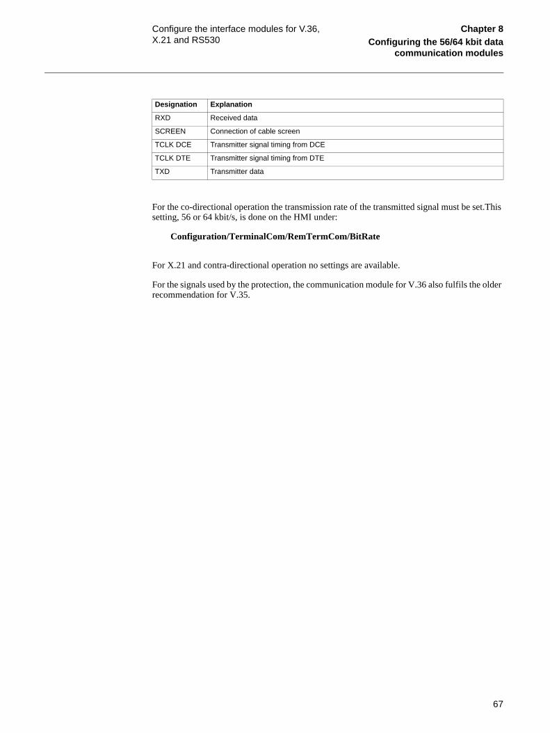
67
Configure the interface modules for V.36, X.21 and RS530
Chapter 8Configuring the 56/64 kbit data
communication modules
For the co-directional operation the transmission rate of the transmitted signal must be set.This setting, 56 or 64 kbit/s, is done on the HMI under:
Configuration/TerminalCom/RemTermCom/BitRate
For X.21 and contra-directional operation no settings are available.
For the signals used by the protection, the communication module for V.36 also fulfils the older recommendation for V.35.
RXD Received data
SCREEN Connection of cable screen
TCLK DCE Transmitter signal timing from DCE
TCLK DTE Transmitter signal timing from DTE
TXD Transmitter data
Designation Explanation

68
Configuring the interface modules for G.703 co-directional
Chapter 8Configuring the 56/64 kbit data
communication modules
6 Configuring the interface modules for G.703 co-directionalNo setting is available for the G.703 modem on the HMI. There are however some settings that can be made on a DIP-switch located behind the cover around the line connector at the back of the terminal according to figure 20. After the connector has been disconnected, if attached, the cover plate can be removed just by pulling at the middle of the cover plate. No settings are lo-cated on the circuit board.
Only switch 1 is used on the DIP-switch. In the ON position, transmission timing is generated internally in the modem. In the OFF position, transmission timing is generated by the received G.703 signal. Normally the OFF position shall be used when the terminal is connected to a mul-tiplexer or other communication equipment.If used in back to back operation switch 1 is set in ON position at one end and in OFF position at the other end. The rest of the switches shall be set to OFF.
There are also LEDs for supervision of the communication channel that can be seen when the cover around the fibre optic connectors is removed. These LED’s are located below the DIP-switch. The function of the LED’s isexplained in table 9.
Figure 20: G.703 modem, indications and settings
Table 9: Indications
A Line connector
B Cover plate
LED Explanation
TD Transmitted data
RD Received data
xx01000137.vsd
B
12345
A
On1234
TXDRXD

69
Fault tracing Chapter 8Configuring the 56/64 kbit data
communication modules
7 Fault tracingProcedure1. Check that the settings are correct.
2. Check that the optical budget is correct.
3. COMFAIL occurs for the following reasons:
The COMFAIL signal will be triggered when there is a problem in the communication link be-tween the two terminals, depending on type of 56/64 modem. Also, normal actions such as a change of setting, switch off of remote terminal during maintenance etc., can cause COMFAIL.
7.0.1 Comfail function
Figure 21: Comfail triggering.
The 200 ms alarm dropout delay is, for example, required as hysteresis for terminals with reserve overcurrent, REL 551 or distance reserve function REL 561, if the differential function is blocked by communication delays and interruptions etc.
The communication failure signal, COMFAIL, depends on the following internal signals (vari-ables) in each terminal for REx 5xx. Table 10 shows a summary with additional explanations below.
Drop-out delay; t = 200ms
COMFAIL triggering according to table
COMFAIL t
en03000125.vsd

70
Fault tracing Chapter 8Configuring the 56/64 kbit data
communication modules
Table 10: Summary
7.0.2 Explanation of contents in column 2 of table 421. Transmit errors are due to that the terminal cannot send messages via the tele-
communication channel (PCM). The line differential function initiates the send-ing of one message every 5 ms. If this command can not be executed for 10 consecutive times (= 10 x 5 ms) due to blocked, missing or unsynchronized com-munication channel, COMFAIL is triggered. For non-consecutive interruptions, an integration algorithm is used that prolongs the COMFAIL triggering time.
2. Receive errors occur when no expected messages are received. The line differen-tial function expects to receive one message every 5 ms. If this does not occur 10 consecutive times (= 10x5 ms), COMFAIL is triggered. For non-consecutive in-terruptions, an integration algorithm is used that prolongs the COMFAIL trigger-ing time.
No. COMFAIL triggering COMFAIL trigger-ing time (Drop-out delay 200 ms)
Remark
1 Transmit error ≥ 50 ms Messages can not be sent
2 Receive error ≥ 100 ms No valid messages received
3 Block differential protection 0 ms Block of the differential protection due to set-ting changes etc.
4 Remote terminal COMFAIL 0 ms COMFAIL from the remote terminal. For error no 1, 2, 3, and no 5, 6, 7, 8, 9, 10 the COM-FAIL is sent in the second consecutive mes-sage (within 10 ms)
5 Time synchronization error ≥ 2 s Problems in the synchronization of internal differential clock in the differential protection. The clock refers to the synchronized counters 0-39999 μs in each terminal. The clock is independent of the real time clock in the ter-minal.
6 Differential clock drift > 0 ms Unacceptable drift of the internal differential clock in the slave terminal compared to the internal differential clock in the master termi-nal (slave- master -slave)
7 Communication channel loop delay - instantaneous
0 ms Checks if the loop time (slave - master -slave) in the differential communication channel 31 ms
8 Communication channel loop delay - time delayed
≥ 2 s Checks if the loop time (local - remote- local) in the differential communication channel 24 ms
9 Abnormal clock deviation 0 ms Internal differential clock deviation (slave- master - slave)
10 Data flow
Only in version *2.3
0 ms Long time between attempts to send mes-sages and adjustment of the real time termi-nal clock . The terminal clock is the real time clock in the terminal for time tagging of events etc.

71
Fault tracing Chapter 8Configuring the 56/64 kbit data
communication modules
3. Block differential protection. Block of differential protection occurs during change of settings or setting group.
4. Remote terminal COMFAIL. For error No 1, 2, 3 and No 5, 6, 7, 8, 9, 10 the COMFAIL is sent in the second consecutive message (within 10 ms). Thus, some short interruptions can be recorded only in one terminal. The communication channel must be in operation to be able to receive this signal.
5. Time synchronization error refers to synchronization check and is only per-formed by the terminal set as Slave for the internal differential clocks synchroni-zation. If 50 time synchronization messages (included with every 8 line differential function message) are not correctly received (= 8 x 5 ms x 50 = 2000 ms), COMFAIL will be triggered. If more than 750 synchronization messages are not correctly received, a re-synchronization of the internal differential clock will be made. For non-consecutive interruptions, an integration algorithm prolongs the COMFAIL triggering time.
6. Differential Clock drift refers to a difference > 50 ms between the internal differ-ential clocks in the differential protection in the terminal set as Slave and the one set as Master for synchronization of the internal differential clock. The COM-FAIL triggering time depends on a number of factors from a drift compensation algorithm. This check is normally not activated unless the communication chan-nel has been lost for a long time.
7. Communication channel loop delay-instantaneous is checked every 40 ms (at each synchronization message). If the communication channel loop (Slave-Mas-ter-Slave) delay is more than 31ms for one message, COMFAIL is triggered in-stantaneously. This check is done in the terminal set as Slave for the internal differential clock by a comparison with the real time clock in the terminal at send-ing and receiving of a looped message.
8. Communication channel loop delay-time delayed checks if the communication channel delay for transmitted and received signal is >24 ms (Local-Remote-Lo-cal). The check is performed every 40 ms (at each synchronization message) by comparing the real time clock time at sending and receiving of a looped message. COMFAIL is triggered after 50 consecutive messages with excessive loop time. COMFAIL triggering time = 2000 ms (= 50x40 ms). For non-consecutive mes-sages with excessive loop time, an integration algorithm is used that prolongs the COMFAIL triggering.
9. Abnormal clock deviation checks if the synchronization in the Slave of the inter-nal differential clocks in the differential protection have an abnormal deviation, (Slave-Master–Slave). COMFAIL is triggered instantaneously, but will probably only occur after long interruptions in the communication channel. However, the start or re synchronization procedure can also activate COMFAIL due to this function.
10. Data flow checks if the time between initiations of the sending messages from the line differential function is longer than 20 ms, using the real time clock for the check. This check will also trigger the COMFAIL if the external time synchroni-zation of the real time clock by minute pulse or SPA/LON from Station Clock or GPS, adjusts the terminal clock forward > 15 ms. The COMFAIL triggering is instantaneous. The channel interruption measurements for short, medium and long interruptions, presented on the HMI are based on measurements of timing from the real time clock which are made independently in each terminal. These measurements are also independent from the internal differential clock. The mea-

72
Fault tracing Chapter 8Configuring the 56/64 kbit data
communication modules
surements presented on the front HMI are not connected to COMFAIL or by in-dications of channel delay exceeding 12 ms, since the delay is not a channel interrupt, the channel is still working.
73
Configuring the transceiver 21-15xx Chapter 8Configuring the 56/64 kbit data
communication modules
8 Configuring the transceiver 21-15xxFollow the instructions, for setting of jumpers, given in the document delivered with the trans-ceiver.
Here follow some recommendations on settings and connections when operating together with protection systems from ABB. In the following the transceiver is regarded as a DTE (although it is actually designed as a DCE) and is supposed to be connected to communication equipment that acts as a DCE.
For synchronous communication a DCE always has to output timing signals (TC and RC) and one input timing signal (TTC). For the DTE the opposite is valid. All clocks in a synchronous network have the same timing and provided the phase is set correctly they also have the same phase. This means that only one clock signal has to be used between the transceiver and the com-munication as shown in the cases below.

74
Co-directional operation Chapter 8Configuring the 56/64 kbit data
communication modules
9 Co-directional operationThe connection is made according to table 11.
Table 11: Connections
Figure 22 shows the connection. If needed for proper operation of the communication equipment a connection can be made between the RC and TC. Both TD and RD are controlled from TTC.
Figure 22: Connection between transceiver and communication equipment
The transceiver is set according to table 12.
Transceiver
Pin No.
V.35 V.36 Comm. eq.
Signal No A B A B Signal No Direction
TD 103 P S 4 22 RD 104 Comm. eq. -> Transceiver
RD 104 R T 6 24 TD 103 Transceiver -> Comm. eq.
TTC 113 U W 17 35 RC 115 Comm. eq. -> Transceiver
Tranceiver Communicationequipment
RD(A)RD(B)
TD(A)TD(B)
RC(A)RC(B)
TC(A)TC(B)
TD(A)TD(B)
RD(A)RD(B)
TTC(A)TTC(B)
en01000190.vsd

75
Co-directional operation Chapter 8Configuring the 56/64 kbit data
communication modules
Table 12: Settings
Switch, jumper Setting Gives
S1 Middle position V.35
S1 Bottom position V.36
S2 9 64 kbit/s
S3 Middle position External clock
S4 Has no influence on operation ---

76
Contra-directional operation Chapter 8Configuring the 56/64 kbit data
communication modules
10 Contra-directional operationConnected according to table 13.
Table 13: Connections
Figure 23 shows the connection. In this case the connection to TTC can be made either from RC or TC but not from both. Both TD and RD are controlled from TTC.
Figure 23: Connection between transceiver and communication equipment
Setting of transceiver is done according to table 14.
Transceiver
Pin No.
V.35 V.36 Comm. eq.
Signal No A B A B Signal No Direction
TD 103 P S 4 22 RD 104 Comm. eq -> Transceiver
RD 104 R T 6 24 TD 103 Transceiver -> Comm. eq.
TTC 113 U W 17 35 1) 1) Comm. eq. -> Transceiver1) Either RC - 115 or TC - 114 can be used.
where:
1 is the selection between either RC or TC
Tranceiver Communicationequipment
RD(A)RD(B)
TD(A)TD(B)
RC(A)RC(B)
TC(A)TC(B)
TD(A)TD(B)
RD(A)RD(B)
TTC(A)TTC(B)
en01000191.vsd
1)
1)

77
Contra-directional operation Chapter 8Configuring the 56/64 kbit data
communication modules
Table 14: Settings
Switch, jumper Setting Gives
S1 Middle position V.35
S1 Bottom position V.36
S2 9 64 kbit/s
S3 Middle position External clock
S4 Has no influence on operation ---

78
Configuring the transceiver 21-16xx Chapter 8Configuring the 56/64 kbit data
communication modules
11 Configuring the transceiver 21-16xxFor setting jumpers, follow the instructions in the document delivered with the transceiver.
Here follow some recommendations on settings and connections when using protection systems from ABB. In the following, the transceiver is regarded as a DTE and is supposed to be connect-ed to communication equipment that acts as a DCE.
11.1 X.21 operationThe connection is made according to table 15.
Table 15: Connections
Figure 24 shows the connection.
Figure 24: Connection between transceiver and communication equipment
Set transceiver according to table 16.
Transceiver Comm. eq.
Pin No.
Signal A B Signal Direction
T 2 9 T Comm. eq -> Transceiver
R 4 11 R Transceiver -> Comm. eq.
S 6 13 S Comm. eq. -> Transceiver
Tranceiver Communicationequipment
T(A)T(B)
R(A)R(B)
S(A)S(B)
T(A)T(B)
R(A)R(B)
S(A)S(B)
en01000192.vsd

79
Configuring the transceiver 21-16xx Chapter 8Configuring the 56/64 kbit data
communication modules
Table 16: Settings
11.2 G.703 co-directional operationConnect according to table 17.
Table 17: Connections
If a screen is available in the cable it is connected to Protection Ground (pin 9 on the transceiver) at one or both ends.
Figure 25 shows the connection. Note that the signal directions are according to DCE operation for both transceiver and communication equipment.
Figure 25: Connection between Transceiver and Communication equipment
Set transceiver according to table 18.
Switch, jumper Setting Gives
S2, S3, S4, S15, S16 Jumpers downwards DTE
S6 Second position from bottom X.21
S11 9 64 kbit/s
S14 Jumper at middle position External clock
S13 Has no influence on operation ---
Transceiver Comm. eq.
Signal Pin1) Signal Direction
TX 1/2 RX Comm. eq -> Transceiver
RX 3/4 TX Transceiver -> Comm. eq.1) RJ-45 connector. Numbered from left the connection points will bet this number
en01000193.vsd
Tranceiver Communicationequipment
RX(A)RX(B)
TX(A)TX(B)
TX(A)TX(B)
RX(A)RX(B)

80
Configuring the transceiver 21-16xx Chapter 8Configuring the 56/64 kbit data
communication modules
Table 18: Settings
Switch, jumper Setting
S5 G.703 co - con, balanced Nx64 kbps
S6 Co-directional
S7 Has no influence on operation
S8 Has no influence on operation
S9 Has no influence on operation
S11 9 (64 kbit/s)
S14 timing source External clock
S14 sync No jumper
S13 Has no influence on operation

81
About this chapter Chapter 9Setting and configuring the terminal
Chapter 9 Setting and configuring the terminal
About this chapterThis chapter describes how to set the terminal, either through a PC or the local HMI, and down-load a configuration to the terminal in order to make commissioning possible.
The chapter does not contain instructions on how to create a configuration or calculate settings. Please consult the application manual for further information about how to calculate settings.

82
Overview Chapter 9Setting and configuring the terminal
1 OverviewThe customer specific values for each setting parameter and a configuration file has to be avail-able before the terminal can be set and configured, if the terminal is not delivered with a config-uration.
Use the CAP 531 configuration tool to verify if the terminal has the expected configuration. A new configuration is performed with the CAP tool. The binary outputs can be selected from a signal list where the signals are grouped under their function names. It is also possible to specify a user-defined name for each input and output signal.
The configuration can be downloaded through the front connector on the local HMI or via the rear SPA port.
Each function included in the terminal has several setting parameters which have to be set in or-der to make the terminal behave as intended. A default value is provided for each parameter from factory. A setting file can be prepared using the parameter setting tool (PST), which is available in the CAP 540 package.
All settings can be:
• Entered manually through the local HMI.• Downloaded from a PC, either locally or remotely using SMS/SCS. Front or rear
port communication has to be established before the settings can be downloaded.
Note!Be sure to configure the functional input HMI--BLOCKSET to only one of the available binary inputs before setting the parameter SettingRestrict to Block in the local HMI.

83
Entering settings through the local HMI Chapter 9Setting and configuring the terminal
2 Entering settings through the local HMIEach of the included functions in the terminal has to be set and this can be performed through the local HMI. The user must browse to the desired function and enter the appropriate value. The parameters for each function can be found in the local HMI. See the technical reference manual for a complete list of setting parameters for each function. Some of the included functions may not be used. In this case the user can set the parameter “Operation” to “Off” to disable the func-tion.
Some settings can only be set through the local HMI, such as the setting access, the slave number and baud rate when communicating with a PC software. The setting access can be blocked by the binary input signal HMI--BLOCKSET. When this signal is active the user can still read all information, including the setting values.
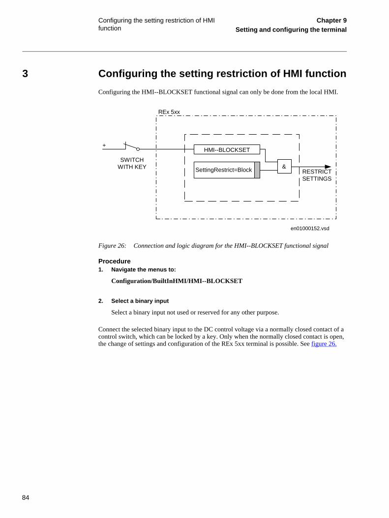
84
Configuring the setting restriction of HMI function
Chapter 9Setting and configuring the terminal
3 Configuring the setting restriction of HMI functionConfiguring the HMI--BLOCKSET functional signal can only be done from the local HMI.
Figure 26: Connection and logic diagram for the HMI--BLOCKSET functional signal
Procedure1. Navigate the menus to:
Configuration/BuiltInHMI/HMI--BLOCKSET
2. Select a binary input
Select a binary input not used or reserved for any other purpose.
Connect the selected binary input to the DC control voltage via a normally closed contact of a control switch, which can be locked by a key. Only when the normally closed contact is open, the change of settings and configuration of the REx 5xx terminal is possible. See figure 26.
SettingRestrict=Block RESTRICTSETTINGS
HMI--BLOCKSET
&SWITCH
WITH KEY
+
REx 5xx
en01000152.vsd

85
Activating the restriction of setting Chapter 9Setting and configuring the terminal
4 Activating the restriction of setting
4.1 Local HMIActivating the restriction of setting via local HMI can only be done from the local HMI.
Procedure1. Navigate the menus to:
Configuration/BuiltInHMI/SettingRestrict
2. Set SettingRestrict = Block.
4.2 Serial communication, change of active groupActivating the restriction of setting, or change of active group via the rear communication port, can only be done from the local HMI.
Procedure1. Navigate the menus to:
Configuration/TerminalCom/SPACom/Rear/ActGrpRestrict
2. Set ActGrpRestrict = Block
4.3 Serial communication, settingActivating the restriction of setting or change of active group, can only be done from the local HMI.
Procedure1. Navigate the menus to:
Configuration/TerminalCom/SPACom/Rear/SettingRestrict
2. Set SettingRestrict = Block
Note!The HMI--BLOCKSET functional input must be configured to the selected binary input before setting the setting restriction function in operation. Carefully read the instructions.

86
Downloading settings and configuration from a PC
Chapter 9Setting and configuring the terminal
5 Downloading settings and configuration from a PC
5.1 Establishing front port communicationWhen a PC is used to download settings and configuration, you need the terminal toolbox CAP 540 (including CAP 531 and PST).
A special cable is needed when connecting a PC to the front of the REx 5xx terminal. This cable can be ordered from ABB. It must be plugged into the optical contact on the left side of the local HMI. The other end of the cable shall be plugged directly into the COM-port on the PC. The cable includes an optical contact, an opto/electrical converter and an electrical cable with a stan-dard 9-pole D-sub contact. This ensures a disturbance-free and safe communication with the ter-minal.
When communicating from a PC, the slave number and baud rate (communication speed) set-tings must be equal in the PC-program and in the REx 5xx terminal.
Procedure1. Plug the cable to the optical contact on the local HMI.
2. Plug the other end of the cable to the COM port of the PC.
3. Set the slave number and baud rate in the terminal.
The slave number and baud rate settings in the REx 5xx terminal is done on the local HMI at:
Configuration/TerminalCom/SPACom/Front
4. Set the slave number and baud rate in the PC-program.
The slave number and baud rate must be the same as in the terminal. See the CAP 540 manual.
5.2 Establishing rear port communicationSettings can be performed via any of the optical ports at the rear of the REx 5xx terminal. When a PC is connected to the SMS system, the CAP 540 and the PST softwares are used. Settings can also be done via the SCS system, based on MicroLIBRARY.
5.2.1 Using the SPA/IEC rear portFor all settings and configuration via the SPA communication bus, the SPA/IEC 60870-5-103 port on the rear, it is necessary to first deactivate the restriction for settings. Otherwise, no setting is allowed. This setting only applies for the SPA/IEC 60870-5-103 port during SPA bus com-munication. The parameter can only be set on the local HMI, and is located at:
Configuration/TerminalCom/SPACom/Rear/SettingRestrict
It is also possible to permit changes between active setting groups with ActGrpRestrict in the same menu section.

87
Downloading settings and configuration from a PC
Chapter 9Setting and configuring the terminal
Selecting the protocols for the rear ports To define the protocols to be used, a setting is done on the local HMI under the menu:
Configuration/TerminalCom/SPA-IEC-LON
When the protocols have been selected the terminal will automatically restart.
When communicating with SMS or SCS with the SPA or IEC 60870-5-103 protocol the slave number and baud rate (communication speed) settings must be equal in the PC-program and in the REx 5xx terminal.
Using the SPA rear portThe slave number and baud rate settings of the rear SPA port on the REx 5xx terminal, for SPA bus communication, is done on the local HMI at:
Configuration/TerminalCom/SPACom/Rear
Using IEC 870-5-103 rear portThe slave number and baud rate settings of the rear IEC 60870-5-103 port on the REx 5xx ter-minal, for IEC 870-5-103 bus communication, is done on the local HMI at:
Configuration/TerminalCom/IECCom/Communication
5.2.2 Using LON rear portThe LON port is not affected by eventual restricted settings valid for the SPA/IEC port. When communicating via the LON port, the settings are done with the LNT, LON Network Tool. The settings are shown on the local HMI at:
Configuration/TerminalCom/LON Com
From this menu, it is also possible to send the “ServicePinMsg” to the LNT.
5.3 Downloading the configuration and setting filesWhen downloading a configuration to the REx 5xx terminal with the CAP 531 configuration tool, the terminal is automatically set in configuration mode. When the terminal is set in config-uration mode, all functions are blocked. The red LED on the terminal flashes, and the green LED is lit while the terminal is in the configuration mode.
When the configuration is downloaded and completed, the terminal is automatically set into nor-mal mode. For further instructions please refer to the users manuals for CAP 540 and PST.

88
Downloading settings and configuration from a PC
Chapter 9Setting and configuring the terminal

89
About this chapter Chapter 10Requirement of trig condition for
disturbance report
Chapter 10 Requirement of trig condition for disturbance report
About this chapterThis chapter describes how to override the limitation on the storage capacity of the flash mem-ory.

90
Requirement of trig condition for disturbance report
Chapter 10Requirement of trig condition for
disturbance report
1 Requirement of trig condition for disturbance reportDisturbance reports, setting and internal events in REx 5xx are stored in a non volatile flash memory. Flash memories are used in many embedded solutions for storing information due to high reliability, high storage capacity, short storage time and small size.
In REx 5xx there is a potential failure problem, caused by too many write operations to the flash memory.
Our experience shows that after storing more than fifty thousand disturbances, settings or inter-nal events the flash memory exceeds its storing capacity and the component is finally defected.
When the failure occurs there is no risk of unwanted operation of the protection terminal due to the self-supervision function that detects the failure. The terminal will give a signal for internal fail and go into blocking mode.
The above limitation on the storage capacity of the flash memory gives the following recom-mendation for the disturbance report trig condition:
• Cyclic trig condition more often then once/day not recommended.• Minute pulse input is not used as a trig condition.• Total number of stored disturbance reports shall not exceed fifty thousand.

91
About this chapter Chapter 11Establishing connection and
verifying theSPA/IEC-communication
Chapter 11 Establishing connection and verifying the SPA/IEC-communication
About this chapterThis chapter contains instructions on how to establish connection and verify that the SPA/IEC-communication operates as intended, when the terminal is connected to a monitoring or control system via the rear SPA/IEC port.

92
Entering settings Chapter 11Establishing connection and
verifying the
1 Entering settingsIf the terminal is connected to a monitoring or control system via any of the rear SPA and/or IEC ports, the applicable selection of protocols for the rear ports must be made.
1.1 Entering SPA settingsWhen using the SPA protocol, the rear SPA/IEC port must be set for SPA use.
The SPA/IEC port is located at terminal X13 on the rear side of the terminal. Three types of interfaces can be used:
• for plastic fibres with connector type HFBR• for glass fibres with connectors type ST• for galvanic RS485
Procedure1. Set the operation of the rear SPA/IEC port to “SPA”.
The operation of the rear SPA/IEC port can be found on the local HMI at:
Configuration/TerminalCom/SPA-IEC-LON
When the setting is entered the terminal will automatically restart. After the restart the SPA/IEC port operates as a SPA port.
2. Set the slave number and baud rate for the rear SPA port
The slave number and baud rate can be found on the local HMI at:
Configuration/TerminalCom/SPACom/Rear
Set the same slave number and baud rate as set in the SMS system for the terminal.
1.2 Entering IEC settingsWhen using the IEC protocol, one of the rear ports must be set for IEC use. The selected port can be located at terminal X13 or terminal X15 on the rear side of the terminal. Valid interface depends on selected port.Three types of interfaces can be used:
• for plastic fibres with connector type HFBR• for glass fibres with connectors type ST• for galvanic RS485
Procedure1. Set the operation of one of the rear ports to “IEC”.
The operation of the rear ports can be found on the local HMI at:

93
Entering settings Chapter 11Establishing connection and
verifying theSPA/IEC-communication
Configuration/TerminalCom/SPA-IEC-LON
When the setting is entered the terminal will automatically restart. After the restart the selected IEC port operates as a IEC port.
2. Set the slave number and baud rate for the rear IEC port
The slave number and baud rate can be found on the local HMI at:
Configuration/TerminalCom/IECCom/Communication
Set the same slave number and baud rate as set in the IEC master system for the terminal.
3. Set the main function type of the terminal.
The main function type can be found on the local HMI at:
Configuration/TerminalCom/IECCom/FunctionType
The main function type can be set to values from 1 to 255 according to the standard. The value zero is default and corresponds to not used. Ex-amples of values that can be used are:
Table 19: Main function type examples
If the setting “OpFnType” is set to “ON” then the set value for function type will be used for all event blocks and the disturbance recorder, other-wise the setting on each event block and the disturbance recorder will de-cide the function type of that function block.
Value Function type according to IEC 60870-5-103
128 Distance protection
160 Overcurrent protection
192 Line differential protection

94
Verifying the communication Chapter 11Establishing connection and
verifying the
2 Verifying the communicationTo verify that the rear communication with the SMS/SCS system is working, there are some dif-ferent methods. Choose one of the following.
2.1 Verifying SPA communication
Procedure1. Use a SPA-emulator and send “RF” to the terminal. The answer from
the terminal should be “REx500 25”.
2. Generate one binary event by activating a function which is config-ured to an event block where the used input is set to generate events on SPA. The configuration must be made with the CAP5xx software. Verify that the event is presented in the SMS/SCS system.
During the following tests of the different functions in the terminal, verify that the events and indications in the SMS/SCS system are as expected.
2.2 Verifying IEC communicationTo verify that the IEC communication with the IEC master system is working, there are some different methods. Choose one of the following.
Procedure1. Check that the master system time-out for response from the termi-
nal, for example after a setting change, is > 40 seconds.
2. Use a protocol analyzer and record the communication between the terminal and the IEC master. Check in the protocol analyzer’s log that the terminal answers the master messages.
3. Generate one binary event by activating a function which is config-ured to an event block where the used input is set to generate events on IEC. The configuration must be made with the CAP5xx software. Verify that the event is presented in the IEC master system.
During the following tests of the different functions in the terminal, verify that the events and indications in the IEC master system are as expected.

95
Optical budget calculation for serial communication with SPA/IEC
Chapter 11Establishing connection and
verifying theSPA/IEC-communication
3 Optical budget calculation for serial communication with SPA/IECTable 20: Example
Distance 1 km
Glass
Distance 25 m
Plastic
Maximum attenuation for REx 5xx - 11 dB - 7 dB
4 dB/km multi mode: 820 nm - 62.5/125 um 4 dB -
0.16 dB/m plastic: 620 nm - 1mm - 4 dB
Margins for installation, aging etc. 5 dB 1 dB
Losses in connection box, two contacts (0.7 dB/contact) 1.4 dB -
Losses in connection box, two contacts (1 dB/contact) - 2 dB
Margin for repair splices (0.5 dB/splice) 0.5 dB -
Maximum total attenuation 11 dB 7 dB

96
Optical budget calculation for serial communication with SPA/IEC
Chapter 11Establishing connection and
verifying the

97
About this chapter Chapter 12Establishing connection and
verifying the LON communication
Chapter 12 Establishing connection and verifying the LON communication
About this chapterThis chapter referes to another document.

98
Reference Chapter 12Establishing connection and
verifying the LON communication
1 ReferenceWe refere to document: LNT 505 Operator’s Manual 1MRS751706-MUM, Issued: 31.10.99, Program rev: 1.1.1 Doc. version: B.
1.1 Verification of the optical budget
1.1.1 Optical budget calculation for serial communication with LON Table 21: Example
Distance 1 km
Glass
Distance 20 m
Plastic
Maximum attenuation for REx 5xx -11 dB - 7 dB
4 dB/km multi mode: 820 nm - 62.5/125 um 4 dB -
0.2 dB/m plastic: 620 nm - 1mm - 4 dB
Margins for installation, aging etc. 5 dB 1 dB
Losses in connection box, two contacts (0.7 dB/contact) 1.4 dB -
Losses in connection box, two contacts (1dB/contact) - 2 dB
Margin for repair splices (0.5 dB/splice) 0.5 dB -
Maximum total attenuation 11 dB 7 dB

99
About this chapter Chapter 13Verifying settings by secondary
injection
Chapter 13 Verifying settings by secondary injection
About this chapterThis chapter describes how to verify that the protection functions operates correctly according to the settings. Only the tested function should be in operation.

100
Overview Chapter 13Verifying settings by secondary
injection
1 OverviewRequired tools for testing of a terminal:
• Calculated settings• Configuration diagram• Terminal diagram• Technical reference manual• Three-phase test equipment
The terminal has to be set and configured before the testing can start.
The terminal diagram, available in the Technical reference manual, is a general diagram for the terminal. But note that the same diagram is not always applicable for each specific delivery (es-pecially for the configuration of all the binary inputs and outputs). It is for this reason necessary to check before testing that the available terminal diagram corresponds to the terminal.
The Technical reference manual contains application and functionality summaries, function blocks, logic diagrams, input and output signals, setting parameters and technical data sorted per function.
The test equipment should be able to provide a three-phase supply of voltages and currents. The magnitude of voltage and current as well as the phase angle between voltage and current must be variable. The voltages and currents from the test equipment must be obtained from the same source and they must have a very small harmonic contents. If the test equipment cannot indicate the phase angle, a separate phase-angle meter is necessary.
Prepare the terminal for test before testing a particular function. Consider the logic diagram of the tested protection function when performing the test. All included functions in the terminal are tested according to the corresponding test instructions in this chapter. The functions can be tested in any order according to user preferences and the test instructions are therefor presented in alphabetical order. Only the functions that are used (Operation is set to On) should be tested.
The response from a test can be viewed in different ways:
• Binary outputs signals• Service values in the local HMI (logical signal or phasors)• A PC with CAP (configuration software) in debug mode
All used setting groups should be tested.
Note! This terminal is designed for a maximum continuous current of four times the rated current.

101
Overview Chapter 13Verifying settings by secondary
injection
Note!Please observe the measuring accuracy of the terminal, the test equipment and the angular ac-curacy for both of them.
Note!Please consider the configured logic from the function block to the output contacts when mea-suring the operate time.

102
Preparing for test Chapter 13Verifying settings by secondary
injection
2 Preparing for test
2.1 OverviewThis section describes how to prepare the terminal in order to verify settings.
The preparation starts with making the connections to the test switch if included. This means connecting the test equipment according to a valid terminal diagram for the specific REx 5xx terminal. The terminal can then be set in test mode in order to facilitate the test of individual functions and prevent unwanted operation from functions other than the tested. The test switch should then be connected to the terminal. The user could also verify the connection and that the analog inputs signals are measured correctly by injecting currents and voltages as required by the specific REx 5xx terminal. The tested function should then be released. The disturbance re-port settings could be checked to ensure that correct indications are given. The user could also identify the function to test in the technical reference manual to retrieve signals and parameters names etc.
2.2 Preparing the connection to the test equipmentThe REx 5xx terminal can be equipped with a test switch of type RTXP 24. The test switch and its associated test plug handle (RTXH 24) are a part of the COMBITEST system which gives a secure and convenient testing of the terminal.
When the test-plug handle is inserted into the test switch, preparations for testing are automati-cally carried out in the proper sequence (i.e. blocking of tripping circuits, short circuiting of CT’s, opening of voltage circuits, making relay terminals available for secondary injection). Terminals 1 and 12 of the test switch are not disconnected as they are used for dc supply of the protection terminal.
The test-plug handle leads may be connected to any type of test equipment or instrument. When a number of protection terminals of the same type are tested, the test-plug handle need be moved only from the test switch of one protection terminal to the test switch of the other, without alter-ing previously made connections.
To prevent unwanted tripping when the handle is withdrawn, latches on the handle secure it in the half withdrawn position. In this position, all voltages and currents are restored to the protec-tion terminal and any reenergizing transients are given a chance to decay before the trip circuits are restored. When the latches are released, the handle can be completely withdrawn form the test switch, restoring the trip circuits to the protection terminal.
If a test switch is not used necessary actions need to be taken according to circuit diagram.
103
Preparing for test Chapter 13Verifying settings by secondary
injection
2.3 Setting the terminal in test modeThe terminal can be set in test mode before test. This means that all included functions can be blocked or released as decided during the test. In this way, it is possible to test slower back-up measuring functions without the interference of faster measuring functions. Test mode is indi-cated when the yellow LED is flashing.
Procedure1. Browse to the ‘Operation’ menu and press ‘E’.
The Operation menu is located in the local HMI under:
Test/TestMode/Operation
2. Choose ‘On’ and press ‘E’.
3. Press ‘C’ twice to exit the menu.
The dialog ‘Save testGroup?’ appears.
4. Choose ‘Yes’ and leave the menu.
The window repeatedly displays ‘Busy’ and after that the yellow LED starts flashing which indicates that the terminal is in test mode.
2.4 Connecting test equipment to the terminalBefore testing, connect the testing equipment according to the valid terminal diagram for each specific REx 5xx terminal. Pay special attention to the correct connection of the input and output current terminals, and to the connection of the residual current. Check that the input and output logical signals in the logic diagram for the tested function are configured to the corresponding binary inputs and outputs of the tested terminal.
Warning!Never disconnect a secondary connection of current transformer circuit without short-circuiting the transformer's secondary winding. Operating a current transformer with the secondary wind-ing open will cause a massive potential build-up that may damage the transformer and may cause injuries to humans.

104
Preparing for test Chapter 13Verifying settings by secondary
injection
Figure 27: Connection of the test set to the REx 5xx terminal.
2.5 Verifying the connection and the analog inputsThe user must verify that the connection and that the analog signals are measured correctly.
Procedure1. Compare the injected value with the measured value.
The phasor menu is located in the local-HMI under:
ServiceReport/Phasors/Primary and Secondary
Consider set ratio factors for CT’s and VT’s.
2. Compare the frequency reading with the set frequency and the direc-tion of the power with the injected power.
The frequency and active power are located in the local-HMI under:
ServiceReport/ServiceValues
3. Inject a unsymmetrical three-phase current and voltage at rated val-ue in two phases.
4. Compare the injected value with the measured value.
The phasor menu is located in the local-HMI under:
IL1IL2IL3NI
UL1UL2UL3UN
IL1IL2IL3
UL1
IN (I4,I5)
TRIP L1TRIP L2TRIP L3
REL
AY T
EST
SET
REx
5xx
en01000162.vsd
UL2UL3UNUN (U4,U5)

105
Preparing for test Chapter 13Verifying settings by secondary
injection
ServiceReport/Phasors/Primary and Secondary
2.6 Releasing the function(s) to be testedThe user can release the function(s) to be tested. This is done in order to set only the tested func-tion(s) in operation and prevent other functions from operating. The user can release the tested function(s) by setting the corresponding parameter under BlockFunctions to NO in the local HMI. When testing a function in this blocking feature, remember that not only the actual func-tion must be activated, but the whole sequence of interconnected functions (from measuring in-puts to binary output contacts), including logic and so on. Before starting a new test mode session the user should scroll through every function to ensure that only the function to be tested (and the interconnected ones) are set to NO. A function is also blocked if the BLOCK input sig-nal on the corresponding function block is active, which depends on the configuration. The user should therefore ensure that the logical status of the BLOCK input signal is equal to 0 for the tested function. The user could also individually block event blocks to ensure that no events are reported to remote station during the test.
Procedure1. Browse to the ‘BlockFunctions’ menu.
The BlockFunctions menu is located in the local HMI under:
Test/TestMode/BlockFunctions
2. Browse to the function that should be released.
Use the left and right arrow buttons. Press ‘E’ when the desired function has been found.
3. Select ‘No’.
4. Press ‘C’ twice to leave the menu.
The ‘Save TestGroup?’ dialog appears.
5. Choose ‘Yes’ leave the menu.
2.7 Checking the disturbance report settingsThe terminal must be set in testmode (Operation=ON) to activate the disturbance report settings.
The user can select how the disturbances are indicated on the local HMI during the test. The user can for example select if the disturbance summary should be stored, scrolled on the local HMI or if LED information should be stored. Scroll to the disturbance report settings which are locat-ed in the local HMI under:
Note!The function is blocked if the corresponding setting under the BlockFunctions menu remains on and the TEST-INPUT signal remains active. All functions that where blocked or released from previous test mode session are still valid when a new test mode session is entered.

106
Preparing for test Chapter 13Verifying settings by secondary
injection
Test/TestMode/DisturbReport
Table 22: Disturbance report settings
2.8 Identifying the function to test in the technical reference manualThe user can use the technical reference manual (TRM) to identify function blocks, logic dia-grams, input and output signals, setting parameters and technical data.
Operation DisturbSum-mary
Then the results are...
Off Off • Disturbances are not stored.• LED information is not displayed on the HMI and not stored.• No disturbance summary is scrolled on the HMI.
Off On • Disturbances are not stored.• LED information (yellow - start, red - trip) are displayed on the local
HMI but not stored in the terminal.• Disturbance summary is scrolled automatically on the local HMI for the
two latest recorded disturbances, until cleared.• The information is not stored in the terminal.
On On or Off • The disturbance report works as in normal mode.• Disturbances are stored. Data can be read from the local HMI, a
front-connected PC, or SMS.- LED information (yellow - start, red - trip) is stored.
• The disturbance summary is scrolled automatically on the local HMI for the two latest recorded disturbances, until cleared.
• All disturbance data that is stored during test mode remains in the ter-minal when changing back to normal mode.

107
Autorecloser (AR) Chapter 13Verifying settings by secondary
injection
3 Autorecloser (AR)The test can be divided into to parts; one to verify the internal logic and one to verify the co-op-eration with the protection system. This section deals with the first test.
Prepare the terminal for verification of settings as outlined in section 2 "Preparing for test" in this chapter.
The test is performed together with protection and trip functions. Figure 28 illustrates a recom-mended testing scenario, where the circuit breaker is simulated by an external bistable relay (BR), for example an RXMVB2 or an RXMVD. The following switches are needed:
• Switch close (SC)• Switch trip (ST)• Switch ready (SRY).
SC and ST can be push-buttons with spring return. If no bistable relay is available, replace it with two self-reset auxiliary relays and use self-holding connection.
Use a secondary injection relay test set to operate the protection function. It is possible to use the BR to control the injected analogue quantities so that the fault only appears when the BR is picked up—simulating a closed breaker position.
To make the arrangement more elaborate, include the simulation of the operation gear condition, AR01-CBREADY, for the sequences Close-Open (CO) and Open-Close-Open (OCO).
The AR01-CBREADY condition at the CO sequence type is usually low for a recharging time of 5-10 s after a closing operation. Then it is high. The example in figure 28 shows that it is sim-ulated with SRY, a manual switch.

108
Autorecloser (AR) Chapter 13Verifying settings by secondary
injection
Figure 28: Simulating breaker operation with two auxiliary relays.
3.1 Preparing
1. Check the settings of the autorecloser (AR) function.
The operation can be set at Stand-by (Off) in HMI tree:
Settings/Functions/Group n/AutoRecloser/AutoRecloser n
If any timer setting is changed so as to speed-up or facilitate the testing, they must be set to normal after the testing. A verification test has to be done afterwards.
2. Check that the functional input signal SYNC is set to TRUE if the in-ternal or external synchrocheck is not used.
3. Read and note the reclosing operate counters from the HMI tree:
Terminal
AR01 - CLOSE CB
Trip
AR01 - CB CLOSE
AR01 - CB READY
BR
SC
ST
SRY
To testset
+ -en02000446.vsd

109
Autorecloser (AR) Chapter 13Verifying settings by secondary
injection
ServiceReport/Functions/AutoRecloser/AutoRecloser n/Counters
4. Do the testing arrangements outlined above, for example, as in fig-ure 28.
5. The AR01-CBCLOSED breaker position, the commands Trip and Closing, AR01-CLOSECB, and other signals should preferably be ar-ranged for event recording provided with time measurements.
Otherwise, a separate timer or recorder can be used to check the AR open time and other timers.
3.2 Checking the AR functionality
1. Ensure that the voltage inputs to Synchro-check, when applied, give accepted conditions at open breaker (BR).
They can, for example, be Live busbar and Dead line.
2. Set the operation at On.
3. Make a BR pickup by a closing pulse, the SC-pulse.
4. Close SRY, Breaker ready and leave it closed.
5. Inject AC quantities to give a trip and start AR in phase L1.
Observe or record the BR operation. The BR relay should trip and re-close. After the closing operation, the SRY switch could be opened for about 5 s and then closed.
The AR open time and the operating sequence should be checked, for ex-ample, in the event recording.
Check the operate indications and the operate counters.
Should the operation not be as expected, the reason must be investigated. It could be due to an AR Off state or wrong program selection, or not ac-cepted synchro-check conditions.
6. Repeat procedure 5 for phase L2 and L3, two-phase and three-phase trips, transient, and permanent fault.
The signal sequence diagrams in the Technical reference manual can be of guidance for the checking.
3.3 Checking the reclosing conditionThe number of cases can be varied according to the application. Examples of selection cases are:

110
Autorecloser (AR) Chapter 13Verifying settings by secondary
injection
3.3.1 Checking the Inhibit signal
1. Check that the function is operative and that the breaker conditions are okay.
2. Apply an AR01-INHIBIT input signal and start the reclosing function.
3. Check that there is no reclosing.
3.3.2 Checking the closing onto a fault
1. Set the breaker simulating relay, BR, in position open.
2. Then close it with the SC switch and start the AR within one second.
3. Check that there is no reclosing.
3.3.3 Checking the breaker not ready
1. Close the BR breaker relay and see that everything except for AR01-CBREADY is in normal condition (SRY is open).
2. Start the AR function.
3. Check that there is no reclosing.
3.3.4 Checking the synchro-check condition (for three-phase reclosing cycle)
1. Check the function at non-acceptable voltage conditions.
2. Wait for the time out, >5 s.
3. Check that there is no reclosing.
3.3.5 Checking the operation Stand-by and Off
1. Check that no reclosing can occur with the function in Off state.
2. Check the operation in stand-by mode.
Depending on the program selection and the selected fault types that start and inhibit reclosing, a check of no unwanted reclosing can be made. For example, if only single-phase reclosing is selected, a test can verify that there is no reclosing after two-phase and three-phase trips.
111
Autorecloser (AR) Chapter 13Verifying settings by secondary
injection
3.4 Testing the multi-breaker arrangementIf a multi-breaker arrangement is used for the application and priorities are given for the master (high) and slave (low) terminals, test that correct operation takes place and that correct signals are issued. The signals WFMASTER, UNSUC, WAIT and INHIBIT should be involved.
3.5 Completing the testAfter the test, restore the equipment to normal or desired state. Especially check these items:
1. Check and record the counter contents (Reset if it is the user’s pref-erence).
The counters menu is located in the local HMI under:
ServiceReport/Functions/AutoRecloser/AutoRecloser n/Counters/Clear Counters
2. Reset the setting parameters as required.
3. Disconnect the test switch or disconnected links of connection ter-minals.
4. Reset indications and events.
The ClearDistRep menu is located in the local HMI under:
DisturbReport/ClearDistRep
Continue to test another function or complete the test by setting the test mode to off. Restore connections and settings to the original values, if they were changed for testing purpose.
112
Breaker failure protection (BFP) Chapter 13Verifying settings by secondary
injection
4 Breaker failure protection (BFP)Prepare the terminal for verification of settings as outlined in section 2 "Preparing for test" in this chapter.
Consider to release used start criteria. The trip is a pulse with a length of 150 ms. Fault condition: the current in a phase must exceed the set IP> as latest within the set t1 time after the START/STLN input is activated.
To verify the settings the following fault type should be tested:
• One for a phase-to-earth fault
The breaker-failure protection should be tested in co-operation with some other functions, and in particular with the protection and trip functions or via external start.
4.1 Verifying the settings
Procedure1. Apply the fault condition with a current below set IP>.
2. Repeat the fault condition and increase the current in step until trip appears.
3. Compare the result with the set IP>.
Note: If no I> check is set only back-up trip operate at set IP>.
4.2 Verifying the retrip settingChoose one of the test cases in 4.2 "Verifying the retrip setting" according to valid setting.
4.2.1 Checking the retrip function with retrip set to off
Procedure1. Set RetripType = Retrip Off.
2. Apply the fault condition with current over the set value.
3. Verify that retrip in phase L1 is not achieved.
4.2.2 Checking the retrip function with current check
Procedure1. Set RetripType = I> check.
2. Apply the fault condition with current over the set value.
3. Verify that retrip is achieved after t1 that back-up trip is achieved af-ter t2.

113
Breaker failure protection (BFP) Chapter 13Verifying settings by secondary
injection
4.2.3 Checking the retrip function without current check
Procedure1. Set RetripType = No I> check.
2. Apply the fault condition with current below the set value.
3. Verify that retrip is achieved after t1.
4. Apply the fault condition with current over the set value.
5. Verify that back-up trip is achieved after t2.
4.3 Completing the testContinue to test another function or complete the test by setting the test mode to off. Restore connections and settings to the original values, if they were changed for testing purpose.
114
Broken conductor check (BRC) Chapter 13Verifying settings by secondary
injection
5 Broken conductor check (BRC)Prepare the terminal for verification of settings as outlined in section 2 "Preparing for test" in this chapter.
5.1 Measuring the operate and time limit of set values
Procedure1. Check that the input logical signal BRC-BLOCK is logical zero and
note on the local HMI that the BRC-TRIP logical signal is equal to the logical 0.
Values of the logical signals belonging to the broken conductor check function are available under menu tree:
ServiceReport/Functions/BrokenConduct/FuncOutputs
2. Quickly set the measured current (fault current) in one phase to about 110% of the setting (IP>) operating current, and switch off the current with the switch.
Observe the maximum permitted overloading of the current circuits in the terminal.
3. Switch on the fault current and measure the operating time of the BRC protection.
Use the BRC--TRIP signal from the configured binary output to stop the timer.
4. Compare the measured time with the set value t.
5. Activate the BRC--BLOCK binary input.
6. Switch on the fault current (110% of the setting) and wait longer than the set value t.
No BRC--TRIP signal should appear.
7. Switch off the fault current.
8. Quickly set the measured current (fault current) in same phase to about 90% of the setting operating current, and switch off the current with the switch.
9. Switch on the fault current and wait longer than the set value t.
No BRC--TRIP signal should appear.
10. Switch off the fault current.
11. Continue to test another function or complete the test by setting the test mode to off.

115
Communication channel test logic (CCHT) Chapter 13Verifying settings by secondary
injection
6 Communication channel test logic (CCHT)Prepare the terminal for verification of settings as outlined in section 2 "Preparing for test" in this chapter.
6.1 Testing the logic
1. Set all the timers according to the recommendations.
2. Activate the CCHT--CR binary input.
3. Measure the CCHT--CS binary output.
A pulse should appear “tCS”.
4. Activate the CCHT--START and wait longer than “tWait”.
The CCHT--ALARM should appear.
5. Activate the CCHT--RESET to reset the alarm.
6. When the communication channel is connected, activate the CCHT--START and wait for the signal to come back.
The CCHT--CHOK should appear.
7. Continue to test another function or complete the test by setting the test mode to off.

116
Current circuit supervision (CTSU) Chapter 13Verifying settings by secondary
injection
7 Current circuit supervision (CTSU)Prepare the terminal for verification of settings as outlined in section 2 "Preparing for test" in this chapter.
The current circuit supervision function is conveniently tested with the same 3-phase test set as used when testing the measuring functions in the REx 5xx.
Procedure1. Check the input circuits and the operate value of the IMinOp current
level detector by injecting current, one phase at a time.
2. Check the phase current blocking function for all three phases by in-jecting current, one phase at a time.
The output signals shall reset with a delay of 1 s when the current exceeds 1.5·I1b.
3. Inject a current 0.90·I1b to phase L1 and a current 0.15·I1b to the ref-erence current input (I5).
4. Decrease slowly the current to the reference current input and check that blocking is obtained when the current is about 0.10·I1b.
5. Continue to test another function or complete the test by setting the test mode to off.

117
Time delayed residual overcurrent protection (TEF)
Chapter 13Verifying settings by secondary
injection
8 Time delayed residual overcurrent protection (TEF)Prepare the terminal for verification of settings as outlined in section 2 "Preparing for test" in this chapter.
Normally, the test of the earth-fault overcurrent protection is made in conjunction with the test-ing of the distance protection functions, using the same multiphase test-set. Observe that the po-larising voltage is equal to -3Uo.
8.1 Checking the operate values of the current measuring elements
Procedure1. Set the logical input signals to logical 0 and note on the local HMI
that the TEF--TRIP and the TEF--TRSOTF signal is not activated (= logical 0).
Values of the logical signals belonging to the time delayed residual over-current protection are available under menu tree:
ServiceReport/Functions/EarthFault/TimeDelayEF
2. Set the polarising voltage to 2% of Ub and the phase angle between voltage and current to 65°, the current lagging the voltage.
3. Check that the operate current of the forward directional element is equal to the IN> Dir setting.
The IN> Dir function activates the TEF--STFW output.
4. Check with angles ϕ = 20° and 110° that the measuring element op-erates when 3I0 cos (65° - ϕ) >= IN> Dir.
5. Reverse the polarising voltage (ϕ = 180° + 65° = 245°) and check that the operate current of the reverse directional element is 0.6 · IN> Dir.
The function activates the TEF--STRV output.

118
Time delayed residual overcurrent protection (TEF)
Chapter 13Verifying settings by secondary
injection
Figure 29: Measuring characteristic of the directional element.
6. To activate the directional function, set Direction = Directional.
7. Set the polarising voltage to 2% of Ub and the phase angle between voltage and current to 65°.
8. Check the operate current of the IMin function.
The function activates the TEF--START output.
9. When independent time delay (definite) is selected, check the oper-ate time of the t1 timer by injecting a current two times the set IMin operate value.
When inverse time delay is selected, check the operate time at three points of the inverse characteristic. The formulas for operate time for dif-ferent types of inverse time delay curves are shown in table 23.
IN>Dir
IN Operation
Upol = -3U0
99000052.vsd
65°
ϕ

119
Time delayed residual overcurrent protection (TEF)
Chapter 13Verifying settings by secondary
injection
Table 23: Operate time formulas
Also check the tMin (minimum operate time) and IMin (minimum oper-ate current) functions.
10. Activate the TEF--BC input to check the function of the switch-on-to-fault logic.
11. Check that the TEF--TRSOTF output is activated with a 300 ms time delay when injecting a current two times the set IMin operate value in forward direction.
12. Set the phase angle of the polarising voltage to ϕ =245° and check that the directional current function and the switch-onto-fault logic gives no operation when the current is in the reverse direction.
13. Connect the rated DC voltage to the TEF--BLOCK configured binary input and switch on the fault current.
No TEF--TRIP nor TEF--START signal should appear.
14. Switch off the fault current.
15. Connect the rated DC voltage to the TEF--BLKTR configured binary input and switch on the fault current.
No TEF--TRIP nor TEF--TRSOTF should appear. But the output TEF--START shall be activated.
16. Continue to test another function or complete the test by setting the test mode to off.
Characteristics Operate time (s)
Normal inverse(Equation 1)
Very inverse(Equation 2)
Extremely inverse(Equation 3)
Logarithmic inverse(Equation 4)
Where:
I is a multiple of set current 3I0>
k is a time multiplying factor, settable in the range of 0.05 to 1.10
t 0.14I0.02 1–-------------------- k⋅=
t 13.5I 1–----------- k⋅=
t 80I2 1–------------- k⋅=
t 5.8 1.35 Iln⋅( )–=
120
Disturbance recorder (DR) Chapter 13Verifying settings by secondary
injection
9 Disturbance recorder (DR)Evaluation of the results from the disturbance recording function requires access to a worksta-tion either permanently connected to the terminal or temporarily connected to the serial port on the front. The CAP tool software package must be installed in the workstation.
Disturbance upload can be performed by the use of SMS 510, CAP 540 or by any third party tool with IEC 60870-5-103 protocol. Disturbance files can be analyzed by any tool reading Comtrade formatted disturbance files including REVAL and WinEve.
It could be useful to have a printer for hard copies. The behavior of the disturbance recording function can be checked when protective functions of the terminal are tested. When the terminal is set to operate in test mode, there is a separate setting for operation of the disturbance report, which also affects the disturbance recorder.
A manual trig can be started any time. This results in a snap-shot of the actual values of all re-corded channels.

121
Event counter (CN) Chapter 13Verifying settings by secondary
injection
10 Event counter (CN)The function can be tested by connecting a binary input to the counter under test and from out-side apply pulses to the counter. The speed of pulses must not exceed 10 per second. Normally the counter will be tested in connection with tests on the function that the counter is connected to, such as trip logic. When configured, test it together with the function which operates it. Trig the function and check that the counter has followed the number of operations.

122
Event function (EV) Chapter 13Verifying settings by secondary
injection
11 Event function (EV)During testing, the terminal can be set in test mode from the PST. The functionality of the event reporting during test mode is set from the PST as follows:
• Use event masks• Report no events• Report all events
In Test Mode, individual event blocks can be blocked from the PST.
Individually event blocks can also be blocked from the local HMI under the menu:
Test/TestMode/BlockEventFunc

123
Event recorder (ER) Chapter 13Verifying settings by secondary
injection
12 Event recorder (ER)During testing, the event recorder can be switched off if desired. This is found in the SMS or Substation Control System (SCS).

124
Instantaneous non-directional overcurrent protection (IOC)
Chapter 13Verifying settings by secondary
injection
13 Instantaneous non-directional overcurrent protection (IOC)Prepare the terminal for verification of settings as outlined in section 2 "Preparing for test" in this chapter.
To verify the settings the following fault type should be tested:
• One for a phase-to-earth fault
Ensure that the maximum continuous current of the terminal does not exceed four times its rated value.
13.1 Measuring the operate limit of set values
13.1.1 Phase overcurrent protection
Procedure1. Inject a phase current in the terminal with start below the setting val-
ue.
2. Increase the injected current in the Ln phase until the IOC--TRLn (n=1-3) signal appears.
3. Switch off the fault current.
Observe the maximum permitted overloading of the current circuits in the terminal.
4. Compare the measured operating current with the set value.
13.1.2 Residual overcurrent protection (non-dir.)
Procedure1. Inject a phase current in the terminal with start below the setting val-
ue.
2. Increase the injected current in the Ln phase until the IOC--TRN sig-nal appears.
3. Switch off the fault current.
Observe the maximum permitted overloading of the current circuits in the terminal.
4. Compare the measured operating current with the set value.
13.2 Completing the testContinue to test another function or complete the test by setting the test mode to off.

125
Line differential protection, phase segregated (DIFL)
Chapter 13Verifying settings by secondary
injection
14 Line differential protection, phase segregated (DIFL)When testing the differential protection it is important to be aware of that actions taken locally may cause operation of the terminal in the remote end.
At commissioning and after changes in the current circuits, the trip signals at both terminals must be blocked permanently before the dc supply is connected. This precaution is taken to avoid un-wanted local and remote trip in case of error in the current circuits. The blocking can not be done by the COMBITEST test switch. It has to be made on the station side of the test switch because the test switch disconnects the current inputs to the terminal and thus causes current unbalance in the differential circuit. This will cause the remote end terminal to trip if not blocked. The blocking of the trip signal must be maintained, until the test has been performed at both termi-nals.
Any work in any of the terminals, such as injecting current or to short-circuit the current during load transfer on the line, will result in a local and REMOTE end trip.
When the current balance is disturbed by any action, the protections at both line ends must be blocked.
Before performing any work in the current circuit to the line differential protection, the Test-Mode must be activated and saved. The protection will not enter into test mode without saving the command.
When the protection is equipped with a COMBITEST test switch, inserting the test handle will automatically force the protection into test mode. This function is also achieved by activating the Test digital input. The test mode command must be saved to be activated.
It is sufficient if one of the terminals is set in test mode. The trip function is blocked automati-cally at both line ends, when one of the protection terminals is in test mode. Thus the protection can be tested without any manual actions in the remote station.
Testing can be performed only when the terminals communicate with each other and if one and one only of the terminals is in test mode.
To activate the local trip relays during the test for operating time measurement, the blocking of the trip is overridden in the terminal in test mode by the command “Local trip”.
For a complete test of the protection, the tests must be repeated at both terminals.

126
Line differential protection, phase segregated (DIFL)
Chapter 13Verifying settings by secondary
injection
When one of the protections is in test mode, the opposite terminal mode of operation is changed. In the opposite terminal, the received current values (a and b Fourier coefficients) are echoed back to the other terminal, but transposed in the following way: the received value for the L1 phase is returned as the L2 current, L2 is returned as L3, and L3 as L1.
Figure 30: Stabilisation characteristic
(Equation 5)
Note!When a current is injected into phase L1 in the terminal, it will appear as an IDiff in phase L1 and L2 with 50% of the value as an IBias and in phase L3 with 25% of the value as an IBias. When the current is sufficiently high, the protection will operate in phase L1 and L2 in the ter-minal in test mode, but it will not operate in the remote terminal. For the actual reading of IDiff and IBias, see step 6 in the test procedure. Also see figure 30 and equations 5, 6 and 7.
IDiff ILocal IRemote+=

127
Line differential protection, phase segregated (DIFL)
Chapter 13Verifying settings by secondary
injection
(Equation 6)
(Equation 7)
The test is performed by injecting a single and a symmetrical three-phase current. If the optional charging current compensation function is included, the CCComp shall be Off and no measuring voltage connected to the terminal.
14.1 Testing the line differential protection
Procedure1. Block the trip signal.
The blocking can not be done by the COMBITEST test switch. It has to be made on the station side of the test switch.
2. Set the protection in test mode from the HMI unit.
The TestMode is found in the menu under:
Test/TestMode/Operation
The TestMode command must be saved in order to be activated. When the protection is equipped with COMBITEST test switch, the test mode is automatically activated but not saved when the test handle is inserted.
3. Prepare the terminal for verification of settings as outlined in section “Prepare for test” in this chapter.
4. Set the Disturbance report to Off.
This command is found in the menu under:
Test/TestMode/DisturbReport
5. Activate the trip by setting Release local.
This command is found in the menu under:
Test/TestMode/Differential
This command must be saved in order to be activated. Observe that the command ReleaseLocal will allow the trip outputs to be activated during the tests.
IBiasILocal IRemote+
2-------------------------------------------=
IBias( ) Evaluate Max IBias( )Own phase[ ] OR 0.5 IBias( ) Other phases⋅[ ]{ }=

128
Line differential protection, phase segregated (DIFL)
Chapter 13Verifying settings by secondary
injection
6. Inject a current in L1 and increase the current until operation in phase L1 and L2 takes place.
The injected operation value must correspond to the set IMinOp· Ir·CT-Factor. This value is to be read as IDiffL1 and IDiffL2, and 50% of IDiffL1 as IBiasL1 and IBiasL2. The IDiffL3 should be zero and IBiasL3 25% of IDiffL1. These values are read on the HMI under:
Service Report/Functions/Differential/Diff Values
7. Repeat step 6 for phase L2 and L3.
The result shall be transposed one, respectively two steps.
8. Inject a symmetrical three-phase current, and increase the current until operation is achieved in all three phases.
The IMinOp·Ir·CTFactor value shall be obtained for operation and read for IDiff in all three phases. 100% of IDiff shall be read for IBias in all three phases.
9. Read the transmission delay on the HMI.
This command is found in the menu under:
Service value/Functions/Differential/DiffCom/ComInfo
This delay is not allowed to exceed 30ms (changed from 24 ms to 30 ms in software revision 2p5 r03). The displayed value is 2x15 ms i.e. trans-mission time from line end A to B + B to A.
10. Measure the operating time by injection of a single-phase current in phase L1.
The injected current should be 4 times the operating current. The time measurement is stopped by the trip output from the protection. The oper-ating time should be 28-33 ms + 2 times the communication transmission delay.
11. Disconnect the test equipment and reconnect the current transform-er.
12. Read and check the service values of the three-phase current.
13. When the current transformers are connected, put the protection in operation by switching off the test mode.
After the test mode is set to Off, the command must be saved to activate the protection. The yellow LED shall stop flashing.
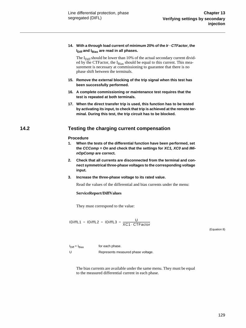
129
Line differential protection, phase segregated (DIFL)
Chapter 13Verifying settings by secondary
injection
14. With a through load current of minimum 20% of the Ir · CTFactor, the IDiff and IBias are read in all phases.
The IDiff should be lower than 10% of the actual secondary current divid-ed by the CTFactor, the IBias should be equal to this current. This mea-surement is necessary at commissioning to guarantee that there is no phase shift between the terminals.
15. Remove the external blocking of the trip signal when this test has been successfully performed.
16. A complete commissioning or maintenance test requires that the test is repeated at both terminals.
17. When the direct transfer trip is used, this function has to be tested by activating its input, to check that trip is achieved at the remote ter-minal. During this test, the trip circuit has to be blocked.
14.2 Testing the charging current compensation
Procedure1. When the tests of the differential function have been performed, set
the CCComp = On and check that the settings for XC1, XC0 and IMi-nOpComp are correct.
2. Check that all currents are disconnected from the terminal and con-nect symmetrical three-phase voltages to the corresponding voltage input.
3. Increase the three-phase voltage to its rated value.
Read the values of the differential and bias currents under the menu:
ServiceReport/DiffValues
They must correspond to the value:
(Equation 8)
The bias currents are available under the same menu. They must be equal to the measured differential current in each phase.
IDiff = IBias for each phase.
U Represents measured phase voltage.
IDiffL1 IDiffL2 IDiffL3 UXC1 CTFactor⋅--------------------------------------------= = =

130
Line differential protection, phase segregated (DIFL)
Chapter 13Verifying settings by secondary
injection
4. Disconnect the voltages from the terminal and connect only one phase to all three voltage inputs of the terminal.
5. Increase the measured voltage to the rated phase value and observe the values of the differential and bias currents, presented on the ter-minal.
They must correspond to the following values:
(Equation 9)
(Equation 10)
6. With the terminal in normal operation, not in Test mode, and with the line energised, the IDiffL1, IDiffL2 and IDiffL3 are measured under the service report menu with CCComp temporary set to Off at both ter-minals. Thereafter measure the values with the CCComp set to On.
Note! Setting CCComp to Off might cause the terminal to trip. Therefore make sure that the trip outputs are blocked.
7. Check the charging current compensation by comparing the mea-sured IDiffLx values.
The measured IDiffLx shall be near zero in each separate phase with the CCC used.
8. Remove the external blocking of the trip signal when this test has been successfully performed.
14.3 Completing the testContinue to test another function or complete the test by setting the test mode to off.
IDiffL1 IDiffL2 IDiffL3 2 U⋅XC0 CTFactor⋅--------------------------------------------= = =
IBiasL1 IBiasL2 IBiasL3 UXC0 CTFactor⋅--------------------------------------------= = =

131
Supervision of AC input quantities (DA) Chapter 13Verifying settings by secondary
injection
15 Supervision of AC input quantities (DA)Stabilized ac current and voltage generators and corresponding current, voltage, power and fre-quency meters with very high accuracy are necessary for testing the alternating quantity mea-suring function. The operating ranges of the generators must correspond to the rated alternate current and voltage of each terminal.
Prepare the terminal for verification of settings as outlined in section “Preparing for test” in this chapter. Connect the generators and instruments to the corresponding input terminals of a unit under test.
15.1 Verifying the settings
Procedure1. Supply the terminal with voltages and currents.
Check that the values presented on the HMI unit correspond to the mag-nitude of input measured quantities within the limits of declared accura-cy. The mean service values are available under the submenu:
Service Report/ServiceValues
The phasors of up to five input currents and voltages are available under the submenu:
Service Report/Phasors/Primary
2. Check the operation of ADBS or IDBS when applicable. Compare with the expected values.
The operation of ADBS or IDBS function can be checked separately with the RepInt = 0 setting. The value on the HMI follows the changes in the input measuring quantity continuously.
3. Check the set operate levels of the monitoring function by changing the magnitude of input quantities and observing the operation of the corresponding output relays.
The output contact changes its state when the changes in the input mea-suring quantity are higher than the set values HIWARN, HIALARM, or lower than the set values LOWWARN, LOWALARM.
15.2 Completing the testContinue to test another function or complete the test by setting the test mode to off. Restore connections and settings to the original values, if they were changed for testing purpose.

132
Supervision of mA input quantities (MI) Chapter 13Verifying settings by secondary
injection
16 Supervision of mA input quantities (MI)A stabilized direct current generator and mA meter with very high accuracy for measurement of direct current is needed in order to test the dc measuring module. The generator operating range and the measuring range of the mA meter must be at least between -25 and 25 mA.
Prepare the terminal for verification of settings as outlined in section 2 "Preparing for test" in this chapter. Connect the current generator and mA meter to the direct current input channels to be tested.
16.1 Verifying the settings
Procedure1. Consider the need to block output signals.
2. Check that the values presented on the HMI module corresponds to the magnitude of input direct current within the limits of declared ac-curacy.
The service value is available under the submenu:
Service Report/I/O/Slotnm-MIMx/MIxy-Value
3. Check the operation of ADBS or IDBS function when applicable. Compare with the expected values.
The operation of ADBS or IDBS function can be checked separately with the setting of RepInt = 0. The value on the HMI must change only when the changes in input current (compared to the present value) are higher than the set value for the selected dead band.
4. Check the operating monitoring levels by changing the magnitude of input current and observing the operation of the corresponding out-put relays.
The output contact changes its state when the changes in the input mea-suring quantity are higher than the set values RMAXAL, HIWARN, HI-ALARM, or lower than the set values LOWWARN, LOWALARM, RMINAL.
where:
nm represents the serial number of a slot with tested mA input module
x represents the serial number of a mA input module in a terminal
y represents the serial number of a measuring channel on module x.

133
Supervision of mA input quantities (MI) Chapter 13Verifying settings by secondary
injection
16.2 Completing the testContinue to test another function or complete the test by setting the test mode to off. Restore connections and settings to the original values, if they were changed for testing purpose.

134
Multiple command (CM) Chapter 13Verifying settings by secondary
injection
17 Multiple command (CM)Test of the multiple command function block is recommended to be performed in a system, that is, either in a complete delivery system as an acceptance test (FAT/SAT) or as parts of that sys-tem, because the command function blocks are connected in a delivery-specific way between bays and the station level.
Command function blocks included in the operation of different built-in functions must be tested at the same time as their corresponding functions.

135
Overload supervision (OVLD) Chapter 13Verifying settings by secondary
injection
18 Overload supervision (OVLD)Prepare the terminal for verification of settings as outlined in section 2 "Preparing for test" in this chapter.
18.1 Measuring the operate and time limit of set values
Procedure1. Check that the input logical signals OVLD-BLOCK is logical zero and
note on the local HMI that the OVLD-TRIP logical signal is equal to the logical 0.
Logical signals for overload supervision protection are available under menu tree:
ServiceReport/Functions/OverLoad/FuncOutputs
2. Quickly set the measured current (fault current) in all three phases to about 110% of the setting operating current, and switch off the current with the switch.
Observe the maximum permitted overloading of the current circuits in the terminal.
3. Switch on the fault current and measure the operating time of the OVLD protection.
Use the OVLD-TRIP signal from the configured binary output to stop the timer.
4. Compare the measured time with the set value t.
5. Activate the OVLD-BLOCK binary input.
6. Switch on the fault current (110% of setting) and wait longer than the set value t.
No OVLD-TRIP signal should appear.
7. Switch off the fault current.
8. Reset the OVLD-BLOCK binary input.
9. Quickly set the measured current (fault current) in all three phases to about 90% of the measured operating current, and switch off the current with the switch.
10. Switch on the fault current and wait longer than the set value t.
No OVLD--TRIP signal should appear.
11. Switch off the fault current.

136
Overload supervision (OVLD) Chapter 13Verifying settings by secondary
injection
12. Continue to test another function or complete the test by setting the test mode to off.

137
Pole discordance protection (PD) Chapter 13Verifying settings by secondary
injection
19 Pole discordance protection (PD)Prepare the terminal for verification of settings as outlined in section 2 "Preparing for test" in this chapter.
Procedure1. Activate the PD---POLDISC binary input, and measure the operating
time of the PD protection.
Use the PD---TRIP signal from the configured binary output to stop the timer.
2. Compare the measured time with the set value t.
3. Reset the PD---POLDISC binary input.
4. Activate the PD---1POPEN binary input.
(This test should be performed together with AR).
5. Activate the PD---POLDISC binary input.
No PD---TRIP signal should appear.
6. Reset both PD---1POPEN and PD---POLDISC binary inputs.
7. Activate the PD---BLOCK binary input.
8. Activate the PD---POLDISC binary input.
No PD---TRIP signal should appear.
9. Reset both PD---BLOCK and PD---POLDISC binary inputs.
10. Continue to test another function or complete the test by setting the test mode to off.

138
Pulse counter logic for metering (PC) Chapter 13Verifying settings by secondary
injection
20 Pulse counter logic for metering (PC)The test of the pulse counter function requires at least the PST Parameter Setting Tool or SPA (or LON) connection to a station HMI including corresponding functionality. A known number of pulses are with different frequency connected to the pulse counter input. The test should be performed for the settings operation = Off/On and for blocked/deblocked function. The pulse counter value is then read by the PST or station HMI.

139
Setting lockout (HMI) Chapter 13Verifying settings by secondary
injection
21 Setting lockout (HMI)
21.1 Verifying the settingsPrepare the terminal for verification of settings as outlined in section 2 "Preparing for test" in this chapter.
Procedure1. Configure the HMI--BLOCKSET functional input to the binary input,
which is determined by the engineering or the input that is not used by any other function.
2. Set the setting restriction to SettingRestrict = Block.
3. Connect rated DC voltage to the selected binary input.
4. Try to change the setting of any parameter for one of the functions.
Reading of the values must be possible.
The terminal must not respond to any attempt to change the setting value or configuration.
5. Disconnect the control DC voltage from the selected binary input.
6. Repeat the attempt under step 4.
The terminal must accept the changed setting value or configuration.
7. Depending on the requested design for a complete REx 5xx terminal, leave the function active or reconfigure the function into the default configuration and set the setting restriction function out of opera-tion to SettingRestrict = Open.
21.2 Completing the testContinue to test another function or complete the test by setting the test mode to off. Restore connections and settings to the original values, if they were changed for testing purpose.

140
Four parameter setting groups (GRP) Chapter 13Verifying settings by secondary
injection
22 Four parameter setting groups (GRP)
22.1 Verifying the settingsPrepare the terminal for verification of settings as outlined in section 2 "Preparing for test" in this chapter.
Procedure1. Check the configuration of binary inputs that control the selection of
active setting group.
2. Browse the ‘ActiveGroup’ menu to achieve information about the ac-tive setting group.
The ActiveGroup menu is located in the local HMI under:
ServiceReport/ActiveGroup
3. Connect the appropriate dc voltage to the corresponding binary in-put of the terminal and observe the information presented on the HMI display.
The displayed information must always correspond to the activated input.
4. Check that corresponding output indicates the active group.
5. Continue to test another function or complete the test by setting the test mode to off.

141
Single command (CD) Chapter 13Verifying settings by secondary
injection
23 Single command (CD)For the single command function block, it is necessary to configure the output signal to corre-sponding binary output of the terminal. The operation of the function is then checked from the local HMI by applying the commands with the MODE Off, Steady, or Pulse and by observing the logic statuses of the corresponding binary output.
Command control functions included in the operation of different built-in functions must be test-ed at the same time as their corresponding functions.

142
Thermal phase overload protection (THOL) Chapter 13Verifying settings by secondary
injection
24 Thermal phase overload protection (THOL)Prepare the terminal for verification of settings as outlined in section 2 "Preparing for test" in this chapter.
Check that the input logical signal THOL-BLOCK is logical zero and note on the local HMI that the logical signal THOL-TRIP, THOL-START and THOL-ALARM are equal to the logical 0. Logical signals for thermal overload protection are available under menu tree:
ServiceReport/Functions/ThermOverLoad/FuncOutputs
24.1 Measuring the operate and time limit of set values
24.1.1 Testing the protection without external temperature compensation (NonComp)
Procedure1. Quickly set the measured current (fault current) in one phase to
about 300% of I1b (to minimise the trip time), and switch off the cur-rent.
2. Reset the thermal memory under menu tree:
Test/ThermReset
3. Switch on the fault current and read the presented temperature:
ServiceReport/Functions/ThermOverload/ThermOverload/T Line
4. Check the Alarm limit (TAlarm) during injection.
Measure the signal THOL-ALARM until it appears on the corresponding binary output or on the local HMI unit.
5. Compare the measured temperature with the setting.
6. Measure the trip time of the THOL protection.
Use the THOL-TRIP signal from the configured binary output to stop the timer.
7. Take the “T Line” readings.
Compare with the setting of TTrip.
8. Activate the THOL-BLOCK binary input.
The signals THOL-ALARM, THOL-START and THOL-TRIP should disappear.
9. Reset the THOL-BLOCK binary input.

143
Thermal phase overload protection (THOL) Chapter 13Verifying settings by secondary
injection
10. Check the reset limit (TdReset).
Measure the signal THOL-START until it disappears on the correspond-ing binary output or on the local HMI unit, take the “T Line” readings and compare with the setting of TdReset.
11. Compare the measured trip time with the setting according to the formula.
12. Reset the thermal memory.
13. Continue to test another function or complete the test by setting the test mode to off.

144
Definite time non-directional overcurrent protection (TOC)
Chapter 13Verifying settings by secondary
injection
25 Definite time non-directional overcurrent protection (TOC)Prepare the terminal for verification of settings as outlined in section 2 "Preparing for test" in this chapter.
To verify the settings the following fault type should be tested:
• One for a phase-to-earth fault
Ensure that the maximum continuous current of the terminal does not exceed four times its rated value.
25.1 Measuring the operate limit of set values
25.1.1 Time delayed phase overcurrent
Procedure1. Inject a phase current in the terminal with start below the setting val-
ue.
2. Increase the injected current (measured current) in the Ln phase un-til the starting signal TOC--STLn (n=1-3) appears.
3. Switch off the fault current.
Observe the maximum permitted overloading of the current circuits in the terminal.
4. Compare the measured operating current with the set value IP>.
5. Set the fault current to about 1.5 times the measured operating cur-rent.
6. Switch on the fault current and measure the operating time of the TOC protection. Use the TOC--TRP signal.
7. Compare the measured time with the set value tP.
25.1.2 Time delayed residual overcurrent (non-dir.)
Procedure1. Inject a phase current in the terminal with start below the setting val-
ue.
2. Increase the injected residual current (measured current) in the Ln phase until the starting signal TOC--STN appears.
3. Switch off the fault current.
Observe the maximum permitted overloading of the current circuits in the terminal.

145
Definite time non-directional overcurrent protection (TOC)
Chapter 13Verifying settings by secondary
injection
4. Compare the measured operating current with the set value IN>.
5. Set the fault current to about 1.5 times the measured operating cur-rent.
6. Switch on the fault current and measure the operating time of the TOC protection. Use the TOC--TRN signal.
7. Compare the measured time with the set value tN.
25.2 Completing the testContinue to test another function or complete the test by setting the test mode to off.

146
Tripping logic (TR) Chapter 13Verifying settings by secondary
injection
26 Tripping logic (TR)Prepare the terminal for verification of settings as outlined in section 2 "Preparing for test" in this chapter.
The function is tested functionally together with other protection functions (distance protection ZMn--, line differential protection DIFL-, earth-fault overcurrent protection IOC-- or TOC--, etc.) within the REx 5xx terminals. It is recommended to test the function together with the au-toreclosing function, when built into the terminal or when a separate external unit is used for the reclosing purposes.
26.1 3ph operating modeThe function must issue a three-phase trip in all cases, when trip is initiated by any protection or some other built-in or external function. The following functional output signals must always appear simultaneously: TRIP-TRIP, TRIP-TRL1, TRIP-TRL2, TRIP-TRL3 and TRIP-TR3P.
26.2 1ph/3ph operating modeThe following tests should be carried out in addition to some other tests, which depends on the complete configuration of a terminal:
Procedure1. Initiate one-by one different single-phase-to-earth faults.
Consider sufficient time interval between the faults, to overcome a re-claim time of eventually activated autoreclosing function. Only a sin-gle-phase trip should occur for each separate fault and only one of the trip outputs (TRIP-TRLn) should be activated at a time. Functional outputs TRIP-TRIP and TRIP-TR1P should be active at each fault. No other out-puts should be active.
2. Initiate different phase-to-phase and three-phase faults.
Consider sufficient time interval between the faults, to overcome a re-claim time of eventually activated autoreclosing function. Only a three-phase trip should occur for each separate fault and all of the trip outputs (TRIP-TRLn) should be activated at a time. Functional outputs TRIP-TRIP and TRIP-TR3P should be active at each fault. No other out-puts should be active.
3. Initiate a single-phase-to-earth fault and switch it off immediately when the trip signal is issued for the corresponding phase. Initiate the same fault once again within the reclaim time of the used autore-closing function.
A three-phase trip must be initiated for the second fault.
Check that the corresponding trip signals appear after both faults.

147
Tripping logic (TR) Chapter 13Verifying settings by secondary
injection
If not the autoreclosing function is used the functional outputs TRIP-TRIP, TRIP-TR1P and the corresponding phase signal (TRIP-TRLn) should be active at each fault.
4. Initiate a single-phase-to-earth fault and switch it off immediately when the trip signal is issued for the corresponding phase. Initiate the second single-phase-to-earth fault in one of the remaining phas-es within the time interval, shorter than two seconds and shorter than the dead-time of the autoreclosing function, when included in protection scheme.
Check that the second trip is a three-phase trip.
26.3 1ph/2ph/3ph operating modeThe following tests should be carried out in addition to some other tests, which depends on the complete configuration of a terminal:
Procedure1. Initiate one-by one different single-phase-to-earth faults.
Consider sufficient time interval between the faults, to overcome a re-claim time of eventually activated autoreclosing function. Only a sin-gle-phase trip should occur for each separate fault and only one of the trip outputs (TRIP-TRLn) should be activated at a time. Functional outputs TRIP-TRIP and TRIP-TR1P should be active at each fault. No other out-puts should be active.
2. Initiate one-by one different phase-to-phase faults.
Consider sufficient time interval between the faults, to overcome a re-claim time of eventually activated autoreclosing function. Only a two-phase trip should occur for each separate fault and only correspond-ing two trip outputs (TRIP-TRLn) should be activated at a time. Func-tional outputs TRIP-TRIP and TRIP-TR2P should be active at each fault. No other outputs should be active.
3. Initiate a three-phase fault.
Consider sufficient time interval between the faults, to overcome a re-claim time of eventually activated autoreclosing function. Only a three-phase trip should occur for the fault and all trip outputs (TRIP-TRLn) should be activated at the same time. Functional outputs TRIP-TRIP and TRIP-TR3P should be active at each fault. No other out-puts should be active.
4. Initiate a single-phase-to-earth fault and switch it off immediately when the trip signal is issued for the corresponding phase. Initiate the same fault once again within the reclaim time of the used autore-closing function.
A three-phase trip must be initiated for the second fault.
Check that the corresponding trip signals appear after both faults.

148
Tripping logic (TR) Chapter 13Verifying settings by secondary
injection
If not the autoreclosing function is used the functional outputs TRIP-TRIP, TRIP-TR1P and the corresponding phase signal (TRIP-TRLn) should be active at each fault.
5. Initiate a single-phase-to-earth fault and switch it off immediately when the trip signal is issued for the corresponding phase. Initiate the second single-phase-to-earth fault in one of the remaining phas-es within the time interval, shorter than two seconds and shorter than the dead-time of the autoreclosing function, when included in protection scheme.
Check that the second trip is a single-phase trip in a second initiated phase.
6. Initiate a phase-to-phase fault and switch it off immediately when the trip signal is issued for the corresponding two phases. Initiate anoth-er phase-to-phase fault (not between the same phases) within the time, shorter than 2 seconds.
Check, that the output signals, issued for the first fault, correspond to two-phase trip for included phases.
The output signals for the second fault must correspond to the three-phase tripping action.
26.4 Completing the testContinue to test another function or complete the test by setting the test mode to off.

149
Two step time delayed non-directional phase overcurrent protection (TOC2)
Chapter 13Verifying settings by secondary
injection
27 Two step time delayed non-directional phase overcurrent protection (TOC2)Prepare the terminal for test as outlined in section 2 "Preparing for test" in this chapter.
Ensure that the maximum continuos current of a terminal does not exceed four times its rated value, if the measurement od the operating characteristics runs under constant voltage condi-tions.
To verify the settings the following fault type should be tested:
• One for a phase-to-earth fault
27.1 Measuring the operate and time limit for set values
27.1.1 Measuring the operate limit of the low step overcurrent protection
Procedure1. Inject a phase current slightly smaller than the functional value
I>Low.
2. Increase the current slowly and check the function value by observ-ing when the signal TOC2-STLS appears.
3. Compare the result of the measurement with the set value.
27.1.2 Measuring the definite time delay of the low set stage
Procedure1. Set a current 1.5 times I>Low on the injection test equipment.
2. Switch the current on and compare the operation time on TOC2-TRLS with the set value tLow.
The operate time shall be tLow+operate time of the low set stage.
27.1.3 Measuring the inverse time delay of the low set stage
Procedure1. Set temporarily tLow = 0.000 s.
If I>Low is set higher than I>Inv, check that there is no trip signal TOC2-TRLS when the current is less than I>Low.
2. Check the time delay at two points of the inverse time curve.
Check with the current I>Low or 2·I>Inv (the highest value of these two) and the current that according to the inverse time curve corresponds to tMin.
3. Increase the current 10% and check that the operation time is equal to tMin.

150
Two step time delayed non-directional phase overcurrent protection (TOC2)
Chapter 13Verifying settings by secondary
injection
4. Set tLow to the correct value and check with a high current that the operation time is equal to tMin+tLow.
27.1.4 Measuring the operate limit of the high step overcurrent protection
1. Set temporarily tHigh=0.000 s.
2. Inject a phase current slightly smaller than the operation value I>High.
3. Increase the current slowly and check the operation value by observ-ing when the signal TOC2-TRHS appears.
4. Compare the result of the measurement with the set value.
5. Set tHigh to the correct value.
6. Set a current 1.5 times I>High on the injection test equipment
7. Switch the current on and compare the operation time with the set value tHigh.
27.2 Completing the testContinue to test another function or complete the test by setting the test mode to off. Restore connections and settings to the original values, if they were changed for testing purpose.
151
Sudden change in phase current protection (SCC1)
Chapter 13Verifying settings by secondary
injection
28 Sudden change in phase current protection (SCC1)Prepare the terminal for verification of settings as outlined in section 2 "Preparing for test" in this chapter.
28.1 Measuring the operate limit of set values
28.1.1 Sudden change in current in any phaseThe sudden change in current protection algorithm measures the difference in amplitude of the current between two consecutive periods, and compares this difference to a set value.
28.1.2 Dependability test
Procedure1. Inject a three-phase balanced current, close to the rated secondary
current.
2. Measure the current that corresponds to a single phase, with an ex-ternal device.
3. Activate the SCC1_CR binary input.
4. Make a rapid small positive step-change of the current in the select-ed phase.
5. Check if the SCC1_START (or SCC1_TRIP) signal appears.
6. Compare the measured change in current with the set value DIL>.
7. Repeat item 4-6, with successively increased step-size, until the SCC1_START (or SCC1_TRIP) signal appears.
8. Repeat item 1-7, with a lower/higher current in item 1.
9. Repeat item 1-8, with a negative step-change in item 4.
10. Repeat item 1-9 for the other two phases.
28.1.3 Time delay test
Procedure1. Inject a three-phase balanced current, close to the rated secondary
current.
2. Prepare measurement of the time between the sudden change in cur-rent and the appearance of the SCC1_START (SCC1_TRIP) signal.
3. Activate the SCC1_CR binary input.
4. Make a rapid step-change of the current, significantly larger than the set value DIL>, in the selected phase.

152
Sudden change in phase current protection (SCC1)
Chapter 13Verifying settings by secondary
injection
5. Measure the time between the change in current and the SCC1_START (SCC1_TRIP) signal.
6. Compare the measured time with the set values tHStart and tHTrip.
7. Repeat item 11-16 for the other two phases.
28.1.4 Completing the testContinue to test another function or complete the test by setting the test mode off.

153
Sudden change in residual current protection (SCRC)
Chapter 13Verifying settings by secondary
injection
29 Sudden change in residual current protection (SCRC)Prepare the terminal for verification of settings as outlined in section 2 "Preparing for test" in this chapter.
29.1 Measuring the operate limit of set values
29.1.1 Sudden change in residual currentThe sudden change in residual current protection algorithm measures the difference in amplitude of the residual current between two consecutive periods, and compares this difference to a set value.
29.1.2 Dependability test
Procedure1. Inject a three-phase balanced current, close to the rated secondary
current, and add a small residual current.
2. Measure the residual current, with an external device.
3. Activate the SCRC_CR binary input.
4. Make a rapid small positive step-change of the residual current.
5. Check if the SCRC_START (or SCRC_TRIP) signal appears.
6. Compare the measured change in residual current with the set value DIN>.
7. Repeat item 4-6, with successively increased step-size, until thRe-peat item 1-7, with a lower/higher balanced current in item 1.Repeat item 1-7, with a lower/higher balanced current in item 1.
8. Repeat item 1-8, with a larger residual current in item 1.
9. Repeat item 1-9, with a negative step-change in item 4.
29.1.3 Time delay test
Procedure1. Inject a three-phase balanced current, close to the rated secondary
current, and add a residual current.
2. Prepare measurement of the time between the sudden change in re-sidual current and the appearance of the SCRC_START (SCRC_TRIP) signal.
3. Activate the SCRC_CR binary input.
4. Make a rapid step-change of the residual current, significantly larger than the set value DIN>.

154
Sudden change in residual current protection (SCRC)
Chapter 13Verifying settings by secondary
injection
5. Measure the time between the change in residual current and the SCRC_START (SCRC_TRIP) signal.
6. Compare the measured time with the set values tHStart and tHTrip.
29.1.4 Completing the testContinue to test another function or complete the test by setting the test mode off.

155
Undercurrent protection (UCP) Chapter 13Verifying settings by secondary
injection
30 Undercurrent protection (UCP)Prepare the terminal for verification of settings as outlined in section 2 "Preparing for test" in this chapter.
30.1 Measuring the operate limit of set values
30.1.1 Undercurrent in any phase
30.1.2 Dependbility test
Procedure1. Inject a three-phase balanced current, close to the rated secondary
current.
2. Measure the the current in a single phase, with an external device.
3. Activate the UCP_CR binary input.
4. Slowly reduce the current in the selected phase until the start signal UCP_STHIGH appears
5. Compare the measured current with the set value ILHigh<.
6. Continue to slowly decrease the current in the selected phase until the start signal UCP_STLOW appears.
7. Compare the measured current with the set value ILLow<.
8. Repeat item 1-7 for the other two phases.
30.1.3 Time delay test
Procedure1. Inject a three-phase balanced current, close to the rated secondary
current. Prepare for a change of the injected current to a value be-tween the set values ILLow< and ILHigh<.
2. Change the level of the injected current and measure the operating time of the UCP function. Use the UCP_TRHIGH signal. Compare this operating time with the set value tHigh.
3. Inject a three-phase balanced current, close to the rated secondary current. Prepare for a change of the injected current to a value well below the set value ILLow.
4. Change the level of the injected current and measure the operating time of the UCP function. Use the UCP_TRLOW signal. Compare this operating time with the set value tLow.
30.1.4 Completing the testContinue to test another function or complete the test by setting the test mode off.

156
Phase overcurrent protection (OCP) Chapter 13Verifying settings by secondary
injection
31 Phase overcurrent protection (OCP)Prepare the terminal for verification of settings as outlined in section 2 "Preparing for test" in this chapter.
31.1 Measuring the operate limit of set values
31.1.1 Overcurrent in any phase
31.1.2 Dependability test
Procedure1. Inject a small three-phase balanced current.
2. Measure the current in a single phase, with an external decvice.
3. Activate the OCP_CR binary input.
4. Slowly increase the current in the selected phase until the start sig-nal OCP_STLOW appears
5. Compare the measured current with the set value ILLow>.
6. Continue to slowly increase the current in the selected phase until the start signal OCP_STHIGH appears.
7. Compare the measured current with the set value ILHigh>.
8. Repeat item 1-7 for the other two phases.
31.1.3 Time delay test
Procedure1. Inject a small three-phase balanced current. Prepare for a change of
the injected current to a value between the set values ILLow> and IL-High>.
2. Change the level of the injected current and measure the operating time of the OCP function. Use the OCP_TRLOW signal. Compare this operating time with the set value tLow.
3. Inject a small three-phase balanced current. Prepare for a change of the injected current to a value well above the set value ILHigh>.
4. Change the level of the injected current and measure the operating time of the OCP function. Use the OCP_TRHIGH signal. Compare this operating time with the set value tHigh.
31.1.4 Completing the testContinue to test another function or complete the test by setting the test mode off.

157
Residual overcurrent protection (ROCP) Chapter 13Verifying settings by secondary
injection
32 Residual overcurrent protection (ROCP)Prepare the terminal for verification of settings as outlined in section 2 "Preparing for test" in this chapter.
32.1 Measuring the operate limit of set values
32.1.1 Residual overcurrentThe residual overcurrent protection algorithm measures the amplitude of the residual current and compares with the set value.
32.1.2 Dependability test
Procedure1. Inject a three-phase balanced current, close to the rated secondary
current, and add a small residual current.
2. Measure the residual current, with an external device.
3. Acivate the ROCP_CR binary input.
4. Slowly increase the residual current until the start signal ROCP_STLOW appears.
5. Compare the measured residual current with the set value INLow>.
6. Continue to slowly increase the residual current until the start signal ROCP_STHIGH appears.
7. Compare the measured residual current with the set value INHigh>.
8. Repeat item 1-7, with a lower/higher balanced current in item 1.
32.1.3 Time delay test
Procedure1. Inject a three-phase balanced current, close to the rated secondary
current, and add a small residual current
2. Prepare for a change of the injected residual current to a value be-tween the set values INLow> and INHigh>.
3. Change the level of the injected residual current and measure the op-erating time of the ROCP function. Use the ROCP_TRLOW signal. Compare this operating time with the set value tLow.
4. Inject a three-phase balanced current, close to the rated secondary current, and add a small residual current
5. Prepare for a change of the injected residual current to a value well above the set value INHigh>.

158
Residual overcurrent protection (ROCP) Chapter 13Verifying settings by secondary
injection
6. Change the level of the injected current and measure the operating time of the ROCP function. Use the ROCP_TRHIGH signal. Compare this operating time with the set value tHigh
32.1.4 Completing the testContinue to test another function or complete the test by setting the test mode off.

159
About this chapter Chapter 14Verifying the internal configuration
Chapter 14 Verifying the internal configuration
About this chapterThe aim of this chapter is to verify that the internal communications and output signals are ac-cording to the specification and normal protection praxis. This means that all included protection functions must be in operation.

160
Overview Chapter 14Verifying the internal configuration
1 OverviewBefore start of this process, all individual devices that are involved in the fault clearance process must have been tested as individuals and set in operation. The breaker must be ready for an open-close-open cycle.
The shaping of the test process is dependent on the complexity of the design of the switchyard. Hereby follows some items which could be used as guidelines.

161
Testing the interaction of the distance protection
Chapter 14Verifying the internal configuration
2 Testing the interaction of the distance protectionThis procedure describes how to test the interaction of the distance protection zone 1 at phase L1-earth fault in forward direction. It is recommended that all other distance protection zones and other protection functions are tested in a similar way. The test must be done without the test switch in order to verify the interaction between the terminal and surrounding equipment. Make sure that all personnel is informed, also in remote station.
Procedure1. Make sure that the protection terminal and fitting breaker(s) to be
tested are in service.
2. Connect the test equipment to the terminal.
3. Set the test equipment so that the impedance present to the relay is half the set value.
4. Energise the protection terminal and evaluate the result i.e.
• Check that correct trip has been accomplished according to configu-ration and philosophy.
• Check that all binary output signals that should be activated have been activated.
• Check that all other protection functions that should be activated by this type of fault have been activated.
• Check that no other protection functions that should not be activated have not been activated.
• Check whenever applicable that the disturbance report, event list and disturbance recorder have been activated and performed correct in-formation.

162
Testing the interaction of the distance protection
Chapter 14Verifying the internal configuration

163
About this chapter Chapter 15Testing the protection system
Chapter 15 Testing the protection system
About this chapterThis chapter describes how to verify the conformity of the protection system without the pro-tected object energised.
164
Overview Chapter 15Testing the protection system
1 OverviewBefore start of this process, all individual devices that are involved in the fault clearance process of the protected object must have been tested as individuals and set in operation. The breaker must be ready for an open-close-open cycle.
Scheme performance test is the final test that should be carried out before the protected object is taken into service.
Due to the complexity in combination with already performed tests, it is not necessary to test all protection functions and all fault types in this process. The most important protection functions in the terminal for single line to earth fault and phase-phase fault could be used for the test.
The shaping of the test process is dependent on the complexity of the design of the switchyard. Hereby follows some items which could be used as guidelines.

165
Testing the interaction of the distance protection
Chapter 15Testing the protection system
2 Testing the interaction of the distance protectionThis procedure describes how to test the interaction of distance protection zone 1 at a transient phase L1-L2 fault in forward direction. The test must be done without the test switch in order to verify the interaction between the terminal and surrounding equipment. Make sure that involved personnel is informed also in remote station.
This procedure describes how to test the interaction of an overcurrent protection stage at a tran-sient phase L1-L2 fault in forward direction. The test must be done without the test switch in order to verify the interaction between the terminal and surrounding equipment. Make sure that involved personnel is informed also in remote station.
Procedure1. Make sure that the protection terminal and related breaker(s) to be
tested are in service.
2. Connect the test equipment to the terminal.
3. Set the test equipment so that the impedance present to the relay is half the set value of zone 1.
4. Prepare a transient fault sequence.
5. Simulate the condition for the synchro-check as for live bus and dead line.
6. Energise the protection terminal and evaluate the result i.e.
• Check that correct trip has been accomplished according to configu-ration and philosophy.
• Check that the autoreclosure have made an reclosing of the protected object.
• Check that activation of all other external devices have been accom-plished according to configuration and protection philosophy.- Check, whenever applicable, that carrier receive signal has ar-
rived at remote end.- Check, whenever applicable, that start of external disturbance
recorder has been accomplished.- Check that event and alarm signals has been given etc.
• Check that no abnormal events have occurred.• Notice the AR dead time and do corrections if needed.
7. Make a new fault case for permanent fault and repeat the steps 1 - 6 above.
Specially note that a permanent trip should occur after the last attempt ac-cording to the programming of the AR.
It is recommended to repeat the procedure 1 - 6 for a protection function which detects earth-faults i.e. residual overcurrent protection.

166
Testing the interaction of the distance protection
Chapter 15Testing the protection system

167
About this chapter Chapter 16Fault tracing and repair
Chapter 16 Fault tracing and repair
About this chapterThis chapter describes how to carry out fault tracing and eventually, a change of circuit board.

168
Fault tracing Chapter 16Fault tracing and repair
1 Fault tracing
1.1 Using information on the local HMIIf an internal fault has occurred, the local HMI displays information under:
TerminalReportSelfSuperv
Under these menus the indications of eventual internal failure (serious fault) or internal warning (minor problem) are listed.
Shown as well, are the indications regarding the faulty unit according to table 24.
Table 24: HMI information
Also the internal signals, such as INT--FAIL and INT--WARNING can be connected to binary output contacts for signalling to a control room.
In the Terminal Status - Information, the present information from the self-supervision function can be viewed. Indications of failure or warnings for each hardware module are provided, as well as information about the external time synchronisation and the internal clock. All according to table 25. Loss of time synchronisation can be considered as a warning only. The REx 5xx ter-minal has full functionality without time synchronisation.
HMI information Signal name Activates sum-mary signal
Description
InternFail INT--FAIL Internal fail sum-mary
Intern Warning INT--WARNING Internal warning summary
CPU-modFail INT--CPUFAIL INT--FAIL Main processing module failed
CPU-modWarning INT--CPUWARN INT--WARNING Main processing module warning (failure of clock, time synch., fault locator or distur-bance recorder)
ADC-module INT--ADC INT--FAIL A/D conversion module failed
Slotnn-XXXyy INT--IOyy INT--FAIL I/O module yy failed
Real Time Clock INT--RTC INT--WARNING Internal clock is reset - Set the clock
Time Sync INT--TSYNC INT--WARNING No time synchroni-sation

169
Fault tracing Chapter 16Fault tracing and repair
1.2 Using front-connected PC or SMS• Self-supervision summary = INT--FAIL and INT--WARNING• CPU-module status summary = INT--CPUFAIL and INT--CPUWARN
When an internal fault has occurred, extensive information can be retrieved about the fault from the list of internal events. The list is available in the TERM-STS Terminal Status part of the CAP tool. This time-tagged list has information with the date and time of the last 40 internal events.
The internal events in the list do not only refer to faults in the terminal, but also to other activi-ties, such as change of settings, clearing of disturbance reports and loss of external time synchro-nisation
The following events are logged as Internal events:
Table 25: Internal events
The events in the internal event list are time tagged with a resolution of 1 ms.
This means that when using the PC for fault tracing, it provides information on the:
Event message Description Set/reset event
INT--FAILOff Internal fail status Reset event
INT--FAILOn Set event
INT--WARNINGOff Internal warning status Reset event
INT--WARNINGOn Set event
INT--CPUFAILOff Main processing module fatal error status
Reset event
INT--CPUFAILOn Set event
INT--CPUWARNOff Main processing module non-fatal error status
Reset event
INT--CPUWARNOn Set event
INT--ADCOff A/D conversion module status Reset event
INT--ADCOn Set event
INT--IOnOff In/Out module No. n status Reset event
INT--IOn On Set event
INT--RTC Off Real Time Clock (RTC) status Reset event
INT--RTC On Set event
INT--TSYNC Off External time synchronisation sta-tus
Reset event
INT--TSYNC On Set event
DREP-MEMUSED On >80% of the disturbance record-ing memory used
Set event
SETTING CHANGED Any settings in terminal changed
DISTREP CLEARED All disturbances in Disturbance report cleared

170
Fault tracing Chapter 16Fault tracing and repair
• Module that should be changed.• Sequence of faults, if more than one unit is faulty.• Exact time when the fault occurred.

171
Repair instruction Chapter 16Fault tracing and repair
2 Repair instruction
An alternative is to open the terminal and send only the faulty circuit board to ABB for repair. When a printed circuit board is sent to ABB, it must always be placed in a metallic, ESD-proof, protection bag. The user can also purchase separate modules for replacement.
Most electronic components are sensitive to electrostatic discharge and latent damage may oc-cur. Please observe usual procedures for handling electronics and also use an ESD wrist strap. A semi-conducting layer must be placed on the workbench and connected to earth.
Disassemble and reassemble the REx 5xx terminal accordingly:
1. Switch off the dc supply.2. Short-circuit the current transformers and disconnect all current and voltage con-
nections from the terminal.3. Disconnect all signal wires by removing the female connectors.4. Disconnect the optical fibres.5. Unscrew the main back plate of the terminal.6. If the transformer module is to be changed — unscrew the small back plate of the
terminal.7. Pull out the faulty module.8. Check that the new module has correct identity number.
Warning!Never disconnect a secondary connection of current transformer circuit without short-circuiting the transformer’s secondary winding. Operating a current transformer with the secondary winding open will cause a massive potential build-up that may damage the transformer and may cause injuries to humans.
Warning!Never connect or disconnect a wire and/or a connector to or from a terminal during normal ser-vice. Hazardous voltages and currents are present that may be lethal. Operation may be disrupt-ed and terminal and measuring circuitry may be damaged.
Note!Strictly follow the company and country safety regulations.
Caution!Always use a conductive wrist strap connected to protective earth when replacing modules. Electrostatic discharge (ESD) may damage the module and terminal circuitry.

172
Repair instruction Chapter 16Fault tracing and repair
9. Check that the springs on the card rail have connection to the corresponding me-tallic area on the circuit board when the new module is inserted.
10. Reassemble the terminal.
If the REx 5xx terminal has the optional increased measuring accuracy, a file with unique cali-bration data for the transformer module is stored in the Main processing module. Therefore it is not possible to change only one of these modules with maintained accuracy.

173
Repair support Chapter 16Fault tracing and repair
3 Repair supportIf a REx 5xx terminal needs to be repaired, the whole terminal must be removed and sent to ABB Logistic Center. Before returning the material, an inquiry must be sent to ABB Logistic Center.
e-mail: [email protected]

174
Repair support Chapter 16Fault tracing and repair

ABB Power Technologies ABSubstation Automation ProductsSE-721 59 VästeråsSwedenTelephone: +46 (0) 21 34 20 00Facsimile: +46 (0) 21 14 69 18Internet: www.abb.com/substationautomation
1MR
K 5
06 1
51-U
EN
Printed on recycled and ecolabelled paper at Elanders Novum