Embed Size (px)
Citation preview
HVAC APPLICATIONS

INTRODUCTION
Quality of living 04
HVAC with Ekinex® 05
The KNX standard 06
Products 08
HVAC APPLICATIONS HVAC APPLICATIONS
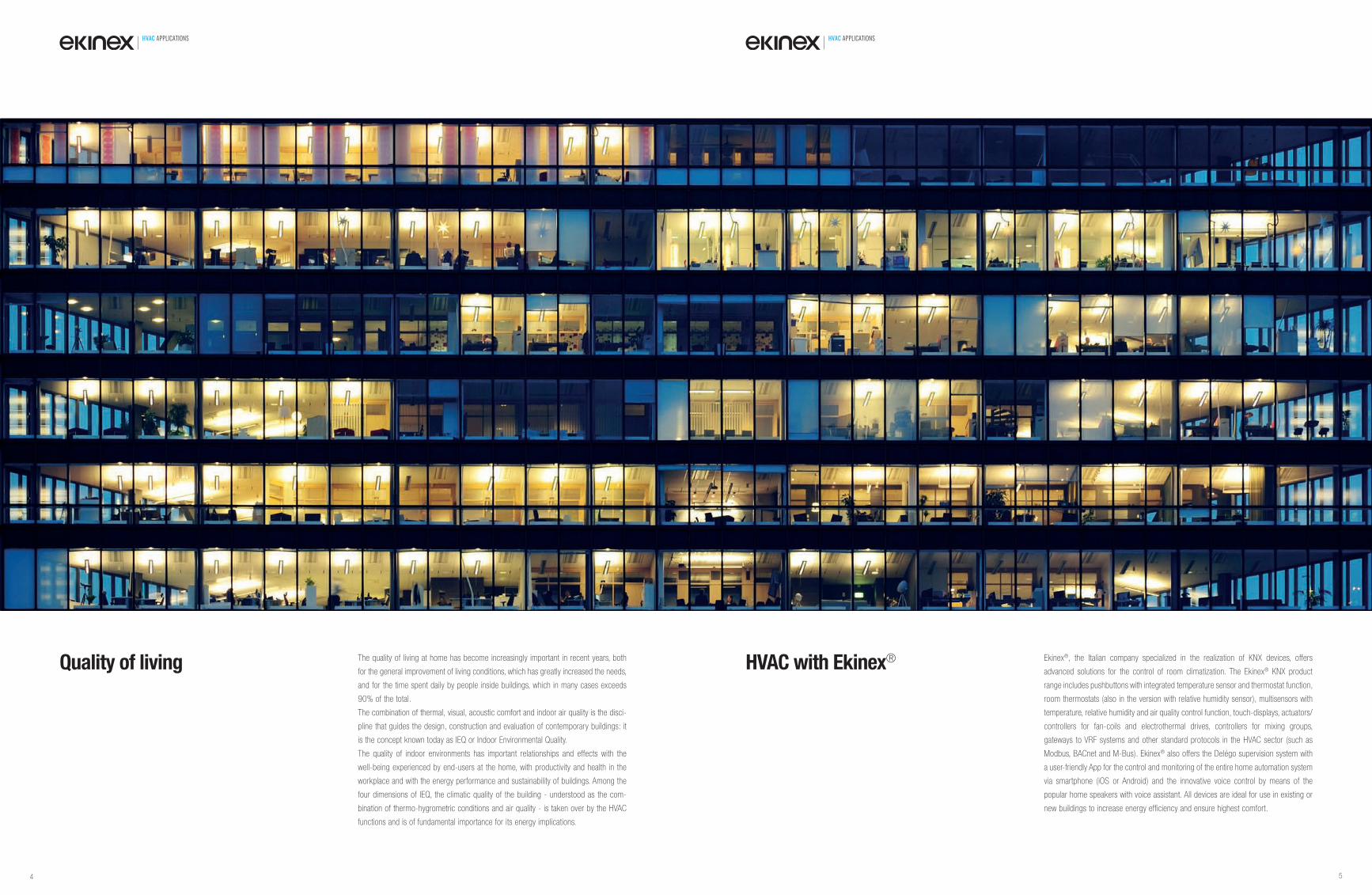
Quality of living The quality of living at home has become increasingly important in recent years, both
for the general improvement of living conditions, which has greatly increased the needs,
and for the time spent daily by people inside buildings, which in many cases exceeds
90% of the total.
The combination of thermal, visual, acoustic comfort and indoor air quality is the disci-
pline that guides the design, construction and evaluation of contemporary buildings: it
is the concept known today as IEQ or Indoor Environmental Quality.
The quality of indoor environments has important relationships and effects with the
well-being experienced by end-users at the home, with productivity and health in the
workplace and with the energy performance and sustainability of buildings. Among the
four dimensions of IEQ, the climatic quality of the building - understood as the com-
bination of thermo-hygrometric conditions and air quality - is taken over by the HVAC
functions and is of fundamental importance for its energy implications.
HVAC with Ekinex® Ekinex®, the Italian company specialized in the realization of KNX devices, offers
advanced solutions for the control of room climatization. The Ekinex® KNX product
range includes pushbuttons with integrated temperature sensor and thermostat function,
room thermostats (also in the version with relative humidity sensor), multisensors with
temperature, relative humidity and air quality control function, touch-displays, actuators/
controllers for fan-coils and electrothermal drives, controllers for mixing groups,
gateways to VRF systems and other standard protocols in the HVAC sector (such as
Modbus, BACnet and M-Bus). Ekinex® also offers the Delégo supervision system with
a user-friendly App for the control and monitoring of the entire home automation system
via smartphone (iOS or Android) and the innovative voice control by means of the
popular home speakers with voice assistant. All devices are ideal for use in existing or
new buildings to increase energy efficiency and ensure highest comfort.
4 5
HVAC APPLICATIONS HVAC APPLICATIONS
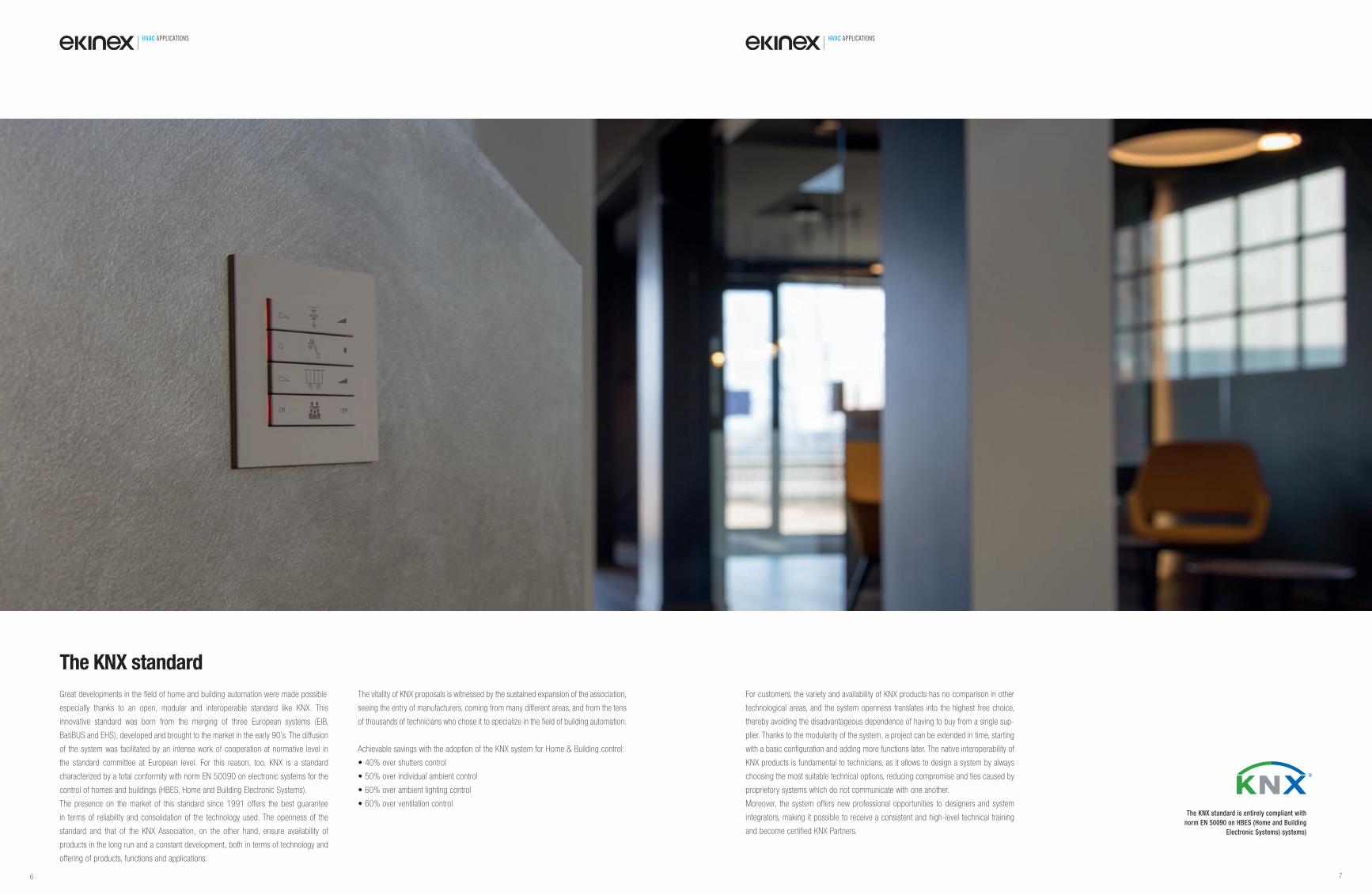
Great developments in the field of home and building automation were made possible
especially thanks to an open, modular and interoperable standard like KNX. This
innovative standard was born from the merging of three European systems (EIB,
BatiBUS and EHS), developed and brought to the market in the early 90’s. The diffusion
of the system was facilitated by an intense work of cooperation at normative level in
the standard committee at European level. For this reason, too, KNX is a standard
characterized by a total conformity with norm EN 50090 on electronic systems for the
control of homes and buildings (HBES, Home and Building Electronic Systems).
The presence on the market of this standard since 1991 offers the best guarantee
in terms of reliability and consolidation of the technology used. The openness of the
standard and that of the KNX Association, on the other hand, ensure availability of
products in the long run and a constant development, both in terms of technology and
offering of products, functions and applications.
The vitality of KNX proposals is witnessed by the sustained expansion of the association,
seeing the entry of manufacturers, coming from many different areas, and from the tens
of thousands of technicians who chose it to specialize in the field of building automation.
Achievable savings with the adoption of the KNX system for Home & Building control:
• 40% over shutters control
• 50% over individual ambient control
• 60% over ambient lighting control
• 60% over ventilation control
For customers, the variety and availability of KNX products has no comparison in other
technological areas, and the system openness translates into the highest free choice,
thereby avoiding the disadvantageous dependence of having to buy from a single sup-
plier. Thanks to the modularity of the system, a project can be extended in time, starting
with a basic configuration and adding more functions later. The native interoperability of
KNX products is fundamental to technicians, as it allows to design a system by always
choosing the most suitable technical options, reducing compromise and ties caused by
proprietory systems which do not communicate with one another.
Moreover, the system offers new professional opportunities to designers and system
integrators, making it possible to receive a consistent and high-level technical training
and become certified KNX Partners.
The KNX standard
The KNX standard is entirely compliant with
norm EN 50090 on HBES (Home and Building
Electronic Systems) systems)
6 7
HVAC APPLICATIONS HVAC APPLICATIONS
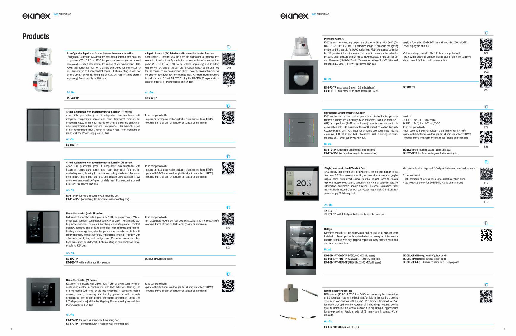
4-fold pushbutton with room thermostat function (FF series)
4-fold KNX pushbutton (max. 8 independent bus functions), with integrated temperature sensor and room thermostat function, for controlling loads, dimming luminaires, controlling blinds and shutters or other programmable bus functions. Confi gurable LEDs available in two colour combinations (blue / green or white / red). Flush-mounting on round wall box. Power supply via KNX bus.
To be completed with:- square or rectangular rockers (plastic, aluminium or Fenix NTM®)- optional frame of form or fl ank series (plastic or aluminium)
Art.-No.
EK-ED2-TP
4-fold pushbutton with room thermostat function (71 series)
4-fold KNX pushbutton (max. 8 independent bus functions), with integrated temperature sensor and room thermostat function, for controlling loads, dimming luminaires, controlling blinds and shutters or other programmable bus functions. Confi gurable LEDs available in two colour combinations (blue / green or white / red). Flush-mounting on wall box. Power supply via KNX bus.
To be completed with:- square or rectangular rockers (plastic, aluminium or Fenix NTM®)- plate with 60x60 mm window (plastic, aluminium or Fenix NTM®)- optional frame of form or fl ank series (plastic or aluminium)
Art.-No.
EK-E12-TP (for round or square wall-mounting box)EK-E12-TP-R (for rectangular 3-modules wall-mounting box)
Room thermostat (serie FF series)
KNX room thermostat with 2-point (ON / OFF) or proportional (PWM or continuous) control in combination with KNX actuators. Heating and coo-ling modes with local or via bus switching. 4 operating modes: comfort, standby, economy and building protection with separate setpoints for heating and cooling. Integrated temperature sensor (also available with relative humidity sensor), two freely confi gurable inputs, LCD display with adjustable backlighting and confi gurable LEDs in two colour combina-tions (blue/green or white/red). Flush-mounting on round wall box. Power supply via KNX bus.
To be completed with:- set of 2 square rockers with symbols (plastic, aluminium or Fenix NTM®)- optional frame of form or fl ank series (plastic or aluminium)
EQ2
EP2
Art.-No.
EK-EP2-TP
EK-EQ2-TP (with relative humidity sensor)EK-ER2-TP (versione easy)
Room thermostat (71 series)
KNX room thermostat with 2-point (ON / OFF) or proportional (PWM or continuous) control in combination with KNX actuators. Heating and cooling modes with local or via bus switching. 4 operating modes: comfort, standby, economy and building protection with separate setpoints for heating and cooling. Integrated temperature sensor and LCD display with adjustable backlighting. Flush-mounting on wall box. Power supply via KNX bus.
To be completed with- plate with 60x60 mm window (plastic, aluminium or Fenix NTM®)- optional frame of form or fl ank series (plastic or aluminium)
Art.-No.
EK-E72-TP (for round or square wall-mounting box)EK-E72-TP-R (for rectangular 3-modules wall-mounting box)
Display and control unit Touch & See
KNX display and control unit for switching, control and display of bus functions. 3.5“ touchscreen operating surface with sequence of graphic pages: home (with direct access to other pages), room thermostat (up to 8 independent zones), switching and control, calendar, weather information, multimedia, service functions (presence simulation, timer, alarms). Flush-mounting on wall box. Power supply via KNX bus, auxiliary power supply 30 Vdc required.
Also available with integrated 2-fold pushbutton and temperature sensor.
To be completed:- optional frame of form or fl ank series (plastic or aluminium)- square rockers (only for EK-EF2-TP, plastic or aluminium)
EF2
EC2
Art.-No.
EK-EC2-TP
EK-EF2-TP (with 2-fold pushbutton and temperature sensor)
Delégo
Complete system for the supervision and control of a KNX standard installation. Developed with web-oriented technologies, it features a uniform interface with high graphic impact on every platform with local and remote connection.
Nr. art.
EK-DEL-SRV-BAS-TP (BASIC, 400 KNX addresses)EK-DEL-SRV-ADV-TP (ADVANCED, 1,200 KNX addresses)EK-DEL-SRV-PRM-TP (PREMIUM, 2,500 KNX addresses)
EK-DEL-5PAN Delégo panel 5” (black panel)EK-DEL-8PAN Delégo panel 8” (black panel)EK-DEL-5FR-GB... Aluminium frame for 5” Delégo panel
4 confi gurable input interface with room thermostat function
Confi gurable 4-channel KNX input for connecting potential-free contacts or passive NTC 10 kΩ at 25°C temperature sensors (to be ordered separately). 4 output channels for the control of low consumption LEDs. Room thermostat function for channels confi gured for connection to NTC sensors (up to 4 independent zones). Flush-mounting in wall box or on a DIN EN 60715 rail using the EK-SMG-35 support (to be ordered separately). Power supply via KNX bus.
4 input / 2 output (5A) interface with room thermostat function
Confi gurable 4-channel KNX input for the connection of potential-free contacts of which 1 confi gurable for the connection of a temperature probe (NTC 10 kΩ at 25°C, to be ordered separately) and 2 output channel with 5A relay for the control of electrical loads. 4 output channels for the control of low consumption LEDs. Room thermostat function for the channel confi gured for connection to the NTC sensor. Flush-mounting in wall box or on DIN rail EN 60715 using the EK-SMG-35 support (to be ordered separately). Power supply via KNX bus.
CG2
CE2
Art.-No. Art.-No.
EK-CG2-TP EK-CE2-TP
NTC temperature sensors
NTC sensors (10 kΩ at 25°C, ß = 3435) for measuring the temperature of the room air mass or the heat transfer fl uid in the heating / cooling system; in combination with Ekinex® KNX devices dedicated to HVAC functions, they optimise the operation of the building’s heating / cooling system, increasing the level of comfort and exploiting all opportunities for energy saving. Versions: external (E), immersion (I), contact (C), air mass (L).
Art.-No.
EK-STx-10K-3435 (x = E, I, C, L)
Products
Multisensor with thermostat function
KNX multisensor can be used as probe or controller for temperature, relative humidity and air quality (CO2 equivalent, TVOC). 2-point (ON / OFF) or proportional (PWM or continuous) room temperature control in combination with KNX actuators; threshold control of relative humidity, CO2 (equivalent) and TVOC, LEDs for signalling operation mode (heating / cooling), R.H., CO2 and TVOC thresholds. Wall mounting on fl ush-mounted box. Power supply via KNX bus.
Versions:EK-ET2-... for T, R.H., CO2 equiv.EK-ES2-... for T, R.H., CO2 eq., TVOCTo be completed with:- front cover with symbols (plastic, aluminium or Fenix NTM®)- plate with 60x60 mm window (plastic, aluminium or Fenix NTM®)- optional frame from form or fl ank series (plastic or aluminium)
ES2
ET2
Nr. art.
EK-ET2-TP (for round or square fl ush mounting box)EK-ET2-TP-R (for 3-part rectangular fl ush mount box)
EK-ES2-TP (for round or square fl ush mount box)EK-ES2-TP-R (for 3-part rectangular fl ush-mounting box)
Presence sensors
KNX sensors for detecting people standing or walking with 360° (EK-Dx2-TP) or 180° (EK-SM2-TP) detection range. 2 channels for lighting control and 2 channels for HVAC equipment. Motion/presence detection by PIR (passive infrared) sensors. The detection area can be extended by using other sensors confi gured as slave devices. Brightness sensor and IR receiver (EK-Dx2-TP only). Versions for ceiling (EK-Dx2-TP) or wall mounting (EK-SM2-TP). Power supply via KNX bus.
Versions for ceiling (EK-Dx2-TP) or wall mounting (EK-SM2-TP). Power supply via KNX bus.
Wall-mounting version EK-SM2-TP to be completed with: - plate with 60x60 mm window (plastic, aluminium or Fenix NTM®)- front cover EK-CLM-... with prismatic lens
SM2
DF2
DG2
Nr. art.
EK-DF2-TP (max. range 9 m with 2.5 m installation)EK-DG2-TP (max. range 12 m when installed at 2.5 m)
EK-SM2-TP
8 9
HVAC APPLICATIONS HVAC APPLICATIONS
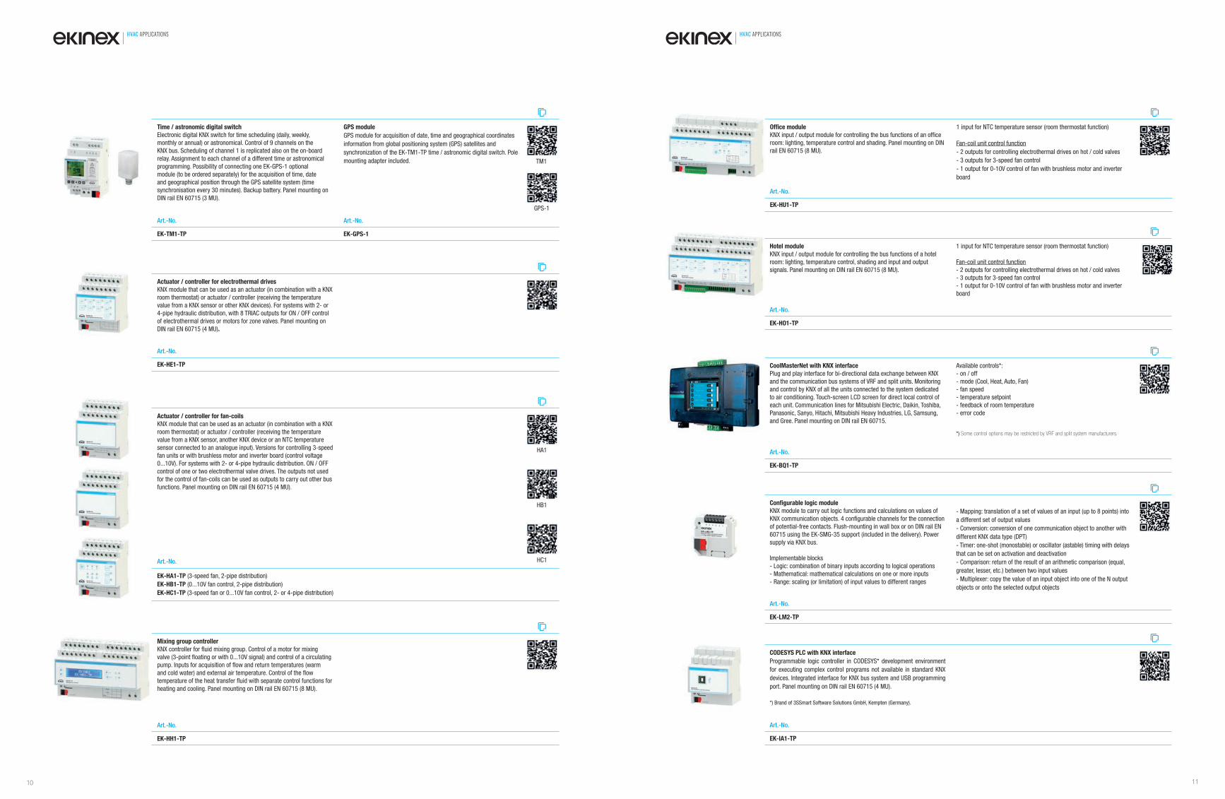
Actuator / controller for fan-coils
KNX module that can be used as an actuator (in combination with a KNX
room thermostat) or actuator / controller (receiving the temperature
value from a KNX sensor, another KNX device or an NTC temperature
sensor connected to an analogue input). Versions for controlling 3-speed
fan units or with brushless motor and inverter board (control voltage
0...10V). For systems with 2- or 4-pipe hydraulic distribution. ON / OFF
control of one or two electrothermal valve drives. The outputs not used
for the control of fan-coils can be used as outputs to carry out other bus
functions. Panel mounting on DIN rail EN 60715 (4 MU).
HA1
HB1
HC1Art.-No.
EK-HA1-TP (3-speed fan, 2-pipe distribution)
EK-HB1-TP (0...10V fan control, 2-pipe distribution)
EK-HC1-TP (3-speed fan or 0...10V fan control, 2- or 4-pipe distribution)
Actuator / controller for electrothermal drives
KNX module that can be used as an actuator (in combination with a KNX
room thermostat) or actuator / controller (receiving the temperature
value from a KNX sensor or other KNX devices). For systems with 2- or
4-pipe hydraulic distribution, with 8 TRIAC outputs for ON / OFF control
of electrothermal drives or motors for zone valves. Panel mounting on
DIN rail EN 60715 (4 MU).
Art.-No.
EK-HE1-TP
Confi gurable logic module
KNX module to carry out logic functions and calculations on values of
KNX communication objects. 4 confi gurable channels for the connection
of potential-free contacts. Flush-mounting in wall box or on DIN rail EN
60715 using the EK-SMG-35 support (included in the delivery). Power
supply via KNX bus.
Implementable blocks
- Logic: combination of binary inputs according to logical operations
- Mathematical: mathematical calculations on one or more inputs
- Range: scaling (or limitation) of input values to different ranges
- Mapping: translation of a set of values of an input (up to 8 points) into
a different set of output values
- Conversion: conversion of one communication object to another with
different KNX data type (DPT)
- Timer: one-shot (monostable) or oscillator (astable) timing with delays
that can be set on activation and deactivation
- Comparison: return of the result of an arithmetic comparison (equal,
greater, lesser, etc.) between two input values
- Multiplexer: copy the value of an input object into one of the N output
objects or onto the selected output objects
Art.-No.
EK-LM2-TP
Offi ce module
KNX input / output module for controlling the bus functions of an offi ce
room: lighting, temperature control and shading. Panel mounting on DIN
rail EN 60715 (8 MU).
1 input for NTC temperature sensor (room thermostat function)
Fan-coil unit control function
- 2 outputs for controlling electrothermal drives on hot / cold valves
- 3 outputs for 3-speed fan control
- 1 output for 0-10V control of fan with brushless motor and inverter
board
Art.-No.
EK-HU1-TP
CoolMasterNet with KNX interface
Plug and play interface for bi-directional data exchange between KNX
and the communication bus systems of VRF and split units. Monitoring
and control by KNX of all the units connected to the system dedicated
to air conditioning. Touch-screen LCD screen for direct local control of
each unit. Communication lines for Mitsubishi Electric, Daikin, Toshiba,
Panasonic, Sanyo, Hitachi, Mitsubishi Heavy Industries, LG, Samsung,
and Gree. Panel mounting on DIN rail EN 60715.
Available controls*:
- on / off
- mode (Cool, Heat, Auto, Fan)
- fan speed
- temperature setpoint
- feedback of room temperature
- error code
*) Some control options may be restricted by VRF and split system manufacturers.
Art.-No.
EK-BQ1-TP
Time / astronomic digital switch
Electronic digital KNX switch for time scheduling (daily, weekly,
monthly or annual) or astronomical. Control of 9 channels on the
KNX bus. Scheduling of channel 1 is replicated also on the on-board
relay. Assignment to each channel of a different time or astronomical
programming. Possibility of connecting one EK-GPS-1 optional
module (to be ordered separately) for the acquisition of time, date
and geographical position through the GPS satellite system (time
synchronisation every 30 minutes). Backup battery. Panel mounting on
DIN rail EN 60715 (3 MU).
GPS module
GPS module for acquisition of date, time and geographical coordinates
information from global positioning system (GPS) satellites and
synchronization of the EK-TM1-TP time / astronomic digital switch. Pole
mounting adapter included.
GPS-1
TM1
Art.-No. Art.-No.
EK-TM1-TP EK-GPS-1
CODESYS PLC with KNX interface
Programmable logic controller in CODESYS* development environment
for executing complex control programs not available in standard KNX
devices. Integrated interface for KNX bus system and USB programming
port. Panel mounting on DIN rail EN 60715 (4 MU).
*) Brand of 3SSmart Software Solutions GmbH, Kempten (Germany).
Art.-No.
EK-IA1-TP
Mixing group controller
KNX controller for fl uid mixing group. Control of a motor for mixing
valve (3-point fl oating or with 0...10V signal) and control of a circulating
pump. Inputs for acquisition of fl ow and return temperatures (warm
and cold water) and external air temperature. Control of the fl ow
temperature of the heat transfer fl uid with separate control functions for
heating and cooling. Panel mounting on DIN rail EN 60715 (8 MU).
Art.-No.
EK-HH1-TP
Hotel module
KNX input / output module for controlling the bus functions of a hotel
room: lighting, temperature control, shading and input and output
signals. Panel mounting on DIN rail EN 60715 (8 MU).
1 input for NTC temperature sensor (room thermostat function)
Fan-coil unit control function
- 2 outputs for controlling electrothermal drives on hot / cold valves
- 3 outputs for 3-speed fan control
- 1 output for 0-10V control of fan with brushless motor and inverter
board
Art.-No.
EK-HO1-TP
10 11
HVAC APPLICATIONS HVAC APPLICATIONS
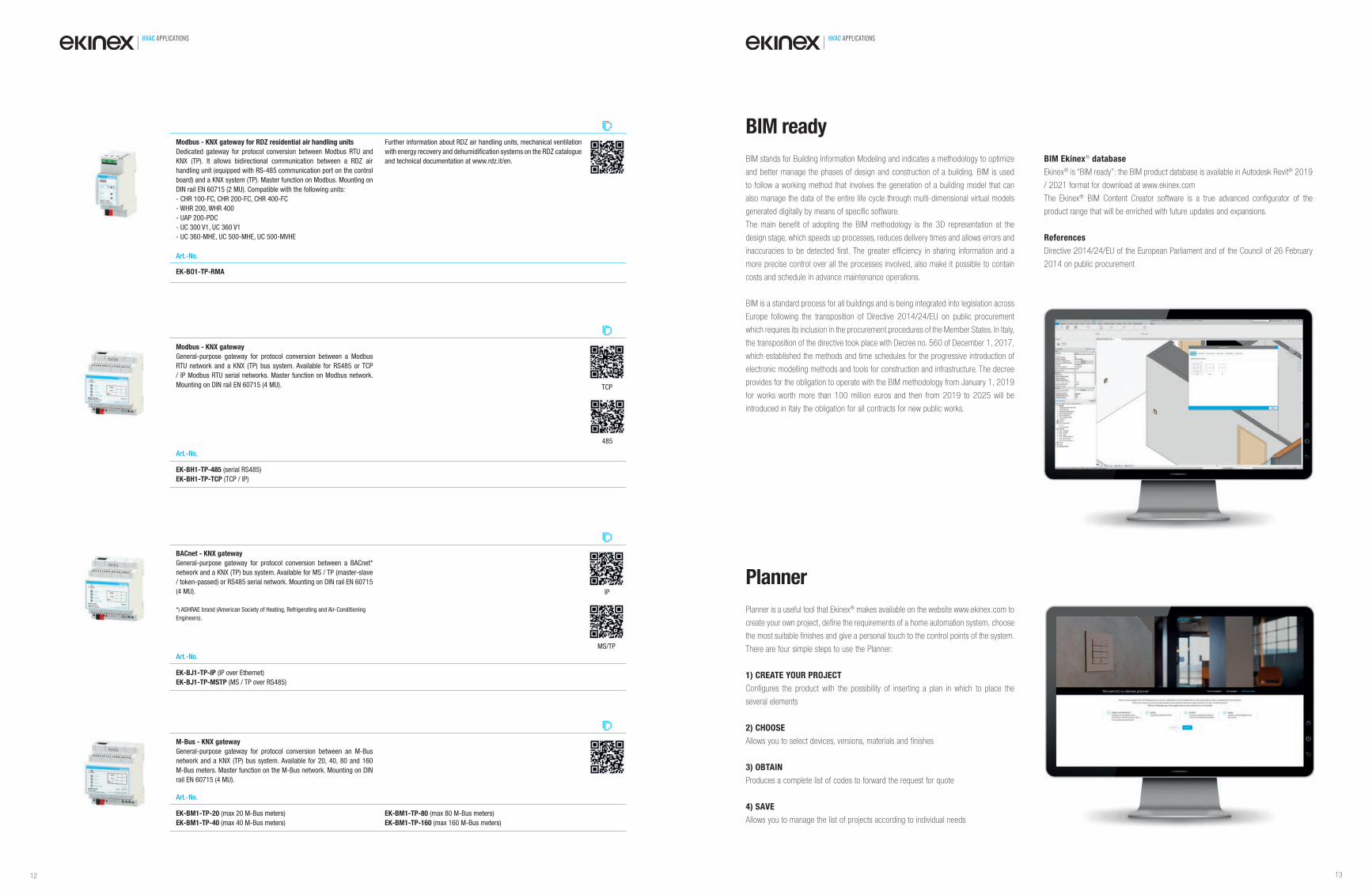
BACnet - KNX gateway
General-purpose gateway for protocol conversion between a BACnet*
network and a KNX (TP) bus system. Available for MS / TP (master-slave
/ token-passed) or RS485 serial network. Mounting on DIN rail EN 60715
(4 MU).
*) ASHRAE brand (American Society of Heating, Refrigerating and Air-Conditioning
Engineers).
MS/TP
IP
Art.-No.
EK-BJ1-TP-IP (IP over Ethernet)
EK-BJ1-TP-MSTP (MS / TP over RS485)
M-Bus - KNX gateway
General-purpose gateway for protocol conversion between an M-Bus
network and a KNX (TP) bus system. Available for 20, 40, 80 and 160
M-Bus meters. Master function on the M-Bus network. Mounting on DIN
rail EN 60715 (4 MU).
Art.-No.
EK-BM1-TP-20 (max 20 M-Bus meters)
EK-BM1-TP-40 (max 40 M-Bus meters)
EK-BM1-TP-80 (max 80 M-Bus meters)
EK-BM1-TP-160 (max 160 M-Bus meters)
Modbus - KNX gateway
General-purpose gateway for protocol conversion between a Modbus
RTU network and a KNX (TP) bus system. Available for RS485 or TCP
/ IP Modbus RTU serial networks. Master function on Modbus network.
Mounting on DIN rail EN 60715 (4 MU).
485
TCP
Art.-No.
EK-BH1-TP-485 (serial RS485)
EK-BH1-TP-TCP (TCP / IP)
BIM stands for Building Information Modeling and indicates a methodology to optimize
and better manage the phases of design and construction of a building. BIM is used
to follow a working method that involves the generation of a building model that can
also manage the data of the entire life cycle through multi-dimensional virtual models
generated digitally by means of specific software.
The main benefit of adopting the BIM methodology is the 3D representation at the
design stage, which speeds up processes, reduces delivery times and allows errors and
inaccuracies to be detected first. The greater efficiency in sharing information and a
more precise control over all the processes involved, also make it possible to contain
costs and schedule in advance maintenance operations.
BIM is a standard process for all buildings and is being integrated into legislation across
Europe following the transposition of Directive 2014/24/EU on public procurement
which requires its inclusion in the procurement procedures of the Member States. In Italy,
the transposition of the directive took place with Decree no. 560 of December 1, 2017,
which established the methods and time schedules for the progressive introduction of
electronic modelling methods and tools for construction and infrastructure. The decree
provides for the obligation to operate with the BIM methodology from January 1, 2019
for works worth more than 100 million euros and then from 2019 to 2025 will be
introduced in Italy the obligation for all contracts for new public works.
BIM ready
Planner is a useful tool that Ekinex® makes available on the website www.ekinex.com to
create your own project, define the requirements of a home automation system, choose
the most suitable finishes and give a personal touch to the control points of the system.
There are four simple steps to use the Planner:
1) CREATE YOUR PROJECT
Configures the product with the possibility of inserting a plan in which to place the
several elements
2) CHOOSE
Allows you to select devices, versions, materials and finishes
3) OBTAIN
Produces a complete list of codes to forward the request for quote
4) SAVE
Allows you to manage the list of projects according to individual needs
Planner
BIM Ekinex® database
Ekinex® is “BIM ready”: the BIM product database is available in Autodesk Revit® 2019
/ 2021 format for download at www.ekinex.com
The Ekinex® BIM Content Creator software is a true advanced configurator of the
product range that will be enriched with future updates and expansions.
References
Directive 2014/24/EU of the European Parliament and of the Council of 26 February
2014 on public procurement
Modbus - KNX gateway for RDZ residential air handling units
Dedicated gateway for protocol conversion between Modbus RTU and
KNX (TP). It allows bidirectional communication between a RDZ air
handling unit (equipped with RS-485 communication port on the control
board) and a KNX system (TP). Master function on Modbus. Mounting on
DIN rail EN 60715 (2 MU). Compatible with the following units:
- CHR 100-FC, CHR 200-FC, CHR 400-FC
- WHR 200, WHR 400
- UAP 200‐PDC
- UC 300 V1, UC 360 V1
- UC 360-MHE, UC 500-MHE, UC 500-MVHE
Further information about RDZ air handling units, mechanical ventilation
with energy recovery and dehumidifi cation systems on the RDZ catalogue
and technical documentation at www.rdz.it/en.
Art.-No.
EK-BO1-TP-RMA
12 13
HVAC APPLICATIONS
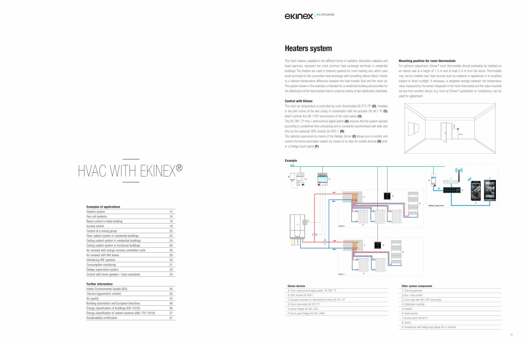
The room heaters, available in the different forms of radiators, decorative radiators and
towel warmers, represent the most common heat exchange terminals in residential
buildings. The heaters are used in hydronic systems for room heating only, which uses
small terminals for the convection heat exchange (with prevailing natural effect), thanks
to a relevant temperature difference between the heat transfer fluid and the room air.
The system shown in the example is intended for a residential building and provides for
the distribution of the heat transfer fluid to zones by means of two distribution manifolds.
Control with Ekinex
The room air temperature is controlled by room thermostats EK-E72-TP (D), installed
in the pilot rooms of the two zones, in combination with the actuator EK-HE1-TP (C)
which controls the ON / OFF servomotors of the zone valves (3).
The EK-TM1-TP time / astronomical digital switch (A) ensures that the system operate
according to predefined time scheduling and is constantly synchronised with date and
time by the (optional) GPS module EK-GPS-1 (B).
The optional supervision by means of the Delégo Server (E) allows you to monitor and
control the home automation system by means of an App for mobile devices (9) and/
or a Delégo touch-panel (F).
Mounting position for room thermostats
For optimum adjustment, Ekinex® room thermostats should preferably be installed on
an interior wall at a height of 1.5 m and at least 0.3 m from the doors. Thermostats
may not be installed near heat sources such as radiators or appliances or in locations
subject to direct sunlight. If necessary, a weighted average between the temperature
value measured by the sensor integrated in the room thermostat and the value received
via bus from another device (e.g. from an Ekinex® pushbutton or multisensor) can be
used for adjustment.
Ekinex devices
A) Time / astronomical digital switch EK-TM1-TP
B) GPS module EK-GPS-1
C) Actuator-controller for electrothermal drives EK-HE1-TP
D) Room thermostat EK-E72-TP
E) Server Delègo EK-DEL-SRV-...
F) Touch-panel Delégo EK-DEL-xPAN...
Other system components
1) Thermal generator
2) Run / stop contact
3) Zone valve with ON / OFF servomotor
4) Distribution manifold
5) Radiator
6) Towel warmer
7) Access point LAN Wi-Fi
8) Switch
9) Smartphone with Delégo App (Apple iOS or Android)
Heaters system
1,50 m
0,30
m
Examples of applications
Heaters system 15
Fan-coil systems 16
Room control in hotel building 18
Access control 19
Control of a mixing group 20
Floor radiant system in residential buildings 22
Ceiling radiant system in residential buildings 24
Ceiling radiant system in functional buildings 26
Air renewal with energy recovery ventilation units 28
Air renewal with VAV boxes 29
Interfacing VRF systems 30
Consumption monitoring 31
Delégo supervision system 32
Control with home speaker / voice assistants 33
Further information
Indoor Environmental Quality (IEQ) 34
Thermo-hygrometric comfort 35
Air quality 35
Building automation and European directives 36
Energy classification of buildings (EN 15232) 36
Energy classification of radiant systems (UNI / TR 11619) 37
Sustainability certification 37
HVAC WITH EKINEX®
Zon 1
Zon 2
EDig
K-itTalM
t1i-meTP
/ Astronomical switch
Line
Dev.
Area
bus KNX
1A
3 41 2 7 85 6
1B 2B2A
3A
11 129 10
3B 4A 4B
L N15 1613 14
L N
N
N
1
2
3
3
4
4
5
5
AB
C
D
D
IP
E
6
7 F
8
Supervision
9
6
R EK-DEL-SRVDelégo Server
Example
15
HVAC APPLICATIONS HVAC APPLICATIONS
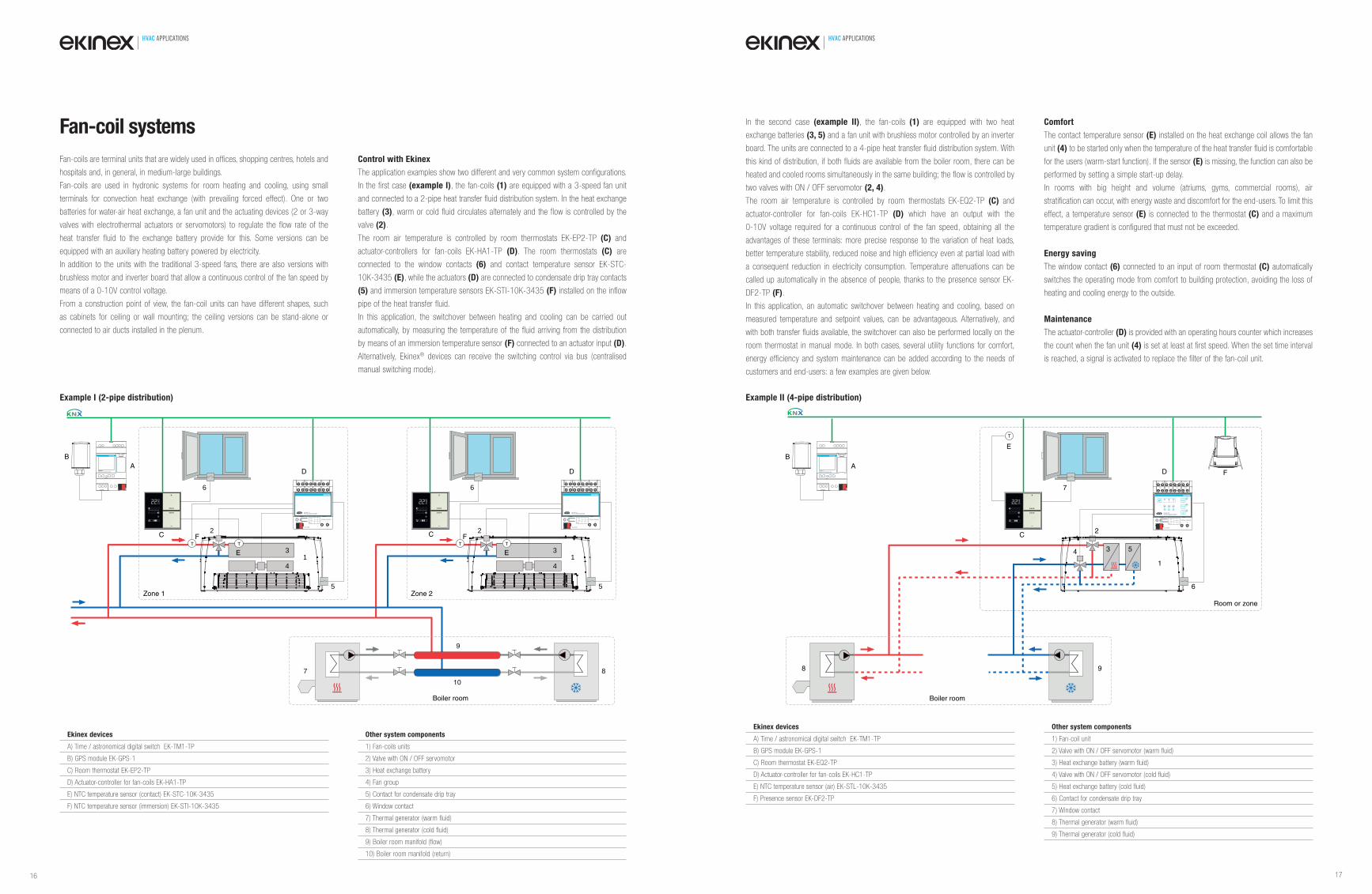
Ekinex devices
A) Time / astronomical digital switch EK-TM1-TP
B) GPS module EK-GPS-1
C) Room thermostat EK-EP2-TP
D) Actuator-controller for fan-coils EK-HA1-TP
E) NTC temperature sensor (contact) EK-STC-10K-3435
F) NTC temperature sensor (immersion) EK-STI-10K-3435
Other system components
1) Fan-coils units
2) Valve with ON / OFF servomotor
3) Heat exchange battery
4) Fan group
5) Contact for condensate drip tray
6) Window contact
7) Thermal generator (warm fluid)
8) Thermal generator (cold fluid)
9) Boiler room manifold (flow)
10) Boiler room manifold (return)
Fan-coils are terminal units that are widely used in offices, shopping centres, hotels and
hospitals and, in general, in medium-large buildings.
Fan-coils are used in hydronic systems for room heating and cooling, using small
terminals for convection heat exchange (with prevailing forced effect). One or two
batteries for water-air heat exchange, a fan unit and the actuating devices (2 or 3-way
valves with electrothermal actuators or servomotors) to regulate the flow rate of the
heat transfer fluid to the exchange battery provide for this. Some versions can be
equipped with an auxiliary heating battery powered by electricity.
In addition to the units with the traditional 3-speed fans, there are also versions with
brushless motor and inverter board that allow a continuous control of the fan speed by
means of a 0-10V control voltage.
From a construction point of view, the fan-coil units can have different shapes, such
as cabinets for ceiling or wall mounting; the ceiling versions can be stand-alone or
connected to air ducts installed in the plenum.
Control with Ekinex
The application examples show two different and very common system configurations.
In the first case (example I), the fan-coils (1) are equipped with a 3-speed fan unit
and connected to a 2-pipe heat transfer fluid distribution system. In the heat exchange
battery (3), warm or cold fluid circulates alternately and the flow is controlled by the
valve (2).
The room air temperature is controlled by room thermostats EK-EP2-TP (C) and
actuator-controllers for fan-coils EK-HA1-TP (D). The room thermostats (C) are
connected to the window contacts (6) and contact temperature sensor EK-STC-
10K-3435 (E), while the actuators (D) are connected to condensate drip tray contacts
(5) and immersion temperature sensors EK-STI-10K-3435 (F) installed on the inflow
pipe of the heat transfer fluid.
In this application, the switchover between heating and cooling can be carried out
automatically, by measuring the temperature of the fluid arriving from the distribution
by means of an immersion temperature sensor (F) connected to an actuator input (D).
Alternatively, Ekinex® devices can receive the switching control via bus (centralised
manual switching mode).
Fan-coil systems
2
13
4
5
IN1 4 3
C11 21
V1 V231 41
V351 61
DO171 81
IN2 7 85 6 9 01
1 2
L NDev.
Line
Area
bus KNX
230Vac-50/60Hz
R EK-HA1-TPFan-coil actuator/controller
6
9
10
7 8
T
2
13
4
5
IN1 4 3
C11 21
V1 V231 41
V351 61
DO171 81
IN2 7 85 6 9 01
1 2
L NDev.
Line
Area
bus KNX
230Vac-50/60Hz
R EK-HA1-TPFan-coil actuator/controller
6
T
EK-TM1-TPDigital time / Astronomical switch
AB
C C
D D
E E
Zone 1 Zone 2
T TFF
Boiler room
Example I (2-pipe distribution)
2
1
6
7
EK-TM1-TP
Digital time / Astronomical switch
A
B
C
D
IN14 3
C11 21
V1 V231 41
V351 61
DO171 81
DO2
IN26 5
IN38 7
0-10V9 01
1 2
L NDev.
Line
Area
bus KNX
-+
230Vac-50/60Hz
3 1
R
DO12
DO2
EK-HC1-TPFan-coil actuator/controller
34 5
T
E
8 9
Room or zone
F
Boiler room
Example II (4-pipe distribution)
In the second case (example II), the fan-coils (1) are equipped with two heat
exchange batteries (3, 5) and a fan unit with brushless motor controlled by an inverter
board. The units are connected to a 4-pipe heat transfer fluid distribution system. With
this kind of distribution, if both fluids are available from the boiler room, there can be
heated and cooled rooms simultaneously in the same building; the flow is controlled by
two valves with ON / OFF servomotor (2, 4).
The room air temperature is controlled by room thermostats EK-EQ2-TP (C) and
actuator-controller for fan-coils EK-HC1-TP (D) which have an output with the
0-10V voltage required for a continuous control of the fan speed, obtaining all the
advantages of these terminals: more precise response to the variation of heat loads,
better temperature stability, reduced noise and high efficiency even at partial load with
a consequent reduction in electricity consumption. Temperature attenuations can be
called up automatically in the absence of people, thanks to the presence sensor EK-
DF2-TP (F).
In this application, an automatic switchover between heating and cooling, based on
measured temperature and setpoint values, can be advantageous. Alternatively, and
with both transfer fluids available, the switchover can also be performed locally on the
room thermostat in manual mode. In both cases, several utility functions for comfort,
energy efficiency and system maintenance can be added according to the needs of
customers and end-users: a few examples are given below.
Comfort
The contact temperature sensor (E) installed on the heat exchange coil allows the fan
unit (4) to be started only when the temperature of the heat transfer fluid is comfortable
for the users (warm-start function). If the sensor (E) is missing, the function can also be
performed by setting a simple start-up delay.
In rooms with big height and volume (atriums, gyms, commercial rooms), air
stratification can occur, with energy waste and discomfort for the end-users. To limit this
effect, a temperature sensor (E) is connected to the thermostat (C) and a maximum
temperature gradient is configured that must not be exceeded.
Energy saving
The window contact (6) connected to an input of room thermostat (C) automatically
switches the operating mode from comfort to building protection, avoiding the loss of
heating and cooling energy to the outside.
Maintenance
The actuator-controller (D) is provided with an operating hours counter which increases
the count when the fan unit (4) is set at least at first speed. When the set time interval
is reached, a signal is activated to replace the filter of the fan-coil unit.
Ekinex devices
A) Time / astronomical digital switch EK-TM1-TP
B) GPS module EK-GPS-1
C) Room thermostat EK-EQ2-TP
D) Actuator-controller for fan-coils EK-HC1-TP
E) NTC temperature sensor (air) EK-STL-10K-3435
F) Presence sensor EK-DF2-TP
Other system components
1) Fan-coil unit
2) Valve with ON / OFF servomotor (warm fluid)
3) Heat exchange battery (warm fluid)
4) Valve with ON / OFF servomotor (cold fluid)
5) Heat exchange battery (cold fluid)
6) Contact for condensate drip tray
7) Window contact
8) Thermal generator (warm fluid)
9) Thermal generator (cold fluid)
16 17
HVAC APPLICATIONS HVAC APPLICATIONS
Accédo software suite
Software for the integrated management of technological systems,
particularly suitable for accommodation and hospitality structures (hotels,
residences, guest houses or bed & breakfasts). Client-server architecture
with HTML5 web server functionality. Programming of transponder cards
for access control, presence detection and (optional) electronic money
functionality. Automatic import of ETS projects with easy and intuitive
creation of graphic pages, drag&drop, advanced copy/paste and undo/
redo functions. Integrated management of calendars, scenarios and
schedules. Interface to other communication protocols such as BACnet,
Modbus, M-Bus, etc.
Requirements
- Operating system: Microsoft Windows® 7 or later (recommended:
Windows® 10). In a server environment, it is possible to use
Windows® Server 2016 (in its Essential, Standard, Professional or
Enterprise versions) can be used in a server environment or later -
RS232 I/O
- Processor: Intel Core i5 3.3 GHz or higher
- RAM memory: 4 GB minimum, 8 GB for server installation
- Hard drive: 40 GB minimum free for server installation
- SSD: 240 GB
- Monitor: Full HD
Nr. art.
EK-ACC-SW Transponder Supervisor Software EK-ACC-Lx Software licence for x readers (x = 12, 25, 50, 100, 200)
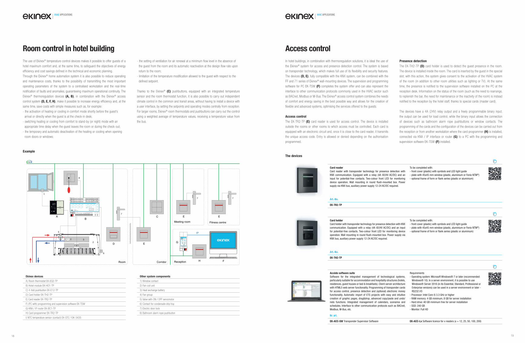
The use of Ekinex® temperature control devices makes it possible to offer guests of a
hotel maximum comfort and, at the same time, to safeguard the objectives of energy
efficiency and cost savings defined in the technical and economic planning.
Through the Ekinex® home automation system it is also possible to reduce operating
and maintenance costs, thanks to the possibility of transmitting the most important
operating parameters of the system to a centralised workstation and the real-time
notification of faults and anomalies, guaranteeing maximum operational continuity. The
Ekinex® thermoregulation devices (A, B), in combination with the Ekinex® access
control system (D, E, F, H), make it possible to increase energy efficiency and, at the
same time, save costs with simple measures such as, for example:
- the activation of heating or cooling in comfort mode shortly before the guest’s
arrival or directly when the guest is at the check-in desk;
- switching heating or cooling from comfort to stand-by (or night) mode with an
appropriate time delay when the guest leaves the room or during the check-out;
- the temporary and automatic deactivation of the heating or cooling when opening
room doors or windows;
- the setting of ventilation for air renewal at a minimum flow level in the absence of
the guest from the room and its automatic reactivation at the design flow rate upon
return to the room;
- limitation of the temperature modification allowed to the guest with respect to the
defined setpoint.
Thanks to the Ekinex® (C) pushbuttons, equipped with an integrated temperature
sensor and the room thermostat function, it is also possible to carry out independent
climate control in the common and transit areas, without having to install a device with
a user interface, by setting the setpoints and operating modes centrally from reception.
For larger rooms, Ekinex® room thermostats and pushbuttons can carry out the control
using a weighted average of temperature values, receiving a temperature value from
the bus.
AB
1
BO1 BO2 S
BO5 BO6
BO3
BO7 BO10
EK-HO1-TPRoom Hotel Controller
BO4 V1 V2 V3
TAEH8OB COOL BO9
L N
bus KNX 3 4 5 6 7 8 9 10 11 12 13 14 15 16 17 18 19 20 21 22 23 24 25 1 2
26 27 28 29 30 31 32 33 34 35 36 37 38 39 40 41
42 43 44 45 46 47 48 49 50 51 52 53 54 55 56 57
AI1
BO1
AI2/
BI2
BI3
BI4
BI5
BI6
BI7
BI8
BI9
CO
MBI
10BI
11BI
12C
OM
0..1
0VC
omC
om
BO2
BO3
BO4 COMV V1 V2 V3
12/2
4 Va
c
BO5
HEA
T
12/2
4 Va
c
CO
OL
230 Vac 50/60 Hz
BO6
BO7
BO8
BO9
BO10
L N
bus KNX 3 4 5 6 7 8 9 10 11 12 13 14 15 16 17 18 19 20 21 22 23 24 25 1 2
26 27 28 29 30 31 32 33 34 35 36 37 38 39 40 41
42 43 44 45 46 47 48 49 50 51 52 53 54 55 56 57
AI1/
BI1
BO1
AI2/
BI2
BI3
BI4
BI5
BI6
BI7
BI8
BI9
CO
MBI
10BI
11BI
12C
OM
0..1
0VC
omC
om
BO2
BO3
BO4 COMV V1 V2 V3
12/2
4 Va
c
BO5
HEA
T
12/2
4 Va
c
CO
OL
230 Vac 50/60 Hz
BO6
BO7
BO8
BO9
BO10
Dev.
Line
Area
5
2
6
T
D E4
3
C
I
7
E
Fitness centre
7
E
Meeting room
Reception
8
H
busstatus
traffic
GA
function
PA
R EK-BC1-TPIP router
IP TP
IP
F
G
Room Corridor
R
7
Room control in hotel building
Example
Ekinex devices
A) Room thermostat EK-EQ2-TP
B) Hotel module EK-HO1-TP
C) 4-fold pushbutton EK-E12-TP
D) Card holder EK-TH2-TP
E) Card reader EK-TR2-TP
F) (PC with) programming and supervision software EK-TSW
G) KNX / IP router EK-BC1-TP
H) Card programmer EK-TR2-TP
I) NTC temperature sensor (contact) EK-STC-10K-3435
Other system components
1) Window contact
2) Fan-coil unit
3) Heat exchange battery
4) Fan group
5) Valve with ON / OFF servomotor
6) Contact for condensate drip tray
7) Electric door lock
8) Bathroom alarm rope pushbutton
Access control
In hotel buildings, in combination with thermoregulation solutions, it is ideal the use of
the Ekinex® system for access and presence detection control. The system is based
on transponder technology, which makes full use of its flexibility and security features.
The devices (D, E), fully compatible with the KNX system, can be combined with the
FF and 71 series of Ekinex® wall-mounting devices. The supervision and programming
software for PC EK-TSW (F) completes the system offer and can also represent the
interface to other communication protocols commonly used in the HVAC sector such
as BACnet, Modbus or M-Bus. The Ekinex® access control system combines the needs
of comfort and energy saving in the best possible way and allows for the creation of
flexible and advanced systems, optimising the services offered to the guests.
Access control
The EK-TR2-TP (E) card reader is used for access control. The device is installed
outside the rooms or other rooms to which access must be controlled. Each card is
equipped with an electronic circuit and, once it is close to the card reader, it transmits
the unique access code. Entry is allowed or denied depending on the authorisation
programmed.
Presence detection
The EK-TH2-TP (D) card holder is used to detect the guest presence in the room.
The device is installed inside the room. The card is inserted by the guest in the special
slot; with this action, the system gives consent to the activation of the HVAC system
of the room (in addition to other room utilities such as lighting or TV). At the same
time, the presence is notified to the supervision software installed on the PC at the
reception desk. Information on the status of the room (such as the need to rearrange,
to replenish the bar, the need for maintenance or the inactivity of the room) is instead
notified to the reception by the hotel staff, thanks to special cards (master card).
The devices have a 4A (24V) relay output and a freely programmable binary input;
the output can be used for load control, while the binary input allows the connection
of devices such as bathroom alarm rope pushbuttons or window contacts. The
programming of the cards and the configuration of the devices can be carried out from
the reception or from another workstation where the card programmer (H) is installed,
connected via KNX / IP interface or router (G) to a PC with the programming and
supervision software EK-TSW (F) installed.
Card holder
Card holder with transponder technology for presence detection with KNX
communication. Equipped with a relay (4A @24V AC/DC) and an input
for potential-free contacts. Two-colour front LED for monitoring device
operation. Wall mounting in round fl ush-mounted box. Power supply via
KNX bus, auxiliary power supply 12-24 AC/DC required.
To be completed with:
- front cover (plastic) with symbols and LED light guide
- plate with 45x45 mm window (plastic, aluminium or Fenix NTM®)
- optional frame of form or fl ank series (plastic or aluminium)
Art.-No.
EK-TH2-TP
The devices
Card reader
Card reader with transponder technology for presence detection with
KNX communication. Equipped with a relay (4A @24V AC/DC) and an
input for potential-free contacts. Two-colour front LED for monitoring
device operation. Wall mounting in round fl ush-mounted box. Power
supply via KNX bus, auxiliary power supply 12-24 AC/DC required.
To be completed with:
- front cover (plastic) with symbols and LED light guide
- plate with 45x45 mm window (plastic, aluminium or Fenix NTM®)
- optional frame of form or fl ank series (plastic or aluminium)
Art.-No.
EK-TR2-TP
18 19

HVAC APPLICATIONS HVAC APPLICATIONS
More and more often in systems designed for room heating, cooling and ventilation
there are simultaneously heat exchange, air handling or air renewal terminals with
different operating principles (such as radiators, radiant floor or ceiling panels, fan-coils,
dehumidifiers, mechanical ventilation units with integration of the sensible contribution
for cooling, etc.) that make it necessary to produce heat transfer fluid at different
temperatures. This can be done directly in the boiler room or locally, by controlling a
mixing group.
Control with Ekinex
The unmixed zone directly serves the heat exchange terminals with heat transfer fluid
at the temperature produced in the boiler room. The EK-HH1-TP unit (A) controls
the mixing group (1) by adjusting the flow temperature of the heat transfer fluid for
the mixed zone. For this purpose, the mixing valve (2) equipped with a servomotor
and the circulating pump (3) of the mixed zone are controlled, measuring the flow
temperature by means of an immersion sensor (C). Optionally, it is also possible to
measure the return temperature by means of a second immersion sensor (D). The
outdoor temperature sensor (B) measures the outdoor air temperature for climate
compensation control.
In the case of radiant panel systems also used for summer cooling, the ideal use of
the controller (A) is in combination with a maximum of 16 room thermostats EK-
EQ2-TP equipped with temperature and relative humidity sensors to have an effective
integration between the boiler room regulation (primary) and the room or zone control
(secondary).
In this way, the system on and off as well as the optimal flow temperature of the heat
transfer fluid are automatically selected according to the actual internal conditions of
the building; in cooling mode it is also possible to select the optimal flow temperature
with active protection from condensation.
Control of a mixing group
Control options Heating Cooling
Fixed point √ √
Climatic compensation √ √
Adjusting to internal conditions √ -
Adjusting to return temperature √ -
Climatic compensation and adjusting to internal conditions √ -
Adjusting to internal thermo-hygrometric conditions - √
Climatic compensation and adjusting to internal thermo-hygrometric conditions - √
6
7 8
A
2
4
3 1
T
Unmixed
15 16POWER AUX
3 4IN1 5 6IN2 7 8IN3
20 21DO1 22 23DO2 24 25DO3
9 10IN4 11 12IN5 13 14AO1
17 18 19OPENCLOSE COM
1 2
L N
bus KNX
EK-HH1-TPMixing group controller
OK
ESC
+ -
Dev.
Line
Area
T
5
B
CD
zoneMixedzone
Mixing substation
Boiler room
Example
Ekinex devices
A) Mixing group controller EK-HH1-TP
B) NTC temperature sensor (external) EK-STE-10K-3435
C) NTC temperature sensor (immersion) EK-STI-10K-3435
D) NTC temperature sensor (immersion) EK-STI-10K-3435
Other system components
1) Mixing group
2) Mixing valve with servomotor
3) Circulating pump (mixed zone)
4) Circulating pump (unmixed zone)
5) Boiler room manifold (flow)
6) Boiler room manifold (return)
7) Thermal generator (warm fluid)
8) Thermal generator (cold fluid)
Focus on the EK-HH1-TP mixing group controller
The EK-HH1-TP controller (A) is a KNX device, fully programmable via ETS, which
allows the flow temperature of the heat transfer fluid to be regulated in heating and
cooling hydronic systems.
The device can be used as a stand-alone unit or in combination with one or more
Ekinex® room thermostats to create single-zone or multi-zone systems (up to a
maximum of 16 zones), controlling the servomotor of a 3-point floating mixing valve,
powered at 230 Vac or 24 Vac, or with 0-10V signal and controlling the circulating
pump of the mixed circuit in run / stop mode. The device manages over-temperature
(in heating) and under-temperature (in cooling) alarms.
The controller has a backlit LCD text display, four membrane buttons for navigating
through the display menu and two LEDs for alarms and switching to manual mode.
The display allows the operating parameters to be monitored; some control parameters
can also be modified with respect to the initial configuration carried out with ETS.
The switchover of the system conduction mode (heating / cooling) can be done from
the bus, from a digital input (configured for this purpose) or manually from the front
keyboard. Alarms from anti-condensation probes can be managed.
The digital outputs, not used to activate a circulating pump, can be configured to
control a zone valve servomotor located on a circuit dedicated to fan-coil units or
dehumidifiers.
To create automation logic, the device is also equipped with 2-channel logic functions
(16 inputs per channel) with exclusive AND, OR, NOT and OR blocks and delayed
activation of the corresponding output.
Terminal no. Label Connection
3-4 IN1 Input 1 (fl ow temperature sensor)
5-6 IN2 Input 2 (return temperature sensor)
7-8 IN3 Input 3 (outdoor temperature sensor)
9-10 IN4 Input 4 (confi gurable as AI or DI)
11-12 IN5 Input 5 (confi gurable as AI or DI)
13-14 AO1 0-10 V control output for servomotor
15-16 POWER AUX TRIAC power supply (230 Vac o 24 Vac)
17 CLOSE Control output for servomotor (closing)
18 COM Control output for servomotor (common)
19 OPEN Control output for servomotor (opening)
20-21 DO1 Uscita a relè comando circolatore
22-23 DO2 Relais output (additional functions)
24-25 DO3 Relais output (additional functions)
Inputs and outputs
Switching the seasonal conduction mode
The seasonal (heating / cooling) mode can be switched in three ways:
- from the KNX bus;
- via the front keypad of the controller;
- by means of a switch connected to an input of the controller.
If switching from the KNX bus is selected, the controller receives the conduction mode
from another bus device (via a communication object), such as an Ekinex® room
thermostat, which has been assigned the master function for seasonal switching.
Switching can be carried out manually using the keypad and the display on the front of
the device: in this case, it is the EK-HH1-TP controller that performs the master function
of seasonal switching for all Ekinex® devices (sensors, actuators) that are on the same
system or part of a system served by the controller.
Switching via a switch connected to input IN5 (configured as DI) is suitable for stand-
alone applications in which there is no need for integration between the boiler room
(primary adjustment) and the rooms or zones (secondary adjustment). The switch can
be the same as the external selector used in the boiler room for switching the operation
of heat generators or shut-off valves of fluids.
The current operating mode is stored in the non-volatile memory of the controller.
Activating the mixing group
The mixing group can be activated in three ways:
- from the KNX bus;
- from a controller input;
- from a controller input and the KNX bus.
By selecting the activation from the KNX bus, the controller connects in logical OR the
flow requests coming from a maximum of 16 Ekinex® room thermostats. To activate the
mixing group it is sufficient that a single room thermostat requires flow.
The activation from an input is suitable for stand-alone applications in which there is
no need for integration between the boiler room (primary adjustment) and the rooms
or zones (secondary adjustment). A time programmer can be connected to input IN4
to activate the group according to scheduled time slots or the request of a stand-
alone room thermostat. In systems with distribution manifolds, the limit switches of the
electrothermal drives mounted on the individual valves can be connected in parallel.
An intermediate solution, on the other hand, involves activation both from the binary
input and from the KNX bus. The input can have priority over the flow requests coming
from the zones via bus (for example an external time zone programming device) or it
behaves as an additional zone (without priority).
In all cases it is possible to set an activation delay (from 1 to 255 seconds) for the
start of mixing; in fact, it is advisable to wait for the electrothermal drives to bring the
valves into the open position to prevent the circulating pump from exerting pressure on
hydraulically closed circuits.
20 21
HVAC APPLICATIONS HVAC APPLICATIONS
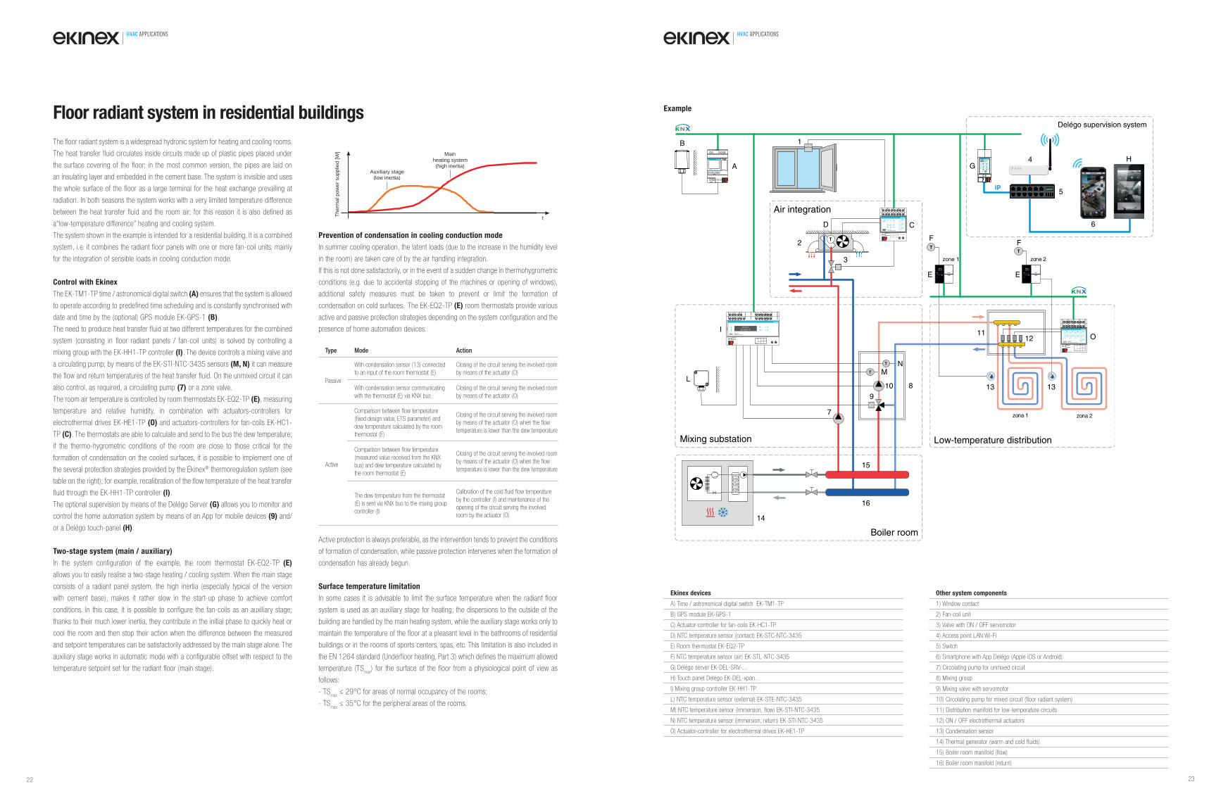
The floor radiant system is a widespread hydronic system for heating and cooling rooms.
The heat transfer fluid circulates inside circuits made up of plastic pipes placed under
the surface covering of the floor; in the most common version, the pipes are laid on
an insulating layer and embedded in the cement base. The system is invisible and uses
the whole surface of the floor as a large terminal for the heat exchange prevailing at
radiation. In both seasons the system works with a very limited temperature difference
between the heat transfer fluid and the room air; for this reason it is also defined as
a“low-temperature difference” heating and cooling system.
The system shown in the example is intended for a residential building. It is a combined
system, i.e. it combines the radiant floor panels with one or more fan-coil units, mainly
for the integration of sensible loads in cooling conduction mode.
Control with Ekinex
The EK-TM1-TP time / astronomical digital switch (A) ensures that the system is allowed
to operate according to predefined time scheduling and is constantly synchronised with
date and time by the (optional) GPS module EK-GPS-1 (B).
The need to produce heat transfer fluid at two different temperatures for the combined
system (consisting in floor radiant panels / fan-coil units) is solved by controlling a
mixing group with the EK-HH1-TP controller (I). The device controls a mixing valve and
a circulating pump; by means of the EK-STI-NTC-3435 sensors (M, N) it can measure
the flow and return temperatures of the heat transfer fluid. On the unmixed circuit it can
also control, as required, a circulating pump (7) or a zone valve.
The room air temperature is controlled by room thermostats EK-EQ2-TP (E), measuring
temperature and relative humidity, in combination with actuators-controllers for
electrothermal drives EK-HE1-TP (O) and actuators-controllers for fan-coils EK-HC1-
TP (C). The thermostats are able to calculate and send to the bus the dew temperature;
if the thermo-hygrometric conditions of the room are close to those critical for the
formation of condensation on the cooled surfaces, it is possible to implement one of
the several protection strategies provided by the Ekinex® thermoregulation system (see
table on the right); for example, recalibration of the flow temperature of the heat transfer
fluid through the EK-HH1-TP controller (I).
The optional supervision by means of the Delégo Server (G) allows you to monitor and
control the home automation system by means of an App for mobile devices (9) and/
or a Delégo touch-panel (H).
Two-stage system (main / auxiliary)
In the system configuration of the example, the room thermostat EK-EQ2-TP (E)
allows you to easily realise a two-stage heating / cooling system. When the main stage
consists of a radiant panel system, the high inertia (especially typical of the version
with cement base), makes it rather slow in the start-up phase to achieve comfort
conditions. In this case, it is possible to configure the fan-coils as an auxiliary stage;
thanks to their much lower inertia, they contribute in the initial phase to quickly heat or
cool the room and then stop their action when the difference between the measured
and setpoint temperatures can be satisfactorily addressed by the main stage alone. The
auxiliary stage works in automatic mode with a configurable offset with respect to the
temperature setpoint set for the radiant floor (main stage).
Prevention of condensation in cooling conduction mode
In summer cooling operation, the latent loads (due to the increase in the humidity level
in the room) are taken care of by the air handling integration.
If this is not done satisfactorily, or in the event of a sudden change in thermohygrometric
conditions (e.g. due to accidental stopping of the machines or opening of windows),
additional safety measures must be taken to prevent or limit the formation of
condensation on cold surfaces. The EK-EQ2-TP (E) room thermostats provide various
active and passive protection strategies depending on the system configuration and the
presence of home automation devices.
Active protection is always preferable, as the intervention tends to prevent the conditions
of formation of condensation, while passive protection intervenes when the formation of
condensation has already begun.
Surface temperature limitation
In some cases it is advisable to limit the surface temperature when the radiant floor
system is used as an auxiliary stage for heating; the dispersions to the outside of the
building are handled by the main heating system, while the auxiliary stage works only to
maintain the temperature of the floor at a pleasant level in the bathrooms of residential
buildings or in the rooms of sports centers, spas, etc. This limitation is also included in
the EN 1264 standard (Underfloor heating, Part 3) which defines the maximum allowed
temperature (TSmax
) for the surface of the floor from a physiological point of view as
follows:
- TSmax
≤ 29°C for areas of normal occupancy of the rooms;
- TSmax
≤ 35°C for the peripheral areas of the rooms.
Floor radiant system in residential buildings
Mainheating system (high inertia)
Auxiliary stage (low inertia)
Ther
mal
pow
er s
uppl
ied
[W]
t
T
T
T
T
T
zone 2zone 1
zona 1 zona 2
Boiler room
Low-temperature distributionMixing substation
Air integration
A
B
CD
E E
FF
I
LM
N
O
1
2
3
7
8
9
10
1112
13 13
14
15
16
IP
Delégo supervision system
G4
5
6
Example
Ekinex devices
A) Time / astronomical digital switch EK-TM1-TP
B) GPS module EK-GPS-1
C) Actuator-controller for fan-coils EK-HC1-TP
D) NTC temperature sensor (contact) EK-STC-NTC-3435
E) Room thermostat EK-EQ2-TP
F) NTC temperature sensor (air) EK-STL-NTC-3435
G) Delégo server EK-DEL-SRV-...
H) Touch panel Delégo EK-DEL-xpan...
I) Mixing group controller EK-HH1-TP
L) NTC temperature sensor (external) EK-STE-NTC-3435
M) NTC temperature sensor (immersion, flow) EK-STI-NTC-3435
N) NTC temperature sensor (immersion, return) EK-STI-NTC-3435
O) Actuator-controller for electrothermal drives EK-HE1-TP
Other system components
1) Window contact
2) Fan-coil unit
3) Valve with ON / OFF servomotor
4) Access point LAN Wi-Fi
5) Switch
6) Smartphone with App Delégo (Apple iOS or Android)
7) Circolating pump for unmixed circuit
8) Mixing group
9) Mixing valve with servomotor
10) Circolating pump for mixed circuit (floor radiant system)
11) Distribution manifold for low-temperature circuits
12) ON / OFF electrothermal actuators
13) Condensation sensor
14) Thermal generator (warm and cold fluids)
15) Boiler room manifold (flow)
16) Boiler room manifold (return)
Type Mode Action
Passive
With condensation sensor (13) connected
to an input of the room thermostat (E)
Closing of the circuit serving the involved room
by means of the actuator (O)
With condensation sensor communicating
with the thermostat (E) via KNX bus
Closing of the circuit serving the involved room
by means of the actuator (O)
Active
Comparison between fl ow temperature
(fi xed design value, ETS parameter) and
dew temperature calculated by the room
thermostat (E)
Closing of the circuit serving the involved room
by means of the actuator (O) when the fl ow
temperature is lower than the dew temperature
Comparison between fl ow temperature
(measured value received from the KNX
bus) and dew temperature calculated by
the room thermostat (E)
Closing of the circuit serving the involved room
by means of the actuator (O) when the fl ow
temperature is lower than the dew temperature
The dew temperature from the thermostat
(E) is sent via KNX bus to the mixing group
controller (I)
Calibration of the cold fl uid fl ow temperature
by the controller (I) and maintenance of the
opening of the circuit serving the involved
room by the actuator (O)
22 23
HVAC APPLICATIONS HVAC APPLICATIONS
The ceiling radiant system is a hydronic system for room heating and cooling, which
was added to the floor version over time; in common it maintains the characteristic
of having a low temperature difference between the heat transfer fluid and the room
air. The heat transfer fluid circulates inside circuits made up of metal or plastic pipes
integrated in a suspended false ceiling; the series of panels are fed by distribution
manifolds installed above the circuits served. In residential applications, the false ceiling
has a plasterboard finish towards the rooms, suitable for civil buildings, and an insulation
layer towards the top. The system is invisible and uses the whole surface of the ceiling
as a large terminal for the thermal exchange prevailing at radiation. As in the case of the
floor radiant system, the ceiling radiant panels only handle the heat loads of a sensible
type; in general, the ceiling solution offers a higher yield in cooling.
The radiant ceiling system shown in the example is used to heat and cool the rooms
of a residential building. This particular system is a combined system; it combines the
ceiling radiant panels with one or more units for energy recovery ventilation (ERV),
whose basic function is the renewal of the room air with high efficiency heat recovery.
In this case, moreover, they are complete machines for the air handling of the rooms,
able to support the operation of the system in summer cooling, also performing the
functions of dehumidification (with reduction of the cooling latent load) and handling of
part of the sensible cooling load.
Usually these machines do not serve a single room, but several rooms or an area of
a building. In the residential sector, for example, it is common to use one machine for
the living zone and a second one for the night zone. The installation is typically made
in a central position with respect to the served zone, for example recessed in the false
ceiling in the hallway or in the corridor.
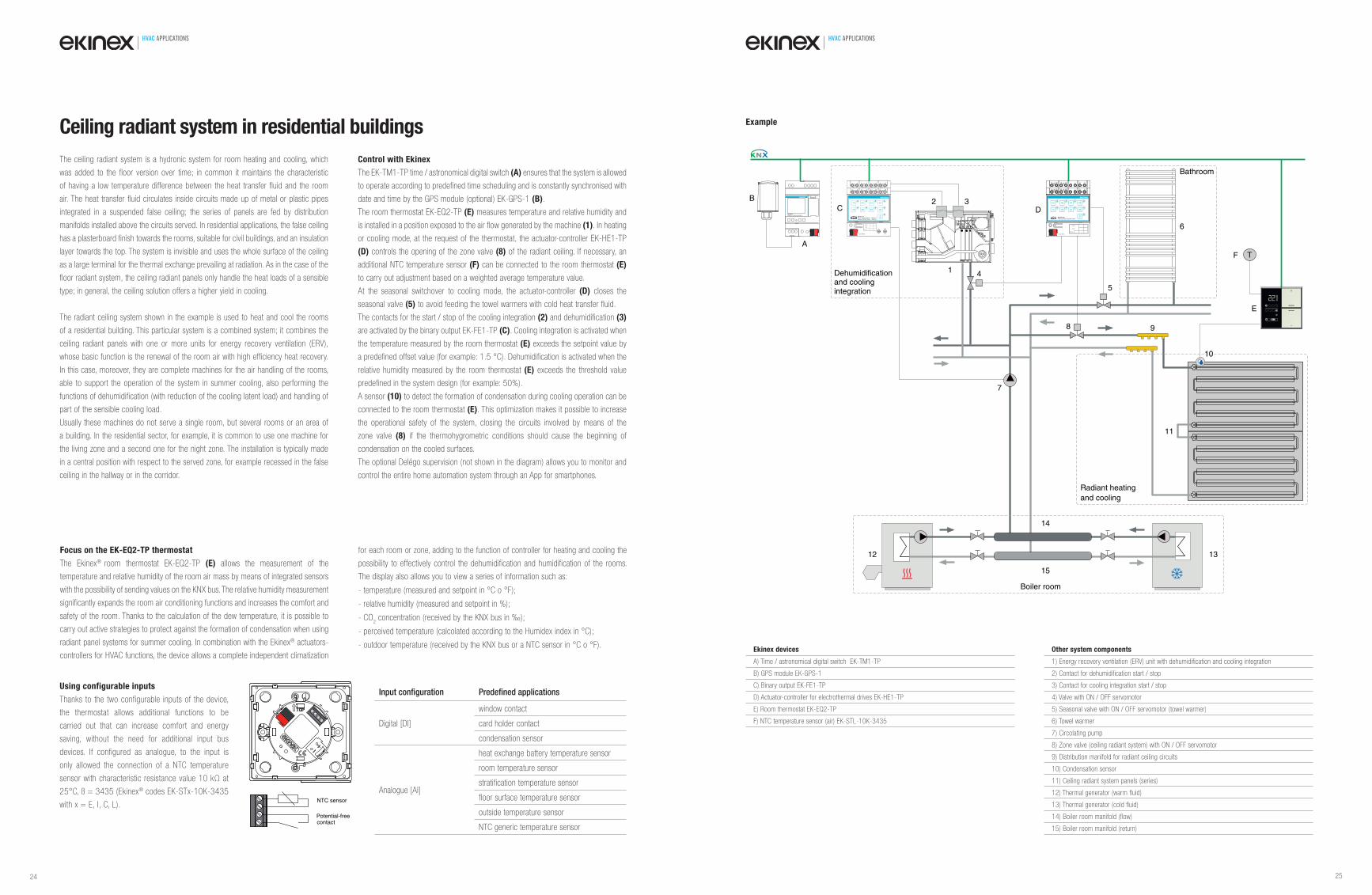
Control with Ekinex
The EK-TM1-TP time / astronomical digital switch (A) ensures that the system is allowed
to operate according to predefined time scheduling and is constantly synchronised with
date and time by the GPS module (optional) EK-GPS-1 (B).
The room thermostat EK-EQ2-TP (E) measures temperature and relative humidity and
is installed in a position exposed to the air flow generated by the machine (1). In heating
or cooling mode, at the request of the thermostat, the actuator-controller EK-HE1-TP
(D) controls the opening of the zone valve (8) of the radiant ceiling. If necessary, an
additional NTC temperature sensor (F) can be connected to the room thermostat (E)
to carry out adjustment based on a weighted average temperature value.
At the seasonal switchover to cooling mode, the actuator-controller (D) closes the
seasonal valve (5) to avoid feeding the towel warmers with cold heat transfer fluid.
The contacts for the start / stop of the cooling integration (2) and dehumidification (3)
are activated by the binary output EK-FE1-TP (C). Cooling integration is activated when
the temperature measured by the room thermostat (E) exceeds the setpoint value by
a predefined offset value (for example: 1.5 °C). Dehumidification is activated when the
relative humidity measured by the room thermostat (E) exceeds the threshold value
predefined in the system design (for example: 50%).
A sensor (10) to detect the formation of condensation during cooling operation can be
connected to the room thermostat (E). This optimization makes it possible to increase
the operational safety of the system, closing the circuits involved by means of the
zone valve (8) if the thermohygrometric conditions should cause the beginning of
condensation on the cooled surfaces.
The optional Delégo supervision (not shown in the diagram) allows you to monitor and
control the entire home automation system through an App for smartphones.
Ceiling radiant system in residential buildings
EK-TM1-TPDigital time / Astronomical switch
A
B
Dev.
Line
Area
bus KNX
1A
3 41 2 7 85 6
1B 2A 2B
3A
11 219 01
3B 4A 4B
L N51 6131 41
L N
N
N
C 1B 2B 3B 4B
1A 2A 3A 4A
EK-FE1-TP8xD.O. 16(10)A/230Vac ~ 50/60 Hz 4xBlind 16(10)A/230Vac ~ 50/60 Hz
3 41A
5 62A
7 83A
9 104A
11 121B
13 142B
15 163B
17 184B
1 2
L N
bus KNX
Dev.
Line
Area
D
E
1
2 3
4
5
6
7
8 9
10
11
12 13
14
15
TF
Boiler room
Dehumidificationand coolingintegration
Radiant heating and cooling
Bathroom
Example
Ekinex devices
A) Time / astronomical digital switch EK-TM1-TP
B) GPS module EK-GPS-1
C) Binary output EK-FE1-TP
D) Actuator-controller for electrothermal drives EK-HE1-TP
E) Room thermostat EK-EQ2-TP
F) NTC temperature sensor (air) EK-STL-10K-3435
Other system components
1) Energy recovery ventilation (ERV) unit with dehumidification and cooling integration
2) Contact for dehumidification start / stop
3) Contact for cooling integration start / stop
4) Valve with ON / OFF servomotor
5) Seasonal valve with ON / OFF servomotor (towel warmer)
6) Towel warmer
7) Circolating pump
8) Zone valve (ceiling radiant system) with ON / OFF servomotor
9) Distribution manifold for radiant ceiling circuits
10) Condensation sensor
11) Ceiling radiant system panels (series)
12) Thermal generator (warm fluid)
13) Thermal generator (cold fluid)
14) Boiler room manifold (flow)
15) Boiler room manifold (return)
Using configurable inputs
Thanks to the two configurable inputs of the device,
the thermostat allows additional functions to be
carried out that can increase comfort and energy
saving, without the need for additional input bus
devices. If configured as analogue, to the input is
only allowed the connection of a NTC temperature
sensor with characteristic resistance value 10 kΩ at
25°C, ß = 3435 (Ekinex® codes EK-STx-10K-3435
with x = E, I, C, L).
Input confi guration Predefi ned applications
Digital [DI]
window contact
card holder contact
condensation sensor
Analogue [AI]
heat exchange battery temperature sensor
room temperature sensor
stratification temperature sensor
floor surface temperature sensor
outside temperature sensor
NTC generic temperature sensor
Focus on the EK-EQ2-TP thermostat
The Ekinex® room thermostat EK-EQ2-TP (E) allows the measurement of the
temperature and relative humidity of the room air mass by means of integrated sensors
with the possibility of sending values on the KNX bus. The relative humidity measurement
significantly expands the room air conditioning functions and increases the comfort and
safety of the room. Thanks to the calculation of the dew temperature, it is possible to
carry out active strategies to protect against the formation of condensation when using
radiant panel systems for summer cooling. In combination with the Ekinex® actuators-
controllers for HVAC functions, the device allows a complete independent climatization
for each room or zone, adding to the function of controller for heating and cooling the
possibility to effectively control the dehumidification and humidification of the rooms.
The display also allows you to view a series of information such as:
- temperature (measured and setpoint in °C o °F);
- relative humidity (measured and setpoint in %);
- CO2 concentration (received by the KNX bus in ‰);
- perceived temperature (calcolated according to the Humidex index in °C);
- outdoor temperature (received by the KNX bus or a NTC sensor in °C o °F).
NTC sensor
Potential-freecontact
24 25

HVAC APPLICATIONS HVAC APPLICATIONS
The ceiling radiant panel system is widely used in offices and, more generally, in large
functional buildings such as hospitals, shopping malls, schools, universities, airports or
stations.
In these cases, the suspended ceiling is made up of metal panels (7) that can be
inspected completely similar to those usually used in these buildings, but with hydronic
circuits applied to the upper part and possibly an insulating layer towards the plenum.
The hydronic circuits consist of metal or plastic pipes and metal thermal diffusers that
exchange heat between the pipes and the metal surface of the false ceiling.
The series of radiant panels are powered by distribution manifolds installed above the
circuits served. The system is invisible and uses the entire surface of the ceiling as a
large terminal for the heat exchange (prevailing as radiation). As in the case of the floor
system, the ceiling radiant panels only handle the sensible heat loads; in general, the
ceiling solution offers a higher yield in cooling.
The ceiling radiant system shown in the example is used for heating and cooling the
rooms of a functional building. The distribution is made with a 4-pipe system that make
available both fluids at the same time to heat or cool the room. This type of distribution
can be advantageous when it is expected that the thermal loads can vary greatly during
the same day or depending on the different exposures of the building.
In this application, the air renewal and dehumidification functions are performed by a
system with air centrally treated by an air handling unit and distributed in the rooms by
means of ducted systems and diffusers. As an alternative to the diffusers, and in the
absence of insulation towards the plenum, the microperforation present on the metal
panels can be used for the diffusion of renewal and dehumidified air in the rooms.
Control with Ekinex
The room air temperature is controlled in each zone or room by means of an EK-ET2-TP
(F) multisensor in combination with the EK-HE1-TP actuator-controller (C) that controls
the servomotors of the zone valves that regulate the flow of hot or cold heat transfer
fluid to the series of radiant panels. Thanks to the relative humidity measurement, the
multisensor (F) is also able to calculate the dew temperature and send it via bus to
higher level systems (BMS) through appropriate gateways.
Where necessary, the multisensor (F) can receive a measured temperature value
from an Ekinex® pushbutton (E), normally used to control other bus functions such as
lighting or shading, to control with a weighted temperature value. This can typically be
done in large or high rooms, where the temperature value measured by the multisensor
is not fully significant of the general temperature conditions in the room.
The input interface EK-CD2-TP (H) provides for the acquisition of signals from
condensation sensors (5) and window contacts (6). The condensation sensor (5) is
installed in contact with the first heat exchange element served by the hydronic circuits
in order to timely detect the possible formation of condensation when the cooling
mode is active and let the actuator-controller (C) close the zone valve (4), bringing
the system to safety.
To reduce energy consumption, the operating mode can be automatically switched
when detecting the absence of people within the zone using the EK-DF2-TP presence
sensor (G), recalling temperature attenuations of an opposite sign in the heating and
cooling conduction modes.
Ceiling radiant system in functional buildings
Low-temperaturedistribution
7
Boiler room
6
8
3
1
C
9
4
3
1
4
3
2
4
3
2
4
6
D H
zone 1
A
B
7
5
zone 2
7
5
F
zone 2
EG
F
zone 1
EG
Example
Ekinex devices
A) Time / astronomical digital switch EK-TM1-TP
B) GPS module EK-GPS-1
C) Actuator-controller for electrothermal drives EK-HE1-TP
D) Touch&See display EK-EC2-TP
E) 4-fold pushbutton (8 functions) EK-E12-TP
F) Multisensor EK-ET2-TP
G) Presence sensor EK-DF2-TP
H) Universal interface EK-CD2-TP
Other system components
1) Distribution manifold for low temperature circuits (flow)
2) Distribution manifold for low temperature circuits (return)
3) Valve with ON / OFF servomotor (warm fluid)
4) Valve with ON / OFF servomotor (cold fluid)
5) Condensation sensor
6) Window contact
7) Ceiling radiant panels (series)
8) Thermal generator (warm fluid)
9) Thermal generator (cold fluid)
LEDs
The eight integrated LEDs (with light
guide), positioned on the sides of
the front cover, can be configured to
indicate the active operating mode of the
heating system (heating or cooling), the
concentration of CO2 (equivalent) and
TVOC (only for EK-ES2-TP version) and
the activation of the dehumidification or
humidification function.
Focus on the multisensor
The Ekinex® multisensor (F) is a complete device for controlling indoor room comfort
that combines many functions usually distributed among several sensors and different
controllers. The device measures temperature, relative humidity and air quality
(parameters: TVOC concentration in ppb and/or equivalent CO2 concentration in ppm)
using the integrated sensors, with the possibility of sending values to the KNX bus, and
can also act as a controller for each of the measured parameters. With a single compact
device it is therefore possible to control both the thermohygrometric conditions and the
quality of the room air mass.
In special cases (large or high rooms, in the presence of strong asymmetry in the
temperature distribution or when the device is installed in an unsuitable position),
the room air temperature can be controlled by using a weighted average between
two temperature values: the first measured by the integrated sensor and the second
received by the KNX bus. Two independent thresholds for relative humidity and
three thresholds for CO2 and TVOC concentration can be configured. To implement
automation logic, combinatorial functions such as AND, OR, NOT and exclusive OR are
available; thanks to these functions, it is possible to use the information available on the
home automation system to control air renewal according to the actual need (DCV or
Demand Controlled Ventilation).
Versions
EK-ET2-TP with temperature, relative humidity and CO2 eq. measurement
EK-ES2-TP with temperature, relative humidity, TVOC and CO2 eq. measurement
LED Colour and meaning (EK-ES2-TP version)
1 white (heating mode) or red (heating ON)
2 white (cooling mode) or blue (cooling ON)
3 blue (dehumidification ON)
4 green (humidification ON)
5red blinking (CO
2 eq. concentration > threshold 3)
orange (CO2 eq. concentration between thresholds 2 and 3)
6yellow (CO
2 eq. concentration between thresholds 1 and 2)
green (CO2 eq. concentration < threshold 1)
7red blinking lampeggiante (TVOC concentration > threshold 3)
orange (TVOC concentration between thresholds 2 and 3)
8yellow (TVOC concentration between thresholds 1 and 2)
green (TVOC concentration < threshold 1)
1
2
3
4
1
2
3
4
5
6
7
8
26 27
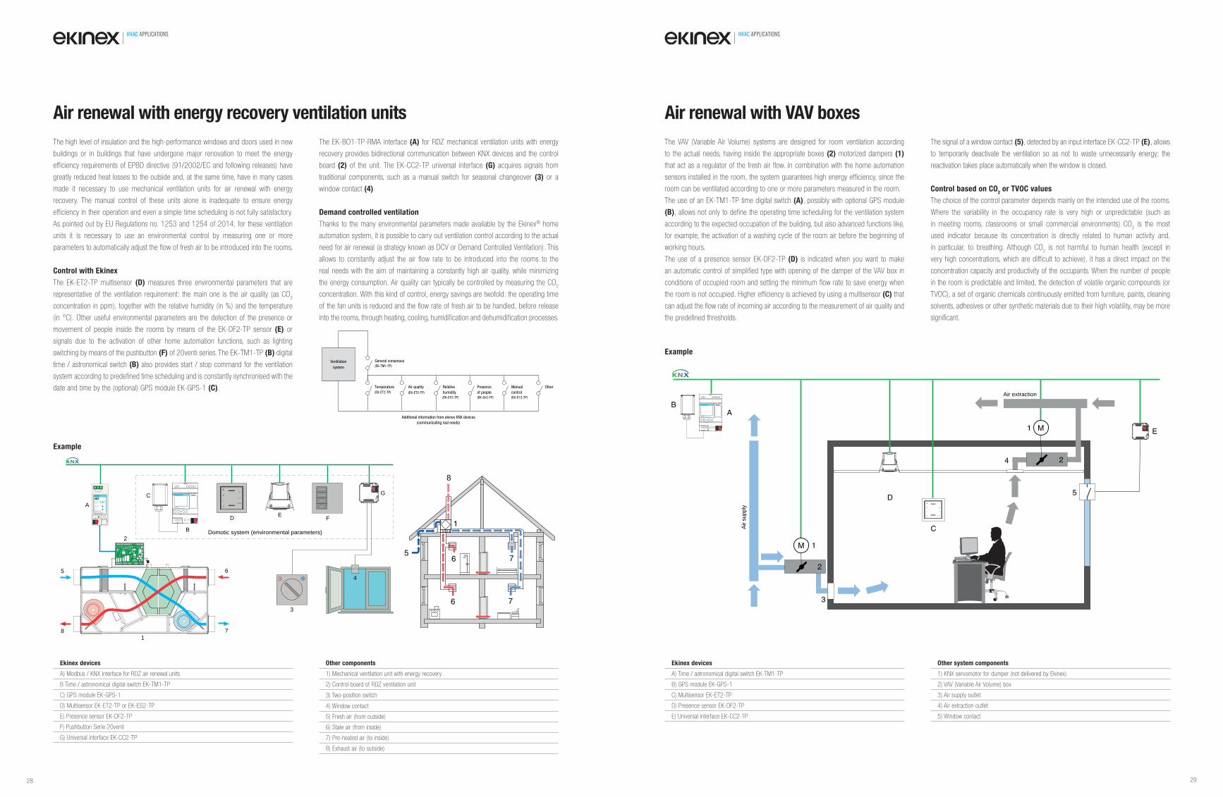
HVAC APPLICATIONS HVAC APPLICATIONS
The VAV (Variable Air Volume) systems are designed for room ventilation according
to the actual needs, having inside the appropriate boxes (2) motorized dampers (1)
that act as a regulator of the fresh air flow. In combination with the home automation
sensors installed in the room, the system guarantees high energy efficiency, since the
room can be ventilated according to one or more parameters measured in the room.
The use of an EK-TM1-TP time digital switch (A), possibly with optional GPS module
(B), allows not only to define the operating time scheduling for the ventilation system
according to the expected occupation of the building, but also advanced functions like,
for example, the activation of a washing cycle of the room air before the beginning of
working hours.
The use of a presence sensor EK-DF2-TP (D) is indicated when you want to make
an automatic control of simplified type with opening of the damper of the VAV box in
conditions of occupied room and setting the minimum flow rate to save energy when
the room is not occupied. Higher efficiency is achieved by using a multisensor (C) that
can adjust the flow rate of incoming air according to the measurement of air quality and
the predefined thresholds.
The signal of a window contact (5), detected by an input interface EK-CC2-TP (E), allows
to temporarily deactivate the ventilation so as not to waste unnecessarily energy; the
reactivation takes place automatically when the window is closed.
Control based on CO2 or TVOC values
The choice of the control parameter depends mainly on the intended use of the rooms.
Where the variability in the occupancy rate is very high or unpredictable (such as
in meeting rooms, classrooms or small commercial environments) CO2 is the most
used indicator because its concentration is directly related to human activity and,
in particular, to breathing. Although CO2 is not harmful to human health (except in
very high concentrations, which are difficult to achieve), it has a direct impact on the
concentration capacity and productivity of the occupants. When the number of people
in the room is predictable and limited, the detection of volatile organic compounds (or
TVOC), a set of organic chemicals continuously emitted from furniture, paints, cleaning
solvents, adhesives or other synthetic materials due to their high volatility, may be more
significant.
Air renewal with VAV boxes
Air extraction
Air s
uppl
y
M
M
1
1
2
2
3
4
5
EK-TM1-TPDigital time / Astronomical switch
AB
C
D
E
Example
Ekinex devices
A) Time / astronomical digital switch EK-TM1-TP
B) GPS module EK-GPS-1
C) Multisensor EK-ET2-TP
D) Presence sensor EK-DF2-TP
E) Universal interface EK-CC2-TP
Other system components
1) KNX servomotor for dumper (not delivered by Ekinex)
2) VAV (Variable Air Volume) box
3) Air supply outlet
4) Air extraction outlet
5) Window contact
The high level of insulation and the high-performance windows and doors used in new
buildings or in buildings that have undergone major renovation to meet the energy
efficiency requirements of EPBD directive (91/2002/EC and following releases) have
greatly reduced heat losses to the outside and, at the same time, have in many cases
made it necessary to use mechanical ventilation units for air renewal with energy
recovery. The manual control of these units alone is inadequate to ensure energy
efficiency in their operation and even a simple time scheduling is not fully satisfactory.
As pointed out by EU Regulations no. 1253 and 1254 of 2014, for these ventilation
units it is necessary to use an environmental control by measuring one or more
parameters to automatically adjust the flow of fresh air to be introduced into the rooms.
Control with Ekinex
The EK-ET2-TP multisensor (D) measures three environmental parameters that are
representative of the ventilation requirement: the main one is the air quality (as CO2
concentration in ppm), together with the relative humidity (in %) and the temperature
(in °C). Other useful environmental parameters are the detection of the presence or
movement of people inside the rooms by means of the EK-DF2-TP sensor (E) or
signals due to the activation of other home automation functions, such as lighting
switching by means of the pushbutton (F) of 20venti series. The EK-TM1-TP (B) digital
time / astronomical switch (B) also provides start / stop command for the ventilation
system according to predefined time scheduling and is constantly synchronised with the
date and time by the (optional) GPS module EK-GPS-1 (C).
The EK-BO1-TP-RMA interface (A) for RDZ mechanical ventilation units with energy
recovery provides bidirectional communication between KNX devices and the control
board (2) of the unit. The EK-CC2-TP universal interface (G) acquires signals from
traditional components, such as a manual switch for seasonal changeover (3) or a
window contact (4).
Demand controlled ventilation
Thanks to the many environmental parameters made available by the Ekinex® home
automation system, it is possible to carry out ventilation control according to the actual
need for air renewal (a strategy known as DCV or Demand Controlled Ventilation). This
allows to constantly adjust the air flow rate to be introduced into the rooms to the
real needs with the aim of maintaining a constantly high air quality, while minimizing
the energy consumption. Air quality can typically be controlled by measuring the CO2
concentration. With this kind of control, energy savings are twofold: the operating time
of the fan units is reduced and the flow rate of fresh air to be handled, before release
into the rooms, through heating, cooling, humidification and dehumidification processes.
Air renewal with energy recovery ventilation units
General consensus(EK-TM1-TP)
Temperature Air quality Relative
humidity
Presence
of people
Manual
control
Other
(EK-ET2-TP) (EK-ET2-TP)
(EK-ET2-TP) (EK-Dx2-TP) (EK-E12-TP)
Ventilation
system
Additional information from ekinex KNX devices
(communicating real needs)
Domotic system (environmental parameters)
EK-TM1-TPDigital time / Astronomical switch
B
CTVOC
CO2
traffic
R
Error
Modbus / KNX interface forRDZ air handling units
EK-BO1-TP-RMA
Modbus
Power
RXTX
greenred
A B
KNXProgr.
RS-485 Modbus
A
D E F
COMFORT
OFF
ECONOMY
BOOST
G
3
4
1
2
5 6
8 7
Example
6 7
6 75
1
8
Ekinex devices
A) Modbus / KNX interface for RDZ air renewal units
B Time / astronomical digital switch EK-TM1-TP
C) GPS module EK-GPS-1
D) Multisensor EK-ET2-TP or EK-ES2-TP
E) Presence sensor EK-DF2-TP
F) Pushbutton Serie 20venti
G) Universal interface EK-CC2-TP
Other components
1) Mechanical ventilation unit with energy recovery
2) Control board of RDZ ventilation unit
3) Two-position switch
4) Window contact
5) Fresh air (from outside)
6) Stale air (from inside)
7) Pre-heated air (to inside)
8) Exhaust air (to outside)
28 29
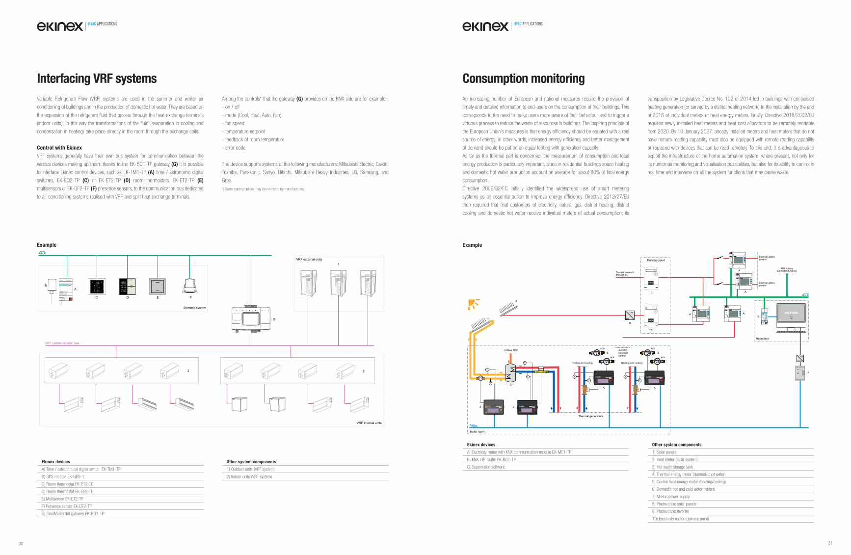
HVAC APPLICATIONS HVAC APPLICATIONS
Variable Refrigerant Flow (VRF) systems are used in the summer and winter air
conditioning of buildings and in the production of domestic hot water. They are based on
the expansion of the refrigerant fluid that passes through the heat exchange terminals
(indoor units); in this way the transformations of the fluid (evaporation in cooling and
condensation in heating) take place directly in the room through the exchange coils.
Control with Ekinex
VRF systems generally have their own bus system for communication between the
various devices making up them; thanks to the EK-BQ1-TP gateway (G) it is possible
to interface Ekinex control devices, such as EK-TM1-TP (A) time / astronomic digital
switches, EK-EQ2-TP (C) or EK-E72-TP (D) room thermostats, EK-ET2-TP (E)
multisensors or EK-DF2-TP (F) presence sensors, to the communication bus dedicated
to air conditioning systems realised with VRF and split heat exchange terminals.
Among the controls* that the gateway (G) provides on the KNX side are for example:
- on / off
- mode (Cool, Heat, Auto, Fan)
- fan speed
- temperature setpoint
- feedback of room temperature
- error code
The device supports systems of the following manufacturers: Mitsubishi Electric, Daikin,
Toshiba, Panasonic, Sanyo, Hitachi, Mitsubishi Heavy Industries, LG, Samsung, and
Gree.
*) Some control options may be restricted by manufacturers.
Interfacing VRF systems
Example
Ekinex devices
A) Time / astronomical digital switch EK-TM1-TP
B) GPS module EK-GPS-1
C) Room thermostat EK-E12-TP
D) Room thermostat EK-EP2-TP
E) Multisensor EK-ET2-TP
F) Presence sensor EK-DF2-TP
G) CoolMasterNet gateway EK-BQ1-TP
Other system components
1) Outdoor units (VRF system)
2) Indoor units (VRF system)
An increasing number of European and national measures require the provision of
timely and detailed information to end-users on the consumption of their buildings. This
corresponds to the need to make users more aware of their behaviour and to trigger a
virtuous process to reduce the waste of resources in buildings. The inspiring principle of
the European Union’s measures is that energy efficiency should be equated with a real
source of energy; in other words, increased energy efficiency and better management
of demand should be put on an equal footing with generation capacity.
As far as the thermal part is concerned, the measurement of consumption and local
energy production is particularly important, since in residential buildings space heating
and domestic hot water production account on average for about 80% of final energy
consumption.
Directive 2006/32/EC initially identified the widespread use of smart metering
systems as an essential action to improve energy efficiency. Directive 2012/27/EU
then required that final customers of electricity, natural gas, district heating, district
cooling and domestic hot water receive individual meters of actual consumption; its
transposition by Legislative Decree No. 102 of 2014 led in buildings with centralised
heating generation (or served by a district heating network) to the installation by the end
of 2016 of individual meters or heat energy meters. Finally, Directive 2018/2002/EU
requires newly installed heat meters and heat cost allocators to be remotely readable
from 2020. By 10 January 2027, already installed meters and heat meters that do not
have remote reading capability must also be equipped with remote reading capability
or replaced with devices that can be read remotely. To this end, it is advantageous to
exploit the infrastructure of the home automation system, where present, not only for
its numerous monitoring and visualisation possibilities, but also for its ability to control in
real time and intervene on all the system functions that may cause waste.
Consumption monitoring
Ekinex devices
A) Electricity meter with KNX communication module EK-MC1-TP
B) KNX / IP router EK-BC1-TP
C) Supervision software
Other system components
1) Solar panels
2) Heat meter (solar system)
3) Hot water storage tank
4) Thermal energy meter (domestic hot water)
5) Central heat energy meter (heating/cooling)
6) Domestic hot and cold water meters
7) M-Bus power supply
8) Photovoltaic solar panels
9) Photovoltaic inverter
10) Electricity meter (delivery point)
Example
2 4
1
Boiler room
EK-MC1-TP
POWER
STATUS
PROG
R
EK-ME1-06T
3
A
Reception
busstatus
traffic
GA
function
PA
R EK-BC1-TPIP router
IP TPB
RS485
COCONCONTECAEASY
T
T
RS485
EASYCONTECA
EASY
M07 125907185865T
T
T
T
1
59
6
RS485
USB
5
RS485
EASYCONTECA
EASYT
T
Utilities
5
RS485
EASYCONTECA
EASYT
T
AFS
ACS
AFS
ACS
A
7
8
=~
9
EK-MC1-TP
POWER
STATUS
PROG
R
EK-ME1-06T
EK-MC1-TP
POWER
STATUS
PROG
R
EK-ME1-06T
EK-MC1-TP
POWER
STATUS
PROG
R
EK-ME1-06T
A
A
10
6 6
C
10
Heating and cooling Heating and cooling
30 31
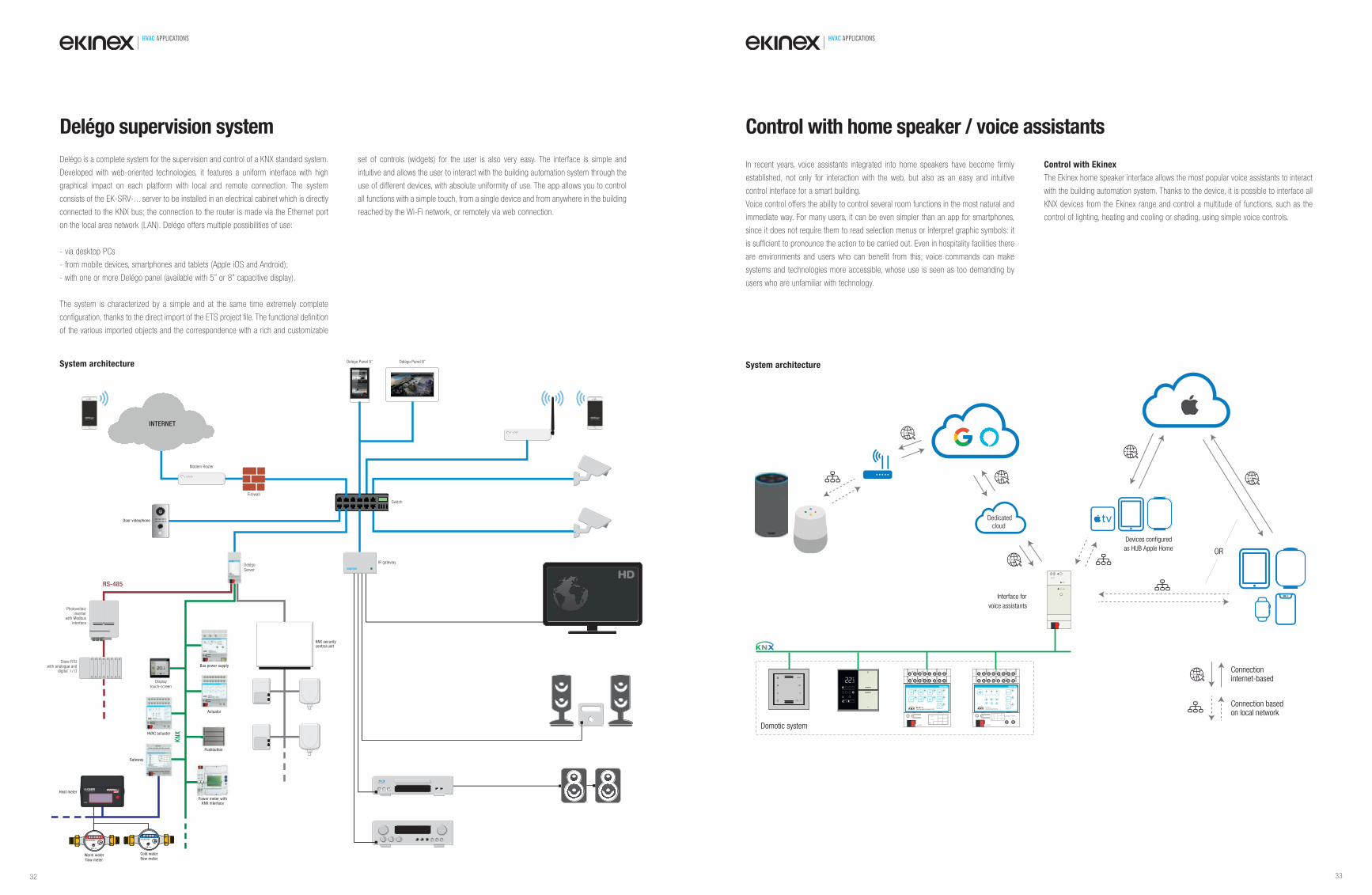
HVAC APPLICATIONS HVAC APPLICATIONS
Control with home speaker / voice assistants
In recent years, voice assistants integrated into home speakers have become firmly
established, not only for interaction with the web, but also as an easy and intuitive
control interface for a smart building.
Voice control offers the ability to control several room functions in the most natural and
immediate way. For many users, it can be even simpler than an app for smartphones,
since it does not require them to read selection menus or interpret graphic symbols: it
is sufficient to pronounce the action to be carried out. Even in hospitality facilities there
are environments and users who can benefit from this; voice commands can make
systems and technologies more accessible, whose use is seen as too demanding by
users who are unfamiliar with technology.
Control with Ekinex
The Ekinex home speaker interface allows the most popular voice assistants to interact
with the building automation system. Thanks to the device, it is possible to interface all
KNX devices from the Ekinex range and control a multitude of functions, such as the
control of lighting, heating and cooling or shading, using simple voice controls.
Dev.
Line
Area
bus KNX
1A
3 4 5 6 7 81 2
1B 2A 2B
3A
11 219 01
3B 4A 4B
L N
51 6131 41
L N
N
N
RESET
12-24 DC
- +
STATUS LED
IN14 3
C11 21
V1 V231 41
V351 61
DO171 81
DO2
IN26 5
IN38 7
0-10V9 01
1 2
L NDev.
Line
Area
bus KNX
-+
230Vac-50/60Hz
3 1DO1
2
DO2
EK-HC1-TPFan-coil actuator/controller
Dedicatedcloud
Devices configured
as HUB Apple Home OR
Connection internet-based
Connection basedon local network
Interface for
voice assistants
Domotic system
System architecture
Delégo is a complete system for the supervision and control of a KNX standard system.
Developed with web-oriented technologies, it features a uniform interface with high
graphical impact on each platform with local and remote connection. The system
consists of the EK-SRV-... server to be installed in an electrical cabinet which is directly
connected to the KNX bus; the connection to the router is made via the Ethernet port
on the local area network (LAN). Delégo offers multiple possibilities of use:
- via desktop PCs
- from mobile devices, smartphones and tablets (Apple iOS and Android);
- with one or more Delégo panel (available with 5” or 8” capacitive display).
The system is characterized by a simple and at the same time extremely complete
configuration, thanks to the direct import of the ETS project file. The functional definition
of the various imported objects and the correspondence with a rich and customizable
set of controls (widgets) for the user is also very easy. The interface is simple and
intuitive and allows the user to interact with the building automation system through the
use of different devices, with absolute uniformity of use. The app allows you to control
all functions with a simple touch, from a single device and from anywhere in the building
reached by the Wi-Fi network, or remotely via web connection.
Delégo supervision system
System architecture
KN
X
Bus power supply
Actuator
PushbuttonP hb
Display touch-screen
HVAC actuator
Gateway
Power meter with KNX interface
Power meter wower meter w
Heat meter
Warm water flow meter
DelégoServer
KNX security central unit
IR gateway
Cold waterflow meter
Door videophone
INTERNET
Firewall
Switch
Modem Router
Delégo Panel 5” Delégo Panel 8”
Slave RTUwith analogue and
digital I / O
Photovoltaic inverter
with Modbus interface
RS-485
RS485
EASYEEAEASEASYCO
EASYC
EASYCON
EASYCONTECA
EASYCONT
EASYCONTE
EASYCONTEC
EASYCONTECA
EASY
32 33
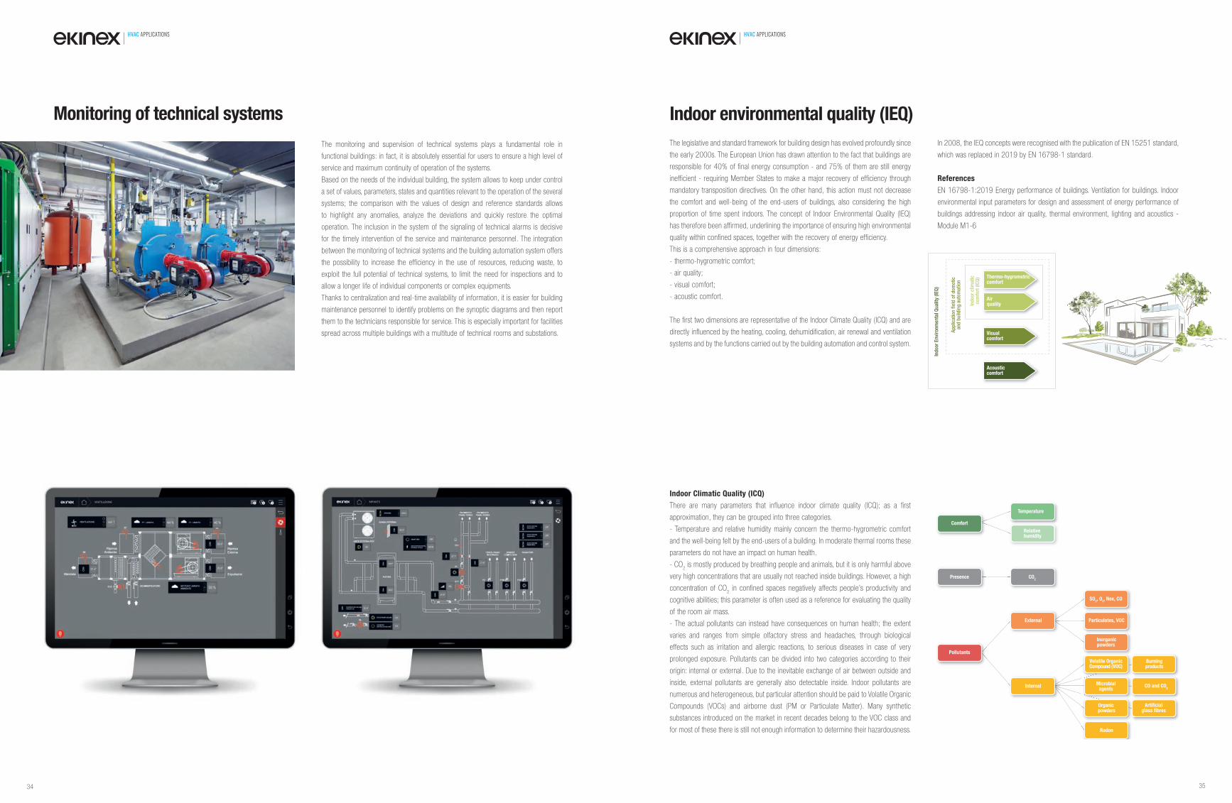
HVAC APPLICATIONS HVAC APPLICATIONS
The legislative and standard framework for building design has evolved profoundly since
the early 2000s. The European Union has drawn attention to the fact that buildings are
responsible for 40% of final energy consumption - and 75% of them are still energy
inefficient - requiring Member States to make a major recovery of efficiency through
mandatory transposition directives. On the other hand, this action must not decrease
the comfort and well-being of the end-users of buildings, also considering the high
proportion of time spent indoors. The concept of Indoor Environmental Quality (IEQ)
has therefore been affirmed, underlining the importance of ensuring high environmental
quality within confined spaces, together with the recovery of energy efficiency.
This is a comprehensive approach in four dimensions:
- thermo-hygrometric comfort;
- air quality;
- visual comfort;
- acoustic comfort.
The first two dimensions are representative of the Indoor Climate Quality (ICQ) and are
directly influenced by the heating, cooling, dehumidification, air renewal and ventilation
systems and by the functions carried out by the building automation and control system.
In 2008, the IEQ concepts were recognised with the publication of EN 15251 standard,
which was replaced in 2019 by EN 16798-1 standard.
References
EN 16798-1:2019 Energy performance of buildings. Ventilation for buildings. Indoor
environmental input parameters for design and assessment of energy performance of
buildings addressing indoor air quality, thermal environment, lighting and acoustics -
Module M1-6
Indoor environmental quality (IEQ)
Indoor Climatic Quality (ICQ)
There are many parameters that influence indoor climate quality (ICQ); as a first
approximation, they can be grouped into three categories.
- Temperature and relative humidity mainly concern the thermo-hygrometric comfort
and the well-being felt by the end-users of a building. In moderate thermal rooms these
parameters do not have an impact on human health.
- CO2 is mostly produced by breathing people and animals, but it is only harmful above
very high concentrations that are usually not reached inside buildings. However, a high
concentration of CO2 in confined spaces negatively affects people’s productivity and
cognitive abilities; this parameter is often used as a reference for evaluating the quality
of the room air mass.
- The actual pollutants can instead have consequences on human health; the extent
varies and ranges from simple olfactory stress and headaches, through biological
effects such as irritation and allergic reactions, to serious diseases in case of very
prolonged exposure. Pollutants can be divided into two categories according to their
origin: internal or external. Due to the inevitable exchange of air between outside and
inside, external pollutants are generally also detectable inside. Indoor pollutants are
numerous and heterogeneous, but particular attention should be paid to Volatile Organic
Compounds (VOCs) and airborne dust (PM or Particulate Matter). Many synthetic
substances introduced on the market in recent decades belong to the VOC class and
for most of these there is still not enough information to determine their hazardousness.
Comfort
Temperature
Relativehumidity
Presence CO2
Pollutants
External
Internal
SO2, O
3, Nox, CO
Inorganicpowders
Particulates, VOC
Burningproducts
CO and CO2
Artificial glass fibres
Volatile OrganicCompound (VOC)
Organic powders
Microbial agents
Radon
Thermo-hygrometriccomfort
Ind
oor
clim
atic
com
fort
(IC
Q)
Ap
plic
atio
n fi
eld
of
dom
otic
and
bu
ildin
g a
uto
mat
ion
Ind
oor
En
viro
nm
enta
l Qu
alit
y (I
EQ
)
Airquality
Visualcomfort
Acousticcomfort
The monitoring and supervision of technical systems plays a fundamental role in
functional buildings: in fact, it is absolutely essential for users to ensure a high level of
service and maximum continuity of operation of the systems.
Based on the needs of the individual building, the system allows to keep under control
a set of values, parameters, states and quantities relevant to the operation of the several
systems; the comparison with the values of design and reference standards allows
to highlight any anomalies, analyze the deviations and quickly restore the optimal
operation. The inclusion in the system of the signaling of technical alarms is decisive
for the timely intervention of the service and maintenance personnel. The integration
between the monitoring of technical systems and the building automation system offers
the possibility to increase the efficiency in the use of resources, reducing waste, to
exploit the full potential of technical systems, to limit the need for inspections and to
allow a longer life of individual components or complex equipments.
Thanks to centralization and real-time availability of information, it is easier for building
maintenance personnel to identify problems on the synoptic diagrams and then report
them to the technicians responsible for service. This is especially important for facilities
spread across multiple buildings with a multitude of technical rooms and substations.
Monitoring of technical systems
34 35
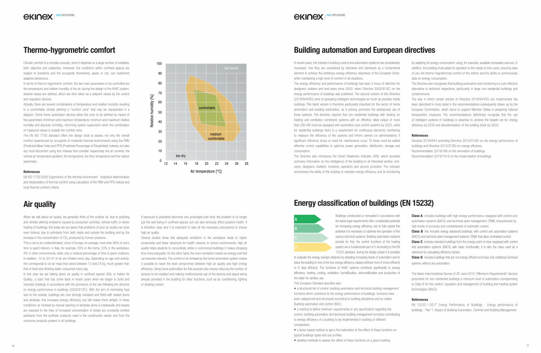
HVAC APPLICATIONS HVAC APPLICATIONS
Climatic comfort is a complex concept, since it depends on a large number of variables,
both objective and subjective; moreover, the conditions within confined spaces are
subject to transients and the occupants themselves, aware or not, can implement
adaptive behaviours.
In terms of thermo-hygrometric comfort, the two main parameters to be controlled are
the temperature and relative humidity of the air; during the design of the HVAC system,
desired values are defined, which are then taken as a setpoint values by the control
and regulation devices.
Actually, there are several combinations of temperature and relative humidity resulting
in a comfortable climate defining a “comfort zone” that may be represented in a
diagram. Some home automation devices allow this zone to be defined by means of
five parameters (minimum and maximum temperature, minimum and maximum relative
humidity and absolute humidity), informing system supervision when the combination
of measured values is outside the comfort zone.
The EN ISO 7730 standard offers the design tools to assess not only the overall
comfort experienced by occupants of moderate thermal environments using the PMV
(Predicted Mean Vote) and PPD (Predicted Percentage of Dissatisfied) indexes, but also
any local discomfort using four indexes that consider respectively the air currents, the
vertical air temperature gradient, the temperature, the floor temperature and the radiant
asymmetry.
References
EN ISO 7730:2005 Ergonomics of the thermal environment - Analytical determination
and interpretation of thermal comfort using calculation of the PMV and PPD indices and
local thermal comfort criteria
Thermo-hygrometric comfort
When we talk about air quality, we generally think of the outdoor air, due to polluting
and climate-altering emissions caused by production activities, vehicle traffic or winter
heating of buildings. But today we are aware that problems of poor air quality can arise
even indoors, due to pollutants from both inside and outside the building and by the
increase in the concentration of CO2 produced by human presence.
This is not to be underestimated, since in Europe, on average, more than 90% of one’s
time is spent indoors: in Italy, for example, 55% in the home, 33% in the workplace,
4% in other environments, while only a residual percentage of time is spent outdoors.
In addition, 10 to 20 m³ of air are inhaled every day, depending on age and activity:
this corresponds to an air mass that varies between 12 and 24 kg, much greater than
that of food and drinking water consumed every day.
In this case we are talking about air quality in confined spaces (IAQ, or Indoor Air
Quality), a topic that has come back in recent years when we began to build and
renovate buildings in accordance with the provisions of the law following the directive
on energy performance in buildings (2002/91/EC). With the aim of minimising heat
loss to the outside, buildings are now strongly insulated and fitted with sealed doors
and windows; this increases energy efficiency, but still makes them airtight. In these
conditions, air renewal by manual opening of windows alone is inadequate and people
are exposed to the risks of increased concentration of slowly but constantly emitted
pollutants from the synthetic products used in the construction sector and from the
consumer products present in all buildings.
If exposure to pollutants becomes very prolonged over time, the problem is no longer
just the well-being in confined spaces, but can also seriously affect people’s health. It
is therefore clear why it is important to take all the necessary precautions to ensure
high air quality.
Several studies show that adequate ventilation in the workplace leads to higher
productivity and fewer absences for health reasons. In school environments, high air
quality helps students to concentrate, while in commercial buildings it makes shopping
time more enjoyable. On the other hand, the room ventilation means an energy cost that
can become relevant. The control of air renewal by the home automation system makes
it possible to reach the best compromise between high air quality and high energy
efficiency. Using home automation for this purpose also means reducing the number of
sensors to be installed and making multifunctional use of the devices and signal wiring
already provided in the building for other functions, such as air conditioning, lighting
or shading control.
Air quality
Air temperature [°C]
Rel
ativ
e hu
mid
ity [
%]
comfortable
too humid
too dry
medium
comfortable
12 14 16 18 20 22 24 26 280
10
20
30
40
50
60
70
80
90
100
Buildings constructed or renovated in accordance with
the latest legal requirements offer considerable potential
for increasing energy effi ciency, but to fully exploit this
potential it is necessary to optimise the operation of the
various technical systems. Building automation systems
provide for this; the control functions of the heating
system are a fundamental part of it. According to the EN
15232 standard, during the design phase it is possible
to evaluate the energy savings obtained by adopting increasing levels of automation and to
place the building in one of the four energy effi ciency classes defi ned: from A (more effi cient)
to D (less effi cient). The functions of HVAC systems contribute signifi cantly to energy
effi ciency: heating, cooling, ventilation, humidifi cation, dehumidifi cation and production of
hot water for sanitary use.
This European Standard specifies also:
• a structured list of control, building automation and technical building management
functions which contribute to the energy performance of buildings; functions have
been categorized and structured according to building disciplines and so called
Building automation and control (BAC);
• a method to define minimum requirements or any specification regarding the
control, building automation and technical building management functions contributing
to energy efficiency of a building to be implemented in building of different
complexities;
• a factor based method to get a first estimation of the effect of these functions on
typical buildings types and use profiles;
• detailed methods to assess the effect of these functions on a given building.
Class A: includes buildings with high energy performance, equipped with control and
automation systems (BACS) and technical plant management (TBM) characterized by
high levels of accuracy and completeness of automatic control.
Class B: this includes energy advanced buildings, with control and automation systems
(BACS) and technical plant management systems (TBM) that allow centralised control.
Class C: includes standard buildings from the energy point of view, equipped with control
and automation systems (BACS) with basic functionality. It is also the class used as a
reference for calculating effi ciency factors.
Class D: includes buildings that are not energy effi cient and have only traditional technical
systems, without any automation.
The Italian Interministerial Decree of 26 June 2015 (“Minimum Requirements” decree)
prescribes for non-residential buildings a minimum level of automation corresponding
to Class B for the control, regulation and management of building and heating system
technologies (BACS).
References
EN 15232-1:2017 Energy Performance of Buildings - Energy performance of
buildings - Part 1: Impact of Building Automation, Controls and Building Management
Energy classifi cation of buildings (EN 15232)
In recent years, the interest in building control and automation systems has considerably
increased: now they are considered by directives and standards as a fundamental
element to achieve the ambitious energy efficiency objectives of the European Union,
while maintaining a high level of comfort in all situations.
The energy efficiency and performance of buildings has been a focus of attention for
designers, builders and end-users since 2002, when Directive 2002/91/EC on the
energy performance of buildings was published. The second revision of this Directive
(2018/844/EU) aims at spreading intelligent technologies as much as possible inside
buildings. This latest version is therefore particularly important for the sector of home
automation and building automation, as it actively promotes the widespread use of
these systems. The directive requires that non-residential buildings with heating (or
heating and ventilation combined) systems with an effective rated output of more
than 290 kW must be equipped with automation and control systems by 2025, while
for residential buildings there is a requirement for continuous electronic monitoring
to measure the efficiency of the systems and inform owners (or administrators) if
significant efficiency drops or need for maintenance occur. To these must be added
effective control capabilities to optimize power generation, distribution, storage and
consumption.
The Directive also introduces the Smart Readiness Indicator (SRI), which provides
summary information on the intelligence of the building to all interested parties: end-
users, designers, builders, investors, operators and service providers. The indicator
summarises the ability of the building to maintain energy efficiency and its functioning
by adapting its energy consumption using, for example, available renewable sources. In
addition, the building must adapt its operation to the needs of end-users, ensuring ease
of use, the thermo-hygrothermal comfort of the interior and the ability to communicate
data on energy consumption.
The Directive also recognises that building automation and monitoring is a cost-effective
alternative to technical inspections, particularly in large non-residential buildings and
condominiums.
The way in which certain articles of Directive 2018/844/EU are implemented has
been described in more detail in the recommendations subsequently drawn up by the
European Commission, which serve to support Member States in preparing national
transposition measures. The recommendations definitively recognise that the use
of intelligent systems in buildings is essential to achieve the targets set for energy
efficiency by 2030 and decarbonisation of the building stock by 2050.
References
Directive 2018/844 amending Directive 2010/31/EU on the energy performance of
buildings and Directive 2012/27/EU on energy efficiency
Recommendation 2019/786 on the renovation of buildings
Recommendation 2019/1019 on the modernisation of buildings
Building automation and European directives
A
B
C
D
36 37
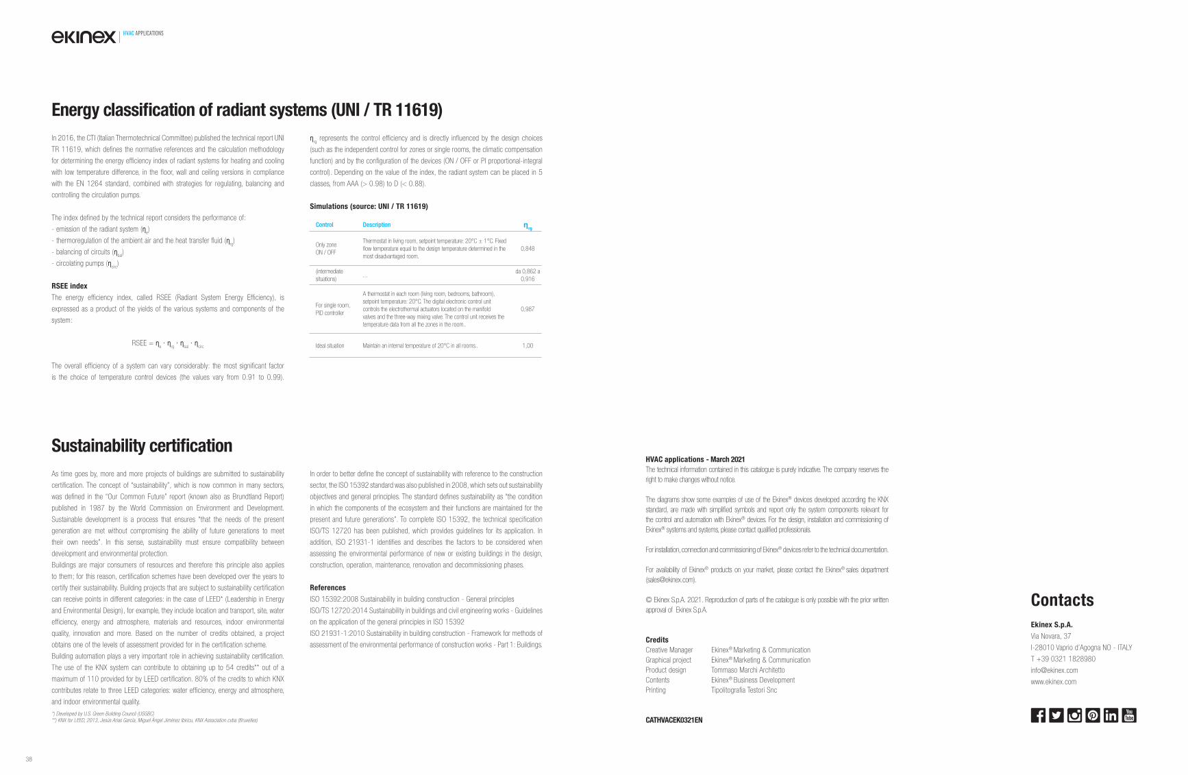
HVAC APPLICATIONS
In 2016, the CTI (Italian Thermotechnical Committee) published the technical report UNI
TR 11619, which defines the normative references and the calculation methodology
for determining the energy efficiency index of radiant systems for heating and cooling
with low temperature difference, in the floor, wall and ceiling versions in compliance
with the EN 1264 standard, combined with strategies for regulating, balancing and
controlling the circulation pumps.
The index defined by the technical report considers the performance of:
- emission of the radiant system (ηe)
- thermoregulation of the ambient air and the heat transfer fluid (ηrg)
- balancing of circuits (ηbal
)
- circolating pumps (ηcirc
)
RSEE index
The energy efficiency index, called RSEE (Radiant System Energy Efficiency), is
expressed as a product of the yields of the various systems and components of the
system:
RSEE = ηe ∙ η
rg ∙ η
bal ∙ η
circ
The overall efficiency of a system can vary considerably: the most significant factor
is the choice of temperature control devices (the values vary from 0.91 to 0.99).
ηrg represents the control efficiency and is directly influenced by the design choices
(such as the independent control for zones or single rooms, the climatic compensation
function) and by the configuration of the devices (ON / OFF or PI proportional-integral
control). Depending on the value of the index, the radiant system can be placed in 5
classes, from AAA (> 0.98) to D (< 0.88).
Simulations (source: UNI / TR 11619)
As time goes by, more and more projects of buildings are submitted to sustainability
certification. The concept of “sustainability”, which is now common in many sectors,
was defined in the “Our Common Future” report (known also as Brundtland Report)
published in 1987 by the World Commission on Environment and Development.
Sustainable development is a process that ensures “that the needs of the present
generation are met without compromising the ability of future generations to meet
their own needs”. In this sense, sustainability must ensure compatibility between
development and environmental protection.
Buildings are major consumers of resources and therefore this principle also applies
to them; for this reason, certification schemes have been developed over the years to
certify their sustainability. Building projects that are subject to sustainability certification
can receive points in different categories: in the case of LEED* (Leadership in Energy
and Environmental Design), for example, they include location and transport, site, water
efficiency, energy and atmosphere, materials and resources, indoor environmental
quality, innovation and more. Based on the number of credits obtained, a project
obtains one of the levels of assessment provided for in the certification scheme.
Building automation plays a very important role in achieving sustainability certification.
The use of the KNX system can contribute to obtaining up to 54 credits** out of a
maximum of 110 provided for by LEED certification. 80% of the credits to which KNX
contributes relate to three LEED categories: water efficiency, energy and atmosphere,
and indoor environmental quality.
*) Developed by U.S. Green Building Council (USGBC)
**) KNX for LEED, 2013, Jesús Arias García, Miguel Ángel Jiménez Ibiricu, KNX Association cvba (Bruxelles)
In order to better define the concept of sustainability with reference to the construction
sector, the ISO 15392 standard was also published in 2008, which sets out sustainability
objectives and general principles. The standard defines sustainability as “the condition
in which the components of the ecosystem and their functions are maintained for the
present and future generations”. To complete ISO 15392, the technical specification
ISO/TS 12720 has been published, which provides guidelines for its application. In
addition, ISO 21931-1 identifies and describes the factors to be considered when
assessing the environmental performance of new or existing buildings in the design,
construction, operation, maintenance, renovation and decommissioning phases.
References
ISO 15392:2008 Sustainability in building construction - General principles
ISO/TS 12720:2014 Sustainability in buildings and civil engineering works - Guidelines
on the application of the general principles in ISO 15392
ISO 21931-1:2010 Sustainability in building construction - Framework for methods of
assessment of the environmental performance of construction works - Part 1: Buildings.
Sustainability certifi cation
Energy classifi cation of radiant systems (UNI / TR 11619)
Control Description ηrg
Only zone
ON / OFF
Thermostat in living room, setpoint temperature: 20°C ± 1°C. Fixed
fl ow temperature equal to the design temperature determined in the
most disadvantaged room.
0,848
(intermediate
situations)...
da 0,862 a
0,916
For single room,
PID controller
A thermostat in each room (living room, bedrooms, bathroom),
setpoint temperature: 20°C. The digital electronic control unit
controls the electrothermal actuators located on the manifold
valves and the three-way mixing valve. The control unit receives the
temperature data from all the zones in the room..
0,987
Ideal situation Maintain an internal temperature of 20°C in all rooms.. 1,00
HVAC applications - March 2021
The technical information contained in this catalogue is purely indicative. The company reserves the
right to make changes without notice.
The diagrams show some examples of use of the Ekinex® devices developed according the KNX
standard, are made with simplifi ed symbols and report only the system components relevant for
the control and automation with Ekinex® devices. For the design, installation and commissioning of
Ekinex® systems and systems, please contact qualifi ed professionals.
For installation, connection and commissioning of Ekinex® devices refer to the technical documentation.
For availability of Ekinex® products on your market, please contact the Ekinex® sales department
© Ekinex S.p.A. 2021. Reproduction of parts of the catalogue is only possible with the prior written
approval of Ekinex S.p.A.
Credits
Creative Manager Ekinex® Marketing & Communication
Graphical project Ekinex® Marketing & Communication
Product design Tommaso Marchi Architetto
Contents Ekinex® Business Development
Printing Tipolitografia Testori Snc
CATHVACEK0321EN
Contacts
Ekinex S.p.A.
Via Novara, 37
I-28010 Vaprio d’Agogna NO - ITALY
T +39 0321 1828980
www.ekinex.com
38

www.ekinex.com

![[O] cOmpaniessavarinocompanies.com/content/documents/bids... · hvac general notes hvac abbreviations hvac ductwork symbols hvac control symbols chaintreuil jensen stark architectural](https://img.pdfslide.us/doc/110x75/5ae5a13f7f8b9a29048c7dfa/o-compan-general-notes-hvac-abbreviations-hvac-ductwork-symbols-hvac-control-symbols.jpg)