Embed Size (px)
Citation preview
Prospects of integrating CAD and CAE in Simulation Data Management
Clemens Knehler(2), Marko Thiele(1),
David Matthus(1), Peter Friedrich(1)
(1) SCALE GmbH(2) AUDI AG
Presented at the NAFEMS European Conference
Simulation Process and Data Management (SPDM)
28-29 November 2018, Munich, Germany
Agenda
■ Integrating CAD and CAE
■ Body18 “Proof of Concept” at AUDI*
■ Proposed Approach
■ Data structure
■ Handling of connection information
■ Implementation of Body18 “Proof of Concept”
■ Integration of CATIA for CAD and ANSA for CAE
■ Closing the gap between CAD and CAE
■ Crafting simulations for different solvers and disciplines on the same data
■ Project management
■ Roundup
■ Outlook
* Disclaimer: This has not been deployed to a productive
environment! The intend was to investigate workflows.
Agenda
■ Integrating CAD and CAE
■ Body18 “Proof of Concept” at AUDI
■ Proposed Approach
■ Data structure
■ Handling of connection information
■ Implementation of Body18 “Proof of Concept”
■ Integration of CATIA for CAD and ANSA for CAE
■ Closing the gap between CAD and CAE
■ Crafting simulations for different solvers and disciplines on the same data
■ Project management
■ Roundup
■ Outlook
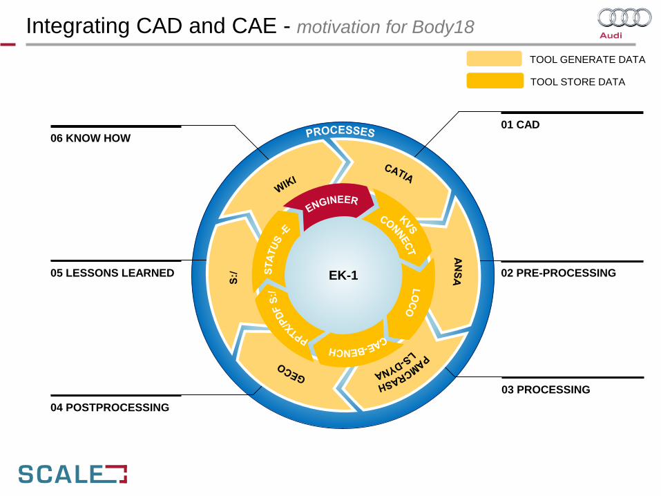
Integrating CAD and CAE - motivation for Body18
06 KNOW HOW
05 LESSONS LEARNED
04 POSTPROCESSING
01 CAD
02 PRE-PROCESSING
03 PROCESSING
EK-1
TOOL GENERATE DATA
TOOL STORE DATA
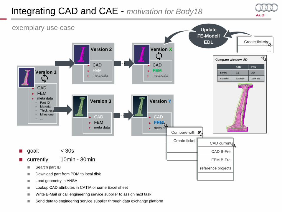
Integrating CAD and CAE - motivation for Body18
Compare window 3D
Version 1
► CAD
► FEM► meta data
• Part ID
• Material
• Thickness
• Milestone
• …
Version 2
► CAD
► FEM► meta data
Version X
► CAD
► FEM► meta data
Version 3
► CAD
► FEM► meta data
Version Y
► CAD
► FEM► meta data
Compare with …
Create ticket …
…
CAD current
CAD B-Frei
FEM B-Frei
reference projects
CAD FEM
t [mm] 2,1 2,2
material 22MnB5 22MnB5
Create ticket …
…
…
…
Update
FE-Modell
EDL
■ goal: < 30s
■ currently: 10min - 30min
■ Search part ID
■ Download part from PDM to local disk
■ Load geometry in ANSA
■ Lookup CAD attributes in CATIA or some Excel sheet
■ Write E-Mail or call engineering service supplier to assign next task
■ Send data to engineering service supplier through data exchange platform
► FEM
exemplary use case

Agenda
■ Integrating CAD and CAE
■ Body18 “Proof of Concept” at AUDI*
■ Proposed Approach
■ Data structure
■ Handling of connection information
■ Implementation of Body18 “Proof of Concept”
■ Integration of CATIA for CAD and ANSA for CAE
■ Closing the gap between CAD and CAE
■ Crafting simulations for different solvers and disciplines on the same data
■ Project management
■ Roundup
■ Outlook
* Disclaimer: This has not been deployed to a productive
environment! The intend was to investigate workflows.
Designer
(external)
Designer
Designer
Designer Planning
Simulation
Testing
Simulation
(external)
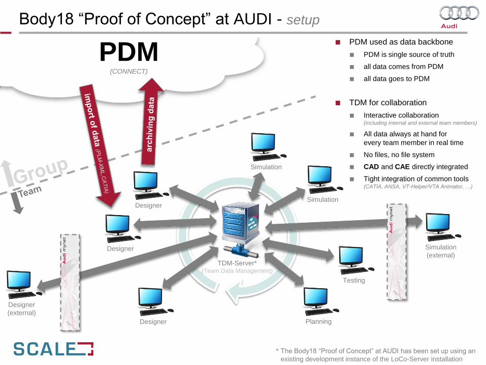
* The Body18 “Proof of Concept” at AUDI has been set up using an
existing development instance of the LoCo-Server installation
PDM(CONNECT)
TDM-Server*(Team Data Management)
■ PDM used as data backbone
■ PDM is single source of truth
■ all data comes from PDM
■ all data goes to PDM
■ TDM for collaboration
■ Interactive collaboration(including internal and external team members)
■ All data always at hand for
every team member in real time
■ No files, no file system
■ CAD and CAE directly integrated
■ Tight integration of common tools(CATIA, ANSA, VT-Helper/VTA Animator, …)
Simulation
Body18 “Proof of Concept” at AUDI - setup
Agenda
■ Integrating CAD and CAE
■ Body18 “Proof of Concept” at AUDI
■ Proposed Approach
■ Data structure
■ Handling of connection information
■ Implementation of Body18 “Proof of Concept”
■ Integration of CATIA for CAD and ANSA for CAE
■ Closing the gap between CAD and CAE
■ Crafting simulations for different solvers and disciplines on the same data
■ Project management
■ Roundup
■ Outlook
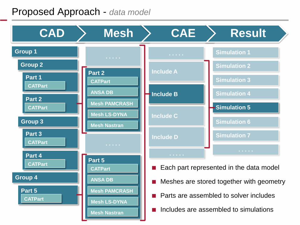
Proposed Approach - data model
CAD Mesh CAE Result
Group 2
Group 3
Group 1
Group 4
Part 5
Part 1
CATPart
Part 2
CATPart
Part 3
CATPart
Part 4
CATPart
CATPart
Part 2
CATPart
ANSA DB
Mesh PAMCRASH
Mesh LS-DYNA
Mesh Nastran
. . . . .
Part 5
CATPart
ANSA DB
Mesh PAMCRASH
Mesh LS-DYNA
Mesh Nastran
. . . . .
Include A
. . . . .
Include B
Include C
Include D
. . . . .
Simulation 1
Simulation 2
Simulation 3
Simulation 4
Simulation 5
Simulation 6
Simulation 7
. . . . .
■ Each part represented in the data model
■ Meshes are stored together with geometry
■ Parts are assembled to solver includes
■ Includes are assembled to simulations
■ Schweißpunkte, Schweißpunkte, …
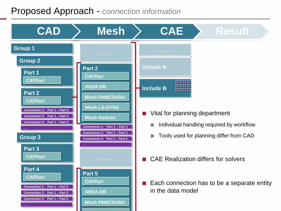
Proposed Approach - connection information
CAD Mesh CAE Result
Group 2
Group 3
Group 1
Part 1
CATPart
Part 2
CATPart
Part 3
CATPart
Part 4
CATPart
Part 2
CATPart
ANSA DB
Mesh PAMCRASH
Mesh LS-DYNA
Mesh Nastran
. . . . .
Part 5
CATPart
ANSA DB
Mesh PAMCRASH
Mesh LS-DYNA
. . . . .
Include A
. . . . .
Include B
Include C
Include D
. . . . .
Simulation 1
Simulation 2
Simulation 3
Simulation 4
Simulation 5
Simulation 6
Simulation 7
. . . . .
Connection 1: Part 1 – Part 2
Connection 2: Part 1 – Part 2
Connection 3: Part 1 – Part 2
…
Connection 1: Part 1 – Part 2
Connection 2: Part 1 – Part 2
Connection 3: Part 1 – Part 2
…
Connection 1: Part 1 – Part 2
Connection 2: Part 1 – Part 2
Connection 3: Part 1 – Part 2
…
■ Vital for planning department
■ Individual handling required by workflow
■ Tools used for planning differ from CAD
■ CAE Realization differs for solvers
■ Each connection has to be a separate entity
in the data model
Agenda
■ Integrating CAD and CAE
■ Body18 “Proof of Concept” at AUDI
■ Proposed Approach
■ Data structure
■ Handling of connection information
■ Implementation of Body18 “Proof of Concept”
■ Integration of CATIA for CAD and ANSA for CAE
■ Closing the gap between CAD and CAE
■ Crafting simulations for different solvers and disciplines on the same data
■ Project management
■ Roundup
■ Outlook
■ Schweißpunkte, Schweißpunkte, …CAD Mesh CAE Result
Group 2
Group 3
Group 1
Part 1
CATPart
Part 2
CATPart
Part 3
CATPart
Part 4
CATPart
Part 2
CATPart
ANSA DB
Mesh PAMCRASH
Mesh LS-DYNA
Mesh Nastran
. . . . .
Part 5
CATPart
ANSA DB
Mesh PAMCRASH
Mesh LS-DYNA
. . . . .
Include A
. . . . .
Include B
Include C
Include D
. . . . .
Simulation 1
Simulation 2
Simulation 3
Simulation 4
Simulation 5
Simulation 6
Simulation 7
. . . . .
Connection 1: Part 1 – Part 2
Connection 2: Part 1 – Part 2
Connection 3: Part 1 – Part 2
…
Connection 1: Part 1 – Part 2
Connection 2: Part 1 – Part 2
Connection 3: Part 1 – Part 2
…
Connection 1: Part 1 – Part 2
Connection 2: Part 1 – Part 2
Connection 3: Part 1 – Part 2
…
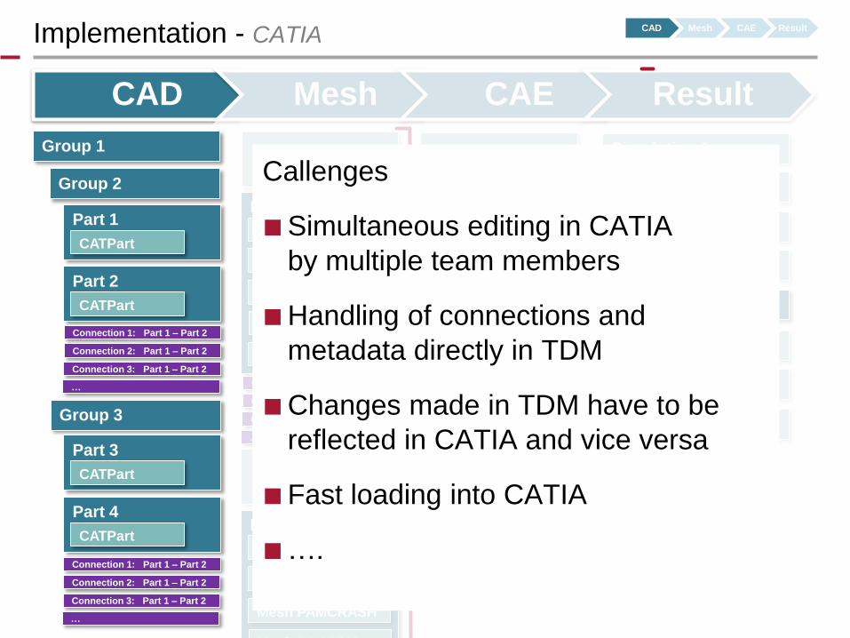
Implementation - CATIA
Callenges
■ Simultaneous editing in CATIA
by multiple team members
■ Handling of connections and
metadata directly in TDM
■ Changes made in TDM have to be
reflected in CATIA and vice versa
■ Fast loading into CATIA
■ ….
CAD Mesh CAE Result
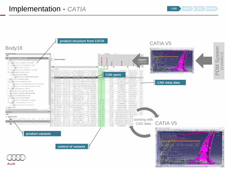
Implementation - CATIA
PD
M S
yste
m
(CO
NN
EC
T)
Import CATIA V5
product structure from CATIA
CAD parts
CAD meta data
product variants
working withCAD data
CATIA V5
CATIA V5
Body18
control of variants
CAD Mesh CAE Result
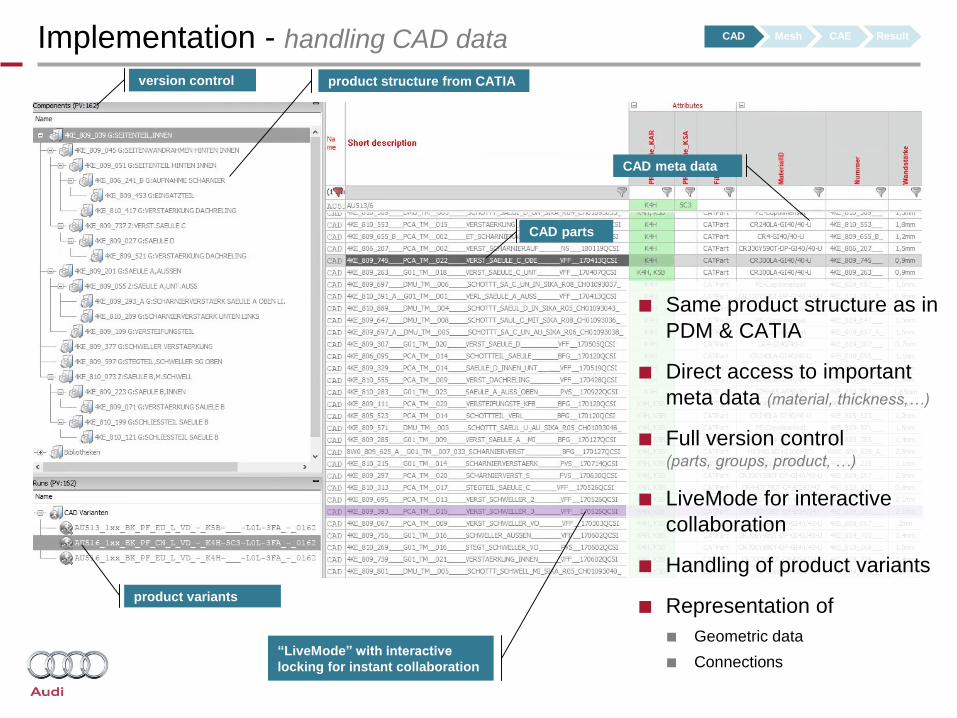
Implementation - handling CAD data
product structure from CATIA
CAD parts
CAD meta data
product variants
version control
■ Same product structure as in
PDM & CATIA
■ Direct access to important
meta data (material, thickness,…)
■ Full version control(parts, groups, product, …)
■ LiveMode for interactive
collaboration
■ Handling of product variants
■ Representation of
■ Geometric data
■ Connections“LiveMode” with interactive
locking for instant collaboration
CAD Mesh CAE Result
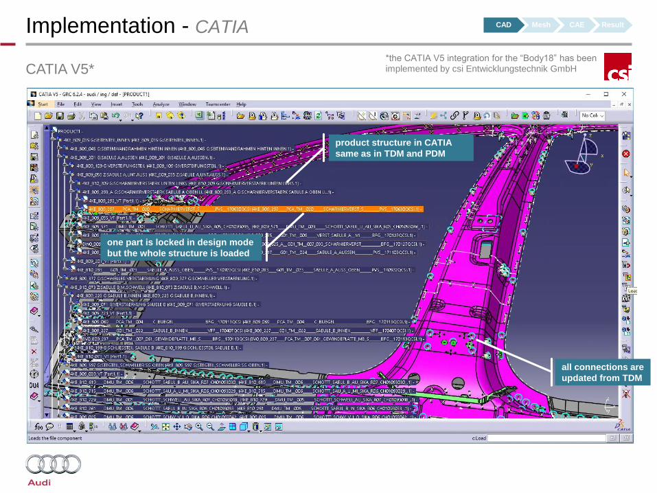
Implementation - CATIA
CATIA V5*
product structure in CATIA
same as in TDM and PDM
one part is locked in design mode
but the whole structure is loaded
all connections are
updated from TDM
*the CATIA V5 integration for the “Body18” has been implemented by csi Entwicklungstechnik GmbH
CAD Mesh CAE Result
■ Schweißpunkte, Schweißpunkte, …CAD Mesh CAE Result
Group 2
Group 3
Group 1
Part 1
CATPart
Part 2
CATPart
Part 3
CATPart
Part 4
CATPart
Part 2
CATPart
ANSA DB
Mesh PAMCRASH
Mesh LS-DYNA
Mesh Nastran
. . . . .
Part 5
CATPart
ANSA DB
Mesh PAMCRASH
Mesh LS-DYNA
. . . . .
Include A
. . . . .
Include B
Include C
Include D
. . . . .
Simulation 1
Simulation 2
Simulation 3
Simulation 4
Simulation 5
Simulation 6
Simulation 7
. . . . .
Connection 1: Part 1 – Part 2
Connection 2: Part 1 – Part 2
Connection 3: Part 1 – Part 2
…
Connection 1: Part 1 – Part 2
Connection 2: Part 1 – Part 2
Connection 3: Part 1 – Part 2
…
Connection 1: Part 1 – Part 2
Connection 2: Part 1 – Part 2
Connection 3: Part 1 – Part 2
…
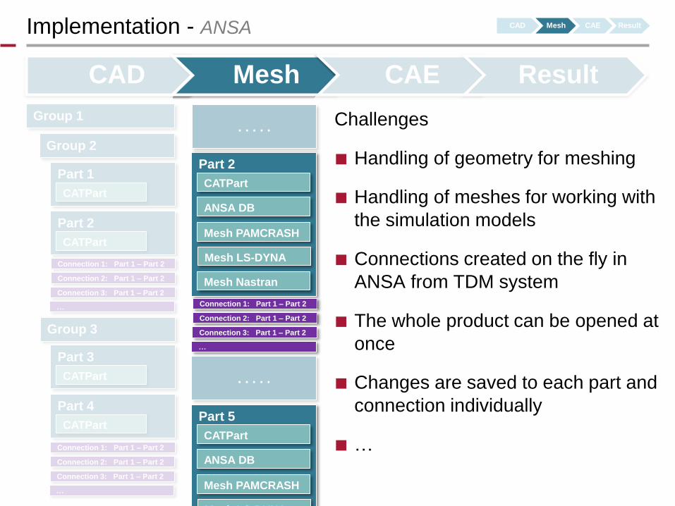
Implementation - ANSA
Challenges
■ Handling of geometry for meshing
■ Handling of meshes for working with
the simulation models
■ Connections created on the fly in
ANSA from TDM system
■ The whole product can be opened at
once
■ Changes are saved to each part and
connection individually
■ …
CAD Mesh CAE Result
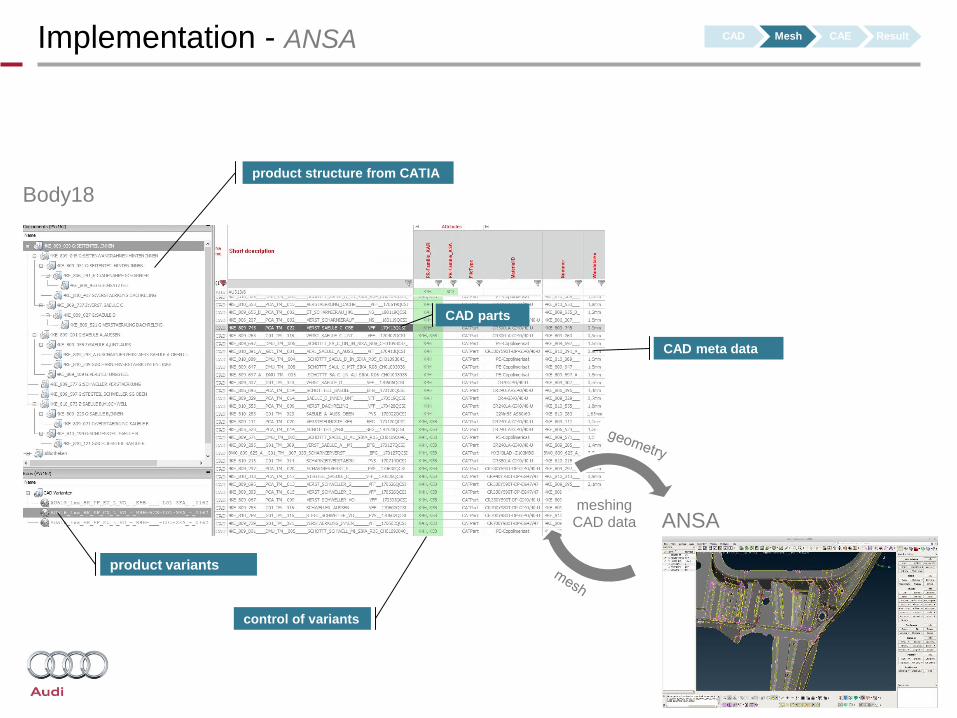
Implementation - ANSA
product structure from CATIA
CAD parts
CAD meta data
product variants
meshingCAD data ANSA
Body18
control of variants
CAD Mesh CAE Result
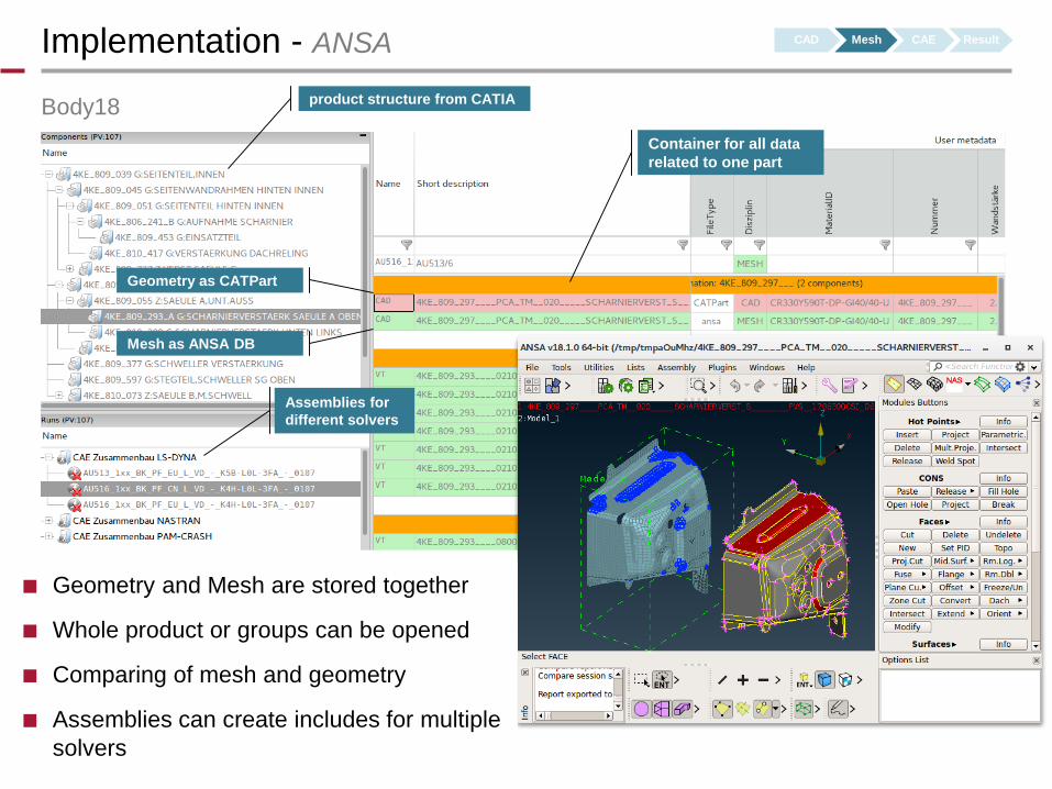
Implementation - ANSA
Body18
Geometry as CATPart
product structure from CATIA
Mesh as ANSA DB
■ Geometry and Mesh are stored together
■ Whole product or groups can be opened
■ Comparing of mesh and geometry
■ Assemblies can create includes for multiple
solvers
Container for all data
related to one part
Assemblies for
different solvers
CAD Mesh CAE Result
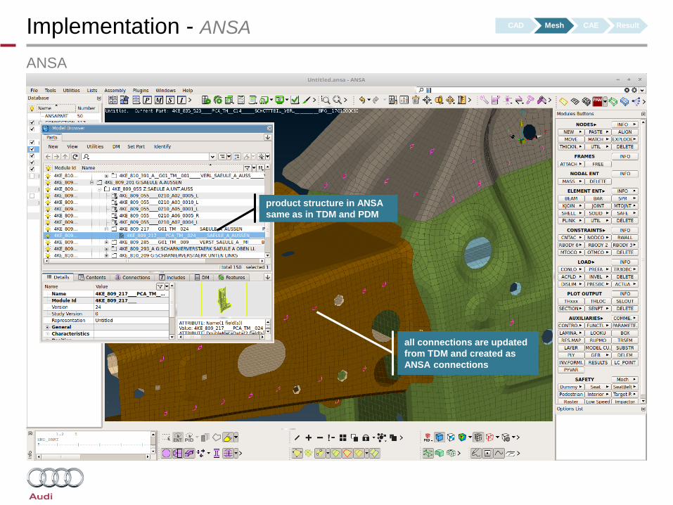
Implementation - ANSA
ANSA
all connections are updated
from TDM and created as
ANSA connections
product structure in ANSA
same as in TDM and PDM
CAD Mesh CAE Result
■ Schweißpunkte, Schweißpunkte, …CAD Mesh CAE Result
Group 2
Group 3
Group 1
Part 1
CATPart
Part 2
CATPart
Part 3
CATPart
Part 4
CATPart
Part 2
CATPart
ANSA DB
Mesh PAMCRASH
Mesh LS-DYNA
Mesh Nastran
. . . . .
Part 5
CATPart
ANSA DB
Mesh PAMCRASH
Mesh LS-DYNA
. . . . .
Include A
. . . . .
Include B
Include C
Include D
. . . . .
Simulation 1
Simulation 2
Simulation 3
Simulation 4
Simulation 5
Simulation 6
Simulation 7
. . . . .
Connection 1: Part 1 – Part 2
Connection 2: Part 1 – Part 2
Connection 3: Part 1 – Part 2
…
Connection 1: Part 1 – Part 2
Connection 2: Part 1 – Part 2
Connection 3: Part 1 – Part 2
…
Connection 1: Part 1 – Part 2
Connection 2: Part 1 – Part 2
Connection 3: Part 1 – Part 2
…
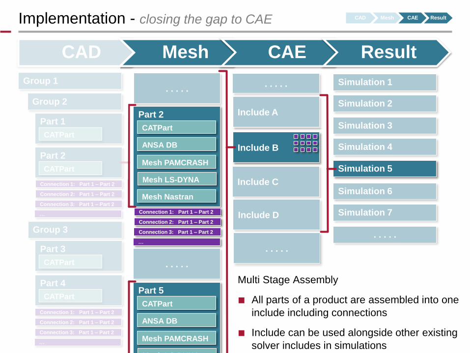
Multi Stage Assembly
■ All parts of a product are assembled into one
include including connections
■ Include can be used alongside other existing
solver includes in simulations
Implementation - closing the gap to CAE CAD Mesh CAE Result

CAD
Implementation - closing the gap to CAE
Assemblies for different solvers
create as result solver include files.
ANSA is used in batch to create the
includes and connections are
realized according to the needs of
the simulation.
Includes for different product variants are
created from the same data
CAECAD body in white pool
mounted in simulation pool
The result of the assembled CAD
data (RunOutputComponent) is used as
a solver include in simulations.
The solver include is directly linked
to the CAD assembly and gets
updated if CAD data changes.
Simulations for different product
variants, solvers and disciplines can
be set up based on the same CAD
and MESH data.
CAD Mesh CAE Result
ANSA
working on the
simulation model
Working with simulation models in ANSA
occurs on same meshes and CAD data
■ Schweißpunkte, Schweißpunkte, …CAD Mesh CAE Result
Group 2
Group 3
Group 1
Part 1
CATPart
Part 2
CATPart
Part 3
CATPart
Part 4
CATPart
Part 2
CATPart
ANSA DB
Mesh PAMCRASH
Mesh LS-DYNA
Mesh Nastran
. . . . .
Part 5
CATPart
ANSA DB
Mesh PAMCRASH
Mesh LS-DYNA
. . . . .
Include A
. . . . .
Include B
Include C
Include D
. . . . .
Simulation 1
Simulation 2
Simulation 3
Simulation 4
Simulation 5
Simulation 6
Simulation 7
. . . . .
Connection 1: Part 1 – Part 2
Connection 2: Part 1 – Part 2
Connection 3: Part 1 – Part 2
…
Connection 1: Part 1 – Part 2
Connection 2: Part 1 – Part 2
Connection 3: Part 1 – Part 2
…
Connection 1: Part 1 – Part 2
Connection 2: Part 1 – Part 2
Connection 3: Part 1 – Part 2
…
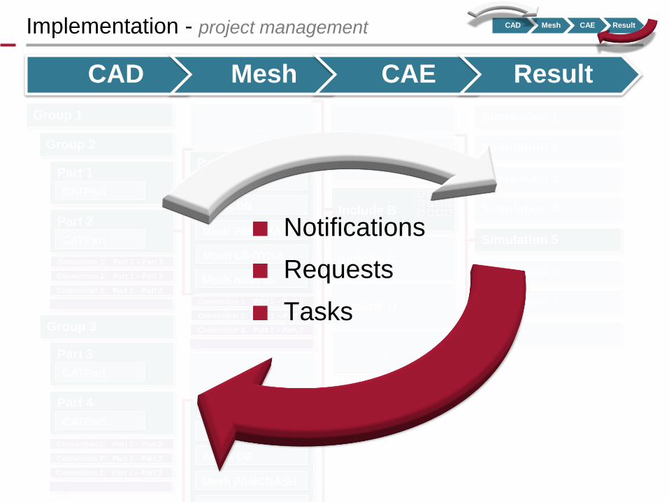
Implementation - project management CAD Mesh CAE Result
■ Notifications
■ Requests
■ Tasks
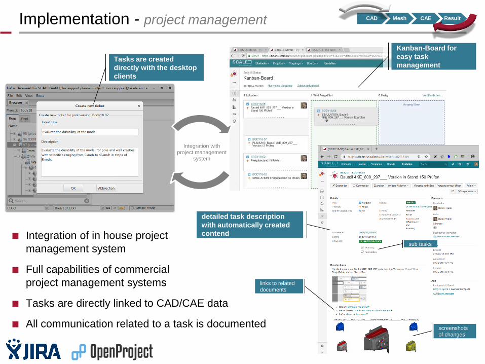
■ Integration of in house project
management system
■ Full capabilities of commercial
project management systems
■ Tasks are directly linked to CAD/CAE data
■ All communication related to a task is documented
Implementation - project management
Integration with project management
system
Tasks are created
directly with the desktop
clients
detailed task description
with automatically created
contend
links to related
documents
screenshots
of changes
sub tasks
Kanban-Board for
easy task
management
CAD Mesh CAE Result
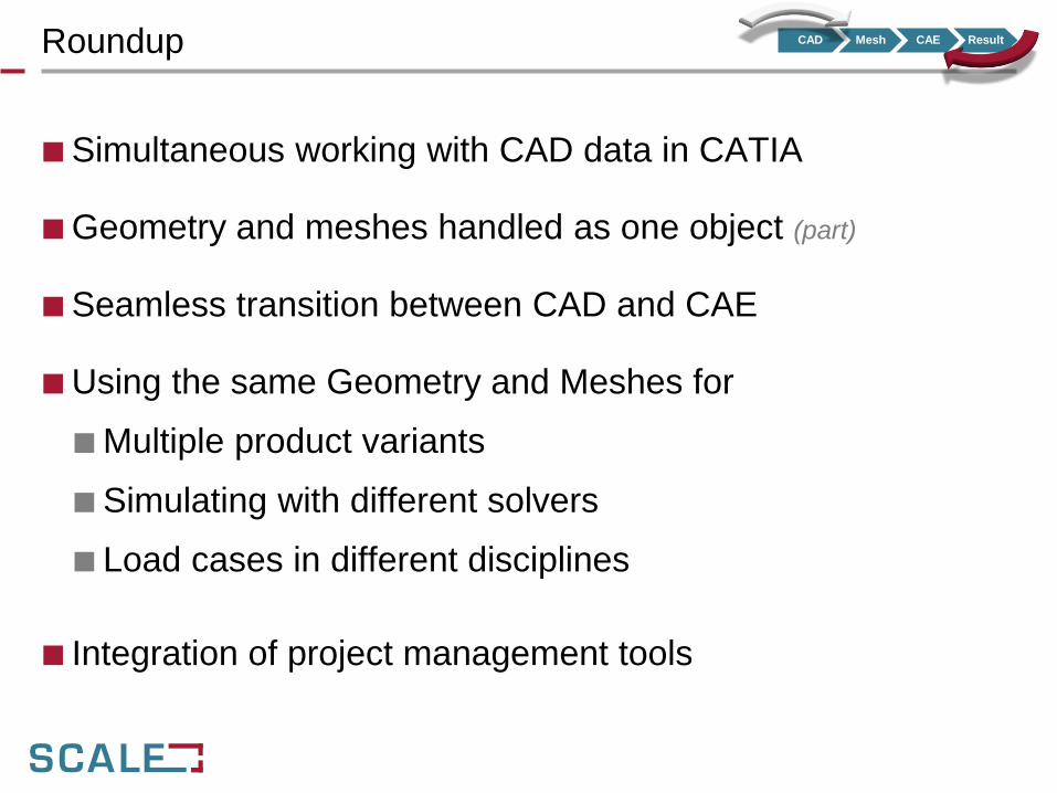
Roundup
■ Simultaneous working with CAD data in CATIA
■ Geometry and meshes handled as one object (part)
■ Seamless transition between CAD and CAE
■ Using the same Geometry and Meshes for
■ Multiple product variants
■ Simulating with different solvers
■ Load cases in different disciplines
■ Integration of project management tools
CAD Mesh CAE Result
so long, and thanks for all the fish…


![[CAD CAM CAE] Ansys - Userguide](https://img.pdfslide.us/doc/110x75/543e0826b1af9f1f2b8b45c7/cad-cam-cae-ansys-userguide.jpg)