Embed Size (px)
Citation preview

IIAEM, Propulsion‐I 13‐Aug‐15
Notes by Dr.Allamaprabhu C.Y. 1
Propulsion
The word propulsion is derived from two Latin words:
promeaning before or forward
pelleremeaning to push or drive.
• Propulsion means to push or drive forward an object.
Propulsion‐I www.Vidyarthiplus.com
www.Vidyarthiplus.com
www.Vidyarthiplus.com
IIAEM, Propulsion‐I 13‐Aug‐15
Notes by Dr.Allamaprabhu C.Y. 2
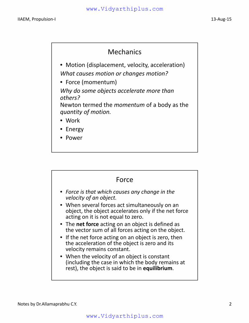
Mechanics
• Motion (displacement, velocity, acceleration)
What causes motion or changes motion?
• Force (momentum)
Why do some objects accelerate more than others?Newton termed the momentum of a body as the quantity of motion.
• Work
• Energy
• Power
Force
• Force is that which causes any change in the velocity of an object.
• When several forces act simultaneously on an object, the object accelerates only if the net force acting on it is not equal to zero.
• The net force acting on an object is defined as the vector sum of all forces acting on the object.
• If the net force acting on an object is zero, then the acceleration of the object is zero and its velocity remains constant.
• When the velocity of an object is constant (including the case in which the body remains at rest), the object is said to be in equilibrium.
www.Vidyarthiplus.com
www.Vidyarthiplus.com
IIAEM, Propulsion‐I 13‐Aug‐15
Notes by Dr.Allamaprabhu C.Y. 3
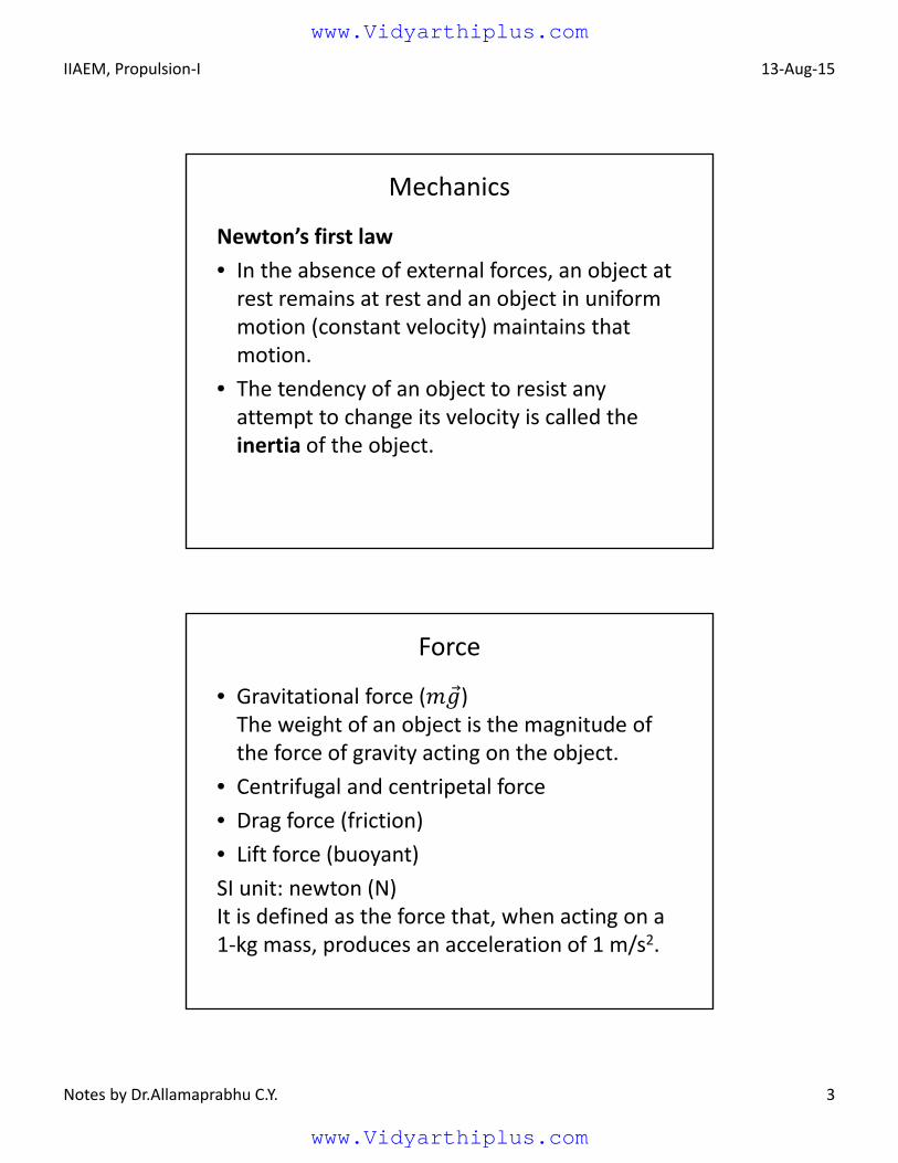
Mechanics
Newton’s first law
• In the absence of external forces, an object at rest remains at rest and an object in uniform motion (constant velocity) maintains that motion.
• The tendency of an object to resist any attempt to change its velocity is called the inertia of the object.
Force
• Gravitational force ( )The weight of an object is the magnitude of the force of gravity acting on the object.
• Centrifugal and centripetal force
• Drag force (friction)
• Lift force (buoyant)
SI unit: newton (N)It is defined as the force that, when acting on a 1‐kg mass, produces an acceleration of 1 m/s2.
www.Vidyarthiplus.com
www.Vidyarthiplus.com
IIAEM, Propulsion‐I 13‐Aug‐15
Notes by Dr.Allamaprabhu C.Y. 4
System versus Control Volume
• All the laws of mechanics and thermodynamics are written for a system, which is defined as an arbitrary quantity of matter upon which attention is fixed in the analysis of a problem.
• Everything external to this system is called surroundings, and the system is separated from its surroundings by its boundaries.
• For fluid flow problems one wishes to study a region through which fluid is flowing rather than fix one’s attention upon a fixed quantity of mass.
• The region fixed in space is called an open system or a control volume. A control volume is any prescribed volume in space bounded by a control surface across which matter may flow and energy interactions (heat and work transfer) may occur.
www.Vidyarthiplus.com
www.Vidyarthiplus.com
IIAEM, Propulsion‐I 13‐Aug‐15
Notes by Dr.Allamaprabhu C.Y. 5
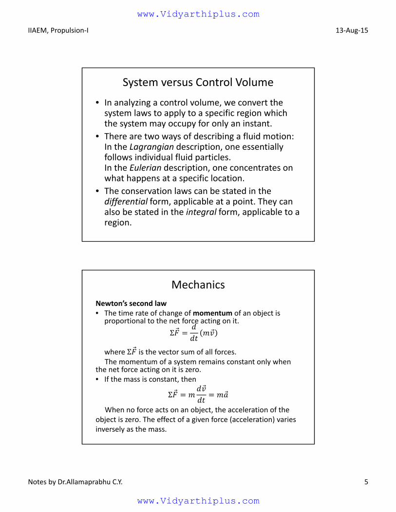
System versus Control Volume
• In analyzing a control volume, we convert the system laws to apply to a specific region which the system may occupy for only an instant.
• There are two ways of describing a fluid motion:In the Lagrangian description, one essentially follows individual fluid particles.In the Eulerian description, one concentrates on what happens at a specific location.
• The conservation laws can be stated in the differential form, applicable at a point. They can also be stated in the integral form, applicable to a region.
Mechanics
Newton’s second law• The time rate of change of momentum of an object is
proportional to the net force acting on it.
Σ
where Σ is the vector sum of all forces.The momentum of a system remains constant only when
the net force acting on it is zero. • If the mass is constant, then
Σ
When no force acts on an object, the acceleration of the object is zero. The effect of a given force (acceleration) varies inversely as the mass.
www.Vidyarthiplus.com
www.Vidyarthiplus.com
IIAEM, Propulsion‐I 13‐Aug‐15
Notes by Dr.Allamaprabhu C.Y. 6
Mechanics
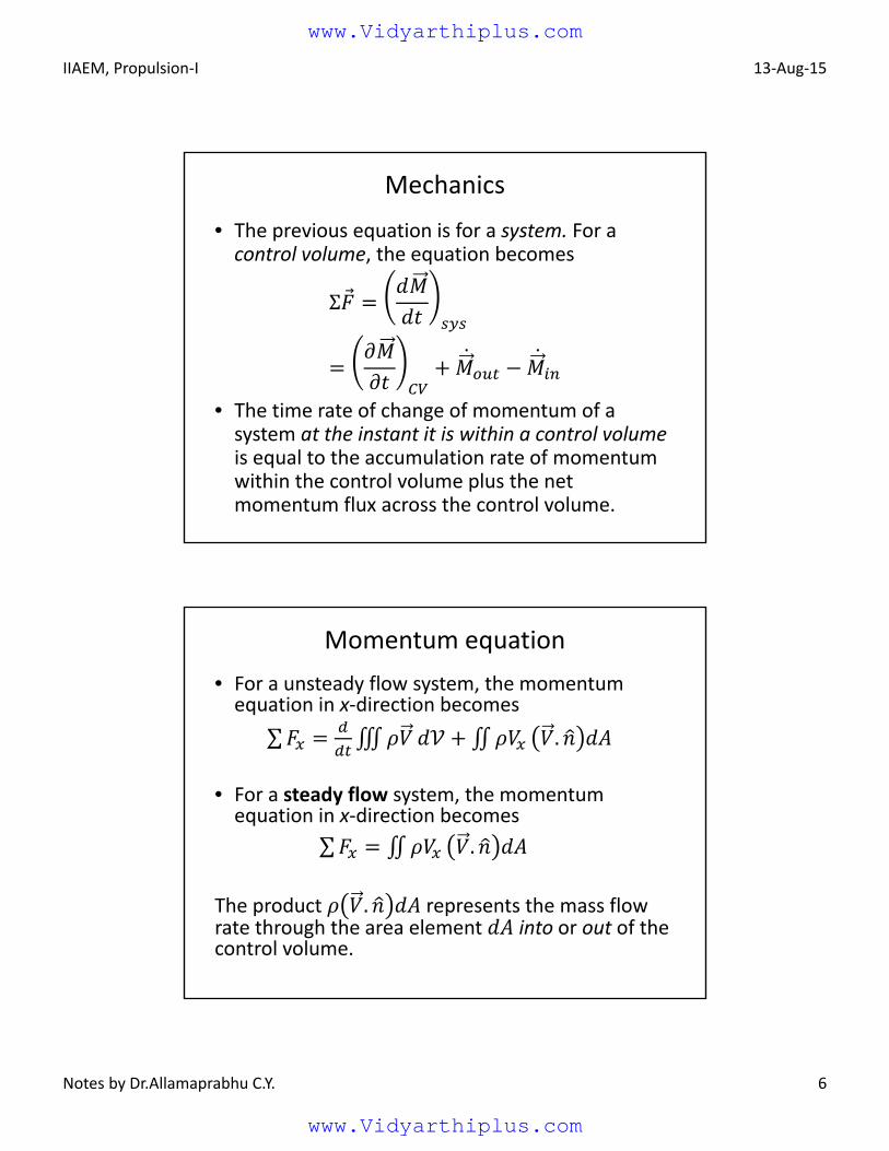
• The previous equation is for a system. For a control volume, the equation becomes
Σ
• The time rate of change of momentum of a system at the instant it is within a control volumeis equal to the accumulation rate of momentum within the control volume plus the net momentum flux across the control volume.
Momentum equation
• For a unsteady flow system, the momentum equation in x‐direction becomes
∑ ∭ ∬ .
• For a steady flow system, the momentum equation in x‐direction becomes
∑ ∬ .
The product . represents the mass flow rate through the area element into or out of the control volume.
www.Vidyarthiplus.com
www.Vidyarthiplus.com
IIAEM, Propulsion‐I 13‐Aug‐15
Notes by Dr.Allamaprabhu C.Y. 7
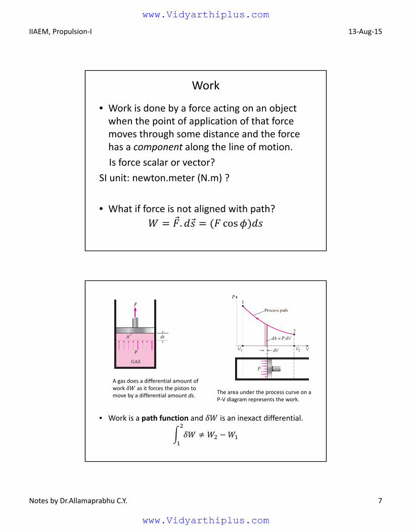
Work
• Work is done by a force acting on an object when the point of application of that force moves through some distance and the force has a component along the line of motion.
Is force scalar or vector?
SI unit: newton.meter (N.m) ?
• What if force is not aligned with path?
. cos
A gas does a differential amount ofwork as it forces the piston tomove by a differential amount ds.
The area under the process curve on aP‐V diagram represents the work.
• Work is a path function and is an inexact differential.
www.Vidyarthiplus.com
www.Vidyarthiplus.com
IIAEM, Propulsion‐I 13‐Aug‐15
Notes by Dr.Allamaprabhu C.Y. 8
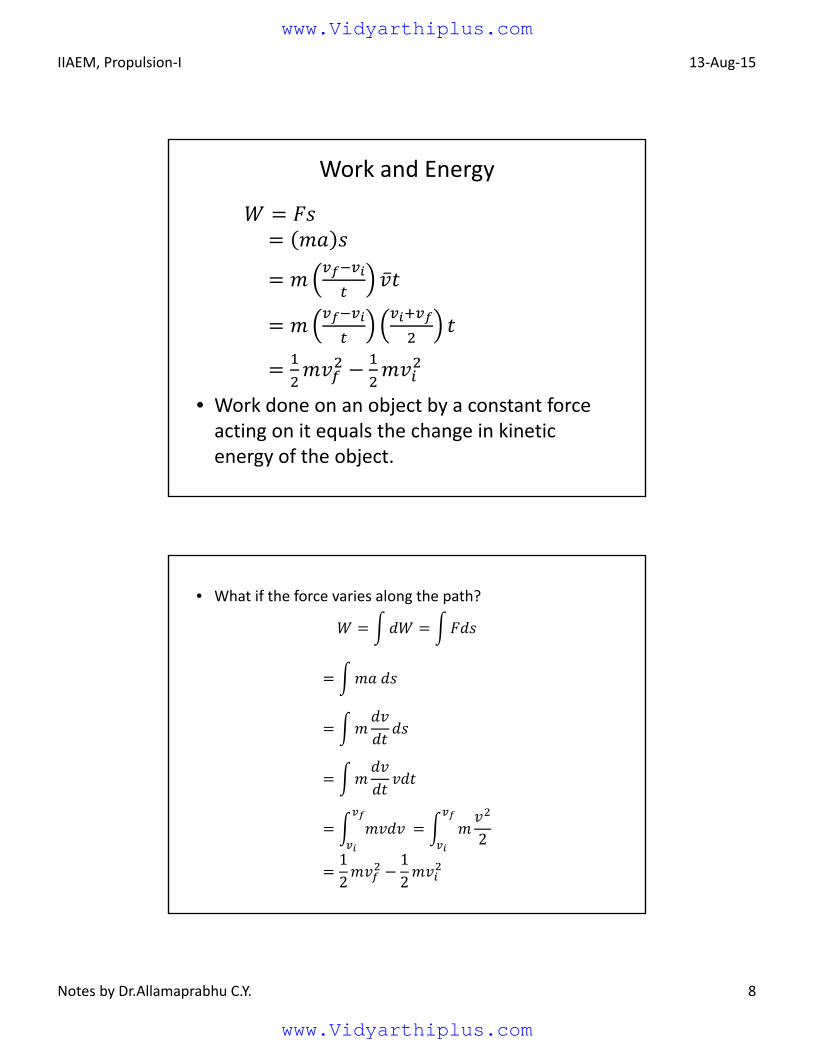
Work and Energy
• Work done on an object by a constant force acting on it equals the change in kinetic energy of the object.
• What if the force varies along the path?
2
12
12
www.Vidyarthiplus.com
www.Vidyarthiplus.com

IIAEM, Propulsion‐I 13‐Aug‐15
Notes by Dr.Allamaprabhu C.Y. 9
Energy
• Work is energy transferred by force; if energy is transferred to the system (object), work is positive; if energy is transferred from the system, work is negative.
• Energy is ability to do work. The state of a system can be changed by adding or extracting energy.
SI unit is joule.
• When an object is accelerated, work is done against inertia, such that the work equals change in kinetic energy of the object.
• Kinetic energy is a form of energy associated with the motion of an object with mass .
Energy
• Mechanical energy is defined as the form of energy that can be converted to mechanical work completely.
• It is the sum of kinetic energy and potential energy.
• Thermal energy is not mechanical energy since it cannot be converted to work completely (Second law of thermodynamics).
• A pump transfers mechanical energy to a fluid by raising its pressure, and a turbine extracts mechanical energy from a fluid by dropping its pressure. Therefore, the pressure of a flowing fluid is also associated with its mechanical energy.
www.Vidyarthiplus.com
www.Vidyarthiplus.com
IIAEM, Propulsion‐I 13‐Aug‐15
Notes by Dr.Allamaprabhu C.Y. 10
Energy
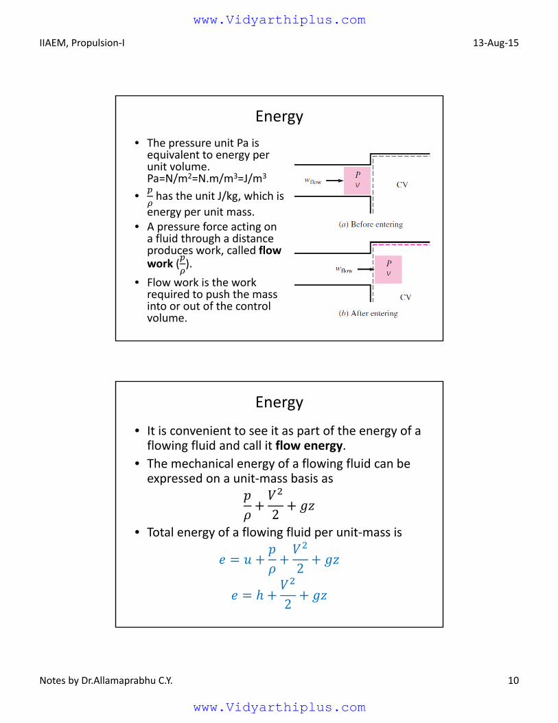
• The pressure unit Pa is equivalent to energy per unit volume.Pa=N/m2=N.m/m3=J/m3
• has the unit J/kg, which is
energy per unit mass.• A pressure force acting on a fluid through a distance produces work, called flow work ( ).
• Flow work is the work required to push the mass into or out of the control volume.
Energy
• It is convenient to see it as part of the energy of a flowing fluid and call it flow energy.
• The mechanical energy of a flowing fluid can be expressed on a unit‐mass basis as
2• Total energy of a flowing fluid per unit‐mass is
2
2
www.Vidyarthiplus.com
www.Vidyarthiplus.com
IIAEM, Propulsion‐I 13‐Aug‐15
Notes by Dr.Allamaprabhu C.Y. 11
Energy equation
• The First law of thermodynamics(Conservation of energy)
• For a steady‐flow system
0
2 2
• Energy can be transferred by heat, work and mass.
0
Power
• From a practical viewpoint, it is interesting to know not only the work done but also the rate at which it is done.
• The time rate of doing work is called power.
• If an external force is applied to an object, and if the work done by this force in the time interval Δ is , then the average power expended during this interval is defined as
≡Δ
• Since the work done on the object contributes to the increase in the energy of the object, a more general definition of power is the time rate of energy transfer.
www.Vidyarthiplus.com
www.Vidyarthiplus.com
IIAEM, Propulsion‐I 13‐Aug‐15
Notes by Dr.Allamaprabhu C.Y. 12
Power
• Since the work done on the object contributes to the increase in the energy of the object, a more general definition of power is the time rate of energy transfer.
• Instantaneous power is the limiting value of the average power as ∆ approaches zero:
lim∆ → ∆. .
SI unit: joules per second (J/s), also called watt (W).
Efficiency
• Thermal efficiency is defined as the ratio of the rate of net work output of the engine to the rate of heat input to the working fluid
,
• The conversion of thermal energy to mechanical energy is subject to the laws of thermodynamics.
• These laws determine an upper limit on the thermal efficiency that depends only on the temperatures at which heat is added to and rejected from the working fluid of the engine.
www.Vidyarthiplus.com
www.Vidyarthiplus.com
IIAEM, Propulsion‐I 13‐Aug‐15
Notes by Dr.Allamaprabhu C.Y. 13
Efficiency
• Most engines use the atmosphere as a heat sink, so usually the minimum available heat‐rejection temperature is the atmosphere temperature denoted by .
• The maximum available heat‐addition temperature is in principle limited only by the characteristics of the combustion process. In practice it is usually limited by the temperature capabilities of materials.
• If this maximum heat‐addition temperature is denoted by , the maximum possible thermal efficiency is that of a Carnot cycle operating between these temperature extremes.
1
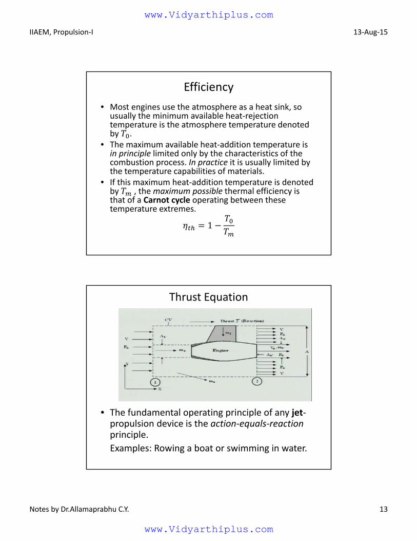
Thrust Equation
• The fundamental operating principle of any jet‐propulsion device is the action‐equals‐reaction principle.
Examples: Rowing a boat or swimming in water.
www.Vidyarthiplus.com
www.Vidyarthiplus.com
IIAEM, Propulsion‐I 13‐Aug‐15
Notes by Dr.Allamaprabhu C.Y. 14
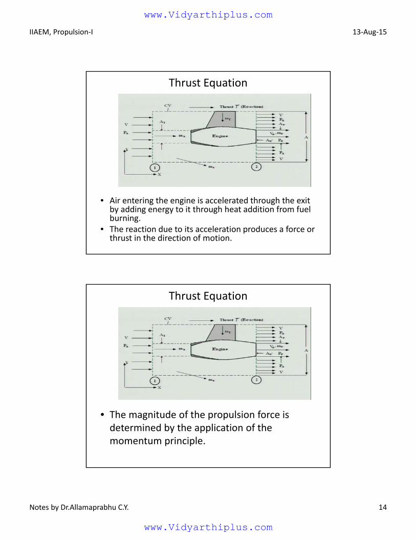
Thrust Equation
• Air entering the engine is accelerated through the exit by adding energy to it through heat addition from fuel burning.
• The reaction due to its acceleration produces a force or thrust in the direction of motion.
Thrust Equation
• The magnitude of the propulsion force is determined by the application of the momentum principle.
www.Vidyarthiplus.com
www.Vidyarthiplus.com
IIAEM, Propulsion‐I 13‐Aug‐15
Notes by Dr.Allamaprabhu C.Y. 15
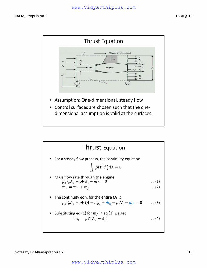
Thrust Equation
• Assumption: One‐dimensional, steady flow
• Control surfaces are chosen such that the one‐dimensional assumption is valid at the surfaces.
Thrust Equation
• For a steady flow process, the continuity equation
. 0
• Mass flow rate through the engine:0 … (1)
… (2)
• The continuity eqn. for the entire CV is
0 … (3)
• Substituting eq (1) for in eq (3) we get… (4)
www.Vidyarthiplus.com
www.Vidyarthiplus.com
IIAEM, Propulsion‐I 13‐Aug‐15
Notes by Dr.Allamaprabhu C.Y. 16
• The momentum equation in x‐direction becomes
∑ ∬ . … (5)
• Neglecting body forces,
∑ ∬
…(6)
and
∬ .… (7)
Thrust Equation
• Substituting Eq.(4) for , we get
∬ . … (8)
• Substituting Eqs. (6) and (8) in Eq. (5)
… (9)
• Substituting Eq.(2) for , we get1
where /
Thrust Equation
momentum thrust pressure thrust
www.Vidyarthiplus.com
www.Vidyarthiplus.com
IIAEM, Propulsion‐I 13‐Aug‐15
Notes by Dr.Allamaprabhu C.Y. 17
• Specific thrust is the thrust per unit mass flow rate of air (N.s/kg). It indicates the relative size of engines producing the same thrust because the dimensions of the engine are primarily determined by the airflow.
Size is important because it not only means weight but also the frontal area and the consequent drag (ram drag, ).
• Thrust specific fuel consumption (TSFC) is the fuel consumption rate per unit thrust (kg/N.hr).
One method of comparing engines is on the basis of their TSFC at various thrust settings and flight conditions.
TSFC and specific thrust are related by/
Performance parameter
Working principle
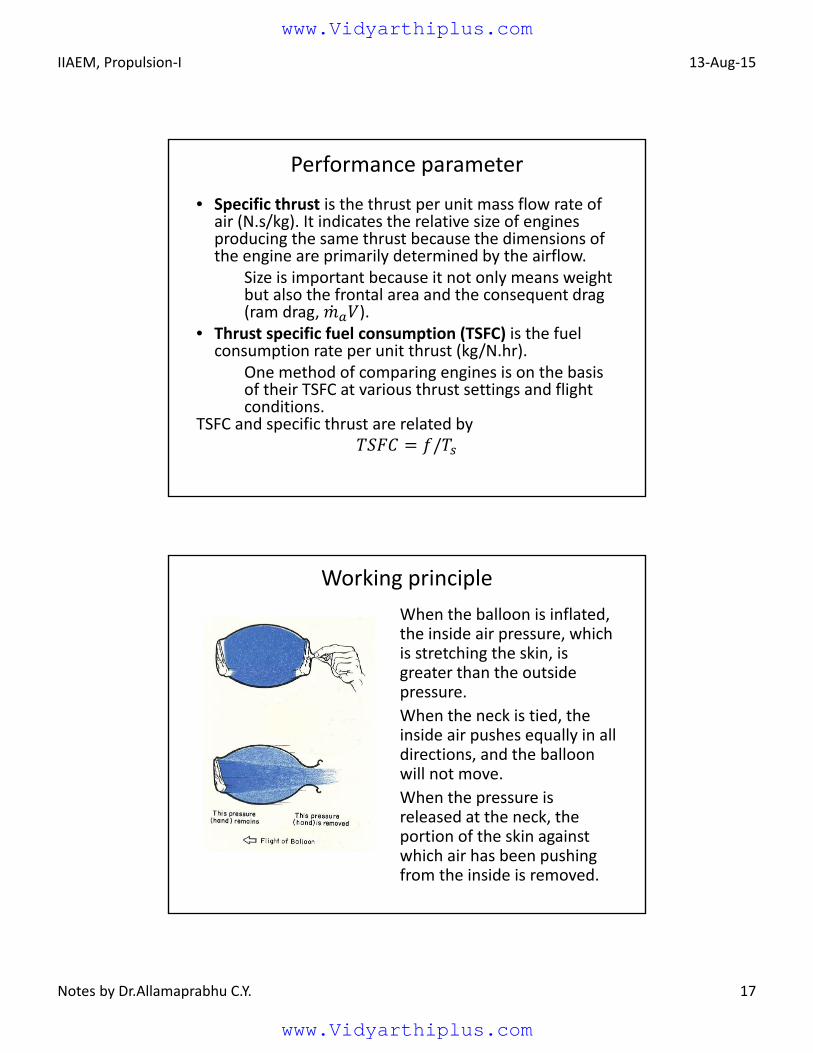
When the balloon is inflated, the inside air pressure, which is stretching the skin, is greater than the outside pressure.
When the neck is tied, the inside air pushes equally in all directions, and the balloon will not move.
When the pressure is released at the neck, the portion of the skin against which air has been pushing from the inside is removed.
www.Vidyarthiplus.com
www.Vidyarthiplus.com
IIAEM, Propulsion‐I 13‐Aug‐15
Notes by Dr.Allamaprabhu C.Y. 18
Working principle
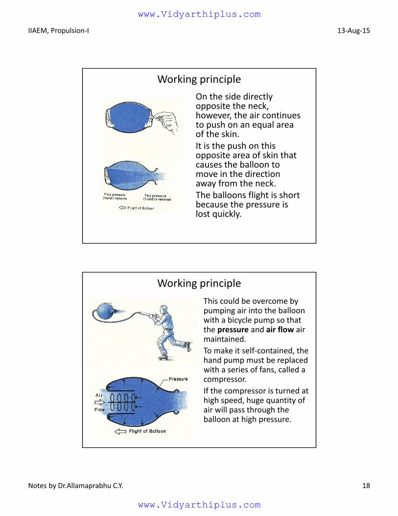
On the side directly opposite the neck, however, the air continues to push on an equal area of the skin.It is the push on this opposite area of skin that causes the balloon to move in the direction away from the neck.The balloons flight is short because the pressure is lost quickly.
Working principle
This could be overcome by pumping air into the balloon with a bicycle pump so that the pressure and air flow air maintained.
To make it self‐contained, the hand pump must be replaced with a series of fans, called a compressor.
If the compressor is turned at high speed, huge quantity of air will pass through the balloon at high pressure.
www.Vidyarthiplus.com
www.Vidyarthiplus.com
IIAEM, Propulsion‐I 13‐Aug‐15
Notes by Dr.Allamaprabhu C.Y. 19
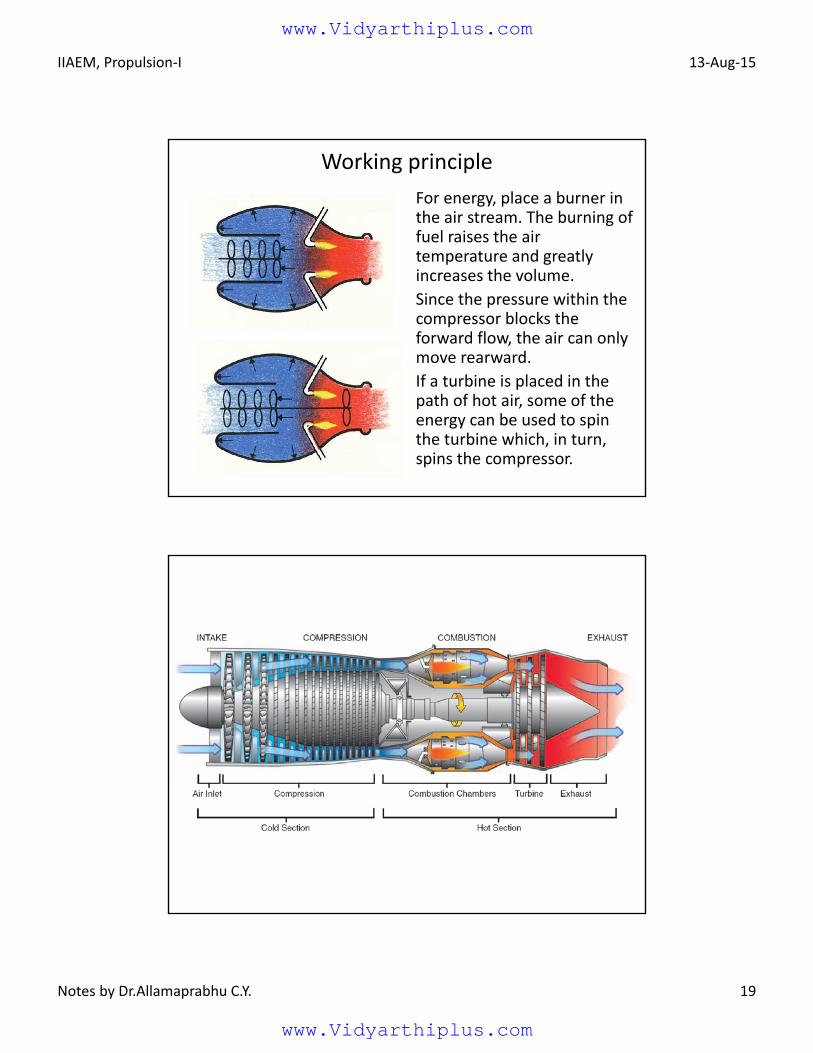
Working principle
For energy, place a burner in the air stream. The burning of fuel raises the air temperature and greatly increases the volume.
Since the pressure within the compressor blocks the forward flow, the air can only move rearward.
If a turbine is placed in the path of hot air, some of the energy can be used to spin the turbine which, in turn, spins the compressor.
www.Vidyarthiplus.com
www.Vidyarthiplus.com
IIAEM, Propulsion‐I 13‐Aug‐15
Notes by Dr.Allamaprabhu C.Y. 20
Cycle analysis
Cycle analysis is the study of the thermodynamic changes of the working fluid (air and products of combustion) as it flows through the engine, without regard for the mechanical means used to effect its motion.
• Rather than deal with the components (inlet, compressor, turbine) themselves, we characterize them by the change in properties they produce.
For example, the compressor is described by a stagnation pressure ratio and efficiency.
Cycle analysis
The main purpose of cycle analysis is to determine the values of design choice (e.g., compressor pressure ratio) and design limit (e.g. combustor exit temperature) parameters.
A jet engine operates with an open cycle, which means fresh air is drawn into the compressor and the products are exhausted from the turbine and not reused.
www.Vidyarthiplus.com
www.Vidyarthiplus.com
IIAEM, Propulsion‐I 13‐Aug‐15
Notes by Dr.Allamaprabhu C.Y. 21
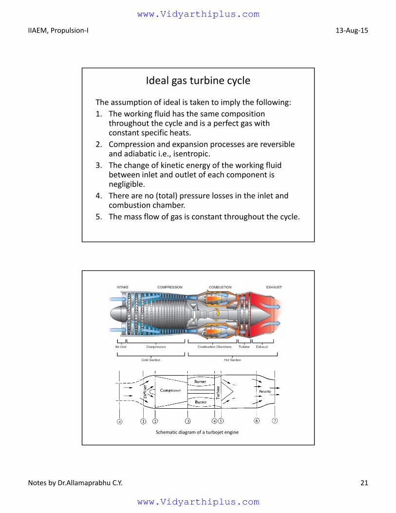
Ideal gas turbine cycle
The assumption of ideal is taken to imply the following:
1. The working fluid has the same composition throughout the cycle and is a perfect gas with constant specific heats.
2. Compression and expansion processes are reversible and adiabatic i.e., isentropic.
3. The change of kinetic energy of the working fluid between inlet and outlet of each component is negligible.
4. There are no (total) pressure losses in the inlet and combustion chamber.
5. The mass flow of gas is constant throughout the cycle.
Schematic diagram of a turbojet engine
www.Vidyarthiplus.com
www.Vidyarthiplus.com
IIAEM, Propulsion‐I 13‐Aug‐15
Notes by Dr.Allamaprabhu C.Y. 22
Cycle analysis
a
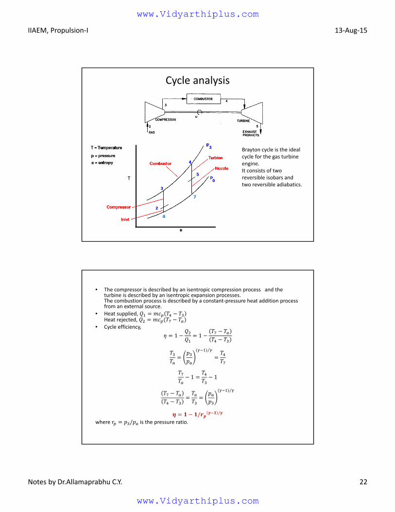
Brayton cycle is the ideal cycle for the gas turbine engine.It consists of two reversible isobars and two reversible adiabatics.
7
• The compressor is described by an isentropic compression process and the turbine is described by an isentropic expansion processes.The combustion process is described by a constant‐pressure heat addition process from an external source.
• Heat supplied, Heat rejected,
• Cycle efficiency,
1 1
⁄
1 1
⁄
/ /
where / is the pressure ratio.
www.Vidyarthiplus.com
www.Vidyarthiplus.com
IIAEM, Propulsion‐I 13‐Aug‐15
Notes by Dr.Allamaprabhu C.Y. 23
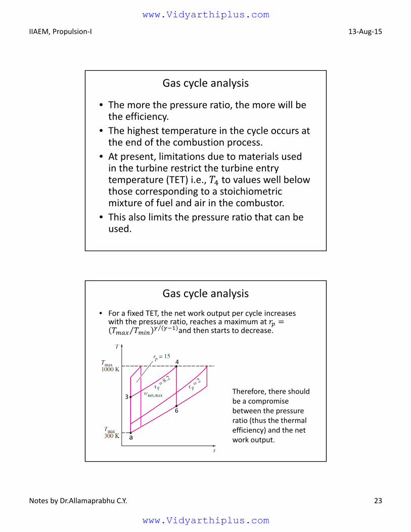
• The more the pressure ratio, the more will be the efficiency.
• The highest temperature in the cycle occurs at the end of the combustion process.
• At present, limitations due to materials used in the turbine restrict the turbine entry temperature (TET) i.e., to values well below those corresponding to a stoichiometric mixture of fuel and air in the combustor.
• This also limits the pressure ratio that can be used.
Gas cycle analysis
• For a fixed TET, the net work output per cycle increases with the pressure ratio, reaches a maximum at
⁄ ⁄ and then starts to decrease.
Gas cycle analysis
Therefore, there should be a compromise between the pressure ratio (thus the thermal efficiency) and the net work output.a
3
4
6
www.Vidyarthiplus.com
www.Vidyarthiplus.com
IIAEM, Propulsion‐I 13‐Aug‐15
Notes by Dr.Allamaprabhu C.Y. 24
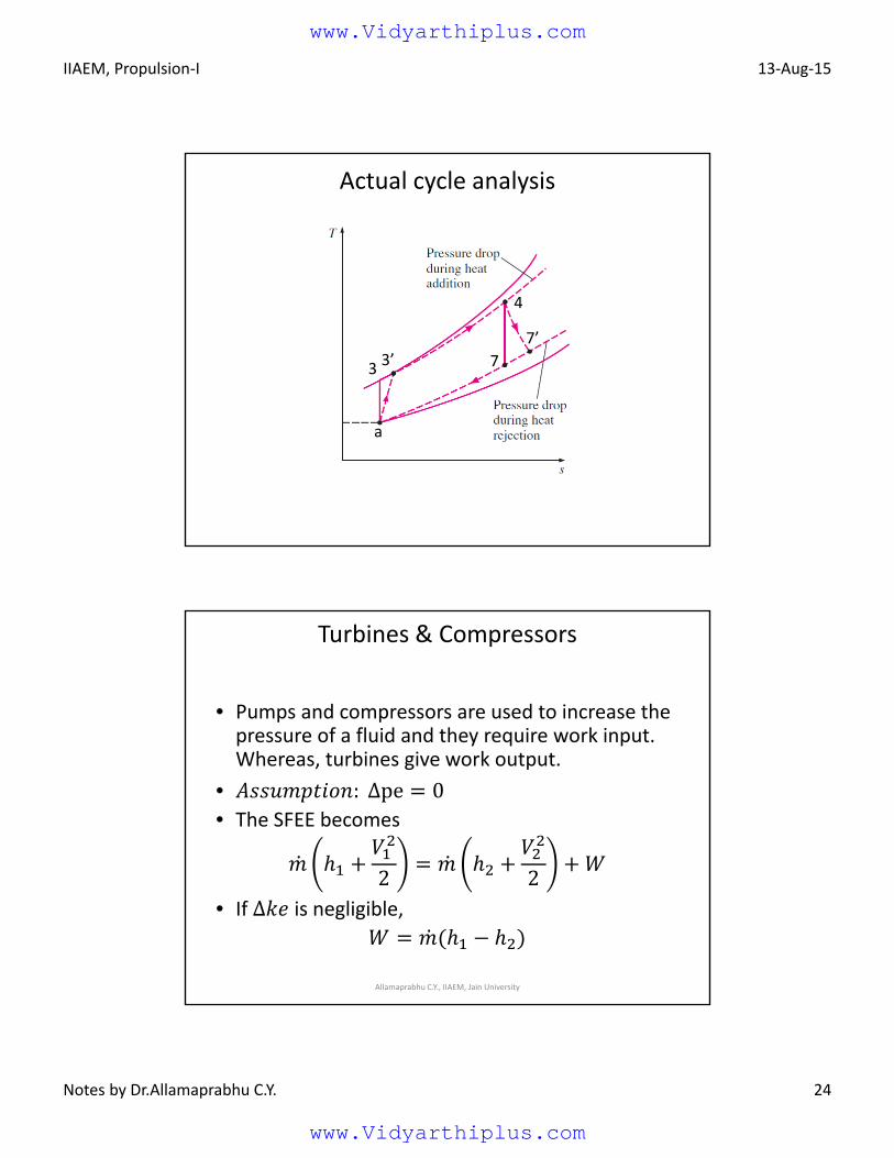
Actual cycle analysis
a
33’ 7
7’
4
Turbines & Compressors
• Pumps and compressors are used to increase the pressure of a fluid and they require work input. Whereas, turbines give work output.
• : ∆pe 0• The SFEE becomes
2 2• If ∆ is negligible,
Allamaprabhu C.Y., IIAEM, Jain University
www.Vidyarthiplus.com
www.Vidyarthiplus.com
IIAEM, Propulsion‐I 13‐Aug‐15
Notes by Dr.Allamaprabhu C.Y. 25
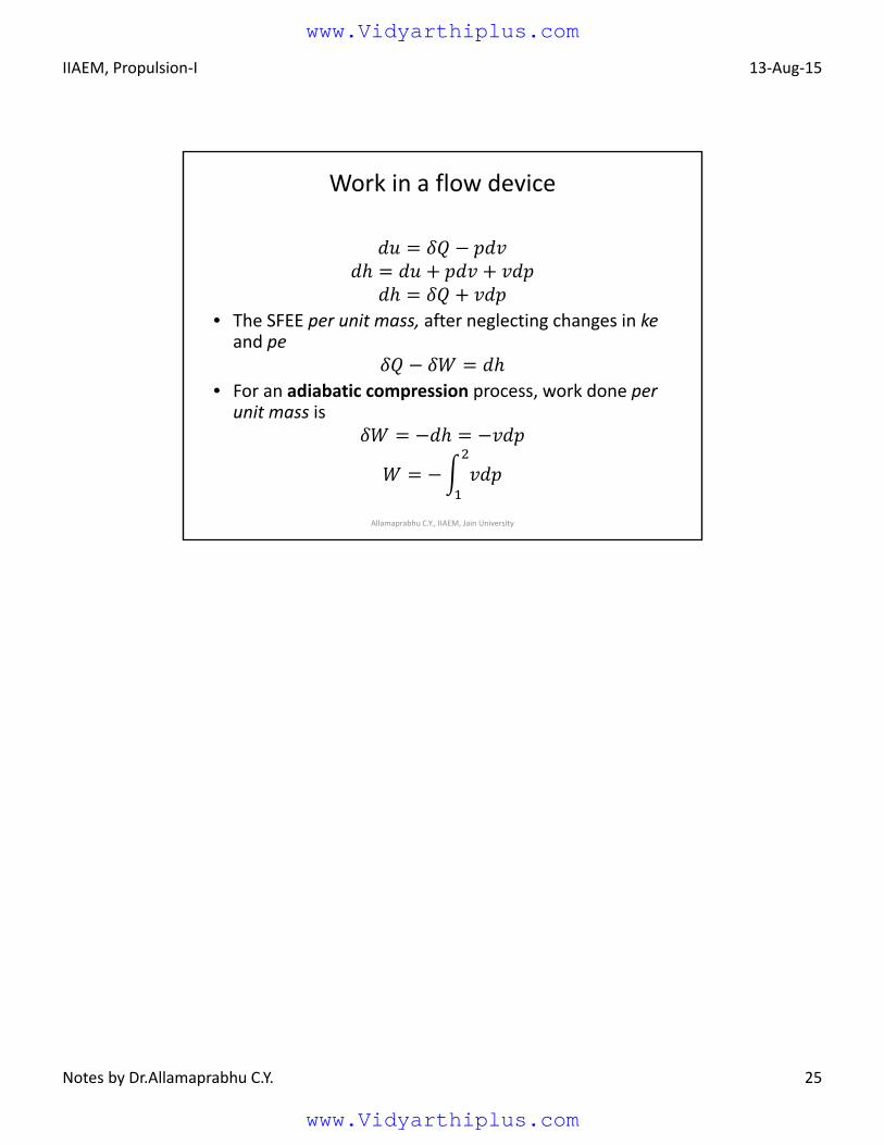
Work in a flow device
• The SFEE per unit mass, after neglecting changes in keand pe
• For an adiabatic compression process, work done per unit mass is
Allamaprabhu C.Y., IIAEM, Jain University
www.Vidyarthiplus.com
www.Vidyarthiplus.com
IIAEM, Jain University 9/1/2015
Lecture Notes by Dr. Allamaprabhu C.Y. 1
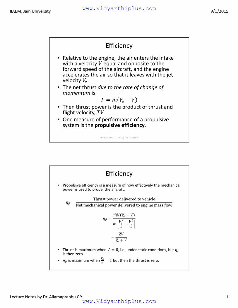
Efficiency
• Relative to the engine, the air enters the intake with a velocity equal and opposite to the forward speed of the aircraft, and the engine accelerates the air so that it leaves with the jet velocity .
• The net thrust due to the rate of change of momentum is
• Then thrust power is the product of thrust and flight velocity,
• One measure of performance of a propulsive system is the propulsive efficiency.
Allamaprabhu C.Y., IIAEM, Jain University
Efficiency
• Propulsive efficiency is a measure of how effectively the mechanical power is used to propel the aircraft.
ThrustpowerdeliveredtovehicleNetmechanicalpowerdeliveredtoenginemassflow
2 2
2
• Thrust is maximum when 0, i.e. under static conditions, but is then zero.
• is maximum when 1 but then the thrust is zero.
www.Vidyarthiplus.com
www.Vidyarthiplus.com
IIAEM, Jain University 9/1/2015
Lecture Notes by Dr. Allamaprabhu C.Y. 2
Efficiency
• For a given mass flow and a flight velocity, the thrust increases with / . Thus a definite tradeoff must be made between propulsive efficiency and thrust per unit mass flow.
• So we may conclude that although should be greater than the difference should not be too great. This is the reason for the development of the family of propulsion systems.
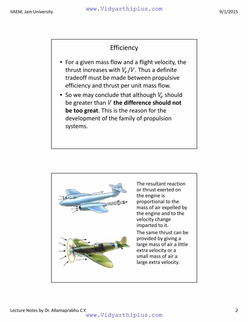
The resultant reaction or thrust exerted on the engine is proportional to the mass of air expelled by the engine and to the velocity change imparted to it.
The same thrust can be provided by giving a large mass of air a little extra velocity or a small mass of air a large extra velocity.
www.Vidyarthiplus.com
www.Vidyarthiplus.com
IIAEM, Jain University 9/1/2015
Lecture Notes by Dr. Allamaprabhu C.Y. 3
Efficiency
• Increased mass flow in general implies increased engine size and weight and it may also increase drag, so that there is a compromise to be struck between low overall engine size and high propulsive efficiency.
• The choice depends on the application, with relatively small values of propulsive efficiency appropriate to military fighter engines and comparatively high values for commercial transport engines.
www.Vidyarthiplus.com
www.Vidyarthiplus.com