Embed Size (px)
Citation preview

First Printing — August 1997
Copyright 1997NEC Computer Systems Division
Packard Bell NEC, Inc.1414 Massachusetts Avenue
Boxborough, MA 01709All Rights Reserved
Proprietary Notice and Liability Disclaimer
The information disclosed in this document, including all designs and related materials, is thevaluable property of NEC Computer Systems Division, Packard Bell NEC (NECCSD, PBNEC)and/or its licensors. NECCSD and/or its licensors, as appropriate, reserve all patent, copyrightand other proprietary rights to this document, including all design, manufacturing,reproduction, use, and sales rights thereto, except to the extent said rights are expressly grantedto others.
The NECCSD product(s) discussed in this document are warranted in accordance with theterms of the Warranty Statement accompanying each product. However, actual performance ofeach such product is dependent upon factors such as system configuration, customer data, andoperator control. Since implementation by customers of each product may vary, the suitabilityof specific product configurations and applications must be determined by the customer and isnot warranted by NECCSD.
To allow for design and specification improvements, the information in this document issubject to change at any time, without notice. Reproduction of this document or portionsthereof without prior written approval of NECCSD is prohibited.
NEC is a registered trademark of NEC Corporation and NEC CS500 is a trademark of NEC Technologies, Inc. These trademarks and registered trademarks are used under license by NEC Computer Systems Division,Packard Bell NEC, Inc.
All other product, brand, or trade names used in this publication are the trademarks or registered trademarks of theirrespective trademark owners.
Contents iii
Contents
System upgrades ........................................................................ 1 Choosing options..............................................................................2
Getting started..................................................................................2
Precautions.................................................................................. 3 Working inside the system................................................................4
Handling computer parts...................................................................4
Connecting/disconnecting cables.......................................................5
A look inside ................................................................................ 7 Taking off the cover.........................................................................8
Taking a quick look inside..............................................................11
Looking at the system board...........................................................12
Replacing the cover........................................................................13
System memory......................................................................... 15 Looking at memory upgrade kits.....................................................16
Checking the memory in your system..............................................17
Adding memory modules................................................................19
Removing a memory module...........................................................21
Expansion boards ..................................................................... 23 Adding boards................................................................................24
Removing a board...........................................................................28
iv Contents
System processor ......................................................................31 Removing the processor................................................................. 32
Adding a processor........................................................................ 35
Storage devices..........................................................................39 Preparing the device....................................................................... 40
Identifying the cables you need....................................................... 41
System power cables................................................................. 42
Diskette drive cable................................................................... 43
IDE cables................................................................................. 44
Connecting cables to your device................................................... 45
Cabling an IDE device............................................................... 45
Cabling a diskette drive............................................................. 47
Installing storage devices................................................................ 48
Adding a 3 1/2-inch hard disk.................................................... 48
Adding a 5 1/4-inch device........................................................ 52
External options .........................................................................59 Locating external connectors.......................................................... 60
Connecting an NEC CS500 monitor............................................... 64
Connecting an NEC C700 monitor................................................. 66
Connecting a printer....................................................................... 68
System resources ......................................................................71 Looking at communication ports.................................................... 72
Looking at COM port and IRQ settings ......................................... 72
Viewing system resources.............................................................. 73
Checking jumper settings............................................................... 74
Clearing your password.................................................................. 77
Contents v
System specifications............................................................... 79 System chassis................................................................................80
Power supply.............................................................................80
Expansion board slots................................................................81
Storage device slots...................................................................81
System unit dimensions and weight............................................81
System board..................................................................................82
Processor ...................................................................................83
Secondary cache........................................................................84
System memory..........................................................................84
Intel TX PCI chipset..................................................................85
PCI local bus..............................................................................86
Expansion board slots................................................................87
BIOS .........................................................................................87
IDE ports...................................................................................88
I/O ports and connectors............................................................88
Universal serial bus....................................................................89
Graphics accelerator...................................................................90
Power management....................................................................91
Plug and play.............................................................................91
Feature connector ......................................................................92
Diskette drive.................................................................................92
Hard disk........................................................................................93
CD-ROM reader.............................................................................94
Keyboard........................................................................................97
Mouse ............................................................................................98
Fax/modem/sound board.................................................................98
Sound ........................................................................................99
Fax/modem..............................................................................101
Graphics board.............................................................................102

vi Contents
Ethernet network board ............................................................... 103
Game pad.................................................................................... 104
Environmental specifications........................................................ 104
Tables Diskette drive specifications........................................................... 92
CD-ROM reader specifications....................................................... 94
CD-ROM reader jumper block A settings....................................... 96
CD-ROM reader jumper block B settings....................................... 96
This guide vii
This guide This guide provides information for adding system upgrades to yourReady computer. The guide also includes system specifications.
Who should use this guide? We’ve written this guide for anyone who wants to install an upgradeoption in the Ready computer or who needs system specifications.
How should I use this guide? We recommend that you read:
� “System upgrades” for information about choosing upgradesand getting started.
� “Precautions” for safety guidelines when you work inside thesystem and when you handle computer parts.
� “A look inside” to become familiar with the inside of yourcomputer and to locate upgrade features. Also see this sectionto remove and replace the system cover.
� the appropriate section for the upgrade you want to add toyour computer. Sections include procedures for adding systemmemory, expansion boards, processor, and storage devices.
� “External options” to connect a device to the connectors atthe back of the system, such as a monitor or printer.
viii This guide
� “System resources” to find a description of your computer’sresources, such as communication ports and interrupts, defaultsettings, and how to view available resources. You can alsofind jumper setting information to check factory settings.
� “Specifications” for information about the features,characteristics, and capabilities of your Ready system.
What about text conventions? This guide uses the following text conventions.
� Warnings, cautions, and notes have the following meanings:
! WARNING Warnings alert you to situations that could result in seriouspersonal injury or loss of life.
! CAUTION Cautions indicate situations that can damage the hardwareor software.
Note: Notes give important information about thematerial being described.
This guide ix
� Names of keyboard keys are printed as they appear on thekeyboard, for example, Ctrl , Alt , or Enter .
� Text or keystrokes that you enter appear in boldface type. Forexample, type exit and press Enter .
� Mouse input is a single click of the left mouse button unlessindicated otherwise.
Where else can I find information? Use the following documentation with this guide for upgradeinformation:
� NEC Ready Multimedia Computers User’s GuideIn addition to describing your computer’s features, thisprinted guide provides quick steps for accomplishing ordinaryoffice tasks in some new, easier ways using your Readycomputer.
� NEC Help CenterThe NEC Help Center is your comprehensive source ofinformation about your system. Go to the NEC Help Centerfor detailed information about upgrading your computer.Choose the System Upgrades category.
You can also choose topics from categories such as SystemTour, The Basics, Advanced Topics, Questions & Answers,and Service & Support.
System upgrades 1
System upgrades Your Ready computer comes with high-performance, state-of-the-artcomponents designed to deliver the power and speed necessary formost of today's computing. New technologies and additionalrequirements demand more power and more speed.
Upgrade options let you increase system power, memory, and storagecapabilities to meet your growing computer needs.
Your Ready system supports a variety of NECCSD and industry-standard options. Many optional upgrade components are availablefor customizing your computer.
2 System upgrades
Choosing options For help in choosing options for your computer, see:
� “Upgrade Options” in your online NEC Help Center for a listof supported options
� your authorized NECCSD dealer for assistance in determiningwhich options are best for you
� the software box or software documentation for hardwarerecommendations.
Getting started If you are ready to install an upgrade, see these sections in sequence:
� “Precautions” for guidelines about handling chips, boards,system board components, and cables. Follow therecommendations for your personal safety and to protect yourhardware from damage.
� “A look inside” to remove the cover and get acquainted withthe upgrade features inside your system. You'll also find stepsfor replacing the cover.
� the appropriate section for your upgrade (for example“System memory,” “Expansion boards,” and “Storagedevices”).
Get started — you'll find easy-to-follow steps ahead!!
Note: For detailed upgrade information and photo-likefigures in color, view the System Upgrades category in theonline NEC Help Center!
Precautions 3
Precautions Before you begin your system upgrade, please take a few minutes tolook at the simple guidelines in this section. Follow these guidelineswhen you
� work inside the system
� handle computer parts.
4 Precautions
Working inside the system Take care when you work inside the system. Avoid electric shock orpersonal injury by observing the following warning.
! WARNING Before you remove the system cover and work inside theunit, turn off all system power and disconnect the systemand its peripherals from their power sources.
Handling computer parts Static electricity and improper installation procedures can damageyour computer components. Protect your computer components byfollowing these safety instructions:
� Leave an upgrade option, such as a board or chip, in its anti-static packaging until you are ready to install it.
� Dissipate static electricity before handling any systemcomponents (boards, chips, and so on) by touching agrounded metal object, such as the system's unpainted metalchassis.
If possible, use anti-static devices, such as wrist straps andfloor mats.
� Always hold a chip or board by its edges. Avoid touching thecomponents on the chip or board.
Precautions 5
Connecting/disconnecting cables Take care when you connect or disconnect cables. A damaged cablecan cause a short in the electrical circuit. Misaligned pins can damagesystem components at power-on. Prevent damage by following theseguidelines:
� Align cable connector pins carefully before you connect thecable. Check for instructions that show connector keys oralignment pins for the correct pin alignment.
� Route a cable in the system so it is not pinched by othercomponents. Check that the cable is out of the path of thesystem cover.
� When you disconnect a cable, always pull on the cableconnector or strain-relief loop, not on the cable.

A look inside 7
A look inside See the following sections to:
� take off the system unit cover
� get a quick look inside your system unit
� look at the upgrade features on the system board
� replace the system unit cover.

8 A look inside
Taking off the cover Use the following steps to remove the system unit cover.
! WARNING Before you remove the system unit cover, turn off systempower and unplug the system power cable. Power isremoved only when you unplug the power cable.
1. Turn off and unplug the system unit.
2. Unplug the keyboard, mouse, monitor, and any other attacheddevices (such as a printer) from the back of the system unit.
! CAUTION Electrostatic discharge can damage computer components.Discharge static electricity by touching a metal objectbefore you remove the system unit cover.
3. If you have a cover lock, unlock it and remove it from thesystem unit.
A look inside 9
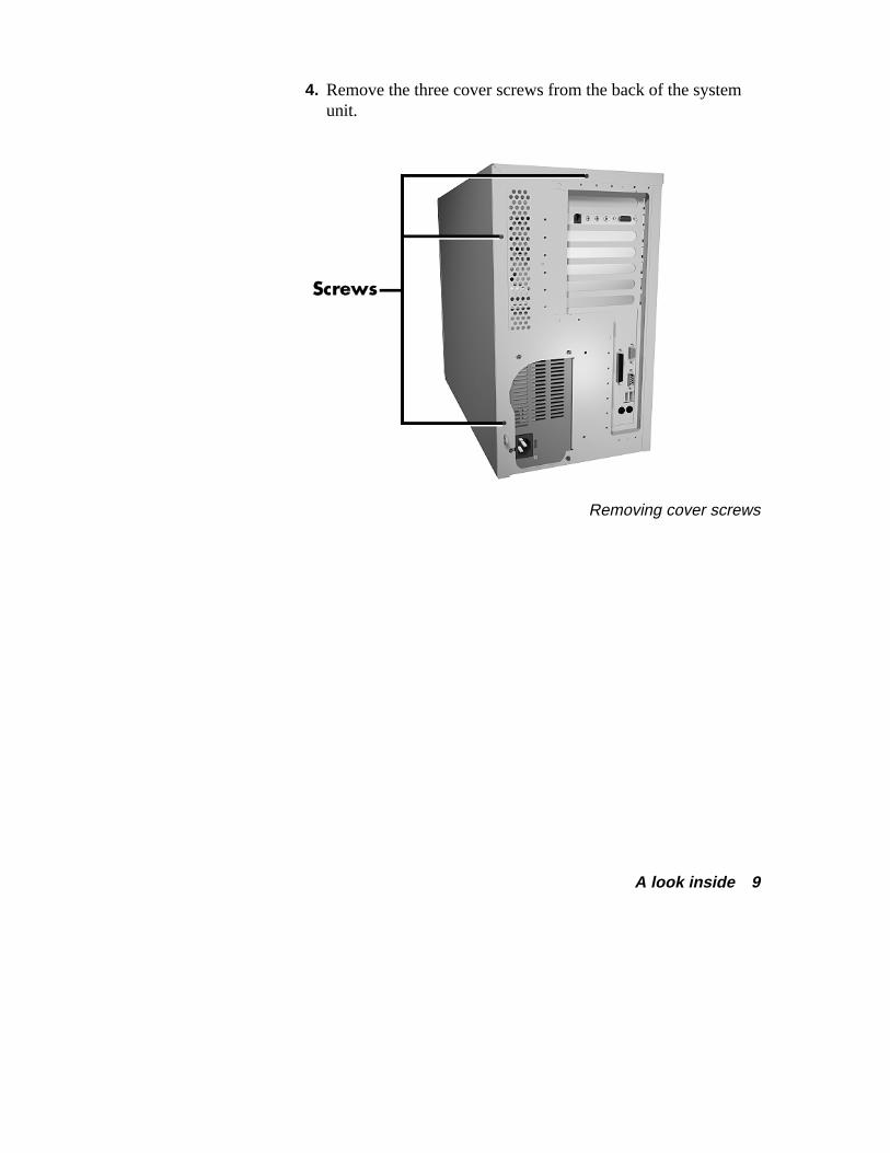
4. Remove the three cover screws from the back of the systemunit.
Removing cover screws
10 A look inside
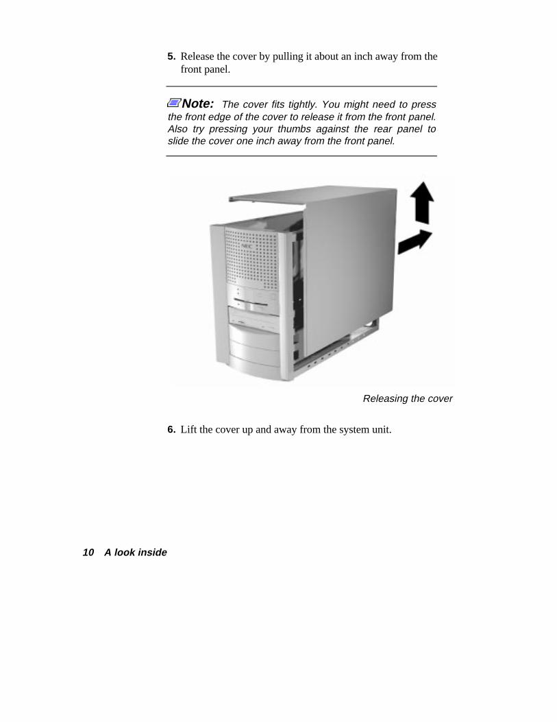
5. Release the cover by pulling it about an inch away from thefront panel.
Note: The cover fits tightly. You might need to pressthe front edge of the cover to release it from the front panel.Also try pressing your thumbs against the rear panel toslide the cover one inch away from the front panel.
Releasing the cover
6. Lift the cover up and away from the system unit.
A look inside 11
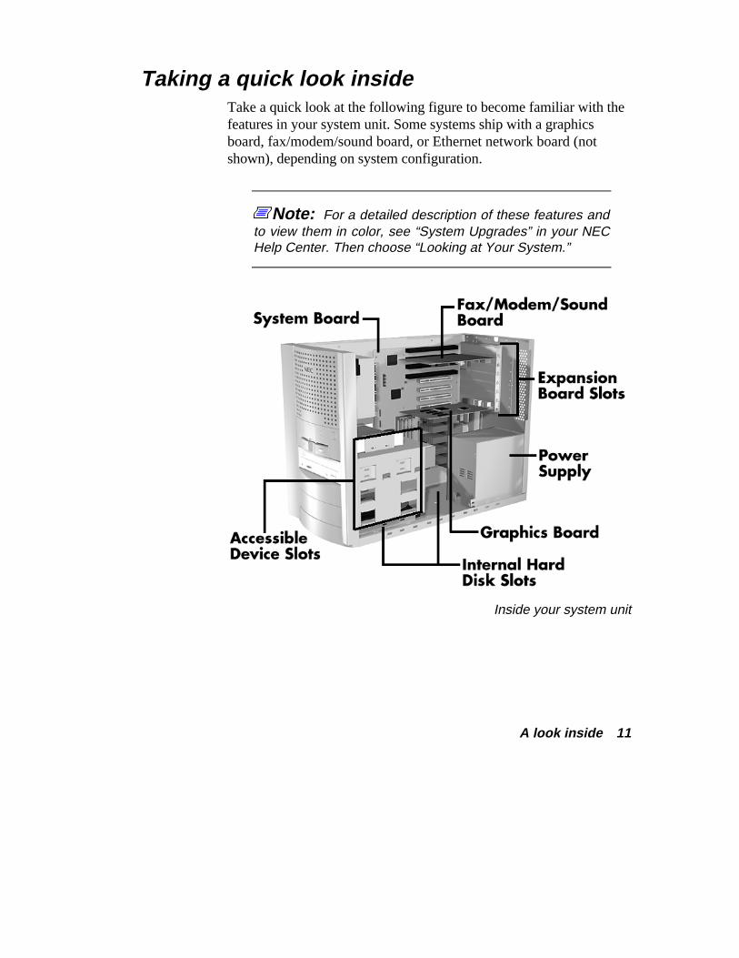
Taking a quick look inside Take a quick look at the following figure to become familiar with thefeatures in your system unit. Some systems ship with a graphicsboard, fax/modem/sound board, or Ethernet network board (notshown), depending on system configuration.
Note: For a detailed description of these features andto view them in color, see “System Upgrades” in your NECHelp Center. Then choose “Looking at Your System.”
Inside your system unit
12 A look inside
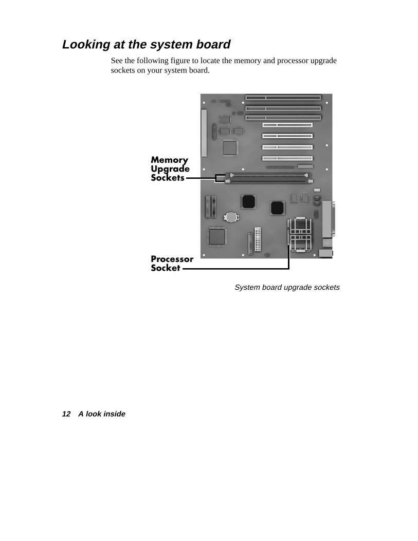
Looking at the system board See the following figure to locate the memory and processor upgradesockets on your system board.
System board upgrade sockets
A look inside 13
Replacing the cover Use the following steps to replace the system unit cover.
! CAUTION To prevent damage to the system cables, carefully tuck thecables out of the path of the cover.
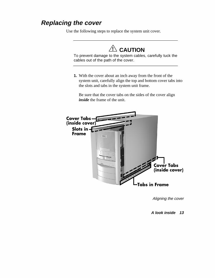
1. With the cover about an inch away from the front of thesystem unit, carefully align the top and bottom cover tabs intothe slots and tabs in the system unit frame.
Be sure that the cover tabs on the sides of the cover aligninside the frame of the unit.
Aligning the cover

14 A look inside
2. Slide the cover forward to meet the front panel.
Note: The cover fits tightly. If the cover does not slideall the way to the front panel, place one hand on the frontof the unit while you slide the cover forward from the rear.
3. Secure the cover with the three cover screws removed earlier(see “Taking off the cover”).
4. If you have a cover lock, replace it and secure it.
5. Connect the monitor, keyboard, mouse, and any other externaldevices to the back of the system unit.
6. Plug in your power cables.

System memory 15
System memory See the following sections for information about:
� the memory upgrade kits for your computer
� how to identify the memory in your system
� where to install additional memory
� how to add memory.
16 System memory
Looking at memory upgrade kits Memory upgrade kits are installed in two memory upgrade sockets onthe system board. Your system board ships with 32 MB of high-speedmemory and supports up to 128 MB of memory.
Note: Memory upgrade kits for your computer containmodules referred to in the computer industry as “dual in-linememory modules” or “DIMM” sticks.
Your system supports the following 60-ns 64-bit (non-parity)synchronous dynamic random access memory (SDRAM)configurations:
� 1-MB by 64-bit DIMM stick (4-MB module)
� 2-MB by 64-bit DIMM stick (8-MB module)
� 4-MB by 64-bit DIMM stick (16-MB module)
� 8-MB by 64-bit DIMM stick (32-MB module)
� 16-MB by 64-bit DIMM stick (64-MB module).
! CAUTION To avoid corrosion between different metals, only usememory modules with gold-plated connectors.
System memory 17
Checking the memory in your system Use the following procedure to:
� check the memory installed in your system
� determine the memory configuration you need to increaseyour memory
� identify the correct sockets for the memory upgrade.
1. If you don’t know how much memory is installed in yoursystem, you can check the amount in Windows® 95. On theWindows 95 desktop, point to My Computer and click theright mouse button.
With the left mouse button, click Properties. The General tabshows the random access memory (RAM). This is the amountof system memory in your computer.
You can also find the amount of memory by selecting thePerformance tab.
2. Remove the system unit cover (see “Taking off the cover”).
! WARNING Be sure that the system unit power is turned off and thesystem is unplugged before you begin the installationprocedure.
18 System memory
3. Determine the amount of memory you want to add and themodules you need. Modules do not need to be added in pairs.You may add modules singly.
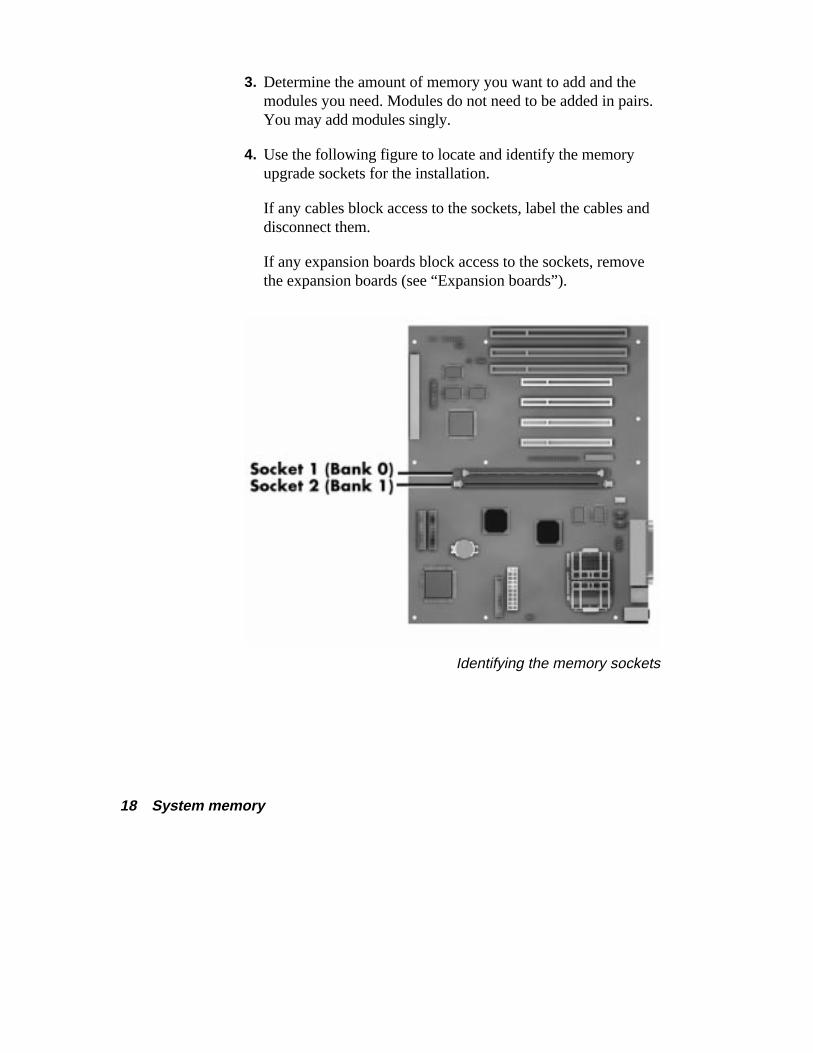
4. Use the following figure to locate and identify the memoryupgrade sockets for the installation.
If any cables block access to the sockets, label the cables anddisconnect them.
If any expansion boards block access to the sockets, removethe expansion boards (see “Expansion boards”).
Identifying the memory sockets
System memory 19
Adding memory modules Use the following steps to install memory modules.
1. Remove the system unit cover (see “Taking off the cover”).
! WARNING Be sure that the system unit power is turned off and thesystem is unplugged before you begin the installationprocedure.
2. Locate the memory upgrade sockets for your configuration(see “Checking the memory in your system”).
If you need to remove a memory module, see “Removing amemory module” in this guide.
! CAUTION Before you install a memory module, reduce staticdischarge by touching the system’s metal chassis.
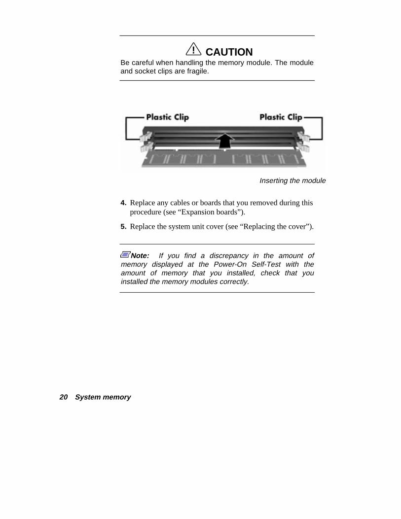
3. Insert the memory module as follows:
� Press out the plastic locking clips at the ends of an emptysocket.
� Align the notches on the module with the keys in thememory socket.
� Insert the module into the socket.
� Press in the plastic locking clips at the ends of the socketuntil they lock in place on the module.
20 System memory
! CAUTION Be careful when handling the memory module. The moduleand socket clips are fragile.
Inserting the module
4. Replace any cables or boards that you removed during thisprocedure (see “Expansion boards”).
5. Replace the system unit cover (see “Replacing the cover”).
Note: If you find a discrepancy in the amount ofmemory displayed at the Power-On Self-Test with theamount of memory that you installed, check that youinstalled the memory modules correctly.
System memory 21
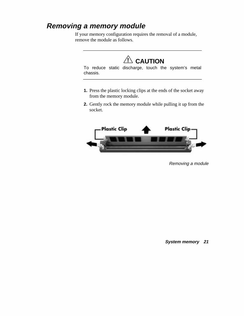
Removing a memory module If your memory configuration requires the removal of a module,remove the module as follows.
! CAUTION To reduce static discharge, touch the system’s metalchassis.
1. Press the plastic locking clips at the ends of the socket awayfrom the memory module.
2. Gently rock the memory module while pulling it up from thesocket.
Removing a module

Expansion boards 23
Expansion boards You’ll find information in the following sections about:
� how to add a board to your computer
� how to remove a board from your computer.
Note: See the board removal procedure when a boardis in the way of adding other options or connecting cables.
24 Expansion boards
Adding boards Use the following steps to add a board to your system unit.
! WARNING Be sure that the system unit power is turned off and thesystem is unplugged before you begin the installationprocedure.
1. Follow any preinstallation instructions that come with yourexpansion board (such as setting switches or jumpers on theboard).
2. See the information that comes with your board to determinewhich type of board you have:
� an 8-bit or 16-bit Industry Standard Architecture (ISA)board
� a 32-bit Peripheral Component Interconnect (PCI)board.
3. Remove the system unit cover (see “Taking off the cover”).
Expansion boards 25
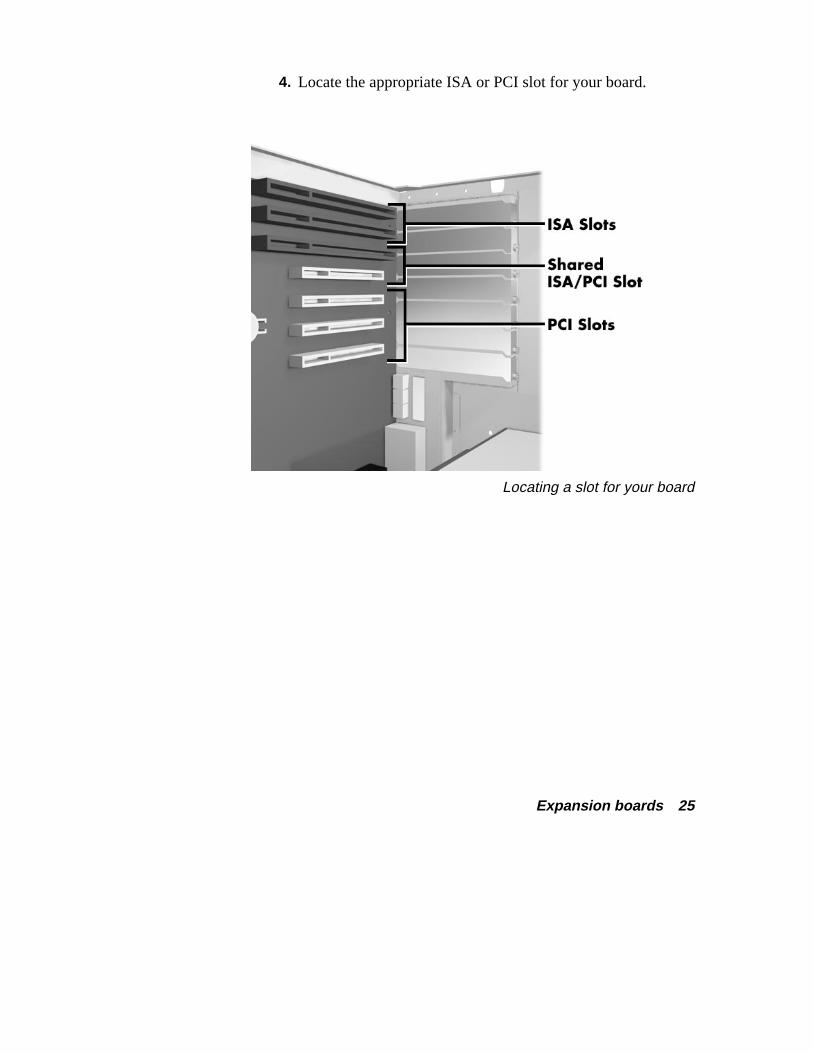
4. Locate the appropriate ISA or PCI slot for your board.
Locating a slot for your board
26 Expansion boards
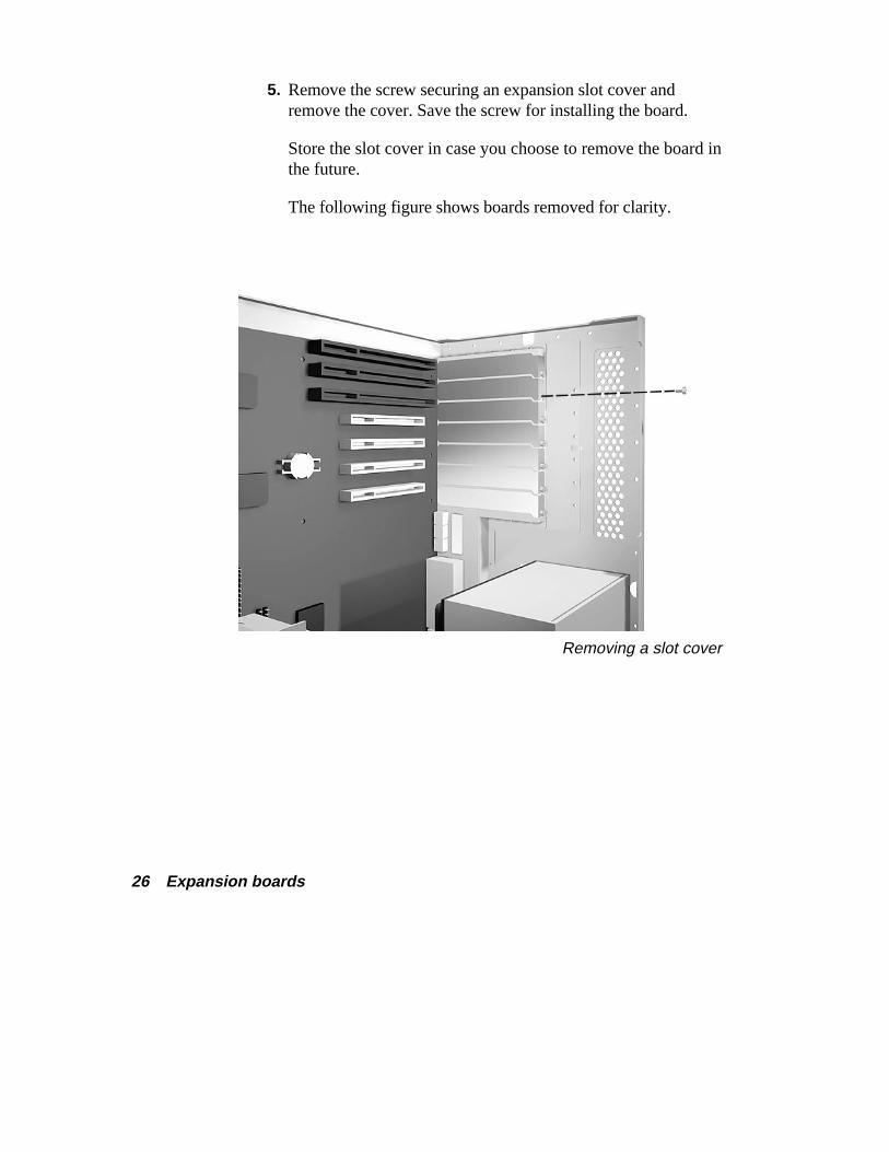
5. Remove the screw securing an expansion slot cover andremove the cover. Save the screw for installing the board.
Store the slot cover in case you choose to remove the board inthe future.
The following figure shows boards removed for clarity.
Removing a slot cover
Expansion boards 27
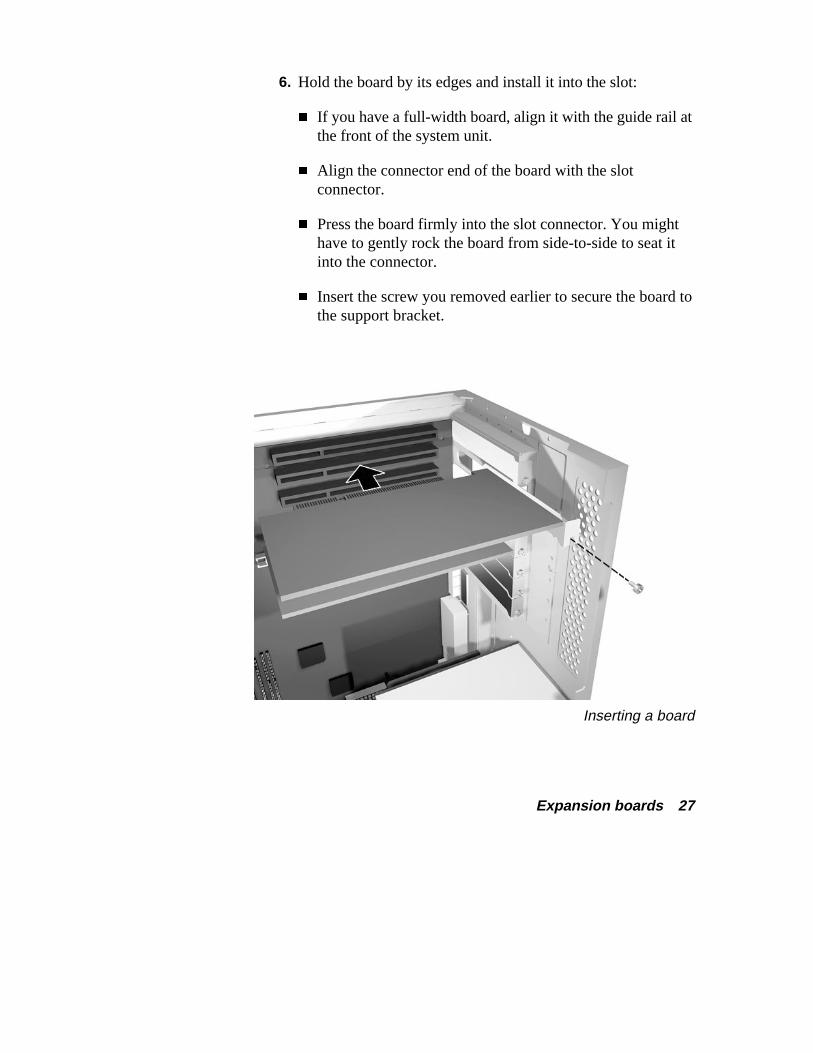
6. Hold the board by its edges and install it into the slot:
� If you have a full-width board, align it with the guide rail atthe front of the system unit.
� Align the connector end of the board with the slotconnector.
� Press the board firmly into the slot connector. You mighthave to gently rock the board from side-to-side to seat itinto the connector.
� Insert the screw you removed earlier to secure the board tothe support bracket.
Inserting a board
28 Expansion boards
7. Replace the system unit cover (see “Replacing the cover”).
8. Add any necessary drivers. See the instructions that comewith the board for information about driver requirements.
Removing a board See the following steps to remove a board from your system unit.
! WARNING Be sure that the system unit power is turned off and thesystem is unplugged before you begin the removalprocedure.
1. Remove the system unit cover (see “Taking off the cover”).
2. If you have any cables connected to the board that you needto remove, label the cable.
On the label, write or draw the following cable information:
� Location of the connector on the board.
� Note the cable connector alignment. Look for a colorededge of the cable and notice whether it is on the right, left,top, or bottom side of the board connector.
Then disconnect the cable from the board.
Expansion boards 29
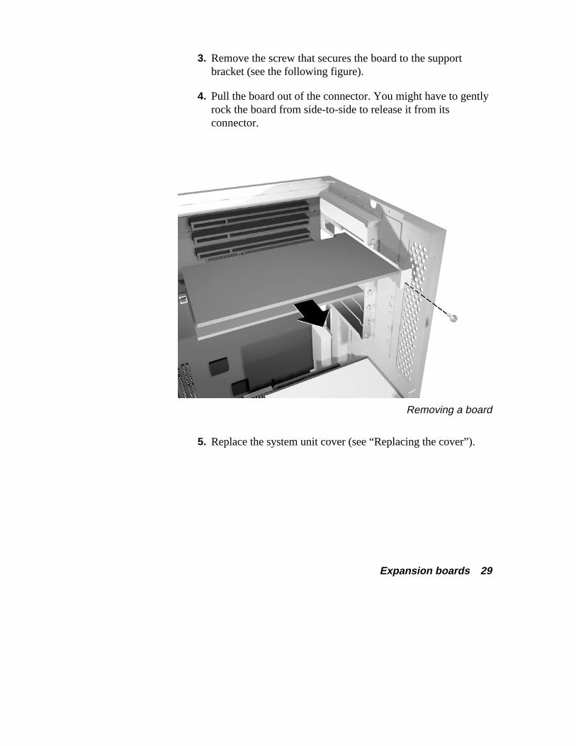
3. Remove the screw that secures the board to the supportbracket (see the following figure).
4. Pull the board out of the connector. You might have to gentlyrock the board from side-to-side to release it from itsconnector.
Removing a board
5. Replace the system unit cover (see “Replacing the cover”).
System processor 31
System processor See the following sections for information about:
� removing the processor in your computer
� adding an upgrade processor, such as an Intel®
OverDrive™ processor.
32 System processor
Removing the processor To upgrade your processor, you must first remove the processorcurrently in your computer. Use the following steps to remove it.
1. Remove the system unit cover (see “Taking off the cover”).
! WARNING Be sure that the system unit power is turned off and thesystem is unplugged before you begin the installationprocedure.
2. Locate the processor socket on the system board (see“Looking at the system board”).
If you have expansion boards obstructing your view of thesocket, remove them (see “Removing a board”).
If the power supply is obstructing your access to theprocessor socket, remove it (see step 3). Check “Taking aquick look inside” for the location of the power supply.
System processor 33
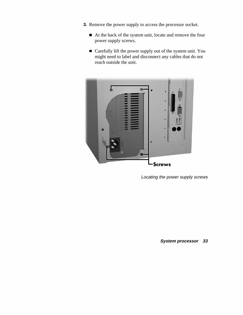
3. Remove the power supply to access the processor socket.
� At the back of the system unit, locate and remove the fourpower supply screws.
� Carefully lift the power supply out of the system unit. Youmight need to label and disconnect any cables that do notreach outside the unit.
Locating the power supply screws

34 System processor
4. Release the heatsink clamp from the socket tabs.
Releasing the heatsink clamp
5. Release the processor by pulling the socket lever away fromthe socket and as far back as it can go without forcing.
! CAUTION Before you pick up the processor, reduce static dischargeby touching the metal frame of the chassis.
6. Lift the processor out of the socket.
System processor 35
Adding a processor Use the following steps to add a processor upgrade to your computer.
1. Remove the processor currently in your system (see“Removing the processor”).
! CAUTION Before you pick up the processor, reduce static dischargeby touching the metal frame of the chassis.
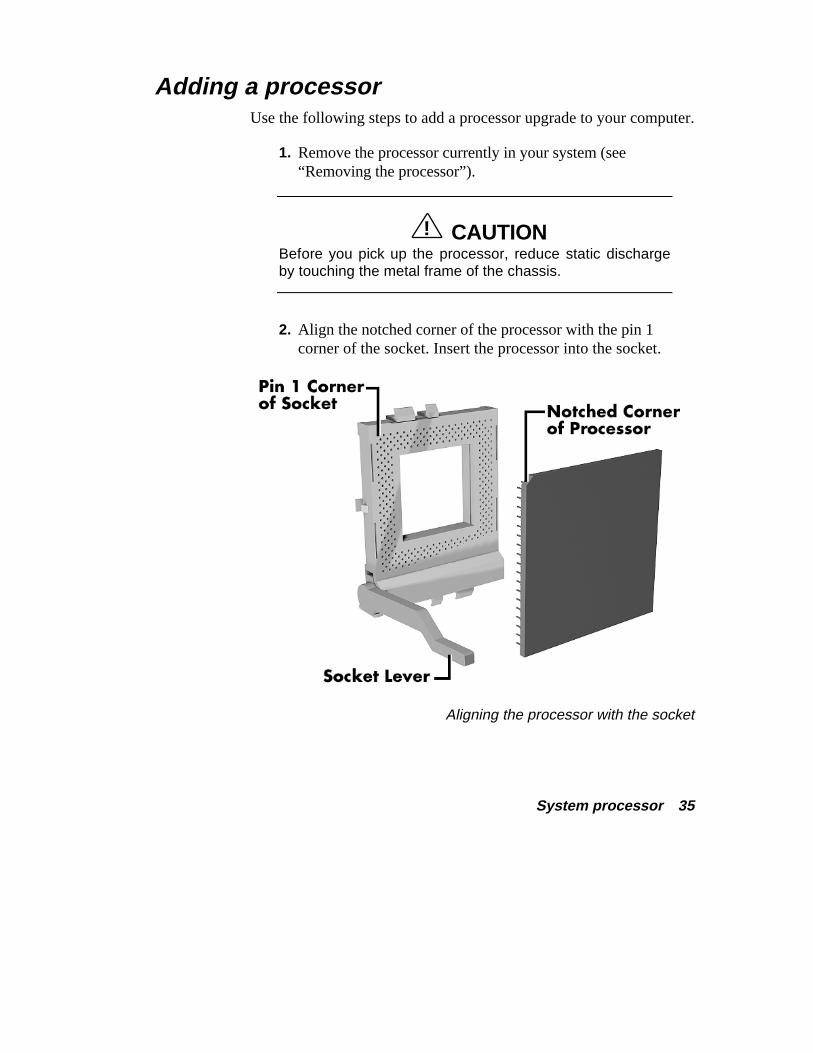
2. Align the notched corner of the processor with the pin 1corner of the socket. Insert the processor into the socket.
Aligning the processor with the socket
36 System processor
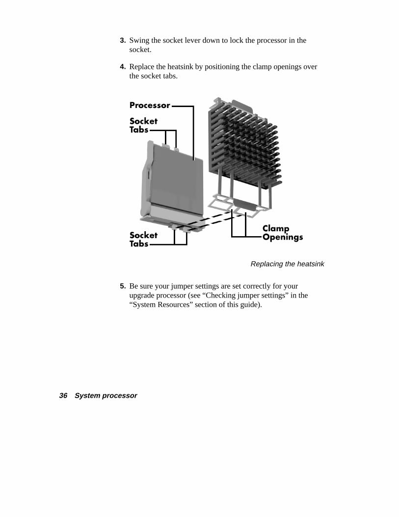
3. Swing the socket lever down to lock the processor in thesocket.
4. Replace the heatsink by positioning the clamp openings overthe socket tabs.
Replacing the heatsink
5. Be sure your jumper settings are set correctly for yourupgrade processor (see “Checking jumper settings” in the“System Resources” section of this guide).
System processor 37
6. Replace the power supply you removed during this procedure.
� If you disconnected any cables from the power supply,reconnect them.
� Secure the power supply with the four screws you removedearlier.
7. Replace any expansion boards you might have removed duringthis procedure (see “Adding a board”).
8. Replace the system unit cover (see “Replacing the cover”).
Storage devices 39
Storage devices Your Ready computer holds up to six storage devices. For adescription of which devices you have and what you can add, go toyour online NEC Help Center and select “System Upgrades.” Select“Adding Upgrade Options” and choose “Data Storage Devices.”
If you’re ready to add an option, see the following sections:
� preparing your device for installation
� identifying the cables you need
� connecting the cables to your device
� installing storage devices.
40 Storage devices
Preparing the device Before you install a storage device in your computer, follow anypreinstallation instructions that come with the device.
For example:
� Diskette drive — remove any termination on an optionaldiskette drive. See the documentation that comes with thedrive.
� IDE device — check the jumper settings on an IDE devicebefore you install it. See the documentation that comes withthe device for jumper setting information.
If you have an IDE device, you need to know which of the two IDEconnectors, primary or secondary, you are going to use to add yourdevice. Here’s some information about the IDE connection:
� An IDE device, such as an IDE hard disk or IDE CD-ROMreader, must be set correctly as the first (master) or second(slave) device on the primary or secondary IDE connector onthe system board.
� One master device and one slave device are supported on theprimary IDE connector, and one master and one slave deviceare supported on the secondary IDE connector.
The IDE hard disk that comes with your system is set as the masterdevice on the high-speed primary IDE connector. The CD-ROMreader that comes with your system is set as the master device on thesecondary IDE connector. Any optional IDE device that you installmust be set as the slave device on the primary or secondary IDEconnector.
See “IDE cables” in the next section for more information about IDEconnections.
Storage devices 41
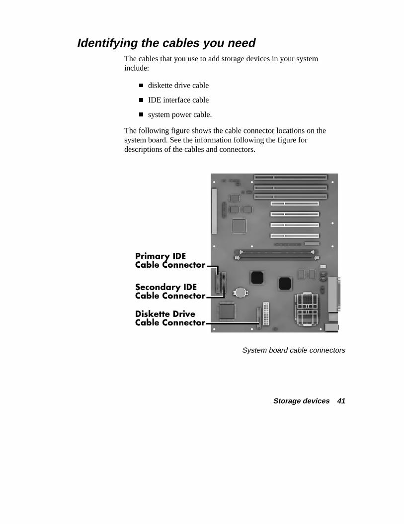
Identifying the cables you need The cables that you use to add storage devices in your systeminclude:
� diskette drive cable
� IDE interface cable
� system power cable.
The following figure shows the cable connector locations on thesystem board. See the information following the figure fordescriptions of the cables and connectors.
System board cable connectors
42 Storage devices
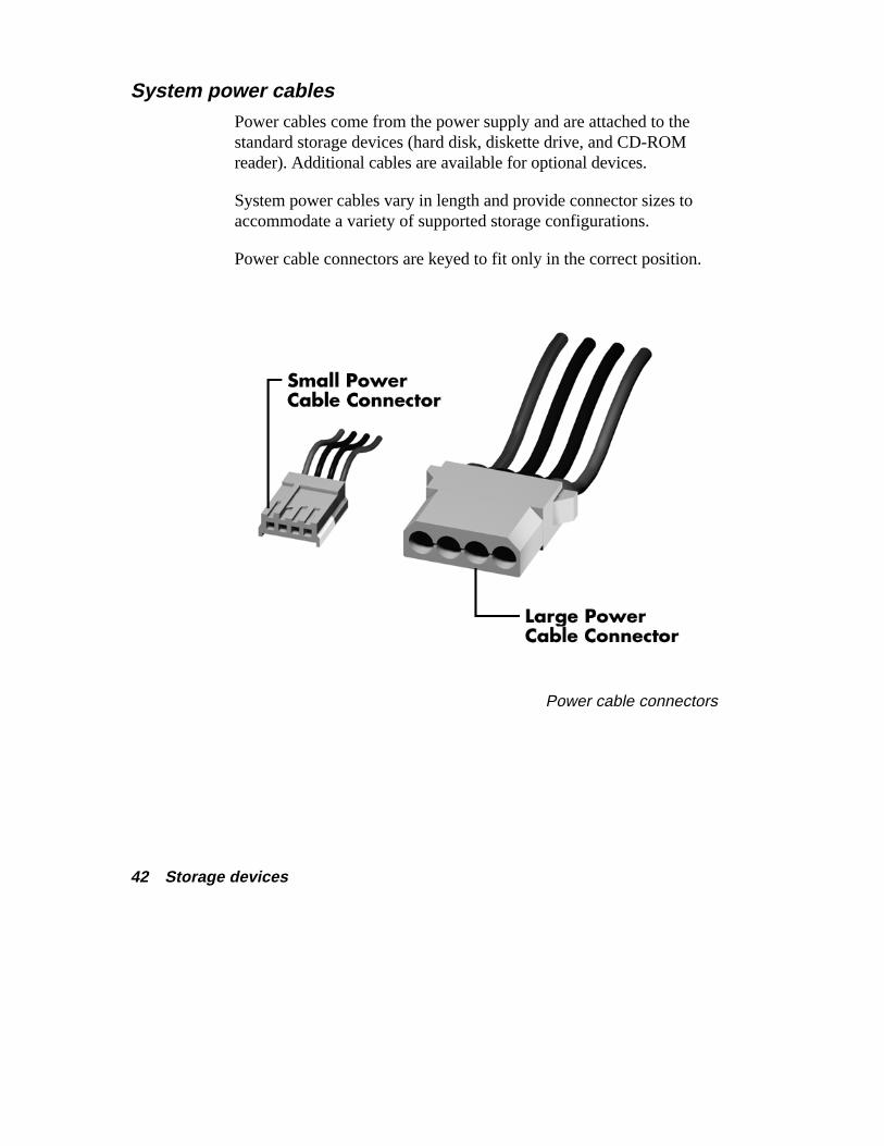
System power cables Power cables come from the power supply and are attached to thestandard storage devices (hard disk, diskette drive, and CD-ROMreader). Additional cables are available for optional devices.
System power cables vary in length and provide connector sizes toaccommodate a variety of supported storage configurations.
Power cable connectors are keyed to fit only in the correct position.
Power cable connectors
Storage devices 43
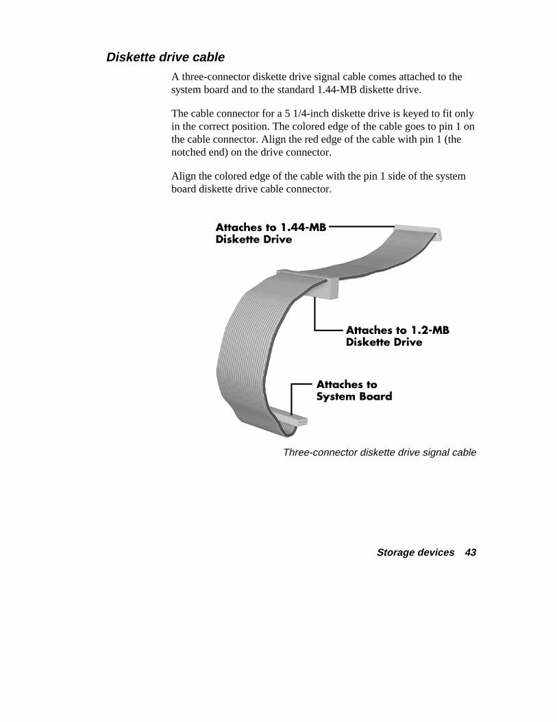
Diskette drive cable A three-connector diskette drive signal cable comes attached to thesystem board and to the standard 1.44-MB diskette drive.
The cable connector for a 5 1/4-inch diskette drive is keyed to fit onlyin the correct position. The colored edge of the cable goes to pin 1 onthe cable connector. Align the red edge of the cable with pin 1 (thenotched end) on the drive connector.
Align the colored edge of the cable with the pin 1 side of the systemboard diskette drive cable connector.
Three-connector diskette drive signal cable
44 Storage devices
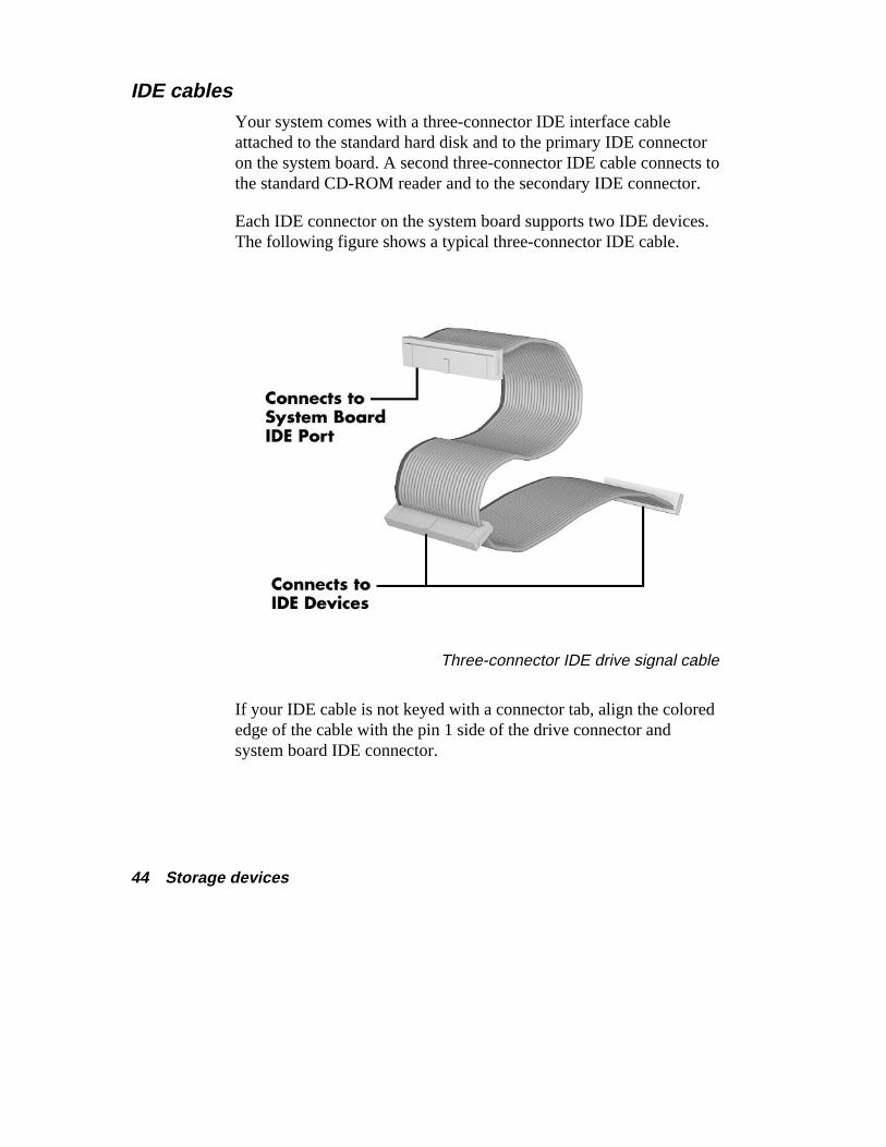
IDE cables Your system comes with a three-connector IDE interface cableattached to the standard hard disk and to the primary IDE connectoron the system board. A second three-connector IDE cable connects tothe standard CD-ROM reader and to the secondary IDE connector.
Each IDE connector on the system board supports two IDE devices.The following figure shows a typical three-connector IDE cable.
Three-connector IDE drive signal cable
If your IDE cable is not keyed with a connector tab, align the colorededge of the cable with the pin 1 side of the drive connector andsystem board IDE connector.
Storage devices 45
Connecting cables to your device All storage devices require a power cable and a signal cableconnection. The devices that come with your system are alreadyconnected.
Use the information in the following section along with theappropriate procedure in “Installing storage devices” to installoptional devices. Refer to the appropriate section to cable yourdevice:
� “Cabling an IDE device”
� “Cabling a diskette drive.”
Cabling an IDE device Use the following steps to cable an IDE device such as an IDE harddisk or CD-ROM reader.
1. Connect the unused connector on the installed IDE cable (see“IDE cable”) to the IDE device.
Take care to prevent bending drive connector pins. Align theIDE cable connector as shown in the following figure.
46 Storage devices
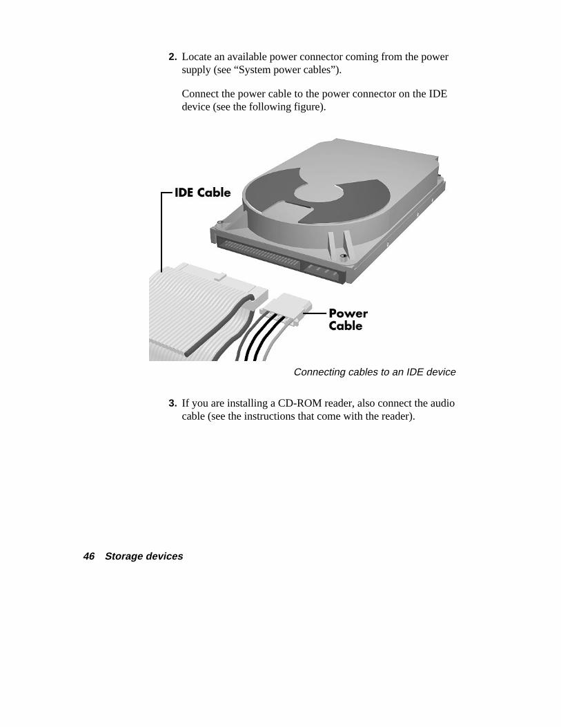
2. Locate an available power connector coming from the powersupply (see “System power cables”).
Connect the power cable to the power connector on the IDEdevice (see the following figure).
Connecting cables to an IDE device
3. If you are installing a CD-ROM reader, also connect the audiocable (see the instructions that come with the reader).
Storage devices 47
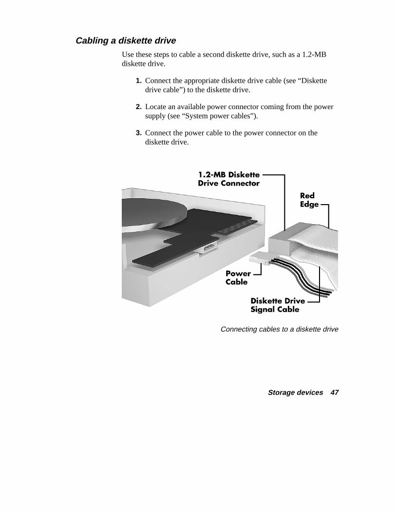
Cabling a diskette drive Use these steps to cable a second diskette drive, such as a 1.2-MBdiskette drive.
1. Connect the appropriate diskette drive cable (see “Diskettedrive cable”) to the diskette drive.
2. Locate an available power connector coming from the powersupply (see “System power cables”).
3. Connect the power cable to the power connector on thediskette drive.
Connecting cables to a diskette drive
48 Storage devices
Installing storage devices Your Ready computer comes with one free 3 1/2-inch device slot andtwo free 5 1/4-inch device slots. See the following procedures to addyour storage device:
� “Adding a 3 1/2-inch hard disk”
� “Adding a 5 1/4-inch device.”
Adding a 3 1/2-inch hard disk Use the following steps to add a 3 1/2-inch hard disk to your system.
1. Follow the preinstallation instructions that come with yourdevice, such as setting jumpers and switches.
See “Preparing your device” earlier in this guide forpreparation information.
Be sure you have handy the four screws that come with thehard disk.
2. Remove the system unit cover (see “Taking off the cover”).
! WARNINGBe sure that the system power is off and the system and itsperipherals are unplugged before you begin theinstallation procedure.
Storage devices 49
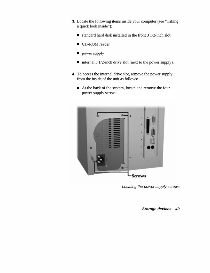
3. Locate the following items inside your computer (see “Takinga quick look inside”):
� standard hard disk installed in the front 3 1/2-inch slot
� CD-ROM reader
� power supply
� internal 3 1/2-inch drive slot (next to the power supply).
4. To access the internal drive slot, remove the power supplyfrom the inside of the unit as follows:
� At the back of the system, locate and remove the fourpower supply screws.
Locating the power supply screws

50 Storage devices
� Carefully lift the power supply out of the system unit. Youmight need to label and disconnect any cables that do notreach outside the unit.
5. Connect the IDE and power cables to the new hard disk asfollows:
� Carefully place the system unit on its side with the openside facing up.
� Locate the four holes on the bottom of the hard disk.
� Hold the hard disk with the holes facing the floor of thesystem unit and the connectors facing the front of the unit.
� Connect the IDE and power cables to the hard disk (see“IDE cables”).
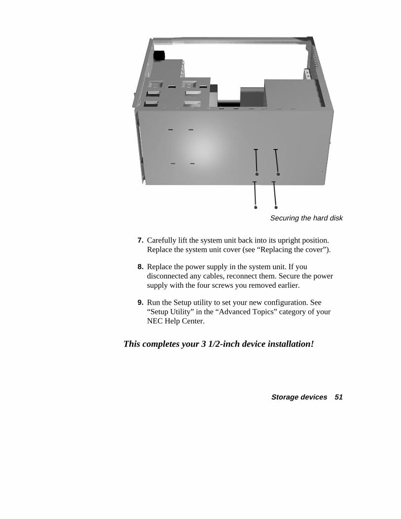
6. Install the hard disk in the drive slot as follows:
� Locate the four holes on the bottom of the system unit (seethe following figure).
� Position the hard disk in the hard disk drive slot area (see“Taking a quick look inside”).
� Align the four holes on the bottom of the hard disk withthe holes in the drive slot (see the following figure).
Secure the hard disk with the four screws that come withthe hard disk.
Storage devices 51
Securing the hard disk
7. Carefully lift the system unit back into its upright position.Replace the system unit cover (see “Replacing the cover”).
8. Replace the power supply in the system unit. If youdisconnected any cables, reconnect them. Secure the powersupply with the four screws you removed earlier.
9. Run the Setup utility to set your new configuration. See“Setup Utility” in the “Advanced Topics” category of yourNEC Help Center.
This completes your 3 1/2-inch device installation!
52 Storage devices
Adding a 5 1/4-inch device Use the following steps to add a 5 1/4-inch device into an accessibledevice slot in your system.
1. Follow the preinstallation instructions that come with yourdevice, such as setting jumpers and switches.
See “Preparing your device” earlier in this guide forpreparation information.
Note: If your 5 1/4-inch device comes with drive rails,do not attach them. Remove any rails already attached.See the documentation that comes with the device.
2. Remove the system unit cover (see “Taking off the cover”).
! WARNINGBe sure that the system power is off and the system and itsperipherals are unplugged before you begin theinstallation procedure.
3. Remove the front panel by carefully pulling it off the front ofthe system unit. Use an even amount of pressure around theedges of the panel.
Note: The front panel is secured with six lockingplugs.
Storage devices 53
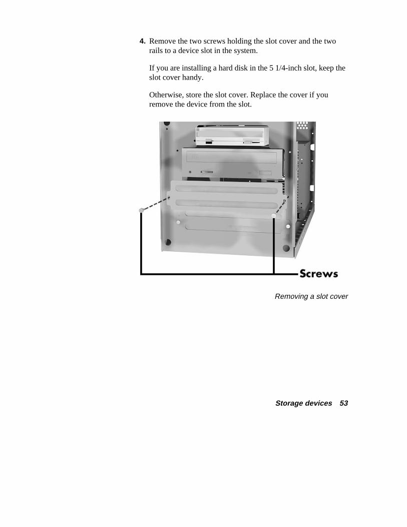
4. Remove the two screws holding the slot cover and the tworails to a device slot in the system.
If you are installing a hard disk in the 5 1/4-inch slot, keep theslot cover handy.
Otherwise, store the slot cover. Replace the cover if youremove the device from the slot.
Removing a slot cover
54 Storage devices
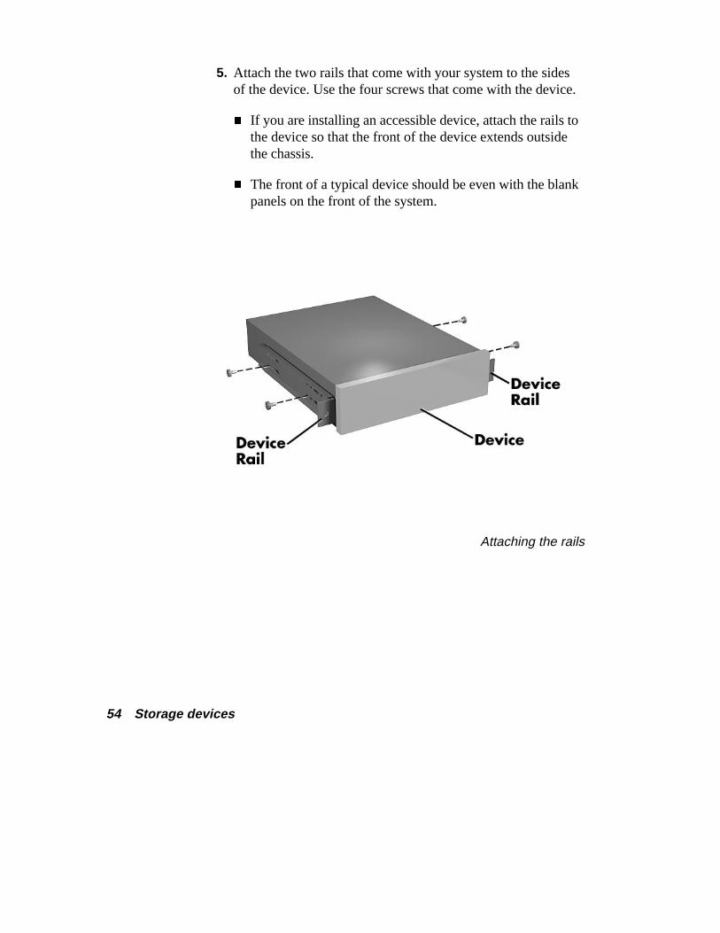
5. Attach the two rails that come with your system to the sidesof the device. Use the four screws that come with the device.
� If you are installing an accessible device, attach the rails tothe device so that the front of the device extends outsidethe chassis.
� The front of a typical device should be even with the blankpanels on the front of the system.
Attaching the rails
Storage devices 55
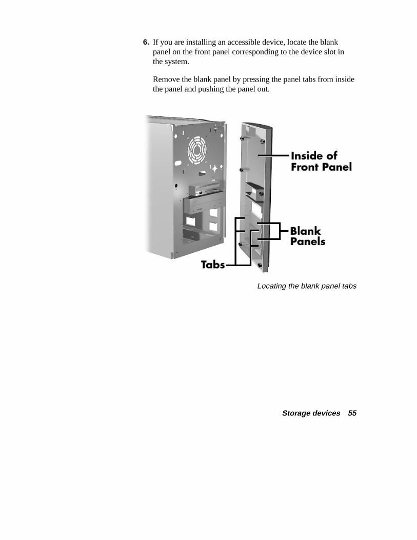
6. If you are installing an accessible device, locate the blankpanel on the front panel corresponding to the device slot inthe system.
Remove the blank panel by pressing the panel tabs from insidethe panel and pushing the panel out.
Locating the blank panel tabs
56 Storage devices
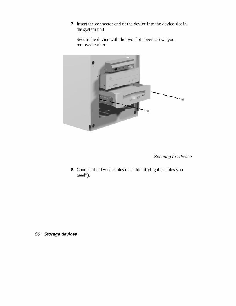
7. Insert the connector end of the device into the device slot inthe system unit.
Secure the device with the two slot cover screws youremoved earlier.
Securing the device
8. Connect the device cables (see “Identifying the cables youneed”).
Storage devices 57
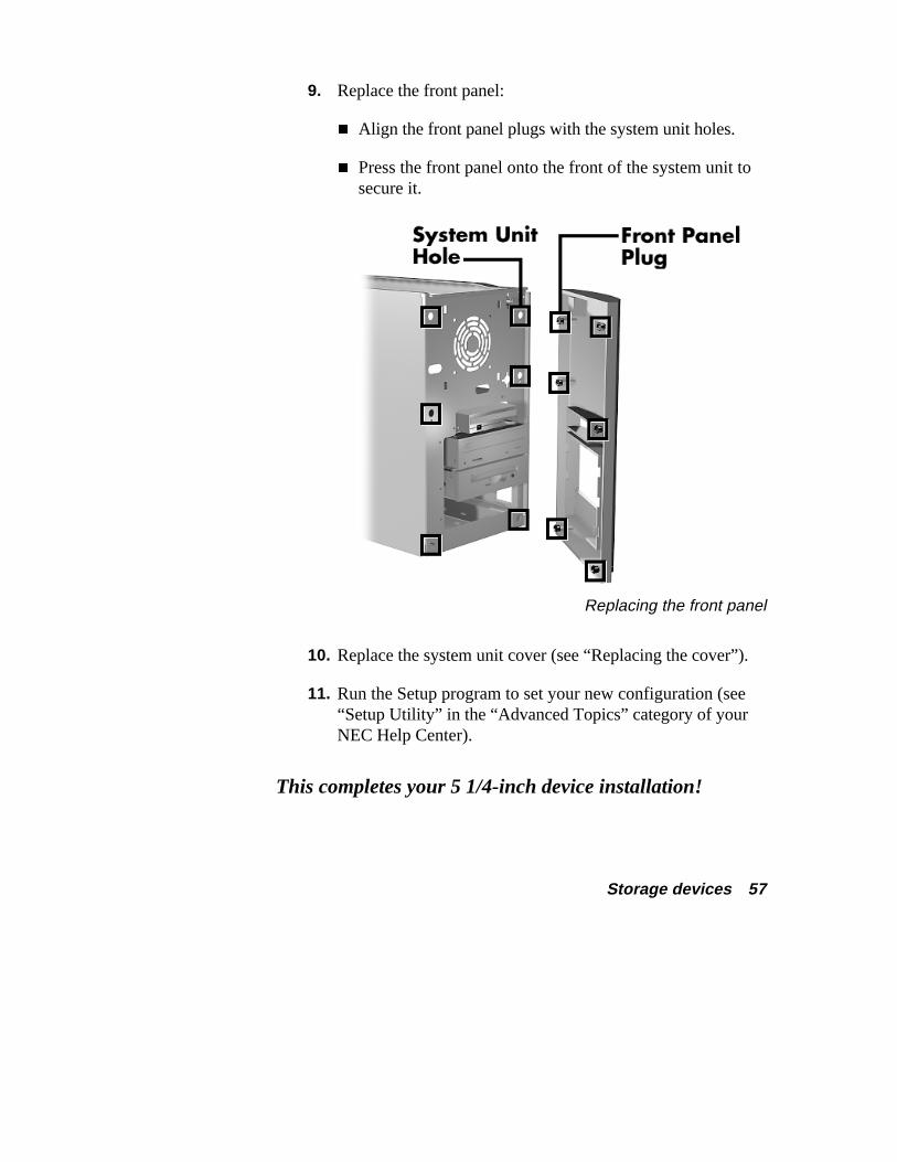
9. Replace the front panel:
� Align the front panel plugs with the system unit holes.
� Press the front panel onto the front of the system unit tosecure it.
Replacing the front panel
10. Replace the system unit cover (see “Replacing the cover”).
11. Run the Setup program to set your new configuration (see“Setup Utility” in the “Advanced Topics” category of yourNEC Help Center).
This completes your 5 1/4-inch device installation!
External options 59
External options The previous sections describe adding options to the inside of yourReady computer. You can also expand the capabilities of yourcomputer by adding options to the outside of the computer.
See the following sections to:
� locate the external connectors on your computer
� connect an NEC CS500™ monitor
� connect an NEC C700™ monitor
� connect a printer.
60 External options
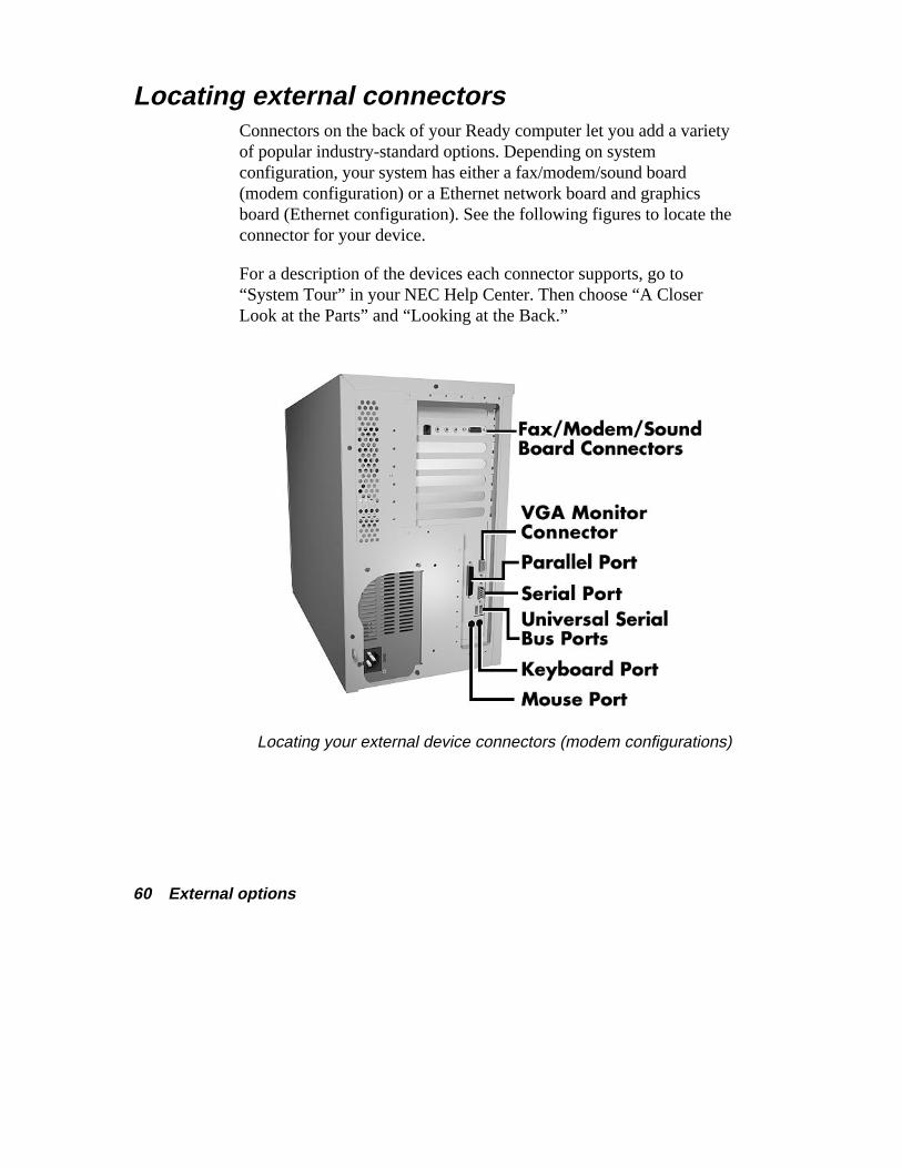
Locating external connectors Connectors on the back of your Ready computer let you add a varietyof popular industry-standard options. Depending on systemconfiguration, your system has either a fax/modem/sound board(modem configuration) or a Ethernet network board and graphicsboard (Ethernet configuration). See the following figures to locate theconnector for your device.
For a description of the devices each connector supports, go to“System Tour” in your NEC Help Center. Then choose “A CloserLook at the Parts” and “Looking at the Back.”
Locating your external device connectors (modem configurations)
External options 61
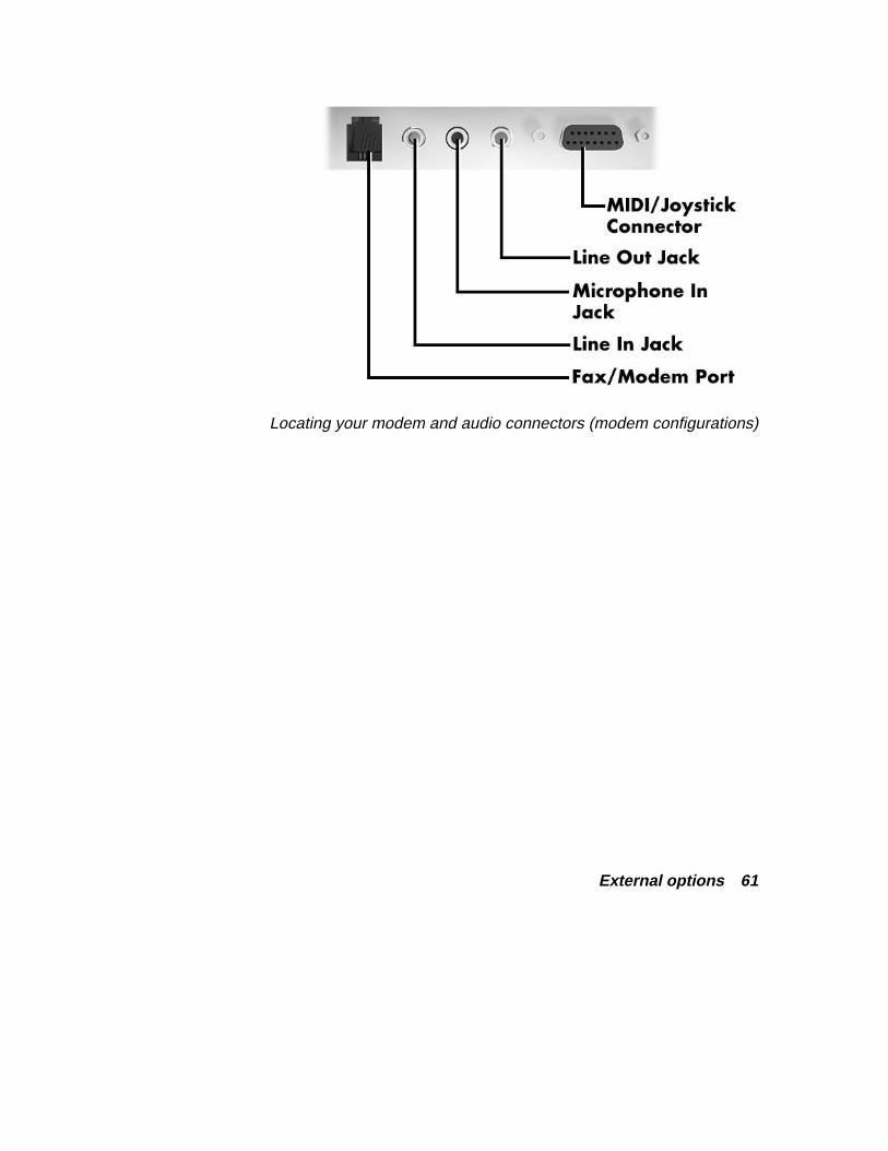
Locating your modem and audio connectors (modem configurations)
62 External options
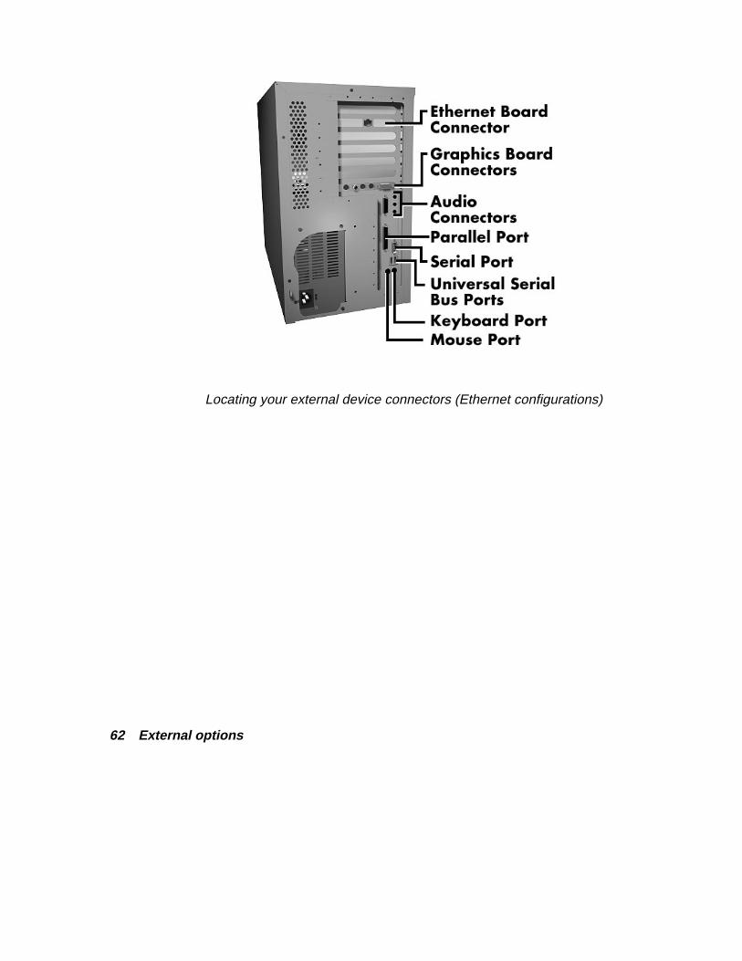
Locating your external device connectors (Ethernet configurations)
External options 63
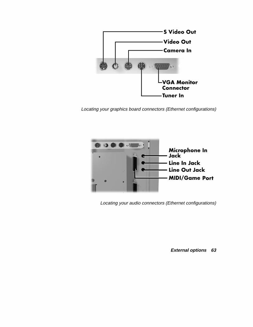
Locating your graphics board connectors (Ethernet configurations)
Locating your audio connectors (Ethernet configurations)
64 External options
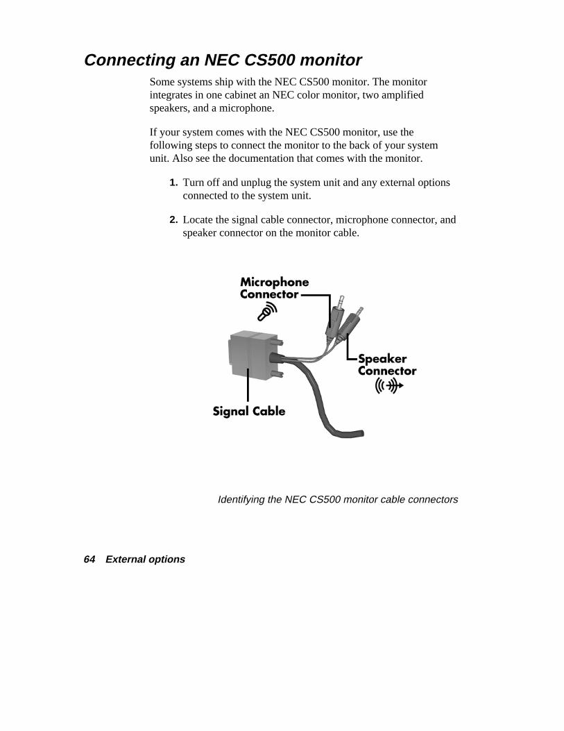
Connecting an NEC CS500 monitor Some systems ship with the NEC CS500 monitor. The monitorintegrates in one cabinet an NEC color monitor, two amplifiedspeakers, and a microphone.
If your system comes with the NEC CS500 monitor, use thefollowing steps to connect the monitor to the back of your systemunit. Also see the documentation that comes with the monitor.
1. Turn off and unplug the system unit and any external optionsconnected to the system unit.
2. Locate the signal cable connector, microphone connector, andspeaker connector on the monitor cable.
Identifying the NEC CS500 monitor cable connectors
External options 65
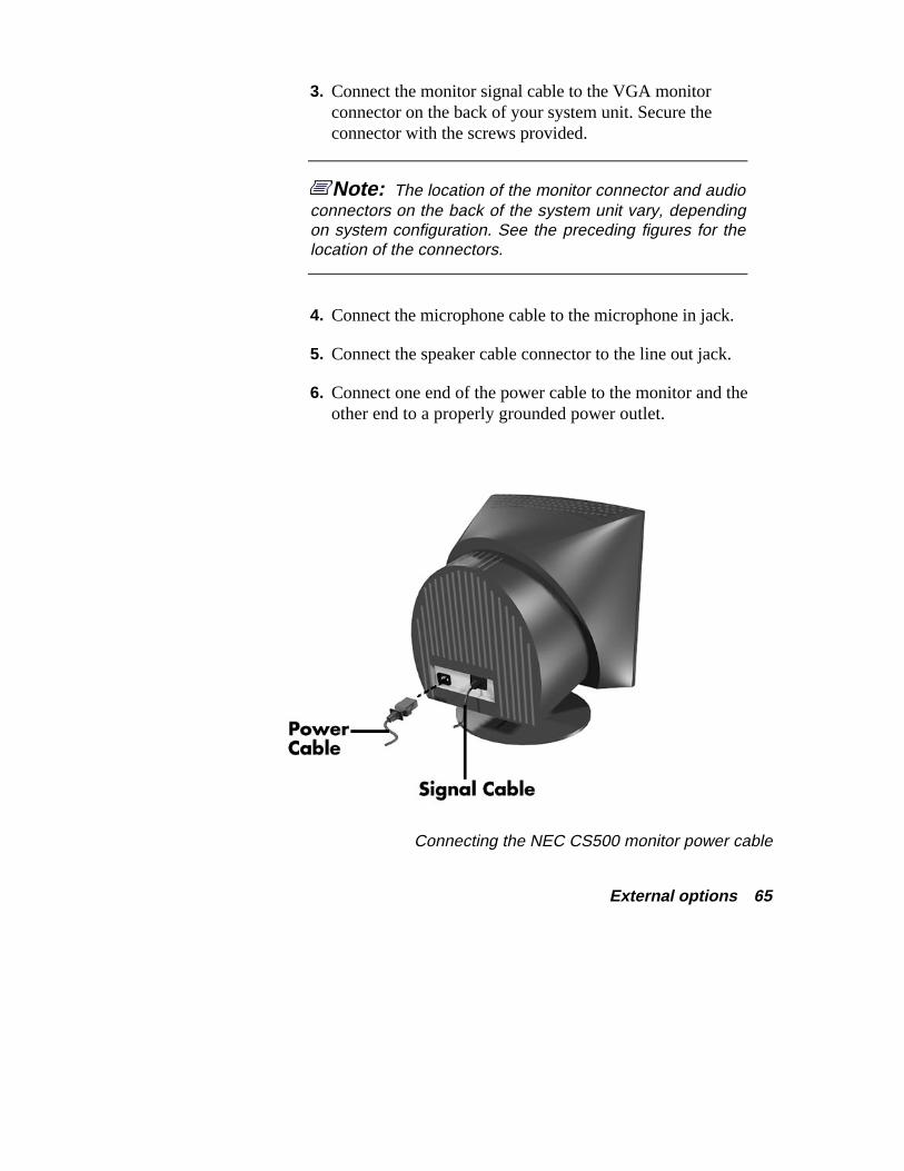
3. Connect the monitor signal cable to the VGA monitorconnector on the back of your system unit. Secure theconnector with the screws provided.
Note: The location of the monitor connector and audioconnectors on the back of the system unit vary, dependingon system configuration. See the preceding figures for thelocation of the connectors.
4. Connect the microphone cable to the microphone in jack.
5. Connect the speaker cable connector to the line out jack.
6. Connect one end of the power cable to the monitor and theother end to a properly grounded power outlet.
Connecting the NEC CS500 monitor power cable
66 External options
7. Reconnect the system unit power cable and any externaloption power cables to the system unit.
8. Press the power button on the front of the monitor.
9. Press the power button on the front of the system unit.
See the monitor’s documentation for further information on using themonitor with your system.
Connecting an NEC C700 monitor Some systems ship with an NEC C700 monitor, without speakers andmicrophone. You might want to add optional speakers and anoptional microphone.
Follow these general steps to connect the monitor and any optionalcomponents. Also see the documentation that comes with the unitsfor detailed connection information.
Note: The location of the monitor connector and audioconnectors on the back of the system unit vary, dependingon system configuration. See the preceding figures for thelocation of the connectors.
1. Turn off and unplug your system unit and any external optionsconnected to the system unit.
2. Connect the monitor signal cable to the VGA monitorconnector on the back of your system unit. Secure theconnector with the screws provided.
3. Connect the optional microphone to the microphone jack onthe back of your system unit.
External options 67
4. Connect the optional speaker set. See the documentation thatcomes with the speakers for additional connectioninformation.
� Connect the speakers.
� Connect the speaker-to-system cable to the line out jack onthe back of your system unit.
� If your speaker set has an AC adapter, connect the adapterto the speaker and to a grounded power source.
5. Connect the monitor power cable, system unit power cable,and any external option power cables to a grounded powersource.
See the monitor’s documentation for further information on using themonitor with your system.
68 External options
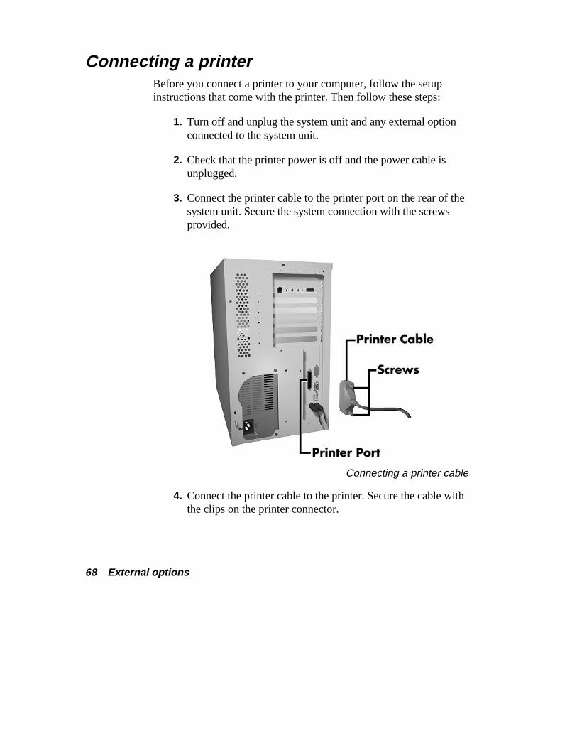
Connecting a printer Before you connect a printer to your computer, follow the setupinstructions that come with the printer. Then follow these steps:
1. Turn off and unplug the system unit and any external optionconnected to the system unit.
2. Check that the printer power is off and the power cable isunplugged.
3. Connect the printer cable to the printer port on the rear of thesystem unit. Secure the system connection with the screwsprovided.
Connecting a printer cable
4. Connect the printer cable to the printer. Secure the cable withthe clips on the printer connector.
External options 69
5. See the NEC Help Center for setting up a printer inWindows® 95.
If your printer is not included in the Windows 95 listing, see yourprinter manual or call the printer manufacturer.
System resources 71
System resources When you are setting up new hardware, your system might requireinformation such as available system resources. The followingsections include information about:
� system resources for your communications ports
� default system settings
� viewing system resources
� jumper settings on the system board.
72 System resources
Looking at communication ports Your system’s communications ports include a fax/modem port ornetwork port (depending on your system configuration) and a serialport.
Communication port settings are listed below.
� Fax/modem or network — enabled.
� Serial port 2 — enabled as serial port.
See the following sections for default system settings, interrupts, andinformation to view system resources.
Looking at COM port and IRQ settings The following settings are the default COM port and IRQ settings:
� Fax/modem or network — on COM1 (IRQ10)
� Serial port — on COM2 (IRQ3)
� COM B — enabled as serial port
� Windows 95 mode, MS-DOS mode, and MS-DOS box inWindows 95
IRQ0 (timer)
IRQ1 (keyboard)
IRQ2 (programmable interrupt controller)
IRQ3 COM2 (serial port)
IRQ4 (available)
IRQ5 (sound)
IRQ6 (floppy disk controller)
IRQ7 (LPT1)
System resources 73
IRQ8 (real time clock)
IRQ9 (MIDI device)
IRQ10 (modem/network)
IRQ11 (graphics/PCI handler)
IRQ12 (mouse)
IRQ13 (coprocessor)
IRQ14 (primary IDE)
IRQ15 (secondary IDE).
See the following section to view system resources.
Viewing system resources Some hardware option installations might require system resourcessuch as interrupt request (IRQ) lines, direct memory access (DMA)channels, and input/output (I/O) addresses. See the followingprocedures to view system resources.
Follow these steps to view system resources:
1. From the Windows 95 desktop, click the “My Computer” iconwith the right mouse button.
2. Click “Properties.” The System Properties box appears.
3. Click the Device Manager tab.
4. Double click “Computer.” The Computer Properties boxappears and displays the View Resources folder.
The View Resources folder shows the system resources used by yourcomputer. For example, it shows a list of interrupts and how they areallocated. If an interrupt is not in the list, it is available.
74 System resources
Checking jumper settings The following procedure explains how to locate and, if necessary,change jumper settings when you upgrade your processor. See thissection to also view factory jumper settings.
If a jumper change is required, lift the plastic block from the jumperpins with needle-nose pliers and place the block on the appropriatepins.
! CAUTION Jumpers are set correctly at the factory for your configuration.
If your system requires a jumper change, change only thesetting for that condition. Otherwise, keep the settings attheir factory settings.
! WARNING The system power must be off before changing a jumpersetting.
1. Power off and unplug the system and any attached devices.
2. Remove the system unit cover (see “Taking off the cover”earlier in this guide).
System resources 75
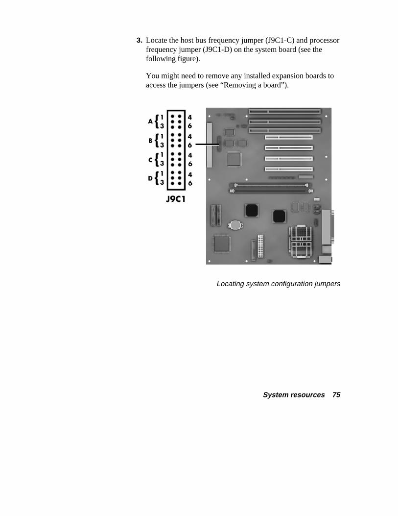
3. Locate the host bus frequency jumper (J9C1-C) and processorfrequency jumper (J9C1-D) on the system board (see thefollowing figure).
You might need to remove any installed expansion boards toaccess the jumpers (see “Removing a board”).
Locating system configuration jumpers

76 System resources
4. Check the processor and host bus frequency jumper settingson your system board using the following factory settings. Ifupgrading your processor, set the jumpers per the followingand the instructions included with the processor.
166-MHz processorHost PCI ISA Bus/Bus Bus Bus Processor
J9C1-C J9C1-D Freq. Freq. Freq. Freq. Ratio5-6 2-3, 5-6 66 MHz 33 MHz 8.33 MHz 2.5
200-MHz processorHost PCI ISA Bus/Bus Bus Bus Processor
J9C1-C J9C1-D Freq. Freq. Freq. Freq. Ratio5-6 1-2, 5-6 66 MHz 33 MHz 8.33 MHz 3
233-MHz processorHost PCI ISA Bus/Bus Bus Bus Processor
J9C1-C J9C1-D Freq. Freq. Freq. Freq. Ratio5-6 1-2, 4-5 66 MHz 33 MHz 8.33 MHz 3.5
5. Reinstall any removed expansion boards (see “Addingboards”).
6. Replace the system unit cover (see “Replacing the cover”).
7. Connect the system and monitor power cables and anyexternal options.
8. Power on the monitor and system.

System resources 77
Clearing your password If you forgot your password, use the following procedure to clearyour current password and to set a new one.
1. Turn off and unplug the system and any external options.
2. Remove the system unit cover (see “Taking off the cover”).
3. Locate the Password Clear jumper (J9C1-A) on the systemboard (see the “Locating system configuration jumpers”figure in this section).
You might have to remove any installed expansion boards toaccess the jumper (see “Removing a board”).
4. Move the jumper to the Password Clear jumper pins(pins 2-3).
5. Replace the system unit cover (see “Replacing the cover”).
6. Connect the system and monitor power cables.
7. Power on the monitor and system. The system lets you bootyour computer.
8. Power off and unplug the system and monitor.
9. Remove the system unit cover.
10. Move the jumper to the Password Enabled jumper pins(pins 1-2).

78 System resources
11. If you removed any expansion boards, replace them (see“Adding boards”).
12. Replace the system unit cover.
13. Connect the system and monitor power cables and anyexternal options.
14. Power on the monitor and system.
15. Run Setup to set a new password (see “Setting a Password”in the “Advanced Topics” category of your NEC HelpCenter).
System specifications 79
System specifications Look through these specifications for information about the features,characteristics, and capabilities of your Ready system.
You can find information for the following components:
� system chassis
� system board
� diskette drive
� hard disk
� CD-ROM reader
80 System specifications
� keyboard
� mouse
� fax/modem/sound board
� graphics board
� Ethernet network board
� game pad.
System chassis The system chassis provides an enclosure for the system powersupply, system board, hard drive, diskette drive, CD-ROM reader,and optional storage devices. Depending on your systemconfiguration, the chassis also provides an enclosure for afax/modem/sound board, graphics board, and/or Ethernet networkboard.
Power supply A 200-watt 115V/230V switchable power supply is mounted insidethe system unit. The power supply supplies power to the systemboard, diskette drive, hard disk drive, CD-ROM reader, and all otherinstalled devices requiring power.
A fan inside the power supply provides cooling for the power supplyand system. The power supply has six cables for attaching to thevarious storage devices requiring power.
System specifications 81
Expansion board slots The expansion board slots on the rear of the system unit include threePCI slots, two ISA slots, and one shared PCI/ISA slot.
For modem configured systems, the factory-installedfax/modem/sound board occupies an ISA slot. For Ethernetconfigured systems, the graphics board and Ethernet board eachoccupy a PCI slot. The remaining slots are available for installingoptional expansion boards.
Storage device slots Your system unit has four accessible storage device slots and twointernal storage device slots.
A 3 1/2-inch accessible storage device slot contains the standardone-inch high 1.44-MB diskette drive. A 5 1/4-inch accessible slotcontains the standard CD-ROM reader. The remaining two 5 1/4-inchslots are available for expansion.
One of the two 1-inch high 3 1/2-inch internal slots contains thestandard hard drive. The second slot is available for expansion.
System unit dimensions and weight The system unit dimensions and weight are as follows:
� height: 14 inches (35.56 cm)
� width: 8 inches (20.32 cm)
� depth: 16 inches (40.64 cm)
� weight: 26 lb (11.78 kg). Weight depends on systemconfiguration.
82 System specifications
System board The system board contains most of the components that provide yoursystem functions, including:
� Intel® Pentium® 166-MHz, 200-MHz, or 233-MHz processorwith MMX technology
� secondary cache
256 KB (fax/modem/sound board configured systems)
512 KB (Ethernet network board configured systems)
� 32 MB of main system memory
� Intel TX PCI chipset
� PCI local bus
� expansion board connectors
� basic input/output system (BIOS)
� CMOS memory/real-time clock battery
� onboard graphics (modem configured systems only, Ethernetconfigurations use a graphics board)
graphics accelerator
2 MB of SGRAM video memory
� IDE ports
System specifications 83
� I/O ports and connectors
� VESA feature connector
� onboard Yamaha OPL3 audio (Ethernet configurations only,modem configurations have sound integrated on thefax/modem/sound board)
� power management
� plug and play.
Processor Your system uses a 166-MHz, 200-MHz, or 233-MHz Intel Pentiumprocessor, depending on system configuration. The processor featuresmultimedia extensions (MMX) and cache memory enhancements forpowerful processing needs. The MMX processor acceleratesmultimedia and communications applications for improved audio,video, and 3D graphics performance, yet maintains full compatibilitywith existing operating systems and applications.
Key features of the Pentium processor include:
� pipeline 32-bit addressing
� enhanced 64-bit internal data bus
� 32-bit write-back primary L1 cache, 16K for code and 16Kfor data
� single-instruction, multiple data (SIMD) technique
� 57 new instructions specifically designed to manipulate andprocess video, audio, and graphical data efficiently
� eight 64-bit wide MMX registers
� four new data types (Packed Byte, Pack Word, PackedDoubleword, and Quadword)
84 System specifications
� math coprocessor
� full backward compatibility.
The processor comes mounted in the latest 321-pin zero-insertion-force (ZIF) socket (Socket 7). The socket allows easy processorupgrades with next generation processors.
Secondary cache The secondary cache compliments the processor’s internal caches.The secondary cache uses burst pipelined synchronous static randomaccess memory (BSRAM) and tag RAM. Cache memory improvesread performance by holding copies of code and data that arefrequently requested from system memory by the processor.
The cache is connected directly to the processor address bus and usesphysical addresses. A bus feature known as pipeline burst enables fastcache fills. Memory areas (pages) can be designated as cacheable ornon-cacheable by software. The cache can be enabled or disabled bysoftware.
The write strategy of the cache (both primary and secondary) is write-back and write-through organization. If the write is a cache hit, anexternal bus cycle is not generated and information is written to thecache. An area of memory can be cached in the system. Non-cacheable portions of memory are defined by software. The cache canbe cleared by software instructions
System memory The system comes with 32 MB of 60-ns SDRAM memory installedon the system board. Two sockets (socket 0 and socket 1) on thesystem board support up to 128 MB of high-speed memory usingindustry-standard gold-plated dual in-line modules (DIMMs).
System specifications 85
Memory socket 0 contains the standard 32-MB DIMM module. Thesecond socket is available for memory upgrades. The DIMM modulesdo not need to be installed in pairs. The modules can be single-sidedor double-sided.
Jumpers are not required to set memory size or type as the systemBIOS automatically detects the DIMMs.
The system supports the following non-parity 60-ns SDRAM memorymodule configurations:
� 1-MB by 64-bit DIMM module (4 MB)
� 2-MB by 64-bit DIMM module (8 MB)
� 4-MB by 64-bit DIMM module (16 MB)
� 8-MB by 64-bit DIMM module (32 MB)
� 16-MB by 64-bit DIMM module (128 MB).
Intel TX PCI chipset The Intel 82430TX PCI chipset on the system board is optimized forthe Pentium processor with MMX technology to maximizeperformance of media-rich applications. The chipset includes an82439TX system controller and an 82371AB PCI I/O ISA/IDEXcelerator.
The system controller integrates the cache and main memory controlfunctions. The controller also provides bus control to handle transfersbetween the processor, cache, main memory, and the PCI bus. Thecontroller allows PCI masters to achieve full PCI bandwidth by usingthe snoop ahead feature.
86 System specifications
The controller features:
� microprocessor interface control
� integrated L2 write-back cache controller
� integrated DRAM controller
� fully synchronous minimum latency PCI bus interface
� power management control.
The PCI/ISA IDE Xcelerator provides the supporting PCI-to-ISAbridge, PCI/IDE functionality, universal serial bus (USB) function,and enhanced power management. The Xcelerator features:
� multifunction PCI to ISA bridge
� USB controller
� integrated dual-channel enhanced IDE interface
� enhanced DMA controller
� interrupt controller
� power management logic
� real-time clock.
PCI local bus The 32-bit industry-standard PCI bus is a highly-integratedinput/output (I/O) interface that offers the highest performance localbus available for the Pentium processor. The PCI bus supports burstmodes that send large chunks of data across the bus, allowing fastdisplays of high-resolution images.
The PCI bus operates at half the Pentium’s processor speed. The bussupports memory transfer rates of up to 105 MB per second for readsand up to 120 MB per second for writes, depending on processorconfiguration.
System specifications 87
The high-bandwidth PCI local bus eliminates data bottlenecks foundin traditional systems, maintains maximum performance at high clockspeeds, and provides a clear upgrade path to future technologies.
Expansion board slots The system board has three ISA expansion board connectors and four32-bit PCI connectors. One ISA and one PCI connector use theshared PCI/ISA slot on the back of the system unit. The IntelPCI/ISA IDE Accelerator chip provides the logic for enabling theISA bus functions.
With 24-bit memory addressing, a 16-bit data path, and an 8-MHzclock, the ISA bus supports all peripherals compatible with the IBM®
AT™ standard.
For PCI functions, the Accelerator chip provides 32-bit memoryaddressing, 32-bit data path, and up to a 33-MHz clock speed.
BIOS The Phoenix Basic Input/Output System (BIOS) is stored in an IntelPA28FB200BX 2-MB Flash EPROM on the system board. The FlashEPROM also contains the Setup program, Power On Self Test(POST), advanced power management, PCI auto-configurationutility, and a plug and play BIOS program.
The BIOS programs execute POST, initialize processor controllers,and interact with the display, diskette drive, hard disk, communicationdevices, and peripherals.
With Flash EPROM, a ROM BIOS change:
� is fast and easily done using a Flash utility
� eliminates the expensive replacement of ROM BIOS chips,and reduces system maintenance costs
88 System specifications
� reduces inadvertent system board damage that can take placewhen replacing ROMs
� facilitates adopting new technology while maintainingcorporate standards
� gives network administrators company-wide control of BIOSrevisions.
IDE ports The system board comes with a fast IDE port (primary channel) and astandard IDE port (secondary channel). Each port supports up to twoIDE devices for a total of four IDE devices.
The fast IDE port has an enhanced IDE interface which supports upto 10 MB per second 32-bit wide data transfers on the high-performance PCI local bus. Standard IDE supports 2 MB to 3 MBper second on the ISA bus.
The standard hard disk drive is connected to the fast IDE port(primary channel) as the master device. A second IDE device can beconnected to the fast IDE port as a slave device.
The standard CD-ROM reader is connected to the secondary IDEport as the master device. A second IDE device can be connected tothe secondary port as a slave device.
I/O ports and connectors The input/output (I/O) ports and connectors are controlled by aNational Semiconductor PC87307 Super I/O Controller on thesystem board. The controller is an ISA Plug and Play compatiblemultifunction I/O device.
The I/O ports and connectors on the system board include anenhanced parallel port, one buffered high-speed serial port, two USBports, and keyboard and mouse connectors.
System specifications 89
The enhanced parallel port supports Enhanced Capabilities Port(ECP) and Enhanced Parallel Port (EPP) modes for devices thatrequire ECP or EPP protocols. These protocols allow high-speedbi-directional transfer over a parallel port and increase parallel portfunctionality by supporting more devices.
The buffered high-speed serial port uses a fast 16550 UART. TheUART supports transfer rates up to 19.2 kilobytes per second. Thisport allows installation of high-speed devices for faster data transferrates.
The two USB ports allow you to add new plug and play serial deviceswithout opening the system. You simply plug the USB device into theport. The speed varies between 12 megabits per second (Mbps) forprinters and 1.5 Mbps for mice and keyboards. Up to 127 USBdevices can be connected to your computer.
The combination of the enhanced parallel port, buffered serial port,and USB ports ensure optimum performance for future peripheraldevices and operating systems.
The keyboard and mouse connectors support a PS/2-compatiblekeyboard and mouse.
The controller integrates a real-time clock with Century calendarfunctionality and a 242-byte CMOS RAM. A 3-volt lithium batterybacks up the CMOS RAM. The battery is socketed on the systemboard and is replaceable.
Universal serial bus The system board has two USB ports that permit the directconnection of two USB devices, one to each port. For more than twodevices, external hubs on the devices can be daisy-chained to eitherport.
90 System specifications
! CAUTION Only shielded USB cables meeting the requirements forfast-speed USB devices should be used. Unshieldedcables can generate harmful interference to radio andtelevision reception, even if no device is connected to thecable.
The board supports the universal host controller interface and usessoftware drivers that are controller compatible. Features include:
� hot plugging of USB devices while the system is running
� support for up to 127 USB devices
� variable speeds between 1.5 Mbps (mice, keyboard) and12 Mbps (printers)
� automatic mapping of function to driver and configuration
� built-in error handling and fault-recovery mechanisms.
Graphics accelerator All modem configured systems come with an ATI Rage™ II graphicsaccelerator chip integrated on the system board. The chip integrates3D/2D graphics accelerators, pallet DAC, dual-clock synthesizers,and 2 MB of video SGRAM memory.
With 2 MB of video memory, the system supports the followingresolutions and colors:
� 1024 by 768 pixels, 256/64K colors
� 800 by 600 pixels, 256/64K/16.8 million colors
� 640 by 480 pixels, 16/256/64K/16.8 million colors.
System specifications 91
Power management The Advanced Power Management (APM) program is contained inthe Intel PCI I/O ISA/IDE Accelerator chip on the system board. Theprogram reduces system power consumption to less than 30 wattswhen there is no activity detected from the keyboard, mouse, diskettedrive, CD-ROM reader, or hard disk drive after a pre-determinedperiod of time. As soon as activity is detected, the system resumesoperation where it left off.
There are three levels of reduced power consumption, all selectable inthe CMOS Setup utility. The three levels are Full Power On, Standby,and Suspend. Each setting provides a timer in which the systemactivates the Idle, Standby, and Suspend power saving schemes.
Plug and play Your system comes with Plug and Play technology for automaticconfiguration of Plug and Play expansion boards. Plug and Playeliminates complicated setup procedures for installing Plug and Playexpansion boards. There are no jumpers to set and no systemresource conflicts to resolve. You need only power down the system,install the Plug and Play expansion board, and power up the system.The system also supports non Plug and Play boards.
Plug and Play is controlled by the Plug and Play BIOS and thesystem’s operating system. The Plug and Play BIOS is stored in the2-MB Flash EPROM on the system board.
The Plug and Play BIOS adds several steps to the POST process.During POST, the Plug and Play evaluates the configuration ofinstalled boards and assigns available system resources to the devices.On completion of Plug and Play POST, the operating system checksto see if there are any additional resources required, then assignsavailable resources to the devices.
92 System specifications
Feature connector In addition to the system’s VGA connector, the system has an ATImultimedia channel/VESA-compliant (AMC/VCF) feature connectoron the system board for maximizing multimedia performance. Thefeature connector synchronizes graphics output and lets pass-throughsignals from a video add-in board use the system’s VGA circuits.
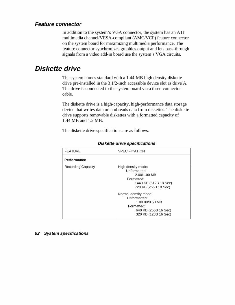
Diskette drive The system comes standard with a 1.44-MB high density diskettedrive pre-installed in the 3 1/2-inch accessible device slot as drive A.The drive is connected to the system board via a three-connectorcable.
The diskette drive is a high-capacity, high-performance data storagedevice that writes data on and reads data from diskettes. The diskettedrive supports removable diskettes with a formatted capacity of1.44 MB and 1.2 MB.
The diskette drive specifications are as follows.
Diskette drive specifications
FEATURE SPECIFICATION
Performance
Recording Capacity High density mode: Unformatted: 2.00/1.00 MB Formatted: 1440 KB (512B 18 Sec) 720 KB (256B 18 Sec)
Normal density mode: Unformatted: 1.00.00/0.50 MB Formatted: 640 KB (256B 16 Sec) 320 KB (128B 16 Sec)
System specifications 93
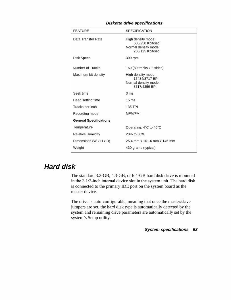
Diskette drive specifications
FEATURE SPECIFICATION
Data Transfer Rate High density mode: 500/250 Kbit/secNormal density mode: 250/125 Kbit/sec
Disk Speed 300 rpm
Number of Tracks 160 (80 tracks x 2 sides)
Maximum bit density High density mode: 17434/8717 BPINormal density mode: 8717/4359 BPI
Seek time 3 ms
Head setting time 15 ms
Tracks per inch 135 TPI
Recording mode MFM/FM
General Specifications
Temperature Operating: 4°C to 46°C
Relative Humidity 20% to 80%
Dimensions (W x H x D) 25.4 mm x 101.6 mm x 146 mm
Weight 430 grams (typical)
Hard disk The standard 3.2-GB, 4.3-GB, or 6.4-GB hard disk drive is mountedin the 3 1/2-inch internal device slot in the system unit. The hard diskis connected to the primary IDE port on the system board as themaster device.
The drive is auto-configurable, meaning that once the master/slavejumpers are set, the hard disk type is automatically detected by thesystem and remaining drive parameters are automatically set by thesystem’s Setup utility.
94 System specifications
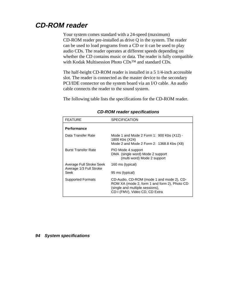
CD-ROM reader Your system comes standard with a 24-speed (maximum)CD-ROM reader pre-installed as drive Q in the system. The readercan be used to load programs from a CD or it can be used to playaudio CDs. The reader operates at different speeds depending onwhether the CD contains music or data. The reader is fully compatiblewith Kodak Multisession Photo CDs™ and standard CDs.
The half-height CD-ROM reader is installed in a 5 1/4-inch accessibleslot. The reader is connected as the master device to the secondaryPCI/IDE connector on the system board via an I/O cable. An audiocable connects the reader to the sound system.
The following table lists the specifications for the CD-ROM reader.
CD-ROM reader specifications
FEATURE SPECIFICATION
Performance
Data Transfer Rate Mode 1 and Mode 2 Form 1: 900 Kbs (X12) -1800 Kbs (X24)Mode 2 and Mode 2 Form 2: 1368.8 Kbs (X8)
Burst Transfer Rate PIO Mode 4 supportDMA (single word) Mode 2 support
(multi word) Mode 2 support
Average Full Stroke SeekAverage 1/3 Full StrokeSeek
160 ms (typical)
95 ms (typical)
Supported Formats CD-Audio, CD-ROM (mode 1 and mode 2), CD-ROM XA (mode 2, form 1 and form 2), Photo CD(single and multiple sessions),CD-I (FMV), Video CD, CD Extra
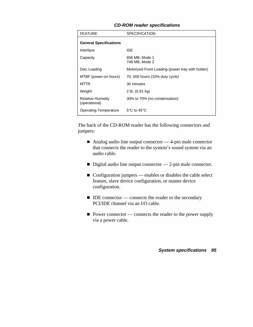
System specifications 95
CD-ROM reader specifications
FEATURE SPECIFICATION
General Specifications
Interface IDE
Capacity 656 MB, Mode 1748 MB, Mode 2
Disc Loading Motorized Front Loading (power tray with holder)
MTBF (power-on hours) 70, 000 hours (10% duty cycle)
MTTR 30 minutes
Weight 2 lb. (0.91 kg)
Relative Humidity(operational)
30% to 70% (no condensation)
Operating Temperature 5°C to 45°C
The back of the CD-ROM reader has the following connectors andjumpers:
� Analog audio line output connector — 4-pin male connectorthat connects the reader to the system’s sound system via anaudio cable.
� Digital audio line output connector — 2-pin male connector.
� Configuration jumpers — enables or disables the cable selectfeature, slave device configuration, or master deviceconfiguration.
� IDE connector — connects the reader to the secondaryPCI/IDE channel via an I/O cable.
� Power connector — connects the reader to the power supplyvia a power cable.
96 System specifications
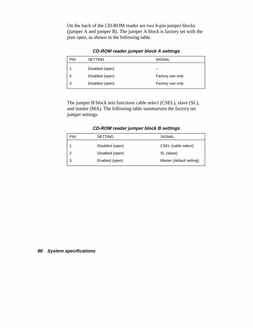
On the back of the CD-ROM reader are two 6-pin jumper blocks(jumper A and jumper B). The jumper A block is factory set with thepins open, as shown in the following table.
CD-ROM reader jumper block A settings
PIN SETTING SIGNAL
1 Disabled (open) –
2 Disabled (open) Factory use only
3 Disabled (open) Factory use only
The jumper B block sets functions cable select (CSEL), slave (SL),and master (MA). The following table summarizes the factory setjumper settings.
CD-ROM reader jumper block B settings
PIN SETTING SIGNAL
1 Disabled (open) CSEL (cable select)
2 Disabled (open) SL (slave)
3 Enabled (open) Master (default setting)
System specifications 97
Keyboard The Microsoft® Natural® Keyboard is an ergonomically designed104-key Windows keyboard. The keyboard features an attractivedesign that provides a comfortable alternative to standard keyboards.
The keyboard encourages a balanced natural hand position throughuse of a split and angled keypad layout. The keys are arranged in astaggered QWERTY layout. An adjustable hinged rail at the base ofthe keyboard allows a straighter wrist position while typing. Thekeyboard also has a built-in palm rest.
Other features include:
� two Windows 95 keys (marked with Windows logo) foraccessing the Windows 95 Start button
� a Windows 95 programmable application key (marked withmenu logo and arrow) for accessing sub menus in applicationprograms (acts the same as clicking the mouse right button)
� mouse cursor control from the numeric keypad — four cursorfeatures including Snap To, Sonar, Pointer Wrap, and FastMove
� function keys — 12 keys, capable of up to 48 functions
� status lamps — numeric lock, capital lock, and scroll keys
� numeric keyboard — standard
� separate cursor control keys — standard.
The keyboard has a six-foot coiled cable with a 6-pin mini-DINconnector for connecting to the system.
98 System specifications
Mouse The Microsoft® IntelliMouse™ is a PS/2-compatible, 400 dots perinch (dpi) unit. The two buttons on the top of the unit are standardmomentary contact buttons used for mode selection.
A scrolling wheel between the two buttons is used to scroll verticallyand horizontally on the monitor screen and to zoom in on data on thescreen. The mouse is controlled by Microsoft® IntelliPoint™ softwarepreinstalled at the factory.
A rolling ball on the bottom of the mouse moves the cursor on themonitor screen at a maximum speed of five inches per second in boththe X and Y axis.
The mouse has a self-cleaning mechanism that prevents a buildup ofdust or lint around the mouse ball and tracking mechanism.
A six foot straight cable with a 6-pin mini-DIN connector is attachedto the mouse.
Fax/modem/sound board Modem configured systems come with the fax/modem/sound boardpre-installed. The board provides sound, fax, and modem capabilities.Connectors on the board include a fax/modem port, microphone injack, line in jack, line out jack, and MIDI/joystick connector. Asplitter cable that comes with the system allows connection of theboard to a wall phone jack and a telephone.
The sound portion of the board is compatible with SoundBlaster™Pro™, SoundBlaster 2, Ad Lib™, MPU-401, and Microsoft®
Windows Sound System™ for PC sound applications.
System specifications 99
The fax/modem portion of the board and the NEC Connectionscommunications software provide modem, fax, full-duplexspeakerphone, and voicemail capabilities. The board comes with a52-Kbps (kilobytes per second) data/14.4-Kbps fax modem. Theboard also supports data transfer at 56 Kbps outside of the U.S.
See the following for fax/modem/sound board features.
Sound Features of the sound portion of the board include:
� music synthesizer
� surround sound
� MIDI interface
� wavetable synthesis.
The music synthesizer uses a 16-bit stereo Frequency Modulation(FM) synthesizer. FM synthesis exploits the fact that modulating onewaveform with another waveform produces a waveform with manymore harmonics than were present in the modulator or carrier (themodulated waveform).
The frequency of the modulator-to-carrier determines whichharmonics result. The amount of modulation determines how many ofthe potential harmonics result. Using integer and non-integer ratiosallow the application to create rich harmonics and inharmonic sounds.
Surround sound, also called SRS 3D sound, is a Sound RetrievalSystem®. The system creates a three-dimensional sound image withonly two conventional speakers. Using pre-recorded music, thesystem retrieves the spatial information and restores the originalthree-dimensional sound field. The reproduced sound is much closerto a live performance.
100 System specifications
The MIDI interface provides a musical instrument digital interfaceand connector for the connection of a digital musical instrument. Theconnector can also be used as a game port.
The board supports software or hardware wavetable functionality(depending on system configuration) for wavetable synthesis.Wavetable synthesis provides capabilities for producing extremelyhigh fidelity stereo music for computer audio systems.
The sound portion of the board is based on the Aztech AZT2320R2audio chip. Chip features include:
� 16-bit stereo FM music synthesizer
� 16-bit stereo digital sound recording and playback
� selectable sample rates up to 48 KHz stereo
� full duplex drivers for simultaneous audio playback andrecording
� wavetable synthesis
� built-in six-channel multimedia PC compatible stereo mixer
� dynamic range exceeds 80 dB with digital interpolation filter
� automatic dynamic filtering programmable to sampling rate
� Sound Retrieval System (SRS) for 3D sound effects.
System specifications 101
Fax/modem The data/fax/speakerphone functionality is based on the TMS320X2DSP chip on the modem board. Features include:
Speakerphone Full duplex, echo cancellation
Protocols and Compatibility’s
� Data (maximum speed)
X2 52/56 Kbps (Internet access)
ITU-T V.34bis (33,600 bps)
V.34 (28,800 bps)
V.32bis (14,400 bps)
V.32 (9000 bps)
V.22bis (2400 bps)
V.22 (1200 bps)
Bell 212A (1200 bps)
Bell 103 (300 bps)
� Data Compression ITU-T V.42bis/MNP5 for throughputup to 115,200 bps
� Error Control ITU-T V.42/MNP1-4
� Fax (maximum speed)
ITU-T V.17 (14,400 bps)
V.29 (9600 bps)
V.27ter (4800 bps)
V.21 Ch. 2 (300 bps)
102 System specifications
Firmware
� VoiceView™ support
� ADPCM voice operation
� DTMF tone detection/generation.
Graphics board All Ethernet configured systems come with a Diamond graphics boardcontaining a Trident ™ 3DImàge975™ video controller. The board isa high-performance PCI graphics board specifically designed forexceptional graphics and superior quality full-screen, full-motionvideo.
The Trident 3DImàge975 graphics video controller on the graphicsboard integrates 3D, 2D, and video accelerators to give you:
� outstanding TV-quality or leading-edge video playback
� accelerated multimedia and application performance
� brilliant true color graphics
� razor-sharp photo-realistic images
� ultra-fast game action
� TrueVideo® image enhancement
� third-generation TV-output
� texture mapping performance for 3D games, 3D Webbrowsing, 3D presentation, and other 3D applications.
System specifications 103
The graphics board comes with 4 MB of EDO memory. With 4 MBof memory, the board supports the following resolutions and colors:
� 1280 by 1024 pixels, 256 colors
� 1024 by 768 pixels, 256/64,000 colors
� 800 by 600 pixels, 256/64,000/16.8 million colors
� 640 by 480 pixels, 16/256/64,000/16.8 million colors.
Your system comes set at high color (800 by 600 with 64,000colors). Run the NEC Help Center at the high color video displayresolution.
Ethernet network board The 3Com® 3C905-TX Fast EtherLink 10/100 PCI network boardcomes preinstalled in all Ethernet configured systems. The boardcontains a single RJ-45 connector for either a 10 MB/second or a 100MB/second Ethernet network connection.
Three LED indicators on the board indicate link status, activity status,and 100 MB/second status. The green link status LED lites toindicate connection to an active network. An amber activity statusLED lites in either the 10 or 100 MB/second mode when receiving ortransmitting. The 100 MB/second amber status indicator lights whenthe 100 MB/second mode is selected.
Device drivers are preinstalled on all Ethernet configured systems.

104 System specifications
Game pad The Microsoft® SideWinder
® Game Pad contains six gaming action
buttons, two trigger buttons, start button, M button, and an eight-waycross-key pad for the ultimate in gaming action. The Game Pad canbe daisy chained with up to four pads for interactive action.
The Game Pad connects to the MIDI port on the back of the systemunit.
Environmental specifications The system’s environmental specifications are as follows.
Temperature:Non-operating — -40°C to 70°COperating — +0°C to 55°C
Humidity:Non-operating — 92% relative humidity maximum at 36°COperating — 80% relative humidity at 36°C
Altitude:Non-operating — 50,000 feet (15,240 meters)Operating — 10,000 feet (3,048 meters)
Index-1
BBattery
CMOS, 89BIOS, 87
CCables
connecting, 45diskette drive, 41diskette drive signal, 43, 47IDE, 41, 45identifying, 41power, 41, 42
CD-ROM reader, 94jumper settings, 95specifications, 94
CMOSbattery, 89
COM ports, 72settings, 72
Communication ports, 72settings, 72
Configuration jumpers, 74Cover
removing, 8replacing, 13
DDIMM sticks, 16DIMMs, 84
sockets, 85Diskette drive
connecting, 47signal cable, 43, 47specifications, 92
EEnvironmental specifications, 104Ethernet network board, 103Expansion boards
installing, 23removing, 28slots, 25
External devicesconnecting an NEC C700
monitor, 66connecting an NEC CS500
monitor, 64External options, 59
adding, 59connecting a printer, 68locating connectors, 60
Index
Index-2
FFax/modem, 101Fax/modem/sound board
specifications, 98Feature connector, 92Features
inside your computer, 11system board upgrade sockets and
connectors, 12
GGame pad, 104Graphics accelerator, 90
ATI Rage II, 90Graphics board, 102
specifications, 102Trident 3DImage975
controller, 102
HHard disk, 93
cabling, 45
II/O ports, 88IDE cables, 45IDE connectors, 40IDE devices
cables, 41, 45connecting, 45
IDE ports, 88Installing options
cover removal, 8cover replacement, 13expansion boards, 23interrupts, 72, 73
removing a board, 28removing a memory module, 21storage devices, 39system memory upgrade, 15system processor, 31system resources, 72, 73
Interrupts, 73IRQ settings, 72IRQs, 73ISA expansion boards
adding, 24
JJumper settings, 74
CD-ROM reader, 95clearing password, 77system board, 74
KKeyboard, 97
specifications, 97
MMemory upgrade, 15Modem board, 98Mouse, 98
specifications, 98
NNetwork board, 103
OOptions
choosing, 2connecting external devices, 59
Index-3
PPassword
clearing, 77PCI chipset, 85PCI expansion boards
adding, 24PCI local bus, 86Plug and play, 91Power cables, 41, 42Power management, 91Power supply, 80Precautions, 3
connecting/disconnecting cables, 5handling computer parts, 4working inside the system, 4
Primary IDE connector, 40Printer
connecting, 68Processor, 31
adding, 35removing, 32
Processor jumpers, 74
SSecondary cache, 84Secondary IDE connector, 40Serial port, 72
settings, 72Specifications
BIOS, 87CD-ROM reader, 94DIMMs, 85diskette drive, 92environmental, 104Ethernet network board, 103fax/modem/sound board, 98, 101graphics board, 102
hard disk drive, 93I/O ports, 88IDE ports, 88keyboard, 97mouse, 98PCI chip set, 85PCI local bus, 86power supply, 80processor, 83secondary cache, 84system, 79system board, 82
Storage devicesconnecting cables, 45identifying cables, 41installing, 39, 48installing 3 1/2-inch hard disk, 48installing 5 1/4-inch devices, 52preparing, 40
System board, 82expansion board slots, 87jumpers, 74secondary cache, 84upgrade sockets and
connectors, 12System memory, 84System memory upgrade
adding memory modules, 19checking memory, 17installing memory modules, 15kits, 16removing a memory module, 21
System processor, 31, 83System resources, 71, 73
communication ports, 72viewing, 73
Index-4
System Specifications, 79System unit, 80
dimensions and weight, 81expansion board slots, 81storage device slots, 81
UUniversal serial bus, 89Upgrades
expansion boards, 23installing expansion boards, 23system memory, 16system processor, 31