Embed Size (px)
Citation preview
1 PROPRIETARY INFORMATION-WITHHOLD UNDER 10 CFR 2.390
4300 Winfielcl Rosel Warrenville , IL 60 ') !)5
Exelon Generation® 630 65 7 2000 Off ice
RS-18-129 10 CFR 50.90
October 19, 2018
U.S. Nuclear Regulatory Commission Attn: Document Control Desk Washington, DC 20555-0001
Braidwood Station, Units 1 and 2 Renewed Facility Operating License Nos. NPF-72 and NPF-77 NRC Docket Nos. STN-50-456 and STN-50-457
Subject: Supplement to License Amendment Request to Utilize TVEL TVS-K Lead Test Assemblies
References: 1. Letter from D. M. Gullatt (Exelon Generation Company, LLC) to U.S. Nuclear Regulatory Commission, "License Amendment Request to Utilize TVEL TVS-K Lead Test Assemblies," dated July 19, 2018 (ML 18204A 169)
2. Letter from J.C. Wiebe (NRC) to B.C. Hanson (EGC), "Braidwood, Units 1 and 2 - Supplemental Information Needed for Acceptance of Requested Licensing Action Regarding Utilization of TVEL TVS-K Lead Test Assemblies (EPID L-2018-LLA-0208)," dated October 1, 2018 (ML 18267A199)
In the Reference 1 letter, Exelon Generation Company, LLC, (EGC) requested an amendment to Renewed Facility Operating License No. NPF-72 for Braidwood Station, Unit 1 and NPF-77 for Braidwood, Unit 2. The proposed change would add a License Condition to Appendix C, "Additional Conditions," of the Braidwood Station Operating Licenses for Unit 1 and Unit 2, respectively, that authorizes the use of up to eight Joint Stock Company "TVEL" (Fuel Company of Rosatom) TVS-K lead test assemblies (L TAs) in non-limiting reactor core locations for operation and evaluation.
In response to Reference 2 and discussions with the NRC on October 1, 2018, supplemental information is being provided to support the NRC's review of the EGC request submitted on July 19, 2018. Attachment 2 contains the responses to the NRC request for supplemental information and includes information proprietary to TVEL. TVEL requests that Attachment 2 be withheld from public disclosure in accordance with 1 O CFR 2.390. An affidavit supporting this request is provided in Attachment 1. Attachment 3 contains a non-proprietary version of the responses where the proprietary content has been redacted.
Attachment 2 contains Proprietary Information. When separated from Attachment 2, this document is decontrolled.

October 19, 2018 U.S. Nuclear Regulatory Commission Page 2
EGC has reviewed the information supporting a finding of no significant hazards consideration, and the environmental consideration, that were previously provided to the NRC in Reference 1. The additional information provided in this submittal does not affect the bases for concluding that the proposed license amendments do not involve a significant hazards consideration. In addition, the information provided in this submittal does not affect the bases for concluding that neither an environmental impact statement nor an environmental assessment needs to be prepared in connection with the proposed amendments.
EGC is notifying the State of Illinois of this supplement to a previous application for a change to the operating license by sending a copy of this letter and its attachment to the designated State Official in accordance with 10 CFR 50.91, "Notice for public comment; State consultation," paragraph (b).
Approval of the proposed amendments continues to be requested by July 19, 2019.
There are no regulatory commitments contained in this letter. Should you have any questions concerning this letter, please contact Ms. Rebecca L. Steinman at (630) 657-2831.
I declare under penalty of perjury that the foregoing is true and correct. Executed on the 19th day of October 2018.
Respectfully,
.-----) y /M ,-J,:1/.1_ L-h '/-~--
David M, Gullatt Director - Licensing and Regulatory Affairs Exelon Generation Company, LLC
Attachments: 1 Affidavit Requesting to Withhold Proprietary Information Under 10 CFR 2,390 2 Response to NRC Request for Supplemental Information [Proprietary] 3 Response to NRC Request for Supplemental Information [Non-Proprietary]
cc: NRC Regional Administrator, Region Ill NRC Senior Resident Inspector, Braidwood Station Illinois Emergency Management Agency - Division of Nuclear Safety
ATTACHMENT 1 Affidavit Requesting to Withhold Proprietary Information Under 10 CFR 2.390
.Joint Stork Company T\'EL
AFFIDAVIT
L :\lc:xe~ · DolgoY. state a~ folluws:
(I) I am the Director nf R&D department of Joint Stock Company TVF.l. (TVELJ. and have been delegated the function of rc,·iewing the information dcscriheJ in paragraph ,,·hich is sought to he \\·ithhclcl. and have been authorized IP apply for its withholding.
('.n The information sought to be withheld as TVF.L proprietary information is contained in the i\ttachrnent to h:elon·s letter. ·'Supplement tL1 LiL·ense Amendment Request ln Uti lin: TVFL TVS-K I .cad Test r\ ssernblies .. dated October I lJ. 2018.
(3) In mJking this application ft1r withholding of proprietary infmmatinn of which 1t 1s the O\\ ner or licensee. TVFI. reli cs upnn the exemption frnm disclt isure set forth in the Fre1.·do111 of lnformatinn Act (FOIA}. 5 LISC Sec. 552(h)(4). and the Track Secrets /\ct 18 LSC Sec. 1905. and '\RC regul:itions 10 CTR 9.17(~1)(4). and 2.390(a)(4) f(.w trade st~crl'ls (Exemption 4 ). The mat erial for which exemption from disclnsure is here SLll1ght also qualifies under the narrower dctiniti on of trade secret. within the meanings assigned to those tenns for puq1oscs of FO[;\ Exemption 4 in. rcspecti,·cly. Critical i\'lass Encr~v Project v. >Juclcar Regulatorv Commission. 975 F2d 87 1 (DC Cir. 1992). and Public Citizen l lcalth Research Grou) v. FDA. 704 F2c1 1280 (DC Cir. I tJ83 ).
(4) ThL' infonnation snug.ht to be \\'ithhclcl is considered to he proprietary for till~ rcasnns set forth in pciragraphs (-1-)a. and (4)h. Sume examples (\r categories of inl(mnatinn that fit into the definition ofpn1prietary inf(mnation arc:
a. lnf(1nnatio11 that disclt)Scs a process. method. t1r apparatus. including supporting data and analyses, \\here prcvcntiL)ll or its USC by TVEL's cnmpctitnrs \\·ithl1ut license from TVEL constitutes a CL)mpctitive economic advantage over TVEL and /or other companies.
b. l11l(i1111 at ion that. if used by a CL)mpetitor. would reduce their expenditure of resources or impro\L' their competitive position in the design. manufacture. shipment. installation. assurance of quality. or licensing of a similar 1m1duct.
c. lnfnnnatinn that rcYeals aspects (If past. present. or future TVEL cust11mer-funded de\l~lopmcnt plans and proh'l"<lms. that may include potential prmlucts ofTVEL.
cl. lnfonnati on th~1t discloses trade secret and ·or potentially patentable subject matter l(w \\'hich it may be desirable to obtain patent protccti\)n.
( 5 l To address I 0 CFR 2.'.i90(h )( 4 ). the inl(irniatiun sought to be withheld is being submitted tn the >!RC in cnnlidcncc. The infrmnation is of a sort customarily held in confidence by TVEL. and is in fact so held. The infonnation Sl1ught to be withheld has. tt1 the best uf my knowledge and belief consistently been held in conficknce by TVEL. 11lit been disclosed publicly. and not been made <n·ailablc in public sources. All disclosures to third parties. including any required transmittals to the !\RC. ha\·e
T\T l. T\ 'S -K RSI .\tfal;n it :\ffida\ i1 Page I uf 3
ATTACHMENT 1 Affidavit Requesting to Withhold Proprietary Information Under 10 CFR 2.390
been made. nr rnust he made. pursuant lo regulatory prm htons t)r proprietary and/or cpnfidcntiality agreements that provide for maintaining the information in C1mfidcnce. The initi al d<:.·signation 11f th is information as proprietary information. and the subsequent skps taken to pre\·ent ih unauthori/ed disclosure arc as set f\1rth in the following paragraphs (6) and (7).
((1) lniti al appro,·al of proprietary treatment of a dncument is made by the manager of the (1rigi11ating cornponent. who is the person m(lst likely to be acquainted '' ith the value and sensit i\·ity of the information in relation tP industry knowledge. or who is thL· persc111 mnst likely t11 he subject tu the terms under ,,·hich it was licensed tu TVLL.
( 7 ) The procedure f\) r apprm·al of external release of sud1 a docum<:.'lll typically require~ re,·iew by the staff manager. pn1ject manager. princi pal scientist. or tither equiqilent <lllthority for technical content. L·ornpetili\'C effect. and dctc1111inatilln of the accuracy nf the 1m1prictary dc~ignatiun. Discltisures ouhide TVEL arc limited to regulatory bodies. customers. and pl1tcntial cu~Wrners. and their agents. suppliers. and licensees. and others '' ith a legitimate need fur the inforrnatilln. and then only in accordance ,,·irh apprupriall' regulatury pn•\ 1s1011~ (\I" pruprictciry and 'or confidentiali tv agreements.
( S) The in formation identified in paragraph ( 2) ahP1e is classi ficd as proprietary because it contains details of TVEL" s fuel (k:;ign for the Pressurized \Vater Reactor (i'\VR). Dc\doprnrnt of this information ~md their application frir the design. modilication. and analyses rncthudulngies and pnicesscs \\'as achic\ccl at a signi !ieant cnst to TVEL. The dc\elupmcnt pf the C\ aluation process along with the interpretation and applicatitin of the analyti cal results is ckri\ eel from the e\.tcnsi\ c experience database that constitutes a major TVEI. a~set.
(9) Public disclt1surc of the infnrrnat ion sought to he 11·ithhclcl is likely to cause -:;ubstant ial harm to TVE L\ compctiti\·c position and !"i.1rcclosc or reduce the availability of pn1lit-making oppn11unitics. The !"ucl design i~ part of TVEL's cnrnprchensin· P\VR safety anJ tcclrnolngy base. ;ind its commercial value extends heynnd the original de\ clopmcnl cost. The val UC or the lcchnulogy base gues beyond the extensiv<c' physical database and analy1ical methodology and includes development pf the c\pertisc to determine and appl y the appropri ate c\·aluatinn process. In add ition. the tcchill)lngy base includes the \·aluc derived fnl lll p1\)\'iding analyses ch111c ,,·ith 'JRC-appn)\cd methods.
The rcsearl·li. dc,-clopment. cngi nccri ng. analyt ical and :\RC re\ ic\\" CtlSts mm prise a substantial i11\"CSt111c111 of time and money by TVEL. The precise\ alue of the expertise to dc\isc an c\"aluation prnccss and appl y the cnrreet analyticul methodology is difficult to quantify. hut it clearly is substantial. T\'EL's cornpeti ti \c ad\antage \\ill he lost if its competitors arc able to use the results of the TVEL c:-;pericnce to normalize or \'crify their own p1\1ccss i1r if they are able to claim an cqui1·alcnt understanding by ckmonstrati ng that they can arri\c at the same nr similar conclusions.
The value tif thi s infonnation to T\'EL would be lost if the information were disclosed to the public. \laking such infonnatinn available to competit0rs without their having been requi red to undertake a simil ar expenditure of resources would unfairly prnvide competitors with a \\indfoll. and depri\'e TVEL of the npprn1unity tu exercise its
IVF L T\ 'S-K RSI .'\ t"lida,it Affida\ it !'age ~ nf ."\
ATTACHMENT 1 Affidavit Requesting to Withhold Proprietary Information Under 10 CFR 2.390
i.'<Hnpetiti\·e ackaniagt:.'. tn scd an adequate ret urn tin ih large investment in dcvck1pi11g and nhuining these:' cry' aluabk analytical to1)ls.
I <kcbrc under pcn<ilty or pe1jury that the !i.ircgoing afficht\ it and the mailers stated therein arc true and correct to the hesl or my kno\\'lcdge. information. and ht:.'lief.
I ckclarc under penalty or pl'.1jury tha1 the kircgoing is true and cmrect.
I ···~ .
/~ ·
.\kxey Dnlgu\ Director of R&D dcpanme11t .luint Stnck Company TVLL 49. Kash i rs hue shossc !\ losctl\\'. I I :'\..J.09. Ru-;sia ABDPlg<1\ (u l\ cl .ru
.-\ftiJa\ it Pa1'..: 3 ur 3
ATTACHMENT 3 Response to NRC Request for Supplemental Information [Non-Proprietary]
Introduction
The TVS-K lead test assembly (L TA) program at Braidwood is designed to collect the data necessary to develop and seek future NRG-approval of codes and methods for the generation of the core operating limits for batch loading. The license amendment request (LAR) for the Braidwood TVS-K LT A program is based on the LT A provision in Braidwood Technical Specification (TS) 4.2.1 that restricts L TAs to limited numbers in non-l imiting core locations.
Exelon Generation Company, LLC (EGC) will demonstrate compliance with the L TA provision that L TAs are of "l imited number" and "in nonlimiting core regions" through an evaluation that shows that the quantity and placement of the L TAs will not invalidate either the Updated Safety Analysis Report (USAR) Chapter 15 transient and accident analyses or the core operating limits report (COLR).
The "l imited number" provision of TS 4.2.1 is based on the degree of characterization of material properties and known performance of an assembly design. As described in the EGC LAR dated July 19, 2018, the TVS-K assembly was designed for use in Westinghouse 3 and 4 loop reactors; therefore, the TVS-K L TAs have a high degree of mechanical , nuclear, and thermal-hydraulic compatibility with the Westinghouse VANTAGE+ Optimized Fuel Assemblies currently in use at the Braidwood Station. Operation of eight L TAs of such similar hydraulic and nuclear response gives a high degree of confidence that core nuclear and hydraulic response is unaffected by the new fuel assemblies. Eighth core symmetry is often used to adequately represent cores, even with small local differences between exposed fuel assemblies. Therefore, eight such assemblies are deemed a reasonable definition of "lim ited number" for such fuel types. The responses to Questions 2 and 3 below provide additional details regarding the current state of development of the TVS-K fuel design regarding the critical heat flux (CHF) testing and specific irradiated material properties that support the conclusion that eight L TAs meet the "limited number" provision of TS 4.2.1. Additionally, the number of L TAs is limited to eight to meet the GSl-191 restrictions on mixed cores described in WCAP-16793-NP-A, "Evaluation of Long-Term Cooling Considering Particulate, Fibrous, and Chemical Debris in the Recirculating Fluid" (ADAMS Accession No. ML 13239A 113).
The original LAR submittal dated July 19, 2018 (ADAMS Accession No. ML 18204A 169) described the methods that will be used to ensure the TVS-K L TAs are not leading the core.
Braidwood Station, Units 1 and 2
RSI 1
In its letter dated July 19, 2018, the licensee states that the VIPRE-01 thermal hydraul ic computer code will be used to evaluate departure from nucleate boiling and thermal hydraulic related design constraints. The NRC staff has reviewed and found this code to be acceptable for pressurized-water reactor (PWR) applications; however, the staff safety evaluation clearly states that this approval is conditional on appropriate justification for the input selection and modeling assumptions (Reference 1 ). The licensee does not provide sufficient detail for the NRC staff to determine if the input selection and model ing assumptions are appropriate for this intended purpose, nor does it provide an applicable precedent to inform the NRC staff's understanding of the proposed approach. Provide a
Page 1 of 22
ATTACHMENT 3 Response to NRC Request for Supplemental Information [Non-Proprietary]
description and justification of the input, modeling assumptions, and methodology application that will be used in the GNF-A (Global Nuclear Fuels - America) VIPRE-01 analysis.
Reference
Letter from A. C. Thadani (NRC) to Y. Y. Yung (WPPSS), "Acceptance for Referencing of the Modified Licensing Topical Report, EPRI NP-2511-CCM, Revision 3, 'VIPRE-01: A Thermal Hydraulic Analysis Code for Reactor Cores,' (TAC NO. M79498)," dated October 30, 1993, ADAMS Accession No. ML 18033A074.
EGC Response to RSI 1
VIPRE-01 is a computer code developed for EPRI by Battelle Pacific Northwest Laboratories in order to perform detailed thermal-hydraulic analyses of reactor cores. VIPRE-01 has been widely used for PWR safety analyses and has been approved by the USNRC for PWR licensing applications (References 1-1 and 1-2). A brief description of the application of VIPRE-01 to the Braidwood Station TVS-K LTA program is provided below.
Thermal-hydraulic design for the resident VANTAGE+ fuel will be evaluated using the existing NRG-approved Westinghouse methods, operating conditions, and reload designs applicable to the Braidwood Station as described in TS 5.6.5, "Core Operating Limits Report (COLA)."
Thermal-hydraulic design for TVEL TVS-K fuel will be evaluated using methodology consistent with existing NRG-approved methods as described in VIPRE-01 Licensing Topical Reports (L TRs) submitted by Dominion (Reference 1-3) and Westinghouse (Reference 1-4). For TVS-K LTA implementation at the Braidwood Station, a GNF-A VIPRE-01 model will be developed [[
]]. Operating conditions and reload design information applicable to Braidwood Station are supported. A brief description of the GNF-A VIPRE-01 model inputs, modeling assumptions, and methodology application is provided below.
Radial Nading
A one-eighth core model with the hot assembly located at the center of the core will be used for analysis. This representation is sufficient when assuming the radial power distribution has one-eighth core symmetry. The core model will include [[
]]
Page 2 of 22
ATTACHMENT 3 Response to NRC Request for Supplemental Information [Non-Proprietary]
Axial Nodinq
The finite difference method used in VIPRE-01 requires that sufficient axial nodes be provided to resolve the details of the flow field and axial power profiles. The GNF-A TVS-K model will be consistent with Dominion model recommendations (Reference 1-3), which use axial nodes of approximately 2 inches in the Minimum DNB Ratio (MDNBR) region. The GNF-A TVS-K model will also adopt Dominion's nodalization scheme that places all the mixing and non-mixing vane grids at the upper edges of the axial nodes for better numerical convergence, while preserving the actual grid spacing. This approach places the grids in the location where VIPRE-01 applies the pressure loss (top edge of node).
The active fuel height will not be adjusted for fuel densification. For TVEL's low densification fuel, the amount of fuel densification is off-set by the fuel thermal expansion. Therefore, the use of the cold nominal active fuel length will be adopted as a conservative approach. This approach is consistent with the NRC-approved Duke model for Westinghouse plants in Reference 1-5.
Time-step transient modeling is not required for the Braidwood L TA program submittal. Therefore, Courant restrictions on the axial node length to ensure numerical stability are not pertinent to the TVS-K LT A model.
Fuel Rod Modeling
VIPRE-01 is designed to simulate heat conduction in nuclear fuel rods and electrically heated rods, tubes, or plates. VIPRE-01 has an option to specify the heat input directly to a channel using "dummy" rods, with the surface heat flux treated as a boundary condition on the fluid solution. The "dummy" rod model will be adopted for the Braidwood TVS-K LTA evaluation. No calculation of heat conduction and temperature distribution within the fuel rods will be performed. Unheated rods such as guide thimble tubes and instrument tubes will be used in calculating the subchannel geometry parameters but will not be considered for heat transfer.
The dummy rod model is typically used in steady state DNBR calculations and is consistent with the approach in other NRC-approved VIPRE models (References 1-3 and 1-4).
The TVS-K VIPRE-01 model will account for a fraction of the core power being generated directly in the coolant due to gamma heating and neutron absorption. The Braidwood model conservatively assumes that [[ ]] of the reactor power will be generated within the fuel rods, and the remaining [[ ]] will be generated directly in the coolant. This amount of direct moderator heating is consistent with many plant safety analyses in the US PWR fleet (References 1-3 and 1-4).
Power Distributions
In the TVS-K VIPRE-01 fuel rod model, each fuel rod is assigned a radial power factor and an axial power shape. The radial power factor specifies the amount of the total power the rod receives relative to the average power per rod. The axial shape determines how the input power is distributed axially. With dummy rods, the input power and individual rod
Page 3 of 22
ATTACHMENT 3 Response to NRC Request for Supplemental Information [Non-Proprietary]
radial and axial power factors are used to define the heat flux boundary condition on the coolant.
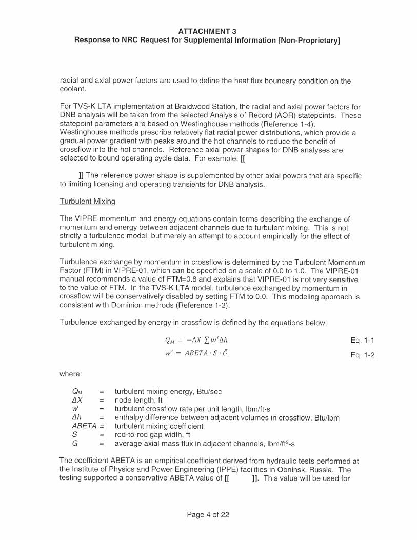
For TVS-K L TA implementation at Braidwood Station, the radial and axial power factors for DNB analysis will be taken from the selected Analysis of Record (AOR) statepoints. These statepoint parameters are based on Westinghouse methods (Reference 1-4). Westinghouse methods prescribe relatively flat radial power distributions, which provide a gradual power gradient with peaks around the hot channels to reduce the benefit of crossflow into the hot channels. Reference axial power shapes for DNB analyses are selected to bound operating cycle data. For example, [[
]] The reference power shape is supplemented by other axial powers that are specific to limiting licensing and operating transients for DNB analysis.
Turbulent Mixing
The VIPRE momentum and energy equations contain terms describing the exchange of momentum and energy between adjacent channels due to turbulent mixing. This is not strictly a turbulence model, but merely an attempt to account empirically for the effect of turbulent mixing.
Turbulence exchange by momentum in crossflow is determined by the Turbulent Momentum Factor (FTM) in VIPRE-01, which can be specified on a scale of 0.0 to 1.0. The VIPRE-01 manual recommends a value of FTM=0.8 and explains that VIPRE-01 is not very sensitive to the value of FTM. In the TVS-KL TA model, turbulence exchanged by momentum in crossflow will be conservatively disabled by setting FTM to 0.0. This modeling approach is consistent with Dominion methods (Reference 1-3).
Turbulence exchanged by energy in crossflow is defined by the equations below:
where:
QM = L1X = w = L1h = ABETA= s = G =
QM = - IJ.X l;w'!J..h
w I = AB ET A . s . G
turbulent mixing energy, Btu/sec node length, ft turbulent crossflow rate per unit length, lbm/ft-s enthalpy difference between adjacent volumes in crossflow, Btu/lbm turbulent mixing coefficient rod-to-rod gap width, ft average axial mass flux in adjacent channels, lbm/ft2-s
Eq. 1-1
Eq. 1-2
The coefficient ABETA is an empirical coefficient derived from hydraulic tests performed at the Institute of Physics and Power Engineering (IPPE) facilities in Obninsk, Russia. The testing supported a conservative ABETA value of [[ ]]. This value will be used for
Page 4 of 22
ATTACHMENT 3 Response to NRC Request for Supplemental Information [Non-Proprietary]
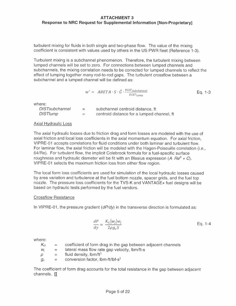
turbulent mixing for fluids in both single and two-phase flow. The value of the mixing coefficient is consistent with values used by others in the US PWR fleet (Reference 1-3).
Turbulent mixing is a subchannel phenomenon. Therefore, the turbulent mixing between lumped channels will be set to zero. For connections between lumped channels and subchannels, the mixing correlation needs to be corrected for lumped channels to reflect the effect of lumping together many rod-to-rod gaps. The turbulent crossflow between a subchannel and a lumped channel will be defined as:
where: DISTsubchannel DIST/ump
Axial Hydraulic Loss
= =
w'= ABET A . S. G. DISTsubchannel DIST1ump
subchannel centroid distance, ft centroid distance for a lumped channel, ft
Eq. 1-3
The axial hydraulic losses due to friction drag and form losses are modeled with the use of axial friction and local loss coefficients in the axial momentum equation. For axial friction, VIPRE-01 accepts correlations for fluid conditions under both laminar and turbulent flow. For laminar flow, the axial friction will be modeled with the Hagen-Poiseuille correlation (i.e., 64/Re). For turbulent flow, the implicit Colebrook formula for a fuel-specific surface roughness and hydraulic diameter will be fit with an Blasius expression (A Re8 + C). VIPRE-01 selects the maximum friction loss from either flow region.
The local form loss coefficients are used for simulation of the local hydraulic losses caused by area variation and turbulence at the fuel bottom nozzle, spacer grids, and the fuel top nozzle. The pressure loss coefficients for the TVS-Kand VANTAGE+ fuel designs will be based on hydraulic tests performed by the fuel vendors.
Crossflow Resistance
In VIPRE-01, the pressure gradient (dP/dy) in the transverse direction is formulated as:
where: KG Wj p 9c
= = = =
dP Kclw11w1 dy 2pgcS
coefficient of form drag in the gap between adjacent channels lateral mass trow rate gap velocity, lbm/ft-s fluid density, lbm/ft3
conversion factor, lbm-ft/lbf-s2
Eq. 1-4
The coefficient of form drag accounts for the total resistance in the gap between adjacent channels. [[
Page 5 of 22
ATTACHMENT 3 Response to NRC Request for Supplemental Information [Non-Proprietary]
]]
[[ ]] Eq. 1-5
[[ where:
In order to correctly calculate the effective crossflow resistance for the lumped channels, the subchannel crossflow resistance will be multiplied by the ratio of the lumped centroid distance and the subchannel centroid distance. This treatment is consistent with the VIPRE-01 Safety Evaluation Report (Reference 1-1 ).
Two-Phase Flow Correlations
VIPRE-01 has a number of empirical correlations available to simulate two-phase flow effects (Reference 1-1 ). The two-phase correlations fall into three categories: 1) subcooled void correlation, 2) bulk void model, and 3) two-phase friction multiplier. A subcooled void correlation is used for modeling the nonequilibrium transition from single phase to nucleate boiling. The bulk (saturated) void model relates flow quality with void fraction, which can account for phase slip. The two-phase friction multiplier is the means of modeling the effect of two-phase flow on the friction pressure drop with a homogeneous equilibrium model.
In the GNF-A TVS-K model, [[
]]
Boundary Conditions
The VIPRE-01 models require the following parameters as the input or boundaries for calculations:
• Core inlet temperature or enthalpy • Core average power • Core exit pressure • Core inlet flow rates • Core power distributions (including nuclear peaking factors)
The core inlet temperature and inlet flow may be uniform or non-uniform, depending on the core conditions being analyzed. The core power defines the thermal energy entering the fluid through the fuel rods. The core exit pressure distribution is assumed to be uniform
Page 6 of 22
]]
ATTACHMENT 3 Response to NRC Request for Supplemental Information [Non-Proprietary]
throughout the VIPRE-01 model. The core inlet flow conservatively excludes flow through bypass leakage, such as through the guide tubes.
For TVS-K LTA implementation at Braidwood Station, the boundary conditions for DNB analysis will be taken from the [[
]]
References for Response to RSI 1
1-2 Letter from C.E. Rossi (USNRC) to J.A. Blaidsell (UGRA Executive Committee), "Acceptance for Referencing of Licensing Topical Report, EPRI NP-2511-CCM, 'VIPRE-01: A Thermal-Hydraulic Analysis Code for Reactor Core' , Volumes 1, 2, 3, and 4," May 1, 1986 (ADAMS Accession No. ML 18033A075)
1-2 Letter from A.C. Thadani (USN RC) to Y.Y. Yung (VIPRE-01 Maintenance Group), "Acceptance for Referencing of the Modified Licensing Topical Report, EPRI NP-2511 CCM, Revision 3, 'VIPRE-01: A Thermal-Hydraulic Analysis Code for Reactor Cores', (TAC No. M79498)," October 30, 1993 (ADAMS Accession No. ML 18033A074)
1-3 Dominion Energy, DOM-NAF-2-NP, "Reactor Core Thermal-Hydraulics Using the VIPRE-D Computer Code," Revision 0.2-NP-A, August 2010, nonproprietary (ADAMS Accession No. ML 102390419)
1-4 Westinghouse Electric Company, WCAP-15306-NP-A, "VIPRE-01 Modeling and Qualification for Pressurized Water Reactor Non-LOCA Thermal-Hydraulic Safety Analysis," October 1999, non-proprietary (ADAMS Accession No. ML993160096)
1-5 Letter from T.A. Reed (USRNC) to H.B. Tucker (Duke Power Company), "Safety Evaluation of Topical Report DPC-NE-3000, Thermal-Hydraulic Transient Analysis Methodology 9TAC Nos. 7365/73766/73767/73768/, ITS/NRC/91-2 Technical Evaluation," August 31, 1995, non-proprietary (ADAMS Accession No. ML 15118A390)
Page 7 of 22
ATTACHMENT 3 Response to NRC Request for Supplemental Information [Non-Proprietary]
In its letter dated July 19, 2018, the licensee states that a CHF correlation developed based on testing of the L TA design will be used with the VIPRE-01 computer code. The July 19, 2018 letter does not provide any detail regarding data used as a basis for the CHF correlation or why it is appropriate for this purpose. Provide a discussion on the CHF testing, explain how the data was used to develop a CHF correlation (including consideration of any uncertainties), describe how the correlation is used in VIPRE-01, and briefly summarize why it is appropriate for this application.
EGC Response to RSI 2
The Braidwood Technical Specification 4.2.1 contains the STS LTA provision that limits the number of L TAs in the core and restricts them to non-limiting locations. This allows the collection of data under actual reactor conditions to support the development of codes and methods for future batch applications. Although it is desirable to use NRG-approved methods, there are cases where approved methods for the LT A fuel may not exist. The TVS-K assembly-specific critical heat flux (CHF) correlation falls into this category. The remainder of this response provides additional details regarding the development of the CRK correlation for the TVS-K assembly intended for use in assessing LTA performance at the Braidwood Station.
Test Facilities Description
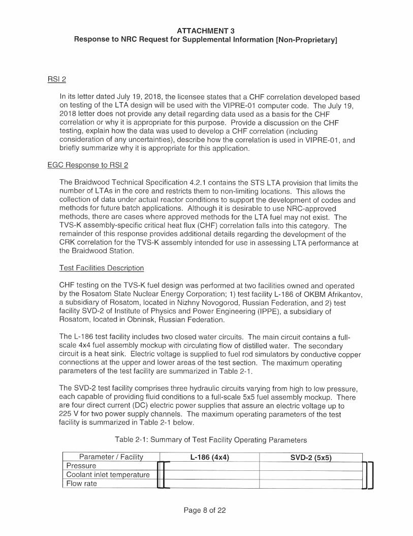
CHF testing on the TVS-K fuel design was performed at two facilities owned and operated by the Rosatom State Nuclear Energy Corporation; 1) test facility L-186 of OKBM Afrikantov, a subsidiary of Rosatom, located in Nizhny Novogorod, Russian Federation, and 2) test facility SVD-2 of Institute of Physics and Power Engineering (IPPE), a subsidiary of Rosatom, located in Obninsk, Russian Federation.
The L-186 test facility includes two closed water circuits. The main circuit contains a full-scale 4x4 fuel assembly mockup with circulating flow of distilled water. The secondary circuit is a heat sink. Electric voltage is supplied to fuel rod simulators by conductive copper connections at the upper and lower areas of the test section. The maximum operating parameters of the test facility are summarized in Table 2-1.
The SVD-2 test facility comprises three hydraulic circuits varying from high to low pressure, each capable of providing fluid conditions to a full-scale 5x5 fuel assembly mockup. There are four direct current (DC) electric power supplies that assure an electric voltage up to 225 V for two power supply channels. The maximum operating parameters of the test facility is summarized in Table 2-1 below.
Table 2-1: Summary of Test Facility Operating Parameters
Parameter I Facility L-186 (4x4) SVD-2 (5x5) Pressure Coolant inlet temperature Flow rate
Page 8 of 22
J
ATTACHMENT 3 Response to NRC Request for Supplemental Information [Non-Proprietary]
Test Procedure and Conditions
DNB investigations were performed on TVS-K models at the L-186 and SVD-2 test facilities. In each facility, under stable coolant properties, the fuel assembly was brought to DNB conditions by a step-wise increase of supplied electric power to the value at which the temperature in the inner cavity of any heater rod became non-proportionally high. Power was increased in steps of 1 % of the anticipated critical power value. The power value preceding the power step resulting in the non-proportional temperature growth was considered critical. The DNB location was determined by the location point of the first thermocouple to register the non-proportional temperature growth.
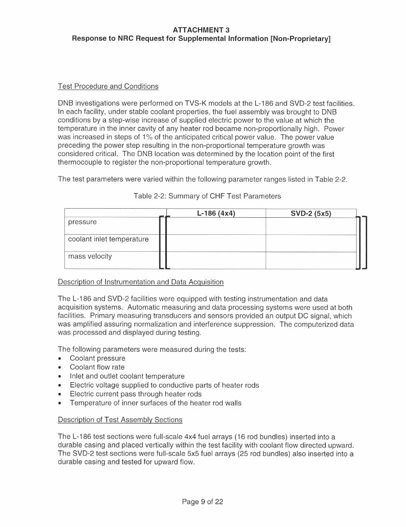
The test parameters were varied within the following parameter ranges listed in Table 2-2.
Table 2-2: Summary of CHF Test Parameters
- - L-186 (4x4) SVD-2 (5x5) pressure
coolant inlet temperature
mass velocity
Description of Instrumentation and Data Acquisition
The L-186 and SVD-2 facilities were equipped with testing instrumentation and data acquisition systems. Automatic measuring and data processing systems were used at both facilities. Primary measuring transducers and sensors provided an output DC signal, which was amplified assuring normalization and interference suppression. The computerized data was processed and displayed during testing.
The following parameters were measured during the tests: • Coolant pressure • Coolant flow rate • Inlet and outlet coolant temperature • Electric voltage supplied to conductive parts of heater rods • Electric current pass through heater rods • Temperature of inner surfaces of the heater rod walls
Description of Test Assembly Sections
The L-186 test sections were full-scale 4x4 fuel arrays (16 rod bundles) inserted into a durable casing and placed vertically within the test facility with coolant flow directed upward. The SVD-2 test sections were full-scale 5x5 fuel arrays (25 rod bundles) also inserted into a durable casing and tested for upward flow.
Page 9 of 22
ATTACHMENT 3 Response to NRC Request for Supplemental Information [Non-Proprietary]
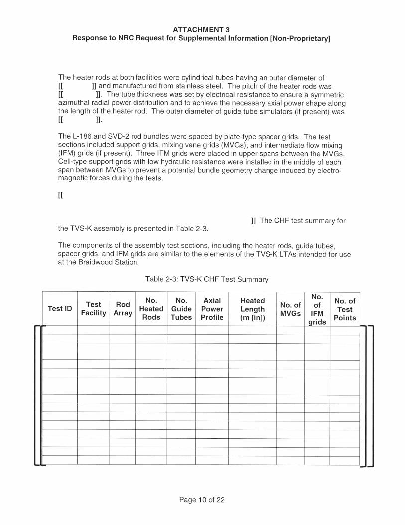
The heater rods at both facilities were cylindrical tubes having an outer diameter of [[ ]] and manufactured from stainless steel. The pitch of the heater rods was [[ ]]. The tube thickness was set by electrical resistance to ensure a symmetric azimuthal radial power distribution and to achieve the necessary axial power shape along the length of the heater rod. The outer diameter of guide tube simulators (if present) was [[ ]].
The L-186 and SVD-2 rod bundles were spaced by plate-type spacer grids. The test sections included support grids, mixing vane grids (MVGs), and intermediate flow mixing (IFM) grids (if present). Three IFM grids were placed in upper spans between the MVGs. Cell-type support grids with low hydraulic resistance were installed in the middle of each span between MVGs to prevent a potential bundle geometry change induced by electro-magnetic forces during the tests.
[[
]] The CHF test summary for the TVS-K assembly is presented in Table 2-3.
The components of the assembly test sections, including the heater rods, guide tubes, spacer grids, and I FM grids are similar to the elements of the TVS-K L TAs intended for use at the Braidwood Station.
Table 2-3: TVS-K CHF Test Summary
No. No. Axial Heated No. No. of Test ID Test Rod Heated Guide Power Length No. of of Test Facility Array MVGs IFM Rods Tubes Profile (m [in]) grids Points
Page 10 of 22
·-
- -
[[
ATTACHMENT 3 Response to NRC Request for Supplemental Information [Non-Proprietary]
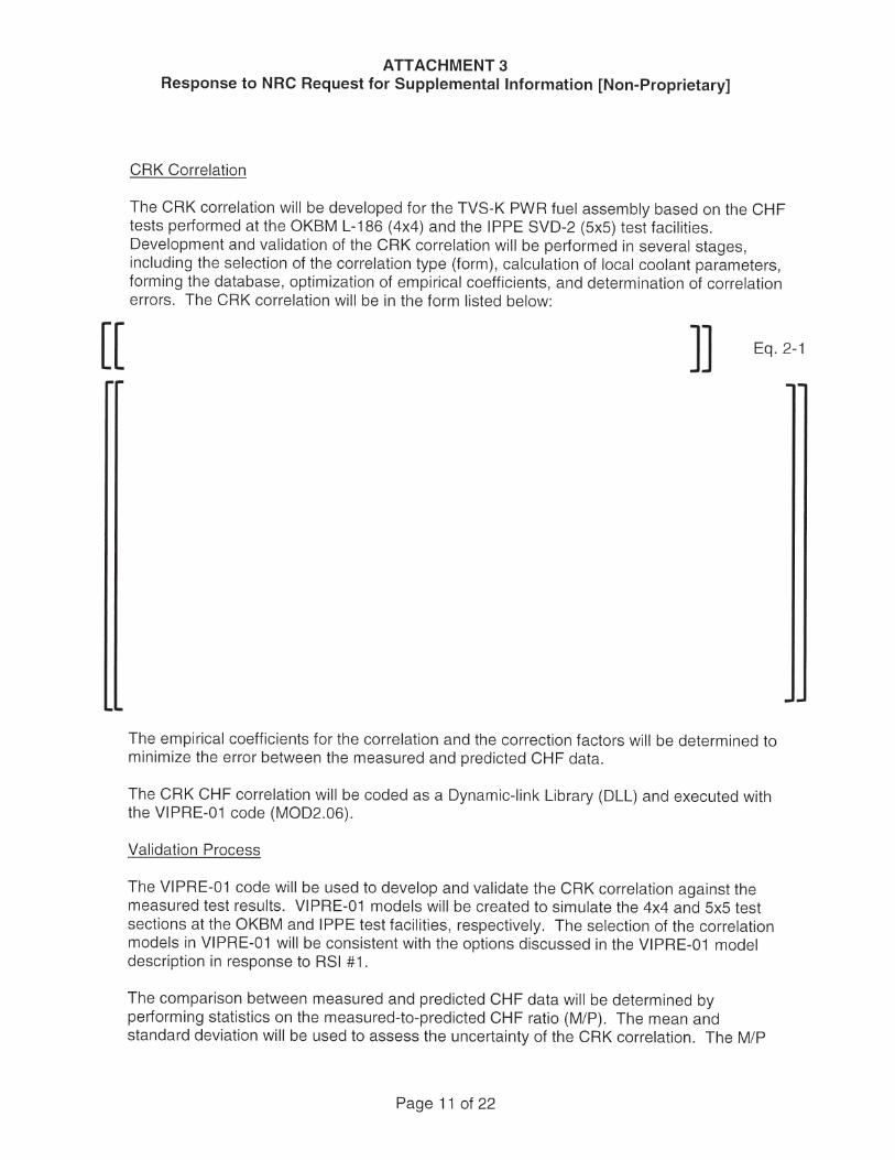
CRK Correlation
The CRK correlation will be developed for the TVS-K PWR fuel assembly based on the CHF tests performed at the OKBM L-186 (4x4) and the IPPE SVD-2 (5x5) test facilities. Development and validation of the CRK correlation will be performed in several stages, including the selection of the correlation type (form), calculation of local coolant parameters, forming the database, optimization of empirical coefficients, and determination of correlation errors. The CRK correlation will be in the form listed below:
]] Eq. 2-1
The empirical coefficients for the correlation and the correction factors will be determined to minimize the error between the measured and predicted CHF data.
The CRK CHF correlation will be coded as a Dynamic-link Library (DLL) and executed with the VIPRE-01 code (MOD2.06).
Validation Process
The VIPRE-01 code will be used to develop and validate the CRK correlation against the measured test results. VIPRE-01 models will be created to simulate the 4x4 and 5x5 test sections at the OKBM and IPPE test facilities, respectively. The selection of the correlation models in VIPRE-01 will be consistent with the options discussed in the VIPRE-01 model description in response to RSI #1.
The comparison between measured and predicted CHF data will be determined by performing statistics on the measured-to-predicted CHF ratio (M/P). The mean and standard deviation will be used to assess the uncertainty of the CRK correlation. The M/P
Page 11 of 22
ATTACHMENT 3 Response to NRC Request for Supplemental Information [Non-Proprietary]
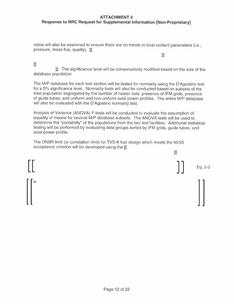
ratios will also be examined to ensure there are no trends in local coolant parameters (i.e., pressure, mass flux, quality). [[
]]
[[ ]]. The significance level will be conservatively modified based on the size of the
database population.
The M/P database for each test section will be tested for normality using the D'Agostino test for a 5% significance level. Normality tests will also be conducted based on subsets of the total population segregated by the number of heater rods, presence of IFM grids, presence of guide tubes, and uniform and non-uniform axial power profiles. The entire M/P database will also be evaluated with the D'Agostino normality test.
Analysis of Variance (ANOVA) F-tests will be conducted to evaluate the assumption of equality of means for several M/P database subsets. The ANOVA tests will be used to determine the "poolability" of the populations from the two test facilities. Additional statistical testing will be performed by evaluating data groups sorted by IFM grids, guide tubes, and axial power profile.
The DNBR limit (or correlation limit) for TVS-K fuel design which meets the 95/95 acceptance criterion will be developed using the [[
]]
[[ ]] w
Page 12 of 22
Eq. 2-2
ATTACHMENT 3 Response to NRC Request for Supplemental Information [Non-Proprietary]
In its letter dated July 19, 2018, the licensee states that the PRIME thermal mechanical computer code will be used to evaluate the thermal mechanical performance of the L TAs. The NRC has approved PRIME for use in evaluating the thermal mechanical performance for BWR fuel (Reference 2), but while the validation data set included PWR fuel, the NRC did not explicitly approve PRIME for PWR applications. The licensee discusses some of the PWR specific considerations documented by the NRC contractor that performed the review, but insufficient information is provided to confirm that PRIME is appropriately validated for PWR applications. For example, [[
]] Provide a discussion, including relevant data, regarding the validation for PWR applications, such that the NRC staff can confirm the acceptability of PRIME results for PWR specific applications. Discuss the applicability of the validation data to the materials specific to the LTAs.
Reference
2. Letter from A. A. Lingenfelter (GNF-A) to USN RC Document Control Desk, "Accepted Versions of Global Nuclear Fuel -Americas Topical Reports NEDC-33256P, 'The PRIME Model for Analysis of Fuel Rod Thermal - Mechanical Performance Part 1 Technical Bases,' NEDC-33257P, The PRIME Model for Analysis of Fuel Rod Thermal -Mechanical Performance Part 2 - Qualification,' and NEDC-33258P, 'The PRIME Model for Analysis of Fuel Rod Thermal-Mechanical Performance Part 3 - Application Methodology' (TAC# MD4114)," dated September 15, 2010, ADAMS Accession No. ML 102600259.
EGC Response to RSI 3
PRIME uses [[
]] are described below. [[
]], as noted in the Braidwood LAR dated July 19, 2018.
Page 13 of 22
ATTACHMENT 3 Response to NRC Request for Supplemental Information [Non-Proprietary]
Page 14 of 22
Density The density of E110opt cladding material has been measured at [[ room temperature using the hydrostatic weighing method ]]. The E110opt density is [[ similar to the Zirclaloy-2 value used in PRIME ]]. Metal density varies little with temperature within the same crystallographic phase and therefore the E110opt [[ room temperature measurement is applicable throughout the PRIME application range ]]1.The measured E110opt value will be used to model the TVS-K fuel. Thermal Expansion The coefficients of linear thermal expansion (CLTE) for E110opt cladding have been measured up to [[ 550°C (1022F) using dilatometry ]], which is above the PRIME application range. The E110opt CLTE is [[ similar to the Zircaloy-2 model used in PRIME ]]. The measured E110opt CLTE data was used to develop new coefficients for the Zircaloy-2 PRIME model. The Zircaloy-2 PRIME model with new coefficients will be used to model the TVS-K fuel. Specific Heat The specific heat capacity of E110opt has been measured up to [[ 1200C (2192F) using calorimetry ]]. The E110opt specific heat is [[ similar to the Zirclaloy-2 model used in
1 PRIME cladding temperature is limited to 400°C (752°F) for normal operation and 450°C (842°F) for slow transients.
ATTACHMENT 3 Response to NRC Request for Supplemental Information [Non-Proprietary]
]]. A new specific heat model fit to the E110opt data will be used to model the TVS-K fuel. PRIME cladding temperature is [[ ]] which is well below the [[
]] temperature.
Meyer Hardness
The Zircaloy-2 PRIME Meyer Hardness model is based on [[ ]]. The Zircaloy-2 PRIME Meyer Hardness model will be used to model the
TVS-K fuel using the [[ ]]. E11 Oopt [[ ]], which is above
the PRIME application range.
Thermal Conductivity
The thermal conductivity of E11 O has been measured up to [[ ]]. The composition difference between [[
]] thermal conductivity. The E11 O thermal conductivity is [[ ]]. A new thermal conductivity model fit to the E11 O
data will be used to model the TVS-K fuel.
Emissivity of Fuel Rod Inner Surface
The emissivity of E11 Oopt [[ like Zircaloy-2 and E11 Oopt [[ Zircaloy-2 PRIME [[
]]. Similar unoxidized zirconium alloys ]]. The
to model the TVS-K fuel.
Elastic (Young's) Modulus and Poisson's Ratio
Young's modulus and Poisson's ratio have been measured for E11 Oopt [[ ]]. Zirconium alloys [[
]] will be adopted
]], which introduces a small but reasonable uncertainty in the elastic constants. E11 Oopt Young's modulus and Poisson's ratio are [[
]]. TVS-K fuel will be modeled based on the measured values of E11 Oopt Young's modulus and Poisson's ratio [[ ]].
Stress-Strain Relations (UTS, YS, strain)
E11 O and E11 Oopt irradiated and unirradiated cladding ultimate tensile strength (UTS), yield strength (YS), and strain were measured [[ ]]. Results will be used to determine new coefficients for the Zircaloy-2 PRIME [[
]]. The model [[
]]. TVS-K fuel will be modeled using the Zircaloy-2 PRIME model with new coefficients.
Page 15 of 22
ATTACHMENT 3 Response to NRC Request for Supplemental Information [Non-Proprietary]
E11 O and E11 Oopt irradiated and unirradiated cladding creep strains were measured [[ ]]. Tests were conducted for [[
]]. Results were used to determine new coefficients for the [[ ]] PRIME application range. Model results [[
]]. TVS-K fuel will be modeled using the Zircaloy-2 PRIME model with new coefficients.
Fatigue
E11 O and E11 Oopt irradiated and unirradiated cladding fatigue limits were determined [[ ]]. Tests were conducted for [[
]] asymmetry coefficients. Results were used to determine [[
]].
Irradiation Growth
E11 O and E11 Oopt irradiation growth strains of coupons were measured [[ ]]. Tests were conducted for [[
]] Irradiation growth of E11 Oopt is [[
]]. TVS-K fuel will be modeled using the Zircaloy-2 PRIME model with new coefficients.
Corrosion Film Thermal Conductivity
Experimental data for 11 Oopt corrosion film (zirconium oxide) thermal conductivity is [[
Page 16 of 22
]]
ATTACHMENT 3 Response to NRC Request for Supplemental Information [Non-Proprietary]
Corrosion
The corrosion performance of E11 O and E11 Oopt has been evaluated by [[
]]. Tests and irradiation experience are in water chemistry environments that include [[
]]. Irradiation experience extends to [[ ]]. The experimental data was used to determine new
coefficients for the Zircaloy-2 PRIME model. The TVS-K fuel will be modeled using the Zircaloy-2 PRIME model with new coefficients.
Crud Deposition
[[ Experimental data for in-service crud deposition on TVS-K fuel is [[ BWR PRIME crud deposition model [[
modeled based on the [[
]]
Crud Thermal Conductivity
]]. The
]]. TVS-K fuel will be
Experimental data for the thermal conductivity of crud deposited in-service on TVS-K fuel is [[ ]]. TVS-K fuel will be modeled using the [[
]]
PRIME Application Ranges Relevant to Fuel Properties
The range of applicability of individual fuel performance models is governed by the extent of the PRIME qualification database. As part of its review of the calibration and validation of individual fuel performance models, the NRC assessed the range of applicability. The PRIME03 database, which includes [[
]] required for TVS-K fuel material. The [[
]] data comparisons.
GNF BWR U02 and (U,Gd)02 fuel pellet material properties [[ ]] TVS-K Braidwood LT A fuel. The application range of these pellet properties for
[[ ]]. Each of these
parameters is discussed below.
LHGR PRIME steady state LHGR application range is [[
]]. The TVS-K fuel steady-state LHGR will be [[ ]].
Page 17 of 22
ATTACHMENT 3 Response to NRC Request for Supplemental Information [Non-Proprietary]
Exposure PRIME peak pellet exposure application range is [[ ]], which as documented in the Safety Evaluation Report for PRIME (Reference 3-2), corresponds to a [[ ]]. The TVS-K LT A fuel will be [[ ]] exposure.
Temperature PRIME fuel temperature application range is [[ The fuel melting temperature is [[ TVS-K fuel temperatures will be [[
Density
]] PWR operating conditions. The ]].
PRIME pellet density application range, supported by its validation database, is [[ ]] theoretical density. The U02 pellets used in the TVS-K L TAs have nominal
theoretical density of [[ ]], so this is well within the PRIME application range.
Grain Size
]].
PRIME initial pellet 30 grain size is limited to a [[ U02 pellets will have initial 30 grain size that is [[ (U,Gd)02 LTA pellets will be [[
]]. The TVS-K LT A ]]. Both U02 and
]].
References for Response to RSI 3
3-1 Luscher W .G., and. Porter I.A., "Material Property Correlations: Comparisons between FRAPCON-4.0, FRAPTRAN 2.0, and MATPRO," Revision 2, PNNL-19417, Pacific Northwest National Laboratory, Richland, WA, 2015 (https ://frapcon . labworks.org/Code-documents/Material_Property _Correlations. pdf)
3-2 Letter from T. B. Blount (NRC) to Mr. A. A. Lingenfelter (GNF-A), "Final Safety Evaluation for Global Nuclear Fuel - Americas Topical Reports NEDC-33256P, NEDC-33257P, NEDC-33258P, 'The PRIME Model for Analysis of Fuel Rod Thermal-Mechanical Performance' (TAC NO. MD4114)," dated January 22, 2010, ADAMS Accession Nos. ML 100190258 (transmittal letter) ; ML 100150653 (SE); and ML 100150681 (Attachment to SE).
Page 18 of 22
ATTACHMENT 3 Response to NRC Request for Supplemental Information [Non-Proprietary]
RSI 4
Compliance with 1 O CFR 50.46 and GDC 10 requirements as well as GDC 2, "Design bases for protection against natural phenomena," is typically demonstrated by showing that postulated seismic and loss-of-coolant accident (LOCA) events will not result in deformation that challenges coolability.
In its letter dated July 19, 2018, the licensee states that the current approved AOR methods will be used to evaluate the seismic and LOCA loads, with the L TAs explicitly modeled using test-based dynamic information. The current licensing basis for Braidwood Station is based on Westinghouse analytic methodologies, which include both testing and analytical methodologies. The licensee does not provide further information regarding the testing performed for the (non-Westinghouse) L TA design, and how the L TAs are compatible with the analytical methodologies used to analyze the seismic and LOCA loads.
The NRG staff requests the following information in order to complete its detailed review:
Provide a description of the testing performed to determine the relevant parameters used to model the L TAs in the AOR methods for seismic/LOCA events at Braidwood Station, and discuss why the testing is consistent with the analytical methodology.
EGG Response to RSI 4
As stated in the original TVS-K lead test assembly Licensing Amendment Request (Reference 4-1) the seismic and LOCA loads are provided by Westinghouse Electric Company (WEC) via the analysis of record (AOR) methodology. These loads are then used to evaluate the component strengths. To achieve this, WEC defined via formal Design Input Request (DIR), the dynamic parameters that are required to support the analysis.
Technical discussions were held between the analysis provider (WEC), the fuel designer (TVEL), the fuel US licenser (GNF) , and the licensee (Exelon) to ensure that that the parameters were defined and understood. To support this, WEC provided the basis for the analytical model in conjunction with how the paraments were applied in the model. Furthermore, the method by which the parameter values had been obtained by the fuel designer were discussed to ensure that they would be adequate for the model application. The parameter definitions contained in the DIR were modified to reflect the conclusion of the technical discussions.
[[
]]
These parameters were required by WEC to create a dynamic model of the non-Westinghouse fuel design (TVS-K LT A) that could be used conjunction with the co-resident
Page 19 of 22
ATTACHMENT 3 Response to NRC Request for Supplemental Information [Non-Proprietary]
fuel. The parameters provide the basis for the dynamic movement of the TVS-K LT As with the co-resident fuel and are consistent with the co-resident fuel basis. This model is used to simulate the interaction with the co-resident fuel and provides bounding loads for the evaluation of the relevant structural components.
The dynamic parameters that are required to model the fuel are generated by a combination of test and analysis of the TVS-K design. All TVEL testing was completed by qualified personnel, following approved testing procedures. Test equipment is defined and controlled, and all necessary instrumentation is calibrated to recognizable standards. Testing output is documented, and configuration is controlled.
The testing that was completed to establish the parameters falls broadly into three areas of testing:
• Component testing - completed to establish specific parameters directly via testing • Assembly testing - completed to simulate complex mechanical interactions that are
not practical to model • Benchmark testing - completed to confirm specific analytic basis
Component Testing - Grid Crush Component testing was completed to confirm specific mechanical properties of the fuel components. The scope of the testing for the spacer grid determined buckling loads of the fuel assembly during a loss-of-coolant (LOCA) plus safe shutdown earthquake (SSE) accident.
The testing was completed using a calibrated universal testing machine that can apply and measure forces with high accuracy. End of life conditions were simulated by cell loosening (relaxation) and grid heating in a heat chamber. [[
]]
The universal test machine was configured to provide instantaneous automatic removal of applied load when plastic deformations appeared in the spacer grid.
Upon plastic deformation and cessation of loading, the spacer grids were visually inspected. Minor deformations of the faces and peripheral cells in the direction of impact load were observed. The spacer grid geometrical dimensions between the guide thimble fragments were observed to be unchanged along with the guide thimble internal diameters. The spacer grid deformation demonstrated negligible local flow area restriction. The spacer grid central region had no significant deformations that would impact the insertion of the rod cluster control assembly (RCCA).
Assembly Testing - Lateral Stiffness A set of mechanical tests of a full-scale mock-up fuel assembly manufactured by the fuel production facility was performed on a full-scale test stand designed specifically for complex mechanical tests of the fuel assembly. Part of this test scope was completed to determine the fuel assembly lateral stiffness. The test stand configuration included representative fastening of the bottom and top nozzles that simulates the operating configuration in a PWR reactor.
Page 20 of 22
ATTACHMENT 3 Response to NRC Request for Supplemental Information [Non-Proprietary]
The lateral stiffness of the fuel assembly was determined using linear displacement transducers with the measurements recorded by a universal measuring system provided by the sensor manufacturer. Simulated compression forces (axial) on the fuel assembly were applied followed by incremental transverse loads, deflecting the fuel assembly. [[
]]
Benchmark Testing - Natural Frequency This test was used to benchmark values that were established analytically using finite element analysis. To benchmark the natural frequency, oscillation measurements were taken using a full-scale mock-up fuel assembly that was manufactured per the standard process in the fuel production facility.
[[
]]
References for Response to RSI 4
4-1 Letter from D. M. Gullott (Exelon Generation Company, LLC) to U.S. Nuclear Regulatory Commission, "License Amendment Request to Utilize TVEL TVS-K Lead Test Assemblies," dated July 19, 2018 (ADAMS accession No. ML 18204A 169)
Page 21 of 22
ATTACHMENT 3 Response to NRC Request for Supplemental Information [Non-Proprietary]
In its letter dated July 19, 2018, the licensee states that a source term specific to the TVS-K L TAs will be used to evaluate changes to the current source term due to the higher uranium loading and lower power density of the TVS-K LT As. 1 O CFR 50.67 (b)(2) requires that the licensee's accident source term analysis must demonstrate with reasonable assurance that the criteria in 1 O CFR 50.67 (b)(2)(i), (ii), and (iii) are met. Regulatory Guide 1.183, "Alternative Radiological Source Terms for Evaluating Design Basis Accidents at Nuclear Power Reactors," dated July 2000 (ADAMS Accession No. ML003716792), Section 1.3.2, "Re-Analysis Guidance," states that the evaluation should consider the impact of modifications to compliance with the regulatory criteria. The information provided by the licensee does not demonstrate that the regulatory criteria will be met.
Provide a source term specific to the TVS-K LT As that "would be used to evaluate changes to the current source term due to the higher uranium loading and lower power density of the TVS-K L TAs." Regulatory Guide 1.183 states that a complete recalculation of all facility radiological analyses is not expected, but all impacts of the proposed changes should be evaluated.
EGC Response to RSI 5
The fuel assembly uranium mass for the TVS-K L TA is approximately 11 % heavier than the resident Westinghouse fuel assembly uranium mass. Impact on the total isotopic inventory of the core is negligible because the L TAs comprise only 4.1 % of the core (eight L TAs out of a total core of 193 assemblies). A peaking factor of 1.7 is used in the current fuel handling accident dose analysis. As stated in the LAR, the L TA is required to maintain at least 5% peaking factor margin to the lead Westinghouse fuel assembly. The peaking factor reduction is sufficient to offset the impact of higher uranium mass; therefore, the current analysis is bounding for the L TAs. This evaluation and impacts will be documented against Braidwood Station radiological analyses of record.
Page 22 of 22