Embed Size (px)
Citation preview

2790 Indian Ripple Road • Russ Research Center • Dayton, Ohio • 45440
(937) 320-5999 • (937) 320-7773 • [email protected] • www.spectra-research.com
Proprietary Proprietary -- Competition SensitiveCompetition Sensitive
Fragmented Volume AntennasFragmented Volume AntennasTechnology OverviewTechnology Overview
SBIR RFI – AF071-357Presented to:Larry LeDuc
Presented by:Daniel D. Reuster, Ph.D
& Jeff [email protected]
937.320.5999x28
30 November 2006

30NOV06
Page 2 of 29
PROPRIETARY
OverviewOverview
• Small, woman-owned business founded in 1989• Staff of multi-disciplined engineers and scientists• Wide array of technology thrusts
– Advanced antennas, RFID, EO/IR, and software modeling/simulation
• Over 100 development programs – 7 US patents• Various EM Numerical Analysis / CAD Packages• Rapid Prototyping Capability (PCB, plastic, light metals)

PROPRIETARY 30OCT06
Ongoing ProgramsOngoing ProgramsRadio Frequency Identification (RFID)Radio Frequency Identification (RFID)
• Combat Identification Tags
- Air-to-Ground CID
- Ground-to-Ground CID
- X, Ku, Ka bands
• Asset Tracking
Advanced AntennasAdvanced Antennas• Miniaturized GPS
• Multi-band ESM
• Electronically scanned arrays
• Non-invasive medical imaging
X-band layer
Ku-band layerKa-band layer
EO / IR Technologies EO / IR Technologies • Non-intrusive traffic monitoring
• Pavement profiler
• Flash Ladar Processing
• Laser threat warning system
• IED detection system
• CW Laser identification system
Advanced Training SystemsAdvanced Training Systems• Non-pyrotechnic Cueing Device
CEM Modeling / Rapid PrototypingCEM Modeling / Rapid Prototyping• IV & V• CAD / CAM / Solid modeling

30NOV06
Page 4 of 29
PROPRIETARY
Fragmented Aperture Tech.Fragmented Aperture Tech.
10” x 10” Antenna Broadside Radiation
• Gain > 5 dB over the frequency range of optimization• Good agreement with experimental measurements• This design has ~3 dB more gain than Archimedean spiral
Feed
0 1 2 3 4
Bro
adsi
de G
ain,
dB
-5
0
5
10
15FDTD ModelMeasuredAperture Gain Spiral Antenna
OptimizationRange
Optimized 0.8 - 2.5 GHz

30NOV06
Page 5 of 29
PROPRIETARY
Fragmented Aperture Cont.Fragmented Aperture Cont.
Choose aperture
basis
Create initial population of
antennasEvaluate and rank
each antenna design
Rank based on pre-defined criteria (e.g. realized gain)(2), (3)
Create next generation of candidates
Success!-30
-25
-20
-15
-10
-5
0
5
10
105321.5.3
Rea
lized
Gai
n (d
B)
Frequency (GHz)
Area GainFar Field V-Pol
Anech. Chmbr H-PolAnech. Chmbr V-pol
Compact RangeNumerical Prediction
Goal met?
Successful design requires(1) Wise choice of aperture basis - brute force doesn’t
work – no convergence(2) Fast, accurate computation engine (UWAA-funded
software enhancements); 100’s of parallel cpu’s (3) Careful definition of optimizer cost function
Successful design requires(1) Wise choice of aperture basis - brute force doesn’t
work – no convergence(2) Fast, accurate computation engine (UWAA-funded
software enhancements); 100’s of parallel cpu’s (3) Careful definition of optimizer cost function
Beowulf Clusters
GTRI Patent (US# 6,323,809 )
Choose wisely – use antenna insights (1)
Generate 100’s of random candidates
Use genetic algorithm to create (better) antennas

30NOV06
Page 6 of 29
PROPRIETARY
GPS Antenna ExampleGPS Antenna Example
• Element designed with a “wideband feed”
• This results in more bandwidth for a given element sizeWideband feed

30NOV06
Page 7 of 29
PROPRIETARY
Numerical and Virtual ModelingNumerical and Virtual Modeling
From Numerical Modeling
Direct to CAM Machining

30NOV06
Page 8 of 29
PROPRIETARY
Fabricated Fabricated -- 2 inch Element2 inch Element
Frequency (GHz)
S11 (dB)
PredictedMeasured
S11 Comparison

30NOV06
Page 9 of 29
PROPRIETARY
MetaMeta--MaterialMaterial
• ARLON AD600 Commercial Meta-Material– DK 6.3-j0.4: 0.125” thickness: 1oz Cu

30NOV06
Page 10 of 29
PROPRIETARY
ApproachApproach
• Utilize 3D FragmentedAperture Antennas– Fragmented apertures
antennas were developed to best utilize available planar area
– 3D fragmented apertures(fragment volumes) bestutilize available volume

30NOV06
Page 11 of 29
PROPRIETARY
Exploratory GeometryExploratory Geometry
50 ohmCoax Feed
10” x10” x 10”quadrant
Symmetricalremainingquadrants
GroundPlane
y
z

30NOV06
Page 12 of 29
PROPRIETARY
Exploratory GeometryExploratory Geometry
• 3D AutocadDXF view of representative quadrant
• Ground plane is not shown
• Symmetrical quadrants not shown
10x10x10 Quadrant
¼ of antenna shown (two planes of symmetry)Monopole
Feed (50ohm)
1 inch wiresegments

30NOV06
Page 13 of 29
PROPRIETARY
Case 5: 100Case 5: 100--400 MHz400 MHz
0 0.1 0.2 0.3 0.4 0.50
0.2
0.4
0.6
0.8
1
frequency (GHz)
refle
ctio
n co
ef (m
ag)
case5: 10x10x10, 1 inch wire, 100-400 MHz
0 0.1 0.2 0.3 0.4 0.5-10
-5
0
5
10
frequency (GHz)
real
ized
gai
n (d
BiL
)
case5: 10x10x10, 1 inch wire, 100-400 MHz
• 4:1 bandwidth achievable • Electrical size of antenna at upper end of band can cause pattern changes
30NOV06
Page 14 of 29
PROPRIETARY
Use of Lumped ElementsUse of Lumped Elements
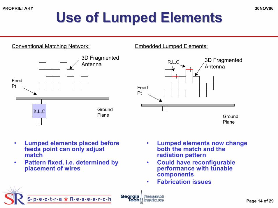
Conventional Matching Network: Embedded Lumped Elements:
• Lumped elements placed before feeds point can only adjust match
• Pattern fixed, i.e. determined by placement of wires
3D FragmentedAntenna R,L,C
R,L,C GroundPlane
Feed Pt
3D FragmentedAntenna
Feed Pt
GroundPlane
• Lumped elements now change both the match and the radiation pattern
• Could have reconfigurable performance with tunable components
• Fabrication issues

30NOV06
Page 15 of 29
PROPRIETARY
Use of Lumped Elements (Cont)Use of Lumped Elements (Cont)
Multiple ports: Multiple ports, multiple functions
• Lumped elements placed on secondary feed points change both the match and radiation pattern
• Easy to fabricate (wires all metal)• Potentially easier to tune
components if reconfigurable desired
3D FragmentedAntenna
GroundPlane
Feed Pt
3D FragmentedAntenna
GroundPlane
Feed Pt
R,L,CFilter1 Filter2
• Each port supports separate function
• RF filters achieve band splitting and secondary port reactance for matching
• Extendable beyond two ports

30NOV06
Page 16 of 29
PROPRIETARY
Reduced, TwoReduced, Two--Port GeometryPort Geometry
• Reduce volume of antenna by 50%
• Add second port
• Initially consider loaded port 2 configurationsPort 1: 50 ohm
Coax Feed
10x10x10quadrant
Symmetricalabout
GroundPlane
Port 2: 50 ohmCoax Feed
y
z
30NOV06
Page 17 of 29
PROPRIETARY
Case 6: TwoCase 6: Two--Port, 100Port, 100--400 MHz400 MHz
0 0.1 0.2 0.3 0.4 0.5-10
-5
0
5
10
frequency (GHz)re
aliz
ed g
ain
(dB
iL)
case6: 10x10x10, 1 inch wire, 100-400 MHz
0 0.1 0.2 0.3 0.4 0.50
0.2
0.4
0.6
0.8
1
frequency (GHz)
refle
ctio
n co
ef (m
ag)
case6: 10x10x10, 1 inch wire, 100-400 MHz
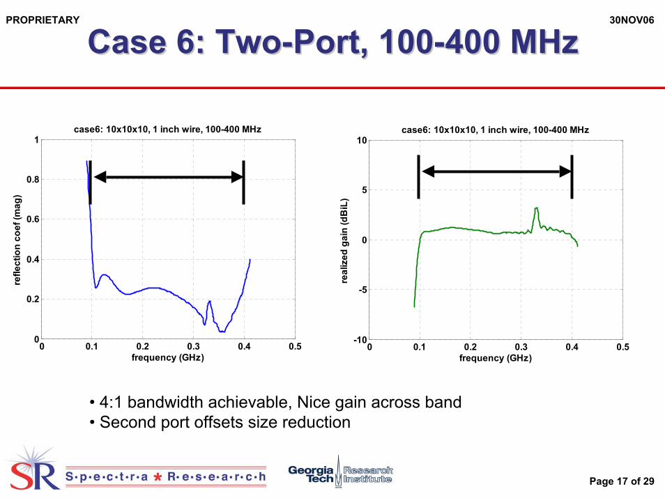
• 4:1 bandwidth achievable, Nice gain across band• Second port offsets size reduction

30NOV06
Page 18 of 29
PROPRIETARY
Reactive MultiReactive Multi--port demonstrationport demonstration
• Reduced volume of antenna by total of 80% from initial size
• Second port now reactive termination
Port 1: 50 ohmCoax Feed
6x8x8quadrant
Symmetricalabout
GroundPlane
Port 2: 50 ohmCoax Feed
y
z
30NOV06
Page 19 of 29
PROPRIETARY
Reactive MultiReactive Multi--port Demonstrationport Demonstration
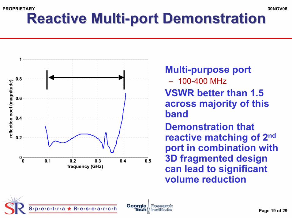
• Multi-purpose port– 100-400 MHz
• VSWR better than 1.5 across majority of this band
• Demonstration that reactive matching of 2nd
port in combination with 3D fragmented design can lead to significant volume reduction
0 0.1 0.2 0.3 0.4 0.50
0.2
0.4
0.6
0.8
1
frequency (GHz)
refle
ctio
n co
ef (m
agni
tude
)

30NOV06
Page 20 of 29
PROPRIETARY
3D Fragmented Antenna Fabrication Process3D Fragmented Antenna Fabrication Process
Use stereo-lithography (SLA)and/or selective lasersintering (SLS) Machinesto make 3D part
Experimental workHas consideredvarious coating options
Optional insertion of high index materials(e.g. dielectrics) intokey areas of 3D structure
Significant weight savings
Final part includes3D antenna structureand placed highindex materials

30NOV06
Page 21 of 29
PROPRIETARY
MultiMulti--Purpose Antenna Purpose Antenna VV--PolPol OmniOmni--Directional Antenna (30Directional Antenna (30--450 MHz)450 MHz)
x
z
y8”
2”
4”
16”
9”
1”
Female N-FeedConnector
1 inch “Fragmented”Wire Mesh Structure
• 4” x 16” x 9” antenna structure
• Two degrees of symmetry– xz plane– yz plane
• Single Female N-Feed connector
• Dk=10 ceramic volume• 3D “Fragmented” wire
mesh design

30NOV06
Page 22 of 29
PROPRIETARY
Mesh DesignMesh Design
• Within each of the four symmetric regions, a wire mesh structure is generated using a genetic algorithm.
• The wire directions are constrained to the x, y and z axes.
x
z
y8”
2”
4”
16”
9”
Female N-FeedConnector
1 inch “Fragmented”Wire Mesh Structure

30NOV06
Page 23 of 29
PROPRIETARY
Genetic CodeGenetic Code
• Each cell contains three wire segments– x, y, z
• They are represented by a 3-bit binary number
• The binary numbers are concatenated together to form the genetic code for the antenna– 111011101110100010000001
x
y
z111
x
y
z011
x
y
z101
x
y
z110
x
y
z100
x
y
z010
x
y
z001
x
y
z000

30NOV06
Page 24 of 29
PROPRIETARY Sub MaskingSub MaskingBoundary Condition ImplementationBoundary Condition Implementation
x
y
y-face boundary condition 101
upper boundary condition 110lower boundary condition 001 x-face boundary condition 011
corner boundary condition 001
• The antenna design volume is terminated by five boundary regions:– upper, lower, x-face, y-face & corner
• These boundary conditions are logical “ANDed”to the genetic code to provide a smooth boundary.
Page 25 of 29
PROPRIETARY
Design FabricationDesign Fabrication
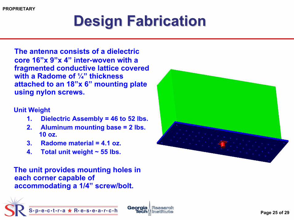
The antenna consists of a dielectric core 16”x 9”x 4” inter-woven with a fragmented conductive lattice covered with a Radome of ¼” thickness attached to an 18”x 6” mounting plate using nylon screws.
Unit Weight1. Dielectric Assembly = 46 to 52 lbs.2. Aluminum mounting base = 2 lbs.
10 oz.3. Radome material = 4.1 oz.4. Total unit weight ~ 55 lbs.
The unit provides mounting holes in each corner capable of accommodating a 1/4” screw/bolt.

Page 26 of 29
PROPRIETARY
Fabrication (Cont.)Fabrication (Cont.)
Once an antenna design has been finalized it will be converted into a 3-D model using AutoCAD.
The dielectric substrate will be fabricated using 8 segments of 8”x9”x1” C-STOCK ceramic filled plastic.
Clearance for the conductive lattice will be cut into each individual piece using a 3-D milling machine.

Page 27 of 29
PROPRIETARY
Fabrication (3)Fabrication (3)
Once all pieces are cut, the two pieces that make up the first layer will be bonded together (Step 1). The conductive lattice will then be build-up using 3/16” brass tubing soldered together at all joints (Step 2).
Page 28 of 29
PROPRIETARY
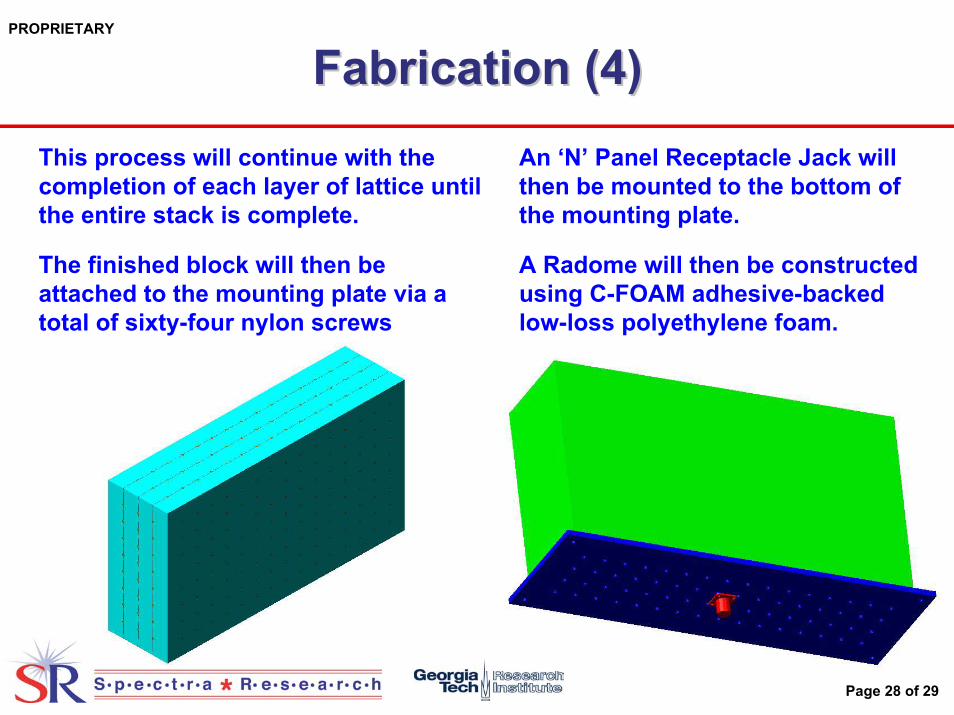
Fabrication (4)Fabrication (4)This process will continue with the completion of each layer of lattice until the entire stack is complete.
The finished block will then be attached to the mounting plate via a total of sixty-four nylon screws
An ‘N’ Panel Receptacle Jack will then be mounted to the bottom of the mounting plate.
A Radome will then be constructed using C-FOAM adhesive-backed low-loss polyethylene foam.
30NOV06
Page 29 of 29
PROPRIETARY
AF071AF071--357 Requirements357 Requirements
• 100-300 MHz Frequency Band• 20 dBi Antenna Gain / 30 deg. Beam Width• 10’ x 10’ x 10’ Volume Constraint• 300 lbs Weight Requirement• Dual Feed V-Pol and H-Pol• Mount on EX105/10-2.3 from Mastsystems• VSWR < 2 (1.5 if possible)• Traditional Antenna Design would require
40’ x 40’ x 40’ Volume Constraint
![FDTD on Distributed Heterogeneous Multi-GPU Systemssimulations using FDTD, as shown in the article: CUDA Based FDTD Implementation [6]. The goal of this thesis is to develop a solution](https://img.pdfslide.us/doc/110x75/610471a4a4cc2b14047b4d0c/fdtd-on-distributed-heterogeneous-multi-gpu-systems-simulations-using-fdtd-as-shown.jpg)