Embed Size (px)
DESCRIPTION
Steel plan refractories
Citation preview
3.1 Classification of Refractories
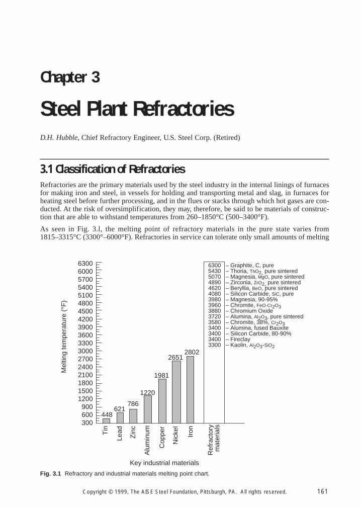
Refractories are the primary materials used by the steel industry in the internal linings of furnacesfor making iron and steel, in vessels for holding and transporting metal and slag, in furnaces forheating steel before further processing, and in the flues or stacks through which hot gases are con-ducted. At the risk of oversimplification, they may, therefore, be said to be materials of construc-tion that are able to withstand temperatures from 260–1850°C (500–3400°F).
As seen in Fig. 3.l, the melting point of refractory materials in the pure state varies from1815–3315°C (3300°–6000°F). Refractories in service can tolerate only small amounts of melting
Chapter 3
Steel Plant RefractoriesD.H. Hubble, Chief Refractory Engineer, U.S. Steel Corp. (Retired)
Copyright © 1999, The AISE Steel Foundation, Pittsburgh, PA. All rights reserved. 161
6300 – Graphite, C, pure5430 – Thoria, ThO2, pure sintered5070 – Magnesia, MgO, pure sintered4890 – Zirconia, ZrO2, pure sintered4620 – Beryllia, BeO, pure sintered4080 – Silicon Carbide, SiC, pure3980 – Magnesia, 90-95%3960 – Chromite, FeO-Cr2O33880 – Chromium Oxide3720 – Alumina, Al2O3, pure sintered3580 – Chromite, 38%, Cr2O33400 – Alumina, fused Bauxite3400 – Silicon Carbide, 80-90%3400 – Fireclay3300 – Kaolin, Al2O3-SiO2
630060005700540051004800450042003900360033003000270024002100180015001200900600300
Tin
Lead
Zin
c
Alu
min
um
Cop
per
Nic
kel
Iron
Key industrial materials
Mel
ting
tem
pera
ture
(°F
)
448621
786
1220
1981
26512802
Ref
ract
ory
mat
eria
ls
Fig. 3.1 Refractory and industrial materials melting point chart.
Ironmaking Volume
162 Copyright © 1999, The AISE Steel Foundation, Pittsburgh, PA. All rights reserved.
(1–5%) without loss of their important structural characteristics. Subsequent discussion will show,however, that the use of many such materials is limited by factors such as cost or instability in cer-tain atmospheres. Also, fluxes present in the initial impure refractory and/or encountered in ser-vice can seriously reduce these melting points.
Refractories are expensive, and any failure in the refractories results in a great loss of productiontime, equipment, and sometimes the product itself. The type of refractories also will influenceenergy consumption and product quality. Therefore, the problem of obtaining refractories bestsuited to each application is of supreme importance. Economics greatly influence these problems,and the refractory best suited for an application is not necessarily the one that lasts the longest, butrather the one which provides the best balance between initial installed cost and service perfor-mance. This balance is never fixed, but is constantly shifting as a result of the introduction of newprocesses or new types of refractories. History reveals that refractory developments have occurredlargely as the result of the pressure for improvement caused by the persistent search for superiormetallurgical processes. The rapidity with which these ever recurring refractory problems havebeen solved has been a large factor in the rate of advancement of the iron and steel industry. To dis-cuss the many factors involved in these problems and to provide information helpful to their solu-tion are the objectives of this chapter.
Refractories are also vital in the safe operation of the processes and must not expose personnel to haz-ardous conditions during their manufacture, installation, use or during disposal following their use.
Refractories may be classified in a number of ways. From the chemical standpoint, refractory sub-stances, in common with matter in general, are of three classes; namely, acid, basic, and neutral.Theoretically, acid refractories should not be used in contact with basic slags, gases or fumeswhereas basic refractories can be best used in contact with a basic chemical environment. Actually,for various reasons, these rules are often violated. Hence, the time honored chemical classificationis largely academic, and of little value as a guide to actual application. Also, the existence of a trulyneutral refractory may be doubted. Classifications by use, such as blast furnace refractories orrefractories for oxygen steelmaking, are generally too broad and are constantly subject to revision.
For our purposes, refractories will be classified with reference to the raw materials used in theirpreparation and to the minerals predominating after processing for use. This classification isbelieved to offer the best possibility for a clear understanding of the origin and nature of steel plantrefractories.
3.1.1 Magnesia or Magnesia–Lime Group
This group includes all refractories made from synthetic magnesites and dolomite. These consti-tute the most important group of refractories for the basic steelmaking processes. All these mate-rials are used primarily as a source of magnesia (MgO).
3.1.1.1 Magnesia
Modern high-purity magnesias are produced in well controlled processes. The principal sources ofmagnesias are brines (often deep well type) and seawater. Magnesium hydroxide, Mg(OH)2, is pre-cipitated from these sources by reaction with calcined dolomite or limestone; one source uses a novelreactor process. The resultant magnesium hydroxide slurry is filtered to increase its solids content.The filter cake can then be fed directly to a rotary kiln to produce refractory grade magnesia, butmore commonly now the filter cake is calcined at about 900–1000°C (1650 –1830°F), usually in mul-tiple-hearth furnaces, to convert the magnesium hydroxide to active magnesia. This calcined magne-sia is then briquetted or pelletized for firing into dense refractory-grade magnesia, usually in shaftkilns which reach temperatures around 2000°C (3630°F). The end product is sintered magnesia.
Fused magnesia is produced by melting a refractory grade magnesia or other magnesia precursorin an electric arc furnace. The molten mass is then removed from the furnace, cooled, and brokenup to begin its path for use in refractories.
Steel Plant Refractories
Copyright © 1999, The AISE Steel Foundation, Pittsburgh, PA. All rights reserved. 163
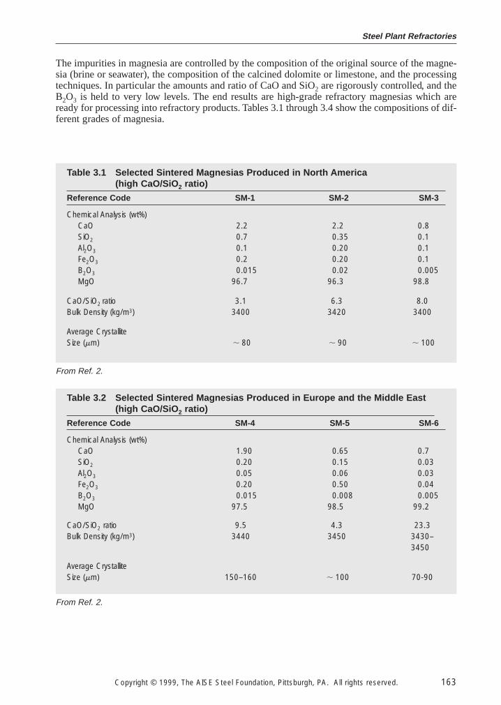
The impurities in magnesia are controlled by the composition of the original source of the magne-sia (brine or seawater), the composition of the calcined dolomite or limestone, and the processingtechniques. In particular the amounts and ratio of CaO and SiO2 are rigorously controlled, and theB2O3 is held to very low levels. The end results are high-grade refractory magnesias which areready for processing into refractory products. Tables 3.1 through 3.4 show the compositions of dif-ferent grades of magnesia.
Table 3.1 Selected Sintered Magnesias Produced in North America (high CaO/SiO 2 ratio)
Reference Code SM-1 SM-2 SM-3
Chemical Analysis (wt%)CaO 2.2 2.2 0.8SiO2 0.7 0.35 0.1Al2O3 0.1 0.20 0.1Fe2O3 0.2 0.20 0.1B2O3 0.015 0.02 0.005MgO 96.7 96.3 98.8
CaO/SiO2 ratio 3.1 6.3 8.0Bulk Density (kg/m3) 3400 3420 3400
Average CrystalliteSize (mm) , 80 , 90 , 100
Table 3.2 Selected Sintered Magnesias Produced in Europe and the Middle East(high CaO/SiO 2 ratio)
Reference Code SM-4 SM-5 SM-6
Chemical Analysis (wt%)CaO 1.90 0.65 0.7SiO2 0.20 0.15 0.03Al2O3 0.05 0.06 0.03Fe2O3 0.20 0.50 0.04B2O3 0.015 0.008 0.005MgO 97.5 98.5 99.2
CaO/SiO2 ratio 9.5 4.3 23.3Bulk Density (kg/m3) 3440 3450 3430–
3450
Average CrystalliteSize (mm) 150–160 , 100 70-90
From Ref. 2.
From Ref. 2.
Ironmaking Volume
164 Copyright © 1999, The AISE Steel Foundation, Pittsburgh, PA. All rights reserved.
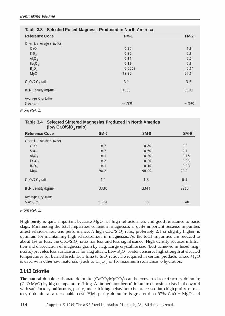
High purity is quite important because MgO has high refractoriness and good resistance to basicslags. Minimizing the total impurities content in magnesias is quite important because impuritiesaffect refractoriness and performance. A high CaO/SiO2 ratio, preferably 2:1 or slightly higher, isoptimum for maintaining high refractoriness in magnesias. As the total impurities are reduced toabout 1% or less, the CaO/SiO2 ratio has less and less significance. High density reduces infiltra-tion and dissociation of magnesia grain by slag. Large crystallite size (best achieved in fused mag-nesias) provides less surface area for slag attack. Low B2O3 content ensures high strength at elevatedtemperatures for burned brick. Low lime to SiO2 ratios are required in certain products where MgOis used with other raw materials (such as Cr2O3) or for maximum resistance to hydration.
3.1.1.2 Dolomite
The natural double carbonate dolomite (CaCO3•MgCO3) can be converted to refractory dolomite
(CaO•MgO) by high temperature firing. A limited number of dolomite deposits exists in the worldwith satisfactory uniformity, purity, and calcining behavior to be processed into high purity, refrac-tory dolomite at a reasonable cost. High purity dolomite is greater than 97% CaO + MgO and
Table 3.3 Selected Fused Magnesia Produced in North America
Reference Code FM-1 FM-2
Chemical Analysis (wt%)CaO 0.95 1.8SiO2 0.30 0.5Al2O3 0.11 0.2Fe2O3 0.16 0.5B2O3 0.0025 0.01MgO 98.50 97.0
CaO/SiO2 ratio 3.2 3.6
Bulk Density (kg/m3) 3530 3500
Average CrystalliteSize (mm) , 780 , 800
Table 3.4 Selected Sintered Magnesias Produced in North America (low CaO/SiO 2 ratio)
Reference Code SM-7 SM-8 SM-9
Chemical Analysis (wt%)CaO 0.7 0.80 0.9SiO2 0.7 0.60 2.1Al2O3 0.1 0.20 0.15Fe2O3 0.2 0.20 0.35B2O3 0.1 0.10 0.23MgO 98.2 98.05 96.2
CaO/SiO2 ratio 1.0 1.3 0.4
Bulk Density (kg/m3) 3330 3340 3260
Average CrystalliteSize (mm) 50-60 , 60 , 40
From Ref. 2.
From Ref. 2.
Steel Plant Refractories
Copyright © 1999, The AISE Steel Foundation, Pittsburgh, PA. All rights reserved. 165
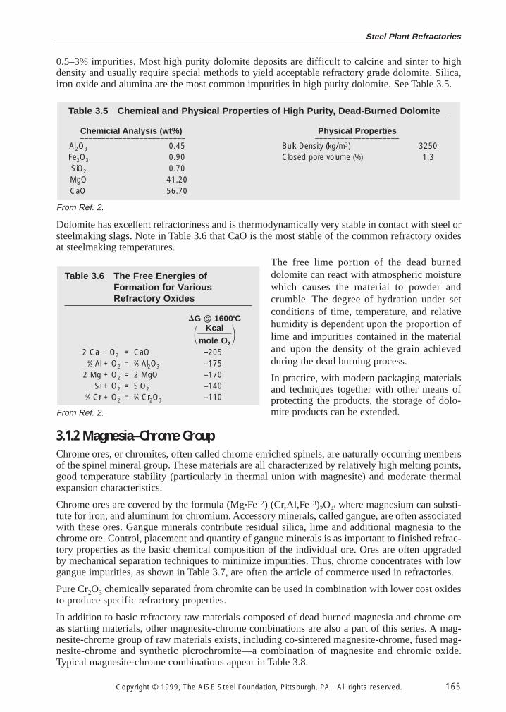
0.5–3% impurities. Most high purity dolomite deposits are difficult to calcine and sinter to highdensity and usually require special methods to yield acceptable refractory grade dolomite. Silica,iron oxide and alumina are the most common impurities in high purity dolomite. See Table 3.5.
Dolomite has excellent refractoriness and is thermodynamically very stable in contact with steel orsteelmaking slags. Note in Table 3.6 that CaO is the most stable of the common refractory oxidesat steelmaking temperatures.
The free lime portion of the dead burneddolomite can react with atmospheric moisturewhich causes the material to powder andcrumble. The degree of hydration under setconditions of time, temperature, and relativehumidity is dependent upon the proportion oflime and impurities contained in the materialand upon the density of the grain achievedduring the dead burning process.
In practice, with modern packaging materialsand techniques together with other means ofprotecting the products, the storage of dolo-mite products can be extended.
3.1.2 Magnesia–Chrome Group
Chrome ores, or chromites, often called chrome enriched spinels, are naturally occurring membersof the spinel mineral group. These materials are all characterized by relatively high melting points,good temperature stability (particularly in thermal union with magnesite) and moderate thermalexpansion characteristics.
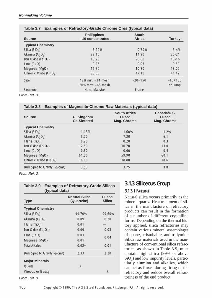
Chrome ores are covered by the formula (Mg•Fe+2) (Cr,Al,Fe+3)2O4′ where magnesium can substi-tute for iron, and aluminum for chromium. Accessory minerals, called gangue, are often associatedwith these ores. Gangue minerals contribute residual silica, lime and additional magnesia to thechrome ore. Control, placement and quantity of gangue minerals is as important to finished refrac-tory properties as the basic chemical composition of the individual ore. Ores are often upgradedby mechanical separation techniques to minimize impurities. Thus, chrome concentrates with lowgangue impurities, as shown in Table 3.7, are often the article of commerce used in refractories.
Pure Cr2O3 chemically separated from chromite can be used in combination with lower cost oxidesto produce specific refractory properties.
In addition to basic refractory raw materials composed of dead burned magnesia and chrome oreas starting materials, other magnesite-chrome combinations are also a part of this series. A mag-nesite-chrome group of raw materials exists, including co-sintered magnesite-chrome, fused mag-nesite-chrome and synthetic picrochromite—a combination of magnesite and chromic oxide.Typical magnesite-chrome combinations appear in Table 3.8.
Table 3.6 The Free Energies of Formation for VariousRefractory Oxides
DG @ 1600°C
1}mK
ol
c
e
a
O
l
2
}22 Ca + O2 = CaO –205
4⁄3 Al + O2 = 2⁄3 Al2O3 –1752 Mg + O2 = 2 MgO –170
Si + O2 = SiO2 –1404⁄3 Cr + O2 = 2⁄3 Cr2O3 –110
Table 3.5 Chemical and Physical Properties of High Purity, Dead-Burned Dolomite
Chemicial Analysis (wt%) Physical Properties_________________________ ____________________Al2O3 0.45 Bulk Density (kg/m3) 3250Fe2O3 0.90 Closed pore volume (%) 1.3SiO2 0.70MgO 41.20CaO 56.70
From Ref. 2.
From Ref. 2.
3.1.3 Siliceous Group
3.1.3.1 Natural
Natural silica occurs primarily as themineral quartz. Heat treatment of sil-ica in the manufacture of refractoryproducts can result in the formationof a number of different crystallineforms. Depending on the thermal his-tory applied, silica refractories maycontain various mineral assemblagesof quartz, cristobalite, and tridymite.Silica raw materials used in the man-ufacture of conventional silica refrac-tories, as shown in Table 3.9, mustcontain high silica (99% or aboveSiO2) and low impurity levels, partic-ularly alumina and alkalies, whichcan act as fluxes during firing of therefractory and reduce overall refrac-toriness of the end product.
Table 3.9 Examples of Refractory-Grade Silicas(typical data)
Natural Silica FusedType (Quartzite) Silica
Typical Chemistry
Silica (SiO2) 99.70% 99.60%
Alumina (Al2O3) 0.09 0.20
Titania (TiO2) 0.01 —
Iron Oxide (Fe2O3) 0.09 0.03
Lime (CaO) 0.030.04
Magnesia (MgO) 0.01
Total Alkalies 0.02+ 0.01
Bulk Specific Gravity (g/cm3) 2.33 2.20
Major Minerals
Quartz X
Vitreous or Glassy X
Ironmaking Volume
166 Copyright © 1999, The AISE Steel Foundation, Pittsburgh, PA. All rights reserved.
Table 3.8 Examples of Magnesite-Chrome Raw Materials (typical data)
South Africa Canada/U.S.Source U. Kingdom Fused Fused
Co-Sintered Mag. Chrome Mag. Chrome
Typical ChemistrySilica (SiO2) 1.15% 1.60% 1.2%Alumina (Al2O3) 5.70 7.20 6.1Titania (TiO2) 0.20 0.20 0.3Iron Oxide (Fe2O3) 12.50 10.70 13.0Lime (CaO) 0.80 0.60 0.4Magnesia (MgO) 61.50 59.90 60.1Chromic Oxide (Cr2O3) 18.00 18.80 18.6
Bulk Specific Gravity (g/cm3) 3.53 3.75 3.8
Table 3.7 Examples of Refractory-Grade Chrome Ores (typical data)
Philippines SouthSource –10 concentrates Africa Turkey
Typical ChemistrySilica (SiO2) 3.20% 0.70% 3-4%Alumina (Al2O3) 28.10 14.80 20-21Iron Oxide (Fe2O3) 15.20 28.60 15-16Lime (CaO) 0.28 0.05 0.30Magnesia (MgO) 17.80 10.80 18.00Chromic Oxide (Cr2O3) 35.00 47.10 41.42
Size 12% min. +14 mesh –20+150 –10+10020% max. –65 mesh or Lump
Structure Hard, Massive Friable
From Ref. 3.
From Ref. 3.
From Ref. 3.
Steel Plant Refractories
Copyright © 1999, The AISE Steel Foundation, Pittsburgh, PA. All rights reserved. 167
3.1.3.2 Fused Silica
Fused silica is produced by actual fusion of specially selected, very high grade silica sands in elec-tric arc, electrical resistance, or other furnace procedures. Crystalline raw material is converted intoan amorphous glass, or fused silica. Properties of this fused raw material vary considerably fromthose of the original quartz sand, in particular fused silica has very low thermal expansion. Fused sil-ica products exhibit low thermal conductivity, high purity and excellent resistance to thermal shock.
3.1.3.3 Silicon Carbide
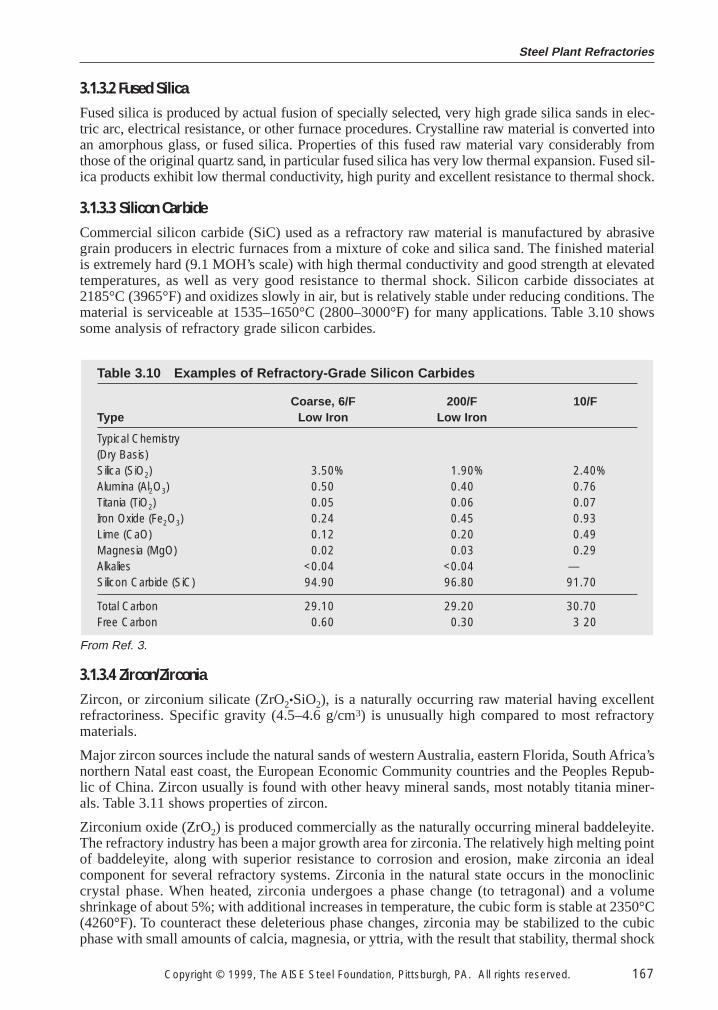
Commercial silicon carbide (SiC) used as a refractory raw material is manufactured by abrasivegrain producers in electric furnaces from a mixture of coke and silica sand. The finished materialis extremely hard (9.1 MOH’s scale) with high thermal conductivity and good strength at elevatedtemperatures, as well as very good resistance to thermal shock. Silicon carbide dissociates at2185°C (3965°F) and oxidizes slowly in air, but is relatively stable under reducing conditions. Thematerial is serviceable at 1535–1650°C (2800–3000°F) for many applications. Table 3.10 showssome analysis of refractory grade silicon carbides.
3.1.3.4 Zircon/Zirconia
Zircon, or zirconium silicate (ZrO2•SiO2), is a naturally occurring raw material having excellentrefractoriness. Specific gravity (4.5–4.6 g/cm3) is unusually high compared to most refractorymaterials.
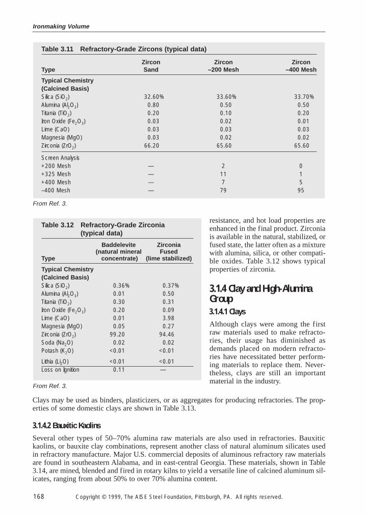
Major zircon sources include the natural sands of western Australia, eastern Florida, South Africa’snorthern Natal east coast, the European Economic Community countries and the Peoples Repub-lic of China. Zircon usually is found with other heavy mineral sands, most notably titania miner-als. Table 3.11 shows properties of zircon.
Zirconium oxide (ZrO2) is produced commercially as the naturally occurring mineral baddeleyite.The refractory industry has been a major growth area for zirconia. The relatively high melting pointof baddeleyite, along with superior resistance to corrosion and erosion, make zirconia an idealcomponent for several refractory systems. Zirconia in the natural state occurs in the monocliniccrystal phase. When heated, zirconia undergoes a phase change (to tetragonal) and a volumeshrinkage of about 5%; with additional increases in temperature, the cubic form is stable at 2350°C(4260°F). To counteract these deleterious phase changes, zirconia may be stabilized to the cubicphase with small amounts of calcia, magnesia, or yttria, with the result that stability, thermal shock
Table 3.10 Examples of Refractory-Grade Silicon Carbides
Coarse, 6/F 200/F 10/FType Low Iron Low Iron
Typical Chemistry(Dry Basis)Silica (SiO2) 3.50% 1.90% 2.40%Alumina (Al2O3) 0.50 0.40 0.76Titania (TiO2) 0.05 0.06 0.07Iron Oxide (Fe2O3) 0.24 0.45 0.93Lime (CaO) 0.12 0.20 0.49Magnesia (MgO) 0.02 0.03 0.29Alkalies <0.04 <0.04 —Silicon Carbide (SiC) 94.90 96.80 91.70
Total Carbon 29.10 29.20 30.70Free Carbon 0.60 0.30 3 20
From Ref. 3.
Ironmaking Volume
168 Copyright © 1999, The AISE Steel Foundation, Pittsburgh, PA. All rights reserved.
resistance, and hot load properties areenhanced in the final product. Zirconiais available in the natural, stabilized, orfused state, the latter often as a mixturewith alumina, silica, or other compati-ble oxides. Table 3.12 shows typicalproperties of zirconia.
3.1.4 Clay and High-AluminaGroup
3.1.4.1 Clays
Although clays were among the firstraw materials used to make refracto-ries, their usage has diminished asdemands placed on modern refracto-ries have necessitated better perform-ing materials to replace them. Never-theless, clays are still an importantmaterial in the industry.
Clays may be used as binders, plasticizers, or as aggregates for producing refractories. The prop-erties of some domestic clays are shown in Table 3.13.
3.1.4.2 Bauxitic Kaolins
Several other types of 50–70% alumina raw materials are also used in refractories. Bauxitickaolins, or bauxite clay combinations, represent another class of natural aluminum silicates usedin refractory manufacture. Major U.S. commercial deposits of aluminous refractory raw materialsare found in southeastern Alabama, and in east-central Georgia. These materials, shown in Table3.14, are mined, blended and fired in rotary kilns to yield a versatile line of calcined aluminum sil-icates, ranging from about 50% to over 70% alumina content.
Table 3.12 Refractory-Grade Zirconia (typical data)
Baddelevite Zirconia(natural mineral Fused
Type concentrate) (lime stabilized)
Typical Chemistry(Calcined Basis)Silica (SiO2) 0.36% 0.37%Alumina (Al2O3) 0.01 0.50Titania (TiO2) 0.30 0.31Iron Oxide (Fe2O3) 0.20 0.09Lime (CaO) 0.01 3.98Magnesia (MgO) 0.05 0.27Zirconia (ZrO2) 99.20 94.46Soda (Na2O) 0.02 0.02Potash (K2O) <0.01 <0.01
Lithia (Li2O) <0.01 <0.01Loss on Ignition 0.11 —
Table 3.11 Refractory-Grade Zircons (typical data)
Zircon Zircon ZirconType Sand –200 Mesh –400 Mesh
Typical Chemistry(Calcined Basis)Silica (SiO2) 32.60% 33.60% 33.70%Alumina (Al2O3) 0.80 0.50 0.50Titania (TiO2) 0.20 0.10 0.20Iron Oxide (Fe2O3) 0.03 0.02 0.01Lime (CaO) 0.03 0.03 0.03Magnesia (MgO) 0.03 0.02 0.02Zirconia (ZrO2) 66.20 65.60 65.60
Screen Analysis+200 Mesh — 2 0+325 Mesh — 11 1+400 Mesh — 7 5–400 Mesh — 79 95
From Ref. 3.
From Ref. 3.
Steel Plant Refractories
Copyright © 1999, The AISE Steel Foundation, Pittsburgh, PA. All rights reserved. 169
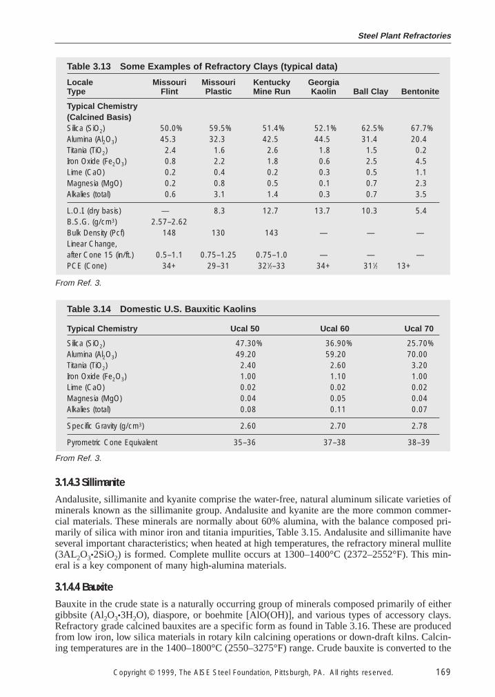
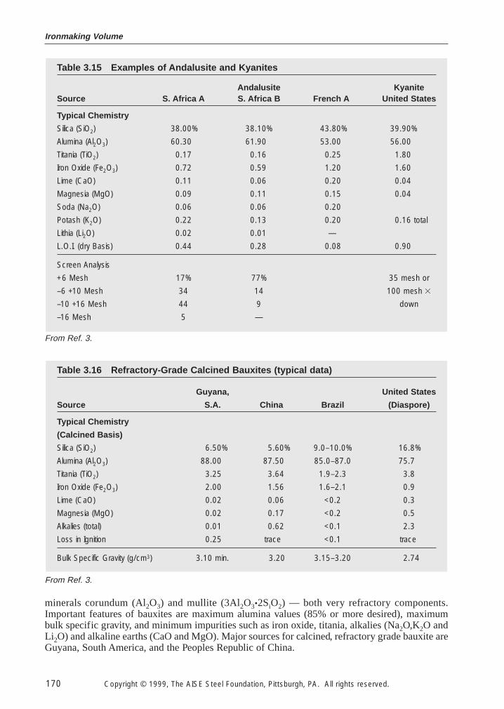
3.1.4.3 Sillimanite
Andalusite, sillimanite and kyanite comprise the water-free, natural aluminum silicate varieties ofminerals known as the sillimanite group. Andalusite and kyanite are the more common commer-cial materials. These minerals are normally about 60% alumina, with the balance composed pri-marily of silica with minor iron and titania impurities, Table 3.15. Andalusite and sillimanite haveseveral important characteristics; when heated at high temperatures, the refractory mineral mullite(3AL2O3•2SiO2) is formed. Complete mullite occurs at 1300–1400°C (2372–2552°F). This min-eral is a key component of many high-alumina materials.
3.1.4.4 Bauxite
Bauxite in the crude state is a naturally occurring group of minerals composed primarily of eithergibbsite (Al2O3•3H2O), diaspore, or boehmite [AlO(OH)], and various types of accessory clays.Refractory grade calcined bauxites are a specific form as found in Table 3.16. These are producedfrom low iron, low silica materials in rotary kiln calcining operations or down-draft kilns. Calcin-ing temperatures are in the 1400–1800°C (2550–3275°F) range. Crude bauxite is converted to the
Table 3.14 Domestic U.S. Bauxitic Kaolins
Typical Chemistry Ucal 50 Ucal 60 Ucal 70
Silica (SiO2) 47.30% 36.90% 25.70%Alumina (Al2O3) 49.20 59.20 70.00Titania (TiO2) 2.40 2.60 3.20Iron Oxide (Fe2O3) 1.00 1.10 1.00Lime (CaO) 0.02 0.02 0.02Magnesia (MgO) 0.04 0.05 0.04Alkalies (total) 0.08 0.11 0.07
Specific Gravity (g/cm3) 2.60 2.70 2.78
Pyrometric Cone Equivalent 35–36 37–38 38–39
Table 3.13 Some Examples of Refractory Clays (typical data)
Locale Missouri Missouri Kentucky GeorgiaType Flint Plastic Mine Run Kaolin Ball Clay Bentonite
Typical Chemistry(Calcined Basis)Silica (SiO2) 50.0% 59.5% 51.4% 52.1% 62.5% 67.7%Alumina (Al2O3) 45.3 32.3 42.5 44.5 31.4 20.4Titania (TiO2) 2.4 1.6 2.6 1.8 1.5 0.2Iron Oxide (Fe2O3) 0.8 2.2 1.8 0.6 2.5 4.5Lime (CaO) 0.2 0.4 0.2 0.3 0.5 1.1Magnesia (MgO) 0.2 0.8 0.5 0.1 0.7 2.3Alkalies (total) 0.6 3.1 1.4 0.3 0.7 3.5
L.O.I. (dry basis) — 8.3 12.7 13.7 10.3 5.4B.S.G. (g/cm3) 2.57–2.62Bulk Density (Pcf) 148 130 143 — — —Linear Change,after Cone 15 (in/ft.) 0.5–1.1 0.75–1.25 0.75–1.0 — — —PCE (Cone) 34+ 29–31 321⁄2–33 34+ 311⁄2 13+
From Ref. 3.
From Ref. 3.
Ironmaking Volume
170 Copyright © 1999, The AISE Steel Foundation, Pittsburgh, PA. All rights reserved.
minerals corundum (Al2O3) and mullite (3Al2O3•2SiO2) — both very refractory components.Important features of bauxites are maximum alumina values (85% or more desired), maximumbulk specific gravity, and minimum impurities such as iron oxide, titania, alkalies (Na2O,K2O andLi2O) and alkaline earths (CaO and MgO). Major sources for calcined, refractory grade bauxite areGuyana, South America, and the Peoples Republic of China.
Table 3.16 Refractory-Grade Calcined Bauxites (typical data)
Guyana, United States
Source S.A. China Brazil (Diaspore)
Typical Chemistry
(Calcined Basis)
Silica (SiO2) 6.50% 5.60% 9.0–10.0% 16.8%
Alumina (Al2O3) 88.00 87.50 85.0–87.0 75.7
Titania (TiO2) 3.25 3.64 1.9–2.3 3.8
Iron Oxide (Fe2O3) 2.00 1.56 1.6–2.1 0.9
Lime (CaO) 0.02 0.06 <0.2 0.3
Magnesia (MgO) 0.02 0.17 <0.2 0.5
Alkalies (total) 0.01 0.62 <0.1 2.3
Loss in Ignition 0.25 trace <0.1 trace
Bulk Specific Gravity (g/cm3) 3.10 min. 3.20 3.15–3.20 2.74
Table 3.15 Examples of Andalusite and Kyanites
Andalusite KyaniteSource S. Africa A S. Africa B French A United States
Typical Chemistry
Silica (SiO2) 38.00% 38.10% 43.80% 39.90%
Alumina (Al2O3) 60.30 61.90 53.00 56.00
Titania (TiO2) 0.17 0.16 0.25 1.80
Iron Oxide (Fe2O3) 0.72 0.59 1.20 1.60
Lime (CaO) 0.11 0.06 0.20 0.04
Magnesia (MgO) 0.09 0.11 0.15 0.04
Soda (Na2O) 0.06 0.06 0.20
Potash (K2O) 0.22 0.13 0.20 0.16 total
Lithia (Li2O) 0.02 0.01 —
L.O.I. (dry Basis) 0.44 0.28 0.08 0.90
Screen Analysis
+6 Mesh 17% 77% 35 mesh or
–6 +10 Mesh 34 14 100 mesh 3
–10 +16 Mesh 44 9 down
–16 Mesh 5 —
From Ref. 3.
From Ref. 3.
Steel Plant Refractories
Copyright © 1999, The AISE Steel Foundation, Pittsburgh, PA. All rights reserved. 171
Bauxite
Size reduction
Extractionof
aluminum hydroxides
Impurityseparation
and washing
Strongliquor
Make-upNaOH
Residue
Precipitationof
crystalline Al(OH)3
Concentrationby
evaporation
Seed
Weakliquor
Productseparation
and washing
Dehydrationby
calcination
Al(OH)3
Alumina(Al2O3)
Fig. 3.2 Schematic of Bayer process.
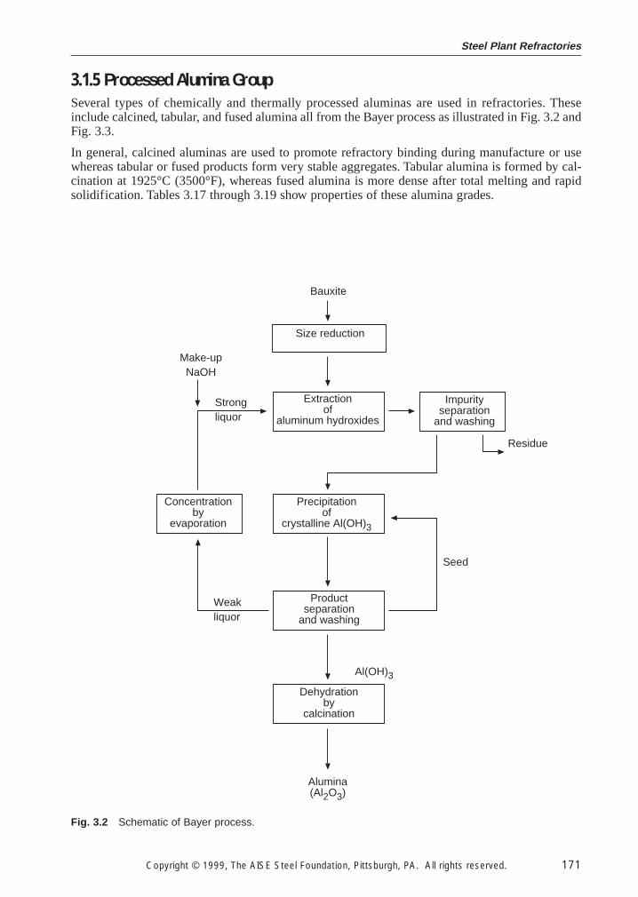
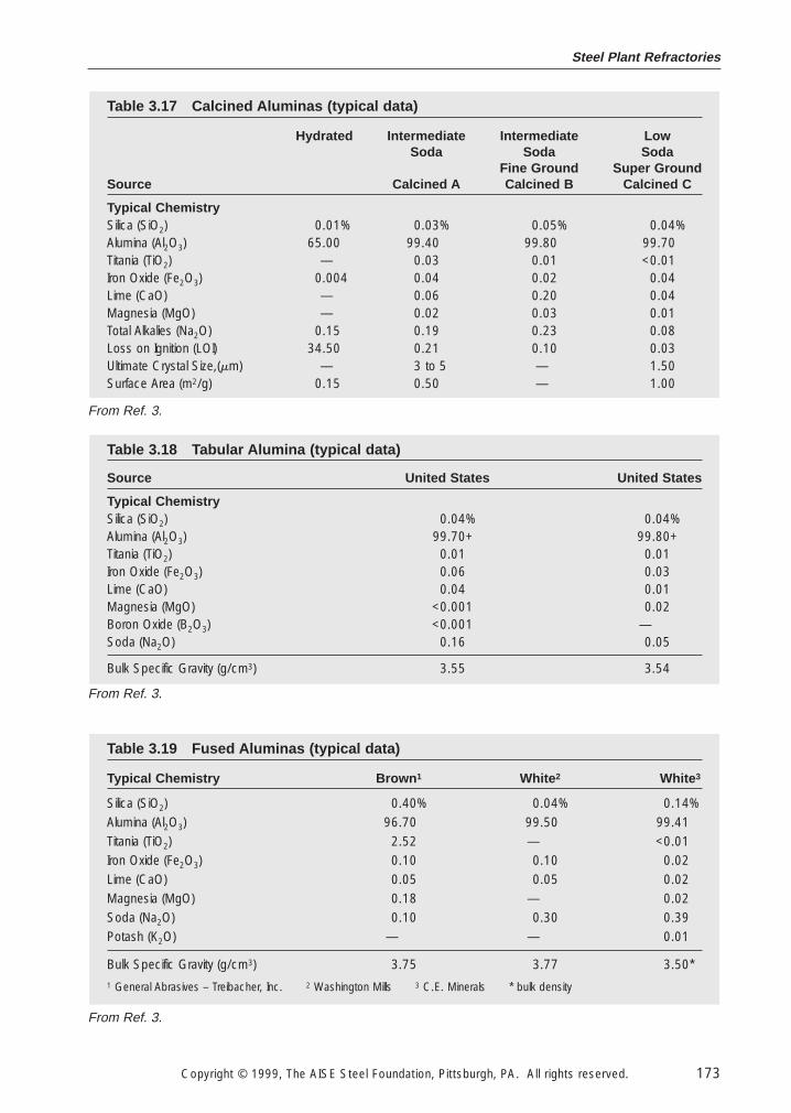
3.1.5 Processed Alumina Group
Several types of chemically and thermally processed aluminas are used in refractories. Theseinclude calcined, tabular, and fused alumina all from the Bayer process as illustrated in Fig. 3.2 andFig. 3.3.
In general, calcined aluminas are used to promote refractory binding during manufacture or usewhereas tabular or fused products form very stable aggregates. Tabular alumina is formed by cal-cination at 1925°C (3500°F), whereas fused alumina is more dense after total melting and rapidsolidification. Tables 3.17 through 3.19 show properties of these alumina grades.

Ironmaking Volume
172 Copyright © 1999, The AISE Steel Foundation, Pittsburgh, PA. All rights reserved.
Primaryprocess
Secondaryprocess Market
Glass and ceramics
Auto catalyst substratesWear-resistant ceramicWhitewaresSpark plugsPorcelain insulatorsSubstratesPolishingRefractoriesKiln furnitureCeramic tileGlass
Translucent ceramicCutting toolsBiomedical ceramicSynthetic gemsLens polishing
Catalyst bed supportFilter mediaHeat exchange media
Kiln furnitureRefractories
Catalyst bed supportAbrasives
Electrode coatingsResin filler
Ruby abrasive grainPink abrasive grainWhite abrasive grainFused castFibers
Application
Drying
Grinding
Pelletizing
Sintering
(Spheres)
Crushing
Sizing
(Grain)
Fusion
Industrial chemicals
Ceramics, polishingand refractories
High-purityaluminas
Industrial chemicals
Refractories
Industrial chemicals
Fillers and coatings
Abrasives
Refractories
Bayer processrefinery
Aluminumhydroxide
Calcination
Calcinedaluminas
Primaryaluminumsmelters
Fig. 3.3 Products of Bayer Process.
3.1.6 Carbon Group
Various carbon forms are used to an ever increasing extent in refractories. For example, modernrefractories use various graphite forms in combination with oxides to impart special properties.The graphite may be synthetic in nature as produced by heating calcined petroleum coke to 3000°C(5400°F) or may be natural graphite(s) from China, Mexico, Canada etc. Some all-carbon or all-graphite refractories may be produced for applications in highly reducing atmospheres.
Steel Plant Refractories
Copyright © 1999, The AISE Steel Foundation, Pittsburgh, PA. All rights reserved. 173
Table 3.19 Fused Aluminas (typical data)
Typical Chemistry Brown 1 White 2 White 3
Silica (SiO2) 0.40% 0.04% 0.14%
Alumina (Al2O3) 96.70 99.50 99.41
Titania (TiO2) 2.52 — <0.01
Iron Oxide (Fe2O3) 0.10 0.10 0.02
Lime (CaO) 0.05 0.05 0.02
Magnesia (MgO) 0.18 — 0.02
Soda (Na2O) 0.10 0.30 0.39
Potash (K2O) — — 0.01
Bulk Specific Gravity (g/cm3) 3.75 3.77 3.50*
1 General Abrasives – Treibacher, Inc. 2 Washington Mills 3 C.E. Minerals * bulk density
Table 3.18 Tabular Alumina (typical data)
Source United States United States
Typical ChemistrySilica (SiO2) 0.04% 0.04%Alumina (Al2O3) 99.70+ 99.80+Titania (TiO2) 0.01 0.01Iron Oxide (Fe2O3) 0.06 0.03Lime (CaO) 0.04 0.01Magnesia (MgO) <0.001 0.02Boron Oxide (B2O3) <0.001 —Soda (Na2O) 0.16 0.05
Bulk Specific Gravity (g/cm3) 3.55 3.54
Table 3.17 Calcined Aluminas (typical data)
Hydrated Intermediate Intermediate LowSoda Soda Soda
Fine Ground Super GroundSource Calcined A Calcined B Calcined C
Typical ChemistrySilica (SiO2) 0.01% 0.03% 0.05% 0.04%Alumina (Al2O3) 65.00 99.40 99.80 99.70Titania (TiO2) — 0.03 0.01 <0.01Iron Oxide (Fe2O3) 0.004 0.04 0.02 0.04Lime (CaO) — 0.06 0.20 0.04Magnesia (MgO) — 0.02 0.03 0.01Total Alkalies (Na2O) 0.15 0.19 0.23 0.08Loss on Ignition (LOI) 34.50 0.21 0.10 0.03Ultimate Crystal Size,(mm) — 3 to 5 — 1.50Surface Area (m2/g) 0.15 0.50 — 1.00
From Ref. 3.
From Ref. 3.
From Ref. 3.
Ironmaking Volume
174 Copyright © 1999, The AISE Steel Foundation, Pittsburgh, PA. All rights reserved.
Generally, graphites are used in refractories in order to reduce the wetting characteristics of therefractory material with respect to slag corrosion and to increase the thermal conductivity whichwill result in better thermal shock resistance. In oxide-carbon refractories, the carbon content mayrange anywhere from as low as 4–5% up to as high as 30–35%. Note that as the graphitic contentincreases, the thermal conductivity of the refractory increases, but the density of the refractorydecreases. This result is primarily due to the fact that the density of graphite is much less than thedensity of the other refractory materials being used. There are other contrasting differences in themorphology of the graphite as compared to the other refractory materials. The graphite materials,which are used in refractories, are commonly of a flaky structure; therefore, these flakes do notlend themselves to the same particle packing phenomena as do granular particles.
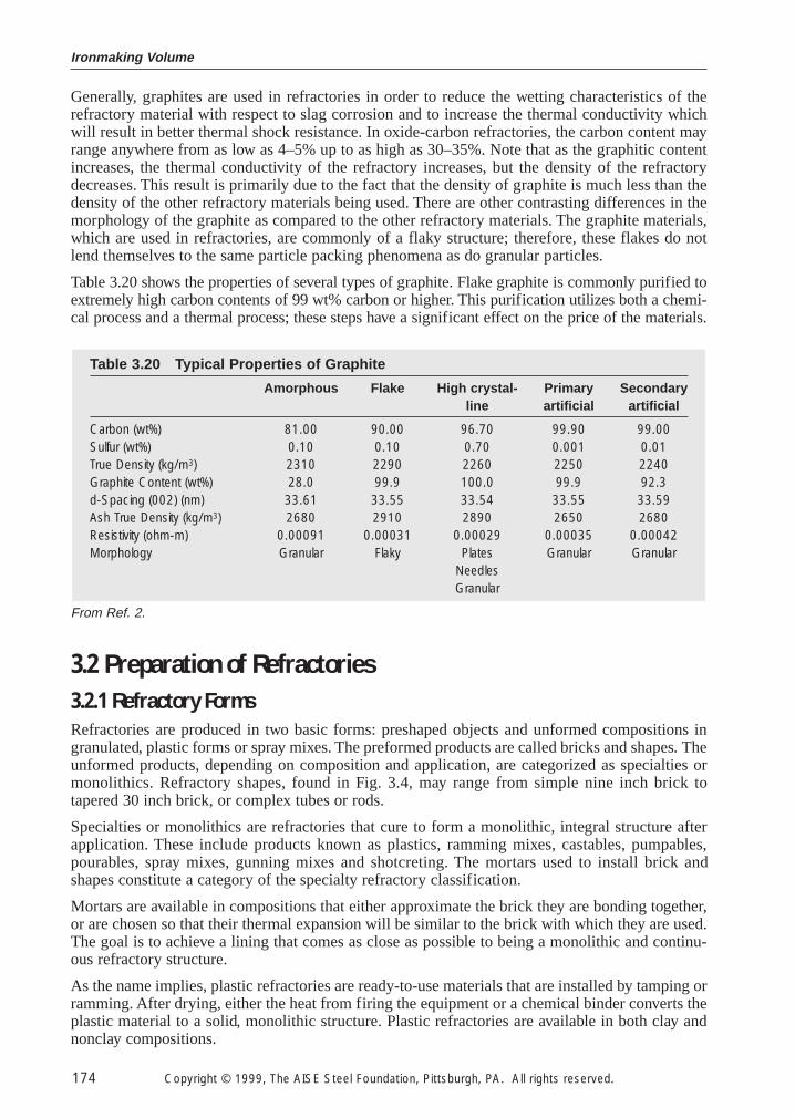
Table 3.20 shows the properties of several types of graphite. Flake graphite is commonly purified toextremely high carbon contents of 99 wt% carbon or higher. This purification utilizes both a chemi-cal process and a thermal process; these steps have a significant effect on the price of the materials.
3.2 Preparation of Refractories
3.2.1 Refractory Forms
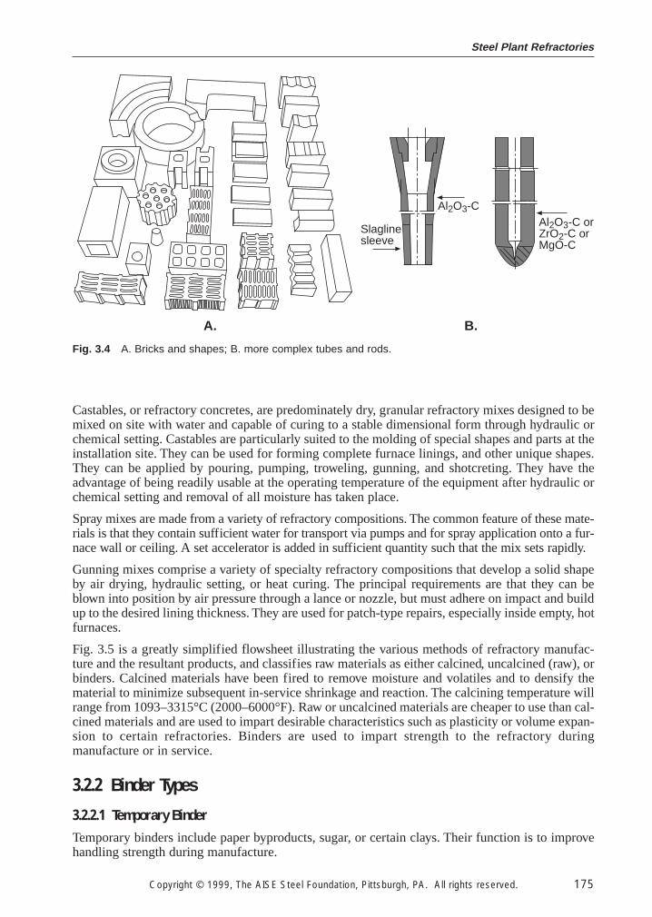
Refractories are produced in two basic forms: preshaped objects and unformed compositions ingranulated, plastic forms or spray mixes. The preformed products are called bricks and shapes. Theunformed products, depending on composition and application, are categorized as specialties ormonolithics. Refractory shapes, found in Fig. 3.4, may range from simple nine inch brick totapered 30 inch brick, or complex tubes or rods.
Specialties or monolithics are refractories that cure to form a monolithic, integral structure afterapplication. These include products known as plastics, ramming mixes, castables, pumpables,pourables, spray mixes, gunning mixes and shotcreting. The mortars used to install brick andshapes constitute a category of the specialty refractory classification.
Mortars are available in compositions that either approximate the brick they are bonding together,or are chosen so that their thermal expansion will be similar to the brick with which they are used.The goal is to achieve a lining that comes as close as possible to being a monolithic and continu-ous refractory structure.
As the name implies, plastic refractories are ready-to-use materials that are installed by tamping orramming. After drying, either the heat from firing the equipment or a chemical binder converts theplastic material to a solid, monolithic structure. Plastic refractories are available in both clay andnonclay compositions.
Table 3.20 Typical Properties of Graphite
Amorphous Flake High crystal- Primary Secondaryline artificial artificial
Carbon (wt%) 81.00 90.00 96.70 99.90 99.00Sulfur (wt%) 0.10 0.10 0.70 0.001 0.01True Density (kg/m3) 2310 2290 2260 2250 2240Graphite Content (wt%) 28.0 99.9 100.0 99.9 92.3d-Spacing (002) (nm) 33.61 33.55 33.54 33.55 33.59Ash True Density (kg/m3) 2680 2910 2890 2650 2680Resistivity (ohm-m) 0.00091 0.00031 0.00029 0.00035 0.00042Morphology Granular Flaky Plates Granular Granular
NeedlesGranular
From Ref. 2.
Steel Plant Refractories
Copyright © 1999, The AISE Steel Foundation, Pittsburgh, PA. All rights reserved. 175
Castables, or refractory concretes, are predominately dry, granular refractory mixes designed to bemixed on site with water and capable of curing to a stable dimensional form through hydraulic orchemical setting. Castables are particularly suited to the molding of special shapes and parts at theinstallation site. They can be used for forming complete furnace linings, and other unique shapes.They can be applied by pouring, pumping, troweling, gunning, and shotcreting. They have theadvantage of being readily usable at the operating temperature of the equipment after hydraulic orchemical setting and removal of all moisture has taken place.
Spray mixes are made from a variety of refractory compositions. The common feature of these mate-rials is that they contain sufficient water for transport via pumps and for spray application onto a fur-nace wall or ceiling. A set accelerator is added in sufficient quantity such that the mix sets rapidly.
Gunning mixes comprise a variety of specialty refractory compositions that develop a solid shapeby air drying, hydraulic setting, or heat curing. The principal requirements are that they can beblown into position by air pressure through a lance or nozzle, but must adhere on impact and buildup to the desired lining thickness. They are used for patch-type repairs, especially inside empty, hotfurnaces.
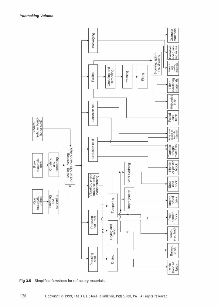
Fig. 3.5 is a greatly simplified flowsheet illustrating the various methods of refractory manufac-ture and the resultant products, and classifies raw materials as either calcined, uncalcined (raw), orbinders. Calcined materials have been fired to remove moisture and volatiles and to densify thematerial to minimize subsequent in-service shrinkage and reaction. The calcining temperature willrange from 1093–3315°C (2000–6000°F). Raw or uncalcined materials are cheaper to use than cal-cined materials and are used to impart desirable characteristics such as plasticity or volume expan-sion to certain refractories. Binders are used to impart strength to the refractory duringmanufacture or in service.
3.2.2 Binder Types
3.2.2.1 Temporary Binder
Temporary binders include paper byproducts, sugar, or certain clays. Their function is to improvehandling strength during manufacture.
Fig. 3.4 A. Bricks and shapes; B. more complex tubes and rods.
Slaglinesleeve
Al2O3-CAl2O3-C orZrO2-C orMgO-C
A. B.
Ironmaking Volume
176 Copyright © 1999, The AISE Steel Foundation, Pittsburgh, PA. All rights reserved.
Raw
mat
eria
ls,
unfir
ed
Raw
mat
eria
ls,
fired
Bin
ders
(sol
id o
r liq
uid-
hot o
r co
ld)
Cru
shin
gan
dsc
reen
ing
Cru
shin
gan
dsc
reen
ing
Mix
ing
- bl
endi
ng(h
ot o
r co
ld -
wet
or
dry)
Pre
ssin
gco
ldP
ress
ing
hot -
mix
Vib
ratio
n, p
neu-
mat
ic r
amm
ing
hand
form
ing
Tem
perin
gD
ryin
g an
dfir
ing
Dry
ing
Res
inbo
nded
bric
k
Bur
ned
bric
kT
emp-
ered
bric
kP
itch
bond
edbr
ick
Impr
eg-
nate
dbr
ick
Ste
el-
clad
bric
k
Pla
stic
or p
last
icbl
ock
Tap
hole
trou
ghm
ater
ials
Anh
ydro
uspl
astic
or
taph
ole
mat
eria
l
Fus
edca
stbr
ick
Reb
onde
dbr
ick
Fib
erin
sula
ting
mat
eria
ls
Mor
tars
and
seal
ing
mat
eria
ls
Cas
tabl
esan
d gu
nn-
ing
mix
es
Gra
nula
rm
ater
ials
Blo
win
g, s
pinn
-in
g, d
raw
ing
Firi
ng
Pre
ssin
g
Cru
shin
g an
dsc
reen
ing
Fus
ion
Pac
kagi
ngE
xtru
sion
hot
Ext
rusi
on c
old
Impr
egna
tion
Ste
el c
ladd
ing
Fig 3.5 Simplified flowsheet for refractory materials.
Steel Plant Refractories
Copyright © 1999, The AISE Steel Foundation, Pittsburgh, PA. All rights reserved. 177
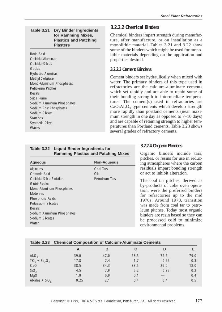
3.2.2.2 Chemical BindersChemical binders impart strength during manufac-ture, after manufacture, or on installation as amonolithic material. Tables 3.21 and 3.22 showsome of the binders which might be used for mono-lithic materials depending on the application andproperties desired.
3.2.2.3 Cement Binders
Cement binders set hydraulically when mixed withwater. The primary binders of this type used inrefractories are the calcium-aluminate cementswhich set rapidly and are able to retain some oftheir bonding strength to intermediate tempera-tures. The cement(s) used in refractories areCaO•Al2O3 type cements which develop strengthmore rapidly than portland cements (near maxi-mum strength in one day as opposed to 7–10 days)and are capable of retaining strength to higher tem-peratures than Portland cements. Table 3.23 showsseveral grades of refractory cements.
3.2.2.4 Organic Binders
Organic binders include tars,pitches, or resins for use in reduc-ing atmospheres where the carbonresiduals impart bonding strengthor act to inhibit alteration.
The coal tar pitches, derived asby-products of coke oven opera-tion, were the preferred bindersfor refractories up to the mid1970s. Around 1978, transitionwas made from coal tar to petro-leum pitches. Today most organicbinders are resin based so they canbe processed cold to minimizeenvironmental problems.
Table 3.23 Chemical Composition of Calcium-Aluminate Cements
A B C D E
Al2O3 39.0 47.0 58.5 72.5 79.0TiO2 + Fe2O3 17.8 7.4 1.7 0.25 0.3CaO 38.5 34.3 33.5 26.0 18.0SiO2 4.5 7.9 5.2 0.35 0.2MgO 1.0 0.9 0.1 — 0.4Alkalies + SO3 0.25 2.1 0.4 0.4 0.5
Table 3.22 Liquid Binder Ingredients for Ramming Plastics and Patching Mixes
Aqueous Non-Aqueous
Alginates Coal TarsChromic Acid OilsColloidal Silica Solution Petroleum TarsGlutrinResinsMono Aluminum PhosphatesMolassesPhosphoric AcidsPotassium SilicatesResinsSodium Aluminum PhosphatesSodium SilicatesWater
Table 3.21 Dry Binder Ingredientsfor Ramming Mixes,Plastics and PatchingPlasters
Boric AcidColloidal AluminasColloidal SilicasGoulacHydrated AluminasMethyl CelluloseMono-Aluminum PhosphatesPetroleum PitchesResinsSilica FumeSodium Aluminum PhosphatesSodium Poly PhosphatesSodium SilicateStarchesSynthetic ClaysWaxes
Ironmaking Volume
178 Copyright © 1999, The AISE Steel Foundation, Pittsburgh, PA. All rights reserved.
Phenolic resins, the most important synthetic binders for refractory materials, are condensationproducts of phenol and formaldehyde. These resins are differentiated according to whether theyrepresent novolacs or self curing resoles. The versatility of phenolic resins is derived from the var-ious bonding functions that they can provide. Among other things phenolic resins can provide anintermediate bonding function associated with a thermosetting range of properties during produc-tion of refractory bricks and, at a later stage, are capable of forming (polymeric) carbon bypyrolytic decomposition. In the form of bonding carbon, these results contribute to the quality ofthe products.
3.2.3 Processing
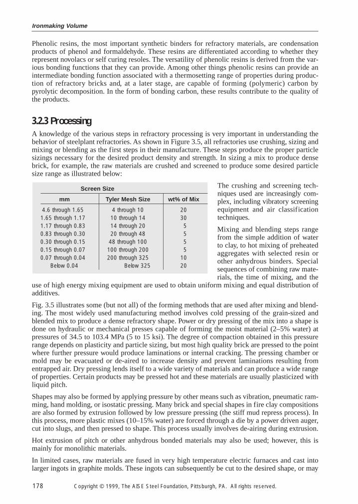
A knowledge of the various steps in refractory processing is very important in understanding thebehavior of steelplant refractories. As shown in Figure 3.5, all refractories use crushing, sizing andmixing or blending as the first steps in their manufacture. These steps produce the proper particlesizings necessary for the desired product density and strength. In sizing a mix to produce densebrick, for example, the raw materials are crushed and screened to produce some desired particlesize range as illustrated below:
The crushing and screening tech-niques used are increasingly com-plex, including vibratory screeningequipment and air classificationtechniques.
Mixing and blending steps rangefrom the simple addition of waterto clay, to hot mixing of preheatedaggregates with selected resin orother anhydrous binders. Specialsequences of combining raw mate-rials, the time of mixing, and the
use of high energy mixing equipment are used to obtain uniform mixing and equal distribution ofadditives.
Fig. 3.5 illustrates some (but not all) of the forming methods that are used after mixing and blend-ing. The most widely used manufacturing method involves cold pressing of the grain-sized andblended mix to produce a dense refractory shape. Power or dry pressing of the mix into a shape isdone on hydraulic or mechanical presses capable of forming the moist material (2–5% water) atpressures of 34.5 to 103.4 MPa (5 to 15 ksi). The degree of compaction obtained in this pressurerange depends on plasticity and particle sizing, but most high quality brick are pressed to the pointwhere further pressure would produce laminations or internal cracking. The pressing chamber ormold may be evacuated or de-aired to increase density and prevent laminations resulting fromentrapped air. Dry pressing lends itself to a wide variety of materials and can produce a wide rangeof properties. Certain products may be pressed hot and these materials are usually plasticized withliquid pitch.
Shapes may also be formed by applying pressure by other means such as vibration, pneumatic ram-ming, hand molding, or isostatic pressing. Many brick and special shapes in fire clay compositionsare also formed by extrusion followed by low pressure pressing (the stiff mud repress process). Inthis process, more plastic mixes (10–15% water) are forced through a die by a power driven auger,cut into slugs, and then pressed to shape. This process usually involves de-airing during extrusion.
Hot extrusion of pitch or other anhydrous bonded materials may also be used; however, this ismainly for monolithic materials.
In limited cases, raw materials are fused in very high temperature electric furnaces and cast intolarger ingots in graphite molds. These ingots can subsequently be cut to the desired shape, or may
Screen Size
mm Tyler Mesh Size wt% of Mix
4.6 through 1.65 4 through 10 201.65 through 1.17 10 through 14 301.17 through 0.83 14 through 20 50.83 through 0.30 20 through 48 50.30 through 0.15 48 through 100 50.15 through 0.07 100 through 200 50.07 through 0.04 200 through 325 10
Below 0.04 Below 325 20
Steel Plant Refractories
Copyright © 1999, The AISE Steel Foundation, Pittsburgh, PA. All rights reserved. 179
be broken and crushed into a refractory raw material for use in conventional powder pressed brickor for use in monoliths. In still another process, molten refractory may be blown, drawn, or spuninto fibers for subsequent use in forming mats, blankets, or boards.
Many refractory materials are used in bulk form. Sized, granular refractories may be used in dryform or mixed with water at the plant site before installation by casting or gunning. Wet extrudedmaterial may be packaged to avoid drying and shipped to the plant site ready for application byramming into place as a large monolithic structure. Wet bonding mortars may be shipped in sealedcontainers ready for use.
As shown in Fig. 3.5 many products are prefired before shipment. The purpose of firing is to pro-duce dimensionally stable products having specific properties. Firing in modern refractory plantsis accomplished in continuous or tunnel kilns.
In tunnel kiln firing, which is usually preceded by tunnel drying, the unfired brick loaded on smallcars are passed slowly through a long tunnel shaped refractory lined structure, divided successivelyinto preheating, firing and cooling zones, generally taking three to five days for the trip. This timewill vary widely, however, with the product being fired. Products of combustion from the fuelburned in the firing zone pass into the preheating zone (countercurrent to the direction of travel ofthe cars onto which the brick are stacked) and give up their heat to the oncoming loads of brick.Some refractories are also fired in batch or periodic kilns where two to four week cycles are usedfor heating, cooling, and loading and unloading kilns.
Temperatures of firing are important regardless of the type of kiln used, because both the quality andproperties of the brick may be affected. The final properties and behavior of most brick can be mod-ified by firing them in an oxidizing or a reducing atmosphere. By controlling the rate of heating andthe maximum soaking temperature and soaking time, change in the crystalline structure can beeffected, which in turn can also affect the service performance of the brick. In general, the objectivesin firing are to (a) drive off hygroscopic, combined water, and CO2; (b) bring about desired chemi-cal changes such as oxidizing iron and sulfur compounds, and organic matter, etc; (c) effect trans-formations of the mineral constituents and convert them to the most stable forms; and (d) effectnecessary combinations and vitrification of bonding agents. Firing temperatures vary from as low as1093°C (2000°F) for certain fireclay materials to over 1770°C (3200°F) for some basic products.
Certain refractories with carbon binders or containing oxidizable constituents may be indirectly firedinside muffles to prevent oxidation or may be packed in coke or graphite during firing for the samepurpose. One grade of carbon refractory is hot pressed by electrically heating it during pressing. Thisaccomplishes the forming and thermal treatment of the refractory in a single step. Nitrogen or otherspecial atmospheres may be used to impart special binding phases such as silicon nitride.
Manufacturing processes for making lightweight or insulating brick aim for high porosity, prefer-ably with a fine pore structure. This is accomplished by mixing a bulky combustible substance, likesawdust or ground cork, or volatile solid, such as napthalene, with the wet batch, by forcing air intothe wet plastic mass, or by mixing into the batch reagents which will react chemically to form agas and a product not injurious to the brick. In firing such brick, the combustible or volatile mate-rial is eliminated and the remaining refractory structure is rigidized. Low density, pre-expandedaggregate may also be used to make products by conventional brickmaking methods.
Some processing after the fired brick are produced may also be performed. For example the brick maybe steelcased for use in applications where oxidization of the steel case between brick serves to weldor hold the brick together. Many brick types are also impregnated by placing the fired brick into vac-uum tanks and introducing liquid pitch or resins into the brick pore structure. This treatment resultsin formation of a carbon phase in service which has highly beneficial effects in some applications.
3.2.4 ProductsWith the large number of raw material types, refractory forms, and manufacturing techniques amultitude of refractory products are produced. A significant number of them are currently used inthe iron and steel industry. This chapter and the one that follows will present considerable moredetail regarding the specific uses of refractories.
Ironmaking Volume
180 Copyright © 1999, The AISE Steel Foundation, Pittsburgh, PA. All rights reserved.
3.3 Chemical and Physical Characteristics of Refractories andtheir Relation to Service Conditions
The foregoing discussions have indicated that there is a wide variety of refractories from the stand-point of raw materials, overall composition, and method of manufacture. The requirements forrefractories are equally diverse. Analysis of service conditions in iron and steelmaking in generalshows that refractories are required to withstand:
1. A wide range of temperature, up to 2200°C (4000°F).
2. Sudden changes in temperature; high tensile stresses accompanying these rapidtemperature changes cause thermal shock which result in cracking or fracturing.
3. Low levels of compressive stresses at both high and low temperatures.
4. Abrasive forces at both high and low temperatures.
5. The corrosive action of slags, ranging from acidic to basic in character.
6. The action of molten metals, always at high temperatures and capable of exertinggreat pressures and buoyant forces.
7. The action of gasses, including CO, SO2, Cl, CH4, H2O, and volatile oxides and saltsof metals. All are capable of penetrating and reacting with the refractory.
8. As a refractory is being subjected to one or more of the previously stated conditions,it usually functions as a highly effective insulator, or may also be required to be aconductor or absorber of heat depending on its application. The refractory also mustperform without exposing workers or environments to unsafe or unhealthy condi-tions at all times.
As any particular service environment usually involves more than one of the above factors, prede-termining the life of a refractory is a complex process involving information on physical and ther-mal properties as determined by laboratory testing, analysis of the effect of service or processconditions and media on the refractory, and a knowledge of the fundamental reactions betweenrefractories and the various contaminants encountered in service. In this section the physical andchemical characteristics of selected refractories as measured in a variety of laboratory tests will bedescribed as a general guide to understanding the complex nature of these materials in relation totheir service environments.
3.3.1 Chemical Composition
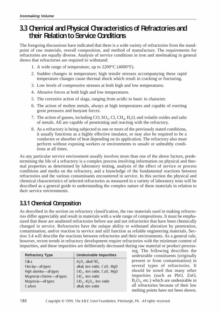
As described in the section on refractory classification, the raw materials used in making refracto-ries differ appreciably and result in materials with a wide range of compositions. It must be empha-sized that these are unaltered refractories before use and not refractories that have been chemicallychanged in service. Refractories have the unique ability to withstand alteration by penetration,contamination, and/or reaction in service and still function as reliable engineering materials. Sec-tion 3.4 will describe the reactions between refractories and their environments. As a general rule,however, recent trends in refractory development require refractories with the minimum content ofimpurities, and these impurities are deliberately decreased during raw material or product process-
ing. The following describes theundesirable constituents (originallypresent or from contamination) inseveral types of refractories. Itshould be noted that many otherimpurities (such as PbO, ZnO,B2O3, etc.) which are undesirable inall refractories because of their lowmelting points have not been shown.
Refractory Type Undesirable Impurities
Silica Al2O2 alkali TiO2
Fireclay—all types alkali, iron oxide, CaO, MgOHigh alumina—all types SiO2, iron oxide, CaO, MgOMagnesia-chrome—all types SiO2, iron oxideMagnesia—all types SiO2, Al2O3, iron oxideCarbon alkali, iron oxide
Steel Plant Refractories
Copyright © 1999, The AISE Steel Foundation, Pittsburgh, PA. All rights reserved. 181
The importance of composition will be described in Section 3.4 where phase diagrams will be usedto indicate the reactions in refractories and their environment at elevated temperatures.
3.3.2 Density and Porosity
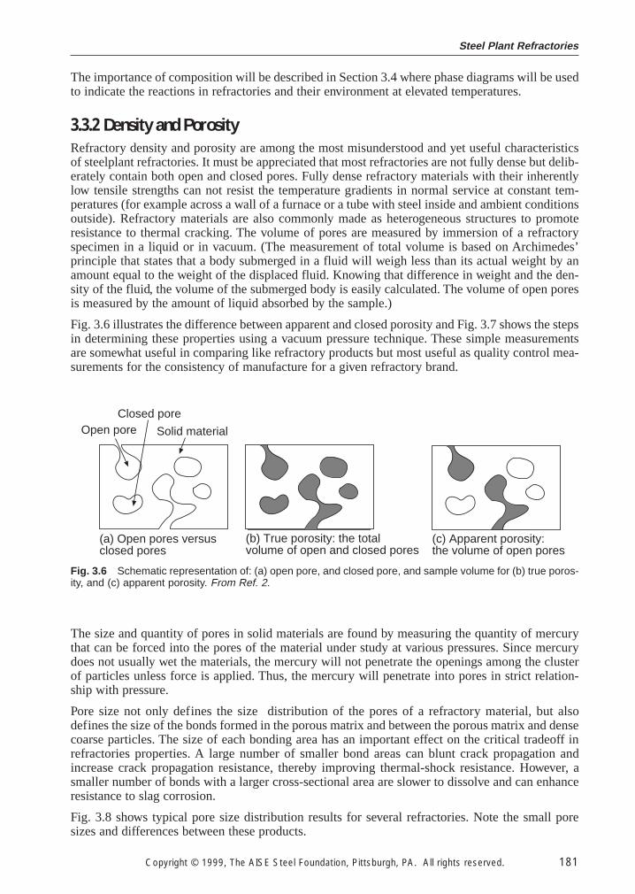
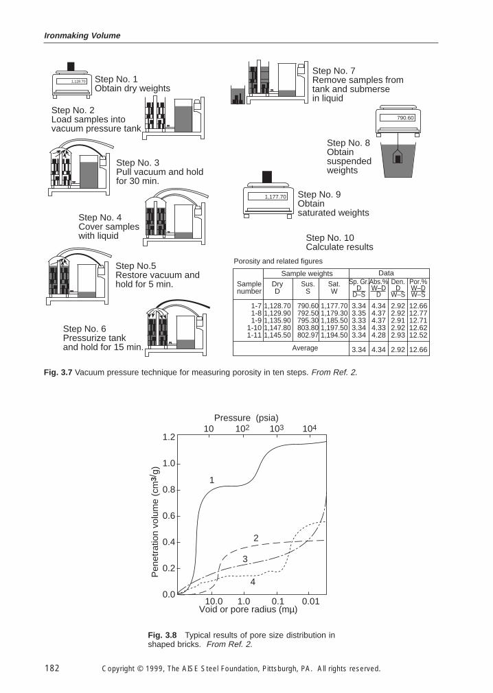
Refractory density and porosity are among the most misunderstood and yet useful characteristicsof steelplant refractories. It must be appreciated that most refractories are not fully dense but delib-erately contain both open and closed pores. Fully dense refractory materials with their inherentlylow tensile strengths can not resist the temperature gradients in normal service at constant tem-peratures (for example across a wall of a furnace or a tube with steel inside and ambient conditionsoutside). Refractory materials are also commonly made as heterogeneous structures to promoteresistance to thermal cracking. The volume of pores are measured by immersion of a refractoryspecimen in a liquid or in vacuum. (The measurement of total volume is based on Archimedes’principle that states that a body submerged in a fluid will weigh less than its actual weight by anamount equal to the weight of the displaced fluid. Knowing that difference in weight and the den-sity of the fluid, the volume of the submerged body is easily calculated. The volume of open poresis measured by the amount of liquid absorbed by the sample.)
Fig. 3.6 illustrates the difference between apparent and closed porosity and Fig. 3.7 shows the stepsin determining these properties using a vacuum pressure technique. These simple measurementsare somewhat useful in comparing like refractory products but most useful as quality control mea-surements for the consistency of manufacture for a given refractory brand.
Open poreClosed pore
Solid material
(a) Open pores versusclosed pores
(c) Apparent porosity:the volume of open pores
(b) True porosity: the totalvolume of open and closed pores
Fig. 3.6 Schematic representation of: (a) open pore, and closed pore, and sample volume for (b) true poros-ity, and (c) apparent porosity. From Ref. 2.
The size and quantity of pores in solid materials are found by measuring the quantity of mercurythat can be forced into the pores of the material under study at various pressures. Since mercurydoes not usually wet the materials, the mercury will not penetrate the openings among the clusterof particles unless force is applied. Thus, the mercury will penetrate into pores in strict relation-ship with pressure.
Pore size not only defines the size distribution of the pores of a refractory material, but alsodefines the size of the bonds formed in the porous matrix and between the porous matrix and densecoarse particles. The size of each bonding area has an important effect on the critical tradeoff inrefractories properties. A large number of smaller bond areas can blunt crack propagation andincrease crack propagation resistance, thereby improving thermal-shock resistance. However, asmaller number of bonds with a larger cross-sectional area are slower to dissolve and can enhanceresistance to slag corrosion.
Fig. 3.8 shows typical pore size distribution results for several refractories. Note the small poresizes and differences between these products.
Ironmaking Volume
182 Copyright © 1999, The AISE Steel Foundation, Pittsburgh, PA. All rights reserved.
Step No. 1Obtain dry weights
1,128.70
1,177.70
790.60Step No. 2Load samples intovacuum pressure tank
Step No. 3Pull vacuum and holdfor 30 min.
Step No. 4Cover sampleswith liquid
Step No.5Restore vacuum andhold for 5 min.
Step No. 6Pressurize tankand hold for 15 min.
Step No. 7Remove samples fromtank and submersein liquid
Step No. 8Obtainsuspendedweights
Step No. 9Obtainsaturated weights
Step No. 10Calculate results
Porosity and related figures
Samplenumber
1-71-81-9
1-101-11
Sample weights Data
DryD
1,128.701,129.901,135.901,147.801,145.50
Sus.S
790.60792.50795.30803.80802.97
Sat.W
1,177.701,179.301,185.501,197.501,194.50
Average
Sp. Gr.D
D–S
3.343.353.333.343.34
3.34
Abs.%W–D
D
4.344.374.374.334.28
4.34
Den.D
W–S
2.922.922.912.922.93
2.92
Por.%W–DW–S
12.6612.7712.7112.6212.52
12.66
Fig. 3.7 Vacuum pressure technique for measuring porosity in ten steps. From Ref. 2.
Pressure (psia)10 102 103 104
1.2
1.0
0.8
0.6
0.4
0.2
0.0
Pen
etra
tion
volu
me
(cm
3/g)
10.0 1.0 0.1 0.01Void or pore radius (mµ)
1
2
3
4
Fig. 3.8 Typical results of pore size distribution inshaped bricks. From Ref. 2.
Steel Plant Refractories
Copyright © 1999, The AISE Steel Foundation, Pittsburgh, PA. All rights reserved. 183
3.3.3 Refractoriness
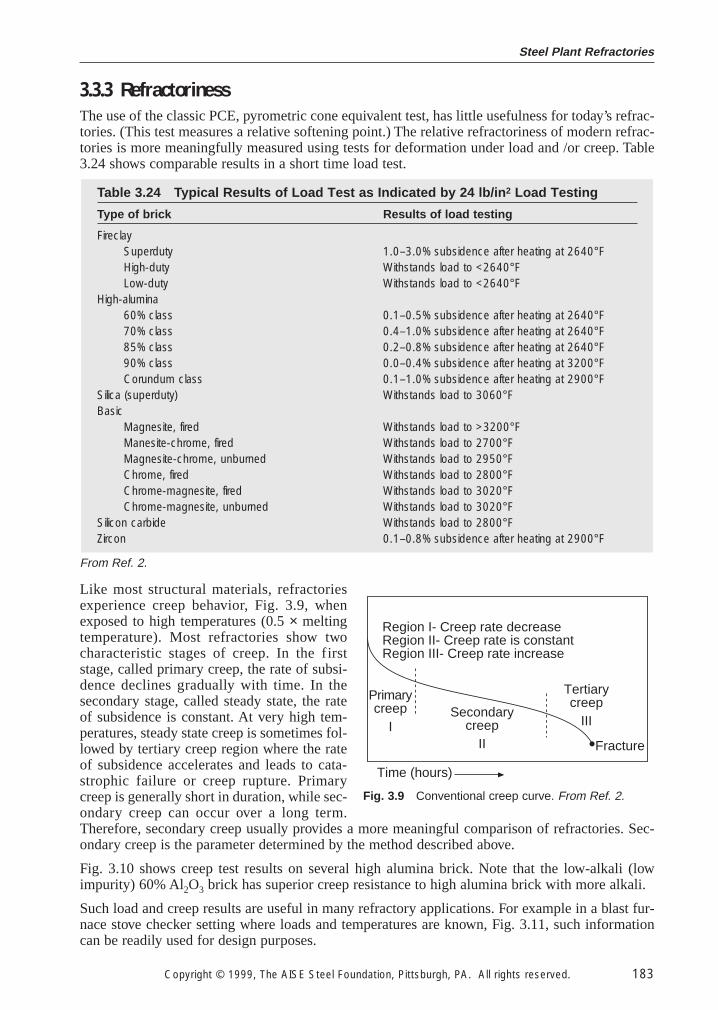
The use of the classic PCE, pyrometric cone equivalent test, has little usefulness for today’s refrac-tories. (This test measures a relative softening point.) The relative refractoriness of modern refrac-tories is more meaningfully measured using tests for deformation under load and /or creep. Table3.24 shows comparable results in a short time load test.
Like most structural materials, refractoriesexperience creep behavior, Fig. 3.9, whenexposed to high temperatures (0.5 × meltingtemperature). Most refractories show twocharacteristic stages of creep. In the firststage, called primary creep, the rate of subsi-dence declines gradually with time. In thesecondary stage, called steady state, the rateof subsidence is constant. At very high tem-peratures, steady state creep is sometimes fol-lowed by tertiary creep region where the rateof subsidence accelerates and leads to cata-strophic failure or creep rupture. Primarycreep is generally short in duration, while sec-ondary creep can occur over a long term.Therefore, secondary creep usually provides a more meaningful comparison of refractories. Sec-ondary creep is the parameter determined by the method described above.
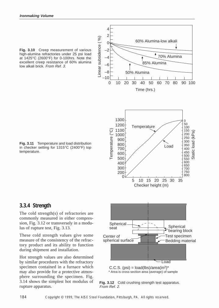
Fig. 3.10 shows creep test results on several high alumina brick. Note that the low-alkali (lowimpurity) 60% Al2O3 brick has superior creep resistance to high alumina brick with more alkali.
Such load and creep results are useful in many refractory applications. For example in a blast fur-nace stove checker setting where loads and temperatures are known, Fig. 3.11, such informationcan be readily used for design purposes.
Table 3.24 Typical Results of Load Test as Indicated by 24 lb/in 2 Load Testing
Type of brick Results of load testing
FireclaySuperduty 1.0–3.0% subsidence after heating at 2640°FHigh-duty Withstands load to <2640°FLow-duty Withstands load to <2640°F
High-alumina60% class 0.1–0.5% subsidence after heating at 2640°F70% class 0.4–1.0% subsidence after heating at 2640°F85% class 0.2–0.8% subsidence after heating at 2640°F90% class 0.0–0.4% subsidence after heating at 3200°FCorundum class 0.1–1.0% subsidence after heating at 2900°F
Silica (superduty) Withstands load to 3060°FBasic
Magnesite, fired Withstands load to >3200°FManesite-chrome, fired Withstands load to 2700°FMagnesite-chrome, unburned Withstands load to 2950°FChrome, fired Withstands load to 2800°FChrome-magnesite, fired Withstands load to 3020°FChrome-magnesite, unburned Withstands load to 3020°F
Silicon carbide Withstands load to 2800°FZircon 0.1–0.8% subsidence after heating at 2900°F
Region I- Creep rate decreaseRegion II- Creep rate is constantRegion III- Creep rate increase
Secondarycreep
II
Tertiarycreep
III
Primarycreep
IFracture
Time (hours)
Fig. 3.9 Conventional creep curve. From Ref. 2.
From Ref. 2.
Ironmaking Volume
184 Copyright © 1999, The AISE Steel Foundation, Pittsburgh, PA. All rights reserved.
Time (hrs.)
60% Alumina-low alkali
70% Alumina
85% Alumina
50% Alumina
0 10 20 30 40 50 60 70 80 90 100
4
2
0
–2
–4
–6
–8–10Li
near
sub
side
nce
( %
)
Fig. 3.10 Creep measurement of varioushigh-alumina refractories under 25 psi loadat 1425°C (2600°F) for 0-100hrs. Note theexcellent creep resistance of 60% aluminalow alkali brick. From Ref. 3.
Temperature
Load
5 10 15 20 25 30 35
050100150200250300350400450500550600650700750800
Sta
tic lo
ad (
kPa)
Checker height (m)
1300120011001000
900800700600500400300200
0
Tem
pera
ture
(°C
)
Fig. 3.11 Temperature and load distributionin checker setting for 1315°C (2400°F) toptemperature.
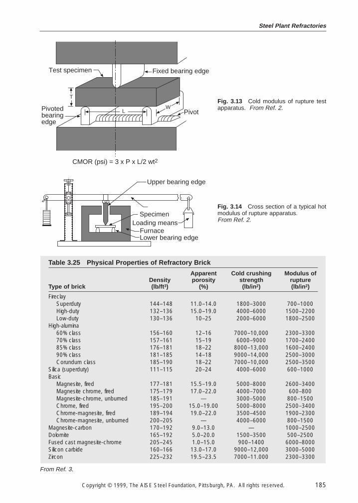
3.3.4 StrengthThe cold strength(s) of refractories arecommonly measured in either compres-sion, Fig. 3.12 or transversely in a modu-lus of rupture test, Fig. 3.13.
These cold strength values give somemeasure of the consistency of the refrac-tory product and its ability to functionduring shipment and installation.
Hot strength values are also determinedby similar procedures with the refractoryspecimen contained in a furnace whichmay also provide for a protective atmos-phere surrounding the specimen. Fig.3.14 shows the simplest hot modulus ofrupture apparatus.
Sphericalseat
Center ofspherical surface
Sphericalbearing block
Test specimenBedding material
Load
C.C.S. (psi) = load(lbs)/area(in2)** Area is cross section area (average) of sample
Fig. 3.12 Cold crushing strength test apparatus. From Ref. 2.
Steel Plant Refractories
Copyright © 1999, The AISE Steel Foundation, Pittsburgh, PA. All rights reserved. 185
Table 3.25 Physical Properties of Refractory Brick
Apparent Cold crushing Modulus ofDensity porosity strength rupture
Type of brick (lb/ft 3) (%) (lb/in 2) (lb/in 2)
FireclaySuperduty 144–148 11.0–14.0 1800–3000 700–1000High-duty 132–136 15.0–19.0 4000–6000 1500–2200Low-duty 130–136 10–25 2000–6000 1800–2500
High-alumina60% class 156–160 12–16 7000–10,000 2300–330070% class 157–161 15–19 6000–9000 1700–240085% class 176–181 18–22 8000–13,000 1600–240090% class 181–185 14–18 9000–14,000 2500–3000Corundum class 185–190 18–22 7000–10,000 2500–3500
Silica (superduty) 111–115 20–24 4000–6000 600–1000Basic
Magnesite, fired 177–181 15.5–19.0 5000–8000 2600–3400Magnesite chrome, fired 175–179 17.0–22.0 4000–7000 600–800Magnesite-chrome, unburned 185–191 — 3000–5000 800–1500Chrome, fired 195–200 15.0–19.00 5000–8000 2500–3400Chrome-magnesite, fired 189–194 19.0–22.0 3500–4500 1900–2300Chrome-magnesite, unburned 200–205 — 4000–6000 800–1500
Magnesite-carbon 170–192 9.0–13.0 — 1000–2500Dolomite 165–192 5.0–20.0 1500–3500 500–2500Fused cast magnesite-chrome 205–245 1.0–15.0 900–1400 6000–8000Silicon carbide 160–166 13.0–17.0 9000–12,000 3000–5000Zircon 225–232 19.5–23.5 7000–11.000 2300–3300
Test specimen Fixed bearing edge
Pivotedbearingedge
Pivot
T
LW
CMOR (psi) = 3 x P x L/2 wt2
Fig. 3.13 Cold modulus of rupture testapparatus. From Ref. 2.
Upper bearing edge
Lower bearing edgeFurnace
SpecimenLoading means
Fig. 3.14 Cross section of a typical hotmodulus of rupture apparatus. From Ref. 2.
From Ref. 3.
Ironmaking Volume
186 Copyright © 1999, The AISE Steel Foundation, Pittsburgh, PA. All rights reserved.
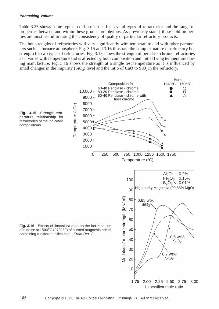
Table 3.25 shows some typical cold properties for several types of refractories and the range ofproperties between and within these groups are obvious. As previously stated, these cold proper-ties are most useful in rating the consistency of quality of particular refractory products.
The hot strengths of refractories will vary significantly with temperature and with other parame-ters such as furnace atmosphere. Fig. 3.15 and 3.16 illustrate the complex nature of refractory hotstrength for two types of refractories. Fig. 3.15 shows the strength of periclase-chrome refractoriesas it varies with temperature and is affected by both composition and initial firing temperature dur-ing manufacture. Fig. 3.16 shows the strength at a single test temperature as it is influenced bysmall changes in the impurity (SiO2) level and the ratio of CaO to SiO2 in the refractory.
Burn1540°C 1705°C
10,000
9000
8000
7000
6000
5000
4000
3000
2000
1000
Temperature (°C)
Tem
pera
ture
(kP
a)
0 250 500 750 1000 1250 1500 1750
Composition %60-40 Periclase - chrome80-20 Periclase - chrome60-40 Periclase - chrome with finer chrome
Fig. 3.15 Strength-tem-perature relationship forrefractories of the indicatedcompositions.
0.5 wt%SiO2
0.7 wt%SiO2
0.85 wt%SiO2
Al2O3 0.2%Fe2O3 0.15%B2O3 < 0.01%
High purity Magnesia (99.85% MgO)
100
90
80
70
60
50
40
30
20
10
Mod
ulus
of r
uptu
re s
tren
gth
(MN
/m2 )
1.75 2.00 2.25 2.50 2.75 3.00Lime/silica mole ratio
Fig. 3.16 Effects of lime/silica ratio on the hot modulusof rupture at 1500°C (2732°F) of burned magnesia brickscontaining a different silica level. From Ref. 2.
Steel Plant Refractories
Copyright © 1999, The AISE Steel Foundation, Pittsburgh, PA. All rights reserved. 187
3.3.5 Stress-Strain Behavior
When a refractory is subjected to a mechanical load, it will compress. This behavior may be quan-tified by the following equation:
ε 5 }s
E} (3.3.1)
where:
ε 5 strain (dimensionless),σ 5 stress psi (MPa),E 5 Modulus of elasticity, psi (MPa).
Strain is equal to the amount of compression divided by the original length.
ε 5 }D
L
L} (3.3.2)
Stress is the force applied per unit area.
s 5 }A
F} (3.3.3)
The modulus of elasticity, or Young’s Modulus, of a refractory is constant for a given material andtemperature.
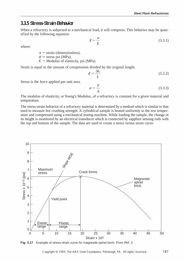
The stress-strain behavior of a refractory material is determined by a method which is similar to thatused to measure hot crushing strength. A cylindrical sample is heated uniformly to the test temper-ature and compressed using a mechanical testing machine. While loading the sample, the change inits height is monitored by an electrical transducer which is connected by sapphire sensing rods withthe top and bottom of the sample. The data are used to create a stress versus strain curve.
0 5 10 15 20 25 30 35 40 45 50
Maximumstress Crack forms
Yield point
Magnesitespinelbrick
Plasticrange
Elasticrange
Strain x 103
Slop
e M
OE
Str
ess
x 10
–3 (
psi)
10
9
8
7
6
5
4
3
2
1
0
Fig. 3.17 Example of stress-strain curve for magnesite-spinel brick. From Ref. 3.
Ironmaking Volume
188 Copyright © 1999, The AISE Steel Foundation, Pittsburgh, PA. All rights reserved.
Fig. 3.17 illustrates a typical stress-straincurve. The initial portion of the curve isusually linear and is called the elastic range.The slope of the curve over this range givesthe modulus of elasticity. The point atwhich the stress-strain curve becomes non-linear is called the yield point. Straining thematerial beyond this point results in perma-nent deformation; this portion of the curveis known as the plastic range. Furtherstraining of the material brings failure.Some materials do not show plastic behav-ior at certain temperatures, but instead failafter elastic straining. Modulus of elasticityvalues of a number of refractories areshown in Table 3.26.
An understanding of the stress-strain behavior of refractories at elevated temperatures is importantin nearly all applications. The shell or superstructure of a vessel usually acts to restrain the thermalexpansion of the lining. Proper lining design may require gaps in the lining (thermal expansionallowance) during installation to prevent catastrophic stress buildup in the lining during heating.However, the expansion allowance must also be designed to prevent instability of the lining. Theengineer, too, must be concerned with the stresses which the expanding refractories induce in thevessel shell or superstructure. Section 3.5 on the selection of refractories will further describeanalysis techniques for refractory behavior under stress.
3.3.6 Specific Heat
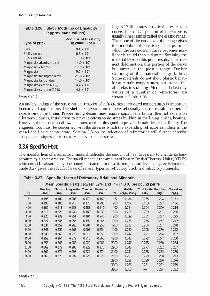
The specific heat of a refractory material indicates the amount of heat necessary to change its tem-perature by a given amount. The specific heat is the amount of heat in British Thermal Units (BTU’s)which must be absorbed by one pound of material to raise its temperature by one degree Fahrenheit.Table 3.27 gives the specific heats of several types of refractory brick and refractory minerals.
Table 3.27 Specific Heats of Refractory Brick and Minerals
Mean Specific Heats between 32°F, and T°F, in BTU per pound per °FFireclay Silica Magnesite Chrome Forsterite Mullite Cristobalite Periclase Corundum
T°F Brick Brick Brick Brick Brick T°F 3Al2O3•2SiO2 SiO2 MgO Al2O3
32 0.193 0.169 0.208 0.170 0.180 32 0.184 0.165 0.208 0.171200 0.199 0.188 0.219 0.176 0.200 200 0.192 0.183 0.227 0.196400 0.206 0.211 0.232 0.182 0.216 400 0.214 0.204 0.240 0.214600 0.212 0.229 0.242 0.188 0.230 600 0.223 0.239 0.251 0.226800 0.220 0.238 0.251 0.194 0.240 800 0.229 0.251 0.257 0.235
1000 0.227 0.246 0.258 0.199 0.246 1000 0.233 0.258 0.262 0.2421200 0.234 0.252 0.263 0.204 0.250 1200 0.237 0.264 0.267 0.2481400 0.241 0.256 0.268 0.208 0.254 1400 0.240 0.268 0.270 0.2521600 0.248 0.260 0.273 0.212 0.258 1600 0.242 0.271 0.274 0.2571800 0.253 0.264 0.278 0.216 0.262 1800 0.245 0.273 0.277 0.2602000 0.258 0.268 0.283 0.220 0.266 2000 0.247 0.275 0.280 0.2642200 0.262 0.272 0.288 0.222 0.270 2200 0.249 0.277 0.282 0.2672400 0.266 0.276 0.293 0.224 0.274 2400 0.251 0.278 0.285 0.2702600 0.269 0.279 0.297 0.226 0.278 2600 0.253 0.279 0.288 0.273
2800 0.255 0.280 0.290 0.2763000 0.256 0.281 0.292 0.2793200 0.258 — 0.294 0.282
Table 3.26 Static Modulus of Elasticity (approximate values)
Modulus of ElasticityType of brick at 2000°F (psi)
Silica 9.0 x 10⁵
50% alumina 6.9 x 10⁵
60% alumina 17.0 x 10⁵
Magnesite-alumina-spinel 14.0 x 10⁵
Magnesite-chrome 12.0 x 10⁵
Magnesite 9.3 x 10⁵
Magnesite-tar impregnated 21.0 x 10⁵
Magnesite-tar bonded 14.0 x 10⁵
Magnesite-carbon (20%) 4.4 x 10⁵
Magnesite-carbonn (15%) 4.0 x 10⁵
From Ref. 3.
From Ref. 3.
Steel Plant Refractories
Copyright © 1999, The AISE Steel Foundation, Pittsburgh, PA. All rights reserved. 189
The specific heat values for refractory materials are important in many applications because theamount of heat stored in the lining during heating is often significant. In furnaces which are cycled,large amounts of heat are alternately stored during heating stages and lost to the surroundings dur-ing cooling stages. Applications for which high specific heat is desirable include blast furnacestoves. Stoves are specifically designed to absorb and store heat from hot waste gases. The storedheat is subsequently used to preheat combustion air.
3.3.7 Emissivity
Emissivity is the relative power of a surface to emit heat by radiation. It is expressed as a fractionof the emissivity of an ideal black body. Such black body radiation is the maximum possible, butit is never achieved by actual materials. A good radiator is an equally good absorber of heat. Agood reflector, obviously, is a poor absorber, and consequently a poor radiator. A perfect reflec-tor, which also does not exist, would have an emissivity of zero. Materials do not radiate equallywell at all wavelengths. The ability to radiate at a particular wavelength is referred to as the mono-chromatic emissivity. Total emissivity refers to heat radiation over the entire spectrum of wave-lengths. The total emissivity of most refractories decreases somewhat with an increase intemperature.
Emissivities dictate the amount of heat which is radiated across a gap in a refractory structure. Theequation used to calculate this quantity is
Qr 5 s 1 2 (3.3.4)
where:
Qr 5 heat radiated across gap, Wm–2 (BTU hr–1 ft–2),σ 5 Stefan-Boltzmann constant, W/m–2 K–4 (BTU hr–1 ft–2 °R–4),
T1 5 temperature of hotter surface of gap, K (°R),T2 5 temperature of cooler surface of gap, K (°R),ε1 5 emissivity of hotter surface of gap, dimensionless,ε2 5 emissivity of cooler surface of gap, dimensionless.
In the above equation, the temperatures must be expressed using an absolute temperature scale. Thetemperature in Kelvins is K = °C + 273; the temperature in degrees Rankin is °R = °F + 460. TheStefan-Boltzmann constant is 5.670 × 10⁻⁹ Wm–2 K–4 (1.714 × 10⁻⁹ BTU hr–1 ft–2 R–4)
The emissivity of the outermost component of a vessel determines, to a large extent, the amountof heat radiated to the surroundings. The loss to the environment by unobstructed radiation isgiven by:
Qr 5 εs (T14 2 T2
4) (3.3.5)
where:
Qr 5 heat radiated to surroundings, Wm–2 (BTU hr–1 ft–2),σ 5 Stefan-Boltzmann constant, W/m–2 K–4 (BTU hr–1 ft–2 °R–4),ε 5 emissivity of outer surface, dimensionless,
T1 5 temperature of outer surface, K (°R),T2 5 temperature of surroundings, K (°R).
In most applications, the outer surface is a metallic shell such as carbon steel plate. the emissivityof the shell, in this case, is affected by the degree of oxidation. The emissivity tends to increase asthe amount of oxidation increases.
Emissivity values for a number of refractories and materials commonly used for shells are listed inTable 3.28
T14 2 T2
4
}}}εl1} 1 }ε2 2
11}
Ironmaking Volume
190 Copyright © 1999, The AISE Steel Foundation, Pittsburgh, PA. All rights reserved.
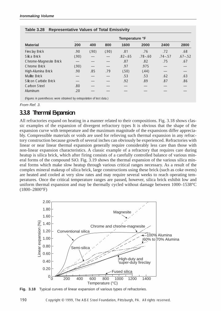
3.3.8 Thermal Expansion
All refractories expand on heating in a manner related to their compositions. Fig. 3.18 shows clas-sic examples of the expansion of divergent refractory types It is obvious that the shape of theexpansion curve with temperature and the maximum magnitude of the expansions differ apprecia-bly. Compressible materials or voids are used for relieving such thermal expansion in any refrac-tory construction because growth of several inches can obviously be experienced. Refractories withlinear or near linear thermal expansion generally require considerably less care than those withnon-linear expansion characteristics. A classic example of a refractory that requires care duringheatup is silica brick, which after firing consists of a carefully controlled balance of various min-eral forms of the compound SiO. Fig. 3.19 shows the thermal expansion of the various silica min-eral forms which make slow heatup through various critical ranges necessary. As a result of thecomplex mineral makeup of silica brick, large constructions using these brick (such as coke ovens)are heated and cooled at very slow rates and may require several weeks to reach operating tem-peratures. Once the critical temperature ranges are passed, however, silica brick exhibit low anduniform thermal expansion and may be thermally cycled without damage between 1000–1538°C(1800–2800°F)
Table 3.28 Representative Values of Total Emissivity
Temperature °F_________________________________________________________Material 200 400 800 1600 2000 2400 2800
Fireclay Brick .90 (.90) (.90) .81 .76 .72 .68Silica Brick (.90) — — .82–.65 .78–.60 .74–.57 .67–.52Chrome-Magnesite Brick — — — .87 .82 .75 .67Chrome Brick (.90) — — .97 .975 — —High-Alumina Brick .90 .85 .79 (.50) (.44) — —Mullite Brick — — — .53 .53 .62 .63Silicon Carbide Brick — — — .92 .89 .87 .86Carbon Steel .80 — — — — — —Aluminum .20 — — — — — —
(Figures in parentheses were obtained by extrapolation of test data.)
Temperature (°C)
Magnesite
Chrome and chrome-magnesite
100% Alumina60% to 70% Alumina
High-duty andsuper-duty fireclay
Fused silica
Conventional silica
Semi-silica
0 200 400 600 800 1000 1200 1400
2.00
1.80
1.60
1.40
1.20
1.00
0.80
0.60
0.40
0.20
0
Line
ar e
xpan
sion
(%
)
Fig. 3.18 Typical curves of linear expansion of various types of refractories.
From Ref. 3.
Steel Plant Refractories
Copyright © 1999, The AISE Steel Foundation, Pittsburgh, PA. All rights reserved. 191
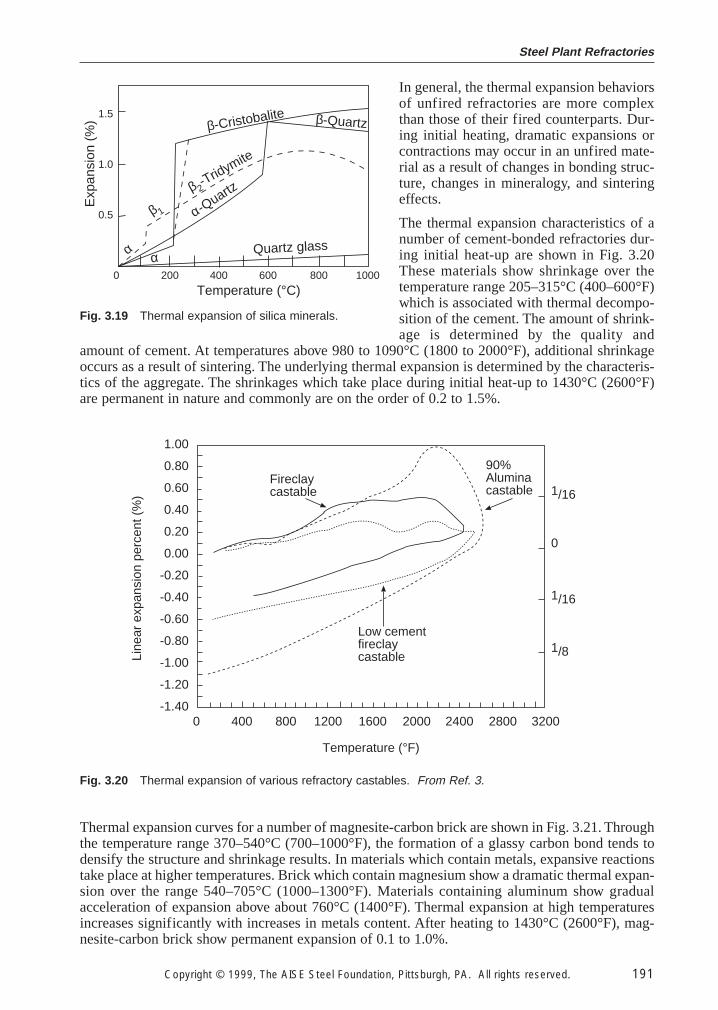
In general, the thermal expansion behaviorsof unfired refractories are more complexthan those of their fired counterparts. Dur-ing initial heating, dramatic expansions orcontractions may occur in an unfired mate-rial as a result of changes in bonding struc-ture, changes in mineralogy, and sinteringeffects.
The thermal expansion characteristics of anumber of cement-bonded refractories dur-ing initial heat-up are shown in Fig. 3.20These materials show shrinkage over thetemperature range 205–315°C (400–600°F)which is associated with thermal decompo-sition of the cement. The amount of shrink-age is determined by the quality and
amount of cement. At temperatures above 980 to 1090°C (1800 to 2000°F), additional shrinkageoccurs as a result of sintering. The underlying thermal expansion is determined by the characteris-tics of the aggregate. The shrinkages which take place during initial heat-up to 1430°C (2600°F)are permanent in nature and commonly are on the order of 0.2 to 1.5%.
Line
ar e
xpan
sion
per
cent
(%
)
1.00
0.80
0.60
0.40
0.20
0.00
-0.20
-0.40
-0.60
-0.80
-1.00
-1.20
-1.400 400 800 1200 1600 2000 2400 2800 3200
1/16
0
1/16
1/8
Fireclaycastable
90%Aluminacastable
Low cementfireclaycastable
Temperature (°F)
Fig. 3.20 Thermal expansion of various refractory castables. From Ref. 3.
Exp
ansi
on (
%) 1.5
1.0
0.5
β-Cristobalite
β 2-Tridymite
Quartz glass
0 200 400 600 800 1000
Temperature (°C)
α-Quartz
β 1
β-Quartz
α α
Fig. 3.19 Thermal expansion of silica minerals.
Thermal expansion curves for a number of magnesite-carbon brick are shown in Fig. 3.21. Throughthe temperature range 370–540°C (700–1000°F), the formation of a glassy carbon bond tends todensify the structure and shrinkage results. In materials which contain metals, expansive reactionstake place at higher temperatures. Brick which contain magnesium show a dramatic thermal expan-sion over the range 540–705°C (1000–1300°F). Materials containing aluminum show gradualacceleration of expansion above about 760°C (1400°F). Thermal expansion at high temperaturesincreases significantly with increases in metals content. After heating to 1430°C (2600°F), mag-nesite-carbon brick show permanent expansion of 0.1 to 1.0%.
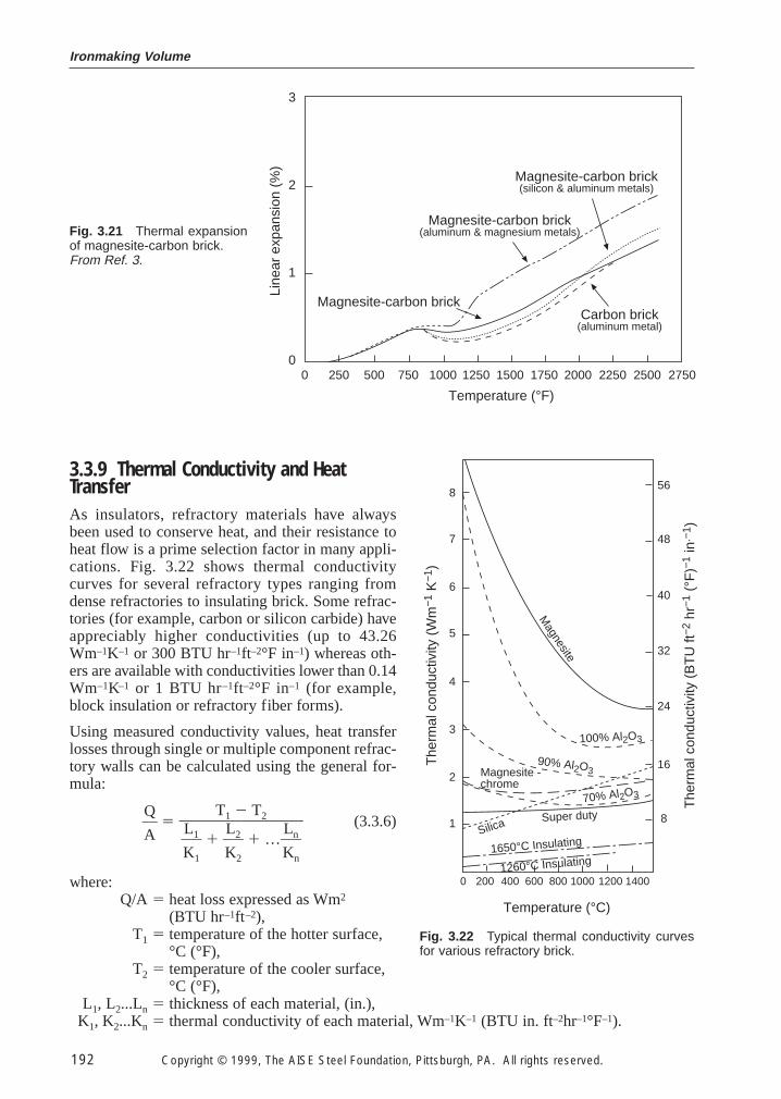
Ironmaking Volume
192 Copyright © 1999, The AISE Steel Foundation, Pittsburgh, PA. All rights reserved.
3.3.9 Thermal Conductivity and Heat TransferAs insulators, refractory materials have alwaysbeen used to conserve heat, and their resistance toheat flow is a prime selection factor in many appli-cations. Fig. 3.22 shows thermal conductivitycurves for several refractory types ranging fromdense refractories to insulating brick. Some refrac-tories (for example, carbon or silicon carbide) haveappreciably higher conductivities (up to 43.26Wm–1K–1 or 300 BTU hr–1ft–2°F in–1) whereas oth-ers are available with conductivities lower than 0.14Wm–1K–1 or 1 BTU hr–1ft–2°F in–1 (for example,block insulation or refractory fiber forms).
Using measured conductivity values, heat transferlosses through single or multiple component refrac-tory walls can be calculated using the general for-mula:
}Q
A} 5 (3.3.6)
where:Q/A 5 heat loss expressed as Wm2
(BTU hr–1ft–2),T1 5 temperature of the hotter surface,
°C (°F),T2 5 temperature of the cooler surface,
°C (°F),L1, L2...Ln 5 thickness of each material, (in.),
K1, K2...Kn 5 thermal conductivity of each material, Wm–1K–1 (BTU in. ft–2hr–1°F–1).
T1 2 T2}}}K
L1
1
} 1 }K
L2
2
} 1 …}K
Ln
n
}
0 250 500 750 1000 1250 1500 1750 2000 2250 2500 2750
3
2
1
0
Line
ar e
xpan
sion
(%
)
Temperature (°F)
Magnesite-carbon brick(silicon & aluminum metals)
Magnesite-carbon brick(aluminum & magnesium metals)
Magnesite-carbon brickCarbon brick
(aluminum metal)
Fig. 3.21 Thermal expansionof magnesite-carbon brick.From Ref. 3.
The
rmal
con
duct
ivity
(W
m−1
K−1
)
8
7
6
5
4
3
2
1
0 200 400 600 800 1000 1200 1400
Magnesite
100% Al2O3
90% Al2O3Magnesite -chrome
Silica Super duty70% Al2O3
1650°C Insulating
Temperature (°C)
The
rmal
con
duct
ivity
(B
TU
ft−2
hr−
1 (°
F)−
1 in
.−1 )
56
48
40
32
24
16
8
1260°C Insulating
Fig. 3.22 Typical thermal conductivity curvesfor various refractory brick.
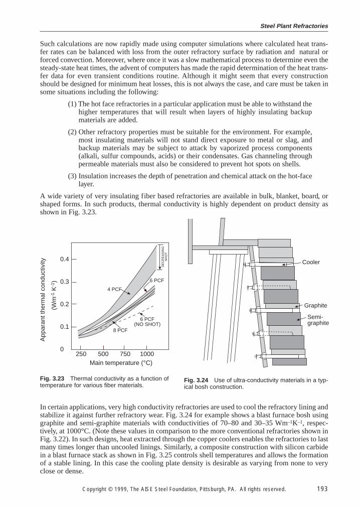
Steel Plant Refractories
Copyright © 1999, The AISE Steel Foundation, Pittsburgh, PA. All rights reserved. 193
Such calculations are now rapidly made using computer simulations where calculated heat trans-fer rates can be balanced with loss from the outer refractory surface by radiation and natural orforced convection. Moreover, where once it was a slow mathematical process to determine even thesteady-state heat times, the advent of computers has made the rapid determination of the heat trans-fer data for even transient conditions routine. Although it might seem that every constructionshould be designed for minimum heat losses, this is not always the case, and care must be taken insome situations including the following:
(1) The hot face refractories in a particular application must be able to withstand thehigher temperatures that will result when layers of highly insulating backupmaterials are added.
(2) Other refractory properties must be suitable for the environment. For example,most insulating materials will not stand direct exposure to metal or slag, andbackup materials may be subject to attack by vaporized process components(alkali, sulfur compounds, acids) or their condensates. Gas channeling throughpermeable materials must also be considered to prevent hot spots on shells.
(3) Insulation increases the depth of penetration and chemical attack on the hot-facelayer.
A wide variety of very insulating fiber based refractories are available in bulk, blanket, board, orshaped forms. In such products, thermal conductivity is highly dependent on product density asshown in Fig. 3.23.
(Wm
-1 K
-1)
0.4
0.3
0.2
0.1
0250 500 750 1000
4 PCF
6 PCF
8 PCF
6 PCF(NO SHOT)
DE
CR
EA
SIN
GS
HO
T
Main temperature (°C)
App
aran
t the
rmal
con
duct
ivity
Fig. 3.23 Thermal conductivity as a function oftemperature for various fiber materials.
Semi-graphite
Cooler
Graphite
Fig. 3.24 Use of ultra-conductivity materials in a typ-ical bosh construction.
In certain applications, very high conductivity refractories are used to cool the refractory lining andstabilize it against further refractory wear. Fig. 3.24 for example shows a blast furnace bosh usinggraphite and semi-graphite materials with conductivities of 70–80 and 30–35 Wm–1K–1, respec-tively, at 1000°C. (Note these values in comparison to the more conventional refractories shown inFig. 3.22). In such designs, heat extracted through the copper coolers enables the refractories to lastmany times longer than uncooled linings. Similarly, a composite construction with silicon carbidein a blast furnace stack as shown in Fig. 3.25 controls shell temperatures and allows the formationof a stable lining. In this case the cooling plate density is desirable as varying from none to veryclose or dense.
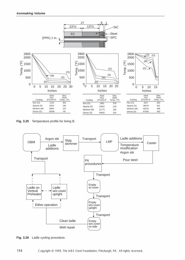
Ironmaking Volume
194 Copyright © 1999, The AISE Steel Foundation, Pittsburgh, PA. All rights reserved.
Tem
p. (
°F)
0 5 10 15
Heat MaxFlux Shell
Cooling BTU/Hr-ft2 Temp. (°F)
Non (O) 3027 600Sparse (S) 28476 541Medium (M) 46232 496Dense (D) 97693 360
0 5 10 15 20 25 30
Heat MaxFlux Shell
Cooling BTU/Hr-ft2 Temp. (°F)
Non (O) 1104 303Sparse (S) 6202 160Medium (M) 8993 124Dense (D) 15090 89
0 5 10 15 20 25
Heat MaxFlux Shell
Cooling STU/Hr-ft2 Temp. (°F)
Non (O) 1481 376Sparse (S) 13641 218Medium (M) 21771 165Dense (D) 44591 104
(PPK) 1 in.Steel
27131/2 131/2
8 1SiC
FCSPC
(O)
(S)(M)
(D)
28002000
1500
1000
500
0
Tem
p. (
°F)
Inches
28002000
1500
1000
500
0
Inches
(D)
(M)
(O)(S)28002000
1500
1000
500
0
Tem
p. (
°F)
Inches
(O)
(S)(M)
(D)
Fig. 3.25 Temperature profile for lining B.
OBMArgon stir
Ladleadditions
Slagskimmer
LMF Caster
Pitprocedures
Transport
Transport
Emptyw/ cover
Emptyw/o coverupright
Transport
Emptyw/o coveron side
Clean ladle
Well repair
Either operation
Ladle onVerticalPreheater
Ladlew/o coverupright
Transport
Transport Ladle additions
TemperaturemodificationArgon stir
Pour steel
Fig. 3.26 Ladle cycling procedure.
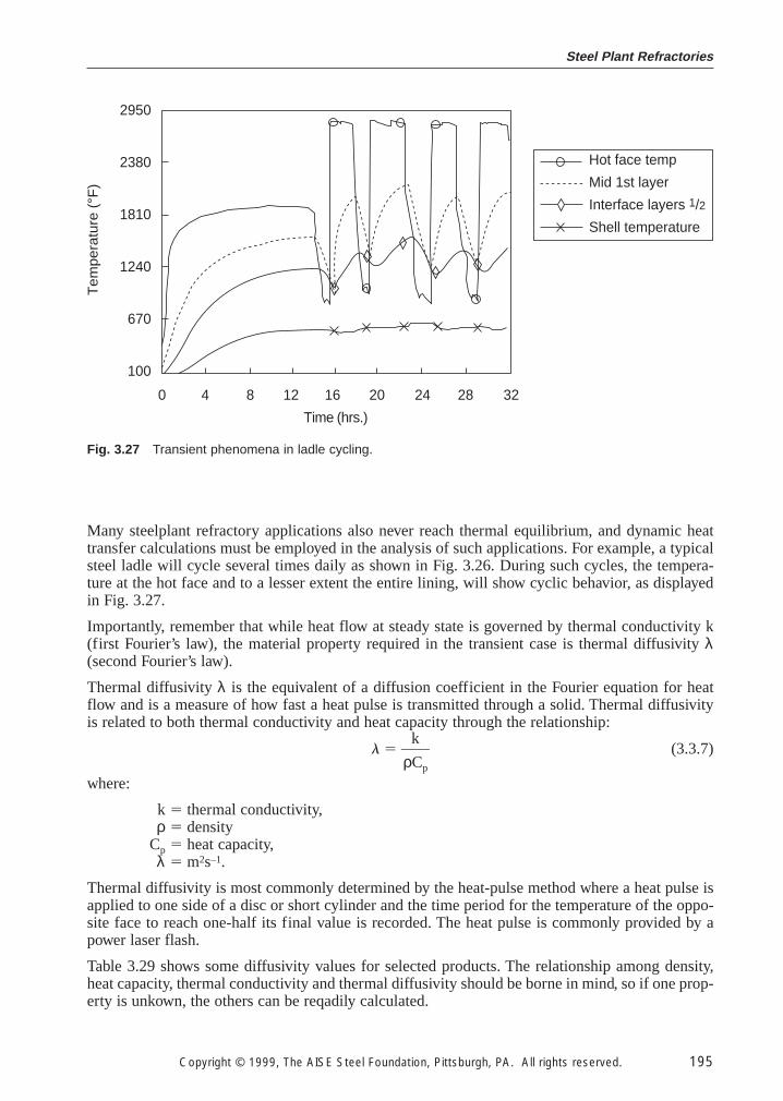
Steel Plant Refractories
Copyright © 1999, The AISE Steel Foundation, Pittsburgh, PA. All rights reserved. 195
Many steelplant refractory applications also never reach thermal equilibrium, and dynamic heattransfer calculations must be employed in the analysis of such applications. For example, a typicalsteel ladle will cycle several times daily as shown in Fig. 3.26. During such cycles, the tempera-ture at the hot face and to a lesser extent the entire lining, will show cyclic behavior, as displayedin Fig. 3.27.
Importantly, remember that while heat flow at steady state is governed by thermal conductivity k(first Fourier’s law), the material property required in the transient case is thermal diffusivity λ(second Fourier’s law).
Thermal diffusivity λ is the equivalent of a diffusion coefficient in the Fourier equation for heatflow and is a measure of how fast a heat pulse is transmitted through a solid. Thermal diffusivityis related to both thermal conductivity and heat capacity through the relationship:
l 5 }ρ
k
Cp
} (3.3.7)
where:
k 5 thermal conductivity,ρ 5 density
Cp 5 heat capacity,λ 5 m2s–1.
Thermal diffusivity is most commonly determined by the heat-pulse method where a heat pulse isapplied to one side of a disc or short cylinder and the time period for the temperature of the oppo-site face to reach one-half its final value is recorded. The heat pulse is commonly provided by apower laser flash.
Table 3.29 shows some diffusivity values for selected products. The relationship among density,heat capacity, thermal conductivity and thermal diffusivity should be borne in mind, so if one prop-erty is unkown, the others can be reqadily calculated.
2950
2380
1810
1240
670
100
0 4 8 12 16 20 24 28 32
Time (hrs.)
Tem
pera
ture
(°F
)
Hot face temp
Mid 1st layer
Interface layers 1/2
Shell temperature
Fig. 3.27 Transient phenomena in ladle cycling.
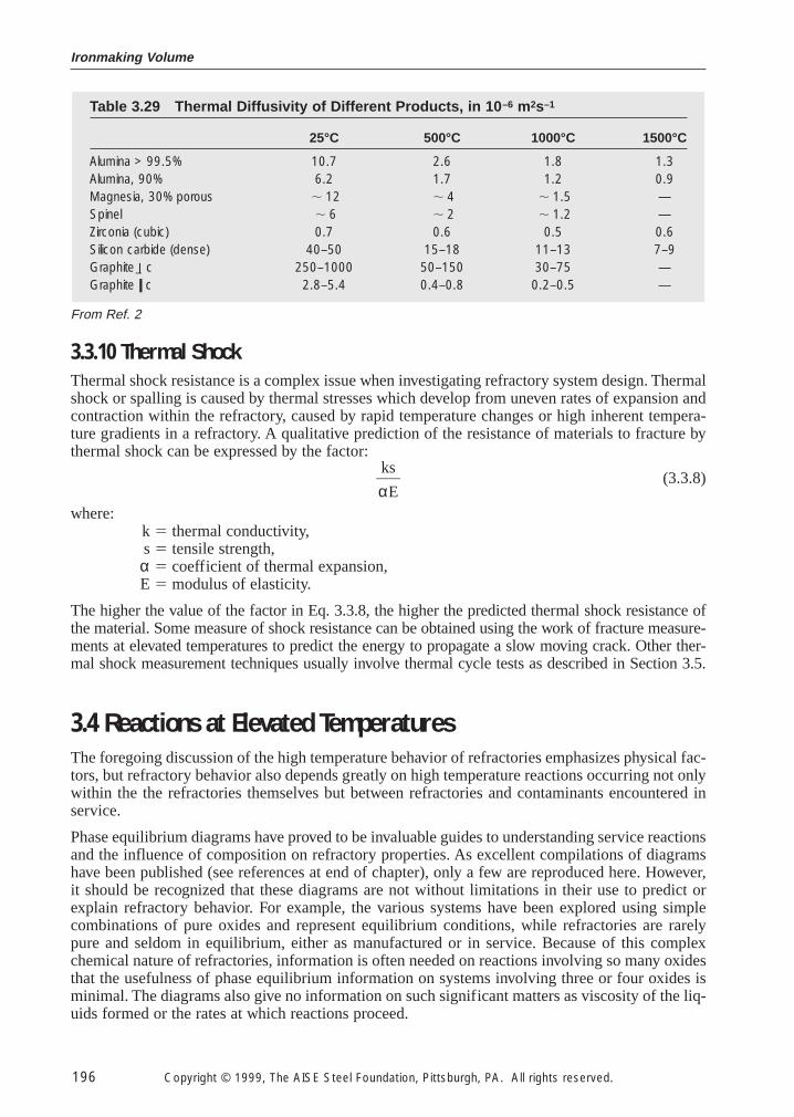
Ironmaking Volume
196 Copyright © 1999, The AISE Steel Foundation, Pittsburgh, PA. All rights reserved.
3.3.10 Thermal Shock
Thermal shock resistance is a complex issue when investigating refractory system design. Thermalshock or spalling is caused by thermal stresses which develop from uneven rates of expansion andcontraction within the refractory, caused by rapid temperature changes or high inherent tempera-ture gradients in a refractory. A qualitative prediction of the resistance of materials to fracture bythermal shock can be expressed by the factor:
}αk
E
s} (3.3.8)
where:k 5 thermal conductivity,s 5 tensile strength,α 5 coefficient of thermal expansion,E 5 modulus of elasticity.
The higher the value of the factor in Eq. 3.3.8, the higher the predicted thermal shock resistance ofthe material. Some measure of shock resistance can be obtained using the work of fracture measure-ments at elevated temperatures to predict the energy to propagate a slow moving crack. Other ther-mal shock measurement techniques usually involve thermal cycle tests as described in Section 3.5.
3.4 Reactions at Elevated Temperatures
The foregoing discussion of the high temperature behavior of refractories emphasizes physical fac-tors, but refractory behavior also depends greatly on high temperature reactions occurring not onlywithin the the refractories themselves but between refractories and contaminants encountered inservice.
Phase equilibrium diagrams have proved to be invaluable guides to understanding service reactionsand the influence of composition on refractory properties. As excellent compilations of diagramshave been published (see references at end of chapter), only a few are reproduced here. However,it should be recognized that these diagrams are not without limitations in their use to predict orexplain refractory behavior. For example, the various systems have been explored using simplecombinations of pure oxides and represent equilibrium conditions, while refractories are rarelypure and seldom in equilibrium, either as manufactured or in service. Because of this complexchemical nature of refractories, information is often needed on reactions involving so many oxidesthat the usefulness of phase equilibrium information on systems involving three or four oxides isminimal. The diagrams also give no information on such significant matters as viscosity of the liq-uids formed or the rates at which reactions proceed.
Table 3.29 Thermal Diffusivity of Different Products, in 10 –6 m2s–1
25°C 500°C 1000°C 1500°C
Alumina > 99.5% 10.7 2.6 1.8 1.3Alumina, 90% 6.2 1.7 1.2 0.9Magnesia, 30% porous , 12 , 4 , 1.5 —Spinel , 6 , 2 , 1.2 —Zirconia (cubic) 0.7 0.6 0.5 0.6Silicon carbide (dense) 40–50 15–18 11–13 7–9Graphite l_ c 250–1000 50–150 30–75 —Graphite ll c 2.8–5.4 0.4–0.8 0.2–0.5 —
From Ref. 2
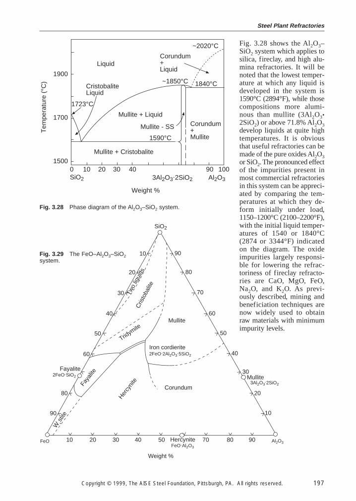
Steel Plant Refractories
Copyright © 1999, The AISE Steel Foundation, Pittsburgh, PA. All rights reserved. 197
0 10 20 30 40 90 100
1900
1700
1500
~2020°CCorundum+Liquid
~1850°C 1840°C
Liquid
CristobaliteLiquid
1723°C
1590°C
Corundum+Mullite
Al2O3SiO2
Tem
pera
ture
(°C
)
Weight %
Mullite + Liquid
Mullite - SS
Mullite + Cristobalite
3Al2O3.2SiO2
Fig. 3.28 Phase diagram of the Al2O3–SiO2 system.
10 20 30 40 50 70 80 90
Weight %
90
80
70
60
50
40
30
20
1090
80
60
50
40
30
20
10
Corundum
Hercy
nite
Mullite
Cris
toba
lite
Tridym
ite
Faya
lite
W¸s
tite
Fayalite
Two
liqui
ds
Mullite
FeO Al2O3HercyniteFeO.Al2O3
3Al2O3.2SiO2
2FeO.2Al2O3.5SiO2
Iron cordierite
2FeO.SiO2
SiO2
Fig. 3.29 The FeO–Al2O3–SiO2system.
Fig. 3.28 shows the Al2O3–SiO2 system which applies tosilica, fireclay, and high alu-mina refractories. It will benoted that the lowest temper-ature at which any liquid isdeveloped in the system is1590°C (2894°F), while thosecompositions more alumi-nous than mullite (3Al2O3•2SiO2) or above 71.8% Al2O3develop liquids at quite hightemperatures. It is obviousthat useful refractories can bemade of the pure oxides Al2O3or SiO2. The pronounced effectof the impurities present inmost commercial refractoriesin this system can be appreci-ated by comparing the tem-peratures at which they de-form initially under load,1150–1200°C (2100–2200°F),with the initial liquid temper-atures of 1540 or 1840°C(2874 or 3344°F) indicatedon the diagram. The oxideimpurities largely responsi-ble for lowering the refrac-toriness of fireclay refracto-ries are CaO, MgO, FeO,Na2O, and K2O. As previ-ously described, mining andbeneficiation techniques arenow widely used to obtainraw materials with minimumimpurity levels.
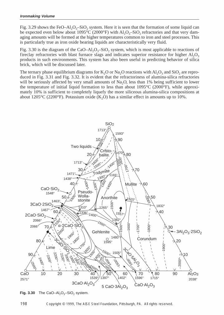
Ironmaking Volume
198 Copyright © 1999, The AISE Steel Foundation, Pittsburgh, PA. All rights reserved.
Fig. 3.29 shows the FeO–Al2O3–SiO2 system. Here it is seen that the formation of some liquid canbe expected even below about 1095°C (2000°F) with Al2O3–SiO2 refractories and that very dam-aging amounts will be formed at the higher temperatures common to iron and steel processes. Thisis particularly true as iron oxide bearing liquids are characteristically very fluid.
Fig. 3.30 is the diagram of the CaO–Al2O3–SiO2 system, which is most applicable to reactions offireclay refractories with blast furnace slags and indicates superior resistance for higher Al2O3products in such environments. This system has also been useful in predicting behavior of silicabrick, which will be discussed later.
The ternary phase equilibrium diagrams for K2O or Na2O reactions with Al2O3 and SiO2 are repro-duced in Fig. 3.31 and Fig. 3.32. It is evident that the refractoriness of alumina-silica refractorieswill be seriously affected by very small amounts of Na2O, less than 1% being sufficient to lowerthe temperature of initial liquid formation to less than about 1095°C (2000°F), while approxi-mately 10% is sufficient to completely liquefy the more siliceous alumina-silica compositions atabout 1205°C (2200°F). Potassium oxide (K2O) has a similar effect in amounts up to 10%.
CaO 10 20 30 40 50 60 70 80 90 Al2O3
2571° 2038°
SiO2
3Al2O3.2SiO2
5 CaO.3Al2O3
1713°
20
10
1713°
Two liquids
301471°
40
50
60
70
80
90
90
80
70
60
50
40
30
20
10
Anorthite
1500
°
1382°
1400
°
1300
°
1165°
1557°
1265°
CaO.SiO2
3CaO.2SiO2
2CaO.SiO2
3CaO.Al2O3 CaO.Al2O3
3CaO .5Al2 O3
1539° 1397° 1402° 1596° 1715°
1595°
1505°
1336° 1400°
1500°
Gehlenite1480°
1500°
1500
°
1548°
1463°
1467°
2066°
2066°
1600
°1700
°1800
°1900
°2000
°
2100
°
α-2CaO.SiO2
1593°
2500°2400°
2300°2200°2100°2000°
1800°1700°
1600°
1900°
1500°1405°
1335° 2000
°
1900
°
1800
°
1700
°
1600
°
1500
°
1832°
1515°
1800
°
1700
°1600
°15
00°
1300°
1400°
Tridymite1500°1600
°
1700
°
1438°
1500
°14
00°
1600
°
Corundum
Mullite
Cristo-balite
Pseudo-Wolla-stonite
Lime
1310°
1500
°
1300
°
1400
°
1470°
β
β
1400
°
3CaO .SiO2
Fig. 3.30 The CaO–Al2O3–SiO2 system.
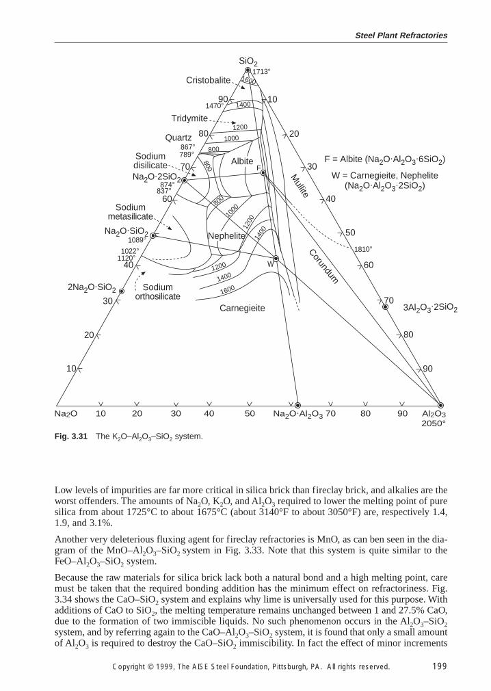
Steel Plant Refractories
Copyright © 1999, The AISE Steel Foundation, Pittsburgh, PA. All rights reserved. 199
Low levels of impurities are far more critical in silica brick than fireclay brick, and alkalies are theworst offenders. The amounts of Na2O, K2O, and Al2O3 required to lower the melting point of puresilica from about 1725°C to about 1675°C (about 3140°F to about 3050°F) are, respectively 1.4,1.9, and 3.1%.
Another very deleterious fluxing agent for fireclay refractories is MnO, as can ben seen in the dia-gram of the MnO–Al2O3–SiO2 system in Fig. 3.33. Note that this system is quite similar to theFeO–Al2O3–SiO2 system.
Because the raw materials for silica brick lack both a natural bond and a high melting point, caremust be taken that the required bonding addition has the minimum effect on refractoriness. Fig.3.34 shows the CaO–SiO2 system and explains why lime is universally used for this purpose. Withadditions of CaO to SiO2, the melting temperature remains unchanged between 1 and 27.5% CaO,due to the formation of two immiscible liquids. No such phenomenon occurs in the Al2O3–SiO2system, and by referring again to the CaO–Al2O3–SiO2 system, it is found that only a small amountof Al2O3 is required to destroy the CaO–SiO2 immiscibility. In fact the effect of minor increments
Na2O 10 20 30 40 50 Na2O.Al2O3 70 80 90 Al2O32050°
3Al2O3.2SiO2
SiO2
10
Cristobalite
Tridymite
Quartz
Sodiumdisilicate
Sodiummetasilicate
Sodiumorthosilicate
Corundum
Mullite
Carnegieite
80
40
60
60
20
30
40
50
70
80
90
1090
1600
1400
1200
1000
800
800
1000
1200
1400
800
W1200
1400
1600
1470°
867°789°
70Na2O.2SiO2
1810°
1713°
F
874°837°
1089°1022°
1120°
F = Albite (Na2O.Al2O3.6SiO2)
W = Carnegieite, Nephelite(Na2O.Al2O3
.2SiO2)
30
20
Na2O.SiO2
2Na2O.SiO2
Albite
Nephelite
Fig. 3.31 The K2O–Al2O3–SiO2 system.
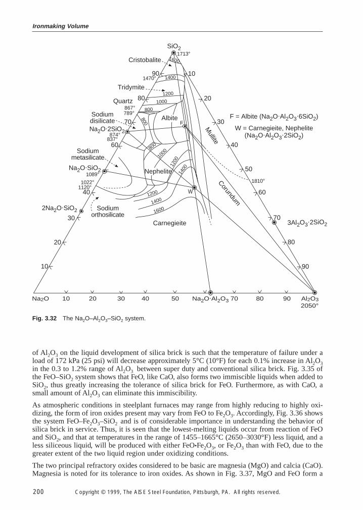
Ironmaking Volume
200 Copyright © 1999, The AISE Steel Foundation, Pittsburgh, PA. All rights reserved.
of Al2O3 on the liquid development of silica brick is such that the temperature of failure under aload of 172 kPa (25 psi) will decrease approximately 5°C (10°F) for each 0.1% increase in Al2O3in the 0.3 to 1.2% range of Al2O3 between super duty and conventional silica brick. Fig. 3.35 ofthe FeO–SiO2 system shows that FeO, like CaO, also forms two immiscible liquids when added toSiO2, thus greatly increasing the tolerance of silica brick for FeO. Furthermore, as with CaO, asmall amount of Al2O3 can eliminate this immiscibility.
As atmospheric conditions in steelplant furnaces may range from highly reducing to highly oxi-dizing, the form of iron oxides present may vary from FeO to Fe2O3. Accordingly, Fig. 3.36 showsthe system FeO–Fe2O3–SiO2 and is of considerable importance in understanding the behavior ofsilica brick in service. Thus, it is seen that the lowest-melting liquids occur from reaction of FeOand SiO2, and that at temperatures in the range of 1455–1665°C (2650–3030°F) less liquid, and aless siliceous liquid, will be produced with either FeO•Fe2O3, or Fe2O3 than with FeO, due to thegreater extent of the two liquid region under oxidizing conditions.
The two principal refractory oxides considered to be basic are magnesia (MgO) and calcia (CaO).Magnesia is noted for its tolerance to iron oxides. As shown in Fig. 3.37, MgO and FeO form a
Na2O 10 20 30 40 50 Na2O.Al2O3 70 80 90 Al2O32050°
3Al2O3.2SiO2
SiO2
10
Cristobalite
Tridymite
Quartz
Sodiumdisilicate
Sodiummetasilicate
Sodiumorthosilicate
Corundum
Mullite
Carnegieite
80
40
60
60
20
30
40
50
70
80
90
1090
1600
1400
1200
1000
800
800
1000
1200
1400
800
W1200
1400
1600
1470°
867°789°
70Na2O.2SiO2
1810°
1713°
F
874°837°
1089°1022°
1120°
F = Albite (Na2O.Al2O3.6SiO2)
W = Carnegieite, Nephelite(Na2O.Al2O3
.2SiO2)
30
20
Na2O.SiO2
2Na2O.SiO2
Albite
Nephelite
Fig. 3.32 The Na2O–Al2O3–SiO2 system.
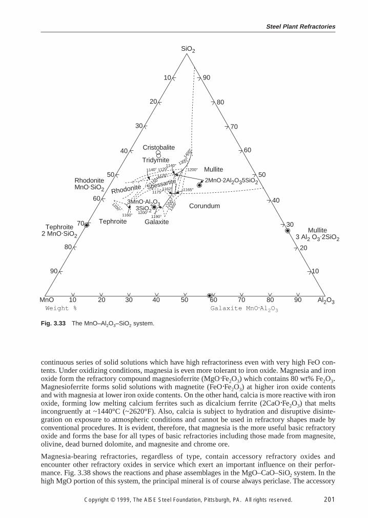
Steel Plant Refractories
Copyright © 1999, The AISE Steel Foundation, Pittsburgh, PA. All rights reserved. 201
continuous series of solid solutions which have high refractoriness even with very high FeO con-tents. Under oxidizing conditions, magnesia is even more tolerant to iron oxide. Magnesia and ironoxide form the refractory compound magnesioferrite (MgO·Fe2O3) which contains 80 wt% Fe2O3.Magnesioferrite forms solid solutions with magnetite (FeO·Fe2O3) at higher iron oxide contentsand with magnesia at lower iron oxide contents. On the other hand, calcia is more reactive with ironoxide, forming low melting calcium ferrites such as dicalcium ferrite (2CaO·Fe2O3) that meltsincongruently at ~1440°C (~2620°F). Also, calcia is subject to hydration and disruptive disinte-gration on exposure to atmospheric conditions and cannot be used in refractory shapes made byconventional procedures. It is evident, therefore, that magnesia is the more useful basic refractoryoxide and forms the base for all types of basic refractories including those made from magnesite,olivine, dead burned dolomite, and magnesite and chrome ore.
Magnesia-bearing refractories, regardless of type, contain accessory refractory oxides andencounter other refractory oxides in service which exert an important influence on their perfor-mance. Fig. 3.38 shows the reactions and phase assemblages in the MgO–CaO–SiO2 system. In thehigh MgO portion of this system, the principal mineral is of course always periclase. The accessory
MnO 10 20 30 40 50 60 70 80 90 Al2O3
SiO2
RhodoniteMnO.SiO2
Tephroite2 MnO.SiO2
Mullite3 Al2 O3
.2SiO2
90
80
70
60
50
40
30
20
1090
80
70
60
50
40
30
20
10
Weight % Galaxite MnO .Al 2O3
Cristobalite
Mullite
Corundum
Tephroite Galaxite
Tridymite
3MnO.Al2O33SiO2
2MnO.2Al2O35SiO2
1140° 1120°1140° 1300°1
400°
1200°
1165°
1190°1200°
1160°
1200°
1175°
1150°1175°
1300
°
1200
°
1162°Spessartite
Rhodonite
Fig. 3.33 The MnO–Al2O3–SiO2 system.
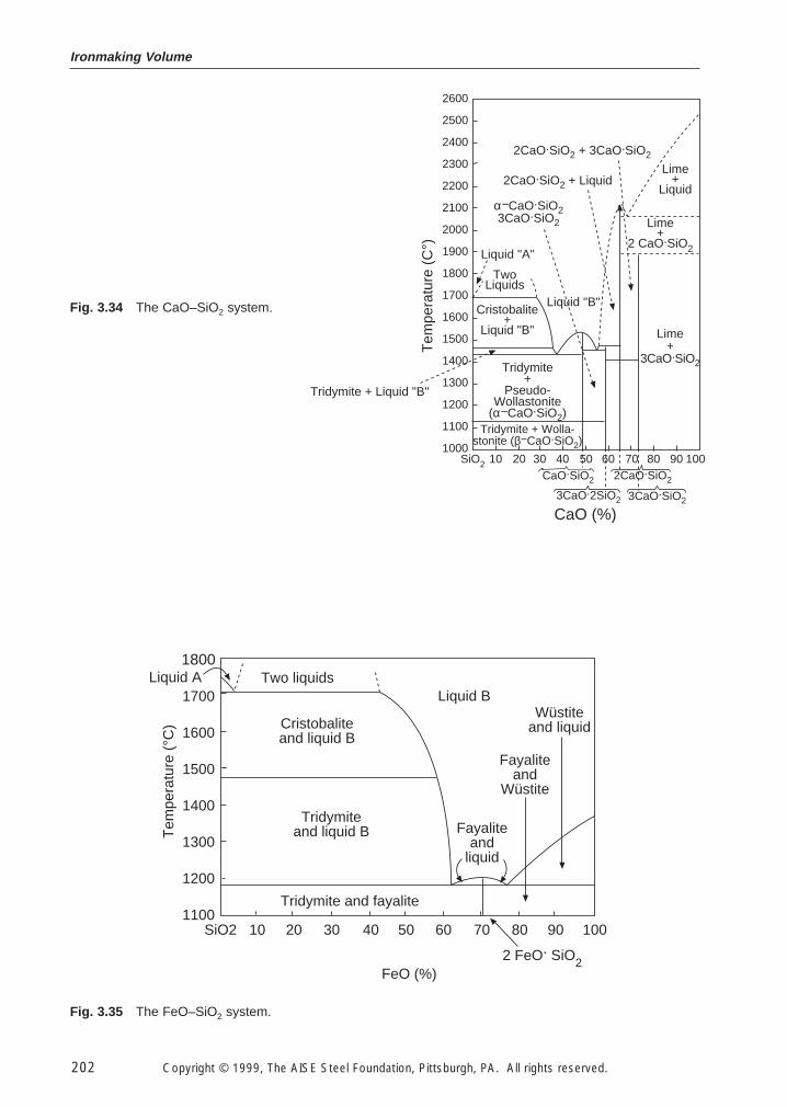
Ironmaking Volume
202 Copyright © 1999, The AISE Steel Foundation, Pittsburgh, PA. All rights reserved.
2600
2500
2400
2300
2200
2100
2000
1900
1800
1700
1600
1500
1400
1300
1200
1100
1000SiO2 10 20 30 40 50 60 70 80 90 100
Tem
pera
ture
(C
°)
Lime+
Liquid
Lime+
2 CaO.SiO2Liquid "A"
TwoLiquids
Liquid "B"Cristobalite
+Liquid "B"
Tridymite+
Pseudo-Wollastonite
(α−CaO.SiO2)Tridymite + Wolla-
stonite (β−CaO.SiO2)
Lime+
3CaO.SiO2
2CaO.SiO2 + Liquid
2CaO.SiO2 + 3CaO.SiO2
α−CaO.SiO23CaO.SiO2
2CaO.SiO2
3CaO.2SiO2 3CaO.SiO2
CaO (%)
Tridymite + Liquid "B"
CaO.SiO2
Fig. 3.34 The CaO–SiO2 system.
Two liquids
Cristobaliteand liquid B
Tridymiteand liquid B
Liquid BLiquid A
Tem
pera
ture
(°C
)
Wüstiteand liquid
Fayaliteand
liquid
Fayaliteand
Wüstite
Tridymite and fayalite
FeO (%)2 FeO. SiO2
1800
1700
1600
1500
1400
1300
1200
1100SiO2 10 20 30 40 50 60 70 80 90 100
Fig. 3.35 The FeO–SiO2 system.
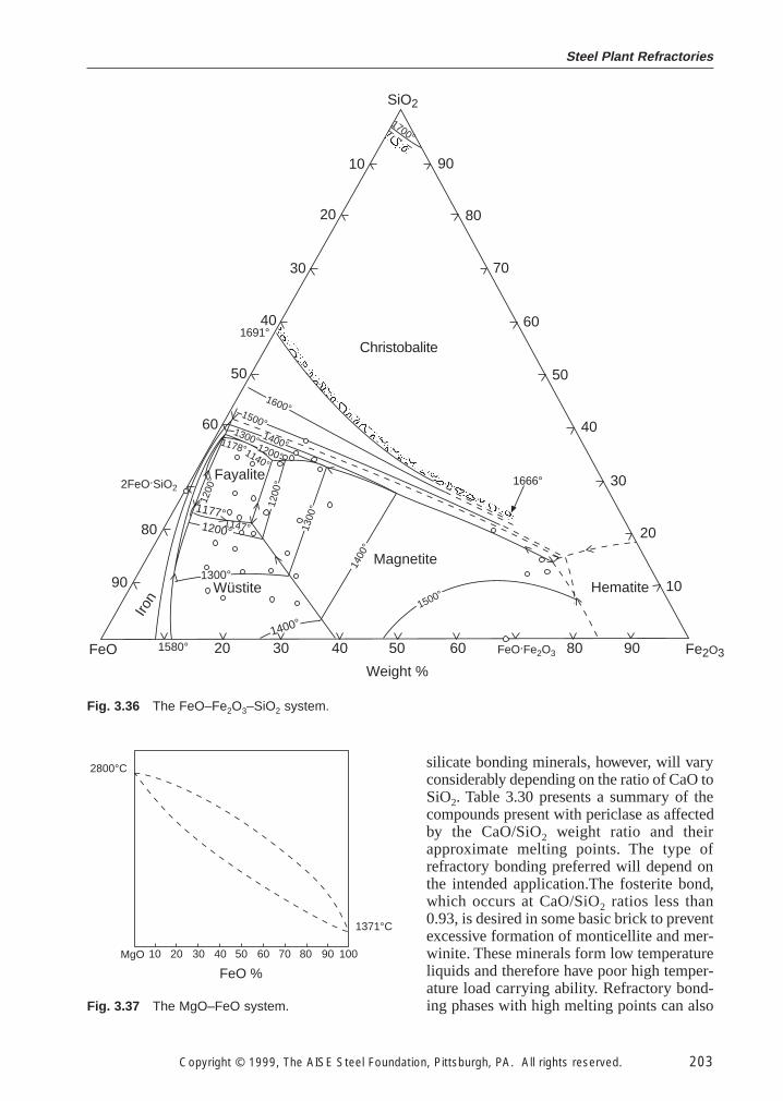
silicate bonding minerals, however, will varyconsiderably depending on the ratio of CaO toSiO2. Table 3.30 presents a summary of thecompounds present with periclase as affectedby the CaO/SiO2 weight ratio and theirapproximate melting points. The type ofrefractory bonding preferred will depend onthe intended application.The fosterite bond,which occurs at CaO/SiO2 ratios less than0.93, is desired in some basic brick to preventexcessive formation of monticellite and mer-winite. These minerals form low temperatureliquids and therefore have poor high temper-ature load carrying ability. Refractory bond-ing phases with high melting points can also
Steel Plant Refractories
Copyright © 1999, The AISE Steel Foundation, Pittsburgh, PA. All rights reserved. 203
20 30 40 50 60 80 90
90
80
70
60
50
40
30
20
1090
80
60
50
40
30
20
10
SiO2
FeO Fe2O3FeO.Fe2O3
Weight %
Christobalite
Magnetite
Wüstite
Fayalite
Iron
Hematite
1700°
1691°
1666°2FeO.SiO2
1400°
1300°
1200°1147°
1177°
1178°1140°
1200
°
1200°
1300° 1400°
1500°
1600°
1200
°
1300
°
1400
°
1500°
1580°
Fig. 3.36 The FeO–Fe2O3–SiO2 system.
10 20 30 40 50 60 70 80 90 100
FeO %
1371°C
2800°C
MgO
Fig. 3.37 The MgO–FeO system.
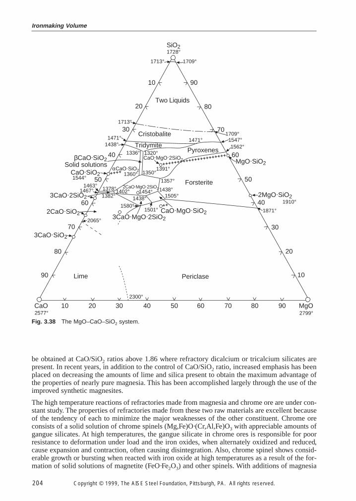
Ironmaking Volume
204 Copyright © 1999, The AISE Steel Foundation, Pittsburgh, PA. All rights reserved.
SiO21728°
1709°1713°
9010
20 80
30 70
6040
5050
60 40
70 30
20
10
80
90
CaO 10 20 30 40 50 60 70 80 90 MgO2799°2577°
2300°
PericlaseLime
Forsterite
Pyroxenes
Cristobalite
Two Liquids
Tridymite
Solid solutions
CaO.MgO.SiO2
CaO.MgO.2SiO2
αCaO.SiO2
3CaO.SiO2
2CaO.SiO2
3CaO.2SiO2
CaO.SiO2
βCaO.SiO2 MgO.SiO2
2MgO.SiO2
2CaO.MgO.2SiO2
++++++++++++++++++++++
++++
1713°
1709°1547°1562°
1391°1350°
1320°1336°
1360°
1378°1382°
1580°
2065° 3CaO.MgO.2SiO2
1438° 1505°1438°
1357°
1402° 1454°
1501°++
1438°1471°
1871°
1910°
1471°
1544°1463°
1467°
Fig. 3.38 The MgO–CaO–SiO2 system.
be obtained at CaO/SiO2 ratios above 1.86 where refractory dicalcium or tricalcium silicates arepresent. In recent years, in addition to the control of CaO/SiO2 ratio, increased emphasis has beenplaced on decreasing the amounts of lime and silica present to obtain the maximum advantage ofthe properties of nearly pure magnesia. This has been accomplished largely through the use of theimproved synthetic magnesites.
The high temperature reactions of refractories made from magnesia and chrome ore are under con-stant study. The properties of refractories made from these two raw materials are excellent becauseof the tendency of each to minimize the major weaknesses of the other constituent. Chrome oreconsists of a solid solution of chrome spinels (Mg,Fe)O·(Cr,Al,Fe)O3 with appreciable amounts ofgangue silicates. At high temperatures, the gangue silicate in chrome ores is responsible for poorresistance to deformation under load and the iron oxides, when alternately oxidized and reduced,cause expansion and contraction, often causing disintegration. Also, chrome spinel shows consid-erable growth or bursting when reacted with iron oxide at high temperatures as a result of the for-mation of solid solutions of magnetite (FeO·Fe2O3) and other spinels. With additions of magnesia
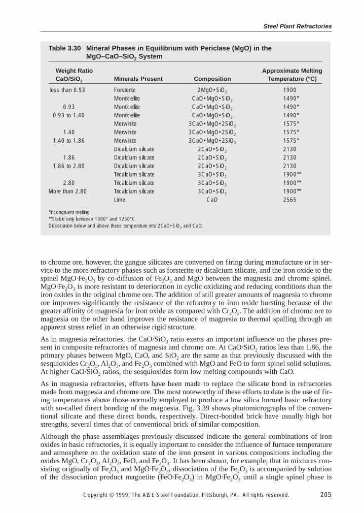
Steel Plant Refractories
Copyright © 1999, The AISE Steel Foundation, Pittsburgh, PA. All rights reserved. 205
to chrome ore, however, the gangue silicates are converted on firing during manufacture or in ser-vice to the more refractory phases such as forsterite or dicalcium silicate, and the iron oxide to thespinel MgO·Fe2O3 by co-diffusion of Fe2O3 and MgO between the magnesia and chrome spinel.MgO·Fe2O3 is more resistant to deterioration in cyclic oxidizing and reducing conditions than theiron oxides in the original chrome ore. The addition of still greater amounts of magnesia to chromeore improves significantly the resistance of the refractory to iron oxide bursting because of thegreater affinity of magnesia for iron oxide as compared with Cr2O3. The addition of chrome ore tomagnesia on the other hand improves the resistance of magnesia to thermal spalling through anapparent stress relief in an otherwise rigid structure.
As in magnesia refractories, the CaO/SiO2 ratio exerts an important influence on the phases pre-sent in composite refractories of magnesia and chrome ore. At CaO/SiO2 ratios less than 1.86, theprimary phases between MgO, CaO, and SiO2 are the same as that previously discussed with thesesquioxides Cr2O3, Al2O3, and Fe2O3 combined with MgO and FeO to form spinel solid solutions.At higher CaO/SiO2 ratios, the sesquioxides form low melting compounds with CaO.
As in magnesia refractories, efforts have been made to replace the silicate bond in refractoriesmade from magnesia and chrome ore. The most noteworthy of these efforts to date is the use of fir-ing temperatures above those normally employed to produce a low silica burned basic refractorywith so-called direct bonding of the magnesia. Fig. 3.39 shows photomicrographs of the conven-tional silicate and these direct bonds, respectively. Direct-bonded brick have usually high hotstrengths, several times that of conventional brick of similar composition.
Although the phase assemblages previously discussed indicate the general combinations of ironoxides in basic refractories, it is equally important to consider the influence of furnace temperatureand atmosphere on the oxidation state of the iron present in various compositions including theoxides MgO, Cr2O3, Al2O3, FeO, and Fe2O3. It has been shown, for example, that in mixtures con-sisting originally of Fe2O3 and MgO·Fe2O3, dissociation of the Fe2O3 is accompanied by solutionof the dissociation product magnetite (FeO·Fe2O3) in MgO·Fe2O3 until a single spinel phase is
Table 3.30 Mineral Phases in Equilibrium with Periclase (MgO) in theMgO–CaO–SiO2 System
Weight Ratio Approximate MeltingCaO/SiO2 Minerals Present Composition Temperature (°C)
less than 0.93 Forsterite 2MgO•SiO2 1900Monticellite CaO•MgO•SiO2 1490*
0.93 Monticellite CaO•MgO•SiO2 1490*0.93 to 1.40 Monticellite CaO•MgO•SiO2 1490*
Merwinite 3CaO•MgO•2SiO2 1575*1.40 Merwinite 3CaO•MgO•2SiO2 1575*
1.40 to 1.86 Merwinite 3CaO•MgO•2SiO2 1575*Dicalcium silicate 2CaO•SiO2 2130
1.86 Dicalcium silicate 2CaO•SiO2 21301.86 to 2.80 Dicalcium silicate 2CaO•SiO2 2130
Tricalcium silicate 3CaO•SiO2 1900**2.80 Tricalcium silicate 3CaO•SiO2 1900**
More than 2.80 Tricalcium silicate 3CaO•SiO2 1900**Lime CaO 2565
*Incongruent melting**Stable only between 1900° and 1250°C.Dissociation below and above these temperature into 2CaO•SiO2 and CaO.
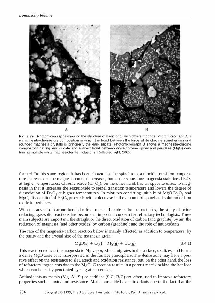
Ironmaking Volume
206 Copyright © 1999, The AISE Steel Foundation, Pittsburgh, PA. All rights reserved.
formed. In this same region, it has been shown that the spinel to sesquioxide transition tempera-ture decreases as the magnesia content increases, but at the same time magnesia stabilizes Fe2O3at higher temperatures. Chrome oxide (Cr2O3), on the other hand, has an opposite effect to mag-nesia in that it increases the sesquioxide to spinel transition temperature and lowers the degree ofdissociation of Fe2O3 at higher temperatures. In mixtures consisting initially of MgO·Fe2O3 andMgO, dissociation of Fe2O3 proceeds with a decrease in the amount of spinel and solution of ironoxide in periclase.
With the advent of carbon bonded refractories and oxide carbon refractories, the study of oxidereducing, gas-solid reactions has become an important concern for refractory technologists. Threemain subjects are important: the straight or the direct oxidation of carbon (and graphite) by air; thereduction of magnesia (and other oxides) by carbon (graphite); and the role of antioxidants.
The rate of the magnesia-carbon reaction below is mainly affected, in addition to temperature, bythe purity and the crystal size of the magnesia grain.
MgO(s) 1 C(s) →Mg(g) 1 CO(g) (3.4.1)
This reaction reduces the magnesia to Mg vapor, which migrates to the surface, oxidizes, and formsa dense MgO zone or is incorporated in the furnace atmosphere. The dense zone may have a pos-itive effect on the resistance to slag attack and oxidation resistance, but, on the other hand, the lossof refractory ingredients due to the MgO–C reaction results in a porous matrix behind the hot facewhich can be easily penetrated by slag at a later stage.
Antioxidants as metals (Mg, Al, Si) or carbides (SiC, B3C) are often used to improve refractoryproperties such as oxidation resistance. Metals are added as antioxidants due to the fact that the
Fig. 3.39 Photomicrographs showing the structure of basic brick with different bonds. Photomicrograph A isa magnesite-chrome ore composition in which the bond between the large white chrome spinel grains androunded magnesia crystals is principally the dark silicate. Photomicrograph B shows a magnesite-chromecomposition having less silicate and a direct bond between white chrome spinel and periclase (MgO) con-taining multiple white magnesioferrite inclusions. Reflected light, 200X.
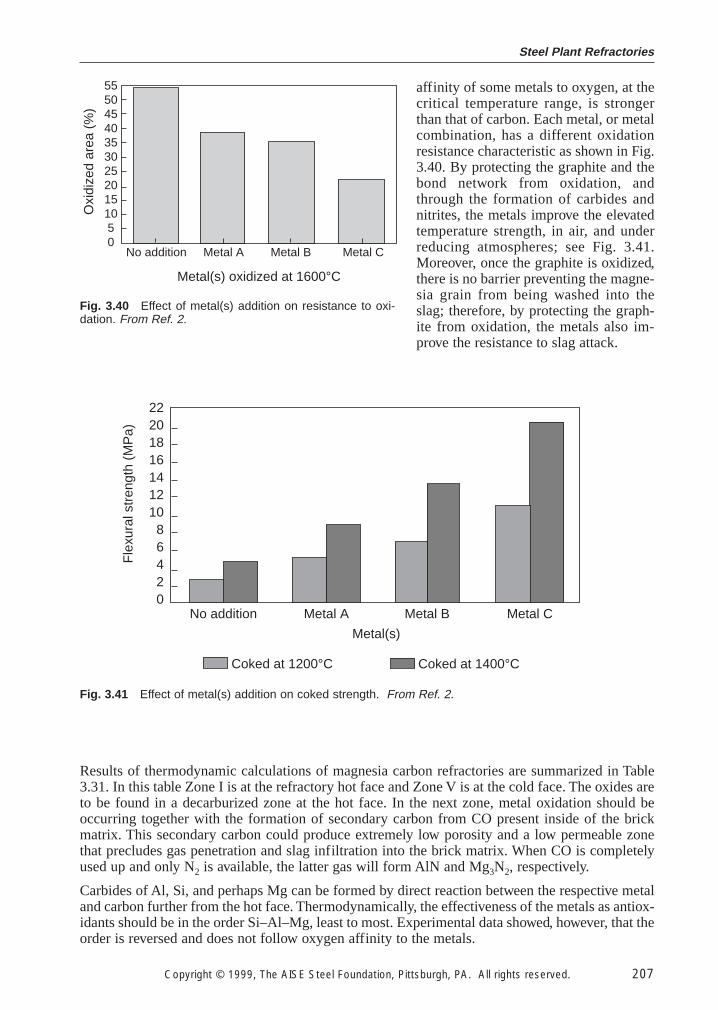
Steel Plant Refractories
Copyright © 1999, The AISE Steel Foundation, Pittsburgh, PA. All rights reserved. 207
affinity of some metals to oxygen, at thecritical temperature range, is strongerthan that of carbon. Each metal, or metalcombination, has a different oxidationresistance characteristic as shown in Fig.3.40. By protecting the graphite and thebond network from oxidation, andthrough the formation of carbides andnitrites, the metals improve the elevatedtemperature strength, in air, and underreducing atmospheres; see Fig. 3.41.Moreover, once the graphite is oxidized,there is no barrier preventing the magne-sia grain from being washed into theslag; therefore, by protecting the graph-ite from oxidation, the metals also im-prove the resistance to slag attack.
Metal(s) oxidized at 1600°C
Oxi
dize
d ar
ea (
%)
5550454035302520151050
No addition Metal A Metal B Metal C
Fig. 3.40 Effect of metal(s) addition on resistance to oxi-dation. From Ref. 2.
No addition Metal A Metal B Metal C
Metal(s)
2220181614121086420
Fle
xura
l str
engt
h (M
Pa)
Coked at 1200°C Coked at 1400°C
Fig. 3.41 Effect of metal(s) addition on coked strength. From Ref. 2.
Results of thermodynamic calculations of magnesia carbon refractories are summarized in Table3.31. In this table Zone I is at the refractory hot face and Zone V is at the cold face. The oxides areto be found in a decarburized zone at the hot face. In the next zone, metal oxidation should beoccurring together with the formation of secondary carbon from CO present inside of the brickmatrix. This secondary carbon could produce extremely low porosity and a low permeable zonethat precludes gas penetration and slag infiltration into the brick matrix. When CO is completelyused up and only N2 is available, the latter gas will form AlN and Mg3N2, respectively.
Carbides of Al, Si, and perhaps Mg can be formed by direct reaction between the respective metaland carbon further from the hot face. Thermodynamically, the effectiveness of the metals as antiox-idants should be in the order Si–Al–Mg, least to most. Experimental data showed, however, that theorder is reversed and does not follow oxygen affinity to the metals.
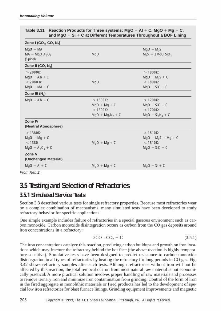
Ironmaking Volume
208 Copyright © 1999, The AISE Steel Foundation, Pittsburgh, PA. All rights reserved.
3.5 Testing and Selection of Refractories
3.5.1 Simulated Service Tests
Section 3.3 described various tests for single refractory properties. Because most refractories wearby a complex combination of mechanisms, many simulated tests have been developed to studyrefractory behavior for specific applications.
One simple example includes failure of refractories in a special gaseous environment such as car-bon monoxide. Carbon monoxide disintegration occurs as carbon from the CO gas deposits aroundiron concentrations in a refractory:
2CO→CO2 1 C (3.5.1)
The iron concentrations catalyze this reaction, producing carbon buildups and growth on iron loca-tions which may fracture the refractory behind the hot face (the above reaction is highly tempera-ture sensitive). Simulative tests have been designed to predict resistance to carbon monoxidedisintegration in all types of refractories by heating the refractory for long periods in CO gas. Fig.3.42 shows refractory samples after such tests. Although refractories without iron will not beaffected by this reaction, the total removal of iron from most natural raw material is not economi-cally practical. A more practical solution involves proper handling of raw materials and processesto remove ternary iron and minimize iron contamination from grinding. Control of the form of ironin the fired aggregate in monolithic materials or fired products has led to the development of spe-cial low iron refractories for blast furnace linings. Grinding equipment improvements and magnetic
Table 3.31 Reaction Products for Three systems: MgO 1 Al 1 C, MgO 1 Mg 1 C,and MgO 1 Si 1 C at Different Temperatures Throughout a BOF Lining
Zone I (CO2, CO, N2)
MgO 1 MA MgO 1 M2SMA 5 MgO Al2O3 MgO M2S 5 2MgO SiO2
(Spinel)
Zone II (CO, N2)
. 2080K: . 1800K:MgO 1 AIN + C MgO 1 M2S + C, 2080 K: MgO , 1800K:MgO 1 MA 1 C MgO 1 SiC 1 C
Zone III (N2)
MgO 1 AIN 1 C . 1600K: . 1700K:MgO 1 Mg 1 C MgO 1 SiC 1 C, 1600K: , 1700K:MgO 1 Mg3N2 1 C MgO 1 Si3N4 1 C
Zone IV(Neutral Atmosphere)
. 1380K: . 1810K:MgO 1 Mg 1 C MgO 1 M2S 1 Mg 1 C, 1380 MgO 1 Mg 1 C , 1810K:MgO 1 Al4C3 1 C MgO 1 SiC 1 C
Zone V(Unchanged Material)
MgO 1 Al 1 C MgO 1 Mg 1 C MgO 1 Si 1 C
From Ref. 2.
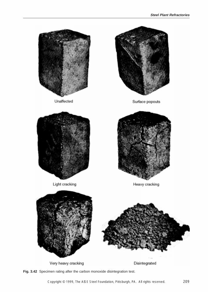
Steel Plant Refractories
Copyright © 1999, The AISE Steel Foundation, Pittsburgh, PA. All rights reserved. 209
Fig. 3.42 Specimen rating after the carbon monoxide disintegration test.
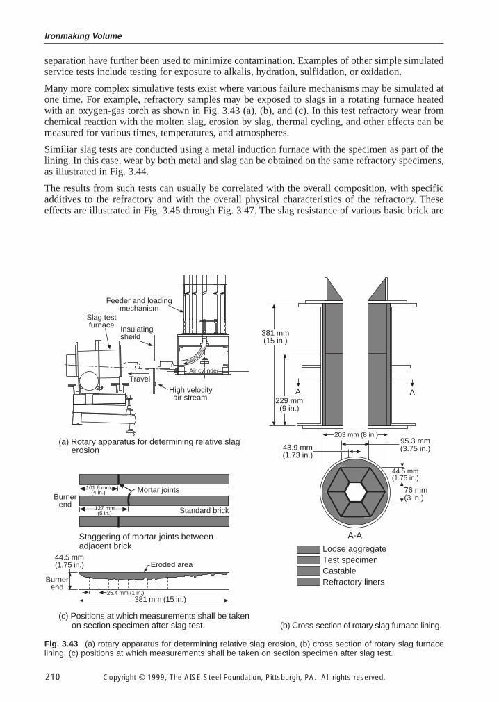
Ironmaking Volume
210 Copyright © 1999, The AISE Steel Foundation, Pittsburgh, PA. All rights reserved.
separation have further been used to minimize contamination. Examples of other simple simulatedservice tests include testing for exposure to alkalis, hydration, sulfidation, or oxidation.
Many more complex simulative tests exist where various failure mechanisms may be simulated atone time. For example, refractory samples may be exposed to slags in a rotating furnace heatedwith an oxygen-gas torch as shown in Fig. 3.43 (a), (b), and (c). In this test refractory wear fromchemical reaction with the molten slag, erosion by slag, thermal cycling, and other effects can bemeasured for various times, temperatures, and atmospheres.
Similiar slag tests are conducted using a metal induction furnace with the specimen as part of thelining. In this case, wear by both metal and slag can be obtained on the same refractory specimens,as illustrated in Fig. 3.44.
The results from such tests can usually be correlated with the overall composition, with specificadditives to the refractory and with the overall physical characteristics of the refractory. Theseeffects are illustrated in Fig. 3.45 through Fig. 3.47. The slag resistance of various basic brick are
381 mm (15 in.)25.4 mm (1 in.)
Eroded area
(c) Positions at which measurements shall be takenon section specimen after slag test.
Burnerend
44.5 mm(1.75 in.)
Staggering of mortar joints betweenadjacent brick
Mortar joints101.6 mm(4 in.)
127 mm(5 in.) Standard brick
Burnerend
(b) Cross-section of rotary slag furnace lining.
229 mm(9 in.)
A A
43.9 mm(1.73 in.)
203 mm (8 in.)95.3 mm(3.75 in.)
44.5 mm(1.75 in.)
76 mm(3 in.)
Loose aggregateTest specimenCastableRefractory liners
A-A
381 mm(15 in.)
(a) Rotary apparatus for determining relative slagerosion
Feeder and loadingmechanism
TravelHigh velocity air stream
Insulatingsheild
Slag testfurnace
Travel ofPel
let
Air cylinder
Fig. 3.43 (a) rotary apparatus for determining relative slag erosion, (b) cross section of rotary slag furnacelining, (c) positions at which measurements shall be taken on section specimen after slag test.
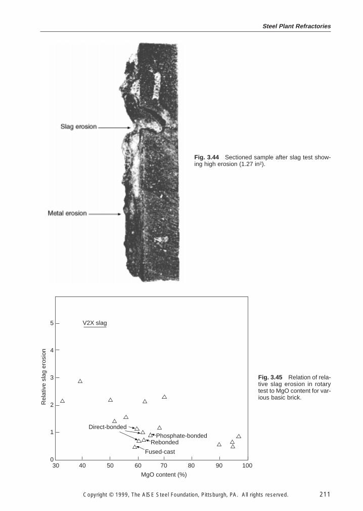
Steel Plant Refractories
Copyright © 1999, The AISE Steel Foundation, Pittsburgh, PA. All rights reserved. 211
Fig. 3.44 Sectioned sample after slag test show-ing high erosion (1.27 in2).
30 40 50 60 70 80 90 100
Rel
ativ
e sl
ag e
rosi
on
5
4
3
2
1
0
MgO content (%)
V2X slag
Direct-bondedPhosphate-bonded
Rebonded
Fused-cast
Fig. 3.45 Relation of rela-tive slag erosion in rotarytest to MgO content for var-ious basic brick.
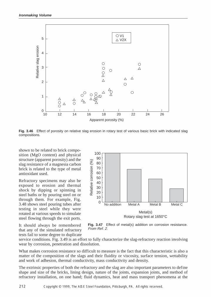
Ironmaking Volume
212 Copyright © 1999, The AISE Steel Foundation, Pittsburgh, PA. All rights reserved.
shown to be related to brick compo-sition (MgO content) and physicalstructure (apparent porosity) and theslag resistance of a magnesia carbonbrick is related to the type of metalantioxidant used.
Refractory specimens may also beexposed to erosion and thermalshock by dipping or spinning insteel baths or by pouring steel on orthrough them. For example, Fig.3.48 shows steel pouring tubes aftertesting in steel while they wererotated at various speeds to simulatesteel flowing through the exit ports.
It should always be rememberedthat any of the simulated refractorytests fail to some degree to duplicateservice conditions. Fig. 3.49 is an effort to fully characterize the slag-refractory reaction involvingwear by corrosion, penetration and dissolution.
What makes corrosion resistance so difficult to measure is the fact that this characteristic is also amatter of the composition of the slags and their fluidity or viscosity, surface tension, wettabilityand work of adhesion, thermal conductivity, mass conductivity and density.
The extrinsic properties of both the refractory and the slag are also important parameters to defineshape and size of the bricks, lining design, nature of the joints, expansion joints, and method ofrefractory installation, on one hand; fluid dynamics, heat and mass transport phenomena at the
10 12 14 16 18 20 22 24 26
Apparent porosity (%)
Rel
ativ
e sl
ag e
rosi
on5
4
3
2
1
0
V1V2X
Fig. 3.46 Effect of porosity on relative slag erosion in rotary test of various basic brick with indicated slagcompositions.
No addition Metal A Metal B Metal C
Metal(s)Rotary slag test at 1650°C
1009080706050403020100
Rel
ativ
e co
rros
ion
(%)
Fig. 3.47 Effect of metal(s) addition on corrosion resistance.From Ref. 2.
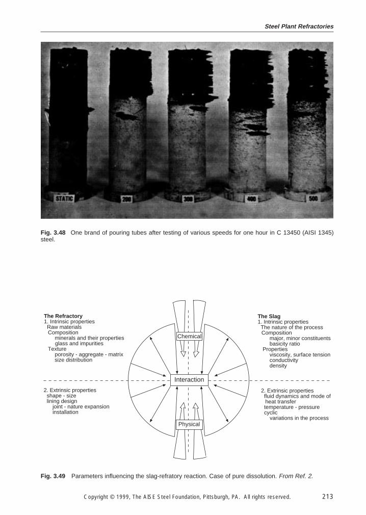
Steel Plant Refractories
Copyright © 1999, The AISE Steel Foundation, Pittsburgh, PA. All rights reserved. 213
Fig. 3.48 One brand of pouring tubes after testing of various speeds for one hour in C 13450 (AISI 1345)steel.
2. Extrinsic properties fluid dynamics and mode ofheat transfer
temperature - pressure cyclic
variations in the process
The Slag1. Intrinsic properties The nature of the processComposition
major, minor constituents basicity ratio
Properties viscosity, surface tension conductivity density
The Refractory1. Intrinsic properties Raw materialsComposition
minerals and their propertiesglass and impurities
Texture porosity - aggregate - matrixsize distribution
2. Extrinsic properties shape - size lining design
joint - nature expansioninstallation
Interaction
Chemical
Physical
Fig. 3.49 Parameters influencing the slag-refratory reaction. Case of pure dissolution. From Ref. 2.
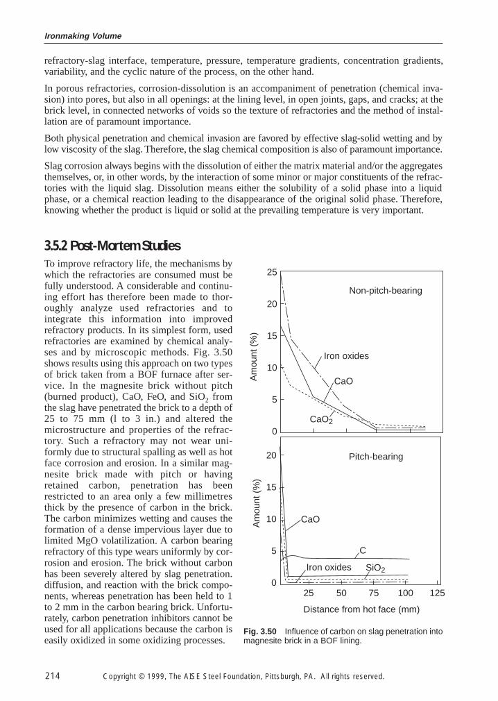
Ironmaking Volume
214 Copyright © 1999, The AISE Steel Foundation, Pittsburgh, PA. All rights reserved.
refractory-slag interface, temperature, pressure, temperature gradients, concentration gradients,variability, and the cyclic nature of the process, on the other hand.
In porous refractories, corrosion-dissolution is an accompaniment of penetration (chemical inva-sion) into pores, but also in all openings: at the lining level, in open joints, gaps, and cracks; at thebrick level, in connected networks of voids so the texture of refractories and the method of instal-lation are of paramount importance.
Both physical penetration and chemical invasion are favored by effective slag-solid wetting and bylow viscosity of the slag. Therefore, the slag chemical composition is also of paramount importance.
Slag corrosion always begins with the dissolution of either the matrix material and/or the aggregatesthemselves, or, in other words, by the interaction of some minor or major constituents of the refrac-tories with the liquid slag. Dissolution means either the solubility of a solid phase into a liquidphase, or a chemical reaction leading to the disappearance of the original solid phase. Therefore,knowing whether the product is liquid or solid at the prevailing temperature is very important.
3.5.2 Post-Mortem Studies
To improve refractory life, the mechanisms bywhich the refractories are consumed must befully understood. A considerable and continu-ing effort has therefore been made to thor-oughly analyze used refractories and tointegrate this information into improvedrefractory products. In its simplest form, usedrefractories are examined by chemical analy-ses and by microscopic methods. Fig. 3.50shows results using this approach on two typesof brick taken from a BOF furnace after ser-vice. In the magnesite brick without pitch(burned product), CaO, FeO, and SiO2 fromthe slag have penetrated the brick to a depth of25 to 75 mm (l to 3 in.) and altered themicrostructure and properties of the refrac-tory. Such a refractory may not wear uni-formly due to structural spalling as well as hotface corrosion and erosion. In a similar mag-nesite brick made with pitch or havingretained carbon, penetration has beenrestricted to an area only a few millimetresthick by the presence of carbon in the brick.The carbon minimizes wetting and causes theformation of a dense impervious layer due tolimited MgO volatilization. A carbon bearingrefractory of this type wears uniformly by cor-rosion and erosion. The brick without carbonhas been severely altered by slag penetration.diffusion, and reaction with the brick compo-nents, whereas penetration has been held to 1to 2 mm in the carbon bearing brick. Unfortu-rately, carbon penetration inhibitors cannot beused for all applications because the carbon iseasily oxidized in some oxidizing processes.
Am
ount
(%
)A
mou
nt (
%)
Non-pitch-bearing
Pitch-bearing
25
20
15
10
5
0
20
15
10
5
025 50 75 100 125
Distance from hot face (mm)
Iron oxides
CaO
CaO2
CaO
C
Iron oxides SiO2
Fig. 3.50 Influence of carbon on slag penetration intomagnesite brick in a BOF lining.
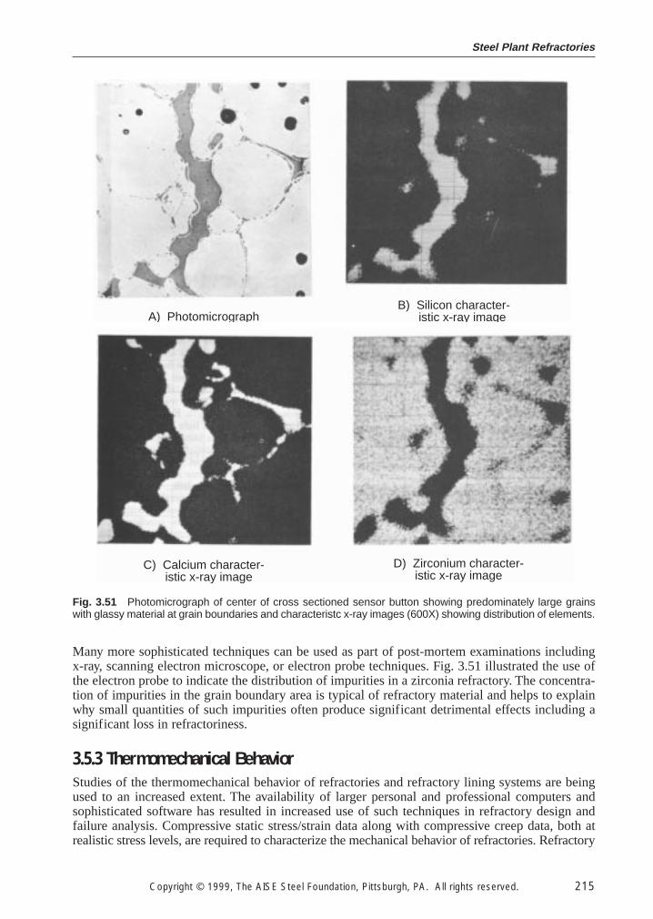
Steel Plant Refractories
Copyright © 1999, The AISE Steel Foundation, Pittsburgh, PA. All rights reserved. 215
Many more sophisticated techniques can be used as part of post-mortem examinations includingx-ray, scanning electron microscope, or electron probe techniques. Fig. 3.51 illustrated the use ofthe electron probe to indicate the distribution of impurities in a zirconia refractory. The concentra-tion of impurities in the grain boundary area is typical of refractory material and helps to explainwhy small quantities of such impurities often produce significant detrimental effects including asignificant loss in refractoriness.
3.5.3 Thermomechanical Behavior
Studies of the thermomechanical behavior of refractories and refractory lining systems are beingused to an increased extent. The availability of larger personal and professional computers andsophisticated software has resulted in increased use of such techniques in refractory design andfailure analysis. Compressive static stress/strain data along with compressive creep data, both atrealistic stress levels, are required to characterize the mechanical behavior of refractories. Refractory
A) PhotomicrographB) Silicon character- istic x-ray image
C) Calcium character- istic x-ray image
D) Zirconium character-istic x-ray image
Fig. 3.51 Photomicrograph of center of cross sectioned sensor button showing predominately large grainswith glassy material at grain boundaries and characteristc x-ray images (600X) showing distribution of elements.
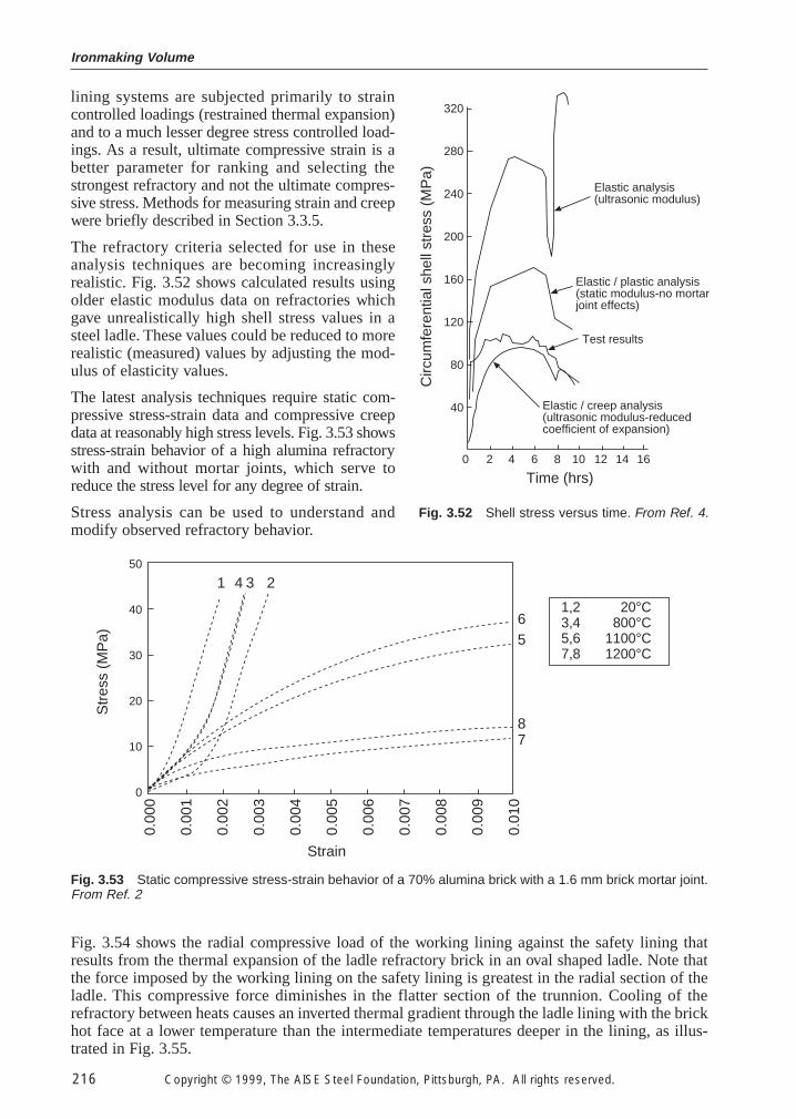
Ironmaking Volume
216 Copyright © 1999, The AISE Steel Foundation, Pittsburgh, PA. All rights reserved.
lining systems are subjected primarily to straincontrolled loadings (restrained thermal expansion)and to a much lesser degree stress controlled load-ings. As a result, ultimate compressive strain is abetter parameter for ranking and selecting thestrongest refractory and not the ultimate compres-sive stress. Methods for measuring strain and creepwere briefly described in Section 3.3.5.
The refractory criteria selected for use in theseanalysis techniques are becoming increasinglyrealistic. Fig. 3.52 shows calculated results usingolder elastic modulus data on refractories whichgave unrealistically high shell stress values in asteel ladle. These values could be reduced to morerealistic (measured) values by adjusting the mod-ulus of elasticity values.
The latest analysis techniques require static com-pressive stress-strain data and compressive creepdata at reasonably high stress levels. Fig. 3.53 showsstress-strain behavior of a high alumina refractorywith and without mortar joints, which serve toreduce the stress level for any degree of strain.
Stress analysis can be used to understand andmodify observed refractory behavior.
Elastic analysis(ultrasonic modulus)
Elastic / plastic analysis(static modulus-no mortarjoint effects)
Test results
Elastic / creep analysis(ultrasonic modulus-reducedcoefficient of expansion)
Time (hrs)
Circ
umfe
rent
ial s
hell
stre
ss (
MP
a)
320
280
240
200
160
120
80
40
0 2 4 6 8 10 12 14 16
Fig. 3.52 Shell stress versus time. From Ref. 4.
50
40
30
20
10
0
Str
ess
(MP
a)
Strain
0.00
0
0.00
1
0.00
2
0.00
3
0.00
4
0.00
5
0.00
6
0.00
7
0.00
8
0.00
9
0.01
0
65
87
1 4 3 2
1,2 20°C3,4 800°C5,6 1100°C7,8 1200°C
Fig. 3.53 Static compressive stress-strain behavior of a 70% alumina brick with a 1.6 mm brick mortar joint.From Ref. 2
Fig. 3.54 shows the radial compressive load of the working lining against the safety lining thatresults from the thermal expansion of the ladle refractory brick in an oval shaped ladle. Note thatthe force imposed by the working lining on the safety lining is greatest in the radial section of theladle. This compressive force diminishes in the flatter section of the trunnion. Cooling of therefractory between heats causes an inverted thermal gradient through the ladle lining with the brickhot face at a lower temperature than the intermediate temperatures deeper in the lining, as illus-trated in Fig. 3.55.
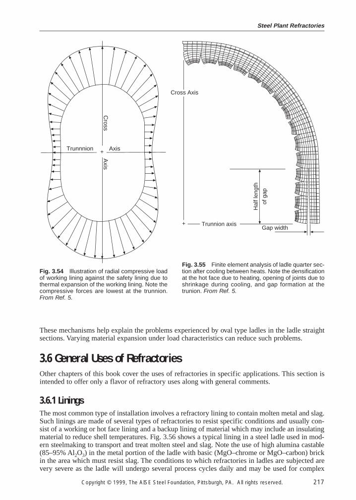
Steel Plant Refractories
Copyright © 1999, The AISE Steel Foundation, Pittsburgh, PA. All rights reserved. 217
These mechanisms help explain the problems experienced by oval type ladles in the ladle straightsections. Varying material expansion under load characteristics can reduce such problems.
3.6 General Uses of Refractories
Other chapters of this book cover the uses of refractories in specific applications. This section isintended to offer only a flavor of refractory uses along with general comments.
3.6.1 Linings
The most common type of installation involves a refractory lining to contain molten metal and slag.Such linings are made of several types of refractories to resist specific conditions and usually con-sist of a working or hot face lining and a backup lining of material which may include an insulatingmaterial to reduce shell temperatures. Fig. 3.56 shows a typical lining in a steel ladle used in mod-ern steelmaking to transport and treat molten steel and slag. Note the use of high alumina castable(85–95% Al2O3) in the metal portion of the ladle with basic (MgO–chrome or MgO–carbon) brickin the area which must resist slag. The conditions to which refractories in ladles are subjected arevery severe as the ladle will undergo several process cycles daily and may be used for complex
Trunnnion Axis
Cross
Axis
+
Fig. 3.54 Illustration of radial compressive loadof working lining against the safety lining due tothermal expansion of the working lining. Note thecompressive forces are lowest at the trunnion.From Ref. 5.
+
Cross Axis
Hal
f len
gth
of g
ap
Gap widthTrunnion axis
Fig. 3.55 Finite element analysis of ladle quarter sec-tion after cooling between heats. Note the densificationat the hot face due to heating, opening of joints due toshrinkage during cooling, and gap formation at thetrunion. From Ref. 5.
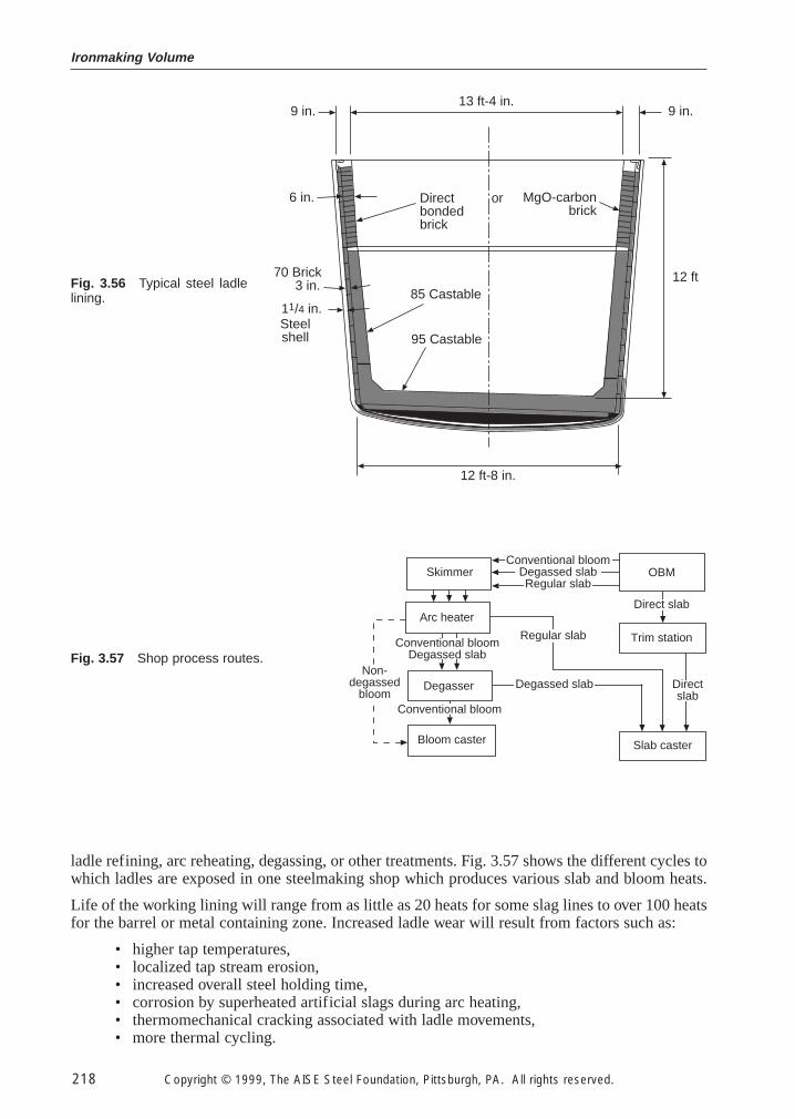
Ironmaking Volume
218 Copyright © 1999, The AISE Steel Foundation, Pittsburgh, PA. All rights reserved.
ladle refining, arc reheating, degassing, or other treatments. Fig. 3.57 shows the different cycles towhich ladles are exposed in one steelmaking shop which produces various slab and bloom heats.
Life of the working lining will range from as little as 20 heats for some slag lines to over 100 heatsfor the barrel or metal containing zone. Increased ladle wear will result from factors such as:
• higher tap temperatures,• localized tap stream erosion,• increased overall steel holding time,• corrosion by superheated artificial slags during arc heating,• thermomechanical cracking associated with ladle movements,• more thermal cycling.
Directbondedbrick
MgO-carbonbrick
or
85 Castable
95 Castable
6 in.
9 in.
3 in.
11/4 in.
12 ft
12 ft-8 in.
70 Brick
Steelshell
9 in.13 ft-4 in.
Fig. 3.56 Typical steel ladlelining.
Skimmer
Arc heater
Degasser
Bloom caster
Trim station
OBM
Slab caster
Conventional bloomDegassed slabRegular slab
Direct slab
Directslab
Degassed slabNon-
degassedbloom
Regular slabConventional bloom
Degassed slab
Conventional bloom
Fig. 3.57 Shop process routes.
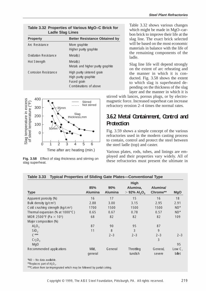
Steel Plant Refractories
Copyright © 1999, The AISE Steel Foundation, Pittsburgh, PA. All rights reserved. 219
Table 3.32 shows various changeswhich might be made in MgO–car-bon brick to improve their life at theslag line. The exact brick selectedwill be based on the most economicmaterials in balance with the life ofthe remaining components of theladle.
Slag line life will depend stronglyon the extent of arc reheating andthe manner in which it is con-ducted. Fig. 3.58 shows the extentto which slag is superheated de-pending on the thickness of the slaglayer and the manner in which it is
stirred with lances, porous plugs, or by electro-magnetic force. Increased superheat can increaserefractory erosion 2–4 times the normal rates.
3.6.2 Metal Containment, Control and
Protection
Fig. 3.59 shows a simple concept of the variousrefractories used in the modern casting processto contain, control and protect the steel betweenthe steel ladle (top) and caster.
Various plates, rods, tubes, and linings are em-ployed and their properties vary widely. All ofthese refractories must present the ultimate in
Table 3.32 Properties of Various MgO–C Brick forLadle Slag Lines
Property Better Resistance Obtained by
Arc Resistance More graphiteHigher purity graphite
Oxidation Resistance Metal(s)
Hot Strength Metal(s)Metals and higher purity graphite
Corrosion Resistance High purity sintered grainHigh purity graphiteFused grainCombinations of above
Time after arc heating (min.)
400
300
200
100
0
0 1 2 3 4 5 6
50mm
Slagthickness,mm
StirredNot stirred
35mm
Sla
g te
mpe
ratu
re in
exc
ess
of s
teel
tem
pera
ture
(°F
)
Fig. 3.58 Effect of slag thickness and stirring onslag superheat.
Table 3.33 Typical Properties of Sliding Gate Plates—Conventional Type
High85% 90% Alumina, Alumina/
Type Alumina Alumina . 92% Al2O3 Chrome** MgO
Apparent porosity (%) 16 17 15 16 18Bulk density (g/cm3) 2.88 3.00 3.15 2.95 2.91Cold crushing strength (kg/cm2) 1700 1500 1500 1500 ND*Thermal expansion (% at 1000°C) 0.65 0.67 0.78 0.57 ND*MOR 2500°F (Pa 3 105) 68 82 82 82 109Major composition (%)
Al2O3 87 90 95 87SiO2 11 8 3 9C*** 2–3 2–3 2–3 2–3Cr2O3 3MgO 95
Recommended applications Mild, General Throttling General, Low C,general tundish severe billet
*ND – No data availlable.**Replaces part of Al2O3.***Carbon from tar-impregnated which may be followed by partial coking.
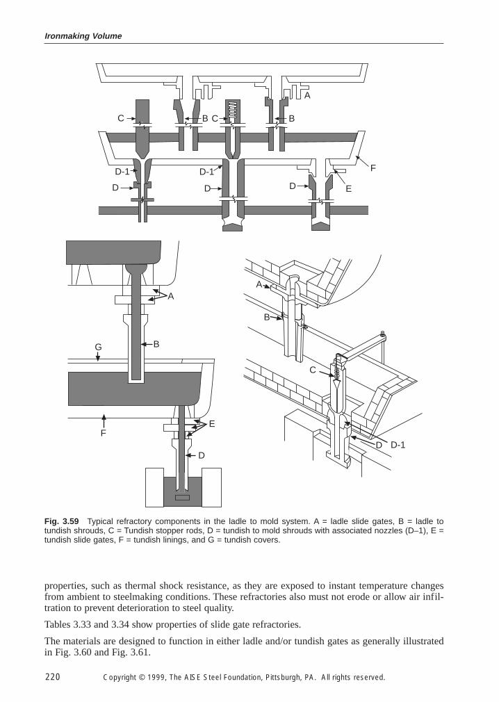
Ironmaking Volume
220 Copyright © 1999, The AISE Steel Foundation, Pittsburgh, PA. All rights reserved.
properties, such as thermal shock resistance, as they are exposed to instant temperature changesfrom ambient to steelmaking conditions. These refractories also must not erode or allow air infil-tration to prevent deterioration to steel quality.
Tables 3.33 and 3.34 show properties of slide gate refractories.
The materials are designed to function in either ladle and/or tundish gates as generally illustratedin Fig. 3.60 and Fig. 3.61.
C B C B
A
D-1
D
D-1
DD E
F
A
BG
FE
D
B
C
D D-1
A
Fig. 3.59 Typical refractory components in the ladle to mold system. A = ladle slide gates, B = ladle totundish shrouds, C = Tundish stopper rods, D = tundish to mold shrouds with associated nozzles (D–1), E =tundish slide gates, F = tundish linings, and G = tundish covers.
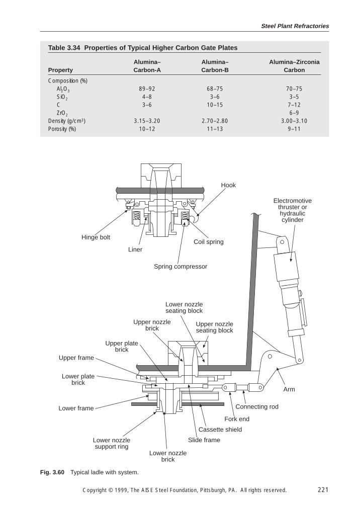
Steel Plant Refractories
Copyright © 1999, The AISE Steel Foundation, Pittsburgh, PA. All rights reserved. 221
Hook
Coil spring
Spring compressor
Liner
Hinge bolt
Electromotivethruster orhydrauliccylinder
Arm
Connecting rod
Fork end
Cassette shield
Slide frame
Lower nozzlebrick
Lower nozzlesupport ring
Lower frame
Lower platebrick
Upper frame
Upper platebrick
Upper nozzlebrick
Lower nozzleseating block
Upper nozzleseating block
Fig. 3.60 Typical ladle with system.
Table 3.34 Properties of Typical Higher Carbon Gate Plates
Alumina– Alumina– Alumina–ZirconiaProperty Carbon-A Carbon-B Carbon
Composition (%)Al2O3 89–92 68–75 70–75SiO2 4–8 3–6 3–5C 3–6 10–15 7–12ZrO2 6–9
Density (g/cm3) 3.15–3.20 2.70–2.80 3.00–3.10Porosity (%) 10–12 11–13 9–11
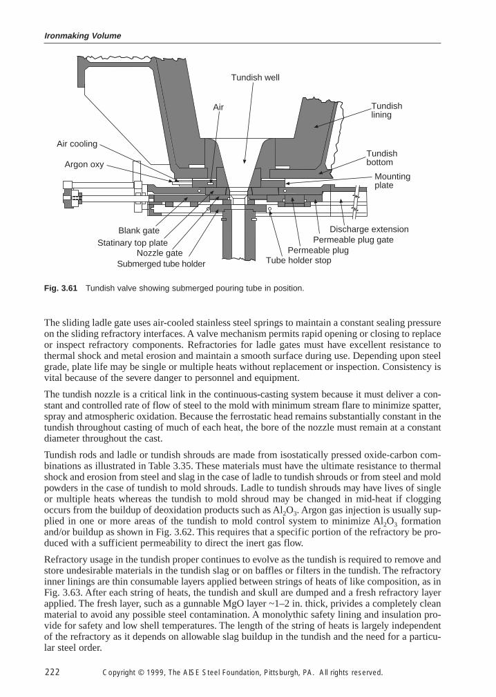
Ironmaking Volume
222 Copyright © 1999, The AISE Steel Foundation, Pittsburgh, PA. All rights reserved.
The sliding ladle gate uses air-cooled stainless steel springs to maintain a constant sealing pressureon the sliding refractory interfaces. A valve mechanism permits rapid opening or closing to replaceor inspect refractory components. Refractories for ladle gates must have excellent resistance tothermal shock and metal erosion and maintain a smooth surface during use. Depending upon steelgrade, plate life may be single or multiple heats without replacement or inspection. Consistency isvital because of the severe danger to personnel and equipment.
The tundish nozzle is a critical link in the continuous-casting system because it must deliver a con-stant and controlled rate of flow of steel to the mold with minimum stream flare to minimize spatter,spray and atmospheric oxidation. Because the ferrostatic head remains substantially constant in thetundish throughout casting of much of each heat, the bore of the nozzle must remain at a constantdiameter throughout the cast.
Tundish rods and ladle or tundish shrouds are made from isostatically pressed oxide-carbon com-binations as illustrated in Table 3.35. These materials must have the ultimate resistance to thermalshock and erosion from steel and slag in the case of ladle to tundish shrouds or from steel and moldpowders in the case of tundish to mold shrouds. Ladle to tundish shrouds may have lives of singleor multiple heats whereas the tundish to mold shroud may be changed in mid-heat if cloggingoccurs from the buildup of deoxidation products such as Al2O3. Argon gas injection is usually sup-plied in one or more areas of the tundish to mold control system to minimize Al2O3 formationand/or buildup as shown in Fig. 3.62. This requires that a specific portion of the refractory be pro-duced with a sufficient permeability to direct the inert gas flow.
Refractory usage in the tundish proper continues to evolve as the tundish is required to remove andstore undesirable materials in the tundish slag or on baffles or filters in the tundish. The refractoryinner linings are thin consumable layers applied between strings of heats of like composition, as inFig. 3.63. After each string of heats, the tundish and skull are dumped and a fresh refractory layerapplied. The fresh layer, such as a gunnable MgO layer ~1–2 in. thick, privides a completely cleanmaterial to avoid any possible steel contamination. A monolythic safety lining and insulation pro-vide for safety and low shell temperatures. The length of the string of heats is largely independentof the refractory as it depends on allowable slag buildup in the tundish and the need for a particu-lar steel order.
Tundish well
Air
Air cooling
Argon oxy
Blank gateStatinary top plate
Nozzle gateSubmerged tube holder Tube holder stop
Permeable plugPermeable plug gate
Discharge extension
Mountingplate
Tundishbottom
Tundishlining
Fig. 3.61 Tundish valve showing submerged pouring tube in position.
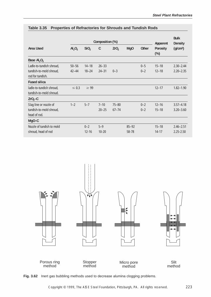
Steel Plant Refractories
Copyright © 1999, The AISE Steel Foundation, Pittsburgh, PA. All rights reserved. 223
Porous ringmethod
Stoppermethod
Micro poremethod
Slitmethod
Fig. 3.62 Inert gas bubbling methods used to decrease alumina clogging problems.
Table 3.35 Properties of Refractories for Shrouds and Tundish Rods
BulkComposition (%) Apparent Density
Area Used Al2O3 SiO2 C ZrO2 MgO Other Porosity (g/cm3)(%)
Base Al2O3
Ladle-to-tundish shroud, 50–56 14–18 26–33 0–5 15–18 2.30–2.44tundish-to-mold shroud, 42–44 18–24 24–31 0–3 0–2 12–18 2.20–2.35rod for tundish.
Fused silica
ladle-to-tundish shroud, # 0.3 $ 99 12–17 1.82–1.90tundish-to-mold shroud.
ZrO2–C
Slag line or nozzle of 1–2 5–7 7–10 75–80 0–2 12–16 3.57–4.18tundish-to-mold shroud, 20–25 67–74 0–2 15–18 3.20–3.60head of rod.
MgO–C
Nozzle of tundish to mold 0–2 5–9 85–92 15–18 2.46–2.51shroud, head of rod 12-16 10-20 58-78 14-17 2.25-2.50
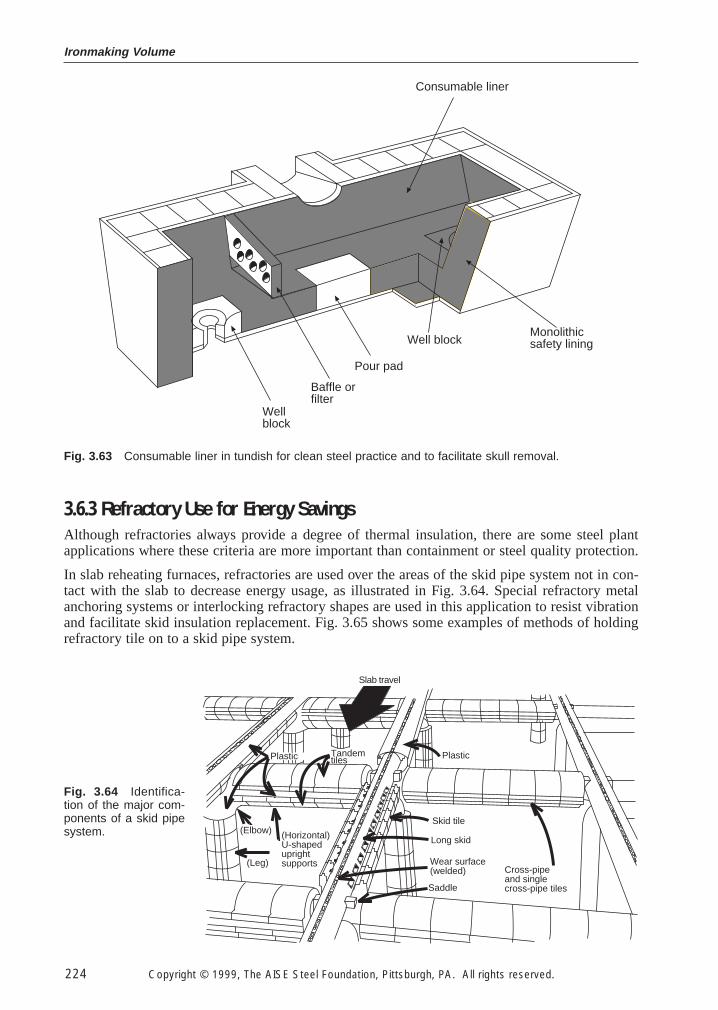
Ironmaking Volume
224 Copyright © 1999, The AISE Steel Foundation, Pittsburgh, PA. All rights reserved.
3.6.3 Refractory Use for Energy Savings
Although refractories always provide a degree of thermal insulation, there are some steel plantapplications where these criteria are more important than containment or steel quality protection.
In slab reheating furnaces, refractories are used over the areas of the skid pipe system not in con-tact with the slab to decrease energy usage, as illustrated in Fig. 3.64. Special refractory metalanchoring systems or interlocking refractory shapes are used in this application to resist vibrationand facilitate skid insulation replacement. Fig. 3.65 shows some examples of methods of holdingrefractory tile on to a skid pipe system.
Consumable liner
Wellblock
Baffle orfilter
Pour pad
Well blockMonolithicsafety lining
Fig. 3.63 Consumable liner in tundish for clean steel practice and to facilitate skull removal.
Slab travel
Plastic Tandemtiles
(Horizontal)U-shapeduprightsupports
(Elbow)
(Leg)
Plastic
Skid tile
Long skid
Wear surface(welded)
Saddle
Cross-pipeand singlecross-pipe tiles
Fig. 3.64 Identifica-tion of the major com-ponents of a skid pipesystem.
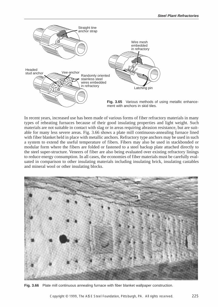
Steel Plant Refractories
Copyright © 1999, The AISE Steel Foundation, Pittsburgh, PA. All rights reserved. 225
In recent years, increased use has been made of various forms of fiber refractory materials in manytypes of reheating furnaces because of their good insulating properties and light weight. Suchmaterials are not suitable in contact with slag or in areas requiring abrasion resistance, but are suit-able for many less severe areas. Fig. 3.66 shows a plate mill continuous-annealing furnace linedwith fiber blanket held in place with metallic anchors. Refractory type anchors may be used in sucha system to extend the useful temperature of fibers. Fibers may also be used in stackbonded ormodular form where the fibers are folded or fastened to a steel backup plate attached directly tothe steel super-structure. Veneers of fiber are also being evaluated over existing refractory liningsto reduce energy consumption. In all cases, the economies of fiber materials must be carefully eval-uated in comparison to other insulating materials including insulating brick, insulating castablesand mineral wool or other insulating blocks.
Straight tineanchor strap
Wire meshembeddedin refractory
Latching pin
Vee-anchorRandomly orientedstainless steelwires embeddedin refractory
Headedstud anchor
Fig. 3.65 Various methods of using metallic enhance-ment with anchors in skid tiles.
Fig. 3.66 Plate mill continuous annealing furnace with fiber blanket wallpaper construction.
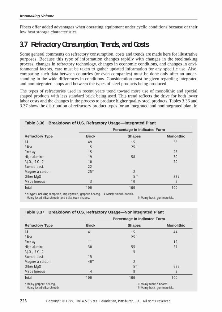
Ironmaking Volume
226 Copyright © 1999, The AISE Steel Foundation, Pittsburgh, PA. All rights reserved.
Fibers offer added advantages when operating equipment under cyclic conditions because of theirlow heat storage characteristics.
3.7 Refractory Consumption, Trends, and Costs
Some general comments on refractory consumption, costs and trends are made here for illustrativepurposes. Because this type of information changes rapidly with changes in the steelmakingprocess, changes in refractory technology, changes in economic conditions, and changes in envi-ronmental factors, care must be taken to gather updated information for any specific use. Also,comparing such data between countries (or even companies) must be done only after an under-standing in the wide differences in conditions. Consideration must be given regarding integratedand nonintegrated shops and between the types of steel products being produced.
The types of refractories used in recent years trend toward more use of monolithic and specialshaped products with less standard brick being used. This trend reflects the drive for both lowerlabor costs and the changes in the process to produce higher quality steel products. Tables 3.36 and3.37 show the distribution of refractory product types for an integrated and nonintegrated plant in
Table 3.36 Breakdown of U.S. Refractory Usage—Integrated Plant
Percentage In Indicated Form
Refractory Type Brick Shapes Monolithic
All 49 15 36Silica 5 25 †
Fireclay 15 25High alumina 19 58 30Al2O3–SiC–C 10 20Burned basic 22Magnesia carbon 25* 2Other MgO 5 ‡ 23§Miscellaneous 3 10 2
Total 100 100 100
* All types including tempered, impregnated, graphite bearing. ‡ Mainly tundish boards.† Mainly fused-silica shrouds and coke oven shapes. § Mainly basic gun materials.
Table 3.37 Breakdown of U.S. Refractory Usage—Nonintegrated Plant
Percentage In Indicated Form
Refractory Type Brick Shapes Monolithic
All 41 15 44Silica 25 †
Fireclay 11 12High alumina 30 55 21Al2O3–SiC–C 5Burned basic 15Magnesia carbon 40* 2Other MgO 5‡ 65§Miscellaneous 4 8 2
Total 100 100 100
* Mainly graphite bearing. ‡ Mainly tundish boards.† Mainly fused-silica shrouds § Mainly basic gun materials.
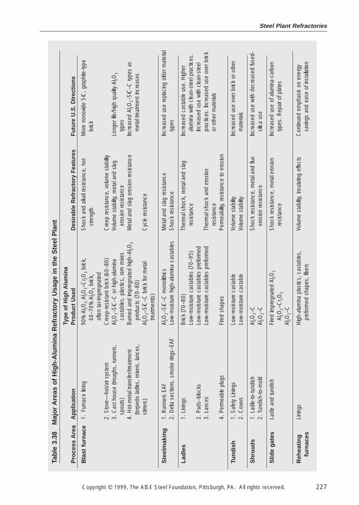
Steel Plant Refractories
Copyright © 1999, The AISE Steel Foundation, Pittsburgh, PA. All rights reserved. 227
Tabl
e 3.
38M
ajor
Are
as o
f Hig
h-A
lum
ina
Ref
ract
ory
Usa
ge in
the
Ste
el P
lant
Pro
cess
Are
a
Bla
st fu
rnac
e
Ste
elm
akin
g
Ladl
es
Tund
ish
Shr
ouds
Slid
e ga
tes
Reh
eatin
gfu
rnac
es
App
licat
ion
1.Fu
rnac
e lin
ing
2. S
tove
—ho
t/air
syst
em3.
Cas
t hou
se (t
roug
hs, r
unne
rs,
spou
ts)
4. H
ot-m
etal
tran
sfer
/trea
tmen
t(to
rped
o la
dles
, mixe
rs, l
ance
s,st
irrer
s)
1. R
unne
rs E
AF2.
Del
ta s
ectio
ns, s
mok
e rin
gs–E
AF
1. L
inin
gs
2. P
ads–
bloc
ks3.
Lan
ces
4. P
erm
eabl
e pl
ugs
1. S
afet
y Li
ning
s2.
Cov
ers
1. L
adle
-to-tu
ndish
2. T
undi
sh-to
-mol
d
Ladl
e an
d tu
ndish
Lini
ngs
Type
of H
igh
Alu
min
aP
rodu
ct U
sed
90%
Al 2O
3, A
l 2O3–
Cr 2O
3br
ick,
60–7
0% A
l 2O3
bric
k,
ofte
n ta
r-im
preg
nate
dC
reep
-resis
tant
bric
k (6
0–80
)Al
2O3–
SiC
–C o
r hig
h-al
umin
aca
stab
les,
pla
stic
s, ra
m m
ixes
Bur
ned
and
impr
egna
ted
high
–Al 2O
3
prod
ucts
(70–
80)
Al2O
3–S
iC–C
bric
k fo
r met
altre
atm
ent(s
)
Al2O
3–S
iC–C
mon
olith
ics
Low
-moi
stur
e hi
gh-a
lum
ina
cast
able
s
Bric
k (7
0–80
)Lo
w-m
oist
ure
cast
able
s (7
0–95
)Lo
w-m
oist
ure
cast
able
s pr
efor
med
Low
-moi
stur
e ca
stab
les
pref
orm
ed
Fire
d sh
apes
Low
-moi
stur
e ca
stab
leLo
w-m
oist
ure
cast
able
Al2O
3–C
Al2O
3–C
Fire
d im
preg
nate
d Al
2O3
Al2O
3–C
r 2O
3
Al2O
3–C
Hig
h-al
umin
a pl
astic
s, c
asta
bles
,pr
efor
med
sha
pes,
fibe
rs
Des
irabl
e R
efra
ctor
y Fe
atur
es
Sho
ck a
nd a
lkali r
esist
ance
, hot
stre
ngth
Cre
ep re
sista
nce,
vol
ume
stab
ility
Volu
me
stab
ility,
met
al a
nd s
lag
eros
ion
resis
tanc
eM
etal
and
sla
g er
osio
n re
sista
nce
Cyc
le re
sista
nce
Met
al a
nd s
lag
resis
tanc
eS
hock
resis
tanc
e
Ther
mal
sho
ck, m
etal
and
sla
gre
sista
nce
Ther
mal
sho
ck a
nd e
rosio
nre
sista
nce
Perm
eabi
lity, r
esist
ance
to e
rosio
n
Volu
me
stab
ility
Volu
me
stab
ility
Sho
ck re
sista
nce,
met
al a
nd fl
uxer
osio
n re
sista
nce
Sho
ck re
sista
nce,
met
al e
rosio
nre
sista
nce
Volu
me
stab
ility,
insu
latin
g ef
fect
s
Futu
re U
.S. D
irect
ions
Mor
e no
noxid
e S
iC, g
raph
ite-ty
pebr
ick
Long
er lif
e/hi
gh q
uality
Al 2O
3
type
sIn
crea
sed
Al2O
3–S
iC–C
type
s as
met
al tr
eatm
ent i
ncre
ases
Incr
ease
d us
e re
plac
ing
olde
r mat
eria
lty
pes
Incr
ease
d ca
stab
le u
se. H
ighe
ral
umin
a w
ith c
lean
-ste
el p
ract
ices
.In
crea
sed
use
with
cle
an-s
teel
prac
tices
. Inc
reas
ed u
se o
ver b
rick
or o
ther
mat
eria
ls
Incr
ease
d us
e ov
er b
rick
or o
ther
mat
eria
ls
Incr
ease
d us
e w
ith d
ecre
ased
fuse
d-sil
ica
use
Incr
ease
d us
e of
alu
min
a-ca
rbon
type
s. R
epai
r of p
late
s
Con
tinue
d em
phas
is on
ene
rgy
savin
gs a
nd e
ase
of in
stal
latio
n
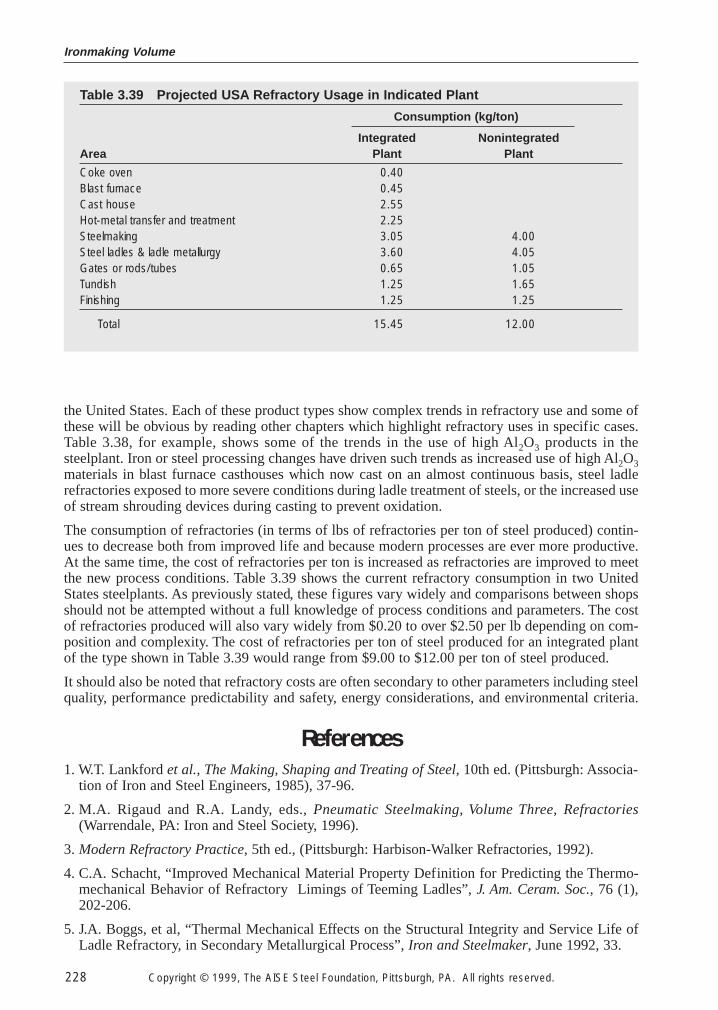
Ironmaking Volume
228 Copyright © 1999, The AISE Steel Foundation, Pittsburgh, PA. All rights reserved.
the United States. Each of these product types show complex trends in refractory use and some ofthese will be obvious by reading other chapters which highlight refractory uses in specific cases.Table 3.38, for example, shows some of the trends in the use of high Al2O3 products in thesteelplant. Iron or steel processing changes have driven such trends as increased use of high Al2O3materials in blast furnace casthouses which now cast on an almost continuous basis, steel ladlerefractories exposed to more severe conditions during ladle treatment of steels, or the increased useof stream shrouding devices during casting to prevent oxidation.
The consumption of refractories (in terms of lbs of refractories per ton of steel produced) contin-ues to decrease both from improved life and because modern processes are ever more productive.At the same time, the cost of refractories per ton is increased as refractories are improved to meetthe new process conditions. Table 3.39 shows the current refractory consumption in two UnitedStates steelplants. As previously stated, these figures vary widely and comparisons between shopsshould not be attempted without a full knowledge of process conditions and parameters. The costof refractories produced will also vary widely from $0.20 to over $2.50 per lb depending on com-position and complexity. The cost of refractories per ton of steel produced for an integrated plantof the type shown in Table 3.39 would range from $9.00 to $12.00 per ton of steel produced.
It should also be noted that refractory costs are often secondary to other parameters including steelquality, performance predictability and safety, energy considerations, and environmental criteria.
References
1. W.T. Lankford et al., The Making, Shaping and Treating of Steel, 10th ed. (Pittsburgh: Associa-tion of Iron and Steel Engineers, 1985), 37-96.
2. M.A. Rigaud and R.A. Landy, eds., Pneumatic Steelmaking, Volume Three, Refractories(Warrendale, PA: Iron and Steel Society, 1996).
3. Modern Refractory Practice, 5th ed., (Pittsburgh: Harbison-Walker Refractories, 1992).
4. C.A. Schacht, “Improved Mechanical Material Property Definition for Predicting the Thermo-mechanical Behavior of Refractory Limings of Teeming Ladles”, J. Am. Ceram. Soc., 76 (1),202-206.
5. J.A. Boggs, et al, “Thermal Mechanical Effects on the Structural Integrity and Service Life ofLadle Refractory, in Secondary Metallurgical Process”, Iron and Steelmaker, June 1992, 33.
Table 3.39 Projected USA Refractory Usage in Indicated Plant
Consumption (kg/ton)
Integrated NonintegratedArea Plant Plant
Coke oven 0.40Blast furnace 0.45Cast house 2.55Hot-metal transfer and treatment 2.25Steelmaking 3.05 4.00Steel ladles & ladle metallurgy 3.60 4.05Gates or rods/tubes 0.65 1.05Tundish 1.25 1.65Finishing 1.25 1.25
Total 15.45 12.00