Embed Size (px)
Citation preview


Propositions
1. Emulsification with high porosity microsieves is an excellent example of how micro-
engineered systems can yield well-defined products at high throughputs (this thesis).
2. Phase separation in microdroplets is an elegant method to obtain microcapsules with
tunable morphology of the shell and internal core structure (this thesis).
3. Microtechnology makes efficient use of energy and raw materials and therefore can
contribute to a sustainable future.
4. Like the effect of gravity on physical phenomena at macroscopic scales, the influence
of additives on structure formation on microscopic scale in polymeric microcapsules
cannot be neglected.
5. A combined conceptual design of products and processes in academic research creates
synergy and rapid innovations in industries.
6. Practicing science without a good vision is like looking into bright light with blind
eyes.
7. For universal solutions of problems related to global warming people from different
cultural backgrounds having different views should work together.
8. Foods are not healthy or unhealthy, it is the diet that a consumer chooses which is
healthy or unhealthy.
Propositions belonging to PhD thesis
“Structuring microspheres”
Wageningen, 23rd September 2011
Nagesh A. Wagdare


Structuring Microspheres
Nagesh A. Wagdare

Thesis committee
Thesis supervisors
Prof. dr. Cees J.M. van Rijn
Professor of Microsystem and NanoTechnology for Agrofood and Health
Wageningen University
Prof. dr. ir. Remko M. Boom
Professor of Food Process Engineering
Wageningen University
Thesis co-supervisor
Dr. Antonius T.M. Marcelis
Assistant professor, Laboratory of Organic Chemistry
Wageningen University
Other members
Prof. dr. Martien A. Cohen Stuart
Wageningen University
Prof. dr. ir. Wim E. Hennink
Utrecht University
Prof. dr. Jan Meuldijk
Eindhoven University of Technology
Dr. ir. Gert J. Veldhuis
Nanomi BV, Oldenzaal
This research was conducted under the auspices of the Graduate School of VLAG

Structuring Microspheres
Nagesh A. Wagdare
Thesis
Submitted in fulfilment of the requirements for the degree of doctor
at Wageningen University
by the authority of the Rector Magnificus
Prof. dr. M.J. Kropff,
in the presence of the
Thesis Committee appointed by the Academic Board
to be defended in public
on Friday 23 September 2011
at 11.00 a.m. in the Aula.

Nagesh A. Wagdare
Structuring Microspheres
PhD Thesis, Wageningen University, Wageningen, NL (2011)
With propositions, and summaries in English and Dutch
Pages 111
ISBN: 978-90-8585-923-9

To my beloved parents


Contents
Chapter 1 General introduction 01
Chapter 2 High throughput microsieve emulsification 17
Chapter 3 Porous microcapsule formation with microsieve emulsification
35
Chapter 4 Hollow capsules: influence of the encapsulated oil on capsule morphology
47
Chapter 5 Structured microspheres from polymer blends 61
Chapter 6 Discussion and outlook 77
Summary 93
Summary in Dutch (Samenvatting) 97
Appendix 101
Acknowledgments 103
Curriculum vitae 107
Publication list 109
Overview of completed training 111


Chapter 1 Abstract
In this Introduction Chapter some basic principles are described for obtaining and structuring microspheres and hollow microcapsules. These microparticles are becoming increasingly important as vehicles for encapsulation of sensitive products in food, pharmaceutical, drug and cosmetics-related applications. New routes for production and encapsulation with different micro-technological tools are elaborated. Especially, a combination of microsieve emulsification and phase separation is explored, since it may yield microcapsules and microspheres with controlled size, shape and morphology. This is also the subject of this thesis and the thesis outline is therefore presented at the end of this chapter.
“Small is beautiful”
E. F. Schumacher
General Introduction

General introduction
IntroductionImproving the health and quality of life of an ever increasing and more prosperous world
population demands continuing improvement of the production and quality of many consumer
products. The quality of many products related to food, pharmaceuticals, cosmetics,
detergents and many other sensitive products benefits from encapsulation. This can lead to a
more efficient use, requiring less of an active component in the product, delivery at a required
site, yielding better effect with a given dose, or a longer shelf life, as sensitive components are
shielded from their environment. Therefore, improving the design of new materials for
microspheres is attractive for future applications [1].
This thesis aims at obtaining more insight in conditions and processes for preparing and
structuring microcapsules and microspheres by using phase separation in polymeric solutions
combined with a mild microsieve emulsification process.
Microencapsulation and controlled release
Encapsulation
Encapsulation is a process by which one material or mixture of materials is entrapped within
another material for protection of these materials. Encapsulation is originally not invented by
man. Life would not be possible without encapsulation. Examples of large scale encapsulated
objects in nature include eggs, seeds and fruits. On a smaller scale, cells, viruses, and cell
nuclei can also be considered as encapsulated systems.
By mimicking nature, we can make better use of sensitive or active materials. These materials
can be liquid, solid or even gaseous. A microencapsulate would have a core that is rich in this
encapsulated material, surrounding by a thin shell made of a material that gives protection and
mechanical stability. A wide range of active materials have been encapsulated for all kinds of
applications, including adhesives, agrochemicals, living cells, enzymes, flavours, fragrances,
pharmaceuticals, etc. Capsule shell materials can be synthetic polymers, natural polymers,
fats, waxes and even inorganic materials like ceramics.
General types of encapsulated systems
Encapsulates are usually in the micrometer range (1 – 100 �m). The general types of
encapsulated systems are shown in figure 1. If the core, which can be an active ingredient or
contain one, is uniformly surrounded by a thin shell, it is usually referred to as a microcapsule
2

Chapter 1
(figure 1a) [2]. When the core is empty, a hollow capsule (figure 1b) is formed. These kind of
hollow capsules are interesting for loading with functional materials at a later stage or they
can be used as such for ultrasound-mediated diagnostics or therapy [3]. In microspheres
(figure 1c), an active ingredient can be encapsulated as dispersed material in the solid sphere.
For obtaining more tailored (and more complex) release profiles microspheres made from
polymer blends are used (figure 1d). For example, an active ingredient such as a solid drug
can be encapsulated within the core of one polymer, which is then additionally coated with a
second polymer as a shell [4-6] for extra protection or to allow for release only under specific
conditions.
a) b) c) d)
Figure 1. General types of encapsulation systems a) Microcapsule in which a liquid core is
encapsulated by a solid (polymeric) shell b) Hollow capsule obtained after taking out the
template c) Microsphere in which a solid ingredient is encapsulated d) Microsphere from
polymer blends in which a solid ingredient is encapsulated in the core and additionally
protected with an extra layer to fine tune the release. Note that the encapsulation systems
shown here are quite general and even much complex structures will be discussed in this
thesis. (For color picture see Appendix on page number 101).
Classical encapsulation methods
Encapsulates can be produced by many different mechanisms. One can use the phase
behaviour of solutions of polymeric shell-forming materials, through complex coacervation,
phase separation, interfacial polymerization, in-situ polymerization, and thermal and ionic
gelation in liquid media. On the other hand, one can make use of the mechanical and
rheological properties of concentrated matrices, using spray drying, spray chilling, fluidized
bed, electrostatic deposition, centrifugal extrusion or pressure extrusion. However, many
encapsulation processes used so far in industries are energy consuming and usually result in
3

General introduction
polydisperse capsules showing a range of release properties. Thus, there is a need to improve
or even replace them by new methods.
Applications of encapsulation
The first application of encapsulation was in the field of printing. Nowadays, there is a
diversity of encapsulated products available on the market, ranging from foods,
pharmaceuticals, cosmetics, perfumes or detergents to many other consumer products [7, 8].
A vast amount of literature is available on encapsulation for pharmaceutical applications. For
each application different materials and suitable processes are required. Therefore, there is
scope for further studies and attention should be paid to designing new encapsulation
materials and developing new sustainable production processes.
Controlled release mechanisms
Controlled release is the predetermined release of the active material from an encapsulate
under specific conditions. One mechanism involves diffusion-controlled release; with this
mechanism the release of active material is controlled by the diffusion of the active substance
from its location inside the capsule to the outside of the capsule. The bulk of the capsule itself
may act to control the release (matrix-type controlled release). Important applications are the
controlled release of artificial fertiliser or of pesticides in agriculture. In addition to relying on
matrix-controlled release, a membrane may be added around the capsule for controlling
release (membrane-type controlled release). Examples of this are controlled release of
strawberry aroma across a polysaccharide membrane [9], and encapsulation and release of
fragrances, deodorants, pheromones, mainly in cosmetic applications.
Triggered release is the release of a component upon a specific stimulus given to the
encapsulate. Common methods used for triggering release are a change in temperature, pH
and water activity (relative humidity).
Pressure- or force-activated release systems are found in e.g. carbonless copy paper, in which
an ink is encapsulated in a dense but brittle shell material, which is crushed during writing.
This releases the ink [10, 11]. A similar mechanism is used in swipe-sensitive samples that
are sometimes included in magazines, holding samples of a perfume. Rubbing with a finger
over the sample breaks the encapsulates and releases the perfume. Plucking or peeling-
activated release has been used in delivering fragrances and aromas [7, 8]. This creates a
sensation of freshness to the consumer.
4

Chapter 1
In solvent-activated release, a capsule shell is being dissolved liberating its content, or the
capsule simply swells to start or enhance the release of its active substances. It is most
commonly used as release mechanism in the food industry. Here the encapsulating matrices
are most often water-soluble and dissolve in the presence of water. In the case of osmotically
controlled release, the core of the particles will take up solvent (e.g. water) over time and
swell until the capsule bursts or swells so much that it allows release of the encapsulated
component. This release method can be used for any active ingredient that is first
encapsulated in a hydrophilic carrier and then secondly coated with a hydrophobic polymer
matrix.
There are many poorly water-soluble active ingredients like vitamins and flavours that need to
be protected (e.g., from oxidation) but should be released on demand (e.g., during ingestion or
preparation). Although an approach to obtain microsphere-based delivery systems by
emulsification processes is relatively simple, new structured materials are required for better
performance and longer shelf life of these products. Even after tremendous progress in
encapsulation research, it still remains a major challenge to encapsulate and improve the shelf
life and controlled release of sensitive ingredients [12, 13].
Encapsulation materials
In the remainder of this Chapter we will focus on polymers as the materials for obtaining
microspheres and microcapsules. Ultimately, the properties of the polymer material determine
the type of protection and release of encapsulated ingredients. Therefore, a careful selection of
the polymer with desired properties is essential for each application (Table 1).
Stimuli-responsive polymers have gained specific interest for controlled release. With careful
choice of polymers, several micro- and nano-containers can be prepared, that are responsive
to temperature, pH, etc. Polymers composed of a wide range of building blocks can be
prepared with different properties [14-20]. pH-triggered release of encapsulated materials can
be obtained when the polymeric capsules respond to changes in the pH of the environment.
Temperature-sensitive release is possible due to the unique ability of some polymeric
materials to either collapse or expand in a solvent (such as water) at a specific temperature;
the permeation properties of the encapsulation matrix will change at this temperature and
increase the release of the active material. Temperature-activated release can also be obtained
by melting. Melting of the capsule wall results in disintegration of the capsule and release of
the active material. This type of release can be achieved with oils in the presence of gelators,
5

General introduction
which melt at a specific minimum temperature (especially at body temperature). Hybrid
systems are also known that make use of a combination of release mechanisms to provide
unique release properties. This is used for the release of some flavours, which are sometimes
coated with two types of materials. First, the outer coating of the capsules melts and the
remaining hydrophilic shell of the capsule may be degraded by dissolution in saliva to release
the active flavour ingredients [21].
Table 1. Some examples of synthetic polymers used in controlled or triggered release Polymer (synthetic) Properties/release
mechanism Applications
Polyesters e.g. polylactide, polylactide-co-glycolic acid,
Polyacrylate copolymer e.g. Eudragit
Poly N-isopropylacrylamide
Polyurethane, polyurea, urea-formaldehyde polymer
Biodegradable, release occurs by diffusion
Responsive to pH changes
Responsive to temperature changes
Diffusion-controlled release or by crushing of a polymer shell
Drug delivery
Oral drug delivery
Cosmetic applications
Perfumes, detergents, ink-free paper, pesticides and other agrochemicals
Oral delivery systems are often complex since the active ingredients need to be released at a
specific location in a desired manner, while withstanding processing and transportation
conditions. Therefore, a wide range of pH-sensitive materials have been explored for targeting
a specific location in the gastro-intestinal tract. For example, Eudragit is a commercial pH-
sensitive polymer available in different forms. It is a (meth)acrylate based copolymer with
either some acrylic acid groups or cationic acrylate groups. Eudragit copolymers with acrylic
acid are insoluble at acidic pH and soluble at neutral to alkaline pH [22, 23]. On the other
hand Eudragit copolymers with dimethylaminoethyl ester groups are soluble at acidic pH and
insoluble at alkaline pH. By careful choice of the pH-sensitive functional groups and the
percentage of these groups, materials with different solubility properties at different pH values
can be obtained. Therefore, these are potentially useful materials for oral delivery systems
[24-26]. For cosmetic applications, the active components need to be released after
application. In this case one may for example use a temperature-responsive poly(N-
isopropylacrylamide) [27-29].
When sustained drug delivery is required, one may use a polymer that is degradable in the
body and releases its active material by slow out-diffusion. A well-known degradable polymer
6

Chapter 1
is polylactide. For other application like perfumes, inks, detergents or agrochemicals,
polymers such as polyurethane, polyurea or urea-formaldehyde are often used [30-32]. While
for pharmaceutical and cosmetic applications, synthetic polymers may be used, for foods this
is not an option. Instead one may choose biopolymers having similar properties.
Microcapsule preparation with micro-technological devices Many conventional encapsulation methods do not allow for the production of encapsulates
with well-defined properties; for example the primary droplet size in a spray dryer features a
wide size distribution, while droplet coalescence may make the final size distribution even
wider (Table 2).
For microcapsule formation with phase separation, the to-be-encapsulated component (e.g.
oil) is typically soluble in an organic solvent, but is not well-miscible with the shell-forming
polymer. This solution is then emulsified into a liquid that is a strong non-solvent for all
components (e.g., water). The organic solvent has certain solubility in water, which leads to
an increasing concentration of the oil and polymer in the droplets. Now phase separation
between polymer and oil occurs, followed by solidification of the polymer leading to
formation of core-shell capsules. Since the phase separation occurs after the formation of the
organic phase droplets (i.e. the precursors for the capsule formation), control over the
uniformity and size of the precursor droplets also give control over the uniformity and size of
the resulting microcapsules.
Table 2. Comparison of different emulsification techniques
Emulsification technique Energy consumption
Size distribution
Scalability Cost
Conventional emulsification (e.g., homogenization )
Microfluidic devices
SPG membrane emulsification
Microsieve emulsification with a) Auto break up b) Cross-flow
High
Low
Low
LowLow
Poor
Good
Sufficient
GoodSufficient
Yes
No
Feasible
Feasible Feasible
Economic
High
Acceptable
Acceptable Acceptable
7

General introduction
Recent years have seen the emergence of emulsification methods using micro-engineered
systems that are able to produce rather monodisperse emulsions, with a minimum of energy
input. This makes these techniques potentially interesting for encapsulation of shear-sensitive
components such as enzymes, living cells and probiotics (Table 2). Microsieve emulsification
is potentially a good and mild method for the preparation of the initial template. By first
emulsifying a polymeric solution into water, phase separation is induced to create a polymeric
shell around the active component. This would yield monodisperse encapsulates, provided
that the primary emulsions droplets are monodisperse and stable against coalescence.
a) b)
c) d)
Figure 2. Comparison of microparticle preparation by a flow-focussing microfluidic device
(S. Abraham et al.,) reproduced with permission [35] and by microsieve emulsification, a)
Droplet generation in a flow-focussing microfluidic device b) Microspheres obtained from
flow-focussing microfluidic device c) SEM image of a microsieve (courtesy Aquamarijn BV)
d) Microspheres prepared with microsieve emulsification (courtesy Nanomi BV).
8

Chapter 1
Microfluidic routes offer good possibilities for obtaining a high control over the size, shape
and uniformity of the primary emulsion droplets. However, they cannot be easily scaled up to
commercial production rates and making products in practical quantities is quite difficult.
Membrane emulsification, on the other hand, has more potential for scalability of the process
as shown by R. A. Williams and others [33, 34]. However, with use of membrane
emulsification the produced microparticles are not as monodisperse as those obtained with
microfluidic techniques.
Figure 2a) shows a flow-focusing microfluidic device [35] for the production of well-
controlled monodisperse microspheres (figure 2b). Although the microspheres have a very
uniform size the productivity is low. Upscaling of this process by using many nozzles in
parallel is sensitive to differences in flow rates and thus may influence the droplet size.
A recent trend for producing emulsions of microspheres is by using microsieves or micro-
engineered membranes (figure 2c). Membrane emulsification with microsieve is also used for
producing monodisperse emulsion in ultrasound contrast imaging [36]. The microsieve is
made from silicon nitride, in which very uniform pores are fabricated by a photolithographic
technique. These microsieves are very thin; much thinner than a conventional membrane.
Therefore, high dispersed phase fluxes can be obtained at a relatively low transmembrane
pressure. Membrane emulsification with microsieves can also lead to rather uniform
microspheres (figure 2d), as each pore has exactly the same dimensions. Microsieve
emulsification is usually carried out in either dead-end or cross-flow mode. In cross-flow
emulsification the to-be-dispersed phase (oil) is pressed through a microsieve, and the cross-
flowing continuous phase (water) shears the droplets off and carries them away (figure 3).
Cross-flow microsieve emulsification, being a regular membrane based process, can easily be
scaled up.
Figure 3. Cross-flow microsieve emulsification.
9

General introduction
Emulsification with various types of membranes, such as porous glass (SPG) have also been
explored to prepare emulsions and microspheres with narrow size distribution [37-40]. The
micro-engineered (microsieve) membranes have well-defined uniform pores, controlled
geometries and very small thickness which makes the microsieve emulsification a unique
method for obtaining uniform droplets and microspheres at high-throughputs.
Impact of the encapsulation process on the performance The uniformity of the microspheres (which is achievable with microsieve emulsification) is
important for the release behaviour. Recently, it was shown that the release properties of
microspheres prepared with a microfluidic device were much better than of those prepared
with conventional techniques such as homogenization. Poly(lactic-co-glycolic acid) (PLGA)
microspheres, prepared with a conventional device showed a much more gradual release in
time than those prepared with a microfluidic device. The release rate depends on the size of
the microspheres; smaller microspheres give a faster release than bigger microspheres [41].
Mild emulsification conditions as obtained with a microfluidic device are essential for
encapsulation of shear-sensitive biological samples, such as enzymes and live cells, as they
may be damaged by strong mechanical forces. Careful control of the fluid flow rates has been
used to control the number of cells encapsulated in microspheres [42, 43]. Some flavours are
volatile and can easily evaporate during encapsulation by conventional emulsification.
Conventional emulsification devices are not very suitable for preparation of double emulsion
microcapsules, since during the second stage of the emulsification the high shear used can
easily break up the primary emulsion. Therefore, microdevice-based emulsification which
employs low shear forces has great potential for these types of encapsulation. Although the
production costs will be higher, encapsulation with microtechnological devices will allow for
a precise control of the encapsulation process and properties of the products, which is
important for applications with high added value.
Encapsulation by means of a structuring process After the formation of the primary droplet, it has to be structured into a capsule. This can be
achieved by phase separation of the shell-forming components from the to-be-encapsulated
components, followed by a solidification of the shell-formers. This is most easily achieved by
using the phase behaviour of polymeric solutions. Therefore, in this thesis a new approach
10

Chapter 1
will be explored for structuring microcapsules by a combination of microsieve emulsification
and phase separation.
New approach - Combination of microsieve emulsification and phase
separationPhase separation is a method that has been shown to yield core-shell capsules [44, 45]. In a
typical process, a shell-forming component (e.g. a polymer) is dissolved in a volatile organic
solvent and mixed with a to-be-encapsulated component (e.g. oil or another polymer). The
components should be chosen such that the to-be-encapsulated component is soluble in the
solvent, but is not well-miscible with the shell-forming polymer. This solution is then
emulsified to form droplets, into a liquid that is a strong non-solvent for all components (e.g.
water).
The volatile solvent (which has a low solubility in the non-solvent) will diffuse somewhat into
the surrounding non-solvent phase, and evaporate at the surface of the bath. Thus, the droplets
will slowly lose solvent, decrease in size and become more concentrated in shell-forming
polymer and encapsulated component. As the extraction of solvent proceeds, the droplet
becomes unstable at some point and the two components start to phase separate. Depending
on the properties of the two components, especially their polarity, the more apolar component
has a tendency to nucleate in the center, while the more polar, shell-forming component will
migrate to the surface to form a shell where it is in contact with water. When a relatively polar
shell-forming polymer and an apolar encapsulated component are used, this process results in
the formation of microcapsules with an encapsulated droplet surrounded by a polymeric shell.
Some combinations of components suitable for such a phase separation process include
poly(methyl methacrylate) and poly(lactide) as shell-forming components, and different
alkanes or oils [45, 46] as encapsulated components. To our knowledge, the combination of
so-called enteric coating material (pH-sensitive Eudragit) as a polymer and vegetable oils, e.g.
sunflower oil are not yet studied for the preparation of core-shell microcapsules via this phase
separation process. This combination is interesting since such microcapsules have potential
for delivering oil-soluble active components (e.g. nutrients) to the colon.
As the phase separation process depends on the mutual interaction betweens the components,
the process depends on the properties of the components that are encapsulated. With proper
choice of parameters, like solubility, spreading coefficient and other thermodynamic
11

General introduction
parameters, oil-soluble active ingredients can be encapsulated in an Eudragit shell. If the
Eudragit is mixed with a second polymer (immiscible with Eudragit) instead of oil, the
emulsification and phase separation results in the formation of structured double-walled
microspheres. This method can be used to incorporate solid active materials in the core. With
proper choice of polymers the release of such active ingredients can be tuned.
Figure 4. a) Microsphere formation with microsieve emulsification and phase separation. b)
SEM image of a double-walled microsphere with PMMA encapsulated in Eudragit; the
microsphere shell is porous due to the presence of Eudragit in the outer layer of the
microsphere.
Objective and outline of thesis The objective of the research described in this thesis is to explore the properties of
microcapsules that can be employed for oral delivery of active ingredients, for targeted
delivery in the lower gastrointestinal tract. The contents of capsules therefore have to be
protected in the upper gastrointestinal tract at acidic pH, and be subsequently released in the
extreme lower part of the gastrointestinal tract. Besides the material properties of the shell, the
uniformity of the size of the capsules, the shell thickness, the pore size and porosity of the
shell are important for the release properties. The pH-dependent solubility of Eudragit makes
it interesting as a shell-forming polymer for protecting the capsules from the acidic conditions
in the stomach, and delivering or releasing the contents at the alkaline conditions in the lower
intestine. Thus, Eudragit FS30D polymer (a commercial copolymer of poly(methyl acrylate-
co-methyl methacrylate-co-methacrylic acid) 7:3:1)) was used as shell-forming polymer in
this thesis. It is used here as a model component, even though it is not food grade. For food
12

Chapter 1
applications one may substitute it for a food grade biopolymer with similar properties. On the
other hand Eudragit is approved and extensively used for oral delivery in pharmaceutical
applications.
In this thesis, use is made of knowledge of phase separation processes in membrane films for
fabrication of microcapsules and microspheres with desired surface morphologies. The
combination of phase separation with microsieve emulsification is expected to result in
structured microcapsules and microspheres with a narrow-size dispersion and well-defined
surface morphology.
Chapter 2
Emulsification
Chapter 3
Porous microcapsules
Chapter 4
Hollow microcapsules
Chapter 5
Structured microspheres
Figure 5. Schematic representation of the coherence between the chapters of the thesis.
Emulsification is the basic processing tool (chapter 2) and with use of phase separation in a
four component system different encapsulation structures are formed as discussed in the
remaining chapters (chapter 3-5).
13

General introduction
In Chapter 2 emulsification of sunflower oil in water is reported using a high porosity
microengineered membrane. A method was developed for production of narrow size-
dispersed sunflower oil-water emulsions with the microsieve cross-flow emulsification
technique. The effect of various surfactants on the droplet formation was studied. Conditions
for obtaining high throughput and narrow size-dispersed oil-water emulsions were explored
and discussed.
In Chapter 3 the emulsification method developed in Chapter 2 was used to prepare Eudragit
microcapsules. Hexadecane was encapsulated in an Eudragit-rich shell as a result of phase
separation induced by liquid-liquid demixing. A mechanistic formulation of Eudragit
microcapsule formation is presented. Various microscopic techniques such as optical,
electron, confocal laser scanning and atomic force microscopy were used for the
characterization of these microcapsules. The pH-dependent dissolution behavior of the
Eudragit shells of these microcapsules was investigated.
In Chapter 4 the encapsulation technique developed in Chapter 3 was further explored by
using various edible oils. The resulting microcapsules were characterized with various
microscopic techniques. A relation between the properties of the oil and Eudragit
microcapsule formation is investigated. Furthermore, hollow porous capsules can be prepared
after removing the oil template with an organic solvent.
In Chapter 5 microspheres are described that were prepared from binary mixtures of poly
methyl methacrylate (PMMA) and Eudragit using microsieve emulsification. The surface
morphology of the microspheres formed depends on the ratios of the two polymers and was
further investigated after removal of the Eudragit shell from the microspheres by treatment at
alkaline pH. The structures were investigated with optical, electron and atomic force
microscopy. A mechanism is given for the formation of the different morphologies of the
microspheres.
In Chapter 6 a general discussion of the research that is described in the previous chapters is
presented. A relation between the aim and outcome of the research is elaborated. Additionally,
scope, perspective and recommendations for future research are proposed.
14

Chapter 1
References
[1] A. H. Ghassemi, M. J. Van Steenbergen, H. Talsma, C. F. Van Nostrum, D. J. A. Crommelin,
W. E. Hennink, Pharmaceutical Research 2010, 27, 2008.
[2] P. J. Dowding, R. Atkin, B. Vincent, P. Bouillot, Langmuir 2005, 21, 5278.
[3] C. Chlon, C. Guédon, B. Verhaagen, W. T. Shi, C. S. Hall, J. Lub, M. R. Böhmer,
Biomacromolecules 2009, 10, 1025.
[4] H. K. Lee, J. H. Park, K. C. Kwon, J. Control. Release 1997, 44, 283.
[5] K. J. Pekarek, J. S. Jacob, E. Mathiowitz, Nature 1994, 367, 258.
[6] Y. Y. Yang, M. Shi, S. H. Goh, S. M. Moochhala, S. Ng, J. Heller, J. Control. Release 2003,
88, 201.
[7] M. Jacquemond, N. Jeckelmann, L. Ouali, O. P. Haefliger, J. Appl.Polym. Sci. 2009, 114,
3074.
[8] P. Shyam Sundar, Colourage 2009, 56, 42.
[9] G. Savary, E. Sémon, J. M. Meunier, J. L. Doublier, N. Cayot, J. Agri. Food Chem. 2007, 55,
7099.
[10] S. Leelajariyakul, H. Noguchi, S. Kiatkamjornwong, Prog. Org. Coat. 2008, 62, 145.
[11] J. K. Song, H. C. Kang, K. S. Kim, I. J. Chin, Molec. Cryst. Liquid Cryst. 2007, 464, 263.
[12] T. Bansal, S. Garg, Curr. Pharma. Biotech. 2008, 9, 267.
[13] G. K. Gbassi, T. Vandamme, S. Ennahar, E. Marchioni, Int. J. Food Micro. 2009, 129, 103.
[14] A. W. Chan, R. J. Neufeld, Biomaterials, 31, 9040.
[15] K. T. Kim, J. J. L. M. Cornelissen, R. J. M. Nolte, J. C. M. Van Hest, Adv. Mater. 2009, 21,
2787.
[16] F. Meng, Z. Zhong, J. Feijen, Biomacromolecules 2009, 10, 197.
[17] C. Alexander, Nat. Mater. 2008, 7, 767.
[18] M. A. Borden, H. Zhang, R. J. Gillies, P. A. Dayton, K. W. Ferrara, Biomaterials 2008, 29,
597.
[19] H. Wei, X. Z. Zhang, Y. Zhou, S. X. Cheng, R. X. Zhuo, Biomaterials 2006, 27, 2028.
[20] M. A. C. Stuart, W. T. S. Huck, J. Genzer, M. Müller, C. Ober, M. Stamm, G. B. Sukhorukov,
I. Szleifer, V. V. Tsukruk, M. Urban, F. Winnik, S. Zauscher, I. Luzinov, S. Minko, Nat.
Mater. 2010, 9, 101.
[21] M. A. Augustin, Y. Hemar, Chem. Soc. Rev. 2009, 38, 902.
[22] Y. El-Malah, S. Nazzal, AAPS Pharm. Sci. Tech. 2008, 9, 75.
[23] K. Sonaje, Y. J. Chen, H. L. Chen, S. P. Wey, J. H. Juang, H. N. Nguyen, C. W. Hsu, K. J.
Lin, H. W. Sung, Biomaterials 2010, 31, 3384.
[24] H. Gupta, D. Bhandari, A. Sharma, Recent Patents on Drug Delivery and Form. 2009, 3, 162.
15

General introduction
16
[25] P. Kumar, B. Mishra, Curr. Drug Delivery 2008, 5, 186.
[26] N. W. Fish, J. R. Bloor, Exp. Opinion Therap. Patents 1999, 9, 1515.
[27] G. Fundueanu, M. Constantin, P. Ascenzi, B. C. Simionescu, Biomed. Microdevices 2010, 12,
693.
[28] M. Ochi, J. Ida, T. Matsuyama, H. Yamamoto, AIChE Annual Meeting, Conference
Proceedings, 2010.
[29] S. Seiffert, J. Thiele, A. R. Abate, D. A. Weitz, J. Am. Chem. Soc. 2010, 132, 6606.
[30] P. G. Shukla, B. Kalidhass, A. Shah, D. V. Palaskar, J. Microencap. 2002, 19, 293.
[31] P. G. Shukla, S. Sivaram, J. Microencap.1999, 16, 517.
[32] V. P. Vinod, S. Shinde, V. D'Britto, P. G. Shukla, M. Rao, Biotech. Prog. 2006, 22, 1585.
[33] S. J. Peng, R. A. Williams, Chem. Eng. Res. Des. 1998, 76, 894.
[34] R. A. Williams, Chem. Eng. Res. Des. 1998, 76, 902.
[35] S. Abraham, E. H. Jeong, T. Arakawa, S. Shoji, K. C. Kim, I. Kim, J. S. Go, Lab on a Chip
2006, 6, 752.
[36] J. M. M. Simons, L. M. Kornmann, K. D. Reesink, A. P. G. Hoeks, M. F. Kemmere, J.
Meuldijk, J. T. F. Keurentjes, J. Mater. Chem. 2010, 20, 3918.
[37] C. Charcosset, I. Limayem, H. Fessi, J. Chem. Tech. Biotech. 2004, 79, 209.
[38] Y. Hatate, H. Ohta, Y. Uemura, K. Ijichi, H. Yoshizawa, J. Appl. Polym. Sci. 1997, 64, 1107.
[39] R. G. Holdich, M. M. Dragosavac, G. T. Vladisavljevi�, S. R. Kosvintsev, Ind. Eng. Chem.
Res. 2010, 49, 3810.
[40] Q. Yuan, O. J. Cayre, M. Manga, R. A. Williams, S. Biggs, Soft Matter 2010, 6, 1580.
[41] Q. Xu, M. Hashimoto, T. T. Dang, T. Hoare, D. S. Kohane, G. M. Whitesides, R. Langer, D.
G. Anderson, H. David, Small 2009, 5, 1575.
[42] H. Zhang, E. Tumarkin, R. M. A. Sullan, G. C. Walker, E. Kumacheva, Macromol. Rapid
Comm. 2007, 28, 527.
[43] H. Zhang, E. Tumarkin, R. Peerani, Z. Nie, R. M. A. Sullan, G. C. Walker, E. Kumacheva, J.
Am. Chem. Soc. 2006, 128, 12205.
[44] H. Sawalha, Y. Fan, K. Schro�n, R. Boom, J. Membrane Sci. 2008, 325, 665.
[45] H. Sawalha, K. Schro�n, R. Boom, AIChE J. 2009, 55, 2827.
[46] F. M. Lavergne, D. Cot, F. Ganachaud, Langmuir 2007, 23, 6744.

Chapter 2 Abstract
Emulsification with high-porosity micro-engineered membranes leads to stable emulsions
with a low droplet span when besides a surfactant in the continuous phase an additional,
suitable surfactant is used in the dispersed phase. This surfactant should exhibit relatively fast
adsorption dynamics, which is more critical when the surfactant in the continuous phase has
slower dynamics. Dispersed-phase fluxes of up to 92.5x10⁻⁶ m3/m2s could be achieved, which
is an order of magnitude higher than previously reported for SPG membrane-based cross-flow
emulsification.
High throughput vegetable oil-in-water
emulsification with a microsieve
2.1 Introduction
This Chapter has been published as: Nagesh A. Wagdare, Antonius T. M. Marcelis, O. Boen Ho, Remko M. Boom and Cees J. M. van Rijn: High throughput vegetable oil-in-water emulsification with a high porosity micro-engineered membrane, Journal of Membrane Science, 2010, 347, 1-7.

High throughput microsieve emulsification
Introduction Emulsions are widely used in the food, cosmetic and pharmaceutical industries. Most of the
emulsions produced by conventional emulsification techniques (stirring and homogenization)
are however polydisperse and their preparation is energy intensive. Several new techniques
such as emulsification with microchannels [1], microcapillaries [2], and other microfluidic
devices [3-7] have been investigated for the production of monodisperse emulsions and
microparticles with lower energy consumption. However, upscaling to practical product
volumes is a major issue with these techniques. Membrane emulsification is one of the
techniques that has potential for upscaling the production of emulsions with droplets of well-
defined size [8]. Different types of membrane are available for emulsification. Shirasu porous
glass (SPG) membranes have been used for the emulsification of rapeseed oil as o/w and
w/o/w double emulsions [9]. The droplet size and size distribution is dependent on the
diameter of the pores in the membrane and process parameters like transmembrane pressure
and cross-flow velocity. Nano- and microengineered silicon nitride membranes fabricated
with photolithographic techniques with well-defined pore size and geometry are interesting
for use in emulsification due to their very high transmembrane fluxes at low transmembrane
pressures [10,11].
In cross-flow membrane emulsification the phase to be dispersed, e.g. vegetable oil, is pressed
through the membrane; the continuous phase, e.g. water, flows across it and induces the
detachment of the droplets at the mouths of the pores. The size of the droplets can be tuned by
applying different shear rates and transmembrane pressures [12]. To make the process
commercially attractive the productivity of the system needs to be high (> 30 x 10-6 m3/m2s).
This may be achieved by the use of high porosity membranes with uniform pore size and
regular spacing, but this will increase the risk of coalescence between adjacent growing
droplets from neighboring pores [13]. Thus, fast stabilization of the forming droplets is
important.
Surfactants with a low hydrophilic-lipophilic balance (HLB) are more lipophilic and are
normally used to make W/O emulsions, while those with a high HLB are more hydrophilic
and better for making an O/W emulsion. Therefore, with conventional emulsification, the type
of emulsion created and its stability basically depend on the HLB value of the surfactant and
liquid-liquid interactions. In addition, the surfactant system helps to keep the surface of the
membrane wetted by the continuous phase [14-16]. Thus, a water-continuous system will
18

Chapter 2
benefit from a high HLB surfactant system, and an oil-continuous system from a low HLB
surfactant.
A complication of cross-flow membrane emulsification is the fact that a fresh oil-water
interface is continuously generated with a high rate at the membrane surface. This implies that
surfactant is continuously depleted from the liquid near the membrane. To ensure sufficient
stabilization of the droplets that are forming, one generally uses very high bulk surfactant
concentrations ensuring high enough transport towards the interfaces.
Even when a surfactant supplied in the dispersed phase will typically have an HLB value that
is not appropriate for good stabilization, it does ensure that surfactant is available at the
forming interfaces, as it is transferred with the dispersed phase itself. Thus, one may expect
that surfactants in the dispersed phase may have a strong effect on the dynamics of the
emulsification process.
In this article we present and discuss the results of emulsification process studies with a high
porosity micro-engineered membrane. Focus is on the influence of surfactants supplied both
via the continuous and the dispersed phase and on the interactions between dispersed and
continuous phase and membrane surface.
Materials and Methods Materials
Tween 20 (polyoxyethylene sorbitan monolaurate, Merck), DTAB (dioctyl triethyl
ammonium bromide, Aldrich), and sodium dodecyl sulphate (SDS, Aldrich) in demineralized
water were used as surfactant in the continuous phase. Span 80 (Merck), Brij 30 (ACROS
Organics), Brij 97 (ACROS Organics), polypropylene glycol P400 (Fluka, Sigma Aldrich),
Pluronic L121(BASF) and soybean lecithin (BDH, VWR International Ltd. England; HLB
value 8.00) were used as cosurfactants in sunflower oil (purchased from local supermarket) as
the dispersed phase.
Microsieve and module
Micro-engineered membranes were obtained as a kind gift of Aquamarijn BV. The
emulsification module and cross flow emulsification setup (figure 2) were provided by
Nanomi Monosphere Technology. The 5x5 mm silicon nitride membrane has an effective area
of 3x3 mm. The membrane was 1 µm thick, and contained 5 µm diameter pores (figure 1),
with distance between pores of 10 µm, yielding a porosity of 30 %. The microsieves were
19

High throughput microsieve emulsification
treated with air plasma to obtain a hydrophilic surface. Then they were fixed into the
membrane holder with an epoxy glue. The membrane holder was then placed on top of and in
the middle of the emulsification module consisting essentially of a cross flow channel with
height, width and length dimensions of 600 µm, 0.65 cm and 13.4 cm, respectively.
Figure 1. Optical micrograph of a micro-engineered membrane with a uniform 5 μm pore size
and a porosity of 30 %.
Figure 2. Block diagram of the cross-flow emulsification setup.
The experimental setup
The experimental setup is shown in figure 2; the dispersed phase was injected by applying a
nitrogen pressure on the liquid from a nitrogen cylinder. To maintain an accurate pressure
20

Chapter 2
inside the vessel it was attached to a pressure regulator with a portable pneumatic calibrator
(Wallace and Tiernan SERIES 65-120). A Verder gear pump (VG 1000 DIGIT) was used for
recirculation of the continuous phase via a 1000 ml container and polyurethane-polyether
tubing connections.
Cleaning of the module and microsieve
Before each experiment the module was thoroughly cleaned by circulating first 300 mL of
demineralized water and then 300 mL of an aqueous solution of the continuous phase
surfactant, like 4% Tween 20. This solution was circulated through the tubing for one hour.
Immediately after the experiments were terminated the membrane along with the holder was
cleaned by extensive flushing with 5 mL of ethanol and 5 mL of hexane and subsequently
dried under a nitrogen flow. The cleaning of the membrane was confirmed by optical
microscopic inspection of the membrane and measuring the contact angle (KRUSS DSA 100)
of the membrane.
Emulsification methods and process conditions
For each experiment 1 mL of disperse oil phase was used and 300 mL of continuous aqueous
phase, and this composition was kept constant for all the emulsification experiments with
different surfactants. All these emulsifications were carried out at the same cross flow velocity
with an applied shear stress of 0.709 Pa, since the use of a gear pump influences the droplet
size with increase in velocity of the continuous phase flow. The experiments were carried out
at room temperature (about 20 °C). Initially, only a cross flow through the module was
applied and then the pressure over the membrane was gently increased to start the
emulsification. It was checked that the pump and flow in the cross-flow loop did not
significantly alter the droplet size and size distribution. At higher flows, some influence was
seen; wherever this was the case, the data were left out of the analysis. The emulsification
experiments lasted typically 30 minutes. During this time no change in throughput and droplet
size or change in membrane properties were observed.
Visualization of droplet formation and droplet size measurements
Droplet formation was observed by placing a microscope (Optic and Technology) under the
cross-flow channel module. The microscope was equipped with a Moticam 2000 camera and
the images were retrieved and stored with the Motic Image Plus program. The droplet size
21

High throughput microsieve emulsification
distribution was determined by a Malvern mastersizer 2000. Pictures of the prepared
emulsions were taken through an Olympus BH2 microscope. The average droplet size was
obtained from the mastersizer as d(0.5). The droplet size spans are calculated as (d90 -
d10)/d50, based on droplet volumes, where d90, d10 and d50 are the particle sizes at which 90%,
10% and 50% of the distribution lies below the cumulative size. A span value between 0.3-0.8
indicates a narrow size distribution.
Measurement of static interfacial tension
The Wilhelmy plate technique was used to measure the equilibrium interfacial tension. A
beaker containing a two-layer system of the oil phase with different concentrations of Span 80
and the water phase containing 4 % (w/v) Tween 20 was placed under the microbalance
(METTLER AE50) attached to the Wilhelmy plate. The plate was cleaned before use and the
mass on the plate due to wetting was measured with the microbalance and the interfacial
tension was calculated with the equation:
� = m g/ 2 l
where � is the interfacial tension, m the measured weight increase due to wetting of plate, g
the gravitational constant and l the length of the plate.
Results and discussion
Membrane surface properties
For preparation of oil in water emulsions, one needs a membrane that is strongly hydrophilic.
The required hydrophilic surface was obtained by treating the silicon nitride membrane with
air plasma. The surface hydrophilicity may however be altered by adsorption of surfactants
from the dispersed or the continuous phase. The proper choice of surfactants in membrane
emulsification varies for different systems and is not straightforward. The system should
stabilize the oil-water interface but should not change the wetting properties of the membrane.
At the same time, the surfactant supply should match the rate of interfacial expansion, such
that the droplets can be stabilized quickly enough. Therefore, the effects of different
surfactants with different HLB values and different charges on the emulsification process
were studied, either in one phase or in both phases.
22

Chapter 2
Effect of a high HLB value surfactant in the water phase
Emulsification of sunflower oil in a 4% (w/v) Tween 20 aqueous solution with a silicon
nitride microsieve resulted in slight spreading of oil on the membrane surface, even though
Tween 20 is a nonionic surfactant with good oil-water emulsification properties (HLB =
16.9). The high pore density of the membrane may have caused droplet coalescence, because
with low porosity membranes good emulsification results can be achieved [17]. A second
factor is local wetting of the membrane. Since the pores are very close to each other a slight
spreading of oil on the membrane surface outside the pore will already lead to an
interconnection of the oil-wetted pores, leading to coalescence of oil droplets from different
pores [13]. Indeed, oil droplets were found to be sticking to the surface of the membrane.
In a previous study on microchannel emulsification of soybean oil in water, it was found that
while SDS-stabilized emulsion droplets detach easily from the membrane surface, Tween 80-
stabilized droplets were found to stick to the membrane surface [18]. It was hypothesized that
this was caused by the strong electrostatic repulsion between the negative surface potential of
the silicon/silicon oxide membrane and the anionic SDS. Therefore, we also used SDS as an
anionic surfactant with a HLB value of 22 in the continuous water phase. Surprisingly, upon
using 1% SDS in the continuous phase, wetting of the membrane by sunflower oil was still
observed. This may be well related to the rate of transfer of the surfactant to the membrane
surface, which may be too low compared to the rate of interfacial expansion. This would lead
to local depletion of the surfactant near the forming droplets, local coalescence and
subsequent local wetting of the membrane by the dispersed phase.
Effect of nonionic surfactants in both oil and water phase
If indeed the rate of supply of surfactant is limiting, one can expect that supplying a surfactant
through the dispersed phase would be beneficial. Since the droplets are small, the diffusion
distance for adsorption is small, and the supply of the surfactant therefore fast. In addition, a
high throughput of dispersed phase is accompanied by a proportionally increased supply of
surfactant. Thus, the dynamics of the supply of surfactants from the dispersed phase is
intrinsically better suited for high throughput emulsification. Even though an oil-soluble
surfactant with a low HLB alone will not stabilize the droplets very well, together with the
high HLB surfactant in the continuous phase, it may be sufficient to avoid coalescence during
the short time of droplet formation and snap-off.
23

High throughput microsieve emulsification
We therefore applied Span 80 (HLB = 4.3) as a surfactant in oil and Tween-20 in water, both
of which are non-ionic. This resulted in a good and smooth droplet formation in high porosity
microsieve emulsification. It resulted also in an emulsion with a narrow size distribution, of
which figure 3 gives a typical result (1% Span 80 in oil and 4% Tween 20 in water). The
average droplet diameter d(0.5) was 33 µm with a span of 0.73.
0
10
20
1 10 100 1000
Volume %
Droplet size (�m)
Figure 3. The droplet size distribution of an emulsion prepared with a high porosity
microsieve in the presence of 1% Span 80 in oil and 4% Tween 20 in water at an applied
pressure of 38 mbar and a shear stress of 0.709 Pa.
The difference in surface wetting behavior due to the presence of Span 80 in oil was clear
from contact angle measurements. For these experiments a plasma treated, hydrophilic silicon
nitride surface was placed in a cuvette, and an oil droplet was deposited on the surface. Upon
addition of the aqueous Tween 20 solution the oil droplet remained on the surface. Using
Span 80 in the oil, the droplet disintegrated in many tiny droplets and was readily flushed
away from the surface upon adding the aqueous Tween 20 solution. However, during actual
membrane emulsification the droplet size remained the same and no further disintegration of
the droplets was observed. A reason for the different behavior could be that during
24

Chapter 2
emulsification a fresh oil-interface is continuously generated at micrometer scale, therefore
actual disintegration of the droplets is not observed during the emulsification process.
Several phenomena can play a role in the droplet formation process. First, in the presence of
Span 80 in oil and Tween 20 in water the interfacial tension of the oil and water to the surface
is very low (see figure 4), therefore oil droplets easily detach from the surface. Secondly, the
interaction between the surfactants may induce the transport of the surfactant in the dispersed
phase towards the droplet interface. Co-transport of some of the dispersed phase with the
surfactant will lead to spontaneous disintegration of the oil droplet into small droplets [19,20].
It is difficult to say which phenomenon is dominant here; however, it is clear that the presence
of Span 80 in oil promotes droplet formation and stabilization during membrane
emulsification.
Table 1. Emulsification performance using different surfactant combinations
Surfactant in dispersed Surfactant in continuous Emulsification performance sunflower oil phase (w/v) aqueous phase (w/v) Type HLB Type HLB
4% Span 80 4.3 no surfactant - wetting / coalescence
no surfactant - 4 % Tween 20 16.7 wetting / coalescence 4% Span 80 4.3 4 % Tween 20 16.7 good droplet formation 4% Lecithin Soya. 8.0 4 % Tween 20 16.7 strong wetting / coalescence 4% Brij 30 9.7 4 % Tween 20 16.7 wetting / coalescence 4% PPG 400 9.7 4 % Tween 20 16.7 coalescence 4% Pluronic L121 0.5 4 % Tween 20 16.7 coalescence
no surfactant - 1 % SDS 22.0 wetting / coalescence 4% Span 80 4.3 1 % SDS 22.0 good droplet formation 4% Lecithin Soya. 8.0 1 % SDS 22.0 wetting / coalescence 4% Brij 30 9.7 1 % SDS 22.0 good droplet formation 4% Brij 76 12.4 1 % SDS 22.0 good droplet formation
4% Span 80 4.3 1 % DTAB 23.3 wetting
Beside the combination of Span 80 and Tween 20, other nonionic surfactant combinations for
emulsification were studied. The use of Brij 30 (HLB 9.7) resulted in wetting of the
membrane and coalescence of droplets. This is due to the low solubility of Brij 30 in oil, even
though it has a stronger interaction with the continuous phase than Span 80. Also the addition
of polymeric surfactants such as polypropylene glycol P400 (HLB 9.7) and pluronic L121
(HLB 0.5), resulted in coalescence of the droplets (see Table 1). It is evident that these
polymeric surfactants have slower adsorption dynamics to the freshly formed interface. In
25

High throughput microsieve emulsification
short, the surface coverage by surfactant needs to be faster than the creation of the droplet if
coalescence and wetting is to be prevented. Surfactants with a high HLB or which have a high
molecular weight will diffuse more slowly, and thus do not give the fast interface coverage
that is needed during droplet formation.
Effect of a cationic surfactant in the water phase
Oil-in-water membrane emulsification with use of 1% cationic surfactant dodecyl trimethyl
ammonium bromide (DTAB) in water resulted in strong wetting of the membrane surface
resulting in excessive droplet coalescence (Table 1). It has already been reported [18] that the
presence of a cationic surfactant in the continuous aqueous phase leads to wetting of a plasma-
treated membrane surface during oil in water emulsification.
Emulsification with Span 80 in oil and 1% cationic surfactant DTAB in water also results in
slight wetting of the membrane by disperse oil phase; it was observed that a small number of
oil droplets were sticking to the membrane surface. However, most of the droplets did form
without coalescing, and once formed they are stable. The positively charged surfactant in
water has a strong interaction with the negatively charged membrane surface and will form
multilayers on the membrane [14], leading to loss of hydrophilicity of the membrane. This
will lead to wetting of the membrane by the dispersed phase. The observations as reported in
table 1 show that cationics indeed render the surface hydrophobic, resulting in an enhanced
wetting by oil. This indicates that the stabilization of the continuous phase is essential, and
that the role of the surfactant in the dispersed phase is probably only important for the first
period during and after droplet formation.
These results are supported by the results obtained with lecithin (HLB 8) in the dispersed
phase. This is a surfactant mixture with zwitterionic properties, which may strongly adsorb to
the membrane surface, rendering it less hydrophilic. The dynamics of adsorption of lecithin
will also be much slower than that of nonionic surfactants, as it is not molecularly dissolved,
but is present in the form of lamellar aggregates at the interface.
Effect of a nonionic surfactant in the oil phase and an anionic surfactant in the water
phase
As discussed previously, the combination of a nonionic surfactant in the continuous phase
only led to good emulsification when combined with a surfactant like Span 80 in the dispersed
phase. The anionic surfactant SDS has faster dynamics [21] compared to Tween 20, and may
yield stronger stabilization because of the additional electrostatic repulsion. However, use of
26

Chapter 2
SDS alone does not lead to good emulsification, but yields wetting of the membrane by the
dispersed phase. Apparently, the same arguments apply as for Tween 20 in the continuous
phase. One would expect good wetting by the continuous phase, due to the strongly negatively
charged membrane surface, and the negative oil-water interface resulting from the use of SDS.
The fact that the membrane was wetted by the dispersed phase is a direct indication of the
insufficient dynamics of the surfactant during droplet formation.
Systems containing SDS in the aqueous phase and Span 80 or Brij 30 or Brij 76 in the
dispersed phase resulted in good droplet formation. The fact that Brij 30 and Brij 76 give good
results in these systems is likely due to the faster dynamics of SDS compared to Tween 20
[21], which makes the dynamics of the surfactant in the dispersed phase less critical.
As mentioned before, lecithin, being a mixture of zwitterionic phospholipids, is not
molecularly dissolved in the oil but probably present in the form of lamellar aggregates, and
will thus show very slow adsorption. Even though in this system with SDS in the aqueous
phase membrane wetting occurred, it was substantially reduced compared to the system with
Tween 20 in the continuous phase. Once more, this is likely due to the faster and more
effective stabilization by SDS than by Tween 20.
Figure 4. Equilibrium interfacial tension at the oil-water interface, using different
concentrations of Span 80 in oil and a fixed amount of 4% (w/v) Tween 20 in water.
Span 80 in oil % (w/v)
0
5
0.1 1 10 100
Equilibrium interfacial tension
(mN/m)
27
High throughput microsieve emulsification
Influence of process parameters on the emulsification
In this section the effect of various process parameters on the performance of the
emulsification using surfactant combinations that work well is discussed. For systems with
Span 80 in the oil phase and 4% Tween 20 in the water phase the influence of increasing
amounts of Span 80 on the interfacial tension were determined. Addition of more Span 80 to
the oil phase rapidly decreases the interfacial tension to low values (figure 4). However, these
values were obtained under static conditions, which means that they cannot be directly
translated to the conditions during droplet formation. The equilibrium interfacial tension of
sunflower oil with 4 % (w/v) Tween 20 was found to be 9.1 mN/m.
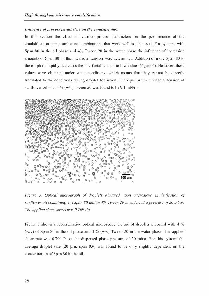
Figure 5. Optical micrograph of droplets obtained upon microsieve emulsification of
sunflower oil containing 4% Span 80 and in 4% Tween 20 in water, at a pressure of 20 mbar.
The applied shear stress was 0.709 Pa.
Figure 5 shows a representative optical microscopy picture of droplets prepared with 4 %
(w/v) of Span 80 in the oil phase and 4 % (w/v) Tween 20 in the water phase. The applied
shear rate was 0.709 Pa at the dispersed phase pressure of 20 mbar. For this system, the
average droplet size (20 μm; span 0.9) was found to be only slightly dependent on the
concentration of Span 80 in the oil.
28

Chapter 2
The effect of using different concentrations of Span 80 on the droplet size and span is shown
in Figure 6. The droplet size decreases with increase in Span 80 concentration in oil, where as
the span remains almost constant. Since all experiments were carried out at the critical
pressure of emulsification (40, 25, 21 and 20 mbar for 1, 2, 3 and 4% of Span 80 in oil
respectively) and at a constant applied shear stress, the decrease in droplet size could be
caused by the enhanced dynamics of the surfactant with the increase of Span 80 concentration
in oil. The droplet to pore diameter ratio was in the range of 3 to 7, which is also expected for
single pore emulsification [13]. This indicates that the emulsification is very stable against
coalescence for all concentrations of Span 80 used in oil. Even upon six days storage of the
prepared emulsions no change in the droplet size and span was observed. It means that the
presence of suitable surfactants, i.e. Span 80 in oil and Tween 20 in water, improves the
emulsion stability due to steric repulsion between both surfactants. Even though a span of 0.8
can be considered as a good size distribution, a much narrower size distribution has been
obtained with SPG-based membrane emulsification, however under different process
conditions [9].
0
10
20
30
40
0 1 2 3 4 50
1
2
3
Span 80 % (w/v)
Droplet diameter (�m)
Span of droplet size ( - )
Figure 6. Average droplet diameter and span upon emulsification with different
concentrations of Span 80 in the dispersed (oil) phase, at the critical pressure of
emulsification and a shear stress of 0.709 Pa. Solid line is droplet diameter; dotted line is
span. Circles represents immediately after preparation and triangles after storage for 6 days.
29
High throughput microsieve emulsification
In a computational fluid dynamic study [22] it was shown that for cylindrical pores of 7 µm,
the resulting droplets have a diameter of about 33 µm (i.e., a ratio of 4.7). To avoid
coalescence between two neighboring droplets, the distance between two adjacent pores
should therefore be at least 5 times the droplet size. However the droplet will get deformed in
the direction of flow during the detachment process. Therefore, considering this deformation,
the distance between the pores should be 7 times the pore diameter. In this way it is only
possible to design and use a microsieve with a maximum porosity of 1.5 %. That a well-
defined emulsion was obtained with the use of a high porosity microsieve, was due to the fact
that in the present system the droplets are quickly protected from coalescence and thus remain
stable, even though they may well press against each other. With the use of a second
surfactant in the dispersed phase the Laplace pressure can be lowered due to a decrease in the
interfacial tension. Therefore, this results in more active pores at corresponding pressures,
yielding higher fluxes.
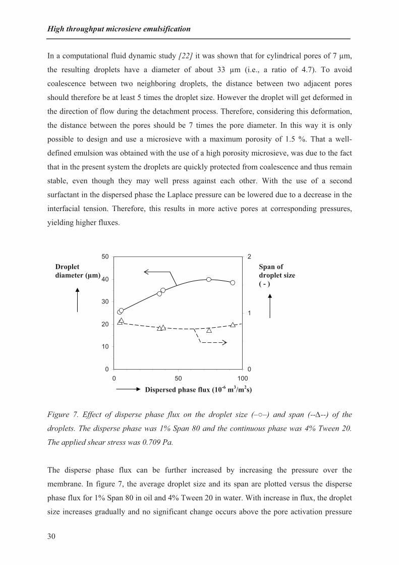
Figure 7. Effect of disperse phase flux on the droplet size (–�–) and span (--�--) of the
droplets. The disperse phase was 1% Span 80 and the continuous phase was 4% Tween 20.
The applied shear stress was 0.709 Pa.
The disperse phase flux can be further increased by increasing the pressure over the
membrane. In figure 7, the average droplet size and its span are plotted versus the disperse
phase flux for 1% Span 80 in oil and 4% Tween 20 in water. With increase in flux, the droplet
size increases gradually and no significant change occurs above the pore activation pressure
Dispersed phase flux (10-6 m3/m2s)
Droplet diameter (�m)
Span of droplet size ( - )
0
10
20
30
50
0 50 1000
1
2
40
30

Chapter 2
(38 mbar). The force or torque balance models (e.g. Peng and Williams [23]) would indicate
that the dispersed phase flux (or the transmembrane pressure) is not important for the droplet
size obtained. However, these models do not take the dynamics of droplet formation into
account. Van der Graaf et al. [24] showed that for a T-shaped microchannel, the flow rate of
the dispersed phased is important, since the droplet detachment takes some time. They showed
that the smallest droplets are produced at low dispersed phase flow rates. At higher dispersed
phase flow rates, the frequency of droplet formation from a single pore increases, and the time
necessary for necking and snap off becomes significant compared to the total droplet
formation time. They also found that the droplet volume could be described by a critical
volume, plus a necking contribution that was more or less proportional to the dispersed phase
flow rate. Examination of figure 7 shows that this description could also apply in our system.
At the pore activation pressure (the Laplace pressure at which emulsification starts), the flux
was 6 x 10⁻⁶ m3/m2s. It was possible to increase the flux of the oil phase up to 92.5 x 10⁻⁶
m3/m2s without significantly changing the span of droplet.
Due to the presence of the large number of pores in the microsieve, it was difficult to observe
or estimate the number of active pores during the emulsification process. Dispersed-phase
fluxes of up to 92.5 x 10⁻⁶ m3/m2s could however be achieved, which is considerably higher
than the value of 6.94 x 10⁻⁶ m3/m2s reported earlier for SPG-based cross-flow emulsification
[25].
Conclusions Coalescence of droplets and wetting of high-porosity silicon nitride microsieve membranes by
the dispersed phase during oil droplet formation, was prevented by adding a suitable
surfactant to the dispersed phase. This leads to stable and narrow size distribution emulsions.
The surfactant in the dispersed phase should exhibit relatively fast adsorption dynamics,
which is more critical when the surfactant in the aqueous continuous phase has slower
dynamics (e.g., Tween 20 compared to SDS). The flux of the disperse phase could be
increased an order of magnitude compared to previous methods, without loss of low span of
the droplets. Thus, use of a high-porosity membrane, in combination with suitable surfactants
in both the dispersed and continuous phases led to a much more effective and efficient
emulsification process.
31

High throughput microsieve emulsification
AcknowledgmentsThis research is carried out within the work package Microengineering of Supramolecular
Structures of the Dutch MicroNed program is also thanked for financial support. The authors
thank Gert Veldhuis of Nanomi for valuable advice regarding the use of the emulsification
module and setup. Aquamarijn is thanked for providing the microsieves. Jos Sewalt from the
Food Process Engineering group, Wageningen, is thanked for technical information regarding
the use of the Malvern mastersizer and Karin Schroën for helpful discussions.
Supplementary information A movie of edible oil in water emulsification with a high porosity microsieve, in the presence
of 4% (w/v) Span 80 in oil and 4% (w/v) Tween 20 in water is available online in the
publication: Journal of Membrane Science, 2010, 347, 1-7
32

Chapter 2
References
[1] M. Saito, L.J. Yin, I. Kobayashi, M. Nakajima, Food Hydrocolloids 2005, 19, 745.
[2] A.S. Utada, E. Lorenceau, D.R. Link, P.D. Kaplan, H.A. Stone, D.A. Weitz, Science 2005, 308,
537.
[3] H. Song , D.L. Chen, R.F. Ismagilov, Angew. Chem. Int. Ed. 2006, 45, 7336.
[4] S. Abraham, E.H. Jeong, T. Arakawa, S. Shoji, K.C. Kim, I. Kim, J.S. Go, Lab on a Chip 2006,
6, 752.
[5] M. Seo, C. Paquet, Z.H. Nie, S.Q. Xu, E. Kumacheva, Soft Matter 2007, 3, 986.
[6] P. Garstecki, M.J. Fuertsman, H.A. Stone, G.M. Whitesides, Lab on a Chip 2006, 6, 437.
[7] L. Shui, A. van den Berg, J.C.T. Eijkel, Lab on a Chip 2009, 9, 795.
[8] M.J. Geerken, T.S. van Zanten, R.G.H. Lammertink, Z. Borneman, W. Nijdam, C.J.M. van Rijn,
M. Wessling, Adv. Engin. Mater., 2004, 6, 749.
[9] G.T. Vladisavljevic, H. Schubert, J. Membr. Sci. 2003, 225, 15.
[10] C.J.M. van Rijn, Nano and micro-engineered membrane technology, Elsevier, Amsterdam 2004,
ISBN 0444514899.
[11] S. Kuiper, C.J.M. van Rijn, W. Nijdam, M.C. Elwenspoek, J. Membr. Sci. 1998, 150, 1.
[12] C.J.M van Rijn, W. Nijdam, Proceedings of the NSTI Nanotechnology conference and trade
show. 2007, 418.
[13] A.J. Abrahamse, R. van Lierop, R.G.M. van der Sman, A. van der Padt, R.M. Boom, J. Membr.
Sci. 2002, 204, 125.
[14] Y. Gu, D. Li, J. Colloid Interface Sci. 2000, 226, 328.
[15] Y. Mine, M. Shimizu, T. Nakashima, Colloids Surf. B: Biointerfaces 1996, 6, 261.
[16] M. Stang, H. Karbstein, H. Schubert, Chem. Eng. Process. 1994, 33, 307.
[17] E. Egidi, G. Gasparini, R.G. Holdich, G.T. Vladisavljevic, S.R. Kosvintsev, J. Membr. Sci. 2008,
323, 414.
[18] I. Kobayashi, M. Nakajima, S. Mukataka, Colloids Surf. A: Physicochem. Eng. Asp. 2003, 229,
33.
[19] W.J. Benton, C.A. Miller, T. Fort, J. Dispersion Sci. Technol. 1982, 3, 1.
[20] J.C. López-Montilla, P.E. Herrera-Morales, S. Pandey, D.O. Shah, J. Dispersion Sci. Technol.
2002, 23, 219.
[21] S. van der Graaf, C.G.P.H Schroën, R.G.M. van der Sman, R.M. Boom, J. Colloid Interface Sci.
2004, 277, 456.
[22] A.J. Abrahamse, A. van der Padt, R.M. Boom, W.B C. de Heij, AIChE J. 2001, 47, 1285.
[23] S.J. Peng, R.A. Williams, Trans. IChemE. 1998, 16, 894.
33

High throughput microsieve emulsification
34
[24] S. van der Graaf, M.L.J. Steegmans, R.G.M. van der Sman, C.G.P.H. Schroën, R.M. Boom,
Colloids Surf. A: Physicochem. Eng. Asp. 2005, 66, 106.
[25] V. Schroder, Herstellen von öl-in-wasser emulsionen mit mikroporosen membranen, PhD-Thesis,
Technische Hochschule, Karlsruhe, 1999.

Chapter 3 Abstract
A simple route is presented to prepare core-shell Eudragit microcapsules through a solvent
extraction method with the use of microsieve emulsification. Droplets from a solution of
Eudragit FS 30D (a commercial copolymer of poly(methyl acrylate-co-methyl methacrylate-
co-methacrylic acid) 7:3:1) and hexadecane in dichloromethane are dispersed into water,
using a micro-engineered membrane with well-defined pores, in a cross-flow setting. The
dichloromethane is extracted from the droplets, which induces demixing in the droplets,
leading to a hexadecane-rich core, and an Eudragit-rich shell. The obtained microcapsules
have a narrow size distribution due to the microsieve emulsification process. The capsules
have a porous shell as shown by SEM and AFM measurements. Their porosity and pore size
is dependent on the ratios of Eudragit and hexadecane in the dispersed phase. At pH 7.1 and
above Eudragit (FS 30D) dissolves in water; this pH change is used to release the contents of
the microcapsule.
Porous microcapsule formation with
microsieve emulsification
This Chapter has been published as: Nagesh A. Wagdare, Antonius T. M. Marcelis, Remko M. Boom and Cees J. M. van Rijn, Porous microcapsule formation with microsieve emulsification, Journal of Colloid and Interface Science, 2011, 355, 453-457.

Porous microcapsules with microsieve emulsification
IntroductionSensitive, volatile or reactive additives such as drugs, biocultures, flavors and vitamins can be
turned into stable functional ingredients through microencapsulation. With careful fine-tuning
[1-3] of the microcapsules, new ingredients can be developed with a large variety of
properties and wide applicability. The oral delivery of components that are susceptible to
degradation [4-7], such as peptides, nanovectors, aptamers, enzymes, living cells and
probiotics in microcapsules has substantially increased in the past decades. Several strategies
have been developed to counter-balance the digestive influence of the stomach (pH 2-3) and
bile salts in the duodenum (pH 6-6.5) by increasing the stability and activity of the
encapsulated ingredients. Especially the lower gastrointestinal (GI) tract from the small
intestine (pH 6.5-7.0) to the colon (pH 7.0-8.0) has been used as site to target these agents.
Microcapsules are built up of a core and a shell, and the release of the core material is co-
determined by the permeability [3, 8] of the capsule wall. Since the size of the capsule is
important for the rate of release, control over the size and size distribution of microcapsules is
a crucial factor. Various studies have been performed on membrane emulsification for
production of emulsions, particles and microcapsules [9-13]. We recently investigated
conditions for high throughput production of well-controlled oil-water emulsions using cross-
flow membrane emulsification with high porosity micro-engineered microsieves [14].
Microsieve emulsification has the additional advantage that microcapsules can be prepared
with a minimum of energy consumption.
Different approaches have been employed in the past to prepare microcapsules with tunable
size, permeability and mechanical strength [2, 3, 15, 16]. Phase separation is an approach to
prepare oil-core polymer-shell capsules [17-26], in which a non-volatile poor solvent (alkane)
is added to a polymer solution in a volatile organic solvent, which is then emulsified in an
aqueous phase to form an oil-water emulsion. The solvent diffuses out of the droplets, through
the continuous phase, and evaporates at the surface of the bath. The extraction of the solvent
from the droplet induces instability in the droplet. An inner core droplet of the poor solvent is
formed, while the solution around this inner core becomes even more highly concentrated in
the polymer. Thus a polymeric shell is created around the inner droplet which ultimately
solidifies by gelation, crystallization or glassification. Although fabrication of core-shell
microcapsules by phase separation is well known, capsule formation with porous shell
membranes is not very well understood. Because the capsule formation process starts with an
emulsion droplet, precise control over the emulsion droplet size should lead to well-defined
36

Chapter 3
microcapsules with a narrow size distribution and thus similar properties. In this study cross-
flow microsieve emulsification is used to generate an oil-water emulsion with a narrow size
distribution. The emulsified droplets consist of Eudragit as a hydrophilic polymer, hexadecane
as oil and dichloromethane as solvent. Eudragit FS 30D is a poly(methyl acrylate-co-methyl
methacrylate-co-methacrylic acid) copolymer with monomer ratios of 7:3:1. It is insoluble in
water below pH 7 and dissolves above pH 7. Since Eudragit is relatively hydrophilic, a porous
shell is formed. The influence of polymer and oil concentration on the phase separation
process that leads to the core-shell microcapsules is investigated. Furthermore, the pH-
triggered dissolution process of the polymer shell, releasing the inner oil droplets, was
studied. The results of this model study can lead to the development of microcapsules with
pH-triggered release under physiologically relevant conditions.
Materials and Methods
Materials
An aqueous dispersion of Eudragit FS 30 D (ED) was obtained as a gift from Evonik
Industries. This dispersion was freeze-dried to remove the water. The resulting powder was
then used to prepare the capsules. Dichloromethane (DCM; Merck) was used as volatile
organic solvent to dissolve the polymer and hexadecane (Merck), which was also used as a
poor solvent for the polymer. A 1 % aqueous sodium dodecyl sulfate (SDS; Fluka) solution
(pH 5) was used as continuous phase for the emulsification.
Microengineered membrane, emulsification device and microcapsule formation
Details of the membrane and emulsification set-up used have already been published [14].
The membrane used was a 5x5 mm microchip with a silicon nitride membrane with an
effective area of 3x3 mm. The thickness of membrane was 1 μm, and contained 5 μm
diameter pores with distances between the pores of 10 μm, yielding a porosity of 30 %. The
microsieves were treated with air plasma to obtain a hydrophilic surface. Then they were
fixed into the membrane holder with an epoxy glue. The disperse phase was a solution of
Eudragit in DCM containing hexadecane; 1% SDS in water was used as continuous phase. All
experiments were carried out at a pressure of 30 mbar (capillary pressure is 23 mbar) and a
shear stress of 0.71 Pa imposed by the cross-flow of the continuous phase. At these conditions
control over the disperse phase flux and resulting droplet formation was good. At higher
37

Porous microcapsules with microsieve emulsification
pressures it becomes difficult to control the droplet formation. The Eudragit polymer was first
dissolved in DCM. To this solution the poor solvent hexadecane was added. This mixture was
then pressed through a high porosity microsieve into a 1% aqueous SDS solution to form an
oil in water emulsion by the method as described before [14].
Characterization of the microcapsules
Scanning electron microscopy: The aqueous dispersions of the capsules were filtered through
a Nuclepore polycarbonate membrane and then dried at ambient conditions. Subsequently, the
capsules were sputter-coated with gold/palladium and visualized along with the filter
membrane by a field emission scanning electron microscope (JEOL 6300 F, Tokyo, Japan) at
a working distance of 8 mm, with SE detection at 5 kV. All images were recorded digitally
and were optimized and resized by Adobe Photoshop 7.0.
Confocal laser scanning microscopy: The cavity for the sample was prepared by cutting a
rectangular hole in a piece of parafilm and putting it on a glass slide. This was then covered
with a glass cover slip fixed firmly to the glass slide by applying nail polish. Then the capsule
dispersion was added from the side opening with the use of a micropipette. The sample was
then investigated with a confocal laser scanning microscope (Zeiss LSM 510 Meta); green
fluorescence protein was excited at 488 nm and Nile red at 633 nm.
Atomic force microscope: The aqueous dispersions of the capsules were filtered through a
regenerated cellulose polymeric filter membrane and subsequently dried in air. Then the
surface of the capsule was scanned by tapping-mode atomic force microscopy (AFM; Asylum
Research MFP-3D SA AFM). Height images were obtained in AC mode in air using
NSC35/AIBS ultra sharp cantilevers (MikroMasch Europe).
Results and discussion
Microcapsule formation and size determination
The average size of the droplet formed immediately after microsieve emulsification is 53 μm
with a coefficient of variation of 12% as estimated from movie pictures made of the
emulsification. During the microcapsule formation, at the low concentrations used, the DCM
is miscible with water. Therefore, it migrates from the droplets towards the external water
phase. As hexadecane is neither compatible with water nor polymer and causes liquid-liquid
demixing between polymer and hexadecane, the oil tends to nucleate in the middle of the
38

Chapter 3
capsule and the polymer starts to gelate around the oil droplet. This subsequently results in the
formation of hexadecane core/polymer shell microcapsules. The remaining DCM in the water
phase is slowly evaporated by stirring in contact with air. The obtained microcapsules (figure
1) have a relatively narrow size distribution (figure 2), with an average diameter of 30 μm and
a coefficient of variation of 15%. The diameter is larger than would be expected based on the
initial concentrations of Eudragit and hexadecane. The main reason for this is that the
Eudragit is hydrophilic and becomes swollen in the aqueous environment. An additional
reason could be that as soon as the droplet starts forming from the microsieve pore, DCM
already starts to go to the aqueous phase, thus increasing the concentrations of Eudragit and
hexadecane in the initial DCM droplet.
Figure 1. Optical microscope picture of Eudragit capsules prepared at a 2% polymer and 2%
hexadecane initial concentration.
10 15 20 25 30 35 40 45 500
5
10
15
20
25
30
35
40
volu
me
(%)
diameter (µm)
Figure 2. Size distribution of Eudragit microcapsules determined from optical microscopy;
capsules were prepared at a 2% polymer and 2% hexadecane initial concentration.
39

Porous microcapsules with microsieve emulsification
Phase separation studies with CLSM
Figure 3 shows confocal microscopy pictures of a capsule, in which the hexadecane is stained
with hydrophobic Nile Red and the Eudragit with green fluorescent protein (GFP). As is
clearly seen, the hexadecane is mainly present in the centre of the capsules, while the Eudragit
forms a shell around it; however, it can be seen that some hexadecane is also present in the
shell. Observation of these microcapsules with optical microscopy (figure 1) does not provide
information on the presence of oil in the shell, however investigation with CLSM confirms
the presence of oil in the shell, probably in the form of tiny droplets. The phase separation
process starts at the surface of the droplets. Since the concentrations of both Eudragit and
hexadecane increase, both components start to phase separate from the solution, and
hexadecane droplets can get trapped in the developing Eudragit shell. The number and size of
these droplets will depend on the ratios and initial concentrations of both Eudragit and
hexadecane. An implication of the presence of hexadecane droplets in the shell on the
formation of a porous shell of the capsule is discussed in the next section.
a) b) c)
Figure 3. Microcapsules prepared from a 4% polymer and 8% hexadecane solution in DCM
a) excitation of the green fluorescence protein b) excitation of the Nile red c) excitation of
both Nile red and green fluorescent protein. (For color picture see Appendix on page number
101).
Influence of initial composition on microcapsule morphology as studied with SEM and
AFM
The phase separation process results in microcapsules with either a porous or a dense
membrane depending on the conditions used. This is clear from scanning electron microscopy
(SEM) pictures of the microcapsules.
40

Chapter 3
a) b) c)
Figure 4. SEM images of microcapsules prepared by phase separation at different initial
polymer and hexadecane concentrations, a) 2% polymer and 15% hexadecane, b) 3%
polymer and 15% hexadecane, c) 4% polymer and 8% hexadecane. Scale bar is 10 µm.
Figure 4 shows SEM images of microcapsules prepared at different polymer and hexadecane
initial concentrations. It is seen that using a small ratio of polymer over hexadecane results in
porous shells, which seem relatively weak (figure 4a). This could be caused by coalescence of
the small trapped hexadecane droplets in the relative thin Eudragit shell giving larger pores, or
by channels formed in the shell by DCM diffusing out of the core or a combination of these
processes. Using more polymer relative to hexadecane results in a lower porosity and smaller
pores (figure 4b), and almost complete disappearance of the pores at sufficiently high polymer
concentrations. Earlier studies indicate that pore formation can be caused either by in-
diffusion of water and/or out-diffusion of DCM [18, 27] during the capsule formation
process. It is also possible that the pores in the capsule shell are formed by residual amounts
of hexadecane which did not have time enough to diffuse into the core of the droplet during
the phase separation process [28]. This is supported by the fact that an increase in
concentration of hexadecane, relative to the polymer concentration, leads to more pores
(which would therefore be made up of hexadecane droplets). Therefore, upon increasing the
polymer to hexadecane ratio (in figure 4 going from a) to c)) the shell surface morphology
changes from porous to dense. An increase in hexadecane concentration at the periphery of
the shell may result in coalescence of several hexadecane droplets, and thus bigger pores upon
increasing the hexadecane concentration. The overlap image of the confocal laser scanning
microscopy in figure 3c indeed shows the presence of small amounts of hexadecane at the
edge of the shell.
The surface of the microcapsule prepared at an initial 4% polymer and 8% hexadecane
(compare Figure 4c) was also investigated with Atomic Force Microscopy (AFM). Since the
size of microcapsules is quite big (30 μm) for AFM, only a part of the capsule surface could
41

Porous microcapsules with microsieve emulsification
be scanned. Figure 5 shows an AFM image of the capsule surface, which clearly shows the
curved surface having pores with sizes of around 100 nanometers, which corresponds nicely
with the electron microscopy results (Figure 4c).
Figure 5. AFM image of a capsule surface prepared from an initial 4% polymer and 8%
hexadecane solution in DCM.
Dissolution studies of microcapsule shells at different pH
An interesting property of the Eudragit FS 30D used in this study is that it is insoluble in
water below pH 7 and readily dissolves above pH 7. Therefore, it can potentially be used for
oral delivery to the extreme lower part of the gastrointestinal tract. The pH-dependent
behavior of microcapsules prepared from an initial 4% Eudragit and 8% hexadecane solution
in DCM was investigated by optical microscopy.
42
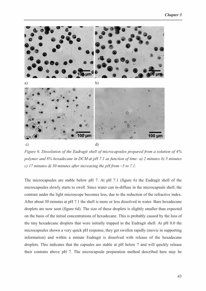
Chapter 3
a) b)
c) d)
Figure 6. Dissolution of the Eudragit shell of microcapsules prepared from a solution of 4%
polymer and 8% hexadecane in DCM at pH 7.1 as function of time: a) 2 minutes b) 5 minutes
c) 17 minutes d) 30 minutes after increasing the pH from ~5 to 7.1.
The microcapsules are stable below pH 7. At pH 7.1 (figure 6) the Eudragit shell of the
microcapsules slowly starts to swell. Since water can in-diffuse in the microcapsule shell, the
contrast under the light microscope becomes less, due to the reduction of the refractive index.
After about 30 minutes at pH 7.1 the shell is more or less dissolved in water. Bare hexadecane
droplets are now seen (figure 6d). The size of these droplets is slightly smaller than expected
on the basis of the initial concentrations of hexadecane. This is probably caused by the loss of
the tiny hexadecane droplets that were initially trapped in the Eudragit shell. At pH 8.0 the
microcapsules shown a very quick pH response, they get swollen rapidly (movie in supporting
information) and within a minute Eudragit is dissolved with release of the hexadecane
droplets. This indicates that the capsules are stable at pH below 7 and will quickly release
their contents above pH 7. The microcapsule preparation method described here may be
43

Porous microcapsules with microsieve emulsification
interesting for encapsulation and controlled release of oil-soluble active ingredients for
delivery to lower gastrointestinal tract.
ConclusionsMicrocapsules with a narrow size distribution of around 30 micron were prepared from
Eudragit and hexadecane dissolved in DCM, using cross-flow emulsification with a micro-
engineered microsieve membrane. Due to a phase-separation process by which the DCM is
removed, a hexadecane core is formed in the microcapsules, surrounded by an Eudragit-rich
shell. At polymer concentrations which are low relative to the concentration of hexadecane,
the shells were found to be porous. Increasing the polymer concentration, relative to the oil
concentration, resulted in a reduction of the porosity and pore size. The capsules are stable at
pH lower than 7, whereas the oil core was released in half an hour at pH 7.1 and within a
minute at pH 8.0 due to dissolution of Eudragit shell.
The present study indicates that with a careful choice of polymer, oil and solvent, and their
relative concentrations, microcapsules can be obtained with a well-defined core-shell
morphology. Depending on the concentrations of both polymer and oil, the phase separation
processes differ. At higher concentrations of polymer, the tiny oil droplets that are captured in
the forming Eudragit shell cannot coalesce anymore and therefore lead to small pores. The
present study shows that core-shell microcapsules can be made with a porous shell of which
pore size and porosity can be easily tuned. This may influence the permeability properties of
the shell. Combined with the microsieve emulsification process and the pH-triggered
dissolution of the Eudragit shell, this research may lead to the development of microcapsules
with special release properties.
Acknowledgments The Dutch MicroNed program is thanked for financial support. Aquamarijn is thanked for
providing the microsieves and Evonik Pharmacy Inc. for the Eudragit FS 30D sample.
Adriaan van Aelst for SEM measurements and Marcel Giesbers for AFM measurements.
Supporting information A movie of the dissolution of the Eudragit shell at pH 8 for microcapsules prepared from an
initial 4% Eudragit and 8% hexadecane solution in DCM is available online in the
publication: Journal of Colloid and Interface Science, 2011, 355, 453-457.
44

Chapter 3
References
[1] S.H. Im, U. Jeong, Y. Xia, Nat. Mater. 2005, 4, 671.
[2] K.J. Pekarek, J.S. Jacob, E. Mathiowitz, Nature 1994, 367, 258.
[3] A.D. Dinsmore, M. F. Hsu, M.G. Nikolaides, M. Marquez, A.R. Bausch, D.A. Weitz, Science
2002, 298, 1006.
[4] R.T. Bartus, M.A. Tracy; D. F. Emerich, S.E. Zale, Science 1998, 281, 1161.
[5] T.M.S. Chang, Science 1964, 146, 524.
[6] H. Song, D.L. Chen, R.F. Ismagilov, Angew. Chem. Int. Ed. 2006, 45, 7336.
[7] Y. Wang, S. Gao; W. H. Ye, H.S. Yoon, Y.Y. Yang, Nat. Mater. 2006, 5, 791.
[8] D.A. Edwards, J. Hanes; G. Caponetti, J. Hrkach, A. Ben-Jebria, M.L. Eskew, J. Mintzes, D.
Deaver, N. Lotan, R. Langer, Science 1997, 276, 1868.
[9] N. Aryanti, R.A. Williams, R. Hou; G.T. Vladisavljevi�, Desalination 2006, 200, 572.
[10] L.Y. Chu, R. Xie, J.H. Zhu, W.M. Chen, T. Yamaguchi, S.I. Nakao, J. Colloid Interface Sci.
2003, 265, 187.
[11] S.R. Kosvintsev, G. Gasparini, R.G. Holdich, J. Membrane Sci. 2008, 313, 182.
[12] G.T. Vladisavljevi�, H. Schubert, J. Membrane Sci. 2003, 225, 15.
[13] R.A. Williams, Chem. Eng. Res. Des. 1998, 76, 902.
[14] N.A. Wagdare, A.T.M. Marcelis, O.B. Ho, R.M. Boom, C.J.M. van Rijn, J. Membrane Sci.
2010, 347, 1.
[15] H.N. Yow, A.F. Routh, Soft Matter 2008, 4, 2080.
[16] J.W. Kim, A. Fernández-Nieves, N. Dan, A.S. Utada, M. Marquez, D.A. Weitz, Nano Lett.
2007, 7, 2876.
[17] H. Sawalha, Y. Fan, K. Schro�n, R. Boom, J. Membrane Sci. 2008, 325, 665.
[18] F.M. Lavergne, D. Cot, F. Ganachaud, Langmuir 2007, 23, 6744.
[19] P.J. Dowding, R. Atkin; B. Vincent, P. Bouillot, Langmuir 2004, 20, 11374.
[20] P.J. Dowding, R. Atkin, B. Vincent, P. Bouillot, Langmuir 2005, 21, 5278.
[21] E. Kamio, S. Yonemura, T. Ono, H. Yoshizawa, Langmuir 2008, 24, 13287.
[22] H. Sawalha, K. Schro�n, R. Boom, J. Appl. Polym. Sci. 2008, 107, 82.
[23] H.N. Yow, A.F. Routh, Soft Matter 2006, 2, 940.
[24] J. Han, G. Song, R. Guo, Adv. Mater. 2006, 18, 3140.
[25] Z. Ao, Z. Yang, J. Wang, G. Zhang, T. Ngai, Langmuir 2009, 25, 2572.
[26] K. Kooiman, M.R. Böhmer, M. Emmer, H.J. Vos, C. Chlon, W.T. Shi, C.S. Hall, S. H.P.M. de
Winter, K. Schro�n, M. Versluis, N. de Jong, A. van Wamel, J. Control. Release 2009, 133,
109.
45

Porous microcapsules with microsieve emulsification
46
[27] H. Sawalha, N. Purwanti, A. Rinzema, K. Schro�n, R. Boom, J. Membrane Sci. 2008, 310,
484.
[28] R.D. Deegan, O. Bakajin, T.F. Dupont, G. Huber, S.R. Nagel, T.A. Witten, Nature 1997, 389,
827.

Chapter 4 Abstract
Microcapsules were prepared by microsieve membrane cross flow emulsification of
Eudragit FS 30D/dichloromethane/edible oil mixtures in water, and subsequent phase
separation induced by extraction of the dichloromethane through an aqueous phase. For
long-chain triglycerides and jojoba oil, core-shell particles were obtained with the oil as
core, surrounded by a shell of Eudragit. Medium chain triglyceride (MCT oil) was
encapsulated as relatively small droplets in the Eudragit matrix. The morphology of the
formed capsules was investigated with optical and SEM microscopy. Extraction of the oil
from the core-shell capsules with hexane resulted in hollow Eudragit capsules with porous
shells. It was shown that the differences are related to the compatibility of the oils with the
shell-forming Eudragit. An oil with poor compatibility yields microcapsules with a dense
Eudragit shell on a single oil droplet as the core; oils having better compatibility yield
porous Eudragit spheres with several oil droplets trapped inside.
Hollow capsules: influence of the encapsulated
oil on the capsule morphology
This Chapter has been published as: Nagesh A. Wagdare, Antonius T. M. Marcelis, Remko M. Boom and Cees J. M. van Rijn, Microcapsules with a pH responsive polymer: influence of the encapsulated oil on capsule morphology, Colloids and surfaces B: Biointerfaces, 2011, Article in press.

Hollow capsules: influence of the encapsulated oil on capsule morphology
IntroductionMicrocapsules are useful ingredients of many products in daily life such as cosmetics,
functional foods, and pharmaceuticals [1]. Microcapsules with a polymeric shell surrounding
a core filled with oil [2-4] are interesting for encapsulation and delivery of oil-soluble
components. Many flavors and fragrances, but also antioxidants, vitamins and
pharmaceuticals are oil-soluble and sensitive to the acidic conditions in the stomach which
limits their applicability for oral delivery [5-7]. Therefore, providing the microcapsules with a
pH-sensitive polymer shell could improve the delivery and bioavailability of these substances
[7-9].
Microcapsules can be prepared by a wide range of methods, including spray drying or
chilling, extrusion and phase separation. The last method allows for the preparation of very
small microcapsules that should not influence the taste of the product, while still ensuring a
good polymeric shell around the encapsulated component. In phase separation, a polymer
solution is emulsified in a non-solvent. The solvent inside the droplet is then slowly extracted.
The to-be-encapsulated component forms a separate phase at some point in the process,
usually in the middle of the solidifying droplet. The morphologies and properties of the
resulting capsules depend on factors like the extraction rate of the solvent, demixing time and
the phase behavior of the system [10].
Several strategies have been employed in the past to prepare capsules by changing one or
more components of the system. The use of an amorphous polymer results in slow
solidification and transition into a glassy, dense shell; a semi-crystalline polymer may lead to
faster solidification and to porous shells. If the non-solvent surrounding the droplets is more
compatible with the solvent, i.e. has a better solubility, the solvent is extracted more quickly,
which results in faster demixing and this can possibly influence the morphology of the
resulting capsules [11, 12].
The removal rate or extraction of the solvent is a very important parameter for microcapsule
formation. This is not only influenced by the non-solvent but also by the type of encapsulated
component (oil) that is used. Depending on the compatibility of the polymer and the oil, the
demixing rates vary, which leads to different shell morphologies, for example dense with a
single oil core, or a porous shell that gradually opens up to a porous core [13-15]. Finally, oils
that are relatively well compatible with the shell-forming polymer will swell the material,
which will influence the physical properties of the polymer phase, such as its thermal and
mechanical properties [14].
48

Chapter 4
Encapsulation of materials within a shell of stimuli-responsive polymers (e.g. by pH or
temperature) have gained specific interest for controlled release applications [16-18].
Eudragit FS 30D is a commercial random copolymer of poly (methyl acrylate-co-methyl
methacrylate-co-methacrylic acid) 7:3:1, which is used extensively for enteric coating
applications. The polymer contains a certain percentage of carboxylate groups, which makes
them water-soluble above pH 7.0. These properties have been used to obtain sustained
delivery of vitamin C by encapsulating in an Eudragit shell with slightly different properties
(Eudragit RL) [19]. Control over the permeability properties is important and this has been
achieved with a variety of routes, e.g. by adsorption of colloidal Eudragit particles on an
emulsion droplet [20].
Phase separation is a simpler route to prepare porous microcapsules of Eudragit. Eudragit is
dissolved in a low concentration in dichloromethane, together a certain amount of the to-be-
encapsulated oil. At these low concentrations, these two components are both dissolved in the
dichloromethane. This solution is then emulsified in water. The dichloromethane dissolves in
low concentrations in the water, thus slow diffusion from the droplet occurs into the aqueous
phase and finally the dichloromethane can evaporate at the air-water surface of the system. As
the droplets slowly lose solvent they become more concentrated in Eudragit and oil. At some
point, the Eudragit and oil are not miscible anymore, and under the right conditions will
demix into a shell of Eudragit, and a core consisting of oil.
Since Eudragit protects the encapsulated oil from an acidic environment and dissolves at a pH
above 7.0, it is a potential candidate for use in oral delivery of oil-soluble or oil-dispersible
components to the extreme lower part of the gastrointestinal (GI) tract. Since the final
morphology depends on the miscibility of Eudragit and oil, it is important to chart the
response of the formation process to different oils. This process can also be used to
encapsulate lipophilic components inside the oil core and influence their delivery [21, 22].
Once the capsules are formed, removal of the oil core by solvent extraction results in hollow
capsules. These hollow capsules are interesting candidates for ultrasound-mediated delivery
systems, due to the presence of gas inside these capsules. Use of different oils is expected to
result in different morphologies of the hollow capsules [13, 14, 23-26]. In this paper we
discuss the preparation of Eudragit capsules with different types of oils starting with the
formation of the primary droplets using microsieve emulsification. This method yields
relatively narrow size-dispersed microcapsules under mild conditions [15]. Based on the
results with different types of oil, we gain insight into the relation between oil properties and
49

Hollow capsules: influence of the encapsulated oil on capsule morphology
the resulting microcapsules and thus obtain understanding about which functional oils can
successfully be encapsulated in Eudragit capsules and what type of morphologies are
obtained. Furthermore, extraction of the encapsulated oil from the microcapsule with a
suitable solvent results in hollow pH-sensitive microcapsules. Conditions are described for
obtaining these hollow and multi-compartment microcapsules of Eudragit.
Materials and methods
Materials
An aqueous dispersion of Eudragit FS 30 D (ED) was obtained as a gift from Evonik
Industries. This dispersion was freeze-dried to remove the water. The resulting polymer
powder (Eudragit) was then used to prepare the capsules. Dichloromethane (DCM; Merck)
was used as volatile organic solvent to dissolve the Eudragit and the different oils. The
dispersed phase for the emulsification was prepared by first dissolving the Eudragit polymer
in DCM and then adding the poor solvent (oil). The final concentrations of both Eudragit and
the oil in DCM were 3 % (w/v).
Medium chain triglyceride (MCT oil; Migylol 812 N; SASOL GmbH), olive oil (Fluka),
jojoba oil (Sigma Aldrich), Sunflower oil (obtained from a local super market) and coconut
oil (Sigma Aldrich) were used as obtained. A 1 % aqueous sodium dodecyl sulfate (SDS;
Fluka) solution was used as the continuous phase for the emulsification.
Microengineered membrane emulsification and encapsulation
The details of the membrane and emulsification set-up used have already been published [27].
All emulsification experiments were carried out at 25 °C and at a disperse phase pressure of
30 mbar and a shear rate 0.71 Pa of the continuous phase. This dispersed phase mixture was
pressed through a 5 μm high-porosity microsieve into a 1 % aqueous SDS solution to form an
oil-in-water emulsion. The obtained dispersion was slowly stirred overnight in an open
container to evaporate the remaining DCM.
Preparation of hollow capsules
The microcapsules were filtered and washed several times with water to remove the SDS.
After drying in contact with air, the capsules were suspended in hexane and left standing
overnight and shaken manually a few times. Then hexane was removed by pipette and
50

Chapter 4
replaced several times with fresh hexane. After removal of the hexane, the capsules were
dried in air at ambient conditions.
Characterization of the capsules
Optical microscopy: An Olympus BH2 microscope was used to obtain optical images. For
this, aqueous suspensions of the capsules were put on a glass slide. The microscope was
equipped with a Moticam 2000 camera and the images were retrieved and stored with the
Motic Image Plus program. The scale bar was introduced with the image J program.
Scanning electron microscope of microcapsules: The hollow capsules were placed on a
cellulose acetate filter membrane after which the membranes were sputter-coated with 3 nm
gold and mounted in the sample holder without glue. Samples were analyzed at 2 kV at room
temperature in a field emission Auger microprobe (JEOL, JAMP-9500F). To observe the
internal structure; capsules were glued between two adhesion tapes after which the two tapes
were separated to fracture some of the capsules.
Results and discussion The phase separation will depend on the mutual interactions between the polymer and the oil
[28]. Therefore, different oils were chosen with different chain lengths and polarities to see
how these factors influence the interaction between polymer and oil. All capsules were
prepared using the same concentrations of polymer and oil (3%), so that only the properties of
the oil influence the final structure of the microcapsules rather than a variation in
concentrations. For possible use of these microcapsules as vehicles for delivery to the lower
intestinal tract the pH-sensitive Eudragit and digestible oils were chosen as model
compounds. The triglycerides all have three ester groups, but differ in molecular weight
(about 400-500 for MCT oil and 900-1000 for sunflower, coconut or olive oil). Jojoba oil is a
mixture of monoesters with a molecular weight of about 550-650. Because it is a monoester it
is more apolar than the triglycerides.
Figure 1 shows optical microscopy images of the microcapsules prepared with the different
oils. As observed before [15], microcapsules with an average size of about 30 μm and a
coefficient of variation of 15% are formed under these conditions. The variation in size seems
limited. The capsules prepared with MCT (figure 1a) shows several tiny MCT oil droplets
enclosed within the polymer shell, which are not clearly visible through the polymer shell.
51
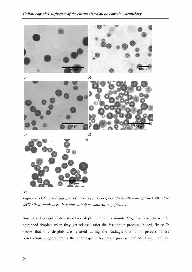
Hollow capsules: influence of the encapsulated oil on capsule morphology
a) b)
c) d)
e)
Figure 1. Optical micrographs of microcapsules prepared from 3% Eudragit and 3% oil a)
MCT oil; b) sunflower oil; c) olive oil; d) coconut oil; e) jojoba oil.
Since the Eudragit matrix dissolves at pH 8 within a minute [15], its easier to see the
entrapped droplets when they get released after the dissolution process. Indeed, figure 2b
shows that tiny droplets are released during the Eudragit dissolution process. These
observations suggest that in the microcapsule formation process with MCT oil, small oil
52
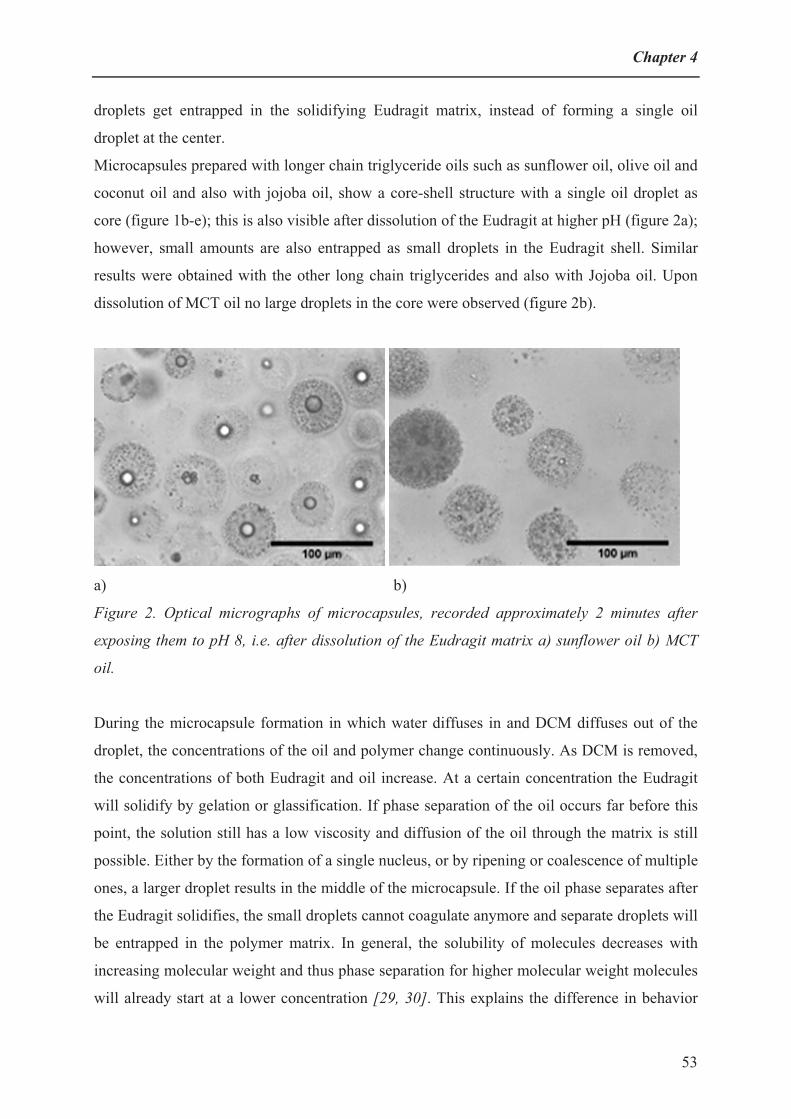
Chapter 4
droplets get entrapped in the solidifying Eudragit matrix, instead of forming a single oil
droplet at the center.
Microcapsules prepared with longer chain triglyceride oils such as sunflower oil, olive oil and
coconut oil and also with jojoba oil, show a core-shell structure with a single oil droplet as
core (figure 1b-e); this is also visible after dissolution of the Eudragit at higher pH (figure 2a);
however, small amounts are also entrapped as small droplets in the Eudragit shell. Similar
results were obtained with the other long chain triglycerides and also with Jojoba oil. Upon
dissolution of MCT oil no large droplets in the core were observed (figure 2b).
a) b)
Figure 2. Optical micrographs of microcapsules, recorded approximately 2 minutes after
exposing them to pH 8, i.e. after dissolution of the Eudragit matrix a) sunflower oil b) MCT
oil.
During the microcapsule formation in which water diffuses in and DCM diffuses out of the
droplet, the concentrations of the oil and polymer change continuously. As DCM is removed,
the concentrations of both Eudragit and oil increase. At a certain concentration the Eudragit
will solidify by gelation or glassification. If phase separation of the oil occurs far before this
point, the solution still has a low viscosity and diffusion of the oil through the matrix is still
possible. Either by the formation of a single nucleus, or by ripening or coalescence of multiple
ones, a larger droplet results in the middle of the microcapsule. If the oil phase separates after
the Eudragit solidifies, the small droplets cannot coagulate anymore and separate droplets will
be entrapped in the polymer matrix. In general, the solubility of molecules decreases with
increasing molecular weight and thus phase separation for higher molecular weight molecules
will already start at a lower concentration [29, 30]. This explains the difference in behavior
53

Hollow capsules: influence of the encapsulated oil on capsule morphology
between the long chain triglycerides and MCT oil. Although jojoba oil has a similar molecular
weight as MCT oil, it is expected to phase separate earlier due to its more apolar nature.
For microsphere formation with suspension polymerization in the presence of different oils, it
is known that the phase separation process can be related to the degree of incompatibility or
immiscibility of the different oils with the shell-forming polymer and this determines the
structure and morphology of the formed microcapsules [31]. The degree of incompatibility
depends on the molecular weight of the oil: the higher the molecular weight the more
incompatible, and the polarity: a more apolar oil is more incompatible. Here we observe
similar behavior for the solvent extraction-induced phase separation. With long chain
vegetable oils like sunflower or olive oil, the phase separation is occurring earlier as
compared to medium chain triglyceride oil. Jojoba oil, which has only one ester group, is
more apolar than triglycerides and therefore is less compatible with Eudragit and forms a
single core-shell structure, despite having a lower molecular weight than the long chain
triglycerides.
Figure 3. Schematic representation of the preparation of empty microcapsules with different
structures formed in Eudragit microcapsules with use of different oils.
During the phase separation-induced capsule formation, oil-rich and Eudragit-rich phases will
start to separate after bringing the solution in contact with water. The polar polymer-rich
54

Chapter 4
phase will start to migrate towards the external aqueous phase, whereas the apolar oil-rich
phase will tend to move towards the core of the particle. This induces concentration gradients
in the particles, that also change with time. This means that depending on the distance to the
surface the phase separation process results in different morphologies. If the molecular weight
of the triglyceride vegetable oil is high enough or if it is apolar enough as in the case of jojoba
oil, phase separation occurs relatively early and most of the forming droplets have ample time
to nucleate in the center. For the more polar low molecular weight oil, phase separation occurs
later in the extraction process where the polymer already has started to solidify, thus the
coagulation of the forming oil droplets is less complete in this case (Figure 3).
Since these processes are also dependent on the relative concentrations of the two components
and time, the resulting internal morphology is dependent on the distance to the surface of the
microcapsule. This is the reason that even for the high molecular weight oils some small oil
droplets become entrapped in the Eudragit shell. It is to be expected that an oil that is even
less compatible with the Eudragit than the long-chain oils, will show less or even no droplets
in the shell.
Removal of the oil template could be accomplished by a simple process of exposing the dried
capsules to a solvent that can extract the oil without influencing the polymer shell morphology
(Figure 3). This is possible by exposing the capsules to hexane to extract the oil from the
capsules. This process results in the formation of hollow capsules which can be clearly
imaged with scanning electron microscopy.
a) b)
Figure 4. SEM images of hollow microcapsules a) Microcapsules prepared with jojoba oil
scale bar (10 µm) b) Surface morphology of microcapsule prepared with sunflower oil scale
bar (1µm).
55

Hollow capsules: influence of the encapsulated oil on capsule morphology
Figure 4a shows a SEM image of hollow capsules after extraction of jojoba oil. Most of them
have an intact shell, even after exposure to vacuum. A few capsules have a broken shell,
indicating that the capsules are indeed hollow. Other capsules look inflated, which is also an
indication that they are hollow. Figure 4b shows a magnified image of a hollow capsule after
extraction of sunflower oil. A porous surface is seen with some holes. We expect that these
holes are related to the slight porosity of the shell as was noted earlier [15]. The presence of
holes in the initial shell of the capsule also allows the hexane to diffuse in the microcapsules
and to extract the oil from the core thus leaving a cavity in the center of the microcapsule
[32].
a) b)
Figure 5. SEM images of broken hollow microcapsules, scale bar (10 µm) a) Microcapsules
prepared with sunflower oil b) Microcapsules prepared with MCT oil.
Based on the optical microscopy images it is expected that microcapsules derived from high
molecular weight oils are hollow, whereas microcapsules with multiple compartments are
expected from particles derived from the lower molecular weight MCT oil. Pulling apart two
adhesive tapes that have microcapsules between them results in breaking of some of them.
Figure 5a shows a SEM image of capsules after removal of sunflower oil. The depicted
capsule has a single large void. Figure 5b shows capsules after removal of MCT oil. In this
case multi-compartment capsules are formed. These SEM images confirm the findings with
optical microscopy. Treatment of the capsules with adhesive tape in order to break them
resulted only in a few capsules that actually broke. This indicates that the capsules are not
very fragile and can withstand some physical stress.
56

Chapter 4
The internal structure of these hollow and multi-compartment capsules by extraction of the oil
core is completely dependent on the initial morphology of these microcapsules. Therefore, by
designing the desired initial structure inside the capsule with the use of different types of oil
allows for the precise fabrication of desired hollow and multi-compartment capsules.
ConclusionsEudragit microcapsules were prepared by emulsifying droplets of a dilute solution of a shell-
forming polymer (Eudragit) and an oil that was to be encapsulated in water. By doing so, the
solvent (dichloromethane) slowly extracted from the droplets, which induced demixing
between oil and polymer, creating a solid shell of Eudragit around one or more oil droplets.
For the droplet preparation, microsieve cross-flow membrane emulsification was used, since
this yielded narrowly-dispersed microcapsules with an average size of about 30 μm.
The morphology of the microcapsules depends on the compatibility between the oil that is
encapsulated, and the Eudragit polymer. Use of long chain length oils such as sunflower oil,
olive oil and coconut oil, which have poor compatibility with the Eudragit, mainly yield
microcapsules with a single encapsulated oil droplet covered with an Eudragit-rich shell. On
the other hand, microcapsules prepared with a relatively short chain length oil such as
medium chain triglyceride oil, which has a better compatibility with the Eudragit, results in
capsules with many small oil droplets encapsulated in an Eudragit-matrix. Jojoba oil, which is
more apolar than triglycerides, also gave mainly single oil droplet microcapsules.
The final microcapsule morphology was thus shown to be dependent on the interaction
between oil and polymer. Poor interaction will already induce demixing between oil and
polymer at low polymer concentrations, allowing for the formation of one single oil droplet at
the centre. Good interaction will delay the demixing to the stage at which the polymer
concentration is already quite high, which will inhibit the transport of the oil to a single
droplet and this leads to the formation of many small droplet dispersed in an Eudragit matrix.
Optical microscopy of the microcapsules and SEM investigations of microcapsules from
which the oil was removed confirm this hypothesis.
In summary, a method is presented for microencapsulation of food grade oils in well-defined
microcapsules, and a rationale is given of the microcapsule morphology as function of the
compatibility of the materials. We believe that this research may lead to the development of
rational design of hollow or filled microcapsules that are useful for encapsulating active
ingredients and releasing them by a pH trigger [32-34].
57

Hollow capsules: influence of the encapsulated oil on capsule morphology
Acknowledgements The Dutch MicroNed program is thanked for financial support of this research. Aquamarijn is
thanked for providing the microsieves and Evonik Pharmacy Inc. for the Eudragit FS 30D
sample. Marcel Giesbers is thanked for Auger SEM measurements.
58

Chapter 4
References
[1] S. Freiberg, X. X. Zhu, Int. J. Pharm. 2004, 282, 1.
[2] P. J. Dowding, R. Atkin, B. Vincent, P. Bouillot, Langmuir 2004, 20, 11374.
[3] P. J. Dowding, R. Atkin, B. Vincent, P. Bouillot, Langmuir 2005, 21, 5278.
[4] K. Kooiman, M. R. Böhmer, M. Emmer, H. J. Vos, C. Chlon, W. T. Shi, C. S. Hall, S. H. P.
M. de Winter, K. Schro�n, M. Versluis, N. de Jong, A. van Wamel, J. Control. Release 2009,
133, 109.
[5] M. C. Jones, H. Gao, J. C. Leroux, J. Control. Release 2008, 132, 208.
[6] P. Simerska, P. M. Moyle, C. Olive, I. Toth, Curr. Drug Delivery 2009, 6, 347.
[7] L. Trichard, E. Fattal, M. Besnard, A. Bochot, J. Control. Release 2007, 122, 47.
[8] J. Y. Hong, J. K. Kim, Y. K. Song, J. S. Park, C. K. Kim, J. Control. Release 2006, 110, 332.
[9] Y. Zhang, Z. Zhi, T. Jiang, J. Zhang, Z. Wang, S. Wang, J. Control. Release 2010, 145, 257.
[10] H. Sawalha, K. Schro�n, R. Boom, J. Appl. Polym. Sci. 2007, 104, 959.
[11] H. Sawalha, Y. Fan, K. Schro�n, R. Boom, J. Membrane Sci. 2008, 325, 665.
[12] I. M. Wienk, R. M. Boom, M. A. M. Beerlage, A. M. W. Bulte, C. A. Smolders, H.
Strathmann, J. Membrane Sci. 1996, 113, 361.
[13] H. Sawalha, K. Schro�n, R. Boom, Polym. Eng. Sci. 2010, 50, 513.
[14] H. Sawalha, K. Schro�n, R. Boom, AIChE J. 2009, 55, 2827.
[15] N. A. Wagdare, A. T. M. Marcelis, R. M. Boom, C. J. M. van Rijn, J. Colloid Interface Sci.
2011, 355, 453.
[16] G. Ozaydin-Ince, K. K. Gleason, M. C. Demirel, Soft Matter 2011, 7, 638.
[17] M. A. C. Stuart, W. T. S. Huck, J. Genzer, M. Müller, C. Ober, M. Stamm, G. B. Sukhorukov,
I. Szleifer, V. V. Tsukruk, M. Urban, F. Winnik, S. Zauscher, I. Luzinov, S. Minko, Nat.
Mater. 2010, 9, 101.
[18] Q. Yuan, O. J. Cayre, S. Fujii, S. P. Armes, R. A. Williams, S. Biggs, Langmuir 2010, 26,
18408.
[19] E. Esposito, F. Cervellati, E. Menegatti, C. Nastruzzi, R. Cortesi, Int. J. Pharm. 2002, 242,
329.
[20] A. San Miguel, J. Scrimgeour, J. E. Curtis, S. H. Behrens, Soft Matter 2010, 6, 3163.
[21] D. J. McClements, Y. Li, Adv. Colloid and Interface Sci. 2010, 159, 213.
[22] H. S. Ribeiro, J. M. M. Guerrero, K. Briviba, G. Rechkemmer, H. P. Schuchmann, H.
Schubert, J. Agri. Food Chem. 2006, 54, 9366.
[23] S. Jacobsen, H. G. Fritz, Polym. Eng. Sci. 1999, 39, 1303.
[24] H. Sawalha, K. Schro�n, R. Boom, J. Agri. Food Chem. 2008, 107, 82.
[25] E. G. Schutt, D. H. Klein, R. M. Mattrey, J. G. Riess, Angew. Chem. Int. Ed. 2003, 42, 3218.
59

Hollow capsules: influence of the encapsulated oil on capsule morphology
60
[26] M. A. Wheatley, J. D. Lathia, K. L. Oum, Biomacromolecules 2007, 8, 516.
[27] N. A. Wagdare, A. T. M. Marcelis, O. B. Ho, R. M. Boom, C. J. M. van Rijn, J. Membrane
Sci., 347, 1.
[28] F. M. Lavergne, D. Cot, F. Ganachaud, Langmuir 2007, 23, 6744.
[29] H. Sawalha, N. Purwanti, A. Rinzema, K. Schro�n, R. Boom, J. Membrane Sci. 2008, 310,
484.
[30] S. Stassen, N. Nihant, V. Martin, C. Grandfils, R. Jérôme, P. Teyssié, Polymer 1994, 35, 777.
[31] D. X. Hao, F. L. Gong, G. H. Hu, J. D. Lei, G. H. Ma, Z. G. Su, Polymer 2009, 50, 3188.
[32] M. Y. Ma, Y. J. Zhu, L. Li, S. W. Cao, J. Mater. Chem. 2008, 18, 2722.
[33] S. H. Im, U. Jeong, Y. Xia, Nat. Mater. 2005, 4, 671.
[34] M. Delcea, A. Yashchenok, K. Videnova, O. Kreft, H. Möhwald, A. G. Skirtach, Macro.
Biosci. 2010, 10, 465.

Chapter 5 Abstract
Microspheres from PMMA (polymethyl methacrylate) and Eudragit FS 30D (a commercial
copolymer of poly(methyl acrylate-co-methyl methacrylate-co-methacrylic acid) 7:3:1) were
prepared using microsieve emulsification. A mixture of these polymers in dichloromethane
was dispersed into water, leading to extraction of DCM in water and the formation of
microspheres with a PMMA core and a partially demixed Eudragit shell. With a higher ratio
of Eudragit to PMMA, more and bigger pores can be seen on the surface of the microspheres.
Eudragit can be removed from the microspheres under alkaline conditions. Depending on the
initial Eudragit to PMMA ratio, PMMA microspheres with different surface morphologies are
obtained. At low Eudragit concentrations microspheres with a crumpled surface are formed,
while at higher Eudragit concentrations microspheres are formed with a core to which
dendritic PMMA structures are attached. At even higher Eudragit concentrations the
microspheres obtained after dissolving the Eudragit show a nanorough surface.
Structured microspheres from polymer blends
This chapter has been submitted for publication as: Nagesh A. Wagdare, Jacob Baggerman,Antonius T. M. Marcelis, Remko M. Boom and Cees J. M. van Rijn, Polymer microspheres with structured surfaces.

Structured microspheres from polymer blends
IntroductionMicrospheres are considered for use in separation processes, biorecognition [1], for
immobilization of catalysts [2-4] and as potential vehicles in drug delivery applications [5].
Since their properties are strongly dependent on their size, shape and morphology, precise
control over these aspects is of major concern [6]. Additionally, microspheres have been
prepared with a wide range of polymers and polymer blends. The nature of these polymers
and the morphologies of the microspheres have a significant impact on the release rates and
profiles. The material properties can for example be modified by blending with other
polymeric materials [7]. The type of polymer and its interaction with solvent and non-solvent
determines the formed morphologies of membranes [8, 9]. This concept can also be applied in
microsphere formation. If during formation of microspheres, phase separation between the
two polymers occurs in such a way that one polymer completely spreads over the other,
double-walled microspheres are formed [10]. With a careful choice and use of enthalpic
interactions, chain lengths, polymer surface tension and spreading coefficients, well-defined,
double-walled microspheres can be designed and obtained [11]. Several combinations of
polymers have been used in literature to prepare double-walled microspheres. For example,
polylactide-co-glycolide (PLG) / polyorthoester (POE) mixtures have been used for
preparation of microspheres with a PLG core and a POE shell [12]. Double-walled
microspheres were also obtained from polylactic acid / poly[1,3-bis(p-carboxyphenoxy-
propane)-co-sebacic anhydride] mixtures, where complete phase separation occurred.
However, for polylactic acid / POE mixtures, hybrid microspheres were obtained, in which
the POE did not completely encapsulate the core and with polylactic acid / polystyrene
mixtures microspheres were obtained that did not show any coverage of the core [10]. A more
detailed study was performed with PLG / poly[1,6-bis(p-carboxyphenoxyhexane)] mixtures,
where different ratios of core and shell-forming polymers were used. For this system it was
found that phase separation between the two polymers and the formation of double-walled
microspheres was incomplete when a low amount of shell-forming polymer was used [13].
Though fabrication of double-walled microspheres through the use of mixtures of different
polymers is known, there is still no complete understanding of the phase separation process
that determines the shape and morphology of the obtained double-walled microspheres.
Especially, the shape and morphology of the core, obtained after dissolution of the outer shell
polymer still requires investigation. This study aims at exploring the morphology of core-shell
microspheres using blends of two different polymers in different ratios.
62

Chapter 5
Blends of enteric polymers like Eudragit and non-enteric polymers are interesting as materials
for controlled release delivery systems [7, 14]. Eudragit is a class of (meth)acrylate-based
copolymers that is used extensively for enteric coatings. Since they contain a certain
percentage of carboxylic acid groups, they are insoluble at low pH (<7), but soluble at higher
pH. For diffusion-controlled release, properties like shell thickness and porosity are important.
A recent technique to obtain porous films with a co-continuous structure uses a blend of two
polymers from which one polymer is later selectively leached out [15]. This allows one to
prepare membranes with highly interconnected pores with control over porosity, pore size and
surface morphology [16-19]. In this paper we describe the use of this technique for the
preparation of microspheres from poly methyl methacrylate (PMMA) and Eudragit FS 30 D
blends by microsieve emulsification, since microsieve emulsification is a low-energy
consuming process that yields microspheres with a rather narrow size distribution and this
process can easily be upscaled. Eudragit is not miscible with PMMA; therefore phase
separation between PMMA and Eudragit is expected after bringing droplets of this solution in
contact with a non-solvent. The internal structures obtained upon phase separation of the
mixture will depend on the ratio of two polymers. The Eudragit used is soluble in water above
pH 7.0 [20], and it is therefore selectively leached out of the initial microspheres under
alkaline conditions, yielding PMMA microspheres with different surface morphologies that
are investigated with different microscopic techniques.
Materials and Methods
Materials
An aqueous dispersion of Eudragit FS 30 D (ED; MW 220,000; Tg 40 °C) was obtained as a
gift from Evonik Industries. This dispersion was freeze-dried to remove the water. The
resulting polymer was then used to prepare the microspheres. Poly(methyl methacrylate
(PMMA; MW 120,000; Tg 105 °C) was obtained from Aldrich. Dichloromethane (DCM;
Merck) was used as a volatile organic solvent. A 1 % aqueous sodium dodecyl sulfate (SDS;
Fluka) solution was used as continuous phase for the emulsification.
Microengineered membrane, emulsification device and microsphere preparation
Details of the microsieve membrane and the emulsification set-up used were already
published [21]. Eudragit and PMMA were dissolved in DCM separately in different
63

Structured microspheres from polymer blends
concentrations and then mixed to obtain the disperse phase with the desired concentrations
and ratios. This polymer mixture in DCM was then pressed through a 5 μm high porosity
microsieve into the continuous phase consisting of a 1% SDS solution in water at pH 6.5 to
form an oil in water emulsion. All experiments were carried out at a disperse phase pressure
of 30 mbar and a continuous phase shear rate of 0.71 Pa. Since the amount of water is large as
compared to DCM, DCM will be extracted to the water phase and evaporates into air at the
water surface. The phase separation process between PMMA and Eudragit occurs by liquid-
liquid demixing and gelation, to form a PMMA core and an Eudragit-rich shell (Figure 1).
Once the microspheres have been formed they are analyzed at pH 6.5 (preparation condition).
For the removal of the Eudragit polymers, the microspheres were first washed with water and
then brought to pH 8.0 and kept at this pH for at least 1 day. Before visualization, the buffer
containing the dissolved Eudragit was washed away with water.
Characterization of the microspheres
Optical microscopy: The suspension of microspheres was spread on a glass slide and observed
visually. Images of the microspheres were made using an Olympus BH2 microscope.
Scanning electron microscope: A drop of an aqueous suspension of the microspheres was put
on a Nuclepore polycarbonate membrane (Costar) with 5 �m holes. These membranes were
placed on filter paper to remove the fluid through the membrane, leaving the spheres on the
top side of the membrane. After air drying the membrane was glued onto a sample holder by
carbon adhesive tabs (EMS, Washington, USA) and subsequently sputter-coated with 3 nm
tungsten (MED 020, Leica, Vienna, Austria). Samples were analyzed at 3 kV at room
temperature in a field emission scanning electron microscope (Magellan 400, FEI, Eindhoven,
the Netherlands). Images were digitally recorded.
Atomic force microscope: The aqueous dispersions of the microspheres were filtered through
a regenerated cellulose polymeric filter membrane (Whatman, RC55, 0.45 μm pore size) and
subsequently dried in air. Then the surface of the capsule was scanned by tapping-mode
atomic force microscopy (Asylum Research MFP-3D SA AFM). Height images were
obtained with Tap 150 DLC silicon cantilevers (Budgetsensors) in AC mode in air.
DSC: The thermograms were obtained using a TA Q1000 instrument with a TZero technology
system.
64

Chapter 5
Results and Discussion
Microsphere formation
The two polymers (PMMA and Eudragit) are expected to be immiscible due to their
difference in chemical nature. To confirm this, the glass transition temperature of a polymer
film prepared by evaporating DCM from a mixture of 1.5% PMMA and 1.5% Eudragit
solutions was measured by DSC. Two different Tg-values were obtained, one around 40 °C
for Eudragit and one around 105 °C for PMMA, which are the values expected for the pure
polymers. This indicates that these polymers are indeed molecularly immiscible [17]. As the
microsphere preparation starts with a low concentrations of both polymers in DCM (typically
5 wt% or lower in total), we start with a homogeneous solution. However, after bringing this
polymer mixture solution in contact with a nonsolvent (water), the DCM is extracted from the
droplets, the polymer concentrations rise, and phase separation between the two polymers will
occur, which will ultimately be stopped by gelation and glassification of an amorphous
polymer (figure 1) [20]. The microspheres resulting from the microsieve emulsification had
an average size of about 20 μm and a coefficient of variation of about 20%, which is slightly
higher than previously reported for a similar system [20]; this is probably caused by slight
wetting of the microsieve surface during the emulsification process. Interestingly, the average
size did not change much when the Eudragit concentration was increased from 1.5 to 3.5%.
Upon removal of the Eudragit shell from the obtained microspheres at pH 8, the average sizes
of the resulting cores decreased as expected. The sizes of the cores became smaller when the
initial Eudragit concentrations were higher.
Microsieve emulsification process
pH 8.0
PMMA microspherePMMA/ED microsphere
Figure 1. Microsphere preparation using microsieve emulsification. The Eudragit (ED) shell
of the resulting PMMA core / Eudragit shell double-walled microspheres dissolves upon
bringing the pH to 8.0, resulting in PMMA microspheres with different surface morphologies.
(For color picture see Appendix on page number 101).
65

Structured microspheres from polymer blends
Studies with optical microscopy
Figure 2 a) shows an optical microscopy image of microspheres prepared from a mixture of
1.5 wt% PMMA and 1.5 wt% Eudragit before leaching out Eudragit. No clear core shell
structure could be seen. However, upon increasing the amount of Eudragit to 3.5% in the
initial mixture the encapsulated PMMA spheres within the Eudragit shells became clearly
visible (figure 2b). This shows that the composition of PMMA and Eudragit in the initial
mixture influences the formation of the core-shell morphology.
a) b)
Figure 2. Optical microscopy images of microspheres at pH 6.5 (before leaching out
Eudragit) a) PMMA 1.5% and Eudragit 1.5% b) PMMA 1.5% and Eudragit 3.5% .
Figure 3 shows optical microscopy pictures of microspheres at pH 8.0 (after leaching out
Eudragit) obtained from different ratios of PMMA and Eudragit in the initial mixture.
Microspheres prepared from 1.5% PMMA and 1.5% Eudragit (figure 3a) show a slightly
crumpled morphology (see discussion of SEM images in later section). With an increase in
amount of Eudragit to 2.5-3% (figure 3b and 3c) the microspheres show a distinct core, but
also a highly swollen outer shell. At 3.5% of Eudragit in the mixture, no swollen corona is
seen anymore and only a small core is left (figure 3d).
A reason that the shell did not completely dissolve for the microspheres prepared from 2.5%
and 3% of Eudragit, may be due to the fact that with larger amounts of Eudragit, some of the
PMMA will be initially solubilized in the forming Eudragit shell, and will later on in the
formation process precipitate in the form of small but physically connected PMMA domains
in the Eudragit shell. After dissolution of the Eudragit at pH 8.0, the PMMA domains form
dendritic structures on the surface of the core and in contact with water the shell swells. These
observations with optical microscopy were confirmed with SEM and AFM and will be
66

Chapter 5
discussed in next section. Also the effect of composition on polymer demixing in the
microsphere will be discussed.
a) b)
c) d)
Figure 3. Optical microscopy pictures of microspheres at pH 8.0. Microspheres prepared
from a) 1.5% PMMA and 1.5% Eudragit, b) 1.5% PMMA and 2.5% Eudragit, c) 1.5% PMMA
and 3% Eudragit, d) 1.5% PMMA and 3.5% Eudragit.
SEM-study of effect of composition on microsphere morphology
Figure 4 shows SEM images of the dried microspheres obtained from different ratios of
PMMA and Eudragit in the initial DCM solution at pH 6.5 and at pH 8.0 (after dissolving the
Eudragit). The shells of the microspheres prepared at pH 6.5 appear porous at all
concentrations of Eudragit (figure 4 a, c, e and g). Upon increasing the amount of Eudragit it
is seen that the number and size of the pores at the surface increases. For membrane formation
by non-solvent induced phase separation the enhanced interaction of polymer with non-
solvent increases the porosity of the outer surface [22]. During the formation of the
67

Structured microspheres from polymer blends
microspheres a phase separation process occurs, resulting in the formation of a core rich in
PMMA and a shell rich in Eudragit. The dissolution of DCM in water at the surface of the
droplets causes the PMMA to move to the core of the droplet that is still rich in DCM and the
hydrophilic Eudragit to move to the surface of the droplet where it phase separates. Water
diffuses into the droplet due to the favorable interaction with the hydrophilic Eudragit. On the
other hand, the DCM that is still present in the droplet needs to diffuse out through the
forming Eudragit shell. This will lead to the formation of DCM-rich channels [20] through
the Eudragit layer, that may initially still contain some PMMA. In the later stages of the
microsphere formation, the polymers in these channels will phase separate from the
disappearing DCM solvent into an Eudragit matrix containing small trapped nodules of
PMMA. Similar behavior was observed during the formation of double-walled microspheres
with poly(L-lactic acid) (PLLA) shells and poly(D,L-lactic-co-glycolic acid) (PLGA) cores
[23].
a) b)
c) d)
68
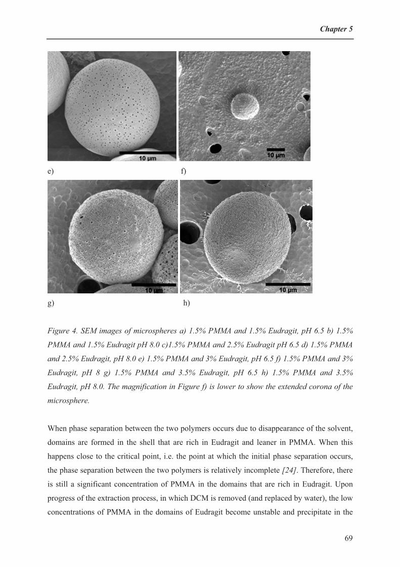
Chapter 5
e) f)
g) h)
Figure 4. SEM images of microspheres a) 1.5% PMMA and 1.5% Eudragit, pH 6.5 b) 1.5%
PMMA and 1.5% Eudragit pH 8.0 c)1.5% PMMA and 2.5% Eudragit pH 6.5 d) 1.5% PMMA
and 2.5% Eudragit, pH 8.0 e) 1.5% PMMA and 3% Eudragit, pH 6.5 f) 1.5% PMMA and 3%
Eudragit, pH 8 g) 1.5% PMMA and 3.5% Eudragit, pH 6.5 h) 1.5% PMMA and 3.5%
Eudragit, pH 8.0. The magnification in Figure f) is lower to show the extended corona of the
microsphere.
When phase separation between the two polymers occurs due to disappearance of the solvent,
domains are formed in the shell that are rich in Eudragit and leaner in PMMA. When this
happens close to the critical point, i.e. the point at which the initial phase separation occurs,
the phase separation between the two polymers is relatively incomplete [24]. Therefore, there
is still a significant concentration of PMMA in the domains that are rich in Eudragit. Upon
progress of the extraction process, in which DCM is removed (and replaced by water), the low
concentrations of PMMA in the domains of Eudragit become unstable and precipitate in the
69

Structured microspheres from polymer blends
form of small trapped spheres. This behavior is also known in other fields (e.g. membrane
formation by phase separation) [25].
These complex phase separation processes will lead to different domains in the shell; some
containing almost pure but water-rich Eudragit and some containing Eudragit with trapped
PMMA spheres. During drying the water-rich Eudragit domains will shrink and leave holes or
pores that are visible with SEM and also with AFM as will be discussed later.
Upon increasing the pH to 8.0, the surface morphology of the microspheres changes
significantly due to the dissolution of the Eudragit. In control experiments it was seen that
Eudragit rapidly dissolves at pH 8.0. Typically, pure Eudragit microspheres of this size
completely dissolve within tens of seconds at this pH. The core-shell microspheres
investigated here, were kept at pH 8.0 for at least one day before microscopic investigation.
A dried microsphere from 1.5% PMMA and 1.5% Eudragit, obtained after dissolution of the
Eudragit (Figure 4b) has a crumpled surface with indentations. We expect that the initial shell
of these microspheres still contained relatively large PMMA domains, mostly connected to
the core structure, since they were the channels through which the DCM diffused out of the
core. Removal of the Eudragit domains leaves empty pockets resulting in an irregular surface
of the remaining microspheres.
Microspheres obtained from initial mixtures containing 2.5% or 3% Eudragit show cores upon
dissolution of the Eudragit, whose surfaces are covered with a swollen corona, as clearly seen
with optical microscopy (Figures 3b and c). Also the SEM pictures show microspheres with a
core that is surrounded by an extended corona of less dense fiber-like material (figures 4d and
4f). The fact that these microspheres have a extended corona even after exposure to pH 8,
indicates that this shell consists of PMMA. During the dissolution process the Eudragit is
removed from the microsphere. The PMMA in the shell was presumably mostly present in the
channels that served to diffuse out the DCM as explained before. Upon dissolution at pH 8.0,
the pure Eudragit domains and the Eudragit in the mixed domains were removed and the
PMMA spheres became physically aggregated into fibrous structures connected to the core,
which give the microspheres a swollen appearance. At present it is unclear whether the
physical aggregation was already present or occurs during the dissolution process.
AFM-studies on the core-shell morphology of the microspheres
Optical microscopy (figure 3c) and SEM (figure 4f) already showed that microspheres
obtained from an initial concentration of 1.5% PMMA and 3% Eudragit, after bringing them
70

Chapter 5
to pH 8.0, have a PMMA core surrounded by an open extended corona. For comparison with
the SEM pictures, additional AFM studies were performed on these microspheres.
a) b)
c) d)
Figure 5. AFM images of a microsphere prepared from 1.5% PMMA and 3% Eudragit a) 3D
height image of a microsphere surface at pH 6.5 b) 3D height image of a microsphere core at
pH 8.0 c) 2D height image of a microsphere corona (nodules loosely packed around PMMA
core) at pH 8.0 d) section profile of c).
Figure 5a shows a 3D AFM height image of a microsphere at pH 6.5, i.e. before dissolving
the Eudragit, which indeed shows a porous surface with pore sizes of about 100 nm, without
any nodular structure. Figure 5b shows the 3D AFM height image of the core of the
microsphere at pH 8.0, i.e. after dissolving the Eudragit. This picture shows that the core of
71

Structured microspheres from polymer blends
the microsphere is rather smooth with hardly any structure. Figure 5c shows a zoomed-in
image of the material of the corona of the microsphere. It is seen that the corona consists of
aggregates of small nodular particles of about 50 nm with a roughness of around 20 nm
(figure 5d). These are small particles formed by the phase separation between the two
polymers and will be discussed in the next section in detail.
SEM and AFM studies on the nodular structure formation on the microspheres
The microspheres, prepared from an initial concentration of 1.5% PMMA and 3.5% Eudragit,
have an increased porosity (figure 4g) at pH 6.5, due to the higher amount of Eudragit. After
exposure of the microspheres to pH 8.0, the Eudragit shell material was removed (figure 4h)
and no core-shell morphology is observed anymore (figure 3d) and some small particles are
visible on the microsphere surface. Figure 6a is a zoomed-in image of figure 4h, which clearly
shows the presence of densely packed polymeric nodules on the microsphere surface with a
size of about 100 nm. Due to the low concentration of PMMA in this system, it can be
expected that the residual PMMA in the channels through which the DCM diffused out only
very small isolated spheres formed. During the dissolution process of the Eudragit these small
PMMA spheres partly precipitated on the core surface and became physically attached there.
a) b)
Figure 6. a) SEM image and b) 3D topographical AFM image of a microsphere surface at
1.5% PMMA and 3.5% Eudragit, pH 8.0 (i.e. after dissolving Eudragit).
Similar nodular structures have also been observed during the preparation of polyethersulfone
membranes in the presence of hydrophilic polyvinylpyrrolidone additives [25], but there has
72

Chapter 5
been a long standing debate on whether they are real, or whether they represent an artifact
created by the sample preparation procedure for SEM. Detailed information about the surface
structures can also be obtained from AFM. An advantage of AFM as compared to SEM is that
additional sample preparation, such as a complete removal of water and the use of a contrast-
enhancing metal coating is not necessary. Furthermore, the measurements can be carried out
at ambient conditions, which can be essential for retaining the original information about the
surface morphology [26]. Figure 6b is a 3D-height image of the surface of a microsphere
prepared at an initial concentration of 1.5% PMMA and 3.5% Eudragit after leaching out the
Eudragit at pH 8. A nodular structure can clearly be seen, even without sputtering. The fact
that we also see particles with a size of around 100 nm is an indication that the nodules
aggregate on the surface of microsphere. Even some bigger aggregates of around 0.5 - 1 μm
can be seen, which might be supernodular aggregates. This is more clearly seen in the AFM
image than in the SEM image. Fujh et al. [27] observed similar nodular structures and nodular
aggregate structures for commercial PMMA hollow fiber membranes. A mechanism was
proposed by Khulbe et al. for nodular structure formation of poly(2,6-dimethyl-1,4-phenylene
oxide) (PPO) membranes [28]. They suggested that a nodule is made up of a combination of
several macromolecules [29] and that combination of several nodules results in nodular
aggregates [30]. Further combinations of these nodular aggregates then in turn result in
supernodular aggregate structures. The observation with SEM and AFM of similar structures
on the surface of microspheres at pH 8, prepared from an initial concentration of 1.5%
PMMA and 3.5% Eudragit, suggest a similar mechanism. The free space between the nodules
may have beneficial permeation properties for components to be encapsulated, such as drugs.
It was shown that for a PPO ultrafiltration membrane, the permeability of gasses through the
membrane [31] depended on the surface roughness.
Blending of PMMA and Eudragit results in microspheres with different core-shell structures
which depend on the initial composition of the mixture. These microspheres are stable in
aqueous solution below pH 7.0. After bringing these microspheres to pH 8.0 the Eudragit
dissolves to leave PMMA microspheres which show different surface structures, depending
on the initial composition. This type of structures or morphologies of microspheres may be
used for a wide range of applications in controlled release. Most likely they can also be
obtained when using different polymer blends and different relative compositions.
73
Structured microspheres from polymer blends
ConclusionsMicrospheres were prepared from blends of PMMA and Eudragit by the use of microsieve
emulsification. These microspheres consist of a PMMA core inside an Eudragit-rich shell.
Variation in the initial composition of PMMA and Eudragit leads to variation in the core and
shell size. After selectively removing the Eudragit at pH 8, PMMA-rich microspheres were
formed. The surface morphology of the obtained PMMA microspheres was strongly
influenced by the composition of the initial PMMA and Eudragit mixtures.
These microspheres, prepared from PMMA and Eudragit mixtures, are porous due to
diffusion of water into the Eudragit shell. As the amount of Eudragit is increased, a thicker
and more porous outer shell is formed due to the enhanced interaction of water with Eudragit.
After dissolution and removal of the Eudragit, different structures of the core surface are
formed, such as a crumpled irregular surface, a fiber-like swollen corona and a surface
covered with nodular structures, simply by changing the amounts of PMMA and Eudragit in
the initial mixture. These structures are formed as a result of phase separation processes,
during demixing of the two polymers. Therefore, by combining microsieve emulsification
with a solvent extraction induced demixing in polymers, microspheres can be produced with
well-determined size, shape and surface morphology.
Acknowledgments The Dutch MicroNed program is thanked for financial support and Aquamarijn for providing
the microsieves and Evonik Pharmacy for providing an Eudragit FS 30 D sample. Adriaan
van Aelst and Tiny Franssen-Verheijen from WEMC are thanked for help with the SEM
analyses and Yogesh Deshmukh from Technical University Eindhoven for DSC
measurements.
74
Chapter 5
References
[1] A. Pfaff, L. Barner, A. H. E. Müller, A. M. Granville, European Polym. J. 2011, 47, 805.
[2] N. Welsch, A. Wittemann, M. Ballauff, J. Phy. Chem. B 2009, 113, 16039.
[3] S. Phadtare, A. Kumar, V. P. Vinod, C. Dash, D. V. Palaskar, M. Rao, P. G. Shukla, S.
Sivaram, M. Sastry, Chem. Mater. 2003, 15, 1944.
[4] V. P. Vinod, S. Shinde, V. D'Britto, P. G. Shukla, M. Rao, Biotech. Prog. 2006, 22, 1585.
[5] Y. Han, D. Shchukin, J. Yang, C. R. Simon, H. Fuchs, H. Möhwald, ACS Nano 2010, 4, 2838.
[6] Q. Xu, M. Hashimoto, T. T. Dang, T. Hoare, D. S. Kohane, G. M. Whitesides, R. Langer, D.
G. Anderson, H. David, Small 2009, 5, 1575.
[7] F. Siepmann, J. Siepmann, M. Walther, R. J. MacRae, R. Bodmeier, J. Control. Release 2008,
125, 1.
[8] M. Amirilargani, E. Saljoughi, T. Mohammadi, M. R. Moghbeli, Polym. Eng. Sci. 2010, 50,
885.
[9] R. A. Zoppi, S. Contant, E. A. R. Duek, F. R. Marques, M. L. F. Wada, S. P. Nunes, Polymer
1999, 40, 3275.
[10] K. J. Pekarek, J. S. Jacob, E. Mathiowitz, Nature 1994, 367, 258.
[11] E. J. Pollauf, D. W. Pack, Biomaterials 2006, 27, 2898.
[12] Y. Y. Yang, M. Shi, S. H. Goh, S. M. Moochhala, S. Ng, J. Heller, J. Control. Release 2003,
88, 201.
[13] C. Berkland, E. Pollauf, D. W. Pack, K. Kim, J. Control. Release 2004, 96, 101.
[14] P. A. Thomas, T. Padmaja, M. G. Kulkarni, J. Control. Release 1997, 43, 273.
[15] P. Salehi, P. Sarazin, B. D. Favis, Biomacromolecules 2008, 9, 1131.
[16] P. Sarazin, B. D. Favis, Biomacromolecules 2003, 4, 1669.
[17] P. Sarazin, X. Roy, B. D. Favis, Biomaterials 2004, 25, 5965.
[18] S. Steinmann, W. Gronski, C. Friedrich, Polymer 2001, 42, 6619.
[19] R. C. Willemse, Polymer 1999, 40, 2175.
[20] N. A. Wagdare, A. T. M. Marcelis, R. M. Boom, C. J. M. van Rijn, J. Colloid and Interface
Sci. 2011, 355, 453.
[21] N. A. Wagdare, A. T. M. Marcelis, O. Boen Ho, R. M. Boom, C. J. M. van Rijn, J. Membrane
Sci. 2010, 347, 1.
[22] H. Matsuyama, Y. Takida, T. Maki, M. Teramoto, Polymer 2002, 43, 5243.
[23] T. H. Lee, J. Wang, C. H. Wang, J. Control. Release 2002, 83, 437.
[24] C. A. Smolders, A. J. Reuvers, R. M. Boom, I. M. Wienk, J. Membrane Sci. 1992, 73, 259.
[25] R. M. Boom, I. M. Wienk, T. van den Boomgaard, C. A. Smolders, J. Membrane Sci. 1992,
73, 277.
75
Structured microspheres from polymer blends
76
[26] S. Walheim, M. Böltau, J. Mlynek, G. Krausch, U. Steiner, Macromolecules 1997, 30, 4995.
[27] Y. Fujh, H. Iwatani, S. Kigoshi, Polymer J. 1992, 24, 737.
[28] K. C. Khulbe, T. Matsuura, J. Membrane Sci. 2000, 171, 273.
[29] R. E. Kesting, J. Appl. Polym. Sci. 1990, 41, 2739.
[30] K. C. Khulbe, C. Y. Feng, T. Matsuura, D. C. Mosqueada-Jimenaez, M. Rafat, D. Kingston,
R. M. Narbaitz, M. Khayet, J. Appl. Polym. Sci. 2007, 104, 710.
[31] K. C. Khulbe, T. Matsuura, S. H. Noh, J. Membrane Sci. 1998, 145, 243.

Chapter 6 Abstract
This chapter starts with a discussion of the results of the experimental chapters. After that,
each topic covered in this thesis is discussed in general terms by comparison with existing
literature. In the last part of this chapter an outlook of the research is presented. Further
improvements in the emulsification process and material combinations for obtaining desired
microcapsules and microspheres are described. Some possible industrial applications are
mentioned.
Discussion and outlook

Discussion and outlook
The objective of the research reported in this thesis was to determine the conditions for the
preparation of microcapsules and microspheres for oral delivery of active ingredients that are
sensitive to acidic conditions. The microcapsules or microspheres for such applications
require a shell having specific properties for targeted delivery to the lower gastrointestinal
tract. Besides the material properties of the shell, the uniformity and shell thickness are major
determinants for the controlled release properties.
The microsieve emulsification technique was expected to yield microcapsules and
microspheres with narrow size distributions. Phase separation is an elegant method to prepare
microcapsules and microspheres with controlled shell morphologies. Therefore, a
combination of phase separation processes and microsieve emulsification was thought to be a
good approach to obtain structured microcapsules and microspheres with desired size and
surface morphology.
In Chapter 2 emulsification with a high-porosity silicon nitride micro-engineered membrane
is described. Coalescence of droplets and wetting of high-porosity silicon nitride microsieve
membranes by the dispersed phase during oil droplet formation was prevented by adding a
suitable surfactant to the dispersed phase. This leads to stable and narrow size distribution
emulsions. The surfactant in the dispersed phase should exhibit relatively fast adsorption
dynamics, which is more critical when the surfactant in the aqueous continuous phase has
slower dynamics (e.g. Tween 20 compared to SDS). The flux of the disperse phase could be
increased an order of magnitude compared to previous methods, without loss of low span of
the droplets. Thus, use of a high-porosity membrane, in combination with suitable surfactants
in both the dispersed and continuous phases led to a much more effective and efficient
emulsification process.
The results presented in this chapter are the basis for the emulsification processes used in the
remaining three chapters, on the preparation of a variety of microcapsules and microspheres.
In Chapter 3 the preparation of microcapsules with a narrow size distribution of around 30
micron from Eudragit and hexadecane dissolved in dichloromethane (DCM) is described,
using cross-flow emulsification with a micro-engineered microsieve membrane. Eudragit is
insoluble in water below pH 7, but becomes soluble above this pH. Due to gradual extraction
of DCM through the continuous aqueous phase, phase separation between Eudragit and
hexadecane occurred, which yielded microcapsules with a hexadecane core, surrounded by an
78

Chapter 6
Eudragit-rich shell. The capsules were stable at pH values below 7.0, whereas the hexadecane
was released in half an hour at pH 7.1 and within a minute at pH 8.0 due to dissolution of the
Eudragit shell.
At polymer concentrations which were low relative to the concentration of hexadecane, the
shells were found to be porous. Increasing the polymer concentration relative to the
hexadecane concentration, resulted in a reduction of the porosity and pore size. Insight in the
phase separation process explains these findings. At higher concentrations of polymer, the
tiny hexadecane droplets that were captured in the forming Eudragit shell were unable to
coalesce anymore and therefore lead to small pores.
It was shown that core-shell microcapsules could be prepared with a porous shell of which
pore size and porosity can be easily tuned. This could influence the permeability of the shell.
Combined with the microsieve emulsification process and the pH-triggered dissolution of the
Eudragit shell, this may result in the development of microcapsules with tuned release
properties.
In Chapter 4 the preparation of Eudragit microcapsules with an average size of about 30 μm
was investigated, once more using cross flow membrane emulsification as basis. Several
vegetable oils with different chain lengths and polarities were encapsulated. The
encapsulation of the oil and the morphology of the resulting microcapsules depends on the
interactions between the polymer and the type of oil used. Microcapsule formation using long
chain length oils such as sunflower oil, olive oil and coconut oil resulted in microcapsules
with a single encapsulated oil droplet in the core, surrounded by a relatively dense Eudragit
shell. On the other hand, capsules prepared with a relatively short chain length oil such as
medium chain triglyceride (MCT) oil resulted in microcapsules with several small oil droplets
inside an Eudragit-matrix.
This was found to be related to the interaction between the oil and the Eudragit. Oils with
higher molecular weight generally are less compatible with Eudragit, which is a relatively
hydrophilic polymer. Extraction of the solvent (DCM) from the droplet resulted in phase
separation already at low polymer concentration, allowing for fusion of the small initially
formed oil droplets into one larger single droplet. The use of oils that have a better
compatibility with Eudragit will lead to a situation in which phase separation occurs at higher
polymer concentrations, at which the Eudragit matrix has already more or less solidified.
Extraction of the oil from the microcapsules with hexane resulted in the formation of hollow
79

Discussion and outlook
porous shells. Investigation of these hollow capsules with SEM confirmed the conclusions
reached by optical microscopy about the phase separation process.
In Chapter 5 the preparation of microspheres from blends of poly(methyl methacrylate)
(PMMA) and Eudragit was investigated. Once more, the primary emulsion droplets were
formed with microsieve emulsification. The microspheres were found to consist of a PMMA
core inside an Eudragit-rich shell. Variation in the initial composition of PMMA and Eudragit
led to variation in the core and shell sizes. After selectively removing the Eudragit shell at pH
8.0, PMMA microspheres remained. The surface morphology of the obtained PMMA
microspheres was strongly influenced by the composition of the initial PMMA and Eudragit
mixtures.
These microspheres, prepared from PMMA and Eudragit mixtures, were porous due to
diffusion of water into the Eudragit shell. As the amount of Eudragit was increased, a thicker
and more porous outer shell was formed due to the enhanced interaction of water with
Eudragit. After dissolution and removal of the Eudragit, different core surface structures were
found, such as a highly irregular, crumpled surface, or a surface covered with nodular
structures. In some cases, a fiber-like, swollen corona was found to surround the core, with
demixed PMMA attached to the core in a highly swollen state.
The four experimental Chapters of this thesis are all related to the goal of developing suitable
vehicles for encapsulation and controlled release, i.e. investigating microsieve emulsification
and phase separation to obtain microcapsules, hollow microcapsules and double-walled
microspheres. A general discussion of each of these points is given below.
Microsieve emulsification
Currently, microsieve emulsification seems to have much potential for obtaining narrowly
dispersed emulsions, microcapsules and microspheres [1-3]. The main benefits of using
microsieves are the freedom in choice of pore size, shape, porosity and thickness. These
engineered microsieves typically have a thickness that is smaller than their pore size;
therefore they allow for preparation of emulsions at a lower transmembrane pressure than
other more conventional membrane emulsifications (e.g. with an SPG membrane).
A major challenge of microsieve emulsification is to increase the production rate of oil
droplets. For this the membrane should remain wetted by the continuous phase. If the oil
80

Chapter 6
(dispersed phase) wets the surface of the microsieve even slightly, the emulsification process
may easily fail to produce narrowly dispersed droplets [4]. For relatively long term
emulsification of oil by a silicon nitride microsieve, wetting by the oil should be minimal.
Droplet coalescence can be avoided by the use of proper surfactants; however, the dynamics
of surfactant adsorption at the oil-water interface have to be faster than the dynamics of the
droplet formation [4]. The effect of interfacial tension on the dynamics of droplet formation
has already been extensively studied with single pore membranes [5]. A simple rule was
found that states that the dynamics of surfactant adsorption should be faster than the rate of
droplet formation.
Improving the flux of the to-be-dispersed phase is quite important for membrane
emulsification processes and several reports have shown possibilities for this, obtained from
basic understanding of the droplet formation process. This understanding was mainly obtained
from extensive studies with single pores. A study from Dijke et al. [6] showed that with use
of terrace-based micro-channels many droplets can be produced simultaneously from a single
channel. This may be applied in a microsieve-based system.
The flux reported in this thesis (> 90·10-6 m3/m2s) for production of 25 μm-sized particles
with the use of 5 μm round pores is attractive for applications. Even at this flux the operating
pressure was still quite low (~ 25 mbar), so that narrowly size-dispersed droplets can be made
under controlled dispersed phase flux flow. It was also found that not all pores in the
microsieve were active and contributed to the emulsification process. In order to achieve even
higher dispersed phase fluxes, it is quite important to make all the pores active. No clear
solution for this problem is available at this moment.
Microcapsules
Although preparation procedures of microcapsules are already known for several decades,
there is still interest in obtaining microcapsules with tailor-made properties and understanding
their formation processes. An interesting option is to combine new materials and processes to
achieve these designed microcapsules.
For uniform release of the encapsulated material, the size and uniformity of the capsules is
important. Therefore, microsieve emulsification was used to yield the narrow size-dispersed
capsules. The specific size of the capsules can be fine-tuned by varying process parameters
like transmembrane pressure and cross-flow velocity, and membrane pore size and shape.
81

Discussion and outlook
For preparation of the core-shell microcapsules a phase separation method was used. Phase
separation is traditionally used for the preparation of special or porous polymeric films.
Recently, Sawalha et al. [7, 8] investigated phase separation for the preparation of poly-
lactide capsules and used polymer films as a model system. The combination of the use of the
pH-sensitive polymer Eudragit and different oils to be encapsulated is new. The additional
combination with microsieve emulsification resulted in narrow size-dispersed capsules.
a) b)
Figure 1. SEM images of capsules prepared in the present research a) Hexadecane core-
Eudragit shell capsule b) Hollow capsule obtained after extraction of the oil in the core.
During the capsule formation the solvent removal rate is very important and this ultimately
effects the morphologies of the formed capsules. It can be influenced by several parameters
such as change in temperature, non-solvent properties, oil type and the solvent itself. In this
study only the oil type (core) was changed, which gives better insight in their effect on the
morphological properties of the capsules. Upon increasing the molecular weight of the oil the
morphology of the microcapsules changed from a multicompartment, porous microcapsule
into a core-shell microcapsule. Capsules prepared with Eudragit as a shell are somewhat
porous due to the hydrophilic nature of this polymer.
The surface morphology and internal structure of the capsules can be controlled by changing
the type and relative amounts of core material. For microcapsules with hexadecane and
Eudragit the pore size can be influenced by just changing the amount of Eudragit and
hexadecane [3]. Such porous microcapsules with different structures can be useful for
potential applications in drug delivery, tissue engineering or regenerative medicine [9].
82

Chapter 6
Hollow microcapsules
Hollow microcapsules or particles are gaining significant interest for encapsulation of active
ingredients [10, 11]. In addition, hollow capsules with a single void compartment can be used
as micro-reactors, whereas multi-compartment hollow capsules can be used as multi-
compartment micro-reactors, e.g. in enzyme-catalyzed reactions or simultaneous multiple
drug delivery in bio-medicine applications; however, for the latter case production by
different techniques is required [12].
Different methods are known for the preparation of hollow capsules. Colloidosomes in which
oil is encapsulated by the adsorption of colloidal particles at the surface yields hollow porous
shells after removal of the oil template [13]. This route can also be combined with microsieve
or membrane emulsification to control the capsule size [14]. A practical limitation is the
effective adsorption of colloidal particles at the oil-water interface.
Layer-by-layer adsorption is another route by which the capsule shell is assembled on an oil
template by electrostatic deposition of thin alternating layers of e.g. proteins and
polysaccharides [15]. After removal of the oil template e.g. by freeze drying, hollow capsules
can be formed.
Serious limitations of this system are that many adsorption cycles are required and that it can
only be performed with charged polymers. A recently described method uses a combination of
the colloidosomes route with the layer-by-layer technique to control the porous structure of
hollow capsules [16].
The phase separation method is an elegant approach to prepare core-shell capsules in a single
step, which can in principle be used for a wide range of polymers and oils [7]. The removal of
the core by extraction or freeze drying, results in hollow capsules. The morphology of these
capsules is controlled by the initial phase separation process during formation.
A microcapsule with an oil core encapsulated as a single droplet yields a hollow shell after
extraction of the oil. On the other hand, a microcapsule with several oil droplets (multi-
compartment core) yields a multi-compartment structured hollow capsule after extraction of
the oil. Again, the formation of these structures can be related to the solvent removal rate
during the phase separation process as discussed in the previous section. An oil that shows
poor compatibility with the shell-forming polymer will induce phase separation already at low
polymer concentrations, which will allow fusion of the oil into one single core droplet. Using
an oil that has better compatibility with the shell-forming polymer will lead to phase
separation only when much more of the solvent has been extracted. The polymer
83

Discussion and outlook
concentration is then so high, that the fusion of oil droplets is severely hindered, leading to
multiple, very small oil droplets. This was demonstrated in this thesis with the system
Eudragit-DCM-water with triglyceride oils having different chain lengths. These findings are
related to observations in other systems e.g. suspension polymerization of divinylbenzene in
the presence of different MW oils yields poly divinylbenzene microspheres with different
structures [17], which shows the general applicability of the principle.
Double-walled microspheres
Double-walled microspheres may find application as triggered release systems, in which the
outer wall protects the active ingredient from a specific environment (e.g. acid in the
stomach), while the second wall may allow for release by swelling upon uptake of water,
giving a quick release of the contents [18].
Double-walled capsules can be made by spray-drying followed by fluidized bed coating, but
this necessarily leads to large capsules. For many products one would prefer microcapsules
with dimensions smaller than e.g. 10 μm. This is possible with microsieve emulsification and
phase separation using a polymer blend.
The phase separation between the polymers determines the final morphology of the double-
walled microspheres. In one literature report the overall microsphere size and the core size-
shell thickness ratio were controlled by droplet formation via two coaxial nozzles. The flow
rates of the two polymer solution feeds through these nozzles were varied, resulting in
different core sizes and shell thicknesses [19]. However, the scalability of such a method to
industrial scale is questionable. The microsieve emulsification developed in this thesis is
feasible to scale up while retaining the microsphere size, and the proposal for industrial scale
production will be discussed in the last section of this chapter. In this thesis, this principle was
demonstrated by using a blend of Eudragit and PMMA. The external and internal structures of
the microspheres depend on the initial concentrations of PMMA and Eudragit. With
increasing amounts of Eudragit, a more porous outer shell was formed due to enhanced
interaction with water. On the other hand, the internal structure (i.e. observed after dissolving
the Eudragit) also varies with the composition ratio of the two polymers. At equal amounts of
PMMA and Eudragit, the PMMA microspheres obtained after dissolution of the Eudragit
shell had a crumpled surface with indentations.
84
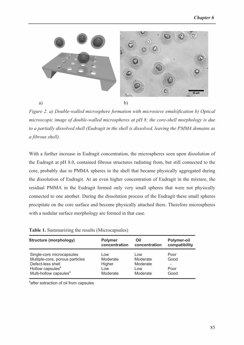
Chapter 6
a) b)
Figure 2. a) Double-walled microsphere formation with microsieve emulsification b) Optical
microscopic image of double-walled microspheres at pH 8; the core-shell morphology is due
to a partially dissolved shell (Eudragit in the shell is dissolved, leaving the PMMA domains as
a fibrous shell).
With a further increase in Eudragit concentration, the microspheres seen upon dissolution of
the Eudragit at pH 8.0, contained fibrous structures radiating from, but still connected to the
core, probably due to PMMA spheres in the shell that became physically aggregated during
the dissolution of Eudragit. At an even higher concentration of Eudragit in the mixture, the
residual PMMA in the Eudragit formed only very small spheres that were not physically
connected to one another. During the dissolution process of the Eudragit these small spheres
precipitate on the core surface and become physically attached there. Therefore microspheres
with a nodular surface morphology are formed in that case.
Table 1. Summarizing the results (Microcapsules)
Structure (morphology) Polymer concentration
Oil concentration
Polymer-oil compatibility
Single-core microcapsules Multiple-core, porous particles Defect-less shell Hollow capsulesa
Multi-hollow capsulesa
LowModerate Higher LowModerate
LowModerate Moderate LowModerate
PoorGood - PoorGood
aafter extraction of oil from capsules
85

Discussion and outlook
Table 2. Summarizing the results (Microspheres after extraction of Eudragit)
Structure (morphology) PMMAconcentration
Eudragitconcentration
Crumpled microspheres Swollen microspheres with corona Nanorough covered microspheres
Moderate Moderate Low
Moderate Higher Even higher
Outlook of research and possible industrial applications
Microsieve emulsification
Although microsieve emulsification lends itself in principle to large scale production, the
industrial application of this process is restricted to high added value products due to the
relatively high costs necessary for a high production volume. The transmembrane flux
reported in this thesis (> 90x10-6 m3/m2s for ~ 25 μm droplets) is an interesting step forward to
make the process commercially attractive. For the production of 1 ton encapsulates per hour
with the systems discussed in this thesis (using 3 wt% polymer, and 3% oil), one would need
to emulsify roughly 17 tons of solution per hour. With the fluxes found here, this would
require roughly 40 m2 microsieve surface area (assuming a density of 1330 kg/m3 of the
solution), which is well within practical range.
0
0.05
0.1
0.15
0.2
0.25
0.3
100 1000 10000Radius (nm)
Norm
alize
d W
eigh
t*Ga
mm
a (-)
R = 2033 nm
Figure 3. Sunflower oil-water emulsion with an average size of 4 µm prepared using a 0.8 µm
high porosity Aquamarijn microsieve a) DLS graph of the emulsion b) optical microscope
image. Conditions: 4% Span 80 in oil and 1% SDS in water; operating pressure was 124
mbar.
86

Chapter 6
In food applications the size of capsules typically has to be smaller than 20 μm, otherwise it
will influence the sensory properties of the product. For injectable drug delivery systems a
microsphere size of around 10 μm is desired [2]. The size of the emulsion droplets can be
reduced by using a smaller pore size of the microsieve. With microsieves having a pore size
of 0.8 μm, a droplet size of 4 μm is produced (figure 3). This preliminary experiment
demonstrates the feasibility of preparing small droplets with this technique.
A major problem associated with long term processing using microsieve emulsification is
fouling. Surface modification of these sieves with organically coated monolayers or polymeric
brushes could help to prevent this problem. However, it is difficult to design a single coating
that can repel all components during emulsification. Recent work has shown that zwitterionic
polymer-based coatings can significantly repel protein adsorption to the surface [20]. The
repulsion efficiency varies with the type of protein. Therefore, such a modification may not
always guarantee stable emulsification performance in the presence of different polymers and
oil mixtures. On the other hand, organic or polymer coatings could give ample opportunities
for optimization of the surface properties.
Microcapsules
Although microcapsule preparation is considered a well-established field, for each application
new combinations of new materials and processes are required. The design of microcapsules
starts first by considering the application for which the capsules are aimed. Specific material
properties need to be identified and then this can be translated into suitable processes.
Therefore, by identifying the right materials and processes a functional encapsulate can be
prepared. Preparing the capsules by a phase separation process is a simple and robust method,
that can be used for a wide range of polymers.
Different oil-soluble or oil-dispersible ingredients can for example be encapsulated in
Eudragit capsules using the phase separation process. These porous microcapsules are
especially interesting materials for cell immobilization [21], since the porous matrix will
allow essential micronutrients to diffuse into the capsules. However, the DCM used in the
present studies for the preparation of the capsules is probably not very compatible with the
cells. Therefore, it may need to be replaced with other less toxic solvents. However, this will
also affect the phase separation process which is dependent on the solvent removal rate.
Furthermore, this general phase separation process may in principle also be carried out with
other more biocompatible polymers like polycaprolactone, polylactide, ethyl cellulose or
87

Discussion and outlook
hydroxypropyl methylcellulose. It is clear that determining the optimal conditions for the
preparation of microcapsules with other polymers and solvents requires additional research.
Hollow microcapsules
The hollow capsules presented in this thesis could be an adequate product for loading active
ingredients. Hollow capsules prepared with different types of internal structures can also act
as microreactors [12]. The hollow capsules may be used to load them with specific enzymes.
On demand release of these enzymes will then initiate enzymatic reactions. A possible
application may be in microbially-enhanced oil recovery [22], in which microbes are loaded
in microparticles and subsequently released in the medium for recovering oil from a crude
mixture.
Additionally, hollow capsules are used for ultrasound-mediated drug delivery systems [23] in
which the drug-loaded particles are exposed to an acoustic medium to release the active
component. For this application, the capsules need to be smaller and more uniform than the
present capsules; this may be achieved by using smaller pore size membranes as mentioned in
the emulsification section. With the same process, hollow capsules may be obtained with
other biocompatible polymers such as polycaprolactone, polylactide, ethyl cellulose, or
hydroxypropyl methylcellulose.
Double-walled microspheres
Double-walled microspheres prepared by blending of two polymers results in microspheres
with different core-shell structures. Eudragit dissolves at alkaline pH to leave the encapsulated
microspheres with different surface structures, depending on the initial composition.
Microspheres from blends of two polymers may thus be used to obtain both pH-dependent
and pH-independent release of encapsulated ingredients. The PMMA core material used in the
present study may also be replaced with biodegradable polymers like polycaprolactone,
polylactide, ethyl cellulose or hydroxypropyl methylcellulose can potentially lead to useful
materials for oral delivery systems.
A major advantage of double-walled microspheres is that active ingredients can be located in
the core and both the core and shell can be engineered to achieve a tailored release profile.
Since some core material may be expected to remain in the shell during the phase separation
process, it will be released immediately upon dissolution of Eudragit and the remaining active
88

Chapter 6
ingredient, located in the core (e.g. consisting of polylactide) will be released during a longer
period by diffusion through the matrix.
Complex structures formed with phase separation are expected to strongly influence release
properties. Therefore, release studies with model drug compounds are very interesting for
future investigations. More delicate materials like probiotics can be initially entrapped in oil
shells and further coated with Eudragit for pH-triggered release. These encapsulated
probiotics may then be further protected from the low pH in the stomach by an oil barrier in
an Eudragit shell. When the capsules reach the colon, the Eudragit shell is expected to
dissolve while releasing the probiotics. This concept may also be applied in medicinal foods,
since addition of probiotics has been claimed to have several health benefits like prevention of
colon cancer [24]. The dual coating of oil and Eudragit may enhance the viability of
probiotics during their passage through the upper gastrointestinal (GI) tract. This general
concept can also be applied to food grade biopolymers with similar properties such as shellac,
ethyl cellulose or hydroxypropyl methylcellulose and other less toxic solvents such as ethyl
acetate or alcohols.
Proposal
Towards industrial scale production of microspheres and capsules
A serious hurdle towards upscaling the production of microcapsules is the use of dilute
solutions. Preparing 1 ton of microcapsules from a solution of 3 wt% Eudragit and 3 wt% oil
in DCM would require the use of about 17 tons of DCM, which all has to evaporate. The
aqueous phase normally is a number of times larger than the dispersed phase (e.g. 300 tons or
more). Since the evaporation times for DCM are in the range of several hours, one would need
very large reactor volumes. For 1 ton per hour production and 6 hours evaporation time, one
would need 330 tons / h x 6 = 1980 m3 reactor volume. This shows that there are still
important challenges for industrialization. An increase of the concentrations used will help to
dramatically reduce these numbers (Table 3). It is clear that this will have a major influence
on the phase separation process, which therefore needs to be further investigated and
optimized for lower volumes of DCM and continuous water phase.
89
Discussion and outlook
Table 3. Amount of DCM required to prepare 1 ton of capsules
Amount of Eudragit % (w/v)
Amount of oil % (w/v)
Amount of DCM required ton
3 5 7 10
3 5 7 10
17 10 7 5
New techniques using dead-end emulsification as e.g. developed by Nanomi
(www.nanomi.com) will also dramatically lower the required volume of the continuous
phase. A much higher concentration (e.g. a ratio of dispersed phase to continuous phase of up
to 10-20%) is well possible. A method developed by Hennink et al. [25] for the preparation of
solvent free microcapsules can also be an alternative. However, this can most probably only
be performed with aqueous phase separated polymers in water-water type of emulsion.
Nevertheless, it is clear that suitable combinations of materials and processes can be designed
for different applications.
90

Chapter 6
91
References
[1] A. J. Gijsbertsen-Abrahamse, A. Van Der Padt, R. M. Boom, J. Membr. Sci. 2004, 230, 149.
[2] G. Veldhuis, M. Gironés, D. Bingham, Drug Delivery Tech. 2009, 9, 24.
[3] N. A. Wagdare, A. T. M. Marcelis, R. M. Boom, C. J. M. van Rijn, J. Colloid and Interface
Sci. 2011, 355, 453.
[4] N. A. Wagdare, A. T. M. Marcelis, O. B. Ho, R. M. Boom, C. J. M. van Rijn, J. Membr. Sci.
2010, 347, 1.
[5] S. Van Der Graaf, C. G. P. H. Schro�n, R. G. M. Van Der Sman, R. M. Boom, J. Colloid and
Interface Sci. 2004, 277, 456.
[6] K. C. van Dijke, G. Veldhuis, K. Schro�n, R. M. Boom, AIChE J. 2010, 56, 833.
[7] H. Sawalha, K. Schro�n, R. Boom, AIChE J. 2009, 55, 2827.
[8] H. Sawalha, K. Schro�n, R. Boom, Polym. Eng. Sci. 2010, 50, 513.
[9] S. E. Bae, J. S. Son, K. Park, D. K. Han, J. Control. Release 2009, 133, 37.
[10] Y. Itoh, M. Matsusaki, T. Kida, M. Akashi, Biomacromolecules 2006, 7, 2715.
[11] N. Kato, T. Ishii, S. Koumoto, Langmuir 2010, 26, 14334.
[12] M. Delcea, A. Yashchenok, K. Videnova, O. Kreft, H. Möhwald, A. G. Skirtach, Macro.
Biosci. 2010, 10, 465.
[13] Q. Yuan, O. J. Cayre, S. Fujii, S. P. Armes, R. A. Williams, S. Biggs, Langmuir 2010, 26,
18408.
[14] D. Lensen, K. Van Breukelen, D. M. Vriezema, J. C. M. Van Hest, Macro. Biosci. 2010, 10,
475.
[15] F. J. Rossier-Miranda, K. Schro�n, R. Boom, Langmuir 2010, 26, 19106.
[16] G. C. Kini, S. L. Biswal, M. S. Wong, in Adv. Polym. Sci. 2010, 229, 89.
[17] D. X. Hao, F. L. Gong, G. H. Hu, J. D. Lei, G. H. Ma, Z. G. Su, Polymer 2009, 50, 3188.
[18] F. Lecomte, J. Siepmann, M. Walther, R. J. MacRae, R. Bodmeier, J. Control. Release 2003,
89, 457.
[19] C. Berkland, E. Pollauf, D. W. Pack, K. Kim, J. Control. Release 2004, 96, 101.
[20] L. Li, R. E. Marchant, A. Dubnisheva, S. Roy, W. H. Fissell, J. Biomater. Sci., Polym. Ed.
2011, 22, 91.
[21] X. Zhang, H. He, C. Yen, W. Ho, L. J. Lee, Biomaterials 2008, 29, 4253.
[22] A. H. Tullo, Chem. Eng. News 2009, 87.
[23] C. Chlon, C. Guédon, B. Verhaagen, W. T. Shi, C. S. Hall, J. Lub, M. R. Böhmer,
Biomacromolecules 2009, 10, 1025.
[24] L. R. Ferguson, M. Philpott, Curr. Cancer Drug Targ. 2007, 7, 459.
[25] O. Franssen, W. E. Hennink, Int. J. Pharm. 1998, 168, 1.


Summary
Encapsulation and use of capsules for controlled release has several applications in
pharmaceuticals, foods, cosmetics, detergents and many other products for consumers. It can
contribute to sustainability, since it allows an efficient use of active materials, delivery at the
required site and possibly a longer shelf life of the products. Many encapsulation systems are
basically very thin shells (10 nm – 10 µm) around microscopic reservoirs (100 nm – 100 µm),
in which active ingredients are trapped. The release properties are strongly dependent on the
material properties of the shell, but also on their size and uniformity.
The overall objective of this research is to understand the formation process of microcapsules
and microspheres by using phase separation in well-defined droplets of a polymeric solution.
The primary droplets were produced with microsieve emulsification; the polymer used was
Eudragit FS 30D (a commercial copolymer of poly (methyl acrylate-co-methyl methacrylate-
co-methacrylic acid) 7:3:1). These charged carboxylate groups make the polymer water-
soluble at higher pH (>7), allowing for release by a change in pH.
Chapter 2 presents results that give more insight into microsieve emulsification with high
porosity micro-engineered membranes. The droplet formation was strongly influenced by the
dynamics of surfactant adsorption. The presence of suitable surfactants in both phases
prevents the coalescence of droplets and wetting of microsieve membranes by the dispersed
phase during oil droplet formation. This resulted in the formation of stable emulsions of
droplets with a narrow size distribution. The flux of the dispersed phase could be increased an
order of magnitude compared to previous methods, without loss of size-distribution of the
droplets. Thus, use of a high-porosity membrane, in combination with suitable surfactants in
both the dispersed and continuous phases resulted to a much more effective and efficient
emulsification process.
In Chapter 3 crossflow microsieve emulsification was used to prepare porous microcapsules
with an average size of about 30 µm. A mixture of Eudragit and hexadecane in DCM was
emulsified in water. Being a poor solvent for this polymer, demixing of the droplet into a
polymeric shell and a hexadecane-rich core occurred upon extraction of the DCM into the
water phase. At a low ratio of concentrations of polymer and hexadecane, the shells were
found to be porous. Increasing this ratio resulted in a reduction of the porosity and pore size of
the shell. The Eudragit has a pH-dependent solubility. It is insoluble at acidic conditions and
rapidly dissolves at alkaline conditions. The capsules were found to be stable at a pH lower
93

Summary
than 7.0, whereas the oil core was released within half an hour at pH 7.1 and within a minute
at pH 8.0. The morphology of the microcapsules can be adapted with a careful choice of the
concentrations of polymer, hexadecane and solvent. At higher concentrations of polymer, the
tiny oil droplets that were captured in the forming Eudragit shell were unable to coalesce
completely and small, isolated pores were formed within the shell matrix. This could
influence the permeability properties of the shell.
The potential for new microcapsule morphologies was further explored in Chapter 4 where the
formation of Eudragit capsules with other oils instead of hexadecane was studied, and in
Chapter 5 where a blend of PMMA and Eudragit was used.
In Chapter 4 the effects of chain lengths of vegetable oils on the formation of porous
microcapsules with hollow and multi-compartment structures is discussed. The encapsulation
of oil and the morphology of the resulting microcapsules depend on the interaction between
the Eudragit polymer and the type of oil that was used. Microcapsule formation using long
chain length oils such as sunflower oil, olive oil and coconut oil resulted in well-defined
microcapsules with a single encapsulated oil droplet, covered with a Eudragit-rich shell. On
the other hand, capsules prepared with relatively short chain length oils, such as medium
chain triglyceride oil, resulted in capsules with many individual small oil droplets
encapsulated in an Eudragit matrix. This is thought to stem from different rates of phase
separation. Medium chain length oil (MCT oil, a low MW oil) is relatively well soluble. Thus,
the solvent may diffuse out for a significant time, without phase separation setting in. Only
when the polymer concentration has already become rather high, phase separation occurs and,
the MCT oil droplets get trapped in the Eudragit matrix. Long chain length oils are less
soluble, and phase separation between the oil and polymer will set in at an earlier stage,
before much solvent has diffused out, and the polymer concentration is still relatively low.
Thus the initial small oil droplets merge into one single core. Extraction of the oil from the
microcapsules with hexane results in the formation of hollow porous shells as was
investigated with optical microscopy and SEM. These structures are formed during
microcapsule formation due to the complex phase separation processes in the Eudragit-water-
oil-DCM quaternary system.
In Chapter 5 the formation of microcapsules is further explored by using a blend of
poly(methyl methacrylate) (PMMA) and Eudragit. Microspheres formed with this blend were
found to consist of a PMMA core inside an Eudragit-rich shell, which tends to be porous. As
the amount of Eudragit is increased, a thicker and more porous outer shell is formed due to the
94

Summary
95
enhanced interaction of water with Eudragit. After dissolution of the Eudragit at high pH,
different core surface structures resulted, from irregular surfaces to microspheres with a fiber-
like, swollen corona around it, and to a surface covered with small nodular structures,
dependent on the concentrations of PMMA and Eudragit in the initial mixture. As already
indicated above, these structures are formed as a result of complex phase separation processes
between polymers and (non)solvents, and between the two polymers.
In Chapter 6 the results described in this thesis were compared with existing literature,
yielding an outlook on the field of microencapsulation through phase separation. Microsieve
emulsification is feasible for the production of emulsions with a throughput from millilitres to
tons of volume. The microcapsules developed here can be used for encapsulation of oil-
soluble active ingredients and release by a pH trigger. The hollow capsules can possibly be
interesting materials as micro-reactors, e.g. by loading with enzyme and performing
enzymatic reactions on demand. The complex structures formed upon phase separation of two
polymers can be employed for obtaining complex release profiles. A general concept is
discussed on how to obtain various interesting complex structures with phase separation
combined with microsieve emulsification. Finally, a conceptual process design is discussed
for industrial scale production of microcapsules and microspheres with use of microsieve
emulsification.
This thesis has yielded insight in the formation of a range of microcapsule morphologies by
investigating a range of new production methods (microsieves and demixing conditions) and
formulations (different concentrations, oils and using one polymer or a blend), and through
this provides better insight into the mechanisms of microcapsule formation. While some of the
structures may be directly used for microcapsule formation, some other structures may well
have potential for other applications.


Samenvatting
Het opnemen van stoffen in en de toepassing van capsules voor gecontroleerde afgifte van de
ingesloten componenten vindt toepassing in diverse farmaceutische producten,
voedingsmiddelen, cosmetica en vele andere consumentenproducten. Het kan bijdragen aan
duurzaamheid, aangezien er efficiënt gebruikt gemaakt wordt van actieve componenten, er
afgifte op de gewenste locatie plaatsvindt en het kan leiden tot een langere houdbaarheid van
de producten. Vele microcapsules zijn in principe microscopische reservoirs (100 nm – 100
µm doorsnede), waarin actieve componenten opgesloten zitten, met daaromheen een dunne
schil (10 nm – 10 µm). De afgifte-eigenschappen zijn sterk afhankelijk van de
materiaaleigenschappen van de schil, maar ook van de grootte en de gelijkvormigheid.
De algemene doelstelling van dit onderzoek is om inzicht te krijgen in het vormingsproces
van microcapsules en microbolletjes door middel van fasescheiding in goed gedefinieerde
druppels van een polymeer oplossing. De primaire druppels worden geproduceerd met behulp
van membraanemulsificatie van een Eudragit FS 30D polymeerolossing (een commercieel
poly(methyl acrylaat-co-methyl methacrylaat-co-methacrylzuur) 7:3:1 copolymeer). De
geladen carboxylaat groepen maken het polymeer oplosbaar bij een pH >7, waardoor afgifte
door verandering van pH mogelijk is.
Hoofdstuk 2 beschrijft resultaten die meer inzicht geven in het emulsificatieproces van olie in
water met behulp van microzeefmembranen die zo ontworpen zijn dat ze een hoge porositeit
hebben. De aanwezigheid van geschikte surfactanten in beide fasen voorkomt het
samensmelten van druppels na vorming en tevens het hechten van de oliedruppels aan het
membraan tijdens de vorming. De druppelvorming wordt sterk beïnvloed door de dynamiek
van surfactantadsorptie. Het gebruik van geschikte surfactanten resulteerde in stabiele
emulsies van druppels met een smalle grootteverdeling. De flux van de gedispergeerde fase
was een grootteorde hoger in vergelijking met andere methoden, zonder dat dit invloed had op
de grootteverdeling van de druppels. Het gebruik van hoogporeuze membranen in combinatie
met geschikte surfactanten in beide fasen resulteert dus in een veel effectiever en efficiënter
emulsificatieproces.
In hoofdstuk 3 werd hetzelfde emulsificatieproces met microzeven gebruikt om poreuze
microcapsules te maken met een gemiddelde grootte van circa 30 µm. Een mengsel van
Eudragit en hexadecaan in dichloormethaan werd in water geëmulgeerd. Omdat hexadecaan
een slecht oplosmiddel is voor dit polymeer en omdat het dichloormethaan werd geëxtraheerd
97

Samenvatting
naar de waterfase vond er ontmenging in de druppels plaats waarbij een polymere schil rond
een hexadecaan-rijke kern ontstond. Bij een lage verhouding in concentraties van polymeer tot
hexadecaan bleken de polymeerschillen poreus te zijn. Verhogen van deze verhouding
resulteerde in een minder poreuze schil met kleinere poriegroottes. De oplosbaarheid van
Eudragit in water is pH-afhankelijk. Het is onoplosbaar in zuur maar lost snel op onder
basische omstandigheden. De capsules bleken stabiel te zijn bij een pH lager dan 7,0; bij een
pH van 7,1 kwam de oliekern in een half uur vrij en bij pH 8,0 zelfs binnen één minuut. Door
een zorgvuldige keuze van de concentraties polymeer, hexadecaan en oplosmiddel kan de
uiteindelijke morfologie van de microcapsules bepaald worden. Bij hogere concentraties aan
polymeer werden kleine oliedruppels gevangen in de vormende Eudragit schil en deze waren
daardoor niet meer in staat om volledig met elkaar te versmelten waardoor kleine poriën in de
polymeermatrix van de schil ontstonden. Dit kan de permeabiliteitseigenschappen van de schil
beïnvloeden. De mogelijkheid voor vorming van microcapsules met een andere morfologie
werd verder onderzocht in hoofdstuk 4, waarbij andere oliën in plaats van hexadecaan werden
gebruikt, en in hoofdstuk 5, waar een mengsel van PMMA en Eudragit werd gebruikt.
In hoofdstuk 4 worden de effecten van ketenlengte van plantaardige oliën op de vorming van
poreuze microcapsules besproken. De encapsulatie van olie en de morfologie van de ontstane
microcapsules zijn afhankelijk van de interactie tussen het Eudragit polymeer en het gebruikte
type olie. Emulsificatie met oliën met lange vetzuurketens, zoals zonnebloemolie, olijfolie en
kokosolie, resulteerde in goed gedefinieerde microcapsules waarin een enkele druppel olie de
kern vormde, omringd door een Eudragit-rijke schil. Anderzijds, indien oliën werden gebruikt
met relatief korte vetzuurketens, resulteerde dit in capsules met veel kleine individuele
oliedruppeltjes verspreid in een Eudragit matrix. Dit is waarschijnlijk het gevolg van
verschillende snelheden waarmee de fasescheiding plaatsvindt. Een dergelijke olie met een
laag moleculair gewicht (MCT olie) is relatief goed oplosbaar. Hierdoor kan het oplosmiddel
er langer uit diffunderen voordat er fasescheiding plaatsvindt. Pas als de polymeerconcentratie
erg hoog is geworden treed er fasescheiding op en worden de MCT oliedruppeltjes opgesloten
in de Eudragit matrix. Oliën met lange vetzuurketens zijn minder goed oplosbaar waardoor
fasescheiding tussen de olie en het polymeer in een eerder stadium plaatsvindt, voordat veel
oplosmiddel naar buiten is gediffundeerd en de concentratie van het polymeer nog relatief
laag is. Hierdoor kunnen de initieel gevormde kleine oliedruppeltjes nog samensmelten tot
één enkele kern. Extractie van de olie uit de microcapsules met behulp van hexaan resulteerde
in holle poreuze capsules zoals optische microscopie en SEM-opnamen lieten zien. Deze
98

Samenvatting
99
structuren zijn ontstaan tijdens de vorming van de microcapsule door de complexe
fasescheidingsprocessen in het Eudragit-water-olie-dichloormethaan systeem.
In hoofdstuk 5 is de vorming van microcapsules verder onderzocht voor mengsels van
poly(methyl methacrylaat; PMMA) en Eudragit. De microdruppels die gevormd werden met
dit mengsel bleken een kern te hebben van PMMA, waaromheen een poreuze Eudragit-rijke
schil zat. Wanneer er meer Eudragit wordt gebruikt, wordt er een dikkere en meer poreuze
Eudragit schil gevormd door een sterkere interactie met water. Nadat Eudragit is opgelost bij
hoge pH ontstaan er verschillende oppervlaktestructuren van de overgebleven kern. Dit
varieert van onregelmatige oppervlakken tot microdruppels omgeven door een fiber-achtige
gezwollen corona, tot een oppervlak bedekt met kleine knobbelachtige structuren, afhankelijk
van de concentraties van PMMA en Eudragit in het oorspronkelijke mengsel. Zoals hierboven
reeds beschreven is worden deze structuren gevormd als gevolg van de complexe
fasescheidingsprocessen tussen de twee polymeren en de twee oplosmiddelen.
In Hoofdstuk 6 worden de resultaten uit dit proefschrift vergeleken met bestaande literatuur,
waardoor een betere visie op het gebied van micro-encapsulatie met behulp van fasescheiding
wordt verkregen. Met behulp van microzeefemulsificatie zijn productievolumes van milliliters
tot tonnen emulsies haalbaar. De microcapsules die hier ontwikkeld zijn kunnen worden
gebruikt om olie-oplosbare actieve bestanddelen te encapsuleren, welke kunnen vrijkomen
door een pH-schakelaar. De holle capsules kunnen mogelijk interessant zijn als micro-reactor,
bijvoorbeeld door er een enzym in te plaatsen en op afroep enzymatische reacties te laten
plaatsvinden. De complexe structuren, welke gevormd werden na fasescheiding van twee
polymeren, kunnen gebruikt worden om complexe afgifteprofielen te verkrijgen. Er is een
algemeen concept beschreven hoe verschillende interessante complexe structuren kunnen
worden verkregen met behulp van fasescheiding in combinatie met microzeefemulsificatie.
Ten slotte wordt een concept voor een procesontwerp besproken voor productie van
microcapsules en microbolletjes op industriële schaal met behulp van microzeefemulsificatie.
Dit proefschrift heeft inzicht gegeven in de vorming van microcapsules met verschillende
morfologieën door een reeks van nieuwe productiemethoden (microzeven en
fasescheidingscondities) en formuleringen (verschillende concentraties, oliën en het gebruik
van één polymeer of een polymeermengsel) te onderzoeken en geeft daarmee een beter inzicht
in de mechanismen van microcapsulevorming. Sommige van de onderzochte structuren
kunnen direct toegepast worden voor de vorming van microcapsules, terwijl sommige andere
verkregen structuren veelbelovend zijn voor andere toepassingen.


Appendix
a) b) c) d)
Chapter 1, figure 1, page 3
a) b) c)
Chapter 3, figure 3, page 40
Microsieve emulsification process
pH 8.0
PMMA microspherePMMA/ED microsphere
Chapter 5, figure 1, page 65
101

Acknowledgments
Going for higher education was a dream from childhood. The dream came true when I got an
opportunity to do my PhD at Wageningen UR, The Netherlands. Looking back in to last four
years, my stay at Wageningen was very memorable! Indeed it turned out in to a great
opportunity in life to explore the PhD program at Wageningen. I have received plenty of
helpful hands to travel this journey and to reach this destination, therefore would like to
gratitude with many thanks to those kind people.
My first thanks goes to my promoter Prof. Dr. Cees van Rijn for giving me an opportunity to
work on this PhD project at Wageningen. Dear Cees, I remember when I sent an application
for this position, you responded very quickly. You have given me lot of freedom to work in
this project, at the same time you motivated and encouraged me. Your smart ideas made me
more interesting to work. Besides to science, I have also learned many valuable professional
aspects from you. It was my great pleasure to work with you, a very special professor. Also I
am grateful for giving me an opportunity to work for Aquamarijn.
I would like to extend my gratitude to my second promoter Prof. Dr. Remko Boom. Dear
Remko, You had great ideas to bring into my project. I had very fruitful discussions with you.
Indeed you have made very valuable contribution to my work with your expertise. Your
enthusiasm and significant interest in my topic created additional value to the work. I have
learnt a lot about this topic from you. Totally it was great honour for me to work with you.
It is my immense pleasure to thank my daily advisor and co-promoter Dr. Ton Marcelis for
his kindness and support. Ton you have given me freedom to work on my own but whenever I
was in trouble you were there to support me. You helped me to improve my scientific writing
skills. You are a best advisor one can get for doctoral studies with having lot of patience and
trust. I am extremely thankful for your generous input and very kind supervision.
I would like to thank Ganesan for his help in the initial stage of project. Also, thanks to Jacob
for his helping hands, especially in AFM measurements on microspheres. I am grateful to
Aquamarijn BV for providing microsieves to perform interesting emulsification experiments.
The team of Nanomi BV is thanked for their valuable advices on use of emulsification set-up.
103

Acknowledgments
I would like to thank all colleagues of work package 2B of MicroNed program for sharing
ideas and mutual interactions, especially the groups of Food Physics and Food Process
Engineering. I also thank Prof. Dr. Martien Cohen Stuart, Prof. Dr. Wim Hennink, Prof. Dr.
Jan Meuldijk and Dr. Gert Veldhius for taking part in my promotion commission.
I am grateful to many people from the group of Physical Chemistry and Colloid Science (very
pleasant neighbours) for all the help with measurements and valuable discussions. I would
like to thank Adriaan and Tiny from WEMC for their help in SEM measurements. I appreciate
the help of Marcel in AFM, SEM and many other machines. Also thanks to Barend for
friendly discussions.
Working at Organic Chemistry was nice with the colleagues of different nationalities and had
a good ambience of an international environment. I would like to thank my colleagues Ai,
Willem, Jacob, Jacinthe, Alexandre and Florine for social interactions during lunch breaks.
Being a nice officemates and kind members of microfluidics lab at ORC was enjoyable. I
would like to thank Elly and Aleida for taking care of all bureaucratic paper work. Jerome
thanks for discussions in project work and for the Dutch summary. I also thank Sidhu, Umesh,
Nagendra, Satesh, Sourav, Nishant, Murali, Feng, Tin, Jaime, Luc, Jurjen, Ruud, Michel,
Radostina, Kim, Loes, Bart, Wouter, Yao, Anke, TuHa, and Peter for all the help during last
four years. And also thanks to all staff members and all technicians of ORC for their timely
help. I had some nice interaction with colleagues from Food Process Engineering group,
especially during PhD trip to USA and annual FPE symposium. Especially, I would like to
thank Jimmy and Nanik, Thomas, Francisco, Tim, Jos, Joyce and Karin for helpful
discussions.
I am grateful to my Master thesis supervisor Prof. Dr. S. V. Lonikar for guiding me in right
direction after my M.Sc. Also my sincere thanks to Dr. P. G. Shukla, Dr. P. P. Wadgaonkar,
Dr. A. N. Bote, Dr. A. S. Jadhav and S. B. Katte from NCL, Pune, for their help and
encouragement.
Working at abroad means missing home and friends, but soon after arrival I found the group
of wonderful friends. Kishore, Arun, Feana, and Byjesh, thanks for the time we spend on
cooking, eating and followed by nice discussions together. In the presence of you guys my
104

Acknowledgments
105
first two years went very quickly. I also thank to my nice cricket team from last two years at
Organic Chemistry namely Sidhu, Umesh, Nagendra, Satesh, Sourav, Sourabh and Ankush.
Thanks for working together and also for making parties together. I thank my friends,
Mahadev, Gajanan, Shivkumar, Jijeesh, Vishwanath and Sanjay. It was pleasure and fun
during our visits and trips together. Thanks to Yogesh, Sudhir and Sachin for friendship,
social interactions and helpful discussions, it was nice travelling together for some occasions
within Netherlands and Germany. I received valuable information from Nilesh Kukalyekar
and Yogesh, before I was able to reach Netherlands. I also thank Anitha, Senthil, Abhishek,
Ganesan, Nitya, Hema, Esha, Animesh, Sameer, Vani, Pradnya, Manoj, Madhuri, Surender,
Liyakat, Soumi, Supriya and many more for having get-togethers and social interactions.
I would like to thank my paranymphs Kishore and Willem for to be an important part on this
occasion. I also thank to Sidhu for cover page design.
It is my most pleasure to thank all my family members for their love, support and
encouragement. It is my father, who is continuously encouraging me from the childhood to
do something valuable in life. Appa, you have made lot of efforts for me. Your patience,
enthusiasm and trust made me possible to do something special. My mother, for her infinite
love and care from the childhood. Awwa, your love and motivation was the reason for me to
being good and to do well. I hope you both are proud of me for being your son. I am also
thankful to my brother, sisters, uncle, aunts and cousins for their valuable support and
encouragement. I hope you are all happy with this achievement of mine!
Finally, I sincerely thank to all those people, who have helped me directly or in directly in last
four years. I am looking forward to keep in touch in future.
Nagesh


Curriculum vitae Nagesh A. Wagdare was born on 19 June, 1983 in
Gholsgaon, a small village near Akkalkot in
Maharashtra, India. He went to high school (1998-
2000) at Maharashtra State Technical College,
Solapur. Subsequently, he studied for BSc in
Chemistry (2000-2003) at Shivaji University.
th
On completion of his bachelor studies, he continued to pursue his MSc in Polymer Chemistry
(2003-2005) at Shivaji University. As part of his MSc studies, he worked on the thesis project:
“Synthesis of aliphatic polyesters for controlled release”, under supervision of Prof. S. V.
Lonikar at the Department of Chemistry, Solapur. From September 2005 to May 2007, he
worked on an industrial project: “Microcapsules for fabric care”, in the group of Dr.
Parashuram G. Shukla, Polymer Science and Engineering Division, National Chemical
Laboratory, Pune.
From June 2007 to May 2011, he worked on the PhD project: “Structuring Microspheres”, at
Wageningen University, The Netherlands. He was supervised by Dr. Antonius Marcelis and
Prof. Cees van Rijn from the Laboratory of Organic Chemistry, and Prof. Remko Boom of the
Food Process Engineering Group. Most of the research performed in the last four years is
described in this thesis. From June 2011, Nagesh is working as a Scientist for Aquamarijn
Micro Filtration BV, The Netherlands.
Email: [email protected]
107


Publication list
Peer Reviewed Journals
Nagesh A. Wagdare, Antonius T.M. Marcelis, O. Boen Ho, Remko M. Boom and Cees J.M.
van Rijn, High throughput vegetable oil-in-water emulsification with a high porosity micro-
engineered membrane, Journal of Membrane Science, 2010, 347, 1-7
Nagesh A. Wagdare, Antonius T.M. Marcelis, Remko M. Boom and Cees J.M. van Rijn,
Porous microcapsule formation with microsieve emulsification, Journal of Colloid and
Interface Science, 2011, 355, 453-457
Nagesh A. Wagdare, Antonius T.M. Marcelis, Remko M. Boom and Cees J.M. van Rijn,
Microcapsules with a pH responsive polymer: influence of the encapsulated oil on capsule
morphology, Colloids and surfaces B: Biointerfaces, 2011, Article in press.
Nagesh A. Wagdare, Jacob Baggerman, Antonius T.M. Marcelis, Remko M. Boom and Cees
J.M. van Rijn, Polymer microspheres with structured surfaces, Submitted for publication.
Conference Proceedings
Nagesh A. Wagdare, Antonius T.M. Marcelis and Cees J.M. van Rijn, Sunflower oil as a shell
material for oral delivery of food micronutrients, International Conference on
Bioencapsulation, Dublin, Ireland, 2008
Nagesh A. Wagdare, Antonius T.M. Marcelis and Cees J.M. van Rijn, Fabrication of edible
oil-water emulsions and double emulsions with high porosity microsieves, International
Conference on Food Rheology and Structure, Zürich, Switzerland, 2009
Nagesh A. Wagdare, Antonius T.M. Marcelis, Remko M. Boom and Cees J.M. van Rijn,
Phase separation-induced pH-sensitive microcapsule formation, World Congress on
Emulsions, Lyon, France, 2010
109

Training Activities
Overview of completed training activities Discipline specific activities
Courses
Polysaccharides as Food Colloids, Wageningen, 2007
Advanced Organic Chemistry, Wageningen, 2009-2011
Early stage researcher training in bioencapsulation, Anzre, Switzerland, 2009
Conferences
*International conference on bioencapsulation, Dublin, Ireland 2008
*International conference on food rheology and structure, Zürich, Switzerland, 2009
Annual NWO conference (Organic Chemistry), Lunteren, 2007 and 2008
Mini-symposium on membrane emulsification, Wageningen, 2009
Mini-symposium on dynamics of soft matter, Wageningen, 2009
World emulsion congress, Lyon, France, 2010
Annual NPS conference, Veldhoven, Netherlands, 2010
Nanoned/Microned symposium, Netherlands, 2007-2010
Food Process Engineering annual meeting, 2009 and 2010
Dutch Polymer Days, Veldhoven, Netherlands, 2010
* Represents oral presentations. At the other Conferences posters were presented
General courses
VLAG Ph.D. week, 2008
Techniques for scientific writing and presenting papers, 2010, Wageningen
Optionals
Preparation Ph.D. research proposal
Group meetings Laboratory of Organic Chemistry, 2007-2009,
Ph.D. study trip, Laboratory of Organic Chemistry, China, 2009
Ph.D. study trip, Food Process Engineering Group, USA, 2010
Literature study, Laboratory of Organic Chemistry, 2007-2008
111

The research carried out in this thesis was financially supported by the Dutch MicroNed
program.
Thesis layout: By the Author
Cover page design: Sidharam Pujari and Author
Printing: GVO drukkers & vormgevers B.V. / Ponsen & Looijen, Ede, NL