Embed Size (px)
Citation preview

GEOTECHNICAL I LABORATORY I EARTHWORKS I QUARRY I CONSTRUCTION MATERIAL TESTING
Proposed Subdivision – The Bower Stage 2 Site Classification
Boundary Road, Medowie
NEW15P-0033A-AA 18 September 2017

Qualtest Laboratory (NSW) Pty Ltd ABN: 98 153 268 89 8 Ironbark Close Warabrook NSW 2304 T: (02) 4968 4468 F: (02)4960 9775 W: www.qualtest.com.au NEW15P-0033A-AA
18 September 2017
McCloy Development Management
Suite 1, Level 3, 426 King Street
NEWCASTLE WEST NSW 2302
Attention: Mr Sam Rowe
Dear Sam
RE: Proposed Subdivision – The Bower Stage 2 (lots 201 to 230)
Boundary Road, Medowie
Site Classification
Please find enclosed our geotechnical report for Stage 2 of the proposed residential
subdivision ‘The Bower’ to be located off Boundary Road, Medowie.
The report includes recommendations for Site Classification in accordance with AS2870-2011,
“Residential Slabs and Footings”, and excavation conditions.
If you have any questions regarding this report, please do not hesitate to contact Shannon
Kelly or the undersigned.
For and on behalf of Qualtest Laboratory (NSW) Pty Ltd
Jason Lee
Principal Geotechnical Engineer

PROPOSED SUBDIVISION STAGE 2 – BOUNDARY ROAD, MEDOWIE
18 September 2017 i NEW15P-0033A-AA
Table of Contents:
1.0 Introduction .................................................................................................................. 1
2.0 Desktop Study .............................................................................................................. 1
3.0 Field Work ...................................................................................................................... 1
4.0 Site Description ............................................................................................................ 2
4.1 Site Regrade Works ......................................................................................................2
4.2 Surface Conditions ......................................................................................................2
4.3 Subsurface Conditions ................................................................................................4
5.0 Laboratory Testing ...................................................................................................... 8
6.0 Discussion and Recommendations........................................................................ 9
6.1 Site Classification to AS2870-2011 ............................................................................9
6.2 Excavation Conditions ............................................................................................. 10
7.0 Limitations .................................................................................................................... 11
Attachments:
Figure AA1: Site Plan & Approximate Test Pit Locations
Appendix A: Results of Field Investigations
Appendix B: Results of Laboratory Testing
Appendix C: CSIRO Sheet BTF 18

PROPOSED SUBDIVISION – THE BOWER STAGE 2 – BOUNDARY ROAD, MEDOWIE
18 September 2017 1 NEW15P-0033A-AA
1.0 Introduction
Qualtest Laboratory NSW Pty Ltd (Qualtest) is pleased to present this geotechnical assessment
report on behalf of McCloy Development Management (McCloy), for the proposed residential
subdivision of The Bower, Stage 2, located off Boundary Road, Medowie.
Based on the brief and Sales Plan provided, Stage 2 is understood to comprise of 30 residential
allotments (Lots 201 to 230).
The scope of work for the geotechnical investigation included providing discussion and
recommendations on the following:
Site classification to AS2870-2011, “Residential Slabs and Footings” for proposed subdivision
Lots 201 to 230;
Recommendations for excavation conditions for the Stage 2 site;
This report presents the results of the field work investigations and laboratory testing, and
provides recommendations for the scope outlined above.
2.0 Desktop Study
The scope of work has included a review of the following reports completed by Qualtest.
Geotechnical Assessment report, ‘Proposed Subdivision, Stages 1, 2 & 3, Boundary Road,
Medowie, (Report Reference: NEW15P-0033-AC, dated 25 August 2016).
Site Classification report, ‘Proposed Subdivision, The Bower Stage 1, Boundary Road,
Medowie’, (Report Reference: NEW15P-0033-AE, dated 31 May 2017).
Level 1 Site Regrade Assessment report, ‘Proposed Subdivision, The Bower Stage 2,
Boundary Road, Medowie, (Report Reference: NEW17P-0089-AA, dated 10 August 2017).
This report includes selected results from the previous reports referenced above, to supplement
information collected during the current investigations where applicable.
3.0 Field Work
The field work investigations were carried out on 22 and 23 August 2017 and comprised of:
DBYD search was undertaken to check proposed test locations for the presence of
underground services;
Site walkover to make observations of surface features at the property and in the
immediate surrounding area;
Excavation of 16 test pits (TP201 to TP216) using a 5 tonne rubber tracked excavator
equipped with a 450mm wide bucket to depths of up to 2.30m or prior refusal on
weathered rock;
Undisturbed samples (U50 tubes) and small bag samples were taken for subsequent
laboratory testing;
Test pits were backfilled with the excavation spoil and compacted using the excavator
bucket and tracks.

PROPOSED SUBDIVISION – THE BOWER STAGE 2 – BOUNDARY ROAD, MEDOWIE
18 September 2017 2 NEW15P-0033A-AA
Investigations were carried out by an experienced Geotechnical Engineer from Qualtest who
located the test pits, carried out the testing and sampling, produced field logs of the test pits,
and made observations of the site surface conditions.
Engineering logs of the test pits are presented in Appendix A.
Approximate test pit locations are shown on the attached Figure AA1. Test pits were located in
the field by handheld GPS and relative to existing site features including topographic features,
lot boundaries, existing developments and trees.
4.0 Site Description
4.1 Site Regrade Works
Site re-grading works were conducted on Lots 218 to 230, between the dates of 8 July 2017
and 7 August 2017.
Prior to filling, re-grade areas were stripped of all topsoil and unsuitable material to expose
suitable natural residual foundation profile. Re-grade works then consisted of filling with
approved site fill to finish design levels.
Filling was performed using site material won from excavations cut from around the site. The fill
material could generally be described as mixtures of Sandy CLAY, of medium to high plasticity,
fine to coarse grained sand, and with some fine to coarse grained gravel inclusions.
The approximate depth of fill placed ranged in the order of about 0.2m to 0.9m for the lots. The
fill was compacted in maximum lifts of 0.3m thickness. Any unsuitable or deleterious material
within the fill was removed by hand or mechanical means prior to final compaction of layers.
As the geotechnical testing authority engaged for the project, we state that the filling
performed for the regrade areas within Stage 2 (Lots 218 to 230), was carried out to Level 1
criteria as defined in Clause 8.2 – Section 8, of AS3798-2007, ‘Guidelines on Earthworks for
Commercial and Residential Developments’.
4.2 Surface Conditions
The site of Stage 2 is located off Boundary Road, Medowie, as shown in Figure AA1. The site is
located about 2km east of Grahamstown Lake, and about 100m east of Medowie Road on
the northern side of Boundary Road. The site is bounded by Boundary Road to the south and
by proposed future stages of the subdivision to the north, east and west. The area of the
proposed future stages generally comprises mostly cleared disused farmland and bushland,
with low density residential development fronting Boundary Road.
The site is situated in an area of gently undulating topography, on the mid slopes of a local hill
formation with low relief. Natural surface slopes are typically in the order of about 1° to 2°
towards the northeast.
At the time of the site investigation, trafficability by way of 4WD vehicle was good.
Based on observations on the days of the investigation which was carried out during fine
weather, the site was judged to typically be moderately to well drained primarily by way of
surface runoff towards the northeast.
Photographs of the site taken on the day of the site investigations are shown below.

PROPOSED SUBDIVISION – THE BOWER STAGE 2 – BOUNDARY ROAD, MEDOWIE
18 September 2017 3 NEW15P-0033A-AA
Photograph 1: Facing northwest from near
TP202 (Lot 203/204 boundary). Existing house
on Lot 203 shown on right of photo.
Photograph 2: Facing northeast from near
TP202 (Lot 203/204 boundary). Water tank
located at rear of existing house on Lot 203
visible on left of photo.
Photograph 3: Facing northwest from near
TP204 (Lot 206/207 boundary).
Photograph 4: Facing north from near TP204
(Lot 206/207 boundary).
Photograph 5: Facing southeast from near
TP209, Royal Avenue visible in top left corner.
Photograph 6: Facing south to southeast from
near TP210, Royal Avenue visible in
background.
Boundary Road

PROPOSED SUBDIVISION – THE BOWER STAGE 2 – BOUNDARY ROAD, MEDOWIE
18 September 2017 4 NEW15P-0033A-AA
4.3 Subsurface Conditions
Reference to the 1:100,000 Newcastle Coalfield Regional Geology Sheet indicates the site to
be underlain by the Permian Aged Tomago Coal Measures, which are characterised by
Siltstone, Sandstone, Coal, Tuff and Claystone rock types.
Table 1 presents a summary of the typical soil types encountered at test pit locations during the
field investigation, divided into representative geotechnical units.
Table 2 contains a summary of the distribution of the above geotechnical units at the test pit
locations.
TABLE 1 – SUMMARY OF GEOTECHNICAL UNITS AND SOIL TYPES
Unit Soil Type Description
1A FILL - TOPSOIL
Sandy CLAY – low plasticity, dark grey-brown, fine to medium
grained sand, root affected.
Silty SAND – fine grained, dark grey-brown, root affected.
1B CONTROLLED FILL
CLAY / Gravelly CLAY – medium to high plasticity, pale grey
with some orange-brown to red-brown, with some fine to
medium grained sand.
2 TOPSOIL
Sandy CLAY, Clayey Silty SAND, Silty CLAY and Sandy CLAY /
Silty Clayey SAND - low to medium plasticity, dark brown to
grey, fine to medium grained sand, root affected.
3 COLLUVIUM
Sandy CLAY – medium plasticity, dark grey-brown, fine grained
sand, with some fine grained sub-rounded gravel. Typically of
very stiff consistency.
4 RESIDUAL SOIL
CLAY – medium plasticity to high plasticity, varying colours
including brown and grey, orange-brown to red-brown, grey to
pale brown, trace to some fine to medium grained sand.
Typically of very stiff consistency, stiff in places.
5
EXTREMELY
WEATHERED (XW)
ROCK
(with soil
properties)
Extremely weathered Sandy SILTSTONE with soil properties,
excavated as Clayey GRAVEL - fine to medium grained,
angular to sub-angular, pale grey and pale orange / pale
brown to orange.
6
HIGHLY
WEATHERED (HW)
ROCK
Sandy SILTSTONE – pale grey to grey, sand mostly fine grained,
estimated strength ranging from very low to low. Generally
fractured or semi-fractured.

PROPOSED SUBDIVISION – THE BOWER STAGE 2 – BOUNDARY ROAD, MEDOWIE
18 September 2017 6 NEW15P-0033A-AA
TABLE 2 – SUMMARY OF GEOTECHNICAL UNITS ENCOUNTERED AT EACH TEST PIT LOCATION
Location Unit 1A
Fill: Topsoil
Unit 1B
Controlled Fill
Unit 2
Topsoil
Unit 3
Colluvium
Unit 4
Residual Soil
Unit 5
Extremely
Weathered Rock
Unit 6
Highly
Weathered Rock
Depth (m)
Current Geotechnical Assessment - Stage 2
TP201 - - 0.00 – 0.14 0.14 – 0.80 - 0.80 – 2.10
TP202 - 0.00 – 0.16 0.16 – 0.30 0.30 – 2.10 - -
TP203 - 0.00 – 0.10 - 0.10 – 0.40 - 0.40 – 0.45*
TP204 - 0.00 – 0.15 - 0.15 – 0.50 - 0.50 – 2.30
TP205 - 0.00 – 0.07 - 0.07 – 0.90 - 0.90 – 2.00
TP206 - 0.00 – 0.05 - 0.05 – 0.50 - 0.50 – 2.10
TP207 - 0.00 – 0.15 - 0.15 – 0.80 - 0.80 – 1.10*
TP208 - 0.00 – 0.20 0.20 – 0.38 0.38 – 0.90 - 0.90 – 1.00*
TP209 - 0.00 – 0.12 - 0.12 – 2.10 - -
TP210 0.00 – 0.15 0.15 – 0.50 - - 0.50 – 2.10 - -
TP211 0.00 – 0.18 0.18 – 0.65 - - 0.65 – 1.70 - 1.70 – 2.20^
TP212 0.00 – 0.12 0.12 – 0.65 - - 0.65 – 1.60 - 1.60 – 2.00^
TP213 0.00 – 0.24 0.24 – 0.80 - - 0.80 – 1.70 - 1.70 – 2.00^
TP214 0.00 – 0.18 0.18 – 0.45 - - 0.45 – 1.10 - 1.10 – 2.20^
TP215 0.00 – 0.12 0.12 – 0.40 - - 0.40 – 0.90 0.90 – 2.00^ -
TP216 0.00 – 0.09 0.09 – 0.50 - - 0.50 – 1.10 - 1.10 – 2.00^

PROPOSED SUBDIVISION – THE BOWER STAGE 2 – BOUNDARY ROAD, MEDOWIE
18 September 2017 7 NEW15P-0033A-AA
Location Unit 1A
Fill: Topsoil
Unit 1B
Controlled Fill
Unit 2
Topsoil
Unit 3
Colluvium
Unit 4
Residual Soil
Unit 5
Extremely
Weathered Rock
Unit 6
Highly
Weathered Rock
Previous Geotechnical Assessment (Ref: NEW15P-0033-AE, May 2017)
TP106 - - 0.00 - 0.25 - 0.25 - 2.00 - -
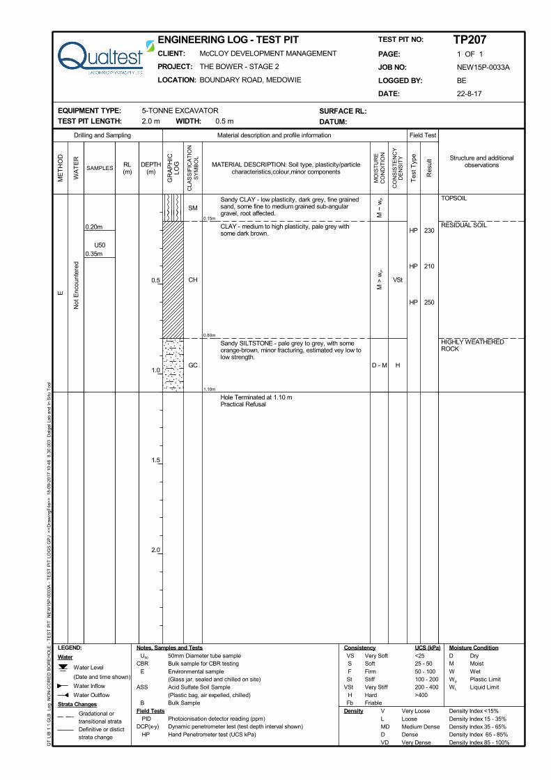
TP112 - - 0.00 - 0.09 - 0.09 - 1.00 1.00 - 1.30 1.30 - 1.60^
Previous Geotechnical Assessment (Ref: NEW15P-0033-AC.Rev1, August 2016)
TP-Q39 - - 0.00 - 0.20 - 0.20 - 1.50 1.50 - 1.80 -
TP-Q40 - - 0.00 - 0.20 - 0.20 - 0.80 - 0.80 - 1.50^
TP-Q41 - - 0.00 - 0.20 - 0.20 - 0.85 - 0.85 - 1.25^
TP-Q42 - - 0.00 - 0.15 - 0.15 - 0.70 - 0.70 - 1.90
Notes: * = Refusal or Practical refusal of 5 tonne excavator met on Highly Weathered Rock.
^ = Slow to very slow progress, close to practical refusal of 5 tonne excavator.
Practical refusal or slow to very slow progress of the 5 tonne excavator on highly weathered rock was encountered as indicated in Table 2, and
shown on the appended engineering logs.
No groundwater levels or inflows were encountered in the test pits during the limited time that they remained open on the day of the field
investigations.
It should be noted that groundwater conditions can vary due to rainfall and other influences including regional groundwater flow, temperature,
permeability, recharge areas, surface condition, and subsoil drainage.

PROPOSED SUBDIVISION – THE BOWER STAGE 2 – BOUNDARY ROAD, MEDOWIE
18 September 2017 8 NEW15P-0033A-AA
5.0 Laboratory Testing
Samples collected during the current field investigations were returned to our NATA accredited
Warabrook Laboratory for testing which comprised of:
(17 no.) Shrink / Swell tests;
(1 no.) Atterberg Limits test.
Results of the laboratory testing are presented in Appendix B, with a summary of the
Shrink/Swell and Atterberg Limits test results presented in Table 3 and Table 4, respectively.
TABLE 3 – SUMMARY OF SHRINK / SWELL TESTING RESULTS
Location Depth (m) Material Description Iss (%)
TP201 0.40 - 0.60 (CH) CLAY 4.3
TP202 0.60 - 0.80 (CH) CLAY 5.4
TP203 0.15 - 0.35 (CH) CLAY 4.0
TP204 0.20 - 0.35 (CH) CLAY 4.5
TP205 0.20 - 0.40 (CH) CLAY 3.4
TP206 0.25 - 0.50 (CH) CLAY 4.6
TP207 0.20 - 0.35 (CH) CLAY 2.9
TP208 0.40 - 0.60 (CH) CLAY 4.5
TP209 1.00 - 1.20 (CH) CLAY 4.0
TP210 0.80 - 0.95 (CH) CLAY 2.8
TP211 0.90 - 1.20 (CH) CLAY 4.8
TP212 0.70 - 0.85 (CH) CLAY 1.3
TP213 0.90 - 1.05 (CH) CLAY 4.4
TP214 0.20 - 0.30 (CH) FILL: CLAY 1.5
TP214 0.60 - 0.90 (CH) CLAY 5.1
TP215 0.50 - 0.65 (CH) CLAY 5.2
TP216 0.50 - 0.65 (CH) CLAY 4.5
TABLE 4 – SUMMARY OF ATTERBERG LIMITS TESTING RESULTS
Location
Depth (m) Material Description Liquid Limit
(%)
Plasticity
Index
(%)
Linear
Shrinkage
(%)
TP211 0.20 – 0.50 (CH) FILL: CLAY 66 43 13.0

PROPOSED SUBDIVISION – THE BOWER STAGE 2 – BOUNDARY ROAD, MEDOWIE
18 September 2017 9 NEW15P-0033A-AA
The results of laboratory shrink / swell tests indicate that the residual clays at the site are
generally highly reactive.
Table 5 include a summary of laboratory testing information where applicable from the
previous Geotechnical Assessment reports by Qualtest.
TABLE 5 – SUMMARY OF SHRINK / SWELL TESTING RESULTS (PREVIOUS INVESTIGATIONS)
Location Depth (m) Material Description Iss (%)
Previous Geotechnical Assessment (Ref: NEW15P-0033-AE, May 2017)
TP106 0.40 – 0.58 (CH) CLAY 3.3
TP112 0.60 – 0.80 (CH) CLAY 1.4
Previous Geotechnical Assessment (Ref: NEW15P-0033-AC.Rev1, August 2016)
TP-Q39 0.40 - 0.60 (CH) CLAY 4.2
TP-Q40 0.30 - 0.45 (CH) CLAY 4.3
TP-Q41 0.35 - 0.50 (CH) CLAY 2.8
TP-Q42 0.20 - 0.45 (CH) CLAY 5.3
6.0 Discussion and Recommendations
6.1 Site Classification to AS2870-2011
Based on the results of the field work, laboratory testing, and site regrade works carried out,
residential lots located within The Bower Stage 2, Boundary Road, Medowie as shown in the
attached Figure AA1 are classified in their current condition in accordance with AS2870-2011
’Residential Slabs and Footings’, as shown in Table 6.
TABLE 6 – SITE CLASSIFICATION TO AS2870-2011
Stage Lot Numbers Site Classification
2 201 to 230 H1
A characteristic free surface movement in the range of 40mm to 60mm is estimated for the lots
classified as Class ‘H1’ in their existing condition. The effects of changes to the soil profile by
additional cutting and filling and the effects of past and future trees should be considered in
selection of the design value for differential movement.
If site re-grading works involving cutting or filling are performed after the date of this assessment
the classification may change and further advice should be sought.
Final site classification will be dependent on the type of fill and level of supervision carried out.
Re-classification of lots should be confirmed by the geotechnical authority at the time of
construction following any site re-grade works.
Footings for the proposed development should be designed and constructed in accordance
with the requirements of AS2870-2011.

PROPOSED SUBDIVISION – THE BOWER STAGE 2 – BOUNDARY ROAD, MEDOWIE
18 September 2017 10 NEW15P-0033A-AA
The classification presented above assumes that:
All footings are founded in controlled fill (if applicable) or in the residual clayey soils or rock
below all non-controlled fill, topsoil material and root zones, and fill under slab panels meets
the requirements of AS2870-2011, in particular, the root zone must be removed prior to the
placement of fill materials beneath slabs.
The performance expectations set out in Appendix B of AS2870-2011 are acceptable, and
that site foundation maintenance is undertaken to avoid extremes of wetting and drying.
Footings are to be founded outside of or below all zones of influence resulting from existing
or future service trenches.
The constructional and architectural requirements for reactive clay sites set out in AS2870-
2011 are followed.
Adherence to the detailing requirement outlined in Section 5 of AS2870-2011 ‘Residential
Slabs and Footings’ is essential, in particular Section 5.6, ‘Additional requirements for Classes
M, H1, H2 and E sites’ including architectural restrictions, plumbing and drainage
requirements.
Site maintenance complies with the provisions of CSIRO Sheet BTF 18, “Foundation
Maintenance and Footing Performance: A Homeowner’s Guide”, a copy of which is
attached in Appendix C.
All structural elements on all lots should be supported on footings founded beneath all
uncontrolled fill, layers of inadequate bearing capacity, soft/loose, wet or other potentially
deleterious material.
If any localised areas of uncontrolled fill of depths greater than 0.4m are encountered during
construction, footings should be designed in accordance with engineering principles for
Class ‘P’ sites.
6.2 Excavation Conditions
The depths of fill, topsoil, colluvium, residual soils and weathered rock, together with depths of
slow progress or refusal of the excavator where encountered, are summarised in Section 4.2.
In terms of excavation conditions, site materials can generally be divided into:
Clayey and Granular Soils (Units 1, 2, 3, 4 & 5). It is anticipated that these materials could
be excavated by a conventional excavator or backhoe bucket;
Highly Weathered Rock or better (Unit 6). Rippability is dependent on rock strength,
degree of weathering and number of defects within the rock mass which can vary
significantly.
It is anticipated that the Highly Weathered Rock (Unit 6) material encountered could be
excavated by conventional excavator bucket at least to the depths indicated on the
appended test pit logs.
It is expected that material below the depth of excavator bucket slow progress or refusal
encountered during the excavation will be excavatable by ripping to some greater depth,
although this has not been assessed as part of the current investigation.
The use of toothed buckets, ripping tines, and/or hydraulic rock hammers may be required if
hard bands of weathered rock are encountered or for deep confined excavations such as for
service trenches. Higher strength rock or randomly occurring hard bands within the rock mass
if encountered, are likely to occur towards the base of deeper cuts.

PROPOSED SUBDIVISION – THE BOWER STAGE 2 – BOUNDARY ROAD, MEDOWIE
18 September 2017 11 NEW15P-0033A-AA
It is recommended that targeted investigations are carried out if significant excavations are
proposed where bedrock depth or excavatability is important to design or construction.
There is potential for groundwater to exist at localised areas of the site such as within the topsoil
profile, from water perched above the residual clay / bedrock profile. It is possible that slow
water inflow may be encountered from such layers, particularly if earthworks are carried out
during or following periods of wet weather, or in the vicinity of farm dams and gullies when
water is present. If groundwater is encountered, it is generally expected to be manageable by
de-watering by sump and pump methods.
Excavations should be supported by properly designed and constructed retaining walls or else
battered at 1V:2H or flatter and protected from erosion.
Temporary excavations should be battered at 1V:1H or flatter in cohesive soils, or 1V:1.5H or
flatter in granular soils, and protected from erosion. Steeper excavations may be supported by
means of temporary shoring.
Temporary excavations to depths of up to 1.2m in competent compact material with sufficient
cohesion, such as clay of stiff consistency or better may be battered vertically, subject to
inspection during excavation by the geotechnical authority.
The safe working procedures of Work Cover NSW Excavation work code of practice, dated
July 2014 should be followed.
Care should be taken not to disturb or destabilise existing underground services or structures.
7.0 Limitations
The findings presented in the report and used as the basis for recommendations presented
herein were obtained using normal, industry accepted geotechnical design practices and
standards. To our knowledge, they represent a reasonable interpretation of the general
conditions of the site.
The extent of testing associated with this assessment is limited to discrete test pit locations. It
should be noted that subsurface conditions between and away from the test pit locations may
be different to those observed during the field work and used as the basis of the
recommendations contained in this report.
If subsurface conditions encountered during construction differ from those given in this report,
further advice should be sought without delay.
Data and opinions contained within the report may not be used in other contexts or for any
other purposes without prior review and agreement by Qualtest. If this report is reproduced, it
must be in full.
If you have any further questions regarding this report, please do not hesitate to contact
Shannon Kelly or the undersigned.
For and on behalf of Qualtest Laboratory (NSW) Pty Ltd.
Jason Lee
Principal Geotechnical Engineer

FIGURE AA1
Site Plan & Approximate Test Pit Locations

Client: McCLOY DEVELOPMENT MANAGEMENT Drawing No: FIGURE AA1
Project: PROPOSED SUBDIVISION - THE BOWER STAGE 2 Project No: NEW15P-0033A
Location: BOUNDARY ROAD, MEDOWIE Scale: N.T.S.
Title: SITE PLAN & APPROXIMATE TEST PIT LOCATIONS Date: 24-08-2017
LEGEND:
Drawing based on copy of site plan provided by client.
TP202
Approximate test pit locations (August 2017).
TP201
TPQ40
TPQ41
TPQ39
TP203
TP204
TP205
TP206
TP207
TP208
TP209
TP216
TP215
TP214
TP213
TP212
TP211
TP210
TPQ42
TP112
TP106
N
Approximate test pit locations (November 2015 & March 2017).

APPENDIX A:
Results of Field Investigations

VSt
H
0.14m
0.80m
2.10m
COLLUVIUM
RESIDUAL SOIL
HIGHLY WEATHEREDROCK
E
CI
CH
GC
M <
wP
M >
wP
D - M
U50
0.60m
0.40m
Sandy CLAY - medium plasticity, dark grey-brown,fine grained sand, with some fine to medium grainedsub-angular gravel, with silt.
CLAY - high plasticity, grey to brown.
Becoming pale grey.
Sandy SILTSTONE - pale grey to grey, with someorange-brown, highly fractured, estimated very low tolow strength, with extremely weathered pockets,ecavates as Clayey GRAVEL - fine to coarse grained,sub-angular to angular.
Hole Terminated at 2.10 m
HP >600
HP 380
HP 280
HP 310
Not
Enc
ount
ered
Field Test
PID Photoionisation detector reading (ppm)DCP(x-y) Dynamic penetrometer test (test depth interval shown)
HP Hand Penetrometer test (UCS kPa)
Material description and profile information
UCS (kPa)D DryM MoistW WetWp Plastic LimitWL Liquid Limit
Field Tests
Notes, Samples and Tests
Structure and additionalobservations
ME
TH
OD
CLA
SS
IFIC
AT
ION
SY
MB
OL
Tes
t Typ
e
MO
IST
UR
EC
ON
DIT
ION
CO
NS
IST
EN
CY
DE
NS
ITY
Water
WA
TE
R
Gradational ortransitional strataDefinitive or distictstrata change
Strata Changes
RL(m)
GR
AP
HIC
LOGDEPTH
(m)
0.5
1.0
1.5
2.0
SAMPLES
Water Level
(Date and time shown)
Water Inflow
Water Outflow
VS Very SoftS SoftF FirmSt Stiff
VSt Very StiffH HardFb Friable
U50 50mm Diameter tube sampleCBR Bulk sample for CBR testing
E Environmental sample(Glass jar, sealed and chilled on site)
ASS Acid Sulfate Soil Sample(Plastic bag, air expelled, chilled)
B Bulk Sample
Consistency Moisture Condition
V Very Loose Density Index <15%L Loose Density Index 15 - 35%MD Medium Dense Density Index 35 - 65%D Dense Density Index 65 - 85%VD Very Dense Density Index 85 - 100%
Density
LEGEND:
Res
ult
MATERIAL DESCRIPTION: Soil type, plasticity/particlecharacteristics,colour,minor components
Drilling and Sampling
<2525 - 5050 - 100100 - 200200 - 400>400
QT
LIB
1.1
.GLB
Lo
g N
ON
-CO
RE
D B
OR
EH
OLE
- T
ES
T P
IT
NE
W15
P-0
033A
- T
ES
T P
IT L
OG
S.G
PJ
<<
Dra
win
gFile
>>
18
-09-
2017
10:
46
8.30
.003
D
atge
l Lab
and
In
Situ
Too
l
CLIENT: McCLOY DEVELOPMENT MANAGEMENT
PROJECT: THE BOWER - STAGE 2
LOCATION: BOUNDARY ROAD, MEDOWIE
ENGINEERING LOG - TEST PIT
EQUIPMENT TYPE: 5-TONNE EXCAVATOR
TEST PIT LENGTH: 2.0 m WIDTH: 0.5 m
PAGE: 1 OF 1
JOB NO: NEW15P-0033A
LOGGED BY: BE
DATE: 22-8-17
TEST PIT NO: TP201
SURFACE RL:
DATUM:

VSt
0.16m
0.30m
2.10m
TOPSOIL
COLLUVIUM
RESIDUAL SOIL
E
CL
CI
CH
M >
wP
M ~
wP
M >
wP
U50
0.80m
0.60m
Sandy CLAY - low plasticity, dark grey-brown, rootaffected, loose beach sand on surface.
Sandy CLAY - medium plasticity, dark grey-brown,with some fine grained sub-rounded gravel, trace silt.
CLAY - medium to high plasticity, orange-brown tobrown and grey, with some red-brown, some finegrained sand.
Trace fine to medium grained sub-angular to angulargravel.
Hole Terminated at 2.10 m
HP 250-
360
HP 230
HP 230
HP 230
HP 230
HP 240
HP 300
HP 330
Not
Enc
ount
ered
Field Test
PID Photoionisation detector reading (ppm)DCP(x-y) Dynamic penetrometer test (test depth interval shown)
HP Hand Penetrometer test (UCS kPa)
Material description and profile information
UCS (kPa)D DryM MoistW WetWp Plastic LimitWL Liquid Limit
Field Tests
Notes, Samples and Tests
Structure and additionalobservations
ME
TH
OD
CLA
SS
IFIC
AT
ION
SY
MB
OL
Tes
t Typ
e
MO
IST
UR
EC
ON
DIT
ION
CO
NS
IST
EN
CY
DE
NS
ITY
Water
WA
TE
R
Gradational ortransitional strataDefinitive or distictstrata change
Strata Changes
RL(m)
GR
AP
HIC
LOGDEPTH
(m)
0.5
1.0
1.5
2.0
SAMPLES
Water Level
(Date and time shown)
Water Inflow
Water Outflow
VS Very SoftS SoftF FirmSt Stiff
VSt Very StiffH HardFb Friable
U50 50mm Diameter tube sampleCBR Bulk sample for CBR testing
E Environmental sample(Glass jar, sealed and chilled on site)
ASS Acid Sulfate Soil Sample(Plastic bag, air expelled, chilled)
B Bulk Sample
Consistency Moisture Condition
V Very Loose Density Index <15%L Loose Density Index 15 - 35%MD Medium Dense Density Index 35 - 65%D Dense Density Index 65 - 85%VD Very Dense Density Index 85 - 100%
Density
LEGEND:
Res
ult
MATERIAL DESCRIPTION: Soil type, plasticity/particlecharacteristics,colour,minor components
Drilling and Sampling
<2525 - 5050 - 100100 - 200200 - 400>400
QT
LIB
1.1
.GLB
Lo
g N
ON
-CO
RE
D B
OR
EH
OLE
- T
ES
T P
IT
NE
W15
P-0
033A
- T
ES
T P
IT L
OG
S.G
PJ
<<
Dra
win
gFile
>>
18
-09-
2017
10:
46
8.30
.003
D
atge
l Lab
and
In
Situ
Too
l
CLIENT: McCLOY DEVELOPMENT MANAGEMENT
PROJECT: THE BOWER - STAGE 2
LOCATION: BOUNDARY ROAD, MEDOWIE
ENGINEERING LOG - TEST PIT
EQUIPMENT TYPE: 5-TONNE EXCAVATOR
TEST PIT LENGTH: 2.0 m WIDTH: 0.5 m
PAGE: 1 OF 1
JOB NO: NEW15P-0033A
LOGGED BY: BE
DATE: 22-8-17
TEST PIT NO: TP202
SURFACE RL:
DATUM:

VSt
H
0.10m
0.40m
0.45m
TOPSOIL
RESIDUAL SOIL
HIGHLY WEATHEREDROCK
E
SM
CH
GC
M >
wP
M
D
U50
0.35m
0.15m
Silty SAND - fine grained, dark grey-brown, rootaffected.
CLAY - medium to high plasticity, brown to red-brownand yellow-brown to pale grey.
Sandy SILTSTONE - pale grey to grey, with someorange-brown, highly fractured, estimated very low tolow strength, with extremely weathered pockets,excavates as Clayey GRAVEL - fine to coarsegrained, sub-angular to angular.
Hole Terminated at 0.45 mPractical Refusal
HP 360
HP 370Not
Enc
ount
ered
Field Test
PID Photoionisation detector reading (ppm)DCP(x-y) Dynamic penetrometer test (test depth interval shown)
HP Hand Penetrometer test (UCS kPa)
Material description and profile information
UCS (kPa)D DryM MoistW WetWp Plastic LimitWL Liquid Limit
Field Tests
Notes, Samples and Tests
Structure and additionalobservations
ME
TH
OD
CLA
SS
IFIC
AT
ION
SY
MB
OL
Tes
t Typ
e
MO
IST
UR
EC
ON
DIT
ION
CO
NS
IST
EN
CY
DE
NS
ITY
Water
WA
TE
R
Gradational ortransitional strataDefinitive or distictstrata change
Strata Changes
RL(m)
GR
AP
HIC
LOGDEPTH
(m)
0.5
1.0
1.5
2.0
SAMPLES
Water Level
(Date and time shown)
Water Inflow
Water Outflow
VS Very SoftS SoftF FirmSt Stiff
VSt Very StiffH HardFb Friable
U50 50mm Diameter tube sampleCBR Bulk sample for CBR testing
E Environmental sample(Glass jar, sealed and chilled on site)
ASS Acid Sulfate Soil Sample(Plastic bag, air expelled, chilled)
B Bulk Sample
Consistency Moisture Condition
V Very Loose Density Index <15%L Loose Density Index 15 - 35%MD Medium Dense Density Index 35 - 65%D Dense Density Index 65 - 85%VD Very Dense Density Index 85 - 100%
Density
LEGEND:
Res
ult
MATERIAL DESCRIPTION: Soil type, plasticity/particlecharacteristics,colour,minor components
Drilling and Sampling
<2525 - 5050 - 100100 - 200200 - 400>400
QT
LIB
1.1
.GLB
Lo
g N
ON
-CO
RE
D B
OR
EH
OLE
- T
ES
T P
IT
NE
W15
P-0
033A
- T
ES
T P
IT L
OG
S.G
PJ
<<
Dra
win
gFile
>>
18
-09-
2017
10:
46
8.30
.003
D
atge
l Lab
and
In
Situ
Too
l
CLIENT: McCLOY DEVELOPMENT MANAGEMENT
PROJECT: THE BOWER - STAGE 2
LOCATION: BOUNDARY ROAD, MEDOWIE
ENGINEERING LOG - TEST PIT
EQUIPMENT TYPE: 5-TONNE EXCAVATOR
TEST PIT LENGTH: 2.0 m WIDTH: 0.5 m
PAGE: 1 OF 1
JOB NO: NEW15P-0033A
LOGGED BY: BE
DATE: 22-8-17
TEST PIT NO: TP203
SURFACE RL:
DATUM:

VSt
H
0.15m
0.50m
2.30m
TOPSOIL
RESIDUAL SOIL
HIGHLY WEATHEREDROCK
E
SM
CH
GC
M >
wP
M
D - M
U500.35m
0.20m
Silty SAND - fine grained, dark grey-brown, rootaffected.
CLAY - medium to high plasticity, grey and brown.
Sandy SILTSTONE - pale grey to grey, with someorange-brown, highly fractured, estimated very low tolow strength, with extremely weathered pockets,excavates as Clayey GRAVEL - fine to coarsegrained, sub-angular to angular.
Hole Terminated at 2.30 m
HP 290
HP 280
Not
Enc
ount
ered
Field Test
PID Photoionisation detector reading (ppm)DCP(x-y) Dynamic penetrometer test (test depth interval shown)
HP Hand Penetrometer test (UCS kPa)
Material description and profile information
UCS (kPa)D DryM MoistW WetWp Plastic LimitWL Liquid Limit
Field Tests
Notes, Samples and Tests
Structure and additionalobservations
ME
TH
OD
CLA
SS
IFIC
AT
ION
SY
MB
OL
Tes
t Typ
e
MO
IST
UR
EC
ON
DIT
ION
CO
NS
IST
EN
CY
DE
NS
ITY
Water
WA
TE
R
Gradational ortransitional strataDefinitive or distictstrata change
Strata Changes
RL(m)
GR
AP
HIC
LOGDEPTH
(m)
0.5
1.0
1.5
2.0
SAMPLES
Water Level
(Date and time shown)
Water Inflow
Water Outflow
VS Very SoftS SoftF FirmSt Stiff
VSt Very StiffH HardFb Friable
U50 50mm Diameter tube sampleCBR Bulk sample for CBR testing
E Environmental sample(Glass jar, sealed and chilled on site)
ASS Acid Sulfate Soil Sample(Plastic bag, air expelled, chilled)
B Bulk Sample
Consistency Moisture Condition
V Very Loose Density Index <15%L Loose Density Index 15 - 35%MD Medium Dense Density Index 35 - 65%D Dense Density Index 65 - 85%VD Very Dense Density Index 85 - 100%
Density
LEGEND:
Res
ult
MATERIAL DESCRIPTION: Soil type, plasticity/particlecharacteristics,colour,minor components
Drilling and Sampling
<2525 - 5050 - 100100 - 200200 - 400>400
QT
LIB
1.1
.GLB
Lo
g N
ON
-CO
RE
D B
OR
EH
OLE
- T
ES
T P
IT
NE
W15
P-0
033A
- T
ES
T P
IT L
OG
S.G
PJ
<<
Dra
win
gFile
>>
18
-09-
2017
10:
46
8.30
.003
D
atge
l Lab
and
In
Situ
Too
l
CLIENT: McCLOY DEVELOPMENT MANAGEMENT
PROJECT: THE BOWER - STAGE 2
LOCATION: BOUNDARY ROAD, MEDOWIE
ENGINEERING LOG - TEST PIT
EQUIPMENT TYPE: 5-TONNE EXCAVATOR
TEST PIT LENGTH: 2.0 m WIDTH: 0.5 m
PAGE: 1 OF 1
JOB NO: NEW15P-0033A
LOGGED BY: BE
DATE: 22-8-17
TEST PIT NO: TP204
SURFACE RL:
DATUM:

VSt
H
0.07m
0.90m
2.00m
TOPSOIL
RESIDUAL SOIL
HIGHLY WEATHEREDROCK
E
SM
CH
GC
M >
wP
M
D - M
U50
0.40m
0.20m
Silty SAND - fine grained, dark grey-brown, rootaffected.
CLAY - medium to high plasticity, grey and brown.
With fine to medium grained sub-angular gravel.
Sandy SILTSTONE - pale grey to grey, with someorange-brown, highly fractured, estimated very low tolow strength, with extremely weathered pockets,excavates as Clayey GRAVEL - fine to coarsegrained, sub-angular to angular.
Hole Terminated at 2.00 m
HP 280
HP 250
HP 250
Not
Enc
ount
ered
Field Test
PID Photoionisation detector reading (ppm)DCP(x-y) Dynamic penetrometer test (test depth interval shown)
HP Hand Penetrometer test (UCS kPa)
Material description and profile information
UCS (kPa)D DryM MoistW WetWp Plastic LimitWL Liquid Limit
Field Tests
Notes, Samples and Tests
Structure and additionalobservations
ME
TH
OD
CLA
SS
IFIC
AT
ION
SY
MB
OL
Tes
t Typ
e
MO
IST
UR
EC
ON
DIT
ION
CO
NS
IST
EN
CY
DE
NS
ITY
Water
WA
TE
R
Gradational ortransitional strataDefinitive or distictstrata change
Strata Changes
RL(m)
GR
AP
HIC
LOGDEPTH
(m)
0.5
1.0
1.5
2.0
SAMPLES
Water Level
(Date and time shown)
Water Inflow
Water Outflow
VS Very SoftS SoftF FirmSt Stiff
VSt Very StiffH HardFb Friable
U50 50mm Diameter tube sampleCBR Bulk sample for CBR testing
E Environmental sample(Glass jar, sealed and chilled on site)
ASS Acid Sulfate Soil Sample(Plastic bag, air expelled, chilled)
B Bulk Sample
Consistency Moisture Condition
V Very Loose Density Index <15%L Loose Density Index 15 - 35%MD Medium Dense Density Index 35 - 65%D Dense Density Index 65 - 85%VD Very Dense Density Index 85 - 100%
Density
LEGEND:
Res
ult
MATERIAL DESCRIPTION: Soil type, plasticity/particlecharacteristics,colour,minor components
Drilling and Sampling
<2525 - 5050 - 100100 - 200200 - 400>400
QT
LIB
1.1
.GLB
Lo
g N
ON
-CO
RE
D B
OR
EH
OLE
- T
ES
T P
IT
NE
W15
P-0
033A
- T
ES
T P
IT L
OG
S.G
PJ
<<
Dra
win
gFile
>>
18
-09-
2017
10:
46
8.30
.003
D
atge
l Lab
and
In
Situ
Too
l
CLIENT: McCLOY DEVELOPMENT MANAGEMENT
PROJECT: THE BOWER - STAGE 2
LOCATION: BOUNDARY ROAD, MEDOWIE
ENGINEERING LOG - TEST PIT
EQUIPMENT TYPE: 5-TONNE EXCAVATOR
TEST PIT LENGTH: 2.0 m WIDTH: 0.5 m
PAGE: 1 OF 1
JOB NO: NEW15P-0033A
LOGGED BY: BE
DATE: 22-8-17
TEST PIT NO: TP205
SURFACE RL:
DATUM:

VSt
H
0.05m
0.50m
2.10m
TOPSOIL
RESIDUAL SOIL
HIGHLY WEATHEREDROCK
E
SM
CH
GC
M >
wP
M
D - M
U500.40m
0.25m
Silty SAND - fine grained, dark grey-brown, withsome clay, root affected.
CLAY - medium to high plasticity, grey and brown,trace tree roots.
Sandy SILTSTONE - pale grey to grey, with someorange-brown, highly fractured, estimated very low tolow strength, with extremely weathered pockets,excavates as Clayey GRAVEL - fine to coarsegrained, sub-angular to angular.
Hole Terminated at 2.10 mSlow progress
HP 310
HP 250
Not
Enc
ount
ered
Field Test
PID Photoionisation detector reading (ppm)DCP(x-y) Dynamic penetrometer test (test depth interval shown)
HP Hand Penetrometer test (UCS kPa)
Material description and profile information
UCS (kPa)D DryM MoistW WetWp Plastic LimitWL Liquid Limit
Field Tests
Notes, Samples and Tests
Structure and additionalobservations
ME
TH
OD
CLA
SS
IFIC
AT
ION
SY
MB
OL
Tes
t Typ
e
MO
IST
UR
EC
ON
DIT
ION
CO
NS
IST
EN
CY
DE
NS
ITY
Water
WA
TE
R
Gradational ortransitional strataDefinitive or distictstrata change
Strata Changes
RL(m)
GR
AP
HIC
LOGDEPTH
(m)
0.5
1.0
1.5
2.0
SAMPLES
Water Level
(Date and time shown)
Water Inflow
Water Outflow
VS Very SoftS SoftF FirmSt Stiff
VSt Very StiffH HardFb Friable
U50 50mm Diameter tube sampleCBR Bulk sample for CBR testing
E Environmental sample(Glass jar, sealed and chilled on site)
ASS Acid Sulfate Soil Sample(Plastic bag, air expelled, chilled)
B Bulk Sample
Consistency Moisture Condition
V Very Loose Density Index <15%L Loose Density Index 15 - 35%MD Medium Dense Density Index 35 - 65%D Dense Density Index 65 - 85%VD Very Dense Density Index 85 - 100%
Density
LEGEND:
Res
ult
MATERIAL DESCRIPTION: Soil type, plasticity/particlecharacteristics,colour,minor components
Drilling and Sampling
<2525 - 5050 - 100100 - 200200 - 400>400
QT
LIB
1.1
.GLB
Lo
g N
ON
-CO
RE
D B
OR
EH
OLE
- T
ES
T P
IT
NE
W15
P-0
033A
- T
ES
T P
IT L
OG
S.G
PJ
<<
Dra
win
gFile
>>
18
-09-
2017
10:
46
8.30
.003
D
atge
l Lab
and
In
Situ
Too
l
CLIENT: McCLOY DEVELOPMENT MANAGEMENT
PROJECT: THE BOWER - STAGE 2
LOCATION: BOUNDARY ROAD, MEDOWIE
ENGINEERING LOG - TEST PIT
EQUIPMENT TYPE: 5-TONNE EXCAVATOR
TEST PIT LENGTH: 2.0 m WIDTH: 0.5 m
PAGE: 1 OF 1
JOB NO: NEW15P-0033A
LOGGED BY: BE
DATE: 22-8-17
TEST PIT NO: TP206
SURFACE RL:
DATUM:
VSt
H
0.15m
0.80m
1.10m
TOPSOIL
RESIDUAL SOIL
HIGHLY WEATHEREDROCK
E
SM
CH
GC
M ~
wP
M >
wP
D - M
U500.35m
0.20m
Sandy CLAY - low plasticity, dark grey, fine grainedsand, some fine to medium grained sub-angulargravel, root affected.
CLAY - medium to high plasticity, pale grey withsome dark brown.
Sandy SILTSTONE - pale grey to grey, with someorange-brown, minor fracturing, estimated vey low tolow strength.
Hole Terminated at 1.10 mPractical Refusal
HP 230
HP 210
HP 250
Not
Enc
ount
ered
Field Test
PID Photoionisation detector reading (ppm)DCP(x-y) Dynamic penetrometer test (test depth interval shown)
HP Hand Penetrometer test (UCS kPa)
Material description and profile information
UCS (kPa)D DryM MoistW WetWp Plastic LimitWL Liquid Limit
Field Tests
Notes, Samples and Tests
Structure and additionalobservations
ME
TH
OD
CLA
SS
IFIC
AT
ION
SY
MB
OL
Tes
t Typ
e
MO
IST
UR
EC
ON
DIT
ION
CO
NS
IST
EN
CY
DE
NS
ITY
Water
WA
TE
R
Gradational ortransitional strataDefinitive or distictstrata change
Strata Changes
RL(m)
GR
AP
HIC
LOGDEPTH
(m)
0.5
1.0
1.5
2.0
SAMPLES
Water Level
(Date and time shown)
Water Inflow
Water Outflow
VS Very SoftS SoftF FirmSt Stiff
VSt Very StiffH HardFb Friable
U50 50mm Diameter tube sampleCBR Bulk sample for CBR testing
E Environmental sample(Glass jar, sealed and chilled on site)
ASS Acid Sulfate Soil Sample(Plastic bag, air expelled, chilled)
B Bulk Sample
Consistency Moisture Condition
V Very Loose Density Index <15%L Loose Density Index 15 - 35%MD Medium Dense Density Index 35 - 65%D Dense Density Index 65 - 85%VD Very Dense Density Index 85 - 100%
Density
LEGEND:
Res
ult
MATERIAL DESCRIPTION: Soil type, plasticity/particlecharacteristics,colour,minor components
Drilling and Sampling
<2525 - 5050 - 100100 - 200200 - 400>400
QT
LIB
1.1
.GLB
Lo
g N
ON
-CO
RE
D B
OR
EH
OLE
- T
ES
T P
IT
NE
W15
P-0
033A
- T
ES
T P
IT L
OG
S.G
PJ
<<
Dra
win
gFile
>>
18
-09-
2017
10:
46
8.30
.003
D
atge
l Lab
and
In
Situ
Too
l
CLIENT: McCLOY DEVELOPMENT MANAGEMENT
PROJECT: THE BOWER - STAGE 2
LOCATION: BOUNDARY ROAD, MEDOWIE
ENGINEERING LOG - TEST PIT
EQUIPMENT TYPE: 5-TONNE EXCAVATOR
TEST PIT LENGTH: 2.0 m WIDTH: 0.5 m
PAGE: 1 OF 1
JOB NO: NEW15P-0033A
LOGGED BY: BE
DATE: 22-8-17
TEST PIT NO: TP207
SURFACE RL:
DATUM:

VSt
H
0.20m
0.38m
0.90m
1.00m
TOPSOIL
COLLUVIUM
RESIDUAL SOIL
HIGHLY WEATHEREDROCK
E
SM
CL
CH
GC
M ~
wP
M >
wP
M
D - M
U50
0.60m
0.40m
Silty SAND - fine grained, dark grey-brown, rootaffected.
Sandy CLAY - low plasticity, dark grey, fine grainedsand.
CLAY - medium to high plasticity, grey and brown.
Sandy SILTSTONE - pale grey to grey, with someorange-brown, highly fractured, estimated very low tolow strength, with extremely weathered pockets,excavates as Clayey GRAVEL - fine to coarsegrained, sub-angular to angular.
Hole Terminated at 1.00 mPractical Refusal
HP 250
HP 280
HP 210
HP 230
HP 250
Not
Enc
ount
ered
Field Test
PID Photoionisation detector reading (ppm)DCP(x-y) Dynamic penetrometer test (test depth interval shown)
HP Hand Penetrometer test (UCS kPa)
Material description and profile information
UCS (kPa)D DryM MoistW WetWp Plastic LimitWL Liquid Limit
Field Tests
Notes, Samples and Tests
Structure and additionalobservations
ME
TH
OD
CLA
SS
IFIC
AT
ION
SY
MB
OL
Tes
t Typ
e
MO
IST
UR
EC
ON
DIT
ION
CO
NS
IST
EN
CY
DE
NS
ITY
Water
WA
TE
R
Gradational ortransitional strataDefinitive or distictstrata change
Strata Changes
RL(m)
GR
AP
HIC
LOGDEPTH
(m)
0.5
1.0
1.5
2.0
SAMPLES
Water Level
(Date and time shown)
Water Inflow
Water Outflow
VS Very SoftS SoftF FirmSt Stiff
VSt Very StiffH HardFb Friable
U50 50mm Diameter tube sampleCBR Bulk sample for CBR testing
E Environmental sample(Glass jar, sealed and chilled on site)
ASS Acid Sulfate Soil Sample(Plastic bag, air expelled, chilled)
B Bulk Sample
Consistency Moisture Condition
V Very Loose Density Index <15%L Loose Density Index 15 - 35%MD Medium Dense Density Index 35 - 65%D Dense Density Index 65 - 85%VD Very Dense Density Index 85 - 100%
Density
LEGEND:
Res
ult
MATERIAL DESCRIPTION: Soil type, plasticity/particlecharacteristics,colour,minor components
Drilling and Sampling
<2525 - 5050 - 100100 - 200200 - 400>400
QT
LIB
1.1
.GLB
Lo
g N
ON
-CO
RE
D B
OR
EH
OLE
- T
ES
T P
IT
NE
W15
P-0
033A
- T
ES
T P
IT L
OG
S.G
PJ
<<
Dra
win
gFile
>>
18
-09-
2017
10:
46
8.30
.003
D
atge
l Lab
and
In
Situ
Too
l
CLIENT: McCLOY DEVELOPMENT MANAGEMENT
PROJECT: THE BOWER - STAGE 2
LOCATION: BOUNDARY ROAD, MEDOWIE
ENGINEERING LOG - TEST PIT
EQUIPMENT TYPE: 5-TONNE EXCAVATOR
TEST PIT LENGTH: 2.0 m WIDTH: 0.5 m
PAGE: 1 OF 1
JOB NO: NEW15P-0033A
LOGGED BY: BE
DATE: 22-8-17
TEST PIT NO: TP208
SURFACE RL:
DATUM:

H
VSt -H
H
0.12m
2.10m
TOPSOIL
RESIDUAL SOIL
E
SM
CH
M <
wP
M ~
wP
M <
wP
M
U50
1.20m
1.00m
Silty SAND - fine grained, dark grey-brown, rootaffected.
CLAY - medium to high plasticity, grey to dark brownand orange-brown to red-brown.
Hole Terminated at 2.10 m
HP >600
HP >600
HP >600
HP 550
HP 480
HP 380-
410
HP 400
HP 480
HP 460
Not
Enc
ount
ered
Field Test
PID Photoionisation detector reading (ppm)DCP(x-y) Dynamic penetrometer test (test depth interval shown)
HP Hand Penetrometer test (UCS kPa)
Material description and profile information
UCS (kPa)D DryM MoistW WetWp Plastic LimitWL Liquid Limit
Field Tests
Notes, Samples and Tests
Structure and additionalobservations
ME
TH
OD
CLA
SS
IFIC
AT
ION
SY
MB
OL
Tes
t Typ
e
MO
IST
UR
EC
ON
DIT
ION
CO
NS
IST
EN
CY
DE
NS
ITY
Water
WA
TE
R
Gradational ortransitional strataDefinitive or distictstrata change
Strata Changes
RL(m)
GR
AP
HIC
LOGDEPTH
(m)
0.5
1.0
1.5
2.0
SAMPLES
Water Level
(Date and time shown)
Water Inflow
Water Outflow
VS Very SoftS SoftF FirmSt Stiff
VSt Very StiffH HardFb Friable
U50 50mm Diameter tube sampleCBR Bulk sample for CBR testing
E Environmental sample(Glass jar, sealed and chilled on site)
ASS Acid Sulfate Soil Sample(Plastic bag, air expelled, chilled)
B Bulk Sample
Consistency Moisture Condition
V Very Loose Density Index <15%L Loose Density Index 15 - 35%MD Medium Dense Density Index 35 - 65%D Dense Density Index 65 - 85%VD Very Dense Density Index 85 - 100%
Density
LEGEND:
Res
ult
MATERIAL DESCRIPTION: Soil type, plasticity/particlecharacteristics,colour,minor components
Drilling and Sampling
<2525 - 5050 - 100100 - 200200 - 400>400
QT
LIB
1.1
.GLB
Lo
g N
ON
-CO
RE
D B
OR
EH
OLE
- T
ES
T P
IT
NE
W15
P-0
033A
- T
ES
T P
IT L
OG
S.G
PJ
<<
Dra
win
gFile
>>
18
-09-
2017
10:
46
8.30
.003
D
atge
l Lab
and
In
Situ
Too
l
CLIENT: McCLOY DEVELOPMENT MANAGEMENT
PROJECT: THE BOWER - STAGE 2
LOCATION: BOUNDARY ROAD, MEDOWIE
ENGINEERING LOG - TEST PIT
EQUIPMENT TYPE: 5-TONNE EXCAVATOR
TEST PIT LENGTH: 2.0 m WIDTH: 0.5 m
PAGE: 1 OF 1
JOB NO: NEW15P-0033A
LOGGED BY: BE
DATE: 22-8-17
TEST PIT NO: TP209
SURFACE RL:
DATUM:

H
VSt
0.15m
0.50m
2.10m
FILL: TOPSOIL
CONTROLLED FILL
RESIDUAL SOIL
E
CL
CI
CH
M ~
wP
M <
wP
M ~
wP
M >
wP
U500.95m
0.80m
FILL: Sandy CLAY - low plasticity, dark grey-brown,root affected.
FILL: Gravelly CLAY - medium plasticity,orange-brown to red-brown with some white, fine tomedium grained sub-angular to sub-rounded gravel,some fine grained sand, trace tree roots.
CLAY - medium to high plasticity, grey to brown, withsome fine grained sand.
Becoming grey with some orange-brown tored-brown.
Hole Terminated at 2.10 m
HP >600
HP >600
HP 500
HP 480
HP 390
HP 310
HP 330
HP 360
Not
Enc
ount
ered
Field Test
PID Photoionisation detector reading (ppm)DCP(x-y) Dynamic penetrometer test (test depth interval shown)
HP Hand Penetrometer test (UCS kPa)
Material description and profile information
UCS (kPa)D DryM MoistW WetWp Plastic LimitWL Liquid Limit
Field Tests
Notes, Samples and Tests
Structure and additionalobservations
ME
TH
OD
CLA
SS
IFIC
AT
ION
SY
MB
OL
Tes
t Typ
e
MO
IST
UR
EC
ON
DIT
ION
CO
NS
IST
EN
CY
DE
NS
ITY
Water
WA
TE
R
Gradational ortransitional strataDefinitive or distictstrata change
Strata Changes
RL(m)
GR
AP
HIC
LOGDEPTH
(m)
0.5
1.0
1.5
2.0
SAMPLES
Water Level
(Date and time shown)
Water Inflow
Water Outflow
VS Very SoftS SoftF FirmSt Stiff
VSt Very StiffH HardFb Friable
U50 50mm Diameter tube sampleCBR Bulk sample for CBR testing
E Environmental sample(Glass jar, sealed and chilled on site)
ASS Acid Sulfate Soil Sample(Plastic bag, air expelled, chilled)
B Bulk Sample
Consistency Moisture Condition
V Very Loose Density Index <15%L Loose Density Index 15 - 35%MD Medium Dense Density Index 35 - 65%D Dense Density Index 65 - 85%VD Very Dense Density Index 85 - 100%
Density
LEGEND:
Res
ult
MATERIAL DESCRIPTION: Soil type, plasticity/particlecharacteristics,colour,minor components
Drilling and Sampling
<2525 - 5050 - 100100 - 200200 - 400>400
QT
LIB
1.1
.GLB
Lo
g N
ON
-CO
RE
D B
OR
EH
OLE
- T
ES
T P
IT
NE
W15
P-0
033A
- T
ES
T P
IT L
OG
S.G
PJ
<<
Dra
win
gFile
>>
18
-09-
2017
10:
46
8.30
.003
D
atge
l Lab
and
In
Situ
Too
l
CLIENT: McCLOY DEVELOPMENT MANAGEMENT
PROJECT: THE BOWER - STAGE 2
LOCATION: BOUNDARY ROAD, MEDOWIE
ENGINEERING LOG - TEST PIT
EQUIPMENT TYPE: 5-TONNE EXCAVATOR
TEST PIT LENGTH: 2.0 m WIDTH: 0.5 m
PAGE: 1 OF 1
JOB NO: NEW15P-0033A
LOGGED BY: BE
DATE: 23-8-17
TEST PIT NO: TP210
SURFACE RL:
DATUM:

H
VSt
H
0.18m
0.65m
1.70m
2.20m
FILL: TOPSOIL
CONTROLLED FILL
RESIDUAL SOIL
HIGHLY WEATHEREDROCK
E
CL
CI
CH
M ~
wP
M >
wP
D - M
D
0.50m
U50
1.20m
D
2.00m
0.20m
0.90m
1.70m
FILL: Sandy CLAY - low plasticity, dark grey-brown,root affected.
FILL: CLAY - medium plasticity, pale yellow-brown,with some orange-brown to red-brown, with some finegrained sand.
CLAY - high plasticity, grey to brown.
Sandy SILTSTONE - pale grey to grey, with someorange-brown, highly fractured, estimated very low tolow strength.
Hole Terminated at 2.20 mSlow progress
HP 480
HP >600
HP 260
HP 280
HP 230
HP 240
Not
Enc
ount
ered
Field Test
PID Photoionisation detector reading (ppm)DCP(x-y) Dynamic penetrometer test (test depth interval shown)
HP Hand Penetrometer test (UCS kPa)
Material description and profile information
UCS (kPa)D DryM MoistW WetWp Plastic LimitWL Liquid Limit
Field Tests
Notes, Samples and Tests
Structure and additionalobservations
ME
TH
OD
CLA
SS
IFIC
AT
ION
SY
MB
OL
Tes
t Typ
e
MO
IST
UR
EC
ON
DIT
ION
CO
NS
IST
EN
CY
DE
NS
ITY
Water
WA
TE
R
Gradational ortransitional strataDefinitive or distictstrata change
Strata Changes
RL(m)
GR
AP
HIC
LOGDEPTH
(m)
0.5
1.0
1.5
2.0
SAMPLES
Water Level
(Date and time shown)
Water Inflow
Water Outflow
VS Very SoftS SoftF FirmSt Stiff
VSt Very StiffH HardFb Friable
U50 50mm Diameter tube sampleCBR Bulk sample for CBR testing
E Environmental sample(Glass jar, sealed and chilled on site)
ASS Acid Sulfate Soil Sample(Plastic bag, air expelled, chilled)
B Bulk Sample
Consistency Moisture Condition
V Very Loose Density Index <15%L Loose Density Index 15 - 35%MD Medium Dense Density Index 35 - 65%D Dense Density Index 65 - 85%VD Very Dense Density Index 85 - 100%
Density
LEGEND:
Res
ult
MATERIAL DESCRIPTION: Soil type, plasticity/particlecharacteristics,colour,minor components
Drilling and Sampling
<2525 - 5050 - 100100 - 200200 - 400>400
QT
LIB
1.1
.GLB
Lo
g N
ON
-CO
RE
D B
OR
EH
OLE
- T
ES
T P
IT
NE
W15
P-0
033A
- T
ES
T P
IT L
OG
S.G
PJ
<<
Dra
win
gFile
>>
18
-09-
2017
10:
46
8.30
.003
D
atge
l Lab
and
In
Situ
Too
l
CLIENT: McCLOY DEVELOPMENT MANAGEMENT
PROJECT: THE BOWER - STAGE 2
LOCATION: BOUNDARY ROAD, MEDOWIE
ENGINEERING LOG - TEST PIT
EQUIPMENT TYPE: 5-TONNE EXCAVATOR
TEST PIT LENGTH: 2.0 m WIDTH: 0.5 m
PAGE: 1 OF 1
JOB NO: NEW15P-0033A
LOGGED BY: BE
DATE: 23-8-17
TEST PIT NO: TP211
SURFACE RL:
DATUM:

H
VSt
H
0.12m
0.65m
1.60m
2.00m
FILL: TOPSOIL
CONTROLLED FILL
RESIDUAL SOIL
HIGHLY WEATHEREDROCK
E
CL
CH
CH
M <
wP
M >
wP
D - M
U500.85m
0.70m
FILL: Sandy CLAY - low plasticity, dark grey-brown,fine to medium grained sand, root affected.
FILL: CLAY - medium to high plasticity, paleyellow-brown, with some orange-brown to red-brown,with some fine grained sand.
CLAY - high plasticity, grey to brown.
Sandy SILTSTONE - pale grey to grey, with someorange-brown, highly fractured, estimated very low tolow strength.
Hole Terminated at 2.00 mSlow progress
HP 520
HP 530
HP 380
HP 330
HP 230
HP 230
Not
Enc
ount
ered
Field Test
PID Photoionisation detector reading (ppm)DCP(x-y) Dynamic penetrometer test (test depth interval shown)
HP Hand Penetrometer test (UCS kPa)
Material description and profile information
UCS (kPa)D DryM MoistW WetWp Plastic LimitWL Liquid Limit
Field Tests
Notes, Samples and Tests
Structure and additionalobservations
ME
TH
OD
CLA
SS
IFIC
AT
ION
SY
MB
OL
Tes
t Typ
e
MO
IST
UR
EC
ON
DIT
ION
CO
NS
IST
EN
CY
DE
NS
ITY
Water
WA
TE
R
Gradational ortransitional strataDefinitive or distictstrata change
Strata Changes
RL(m)
GR
AP
HIC
LOGDEPTH
(m)
0.5
1.0
1.5
2.0
SAMPLES
Water Level
(Date and time shown)
Water Inflow
Water Outflow
VS Very SoftS SoftF FirmSt Stiff
VSt Very StiffH HardFb Friable
U50 50mm Diameter tube sampleCBR Bulk sample for CBR testing
E Environmental sample(Glass jar, sealed and chilled on site)
ASS Acid Sulfate Soil Sample(Plastic bag, air expelled, chilled)
B Bulk Sample
Consistency Moisture Condition
V Very Loose Density Index <15%L Loose Density Index 15 - 35%MD Medium Dense Density Index 35 - 65%D Dense Density Index 65 - 85%VD Very Dense Density Index 85 - 100%
Density
LEGEND:
Res
ult
MATERIAL DESCRIPTION: Soil type, plasticity/particlecharacteristics,colour,minor components
Drilling and Sampling
<2525 - 5050 - 100100 - 200200 - 400>400
QT
LIB
1.1
.GLB
Lo
g N
ON
-CO
RE
D B
OR
EH
OLE
- T
ES
T P
IT
NE
W15
P-0
033A
- T
ES
T P
IT L
OG
S.G
PJ
<<
Dra
win
gFile
>>
18
-09-
2017
10:
46
8.30
.003
D
atge
l Lab
and
In
Situ
Too
l
CLIENT: McCLOY DEVELOPMENT MANAGEMENT
PROJECT: THE BOWER - STAGE 2
LOCATION: BOUNDARY ROAD, MEDOWIE
ENGINEERING LOG - TEST PIT
EQUIPMENT TYPE: 5-TONNE EXCAVATOR
TEST PIT LENGTH: 2.0 m WIDTH: 0.5 m
PAGE: 1 OF 1
JOB NO: NEW15P-0033A
LOGGED BY: BE
DATE: 23-8-17
TEST PIT NO: TP212
SURFACE RL:
DATUM:

H
VSt
H
0.24m
0.80m
1.70m
2.00m
FILL: TOPSOIL
CONTROLLED FILL
RESIDUAL SOIL
HIGHLY WEATHEREDROCK
E
CL
CH
CH
M ~
wP
M <
wP
M >
wP
D
U501.05m
0.90m
FILL: Sandy CLAY - low plasticity, dark grey-brown,fine to medium grained sand, root affected.
FILL: CLAY - medium to high plasticity, pale grey withsome orange-brown to red-brown, with some fine tomedium grained sand.
CLAY - high plasticity, dark grey to brown.
Sandy SILTSTONE - pale grey to grey, with someorange-brown, highly fractured, estimated very low tolow strength.
Hole Terminated at 2.00 m
HP 520
HP >600
HP 510
HP 420
HP 400
HP 330
HP 240
HP 230
Not
Enc
ount
ered
Field Test
PID Photoionisation detector reading (ppm)DCP(x-y) Dynamic penetrometer test (test depth interval shown)
HP Hand Penetrometer test (UCS kPa)
Material description and profile information
UCS (kPa)D DryM MoistW WetWp Plastic LimitWL Liquid Limit
Field Tests
Notes, Samples and Tests
Structure and additionalobservations
ME
TH
OD
CLA
SS
IFIC
AT
ION
SY
MB
OL
Tes
t Typ
e
MO
IST
UR
EC
ON
DIT
ION
CO
NS
IST
EN
CY
DE
NS
ITY
Water
WA
TE
R
Gradational ortransitional strataDefinitive or distictstrata change
Strata Changes
RL(m)
GR
AP
HIC
LOGDEPTH
(m)
0.5
1.0
1.5
2.0
SAMPLES
Water Level
(Date and time shown)
Water Inflow
Water Outflow
VS Very SoftS SoftF FirmSt Stiff
VSt Very StiffH HardFb Friable
U50 50mm Diameter tube sampleCBR Bulk sample for CBR testing
E Environmental sample(Glass jar, sealed and chilled on site)
ASS Acid Sulfate Soil Sample(Plastic bag, air expelled, chilled)
B Bulk Sample
Consistency Moisture Condition
V Very Loose Density Index <15%L Loose Density Index 15 - 35%MD Medium Dense Density Index 35 - 65%D Dense Density Index 65 - 85%VD Very Dense Density Index 85 - 100%
Density
LEGEND:
Res
ult
MATERIAL DESCRIPTION: Soil type, plasticity/particlecharacteristics,colour,minor components
Drilling and Sampling
<2525 - 5050 - 100100 - 200200 - 400>400
QT
LIB
1.1
.GLB
Lo
g N
ON
-CO
RE
D B
OR
EH
OLE
- T
ES
T P
IT
NE
W15
P-0
033A
- T
ES
T P
IT L
OG
S.G
PJ
<<
Dra
win
gFile
>>
18
-09-
2017
10:
46
8.30
.003
D
atge
l Lab
and
In
Situ
Too
l
CLIENT: McCLOY DEVELOPMENT MANAGEMENT
PROJECT: THE BOWER - STAGE 2
LOCATION: BOUNDARY ROAD, MEDOWIE
ENGINEERING LOG - TEST PIT
EQUIPMENT TYPE: 5-TONNE EXCAVATOR
TEST PIT LENGTH: 2.0 m WIDTH: 0.5 m
PAGE: 1 OF 1
JOB NO: NEW15P-0033A
LOGGED BY: BE
DATE: 22-8-17
TEST PIT NO: TP213
SURFACE RL:
DATUM:

H
VSt
H
0.18m
0.45m
1.10m
2.20m
FILL: TOPSOIL
CONTROLLED FILL
RESIDUAL SOIL
HIGHLY WEATHEREDROCK
E
CL
CH
CH
M ~
wP
M <
wP
M ~
wP
M >
wP
D
U500.30m
U50
0.90m
0.20m
0.60m
FILL: Sandy CLAY - low plasticity, dark grey-brown,fine to medium grained sand, root affected, with somebrick fragments.
FILL: CLAY - medium to high plasticity, pale grey togrey, with some orange-brown to red-brown, withsome fine to medium grained sand.
CLAY - high plasticity, grey and pale brown.
Sandy SILTSTONE - pale grey to brown, highlyfractured, estimated very low to low strength.
Hole Terminated at 2.20 mSlow progress
HP >600
HP >600
HP 450
HP 390
HP 330
HP 230
Not
Enc
ount
ered
Field Test
PID Photoionisation detector reading (ppm)DCP(x-y) Dynamic penetrometer test (test depth interval shown)
HP Hand Penetrometer test (UCS kPa)
Material description and profile information
UCS (kPa)D DryM MoistW WetWp Plastic LimitWL Liquid Limit
Field Tests
Notes, Samples and Tests
Structure and additionalobservations
ME
TH
OD
CLA
SS
IFIC
AT
ION
SY
MB
OL
Tes
t Typ
e
MO
IST
UR
EC
ON
DIT
ION
CO
NS
IST
EN
CY
DE
NS
ITY
Water
WA
TE
R
Gradational ortransitional strataDefinitive or distictstrata change
Strata Changes
RL(m)
GR
AP
HIC
LOGDEPTH
(m)
0.5
1.0
1.5
2.0
SAMPLES
Water Level
(Date and time shown)
Water Inflow
Water Outflow
VS Very SoftS SoftF FirmSt Stiff
VSt Very StiffH HardFb Friable
U50 50mm Diameter tube sampleCBR Bulk sample for CBR testing
E Environmental sample(Glass jar, sealed and chilled on site)
ASS Acid Sulfate Soil Sample(Plastic bag, air expelled, chilled)
B Bulk Sample
Consistency Moisture Condition
V Very Loose Density Index <15%L Loose Density Index 15 - 35%MD Medium Dense Density Index 35 - 65%D Dense Density Index 65 - 85%VD Very Dense Density Index 85 - 100%
Density
LEGEND:
Res
ult
MATERIAL DESCRIPTION: Soil type, plasticity/particlecharacteristics,colour,minor components
Drilling and Sampling
<2525 - 5050 - 100100 - 200200 - 400>400
QT
LIB
1.1
.GLB
Lo
g N
ON
-CO
RE
D B
OR
EH
OLE
- T
ES
T P
IT
NE
W15
P-0
033A
- T
ES
T P
IT L
OG
S.G
PJ
<<
Dra
win
gFile
>>
18
-09-
2017
10:
46
8.30
.003
D
atge
l Lab
and
In
Situ
Too
l
CLIENT: McCLOY DEVELOPMENT MANAGEMENT
PROJECT: THE BOWER - STAGE 2
LOCATION: BOUNDARY ROAD, MEDOWIE
ENGINEERING LOG - TEST PIT
EQUIPMENT TYPE: 5-TONNE EXCAVATOR
TEST PIT LENGTH: 2.0 m WIDTH: 0.5 m
PAGE: 1 OF 1
JOB NO: NEW15P-0033A
LOGGED BY: BE
DATE: 22-8-17
TEST PIT NO: TP214
SURFACE RL:
DATUM:

VSt -H
VSt
VD
0.12m
0.40m
0.90m
2.00m
FILL: TOPSOIL
CONTROLLED FILL
RESIDUAL SOIL
EXTREMELY WEATHEREDROCK
E
SM
CH
CH
GC
M >
wP
M >
wP
D - M
D - M
U500.65m
0.50m
FILL: Silty SAND - fine grained, dark grey-brown, rootaffected.
FILL: CLAY - high plasticity, pale grey, with someorange-brown to red-brown.
CLAY - high plasticity, pale grey and pale brown.
Extremely weathered Sandy SILTSTONE, with soilproperties: breaks down into Clayey GRAVEL - fineto medium grained, angular to sub-angular, pale greyand pale orange.
Hole Terminated at 2.00 mSlow progress
HP 280-
550
HP 210
HP 210
Not
Enc
ount
ered
Field Test
PID Photoionisation detector reading (ppm)DCP(x-y) Dynamic penetrometer test (test depth interval shown)
HP Hand Penetrometer test (UCS kPa)
Material description and profile information
UCS (kPa)D DryM MoistW WetWp Plastic LimitWL Liquid Limit
Field Tests
Notes, Samples and Tests
Structure and additionalobservations
ME
TH
OD
CLA
SS
IFIC
AT
ION
SY
MB
OL
Tes
t Typ
e
MO
IST
UR
EC
ON
DIT
ION
CO
NS
IST
EN
CY
DE
NS
ITY
Water
WA
TE
R
Gradational ortransitional strataDefinitive or distictstrata change
Strata Changes
RL(m)
GR
AP
HIC
LOGDEPTH
(m)
0.5
1.0
1.5
2.0
SAMPLES
Water Level
(Date and time shown)
Water Inflow
Water Outflow
VS Very SoftS SoftF FirmSt Stiff
VSt Very StiffH HardFb Friable
U50 50mm Diameter tube sampleCBR Bulk sample for CBR testing
E Environmental sample(Glass jar, sealed and chilled on site)
ASS Acid Sulfate Soil Sample(Plastic bag, air expelled, chilled)
B Bulk Sample
Consistency Moisture Condition
V Very Loose Density Index <15%L Loose Density Index 15 - 35%MD Medium Dense Density Index 35 - 65%D Dense Density Index 65 - 85%VD Very Dense Density Index 85 - 100%
Density
LEGEND:
Res
ult
MATERIAL DESCRIPTION: Soil type, plasticity/particlecharacteristics,colour,minor components
Drilling and Sampling
<2525 - 5050 - 100100 - 200200 - 400>400
QT
LIB
1.1
.GLB
Lo
g N
ON
-CO
RE
D B
OR
EH
OLE
- T
ES
T P
IT
NE
W15
P-0
033A
- T
ES
T P
IT L
OG
S.G
PJ
<<
Dra
win
gFile
>>
18
-09-
2017
10:
46
8.30
.003
D
atge
l Lab
and
In
Situ
Too
l
CLIENT: McCLOY DEVELOPMENT MANAGEMENT
PROJECT: THE BOWER - STAGE 2
LOCATION: BOUNDARY ROAD, MEDOWIE
ENGINEERING LOG - TEST PIT
EQUIPMENT TYPE: 5-TONNE EXCAVATOR
TEST PIT LENGTH: 2.0 m WIDTH: 0.5 m
PAGE: 1 OF 1
JOB NO: NEW15P-0033A
LOGGED BY: BE
DATE: 22-8-17
TEST PIT NO: TP215
SURFACE RL:
DATUM:

H
VSt
H
0.09m
0.50m
1.10m
2.00m
FILL: TOPSOIL
CONTROLLED FILL
RESIDUAL SOIL
HIGHLY WEATHEREDROCK
E
SM
CH
CH
GC
M <
wP
M ~
wP
D - M
D
U500.65m
0.50m
FILL: Silty SAND - fine grained, dark grey-brown, rootaffected.
FILL: CLAY - medium to high plasticity, grey andorange-brown to red-brown.
CLAY - high plasticity, pale grey and brown.
Sandy SILTSTONE - pale grey to grey, with someorange-brown, highly fractured, estimated very low tolow strength, with extremely weathered pockets,ecavates as Clayey GRAVEL - fine to coarse grained,sub-angular to angular.
Hole Terminated at 2.00 mSlow progress
HP >600
HP >600
HP 550
HP 380
HP 330
Not
Enc
ount
ered
Field Test
PID Photoionisation detector reading (ppm)DCP(x-y) Dynamic penetrometer test (test depth interval shown)
HP Hand Penetrometer test (UCS kPa)
Material description and profile information
UCS (kPa)D DryM MoistW WetWp Plastic LimitWL Liquid Limit
Field Tests
Notes, Samples and Tests
Structure and additionalobservations
ME
TH
OD
CLA
SS
IFIC
AT
ION
SY
MB
OL
Tes
t Typ
e
MO
IST
UR
EC
ON
DIT
ION
CO
NS
IST
EN
CY
DE
NS
ITY
Water
WA
TE
R
Gradational ortransitional strataDefinitive or distictstrata change
Strata Changes
RL(m)
GR
AP
HIC
LOGDEPTH
(m)
0.5
1.0
1.5
2.0
SAMPLES
Water Level
(Date and time shown)
Water Inflow
Water Outflow
VS Very SoftS SoftF FirmSt Stiff
VSt Very StiffH HardFb Friable
U50 50mm Diameter tube sampleCBR Bulk sample for CBR testing
E Environmental sample(Glass jar, sealed and chilled on site)
ASS Acid Sulfate Soil Sample(Plastic bag, air expelled, chilled)
B Bulk Sample
Consistency Moisture Condition
V Very Loose Density Index <15%L Loose Density Index 15 - 35%MD Medium Dense Density Index 35 - 65%D Dense Density Index 65 - 85%VD Very Dense Density Index 85 - 100%
Density
LEGEND:
Res
ult
MATERIAL DESCRIPTION: Soil type, plasticity/particlecharacteristics,colour,minor components
Drilling and Sampling
<2525 - 5050 - 100100 - 200200 - 400>400
QT
LIB
1.1
.GLB
Lo
g N
ON
-CO
RE
D B
OR
EH
OLE
- T
ES
T P
IT
NE
W15
P-0
033A
- T
ES
T P
IT L
OG
S.G
PJ
<<
Dra
win
gFile
>>
18
-09-
2017
10:
46
8.30
.003
D
atge
l Lab
and
In
Situ
Too
l
CLIENT: McCLOY DEVELOPMENT MANAGEMENT
PROJECT: THE BOWER - STAGE 2
LOCATION: BOUNDARY ROAD, MEDOWIE
ENGINEERING LOG - TEST PIT
EQUIPMENT TYPE: 5-TONNE EXCAVATOR
TEST PIT LENGTH: 2.0 m WIDTH: 0.5 m
PAGE: 1 OF 1
JOB NO: NEW15P-0033A
LOGGED BY: BE
DATE: 22-8-17
TEST PIT NO: TP216
SURFACE RL:
DATUM:

VSt
St
0.25m
2.00m
TOPSOIL / SLOPE WASH
RESIDUAL SOIL
E
CL
CH
M <
wP
M >
wP
U50
0.58m
0.40m
Sandy CLAY - low plasticity, dark grey, fine grainedsand.
CLAY - high plasticity, grey and pale brown toorange.
Hole Terminated at 2.00 m
HP 320
HP 150
HP 130
Not
Enc
ount
ered
Field Test
PID Photoionisation detector reading (ppm)DCP(x-y) Dynamic penetrometer test (test depth interval shown)
HP Hand Penetrometer test (UCS kPa)
Material description and profile information
UCS (kPa)D DryM MoistW WetWp Plastic LimitWL Liquid Limit
Field Tests
Notes, Samples and Tests
Structure and additionalobservations
ME
TH
OD
CLA
SS
IFIC
AT
ION
SY
MB
OL
Tes
t Typ
e
MO
IST
UR
EC
ON
DIT
ION
CO
NS
IST
EN
CY
DE
NS
ITY
Water
WA
TE
R
Gradational ortransitional strataDefinitive or distictstrata change
Strata Changes
RL(m)
GR
AP
HIC
LOGDEPTH
(m)
0.5
1.0
1.5
2.0
SAMPLES
Water Level
(Date and time shown)
Water Inflow
Water Outflow
VS Very SoftS SoftF FirmSt Stiff
VSt Very StiffH HardFb Friable
U50 50mm Diameter tube sampleCBR Bulk sample for CBR testing
E Environmental sample(Glass jar, sealed and chilled on site)
ASS Acid Sulfate Soil Sample(Plastic bag, air expelled, chilled)
B Bulk Sample
Consistency Moisture Condition
V Very Loose Density Index <15%L Loose Density Index 15 - 35%MD Medium Dense Density Index 35 - 65%D Dense Density Index 65 - 85%VD Very Dense Density Index 85 - 100%
Density
LEGEND:
Res
ult
MATERIAL DESCRIPTION: Soil type, plasticity/particlecharacteristics,colour,minor components
Drilling and Sampling
<2525 - 5050 - 100100 - 200200 - 400>400
QT
LIB
1.1
.GLB
Lo
g N
ON
-CO
RE
D B
OR
EH
OLE
- T
ES
T P
IT
NE
W15
P-0
033
- T
ES
T P
IT L
OG
S.G
PJ
<<
Dra
win
gFile
>>
18
-09-
2017
10:
53
8.30
.003
D
atge
l Lab
and
In
Situ
Too
l
CLIENT: McCLOY DEVELOPMENT MANAGEMENT
PROJECT: THE BOWER - STAGE 1
LOCATION: BOUNDARY ROAD, MEDOWIE
ENGINEERING LOG - TEST PIT
EQUIPMENT TYPE: 4 TONNE EXCAVATOR
TEST PIT LENGTH: 2.0 m WIDTH: 0.5 m
PAGE: 1 OF 1
JOB NO: NEW15P-0033
LOGGED BY: BE
DATE: 3-5-17
TEST PIT NO: TP106
SURFACE RL:
DATUM:
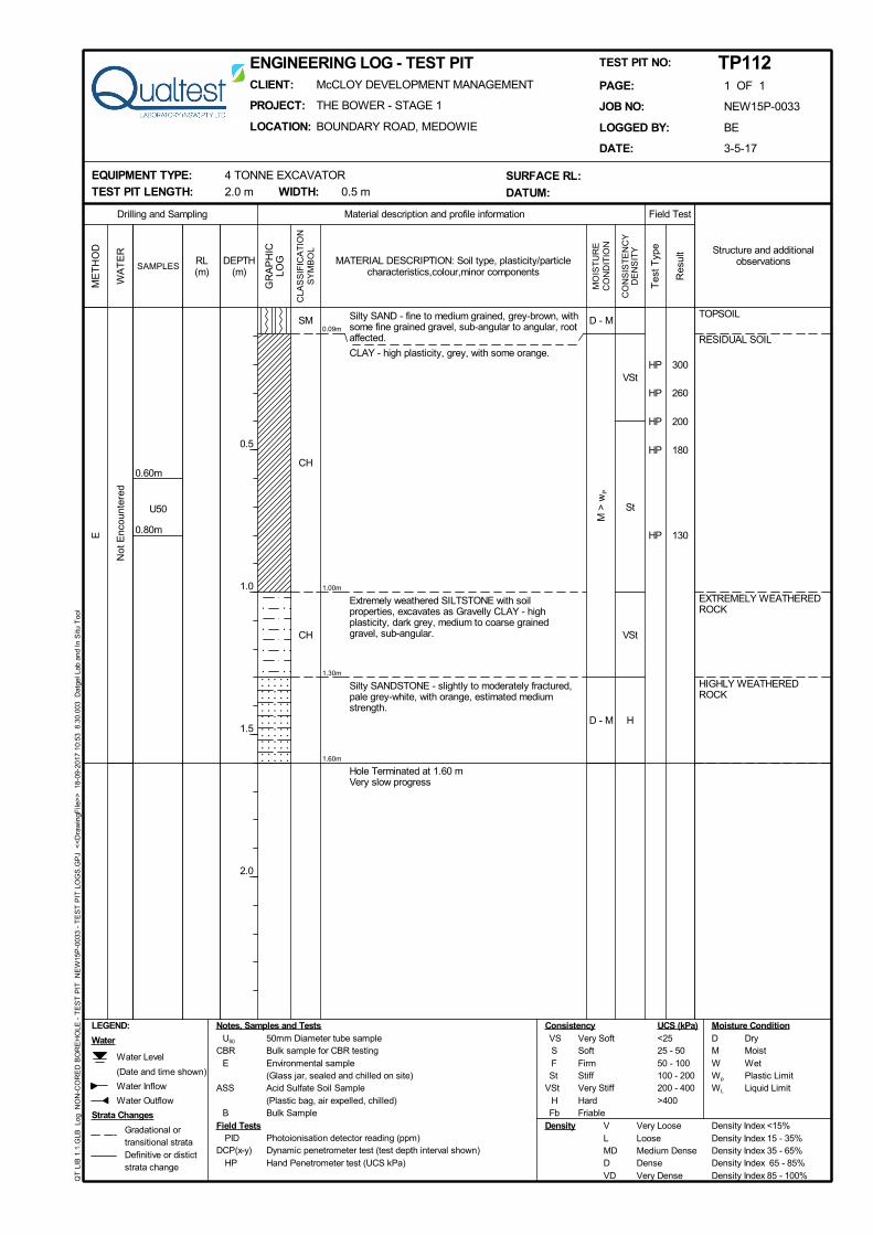
VSt
St
VSt
H
0.09m
1.00m
1.30m
1.60m
TOPSOIL
RESIDUAL SOIL
EXTREMELY WEATHEREDROCK
HIGHLY WEATHEREDROCK
E
SM
CH
CH
M >
wP
D - M
D - M
U50
0.80m
0.60m
Silty SAND - fine to medium grained, grey-brown, withsome fine grained gravel, sub-angular to angular, rootaffected.
CLAY - high plasticity, grey, with some orange.
Extremely weathered SILTSTONE with soilproperties, excavates as Gravelly CLAY - highplasticity, dark grey, medium to coarse grainedgravel, sub-angular.
Silty SANDSTONE - slightly to moderately fractured,pale grey-white, with orange, estimated mediumstrength.
Hole Terminated at 1.60 mVery slow progress
HP 300
HP 260
HP 200
HP 180
HP 130
Not
Enc
ount
ered
Field Test
PID Photoionisation detector reading (ppm)DCP(x-y) Dynamic penetrometer test (test depth interval shown)
HP Hand Penetrometer test (UCS kPa)
Material description and profile information
UCS (kPa)D DryM MoistW WetWp Plastic LimitWL Liquid Limit
Field Tests
Notes, Samples and Tests
Structure and additionalobservations
ME
TH
OD
CLA
SS
IFIC
AT
ION
SY
MB
OL
Tes
t Typ
e
MO
IST
UR
EC
ON
DIT
ION
CO
NS
IST
EN
CY
DE
NS
ITY
Water
WA
TE
R
Gradational ortransitional strataDefinitive or distictstrata change
Strata Changes
RL(m)
GR
AP
HIC
LOGDEPTH
(m)
0.5
1.0
1.5
2.0
SAMPLES
Water Level
(Date and time shown)
Water Inflow
Water Outflow
VS Very SoftS SoftF FirmSt Stiff
VSt Very StiffH HardFb Friable
U50 50mm Diameter tube sampleCBR Bulk sample for CBR testing
E Environmental sample(Glass jar, sealed and chilled on site)
ASS Acid Sulfate Soil Sample(Plastic bag, air expelled, chilled)
B Bulk Sample
Consistency Moisture Condition
V Very Loose Density Index <15%L Loose Density Index 15 - 35%MD Medium Dense Density Index 35 - 65%D Dense Density Index 65 - 85%VD Very Dense Density Index 85 - 100%
Density
LEGEND:
Res
ult
MATERIAL DESCRIPTION: Soil type, plasticity/particlecharacteristics,colour,minor components
Drilling and Sampling
<2525 - 5050 - 100100 - 200200 - 400>400
QT
LIB
1.1
.GLB
Lo
g N
ON
-CO
RE
D B
OR
EH
OLE
- T
ES
T P
IT
NE
W15
P-0
033
- T
ES
T P
IT L
OG
S.G
PJ
<<
Dra
win
gFile
>>
18
-09-
2017
10:
53
8.30
.003
D
atge
l Lab
and
In
Situ
Too
l
CLIENT: McCLOY DEVELOPMENT MANAGEMENT
PROJECT: THE BOWER - STAGE 1
LOCATION: BOUNDARY ROAD, MEDOWIE
ENGINEERING LOG - TEST PIT
EQUIPMENT TYPE: 4 TONNE EXCAVATOR
TEST PIT LENGTH: 2.0 m WIDTH: 0.5 m
PAGE: 1 OF 1
JOB NO: NEW15P-0033
LOGGED BY: BE
DATE: 3-5-17
TEST PIT NO: TP112
SURFACE RL:
DATUM:

VSt
H
0.20m
1.50m
1.80m
TOPSOIL
RESIDUAL SOIL
EXTREMELY WEATHEREDROCK
E
CL
CH
M <
wP
M >
wP
D - M
U50
0.60m
0.40m
Sandy CLAY - low to medium plasticity, dark brown,fine to medium grained sand, root affected.
CLAY - high plasticity, pale grey with some palebrown to orange, trace to some fine to mediumgrained sand.
Extremely weathered Silty SANDSTONE able to bebroken down into Sandy CLAY - medium plasticity,pale grey to white with some pale brown to orange.
Hole Terminated at 1.80 m
HP 230
HP 210
HP 370
Not
Enc
ount
ered
Field Test
PID Photoionisation detector reading (ppm)DCP(x-y) Dynamic penetrometer test (test depth interval shown)
HP Hand Penetrometer test (UCS kPa)
Material description and profile information
UCS (kPa)D DryM MoistW WetWp Plastic LimitWL Liquid Limit
Field Tests
Notes, Samples and Tests
Structure and additionalobservations
ME
TH
OD
CLA
SS
IFIC
AT
ION
SY
MB
OL
Tes
t Typ
e
MO
IST
UR
EC
ON
DIT
ION
CO
NS
IST
EN
CY
DE
NS
ITY
Water
WA
TE
R
Gradational ortransitional strataDefinitive or distictstrata change
Strata Changes
RL(m)
GR
AP
HIC
LOGDEPTH
(m)
0.5
1.0
1.5
2.0
SAMPLES
Water Level
(Date and time shown)
Water Inflow
Water Outflow
VS Very SoftS SoftF FirmSt Stiff
VSt Very StiffH HardFb Friable
U50 50mm Diameter tube sampleCBR Bulk sample for CBR testing
E Environmental sample(Glass jar, sealed and chilled on site)
ASS Acid Sulfate Soil Sample(Plastic bag, air expelled, chilled)
B Bulk Sample
Consistency Moisture Condition
V Very Loose Density Index <15%L Loose Density Index 15 - 35%MD Medium Dense Density Index 35 - 65%D Dense Density Index 65 - 85%VD Very Dense Density Index 85 - 100%
Density
LEGEND:
Res
ult
MATERIAL DESCRIPTION: Soil type, plasticity/particlecharacteristics,colour,minor components
Drilling and Sampling
<2525 - 5050 - 100100 - 200200 - 400>400
QT
LIB
1.1
.GLB
Lo
g N
ON
-CO
RE
D B
OR
EH
OLE
- T
ES
T P
IT
NE
W15
P-0
033
TP
Q09
TO
TP
Q44
.GP
J <
<D
raw
ingF
ile>
>
18-0
9-20
17 1
0:57
8.
30.0
03
Dat
gel L
ab a
nd I
n S
itu T
ool
CLIENT: McCLOY MEDOWIE PTY LTD
PROJECT: PROPOSED SUBDIVISION
LOCATION: BOUNDARY ROAD, MEDOWIE
ENGINEERING LOG - TEST PIT
EQUIPMENT TYPE: 5t Excavator (Eurocomach)
TEST PIT LENGTH: 1.5 m WIDTH: 0.3 m
PAGE: 1 OF 1
JOB NO: NEW15P-0033
LOGGED BY: SJK
DATE: 24-11-15
TEST PIT NO: TP-Q39
SURFACE RL:
DATUM:

VSt
St
H
0.20m
0.80m
1.50m
TOPSOIL
RESIDUAL SOIL
HIGHLY WEATHEREDROCK
E
CL
CH
M <
wP
M >
wP
M
U500.45m
0.30m
Sandy CLAY - low to medium plasticity, dark brown,fine to medium grained sand, root affected.
CLAY - high plasticity, grey and pale brown, trace offine to medium grained sand.
Pale grey and pale brown.
SILTSTONE - pale grey and brown, fractured,estimated low to medium strength.
Hole Terminated at 1.50 mSlow progress
HP 300
HP 170
Not
Enc
ount
ered
Field Test
PID Photoionisation detector reading (ppm)DCP(x-y) Dynamic penetrometer test (test depth interval shown)
HP Hand Penetrometer test (UCS kPa)
Material description and profile information
UCS (kPa)D DryM MoistW WetWp Plastic LimitWL Liquid Limit
Field Tests
Notes, Samples and Tests
Structure and additionalobservations
ME
TH
OD
CLA
SS
IFIC
AT
ION
SY
MB
OL
Tes
t Typ
e
MO
IST
UR
EC
ON
DIT
ION
CO
NS
IST
EN
CY
DE
NS
ITY
Water
WA
TE
R
Gradational ortransitional strataDefinitive or distictstrata change
Strata Changes
RL(m)
GR
AP
HIC
LOGDEPTH
(m)
0.5
1.0
1.5
2.0
SAMPLES
Water Level
(Date and time shown)
Water Inflow
Water Outflow
VS Very SoftS SoftF FirmSt Stiff
VSt Very StiffH HardFb Friable
U50 50mm Diameter tube sampleCBR Bulk sample for CBR testing
E Environmental sample(Glass jar, sealed and chilled on site)
ASS Acid Sulfate Soil Sample(Plastic bag, air expelled, chilled)
B Bulk Sample
Consistency Moisture Condition
V Very Loose Density Index <15%L Loose Density Index 15 - 35%MD Medium Dense Density Index 35 - 65%D Dense Density Index 65 - 85%VD Very Dense Density Index 85 - 100%
Density
LEGEND:
Res
ult
MATERIAL DESCRIPTION: Soil type, plasticity/particlecharacteristics,colour,minor components
Drilling and Sampling
<2525 - 5050 - 100100 - 200200 - 400>400
QT
LIB
1.1
.GLB
Lo
g N
ON
-CO
RE
D B
OR
EH
OLE
- T
ES
T P
IT
NE
W15
P-0
033
TP
Q09
TO
TP
Q44
.GP
J <
<D
raw
ingF
ile>
>
18-0
9-20
17 1
0:57
8.
30.0
03
Dat
gel L
ab a
nd I
n S
itu T
ool
CLIENT: McCLOY MEDOWIE PTY LTD
PROJECT: PROPOSED SUBDIVISION
LOCATION: BOUNDARY ROAD, MEDOWIE
ENGINEERING LOG - TEST PIT
EQUIPMENT TYPE: 5t Excavator (Eurocomach)
TEST PIT LENGTH: 1.5 m WIDTH: 0.3 m
PAGE: 1 OF 1
JOB NO: NEW15P-0033
LOGGED BY: SJK
DATE: 24-11-15
TEST PIT NO: TP-Q40
SURFACE RL:
DATUM:

St /VSt
H
0.20m
0.85m
1.25m
TOPSOIL
RESIDUAL SOIL
EXTREMELY TO HIGHLYWEATHERED ROCK
E
CL
CH
M ~
wP
M >
wP
M
U500.50m
0.35m
Sandy CLAY - low to medium plasticity, dark brown,fine to medium grained sand, root affected.
CLAY - high plasticity, grey with some pale brown,trace of fine to medium grained sand.
SANDSTONE - fine to medium grained, pale grey towhite and pale brown to orange, estimated lowstrength.
Hole Terminated at 1.25 mVery slow progress
HP 230
HP 200
HP 180Not
Enc
ount
ered
Field Test
PID Photoionisation detector reading (ppm)DCP(x-y) Dynamic penetrometer test (test depth interval shown)
HP Hand Penetrometer test (UCS kPa)
Material description and profile information
UCS (kPa)D DryM MoistW WetWp Plastic LimitWL Liquid Limit
Field Tests
Notes, Samples and Tests
Structure and additionalobservations
ME
TH
OD
CLA
SS
IFIC
AT
ION
SY
MB
OL
Tes
t Typ
e
MO
IST
UR
EC
ON
DIT
ION
CO
NS
IST
EN
CY
DE
NS
ITY
Water
WA
TE
R
Gradational ortransitional strataDefinitive or distictstrata change
Strata Changes
RL(m)
GR
AP
HIC
LOGDEPTH
(m)
0.5
1.0
1.5
2.0
SAMPLES
Water Level
(Date and time shown)
Water Inflow
Water Outflow
VS Very SoftS SoftF FirmSt Stiff
VSt Very StiffH HardFb Friable
U50 50mm Diameter tube sampleCBR Bulk sample for CBR testing
E Environmental sample(Glass jar, sealed and chilled on site)
ASS Acid Sulfate Soil Sample(Plastic bag, air expelled, chilled)
B Bulk Sample
Consistency Moisture Condition
V Very Loose Density Index <15%L Loose Density Index 15 - 35%MD Medium Dense Density Index 35 - 65%D Dense Density Index 65 - 85%VD Very Dense Density Index 85 - 100%
Density
LEGEND:
Res
ult
MATERIAL DESCRIPTION: Soil type, plasticity/particlecharacteristics,colour,minor components
Drilling and Sampling
<2525 - 5050 - 100100 - 200200 - 400>400
QT
LIB
1.1
.GLB
Lo
g N
ON
-CO
RE
D B
OR
EH
OLE
- T
ES
T P
IT
NE
W15
P-0
033
TP
Q09
TO
TP
Q44
.GP
J <
<D
raw
ingF
ile>
>
18-0
9-20
17 1
0:57
8.
30.0
03
Dat
gel L
ab a
nd I
n S
itu T
ool
CLIENT: McCLOY MEDOWIE PTY LTD
PROJECT: PROPOSED SUBDIVISION
LOCATION: BOUNDARY ROAD, MEDOWIE
ENGINEERING LOG - TEST PIT
EQUIPMENT TYPE: 5t Excavator (Eurocomach)
TEST PIT LENGTH: 1.5 m WIDTH: 0.3 m
PAGE: 1 OF 1
JOB NO: NEW15P-0033
LOGGED BY: SJK
DATE: 24-11-15
TEST PIT NO: TP-Q41
SURFACE RL:
DATUM:

St
H
0.15m
0.70m
1.90m
TOPSOIL
RESIDUAL SOIL
EXTREMELY TO HIGHLYWEATHERED ROCK
E
CL
CH
M ~
wP
M >
wP
M
U50
0.45m
0.20m
Sandy CLAY - low to medium plasticity, dark brown,fine to medium grained sand, root affected.
CLAY - high plasticity, grey with some pale brown,trace of fine to medium grained sand.
Silty SANDSTONE - fine to medium grained, palegrey to white, fractured with weathered defects /residual soil / extremely weathered pockets,estimated strength varies from very low to high.
Becoming mostly extremely weathered.
Some brown semi-carbonaceous layers.
Hole Terminated at 1.90 m
HP 200
HP 150
Not
Enc
ount
ered
Field Test
PID Photoionisation detector reading (ppm)DCP(x-y) Dynamic penetrometer test (test depth interval shown)
HP Hand Penetrometer test (UCS kPa)
Material description and profile information
UCS (kPa)D DryM MoistW WetWp Plastic LimitWL Liquid Limit
Field Tests
Notes, Samples and Tests
Structure and additionalobservations
ME
TH
OD
CLA
SS
IFIC
AT
ION
SY
MB
OL
Tes
t Typ
e
MO
IST
UR
EC
ON
DIT
ION
CO
NS
IST
EN
CY
DE
NS
ITY
Water
WA
TE
R
Gradational ortransitional strataDefinitive or distictstrata change
Strata Changes
RL(m)
GR
AP
HIC
LOGDEPTH
(m)
0.5
1.0
1.5
2.0
SAMPLES
Water Level
(Date and time shown)
Water Inflow
Water Outflow
VS Very SoftS SoftF FirmSt Stiff
VSt Very StiffH HardFb Friable
U50 50mm Diameter tube sampleCBR Bulk sample for CBR testing
E Environmental sample(Glass jar, sealed and chilled on site)
ASS Acid Sulfate Soil Sample(Plastic bag, air expelled, chilled)
B Bulk Sample
Consistency Moisture Condition
V Very Loose Density Index <15%L Loose Density Index 15 - 35%MD Medium Dense Density Index 35 - 65%D Dense Density Index 65 - 85%VD Very Dense Density Index 85 - 100%
Density
LEGEND:
Res
ult
MATERIAL DESCRIPTION: Soil type, plasticity/particlecharacteristics,colour,minor components
Drilling and Sampling
<2525 - 5050 - 100100 - 200200 - 400>400
QT
LIB
1.1
.GLB
Lo
g N
ON
-CO
RE
D B
OR
EH
OLE
- T
ES
T P
IT
NE
W15
P-0
033
TP
Q09
TO
TP
Q44
.GP
J <
<D
raw
ingF
ile>
>
18-0
9-20
17 1
0:57
8.
30.0
03
Dat
gel L
ab a
nd I
n S
itu T
ool
CLIENT: McCLOY MEDOWIE PTY LTD
PROJECT: PROPOSED SUBDIVISION
LOCATION: BOUNDARY ROAD, MEDOWIE
ENGINEERING LOG - TEST PIT
EQUIPMENT TYPE: 5t Excavator (Eurocomach)
TEST PIT LENGTH: 1.5 m WIDTH: 0.3 m
PAGE: 1 OF 1
JOB NO: NEW15P-0033
LOGGED BY: SJK
DATE: 24-11-15
TEST PIT NO: TP-Q42
SURFACE RL:
DATUM:

APPENDIX B:
Results of Laboratory Testing

Sample DetailsSample ID: NEW17W-3759--S01 Client Sample ID:
Test Request No.: - Sampling Method: AS1289.1.2.1 cl 6.4b
Material: Clay Date Sampled: 23/08/2017
Source: On-Site Date Submitted: 28/08/2017
Specification: No Specification
Project Location: Boundary Road, Medowie, NSW
Sample Location: TP201 - (0.4 - 0.6m)
Borehole Number: TP201
Borehole Depth (m): 0.4 - 0.6
Shrink Test AS 1289.7.1.1Shrink on drying (%): 7.7
Shrinkage Moisture Content (%): 32.4
Est. inert material (%): 0%
Crumbling during shrinkage: Nil
Cracking during shrinkage: Nil
Swell Test AS 1289.7.1.1Swell on Saturation (%): -0.1
Moisture Content before (%): 36.3
Moisture Content after (%): 36.2
Est. Unc. Comp. Strength before (kPa): 400
Est. Unc. Comp. Strength after (kPa): 220
Shrink Swell
Shrink Swell Index - Iss (%): 4.3
Accredited for compliance with ISO/IEC 17025 -TestingThe results of the tests, calibrations and/ormeasurements included in this document are traceableto Australian/national standards
6/09/2017
Shrink Swell Index Report
Report No: SSI:NEW17W-3759--S01
Issue No: 1
Client:
Date of Issue:
NATA Accredited Laboratory Number: 18686
Approved Signatory: Dane Cullen
(Senior Geotechnician)Project Name: Stage 2 The Bower
F: 02 4960 9775
QUALTEST Laboratory (NSW) Pty Ltd (20708)
T: 02 4968 4468
E: [email protected]: www.qualtest.com.auABN: 98 153 268 896
8 Ironbark Close Warabrook NSW 2304
Project No.: NEW15P-0033A
Principal:
Suite 1 Level 3, 426 King StreetNewcastle West NSW 2300
McCloy Development Management Pty Ltd
Page 1 of 1Form No: 18932, Report No: SSI:NEW17W-3759--S01 © 2000-2013 QESTLab by SpectraQEST.com
Comments

Sample DetailsSample ID: NEW17W-3759--S02 Client Sample ID:
Test Request No.: - Sampling Method: AS1289.1.2.1 cl 6.4b
Material: Clay Date Sampled: 23/08/2017
Source: On-Site Date Submitted: 28/08/2017
Specification: No Specification
Project Location: Boundary Road, Medowie, NSW
Sample Location: TP202 - (0.6 - 0.8m)
Borehole Number: TP202
Borehole Depth (m): 0.6 - 0.8
Shrink Test AS 1289.7.1.1Shrink on drying (%): 9.8
Shrinkage Moisture Content (%): 42.8
Est. inert material (%): 5%
Crumbling during shrinkage: Nil
Cracking during shrinkage: Nil
Swell Test AS 1289.7.1.1Swell on Saturation (%): -0.4
Moisture Content before (%): 43.9
Moisture Content after (%): 43.2
Est. Unc. Comp. Strength before (kPa): 270
Est. Unc. Comp. Strength after (kPa): 190
Shrink Swell
Shrink Swell Index - Iss (%): 5.4
Accredited for compliance with ISO/IEC 17025 -TestingThe results of the tests, calibrations and/ormeasurements included in this document are traceableto Australian/national standards
6/09/2017
Shrink Swell Index Report
Report No: SSI:NEW17W-3759--S02
Issue No: 1
Client:
Date of Issue:
NATA Accredited Laboratory Number: 18686
Approved Signatory: Dane Cullen
(Senior Geotechnician)Project Name: Stage 2 The Bower
F: 02 4960 9775
QUALTEST Laboratory (NSW) Pty Ltd (20708)
T: 02 4968 4468
E: [email protected]: www.qualtest.com.auABN: 98 153 268 896
8 Ironbark Close Warabrook NSW 2304
Project No.: NEW15P-0033A
Principal:
Suite 1 Level 3, 426 King StreetNewcastle West NSW 2300
McCloy Development Management Pty Ltd
Page 1 of 1Form No: 18932, Report No: SSI:NEW17W-3759--S02 © 2000-2013 QESTLab by SpectraQEST.com
Comments
Sample DetailsSample ID: NEW17W-3759--S03 Client Sample ID:
Test Request No.: - Sampling Method: AS1289.1.2.1 cl 6.4b
Material: Clay Date Sampled: 23/08/2017
Source: On-Site Date Submitted: 28/08/2017
Specification: No Specification
Project Location: Boundary Road, Medowie, NSW
Sample Location: TP203 - (0.15 - 0.35m)
Borehole Number: TP203
Borehole Depth (m): 0.15 - 0.35
Shrink Test AS 1289.7.1.1Shrink on drying (%): 7.1
Shrinkage Moisture Content (%): 37.9
Est. inert material (%): 5%
Crumbling during shrinkage: Nil
Cracking during shrinkage: Moderate
Swell Test AS 1289.7.1.1Swell on Saturation (%): 0.3
Moisture Content before (%): 37.0
Moisture Content after (%): 36.3
Est. Unc. Comp. Strength before (kPa): 410
Est. Unc. Comp. Strength after (kPa): 220
Shrink Swell
Shrink Swell Index - Iss (%): 4.0
Accredited for compliance with ISO/IEC 17025 -TestingThe results of the tests, calibrations and/ormeasurements included in this document are traceableto Australian/national standards
6/09/2017
Shrink Swell Index Report
Report No: SSI:NEW17W-3759--S03
Issue No: 1
Client:
Date of Issue:
NATA Accredited Laboratory Number: 18686
Approved Signatory: Dane Cullen
(Senior Geotechnician)Project Name: Stage 2 The Bower
F: 02 4960 9775
QUALTEST Laboratory (NSW) Pty Ltd (20708)
T: 02 4968 4468
E: [email protected]: www.qualtest.com.auABN: 98 153 268 896
8 Ironbark Close Warabrook NSW 2304
Project No.: NEW15P-0033A
Principal:
Suite 1 Level 3, 426 King StreetNewcastle West NSW 2300
McCloy Development Management Pty Ltd
Page 1 of 1Form No: 18932, Report No: SSI:NEW17W-3759--S03 © 2000-2013 QESTLab by SpectraQEST.com
Comments

Sample DetailsSample ID: NEW17W-3759--S04 Client Sample ID:
Test Request No.: - Sampling Method: AS1289.1.2.1 cl 6.4b
Material: Clay Date Sampled: 23/08/2017
Source: On-Site Date Submitted: 28/08/2017
Specification: No Specification
Project Location: Boundary Road, Medowie, NSW
Sample Location: TP204 - (0.2 - 0.35m)
Borehole Number: TP204
Borehole Depth (m): 0.2 - 0.35
Shrink Test AS 1289.7.1.1Shrink on drying (%): 8.0
Shrinkage Moisture Content (%): 36.2
Est. inert material (%): 0%
Crumbling during shrinkage: Nil
Cracking during shrinkage: Minor
Swell Test AS 1289.7.1.1Swell on Saturation (%): -0.4
Moisture Content before (%): 34.8
Moisture Content after (%): 43.1
Est. Unc. Comp. Strength before (kPa): 210
Est. Unc. Comp. Strength after (kPa): 230
Shrink Swell
Shrink Swell Index - Iss (%): 4.5
Accredited for compliance with ISO/IEC 17025 -TestingThe results of the tests, calibrations and/ormeasurements included in this document are traceableto Australian/national standards
6/09/2017
Shrink Swell Index Report
Report No: SSI:NEW17W-3759--S04
Issue No: 1
Client:
Date of Issue:
NATA Accredited Laboratory Number: 18686
Approved Signatory: Dane Cullen
(Senior Geotechnician)Project Name: Stage 2 The Bower
F: 02 4960 9775
QUALTEST Laboratory (NSW) Pty Ltd (20708)
T: 02 4968 4468
E: [email protected]: www.qualtest.com.auABN: 98 153 268 896
8 Ironbark Close Warabrook NSW 2304
Project No.: NEW15P-0033A
Principal:
Suite 1 Level 3, 426 King StreetNewcastle West NSW 2300
McCloy Development Management Pty Ltd
Page 1 of 1Form No: 18932, Report No: SSI:NEW17W-3759--S04 © 2000-2013 QESTLab by SpectraQEST.com
Comments

Sample DetailsSample ID: NEW17W-3759--S05 Client Sample ID:
Test Request No.: - Sampling Method: AS1289.1.2.1 cl 6.4b
Material: Clay Date Sampled: 23/08/2017
Source: On-Site Date Submitted: 28/08/2017
Specification: No Specification
Project Location: Boundary Road, Medowie, NSW
Sample Location: TP205 - (0.2 - 0.4m)
Borehole Number: TP205
Borehole Depth (m): 0.2 - 0.4
Shrink Test AS 1289.7.1.1Shrink on drying (%): 6.2
Shrinkage Moisture Content (%): 32.9
Est. inert material (%): 0%
Crumbling during shrinkage: Minor
Cracking during shrinkage: Moderate
Swell Test AS 1289.7.1.1Swell on Saturation (%): 0.0
Moisture Content before (%): 27.3
Moisture Content after (%): 30.4
Est. Unc. Comp. Strength before (kPa): 600
Est. Unc. Comp. Strength after (kPa): 350
Shrink Swell
Shrink Swell Index - Iss (%): 3.4
Accredited for compliance with ISO/IEC 17025 -TestingThe results of the tests, calibrations and/ormeasurements included in this document are traceableto Australian/national standards
6/09/2017
Shrink Swell Index Report
Report No: SSI:NEW17W-3759--S05
Issue No: 1
Client:
Date of Issue:
NATA Accredited Laboratory Number: 18686
Approved Signatory: Dane Cullen
(Senior Geotechnician)Project Name: Stage 2 The Bower
F: 02 4960 9775
QUALTEST Laboratory (NSW) Pty Ltd (20708)
T: 02 4968 4468
E: [email protected]: www.qualtest.com.auABN: 98 153 268 896
8 Ironbark Close Warabrook NSW 2304
Project No.: NEW15P-0033A
Principal:
Suite 1 Level 3, 426 King StreetNewcastle West NSW 2300
McCloy Development Management Pty Ltd
Page 1 of 1Form No: 18932, Report No: SSI:NEW17W-3759--S05 © 2000-2013 QESTLab by SpectraQEST.com
Comments

Sample DetailsSample ID: NEW17W-3759--S06 Client Sample ID:
Test Request No.: - Sampling Method: AS1289.1.2.1 cl 6.4b
Material: Clay Date Sampled: 23/08/2017
Source: On-Site Date Submitted: 28/08/2017
Specification: No Specification
Project Location: Boundary Road, Medowie, NSW
Sample Location: TP206 - (0.25 - 0.5m)
Borehole Number: TP206
Borehole Depth (m): 0.25 - 0.5
Shrink Test AS 1289.7.1.1Shrink on drying (%): 8.2
Shrinkage Moisture Content (%): 39.7
Est. inert material (%): 5%
Crumbling during shrinkage: Nil
Cracking during shrinkage: Minor
Swell Test AS 1289.7.1.1Swell on Saturation (%): 0.1
Moisture Content before (%): 44.1
Moisture Content after (%): 41.6
Est. Unc. Comp. Strength before (kPa): 240
Est. Unc. Comp. Strength after (kPa): 190
Shrink Swell
Shrink Swell Index - Iss (%): 4.6
Accredited for compliance with ISO/IEC 17025 -TestingThe results of the tests, calibrations and/ormeasurements included in this document are traceableto Australian/national standards
6/09/2017
Shrink Swell Index Report
Report No: SSI:NEW17W-3759--S06
Issue No: 1
Client:
Date of Issue:
NATA Accredited Laboratory Number: 18686
Approved Signatory: Dane Cullen
(Senior Geotechnician)Project Name: Stage 2 The Bower
F: 02 4960 9775
QUALTEST Laboratory (NSW) Pty Ltd (20708)
T: 02 4968 4468
E: [email protected]: www.qualtest.com.auABN: 98 153 268 896
8 Ironbark Close Warabrook NSW 2304
Project No.: NEW15P-0033A
Principal:
Suite 1 Level 3, 426 King StreetNewcastle West NSW 2300
McCloy Development Management Pty Ltd
Page 1 of 1Form No: 18932, Report No: SSI:NEW17W-3759--S06 © 2000-2013 QESTLab by SpectraQEST.com
Comments

Sample DetailsSample ID: NEW17W-3759--S07 Client Sample ID:
Test Request No.: - Sampling Method: AS1289.1.2.1 cl 6.4b
Material: Clay Date Sampled: 23/08/2017
Source: On-Site Date Submitted: 28/08/2017
Specification: No Specification
Project Location: Boundary Road, Medowie, NSW
Sample Location: TP207 - (0.2 - 0.35m)
Borehole Number: TP207
Borehole Depth (m): 0.2 - 0.35
Shrink Test AS 1289.7.1.1Shrink on drying (%): 5.1
Shrinkage Moisture Content (%): 30.5
Est. inert material (%): 10%
Crumbling during shrinkage: Nil
Cracking during shrinkage: Moderate
Swell Test AS 1289.7.1.1Swell on Saturation (%): -0.4
Moisture Content before (%): 32.2
Moisture Content after (%): 35.2
Est. Unc. Comp. Strength before (kPa): 300
Est. Unc. Comp. Strength after (kPa): 140
Shrink Swell
Shrink Swell Index - Iss (%): 2.9
Accredited for compliance with ISO/IEC 17025 -TestingThe results of the tests, calibrations and/ormeasurements included in this document are traceableto Australian/national standards
6/09/2017
Shrink Swell Index Report
Report No: SSI:NEW17W-3759--S07
Issue No: 1
Client:
Date of Issue:
NATA Accredited Laboratory Number: 18686
Approved Signatory: Dane Cullen
(Senior Geotechnician)Project Name: Stage 2 The Bower
F: 02 4960 9775
QUALTEST Laboratory (NSW) Pty Ltd (20708)
T: 02 4968 4468
E: [email protected]: www.qualtest.com.auABN: 98 153 268 896
8 Ironbark Close Warabrook NSW 2304
Project No.: NEW15P-0033A
Principal:
Suite 1 Level 3, 426 King StreetNewcastle West NSW 2300
McCloy Development Management Pty Ltd
Page 1 of 1Form No: 18932, Report No: SSI:NEW17W-3759--S07 © 2000-2013 QESTLab by SpectraQEST.com
Comments

Sample DetailsSample ID: NEW17W-3759--S08 Client Sample ID:
Test Request No.: - Sampling Method: AS1289.1.2.1 cl 6.4b
Material: Clay Date Sampled: 23/08/2017
Source: On-Site Date Submitted: 28/08/2017
Specification: No Specification
Project Location: Boundary Road, Medowie, NSW
Sample Location: TP208 - (0.4 - 0.6m)
Borehole Number: TP208
Borehole Depth (m): 0.4 - 0.6
Shrink Test AS 1289.7.1.1Shrink on drying (%): 8.1
Shrinkage Moisture Content (%): 35.5
Est. inert material (%): 0%
Crumbling during shrinkage: Nil
Cracking during shrinkage: Minor
Swell Test AS 1289.7.1.1Swell on Saturation (%): -0.2
Moisture Content before (%): 38.0
Moisture Content after (%): 37.5
Est. Unc. Comp. Strength before (kPa): 250
Est. Unc. Comp. Strength after (kPa): 150
Shrink Swell
Shrink Swell Index - Iss (%): 4.5
Accredited for compliance with ISO/IEC 17025 -TestingThe results of the tests, calibrations and/ormeasurements included in this document are traceableto Australian/national standards
6/09/2017
Shrink Swell Index Report
Report No: SSI:NEW17W-3759--S08
Issue No: 1
Client:
Date of Issue:
NATA Accredited Laboratory Number: 18686
Approved Signatory: Dane Cullen
(Senior Geotechnician)Project Name: Stage 2 The Bower
F: 02 4960 9775
QUALTEST Laboratory (NSW) Pty Ltd (20708)
T: 02 4968 4468
E: [email protected]: www.qualtest.com.auABN: 98 153 268 896
8 Ironbark Close Warabrook NSW 2304
Project No.: NEW15P-0033A
Principal:
Suite 1 Level 3, 426 King StreetNewcastle West NSW 2300
McCloy Development Management Pty Ltd
Page 1 of 1Form No: 18932, Report No: SSI:NEW17W-3759--S08 © 2000-2013 QESTLab by SpectraQEST.com
Comments

Sample DetailsSample ID: NEW17W-3759--S09 Client Sample ID:
Test Request No.: - Sampling Method: AS1289.1.2.1 cl 6.4b
Material: Clay Date Sampled: 23/08/2017
Source: On-Site Date Submitted: 28/08/2017
Specification: No Specification
Project Location: Boundary Road, Medowie, NSW
Sample Location: TP209 - (1.0 -1.2m)
Borehole Number: TP209
Borehole Depth (m): 1.0 - 1.2m
Shrink Test AS 1289.7.1.1Shrink on drying (%): 5.3
Shrinkage Moisture Content (%): 33.8
Est. inert material (%): 0%
Crumbling during shrinkage: Nil
Cracking during shrinkage: Moderate
Swell Test AS 1289.7.1.1Swell on Saturation (%): 4.0
Moisture Content before (%): 31.5
Moisture Content after (%): 35.6
Est. Unc. Comp. Strength before (kPa): 480
Est. Unc. Comp. Strength after (kPa): 180
Shrink Swell
Shrink Swell Index - Iss (%): 4.0
Accredited for compliance with ISO/IEC 17025 -TestingThe results of the tests, calibrations and/ormeasurements included in this document are traceableto Australian/national standards
11/09/2017
Shrink Swell Index Report
Report No: SSI:NEW17W-3759--S09
Issue No: 1
Client:
Date of Issue:
NATA Accredited Laboratory Number: 18686
Approved Signatory: Dane Cullen
(Senior Geotechnician)Project Name: Stage 2 The Bower
F: 02 4960 9775
QUALTEST Laboratory (NSW) Pty Ltd (20708)
T: 02 4968 4468
E: [email protected]: www.qualtest.com.auABN: 98 153 268 896
8 Ironbark Close Warabrook NSW 2304
Project No.: NEW15P-0033A
Principal:
Suite 1 Level 3, 426 King StreetNewcastle West NSW 2300
McCloy Development Management Pty Ltd
Page 1 of 1Form No: 18932, Report No: SSI:NEW17W-3759--S09 © 2000-2013 QESTLab by SpectraQEST.com
Comments

Sample DetailsSample ID: NEW17W-3759--S10 Client Sample ID:
Test Request No.: - Sampling Method: AS1289.1.2.1 cl 6.4b
Material: Clay Date Sampled: 23/08/2017
Source: On-Site Date Submitted: 28/08/2017
Specification: No Specification
Project Location: Boundary Road, Medowie, NSW
Sample Location: TP210 - (0.8 - 0.95m)
Borehole Number: TP210
Borehole Depth (m): 0.8 - 0.95
Shrink Test AS 1289.7.1.1Shrink on drying (%): 5.0
Shrinkage Moisture Content (%): 26.3
Est. inert material (%): 1%
Crumbling during shrinkage: Nil
Cracking during shrinkage: Nil
Swell Test AS 1289.7.1.1Swell on Saturation (%): -0.2
Moisture Content before (%): 27.1
Moisture Content after (%): 27.1
Est. Unc. Comp. Strength before (kPa): 470
Est. Unc. Comp. Strength after (kPa): 520
Shrink Swell
Shrink Swell Index - Iss (%): 2.8
Accredited for compliance with ISO/IEC 17025 -TestingThe results of the tests, calibrations and/ormeasurements included in this document are traceableto Australian/national standards
11/09/2017
Shrink Swell Index Report
Report No: SSI:NEW17W-3759--S10
Issue No: 1
Client:
Date of Issue:
NATA Accredited Laboratory Number: 18686
Approved Signatory: Dane Cullen
(Senior Geotechnician)Project Name: Stage 2 The Bower
F: 02 4960 9775
QUALTEST Laboratory (NSW) Pty Ltd (20708)
T: 02 4968 4468
E: [email protected]: www.qualtest.com.auABN: 98 153 268 896
8 Ironbark Close Warabrook NSW 2304
Project No.: NEW15P-0033A
Principal:
Suite 1 Level 3, 426 King StreetNewcastle West NSW 2300
McCloy Development Management Pty Ltd
Page 1 of 1Form No: 18932, Report No: SSI:NEW17W-3759--S10 © 2000-2013 QESTLab by SpectraQEST.com
Comments

On-Site Source:ClayMaterial:
Sample Details
NEW17W-3759--S11Sample ID:
23/08/2017Date Sampled:
No SpecificationSpecification:Boundary Road, Medowie, NSWProject Location:-Lot. No
-TRN
AS1289.1.2.1 cl 6.4bSampling Method:
TP211 - (0.2 - 0.5m)Sample Location:
Test Results
4323
Four Point66
YesNoNo
25013.0
Dry Sieved250
ResultSample History AS 1289.1.1
MethodDescription Limits
Preparation AS 1289.1.1 Linear Shrinkage (%) AS 1289.3.4.1Mould Length (mm)CrumblingCurlingCrackingLiquid Limit (%) AS 1289.3.1.1MethodPlastic Limit (%) AS 1289.3.2.1Plasticity Index (%) AS 1289.3.3.1
Accredited for compliance with ISO/IEC 17025 -TestingThe results of the tests, calibrations and/ormeasurements included in this document are traceableto Australian/national standards
11/09/2017
Material Test Report
Report No: MAT:NEW17W-3759--S11
Issue No: 1
Client:
Date of Issue:
NATA Accredited Laboratory Number: 18686
Approved Signatory: Dane Cullen
(Senior Geotechnician)Project Name: Stage 2 The Bower
F: 02 4960 9775
QUALTEST Laboratory (NSW) Pty Ltd (20708)
T: 02 4968 4468
E: [email protected]: www.qualtest.com.auABN: 98 153 268 896
8 Ironbark Close Warabrook NSW 2304
Project No.: NEW15P-0033A
Principal:
Suite 1 Level 3, 426 King StreetNewcastle West NSW 2300
McCloy Development Management Pty Ltd
Page 1 of 1© 2000-2013 QESTLab by SpectraQEST.comForm No: 18909, Report No: MAT:NEW17W-3759--S11
N/A
Comments

Sample DetailsSample ID: NEW17W-3759--S12 Client Sample ID:
Test Request No.: - Sampling Method: AS1289.1.2.1 cl 6.4b
Material: Clay Date Sampled: 23/08/2017
Source: On-Site Date Submitted: 28/08/2017
Specification: No Specification
Project Location: Boundary Road, Medowie, NSW
Sample Location: TP211 - (0.9 - 1.2m)
Borehole Number: TP211
Borehole Depth (m): 0.9 - 1.2
Shrink Test AS 1289.7.1.1Shrink on drying (%): 8.5
Shrinkage Moisture Content (%): 34.1
Est. inert material (%): 2%
Crumbling during shrinkage: Nil
Cracking during shrinkage: Nil
Swell Test AS 1289.7.1.1Swell on Saturation (%): 0.2
Moisture Content before (%): 34.5
Moisture Content after (%): 35.7
Est. Unc. Comp. Strength before (kPa): 260
Est. Unc. Comp. Strength after (kPa): 220
Shrink Swell
Shrink Swell Index - Iss (%): 4.8
Accredited for compliance with ISO/IEC 17025 -TestingThe results of the tests, calibrations and/ormeasurements included in this document are traceableto Australian/national standards
11/09/2017
Shrink Swell Index Report
Report No: SSI:NEW17W-3759--S12
Issue No: 1
Client:
Date of Issue:
NATA Accredited Laboratory Number: 18686
Approved Signatory: Dane Cullen
(Senior Geotechnician)Project Name: Stage 2 The Bower
F: 02 4960 9775
QUALTEST Laboratory (NSW) Pty Ltd (20708)
T: 02 4968 4468
E: [email protected]: www.qualtest.com.auABN: 98 153 268 896
8 Ironbark Close Warabrook NSW 2304
Project No.: NEW15P-0033A
Principal:
Suite 1 Level 3, 426 King StreetNewcastle West NSW 2300
McCloy Development Management Pty Ltd
Page 1 of 1Form No: 18932, Report No: SSI:NEW17W-3759--S12 © 2000-2013 QESTLab by SpectraQEST.com
Comments

Sample DetailsSample ID: NEW17W-3951--S01 Client Sample ID: -
Test Request No.: - Sampling Method: AS1289.1.2.1 cl 6.5.4
Material: Sandy CLAY Date Sampled: 23/08/2017
Source: On-Site Date Submitted: 4/09/2017
Specification: No Specification
Project Location: Boundary Road, Medowie, NSW
Sample Location: TP212 - 0.70 to 0.85m
Borehole Number: TP212
Borehole Depth (m): 0.7 - 0.85
Shrink Test AS 1289.7.1.1Shrink on drying (%): 2.4
Shrinkage Moisture Content (%): 17.2
Est. inert material (%): 5%
Crumbling during shrinkage: Nil
Cracking during shrinkage: Minor
Swell Test AS 1289.7.1.1Swell on Saturation (%): -0.1
Moisture Content before (%): 16.9
Moisture Content after (%): 19.0
Est. Unc. Comp. Strength before (kPa): >600
Est. Unc. Comp. Strength after (kPa): >600
Shrink Swell
Shrink Swell Index - Iss (%): 1.3
Accredited for compliance with ISO/IEC 17025 -TestingThe results of the tests, calibrations and/ormeasurements included in this document are traceableto Australian/national standards
11/09/2017
Shrink Swell Index Report
Report No: SSI:NEW17W-3951--S01
Issue No: 1
Client:
Date of Issue:
NATA Accredited Laboratory Number: 18686
Approved Signatory: Dane Cullen
(Senior Geotechnician)Project Name: Stage 2 The Bower
F: 02 4960 9775
QUALTEST Laboratory (NSW) Pty Ltd (20708)
T: 02 4968 4468
E: [email protected]: www.qualtest.com.auABN: 98 153 268 896
8 Ironbark Close Warabrook NSW 2304
Project No.: NEW15P-0033A
Principal:
Suite 1 Level 3, 426 King StreetNewcastle West NSW 2300
McCloy Development Management Pty Ltd
Page 1 of 1Form No: 18932, Report No: SSI:NEW17W-3951--S01 © 2000-2013 QESTLab by SpectraQEST.com
Comments

Sample DetailsSample ID: NEW17W-3951--S02 Client Sample ID: -
Test Request No.: - Sampling Method: AS1289.1.2.1 cl 6.5.4
Material: Sandy CLAY Date Sampled: 23/08/2017
Source: On-Site Date Submitted: 4/09/2017
Specification: No Specification
Project Location: Boundary Road, Medowie, NSW
Sample Location: TP213 - 0.90 to 1.05m
Borehole Number: TP213
Borehole Depth (m): 0.9 - 1.05
Shrink Test AS 1289.7.1.1Shrink on drying (%): 7.9
Shrinkage Moisture Content (%): 32.3
Est. inert material (%): 2%
Crumbling during shrinkage: Nil
Cracking during shrinkage: Nil
Swell Test AS 1289.7.1.1Swell on Saturation (%): -0.4
Moisture Content before (%): 35.0
Moisture Content after (%): 36.8
Est. Unc. Comp. Strength before (kPa): 260
Est. Unc. Comp. Strength after (kPa): 270
Shrink Swell
Shrink Swell Index - Iss (%): 4.4
Accredited for compliance with ISO/IEC 17025 -TestingThe results of the tests, calibrations and/ormeasurements included in this document are traceableto Australian/national standards
11/09/2017
Shrink Swell Index Report
Report No: SSI:NEW17W-3951--S02
Issue No: 1
Client:
Date of Issue:
NATA Accredited Laboratory Number: 18686
Approved Signatory: Dane Cullen
(Senior Geotechnician)Project Name: Stage 2 The Bower
F: 02 4960 9775
QUALTEST Laboratory (NSW) Pty Ltd (20708)
T: 02 4968 4468
E: [email protected]: www.qualtest.com.auABN: 98 153 268 896
8 Ironbark Close Warabrook NSW 2304
Project No.: NEW15P-0033A
Principal:
Suite 1 Level 3, 426 King StreetNewcastle West NSW 2300
McCloy Development Management Pty Ltd
Page 1 of 1Form No: 18932, Report No: SSI:NEW17W-3951--S02 © 2000-2013 QESTLab by SpectraQEST.com
Comments

Sample DetailsSample ID: NEW17W-3951--S03 Client Sample ID: -
Test Request No.: - Sampling Method: AS1289.1.2.1 cl 6.5.4
Material: Sandy CLAY Date Sampled: 23/08/2017
Source: On-Site Date Submitted: 4/09/2017
Specification: No Specification
Project Location: Boundary Road, Medowie, NSW
Sample Location: TP214 - 0.20 to 0.30m
Borehole Number: TP214
Borehole Depth (m): 0.2 - 0.3
Shrink Test AS 1289.7.1.1Shrink on drying (%): 1.8
Shrinkage Moisture Content (%): 22.4
Est. inert material (%): 5%
Crumbling during shrinkage: Nil
Cracking during shrinkage: Minor
Swell Test AS 1289.7.1.1Swell on Saturation (%): 1.9
Moisture Content before (%): 22.7
Moisture Content after (%): 27.5
Est. Unc. Comp. Strength before (kPa): >600
Est. Unc. Comp. Strength after (kPa): 530
Shrink Swell
Shrink Swell Index - Iss (%): 1.5
Accredited for compliance with ISO/IEC 17025 -TestingThe results of the tests, calibrations and/ormeasurements included in this document are traceableto Australian/national standards
11/09/2017
Shrink Swell Index Report
Report No: SSI:NEW17W-3951--S03
Issue No: 1
Client:
Date of Issue:
NATA Accredited Laboratory Number: 18686
Approved Signatory: Dane Cullen
(Senior Geotechnician)Project Name: Stage 2 The Bower
F: 02 4960 9775
QUALTEST Laboratory (NSW) Pty Ltd (20708)
T: 02 4968 4468
E: [email protected]: www.qualtest.com.auABN: 98 153 268 896
8 Ironbark Close Warabrook NSW 2304
Project No.: NEW15P-0033A
Principal:
Suite 1 Level 3, 426 King StreetNewcastle West NSW 2300
McCloy Development Management Pty Ltd
Page 1 of 1Form No: 18932, Report No: SSI:NEW17W-3951--S03 © 2000-2013 QESTLab by SpectraQEST.com
Comments

Sample DetailsSample ID: NEW17W-3951--S04 Client Sample ID: -
Test Request No.: - Sampling Method: AS1289.1.2.1 cl 6.5.4
Material: Sandy CLAY Date Sampled: 23/08/2017
Source: On-Site Date Submitted: 4/09/2017
Specification: No Specification
Project Location: Boundary Road, Medowie, NSW
Sample Location: TP214 - 0.60 to 0.90m
Borehole Number: TP214
Borehole Depth (m): 0.6 - 0.9
Shrink Test AS 1289.7.1.1Shrink on drying (%): 9.2
Shrinkage Moisture Content (%): 36.1
Est. inert material (%): 2%
Crumbling during shrinkage: Nil
Cracking during shrinkage: Minor
Swell Test AS 1289.7.1.1Swell on Saturation (%): -0.1
Moisture Content before (%): 35.6
Moisture Content after (%): 36.6
Est. Unc. Comp. Strength before (kPa): 380
Est. Unc. Comp. Strength after (kPa): 350
Shrink Swell
Shrink Swell Index - Iss (%): 5.1
Accredited for compliance with ISO/IEC 17025 -TestingThe results of the tests, calibrations and/ormeasurements included in this document are traceableto Australian/national standards
11/09/2017
Shrink Swell Index Report
Report No: SSI:NEW17W-3951--S04
Issue No: 1
Client:
Date of Issue:
NATA Accredited Laboratory Number: 18686
Approved Signatory: Dane Cullen
(Senior Geotechnician)Project Name: Stage 2 The Bower
F: 02 4960 9775
QUALTEST Laboratory (NSW) Pty Ltd (20708)
T: 02 4968 4468
E: [email protected]: www.qualtest.com.auABN: 98 153 268 896
8 Ironbark Close Warabrook NSW 2304
Project No.: NEW15P-0033A
Principal:
Suite 1 Level 3, 426 King StreetNewcastle West NSW 2300
McCloy Development Management Pty Ltd
Page 1 of 1Form No: 18932, Report No: SSI:NEW17W-3951--S04 © 2000-2013 QESTLab by SpectraQEST.com
Comments

Sample DetailsSample ID: NEW17W-3951--S05 Client Sample ID: -
Test Request No.: - Sampling Method: AS1289.1.2.1 cl 6.5.4
Material: Sandy CLAY Date Sampled: 23/08/2017
Source: On-Site Date Submitted: 4/09/2017
Specification: No Specification
Project Location: Boundary Road, Medowie, NSW
Sample Location: TP215 - 0.50 to 0.65m
Borehole Number: TP215
Borehole Depth (m): 0.5 - 0.65
Shrink Test AS 1289.7.1.1Shrink on drying (%): 9.3
Shrinkage Moisture Content (%): 38.2
Est. inert material (%): 2%
Crumbling during shrinkage: Nil
Cracking during shrinkage: Minor
Swell Test AS 1289.7.1.1Swell on Saturation (%): -0.5
Moisture Content before (%): 35.8
Moisture Content after (%): 38.1
Est. Unc. Comp. Strength before (kPa): 420
Est. Unc. Comp. Strength after (kPa): 330
Shrink Swell
Shrink Swell Index - Iss (%): 5.2
Accredited for compliance with ISO/IEC 17025 -TestingThe results of the tests, calibrations and/ormeasurements included in this document are traceableto Australian/national standards
11/09/2017
Shrink Swell Index Report
Report No: SSI:NEW17W-3951--S05
Issue No: 1
Client:
Date of Issue:
NATA Accredited Laboratory Number: 18686
Approved Signatory: Dane Cullen
(Senior Geotechnician)Project Name: Stage 2 The Bower
F: 02 4960 9775
QUALTEST Laboratory (NSW) Pty Ltd (20708)
T: 02 4968 4468
E: [email protected]: www.qualtest.com.auABN: 98 153 268 896
8 Ironbark Close Warabrook NSW 2304
Project No.: NEW15P-0033A
Principal:
Suite 1 Level 3, 426 King StreetNewcastle West NSW 2300
McCloy Development Management Pty Ltd
Page 1 of 1Form No: 18932, Report No: SSI:NEW17W-3951--S05 © 2000-2013 QESTLab by SpectraQEST.com
Comments

Sample DetailsSample ID: NEW17W-3951--S06 Client Sample ID: -
Test Request No.: - Sampling Method: AS1289.1.2.1 cl 6.5.4
Material: Sandy CLAY Date Sampled: 23/08/2017
Source: On-Site Date Submitted: 4/09/2017
Specification: No Specification
Project Location: Boundary Road, Medowie, NSW
Sample Location: TP216 - 0.50 to 0.65m
Borehole Number: TP216
Borehole Depth (m): 0.5 - 0.65
Shrink Test AS 1289.7.1.1Shrink on drying (%): 7.8
Shrinkage Moisture Content (%): 30.7
Est. inert material (%): 2%
Crumbling during shrinkage: Nil
Cracking during shrinkage: Nil
Swell Test AS 1289.7.1.1Swell on Saturation (%): 0.6
Moisture Content before (%): 31.8
Moisture Content after (%): 36.2
Est. Unc. Comp. Strength before (kPa): 570
Est. Unc. Comp. Strength after (kPa): 270
Shrink Swell
Shrink Swell Index - Iss (%): 4.5
Accredited for compliance with ISO/IEC 17025 -TestingThe results of the tests, calibrations and/ormeasurements included in this document are traceableto Australian/national standards
14/09/2017
Shrink Swell Index Report
Report No: SSI:NEW17W-3951--S06
Issue No: 1
Client:
Date of Issue:
NATA Accredited Laboratory Number: 18686
Approved Signatory: Dane Cullen
(Senior Geotechnician)Project Name: Stage 2 The Bower
F: 02 4960 9775
QUALTEST Laboratory (NSW) Pty Ltd (20708)
T: 02 4968 4468
E: [email protected]: www.qualtest.com.auABN: 98 153 268 896
8 Ironbark Close Warabrook NSW 2304
Project No.: NEW15P-0033A
Principal:
Suite 1 Level 3, 426 King StreetNewcastle West NSW 2300
McCloy Development Management Pty Ltd
Page 1 of 1Form No: 18932, Report No: SSI:NEW17W-3951--S06 © 2000-2013 QESTLab by SpectraQEST.com
Comments

Sample DetailsSample ID: NEW17W-1684--S06 Client Sample ID: -
Test Request No.: - Sampling Method: AS1289.1.2.1 cl 6.5
Material: Clay Date Sampled: 3/05/2017
Source: On-Site Date Submitted: 5/05/2017
Specification: No Specification
Project Location: Boundary Road, Medowie, NSW
Sample Location: TP106 - (0.4 - 0.58m)
Borehole Number: TP106
Borehole Depth (m): 0.4 - 0.58
Shrink Test AS 1289.7.1.1Shrink on drying (%): 5.9
Shrinkage Moisture Content (%): 33.6
Est. inert material (%): 5.0
Crumbling during shrinkage: Nil
Cracking during shrinkage: Minor
Swell Test AS 1289.7.1.1Swell on Saturation (%): -1.6
Moisture Content before (%): 33.3
Moisture Content after (%): 33.4
Est. Unc. Comp. Strength before (kPa): 175
Est. Unc. Comp. Strength after (kPa): 100
Shrink Swell
Shrink Swell Index - Iss (%): 3.3
Accredited for compliance with ISO/IEC 17025The results of the tests, calibrations and/ormeasurements included in this document are traceableto Australian/national standards
16/05/2017
Shrink Swell Index Report
Report No: SSI:NEW17W-1684--S06
Issue No: 1
Client:
Date of Issue:
NATA Accredited Laboratory Number: 18686
Approved Signatory: Adam Dwyer
(Senior Geotechnician)Project Name: The Bower Subdivision - Stage 1
F: 02 4960 9775
QUALTEST Laboratory (NSW) Pty Ltd (20708)
T: 02 4968 4468
E: [email protected]: www.qualtest.com.auABN: 98 153 268 896
8 Ironbark Close Warabrook NSW 2304
Project No.: NEW15P-0033
Principal:
Suite 1 Level 3, 426 King StreetNewcastle NSW 2300
McCloy Development Management
Page 1 of 1Form No: 18932, Report No: SSI:NEW17W-1684--S06 © 2000-2013 QESTLab by SpectraQEST.com
Comments
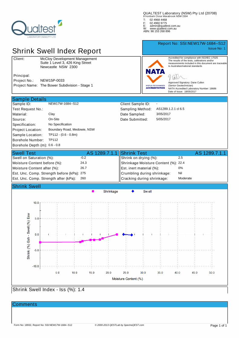
Sample DetailsSample ID: NEW17W-1684--S12 Client Sample ID: -
Test Request No.: Sampling Method: AS1289.1.2.1 cl 6.5
Material: Clay Date Sampled: 3/05/2017
Source: On-Site Date Submitted: 5/05/2017
Specification: No Specification
Project Location: Boundary Road, Medowie, NSW
Sample Location: TP112 - (0.6 - 0.8m)
Borehole Number: TP112
Borehole Depth (m): 0.6 - 0.8
Shrink Test AS 1289.7.1.1Shrink on drying (%): 2.5
Shrinkage Moisture Content (%): 22.4
Est. inert material (%): 0%
Crumbling during shrinkage: Nil
Cracking during shrinkage: Moderate
Swell Test AS 1289.7.1.1Swell on Saturation (%): -0.2
Moisture Content before (%): 24.3
Moisture Content after (%): 26.7
Est. Unc. Comp. Strength before (kPa): 275
Est. Unc. Comp. Strength after (kPa): 260
Shrink Swell
Shrink Swell Index - Iss (%): 1.4
Accredited for compliance with ISO/IEC 17025The results of the tests, calibrations and/ormeasurements included in this document are traceableto Australian/national standards
18/05/2017
Shrink Swell Index Report
Report No: SSI:NEW17W-1684--S12
Issue No: 1
Client:
Date of Issue:
NATA Accredited Laboratory Number: 18686
Approved Signatory: Dane Cullen
(Senior Geotechnician)Project Name: The Bower Subdivision - Stage 1
F: 02 4960 9775
QUALTEST Laboratory (NSW) Pty Ltd (20708)
T: 02 4968 4468
E: [email protected]: www.qualtest.com.auABN: 98 153 268 896
8 Ironbark Close Warabrook NSW 2304
Project No.: NEW15P-0033
Principal:
Suite 1 Level 3, 426 King StreetNewcastle NSW 2300
McCloy Development Management
Page 1 of 1Form No: 18932, Report No: SSI:NEW17W-1684--S12 © 2000-2013 QESTLab by SpectraQEST.com
Comments

Sample DetailsSample ID: NEW15W-2564--S16 Client Sample ID: -
Test Request No.: - Sampling Method: AS1289.1.2.1 cl 6.4b
Material: Clay Date Sampled: 24/11/2015
Source: On-Site Date Submitted: 25/11/2015
Specification: No Specification
Project Location: Medowie, NSW
Sample Location: TPQ39 - (0.4 - 0.6m)
Borehole Number: TPQ39
Borehole Depth (m): 0.4 to 0.6m
Shrink Test AS 1289.7.1.1Shrink on drying (%): 7.6
Shrinkage Moisture Content (%): 31.1
Est. inert material (%): 0
Crumbling during shrinkage: Nil
Cracking during shrinkage: Nil
Swell Test AS 1289.7.1.1Swell on Saturation (%): -0.4
Moisture Content before (%): 30.5
Moisture Content after (%): 36.2
Est. Unc. Comp. Strength before (kPa): 210
Est. Unc. Comp. Strength after (kPa): 150
Shrink Swell
Shrink Swell Index - Iss (%): 4.2
Accredited for compliance with ISO/IEC 17025The results of the tests, calibrations and/ormeasurements included in this document are traceableto Australian/national standards
2/12/2015
Shrink Swell Index Report
Report No: SSI:NEW15W-2564--S16
Issue No: 1
Client:
Date of Issue:
NATA Accredited Laboratory Number: 18686
Approved Signatory: Dane Cullen
(Senior Geotechnician)Project Name: Proposed Subdivision - Boundary Road, Medowie
F: 02 4960 9775
QUALTEST Laboratory (NSW) Pty Ltd (20708)
T: 02 4968 4468
E: [email protected]: www.qualtest.com.auABN: 98 153 268 896
8 Ironbark Close Warabrook NSW 2304
Project No.: NEW15P-0033
Principal:
Suite 1 Level 3, 426 King StreetNewcastle NSW 2300
McCloy Medowie Pty Ltd
Page 1 of 1Form No: 18932, Report No: SSI:NEW15W-2564--S16 © 2000-2013 QESTLab by SpectraQEST.com
Comments

Sample DetailsSample ID: NEW15W-2564--S17 Client Sample ID: -
Test Request No.: - Sampling Method: AS1289.1.2.1 cl 6.4b
Material: Clay Date Sampled: 24/11/2015
Source: On-Site Date Submitted: 25/11/2015
Specification: No Specification
Project Location: Medowie, NSW
Sample Location: TPQ40 - (0.3 - 0.45m)
Borehole Number: TPQ40
Borehole Depth (m): 0.3 to 0.45m
Shrink Test AS 1289.7.1.1Shrink on drying (%): 7.7
Shrinkage Moisture Content (%): 33.6
Est. inert material (%): 1
Crumbling during shrinkage: Nil
Cracking during shrinkage: MInor
Swell Test AS 1289.7.1.1Swell on Saturation (%): -0.2
Moisture Content before (%): 35.8
Moisture Content after (%): 38.2
Est. Unc. Comp. Strength before (kPa): 500
Est. Unc. Comp. Strength after (kPa): 230
Shrink Swell
Shrink Swell Index - Iss (%): 4.3
Accredited for compliance with ISO/IEC 17025The results of the tests, calibrations and/ormeasurements included in this document are traceableto Australian/national standards
2/12/2015
Shrink Swell Index Report
Report No: SSI:NEW15W-2564--S17
Issue No: 1
Client:
Date of Issue:
NATA Accredited Laboratory Number: 18686
Approved Signatory: Dane Cullen
(Senior Geotechnician)Project Name: Proposed Subdivision - Boundary Road, Medowie
F: 02 4960 9775
QUALTEST Laboratory (NSW) Pty Ltd (20708)
T: 02 4968 4468
E: [email protected]: www.qualtest.com.auABN: 98 153 268 896
8 Ironbark Close Warabrook NSW 2304
Project No.: NEW15P-0033
Principal:
Suite 1 Level 3, 426 King StreetNewcastle NSW 2300
McCloy Medowie Pty Ltd
Page 1 of 1Form No: 18932, Report No: SSI:NEW15W-2564--S17 © 2000-2013 QESTLab by SpectraQEST.com
Comments

Sample DetailsSample ID: NEW15W-2564--S18 Client Sample ID: -
Test Request No.: - Sampling Method: AS1289.1.2.1 cl 6.4b
Material: Clay Date Sampled: 24/11/2015
Source: On-Site Date Submitted: 25/11/2015
Specification: No Specification
Project Location: Medowie, NSW
Sample Location: TPQ41 - (0.35 - 0.50m)
Borehole Number: TPQ41
Borehole Depth (m): 0.35 to 0.50m
Shrink Test AS 1289.7.1.1Shrink on drying (%): 5.1
Shrinkage Moisture Content (%): 27.9
Est. inert material (%): 1
Crumbling during shrinkage: Nil
Cracking during shrinkage: Major
Swell Test AS 1289.7.1.1Swell on Saturation (%): -0.1
Moisture Content before (%): 24.9
Moisture Content after (%): 25.5
Est. Unc. Comp. Strength before (kPa): 400
Est. Unc. Comp. Strength after (kPa): 260
Shrink Swell
Shrink Swell Index - Iss (%): 2.8
Accredited for compliance with ISO/IEC 17025The results of the tests, calibrations and/ormeasurements included in this document are traceableto Australian/national standards
2/12/2015
Shrink Swell Index Report
Report No: SSI:NEW15W-2564--S18
Issue No: 1
Client:
Date of Issue:
NATA Accredited Laboratory Number: 18686
Approved Signatory: Dane Cullen
(Senior Geotechnician)Project Name: Proposed Subdivision - Boundary Road, Medowie
F: 02 4960 9775
QUALTEST Laboratory (NSW) Pty Ltd (20708)
T: 02 4968 4468
E: [email protected]: www.qualtest.com.auABN: 98 153 268 896
8 Ironbark Close Warabrook NSW 2304
Project No.: NEW15P-0033
Principal:
Suite 1 Level 3, 426 King StreetNewcastle NSW 2300
McCloy Medowie Pty Ltd
Page 1 of 1Form No: 18932, Report No: SSI:NEW15W-2564--S18 © 2000-2013 QESTLab by SpectraQEST.com
Comments

Sample DetailsSample ID: NEW15W-2564--S19 Client Sample ID: -
Test Request No.: - Sampling Method: AS1289.1.2.1 cl 6.4b
Material: Clay Date Sampled: 24/11/2015
Source: On-Site Date Submitted: 25/11/2015
Specification: No Specification
Project Location: Medowie, NSW
Sample Location: TPQ42 - (0.2 - 0.45m)
Borehole Number: TPQ42
Borehole Depth (m): 0.2 to 0.45m
Shrink Test AS 1289.7.1.1Shrink on drying (%): 9.6
Shrinkage Moisture Content (%): 38.8
Est. inert material (%): 1
Crumbling during shrinkage: Nil
Cracking during shrinkage: Minor
Swell Test AS 1289.7.1.1Swell on Saturation (%): -0.2
Moisture Content before (%): 39.6
Moisture Content after (%): 42.3
Est. Unc. Comp. Strength before (kPa): 200
Est. Unc. Comp. Strength after (kPa): 120
Shrink Swell
Shrink Swell Index - Iss (%): 5.3
Shrink Swell Index Report
Report No: SSI:NEW15W-2564--S19
Client:
Date of Issue:
Project Name: Proposed Subdivision - Boundary Road, Medowie
F: 02 4960 9775
QUALTEST Laboratory (NSW) Pty Ltd (20708)
T: 02 4968 4468
E: [email protected]: www.qualtest.com.auABN: 98 153 268 896
8 Ironbark Close Warabrook NSW 2304
Project No.: NEW15P-0033
Principal:
Suite 1 Level 3, 426 King StreetNewcastle NSW 2300
McCloy Medowie Pty Ltd
Page 1 of 1Form No: 18932, Report No: SSI:NEW15W-2564--S19 © 2000-2013 QESTLab by SpectraQEST.com
Comments

APPENDIX C:
CSIRO Sheet BTF 18
Foundation Maintenance and Footing
Performance: A Homeowner’s Guide
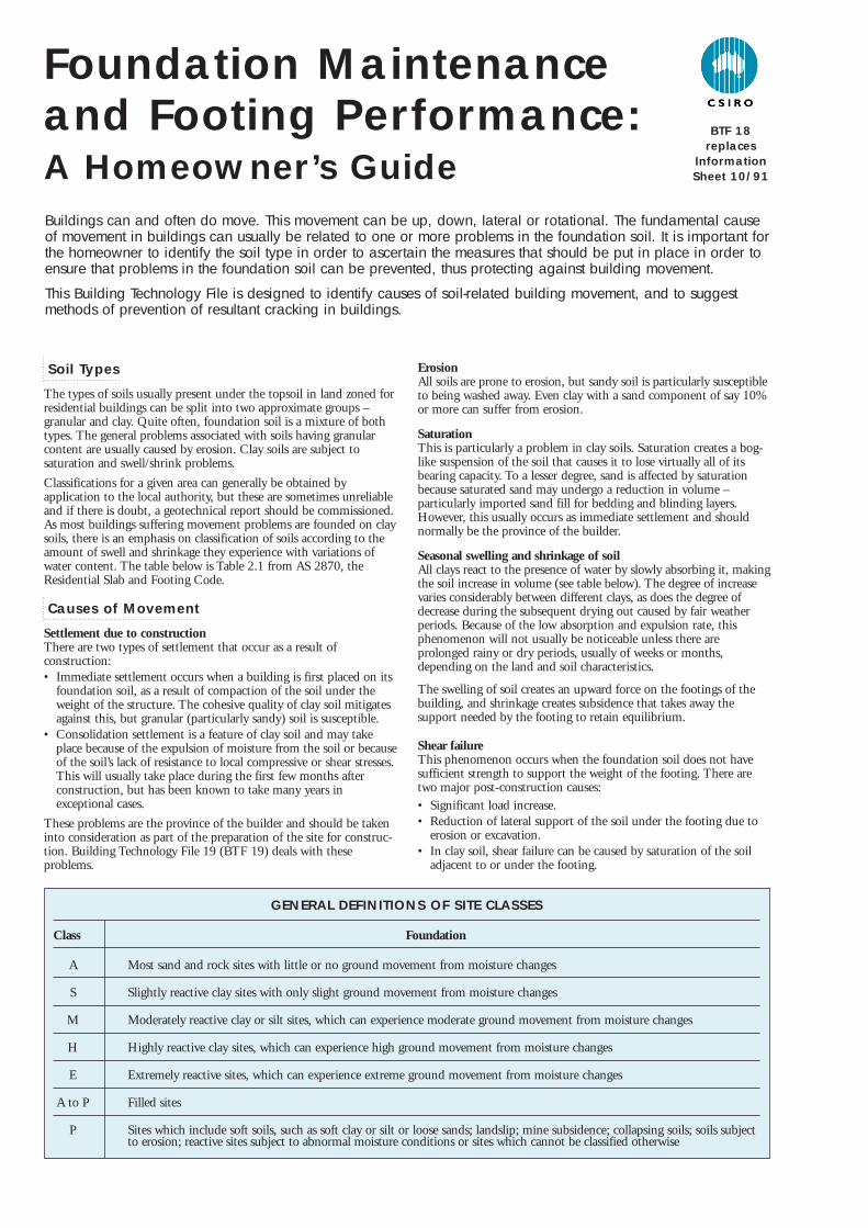
Soil Types
The types of soils usually present under the topsoil in land zoned forresidential buildings can be split into two approximate groups –granular and clay. Quite often, foundation soil is a mixture of bothtypes. The general problems associated with soils having granularcontent are usually caused by erosion. Clay soils are subject tosaturation and swell/shrink problems.
Classifications for a given area can generally be obtained byapplication to the local authority, but these are sometimes unreliableand if there is doubt, a geotechnical report should be commissioned.As most buildings suffering movement problems are founded on claysoils, there is an emphasis on classification of soils according to theamount of swell and shrinkage they experience with variations ofwater content. The table below is Table 2.1 from AS 2870, theResidential Slab and Footing Code.
Causes of Movement
Settlement due to constructionThere are two types of settlement that occur as a result ofconstruction:• Immediate settlement occurs when a building is first placed on its
foundation soil, as a result of compaction of the soil under theweight of the structure. The cohesive quality of clay soil mitigatesagainst this, but granular (particularly sandy) soil is susceptible.
• Consolidation settlement is a feature of clay soil and may takeplace because of the expulsion of moisture from the soil or becauseof the soil’s lack of resistance to local compressive or shear stresses.This will usually take place during the first few months afterconstruction, but has been known to take many years inexceptional cases.
These problems are the province of the builder and should be takeninto consideration as part of the preparation of the site for construc-tion. Building Technology File 19 (BTF 19) deals with theseproblems.
ErosionAll soils are prone to erosion, but sandy soil is particularly susceptibleto being washed away. Even clay with a sand component of say 10%or more can suffer from erosion.
SaturationThis is particularly a problem in clay soils. Saturation creates a bog-like suspension of the soil that causes it to lose virtually all of itsbearing capacity. To a lesser degree, sand is affected by saturationbecause saturated sand may undergo a reduction in volume –particularly imported sand fill for bedding and blinding layers.However, this usually occurs as immediate settlement and shouldnormally be the province of the builder.
Seasonal swelling and shrinkage of soilAll clays react to the presence of water by slowly absorbing it, makingthe soil increase in volume (see table below). The degree of increasevaries considerably between different clays, as does the degree ofdecrease during the subsequent drying out caused by fair weatherperiods. Because of the low absorption and expulsion rate, thisphenomenon will not usually be noticeable unless there areprolonged rainy or dry periods, usually of weeks or months,depending on the land and soil characteristics.
The swelling of soil creates an upward force on the footings of thebuilding, and shrinkage creates subsidence that takes away thesupport needed by the footing to retain equilibrium.
Shear failureThis phenomenon occurs when the foundation soil does not havesufficient strength to support the weight of the footing. There aretwo major post-construction causes:• Significant load increase.• Reduction of lateral support of the soil under the footing due to
erosion or excavation.• In clay soil, shear failure can be caused by saturation of the soil
adjacent to or under the footing.
Buildings can and often do move. This movement can be up, down, lateral or rotational. The fundamental causeof movement in buildings can usually be related to one or more problems in the foundation soil. It is important forthe homeowner to identify the soil type in order to ascertain the measures that should be put in place in order toensure that problems in the foundation soil can be prevented, thus protecting against building movement.
This Building Technology File is designed to identify causes of soil-related building movement, and to suggestmethods of prevention of resultant cracking in buildings.
Foundation Maintenanceand Footing Performance:A Homeowner’s Guide
GENERAL DEFINITIONS OF SITE CLASSES
Class Foundation
A Most sand and rock sites with little or no ground movement from moisture changes
S Slightly reactive clay sites with only slight ground movement from moisture changes
M Moderately reactive clay or silt sites, which can experience moderate ground movement from moisture changes
H Highly reactive clay sites, which can experience high ground movement from moisture changes
E Extremely reactive sites, which can experience extreme ground movement from moisture changes
A to P Filled sites
P Sites which include soft soils, such as soft clay or silt or loose sands; landslip; mine subsidence; collapsing soils; soils subject to erosion; reactive sites subject to abnormal moisture conditions or sites which cannot be classified otherwise
BTF 18replaces
InformationSheet 10/91

Tree root growthTrees and shrubs that are allowed to grow in the vicinity of footingscan cause foundation soil movement in two ways:
• Roots that grow under footings may increase in cross-sectionalsize, exerting upward pressure on footings.
• Roots in the vicinity of footings will absorb much of the moisturein the foundation soil, causing shrinkage or subsidence.
Unevenness of Movement
The types of ground movement described above usually occurunevenly throughout the building’s foundation soil. Settlement dueto construction tends to be uneven because of:
• Differing compaction of foundation soil prior to construction.• Differing moisture content of foundation soil prior to construction.
Movement due to non-construction causes is usually more unevenstill. Erosion can undermine a footing that traverses the flow or cancreate the conditions for shear failure by eroding soil adjacent to afooting that runs in the same direction as the flow.
Saturation of clay foundation soil may occur where subfloor wallscreate a dam that makes water pond. It can also occur wherever thereis a source of water near footings in clay soil. This leads to a severereduction in the strength of the soil which may create local shearfailure.
Seasonal swelling and shrinkage of clay soil affects the perimeter ofthe building first, then gradually spreads to the interior. The swellingprocess will usually begin at the uphill extreme of the building, or onthe weather side where the land is flat. Swelling gradually reaches theinterior soil as absorption continues. Shrinkage usually begins wherethe sun’s heat is greatest.
Effects of Uneven Soil Movement on Structures
Erosion and saturationErosion removes the support from under footings, tending to createsubsidence of the part of the structure under which it occurs.Brickwork walls will resist the stress created by this removal ofsupport by bridging the gap or cantilevering until the bricks or themortar bedding fail. Older masonry has little resistance. Evidence offailure varies according to circumstances and symptoms may include:
• Step cracking in the mortar beds in the body of the wall orabove/below openings such as doors or windows.
• Vertical cracking in the bricks (usually but not necessarily in linewith the vertical beds or perpends).
Isolated piers affected by erosion or saturation of foundations willeventually lose contact with the bearers they support and may tilt orfall over. The floors that have lost this support will become bouncy,sometimes rattling ornaments etc.
Seasonal swelling/shrinkage in claySwelling foundation soil due to rainy periods first lifts the mostexposed extremities of the footing system, then the remainder of theperimeter footings while gradually permeating inside the buildingfootprint to lift internal footings. This swelling first tends to create adish effect, because the external footings are pushed higher than theinternal ones.
The first noticeable symptom may be that the floor appears slightlydished. This is often accompanied by some doors binding on thefloor or the door head, together with some cracking of cornicemitres. In buildings with timber flooring supported by bearers andjoists, the floor can be bouncy. Externally there may be visibledishing of the hip or ridge lines.
As the moisture absorption process completes its journey to theinnermost areas of the building, the internal footings will rise. If thespread of moisture is roughly even, it may be that the symptoms willtemporarily disappear, but it is more likely that swelling will beuneven, creating a difference rather than a disappearance insymptoms. In buildings with timber flooring supported by bearersand joists, the isolated piers will rise more easily than the stripfootings or piers under walls, creating noticeable doming of flooring.
As the weather pattern changes and the soil begins to dry out, theexternal footings will be first affected, beginning with the locationswhere the sun’s effect is strongest. This has the effect of lowering theexternal footings. The doming is accentuated and cracking reducesor disappears where it occurred because of dishing, but other cracksopen up. The roof lines may become convex.
Doming and dishing are also affected by weather in other ways. Inareas where warm, wet summers and cooler dry winters prevail,water migration tends to be toward the interior and doming will beaccentuated, whereas where summers are dry and winters are coldand wet, migration tends to be toward the exterior and theunderlying propensity is toward dishing.
Movement caused by tree rootsIn general, growing roots will exert an upward pressure on footings,whereas soil subject to drying because of tree or shrub roots will tendto remove support from under footings by inducing shrinkage.
Complications caused by the structure itselfMost forces that the soil causes to be exerted on structures arevertical – i.e. either up or down. However, because these forces areseldom spread evenly around the footings, and because the buildingresists uneven movement because of its rigidity, forces are exertedfrom one part of the building to another. The net result of all theseforces is usually rotational. This resultant force often complicates thediagnosis because the visible symptoms do not simply reflect theoriginal cause. A common symptom is binding of doors on thevertical member of the frame.
Effects on full masonry structuresBrickwork will resist cracking where it can. It will attempt to spanareas that lose support because of subsided foundations or raisedpoints. It is therefore usual to see cracking at weak points, such asopenings for windows or doors.
In the event of construction settlement, cracking will usually remainunchanged after the process of settlement has ceased.
With local shear or erosion, cracking will usually continue to developuntil the original cause has been remedied, or until the subsidencehas completely neutralised the affected portion of footing and thestructure has stabilised on other footings that remain effective.
In the case of swell/shrink effects, the brickwork will in some casesreturn to its original position after completion of a cycle, however itis more likely that the rotational effect will not be exactly reversed,and it is also usual that brickwork will settle in its new position andwill resist the forces trying to return it to its original position. Thismeans that in a case where swelling takes place after constructionand cracking occurs, the cracking is likely to at least partly remainafter the shrink segment of the cycle is complete. Thus, each timethe cycle is repeated, the likelihood is that the cracking will becomewider until the sections of brickwork become virtually independent.
With repeated cycles, once the cracking is established, if there is noother complication, it is normal for the incidence of cracking tostabilise, as the building has the articulation it needs to cope withthe problem. This is by no means always the case, however, andmonitoring of cracks in walls and floors should always be treatedseriously.
Upheaval caused by growth of tree roots under footings is not asimple vertical shear stress. There is a tendency for the root to alsoexert lateral forces that attempt to separate sections of brickworkafter initial cracking has occurred.
Trees can cause shrinkage and damage

The normal structural arrangement is that the inner leaf of brick-work in the external walls and at least some of the internal walls(depending on the roof type) comprise the load-bearing structure onwhich any upper floors, ceilings and the roof are supported. In thesecases, it is internally visible cracking that should be the main focusof attention, however there are a few examples of dwellings whoseexternal leaf of masonry plays some supporting role, so this shouldbe checked if there is any doubt. In any case, externally visiblecracking is important as a guide to stresses on the structure generally,and it should also be remembered that the external walls must becapable of supporting themselves.
Effects on framed structuresTimber or steel framed buildings are less likely to exhibit crackingdue to swell/shrink than masonry buildings because of theirflexibility. Also, the doming/dishing effects tend to be lower becauseof the lighter weight of walls. The main risks to framed buildings areencountered because of the isolated pier footings used under walls.Where erosion or saturation cause a footing to fall away, this candouble the span which a wall must bridge. This additional stress cancreate cracking in wall linings, particularly where there is a weakpoint in the structure caused by a door or window opening. It is,however, unlikely that framed structures will be so stressed as to sufferserious damage without first exhibiting some or all of the abovesymptoms for a considerable period. The same warning period shouldapply in the case of upheaval. It should be noted, however, that whereframed buildings are supported by strip footings there is only one leafof brickwork and therefore the externally visible walls are thesupporting structure for the building. In this case, the subfloormasonry walls can be expected to behave as full brickwork walls.
Effects on brick veneer structuresBecause the load-bearing structure of a brick veneer building is theframe that makes up the interior leaf of the external walls plusperhaps the internal walls, depending on the type of roof, thebuilding can be expected to behave as a framed structure, except thatthe external masonry will behave in a similar way to the external leafof a full masonry structure.
Water Service and Drainage
Where a water service pipe, a sewer or stormwater drainage pipe is inthe vicinity of a building, a water leak can cause erosion, swelling orsaturation of susceptible soil. Even a minuscule leak can be enoughto saturate a clay foundation. A leaking tap near a building can havethe same effect. In addition, trenches containing pipes can becomewatercourses even though backfilled, particularly where brokenrubble is used as fill. Water that runs along these trenches can beresponsible for serious erosion, interstrata seepage into subfloor areasand saturation.
Pipe leakage and trench water flows also encourage tree and shrubroots to the source of water, complicating and exacerbating theproblem.Poor roof plumbing can result in large volumes of rainwater beingconcentrated in a small area of soil:
• Incorrect falls in roof guttering may result in overflows, as maygutters blocked with leaves etc.
• Corroded guttering or downpipes can spill water to ground.• Downpipes not positively connected to a proper stormwater
collection system will direct a concentration of water to soil that isdirectly adjacent to footings, sometimes causing large-scaleproblems such as erosion, saturation and migration of water underthe building.
Seriousness of Cracking
In general, most cracking found in masonry walls is a cosmeticnuisance only and can be kept in repair or even ignored. The tablebelow is a reproduction of Table C1 of AS 2870.
AS 2870 also publishes figures relating to cracking in concrete floors,however because wall cracking will usually reach the critical pointsignificantly earlier than cracking in slabs, this table is notreproduced here.
Prevention/Cure
PlumbingWhere building movement is caused by water service, roof plumbing,sewer or stormwater failure, the remedy is to repair the problem. It is prudent, however, to consider also rerouting pipes away fromthe building where possible, and relocating taps to positions whereany leakage will not direct water to the building vicinity. Even wheregully traps are present, there is sometimes sufficient spill to createerosion or saturation, particularly in modern installations usingsmaller diameter PVC fixtures. Indeed, some gully traps are notsituated directly under the taps that are installed to charge them,with the result that water from the tap may enter the backfilledtrench that houses the sewer piping. If the trench has been poorlybackfilled, the water will either pond or flow along the bottom ofthe trench. As these trenches usually run alongside the footings andcan be at a similar depth, it is not hard to see how any water that isthus directed into a trench can easily affect the foundation’s ability tosupport footings or even gain entry to the subfloor area.
Ground drainageIn all soils there is the capacity for water to travel on the surface andbelow it. Surface water flows can be established by inspection duringand after heavy or prolonged rain. If necessary, a grated drain systemconnected to the stormwater collection system is usually an easysolution.
It is, however, sometimes necessary when attempting to preventwater migration that testing be carried out to establish watertableheight and subsoil water flows. This subject is referred to in BTF 19and may properly be regarded as an area for an expert consultant.
Protection of the building perimeterIt is essential to remember that the soil that affects footings extendswell beyond the actual building line. Watering of garden plants,shrubs and trees causes some of the most serious water problems.
For this reason, particularly where problems exist or are likely tooccur, it is recommended that an apron of paving be installedaround as much of the building perimeter as necessary. This paving
CLASSIFICATION OF DAMAGE WITH REFERENCE TO WALLS
Description of typical damage and required repair Approximate crack width Damagelimit (see Note 3) category
Hairline cracks <0.1 mm 0
Fine cracks which do not need repair <1 mm 1
Cracks noticeable but easily filled. Doors and windows stick slightly <5 mm 2
Cracks can be repaired and possibly a small amount of wall will need 5–15 mm (or a number of cracks 3to be replaced. Doors and windows stick. Service pipes can fracture. 3 mm or more in one group)Weathertightness often impaired
Extensive repair work involving breaking-out and replacing sections of walls, 15–25 mm but also depend 4especially over doors and windows. Window and door frames distort. Walls lean on number of cracksor bulge noticeably, some loss of bearing in beams. Service pipes disrupted

should extend outwards a minimum of 900 mm (more in highlyreactive soil) and should have a minimum fall away from thebuilding of 1:60. The finished paving should be no less than 100mm below brick vent bases.
It is prudent to relocate drainage pipes away from this paving, ifpossible, to avoid complications from future leakage. If this is notpractical, earthenware pipes should be replaced by PVC andbackfilling should be of the same soil type as the surrounding soiland compacted to the same density.
Except in areas where freezing of water is an issue, it is wise toremove taps in the building area and relocate them well away fromthe building – preferably not uphill from it (see BTF 19).
It may be desirable to install a grated drain at the outside edge of thepaving on the uphill side of the building. If subsoil drainage isneeded this can be installed under the surface drain.
CondensationIn buildings with a subfloor void such as where bearers and joistssupport flooring, insufficient ventilation creates ideal conditions forcondensation, particularly where there is little clearance between thefloor and the ground. Condensation adds to the moisture alreadypresent in the subfloor and significantly slows the process of dryingout. Installation of an adequate subfloor ventilation system, eithernatural or mechanical, is desirable.
Warning: Although this Building Technology File deals withcracking in buildings, it should be said that subfloor moisture canresult in the development of other problems, notably:
• Water that is transmitted into masonry, metal or timber buildingelements causes damage and/or decay to those elements.
• High subfloor humidity and moisture content create an idealenvironment for various pests, including termites and spiders.
• Where high moisture levels are transmitted to the flooring andwalls, an increase in the dust mite count can ensue within theliving areas. Dust mites, as well as dampness in general, can be ahealth hazard to inhabitants, particularly those who areabnormally susceptible to respiratory ailments.
The gardenThe ideal vegetation layout is to have lawn or plants that requireonly light watering immediately adjacent to the drainage or pavingedge, then more demanding plants, shrubs and trees spread out inthat order.
Overwatering due to misuse of automatic watering systems is acommon cause of saturation and water migration under footings. Ifit is necessary to use these systems, it is important to remove gardenbeds to a completely safe distance from buildings.
Existing treesWhere a tree is causing a problem of soil drying or there is theexistence or threat of upheaval of footings, if the offending roots aresubsidiary and their removal will not significantly damage the tree,they should be severed and a concrete or metal barrier placedvertically in the soil to prevent future root growth in the direction ofthe building. If it is not possible to remove the relevant rootswithout damage to the tree, an application to remove the tree shouldbe made to the local authority. A prudent plan is to transplant likelyoffenders before they become a problem.
Information on trees, plants and shrubsState departments overseeing agriculture can give informationregarding root patterns, volume of water needed and safe distancefrom buildings of most species. Botanic gardens are also sources ofinformation. For information on plant roots and drains, see BuildingTechnology File 17.
ExcavationExcavation around footings must be properly engineered. Soilsupporting footings can only be safely excavated at an angle thatallows the soil under the footing to remain stable. This angle iscalled the angle of repose (or friction) and varies significantlybetween soil types and conditions. Removal of soil within the angleof repose will cause subsidence.
Remediation
Where erosion has occurred that has washed away soil adjacent tofootings, soil of the same classification should be introduced andcompacted to the same density. Where footings have beenundermined, augmentation or other specialist work may be required.Remediation of footings and foundations is generally the realm of aspecialist consultant.
Where isolated footings rise and fall because of swell/shrink effect,the homeowner may be tempted to alleviate floor bounce by fillingthe gap that has appeared between the bearer and the pier withblocking. The danger here is that when the next swell segment of thecycle occurs, the extra blocking will push the floor up into anaccentuated dome and may also cause local shear failure in the soil.If it is necessary to use blocking, it should be by a pair of finewedges and monitoring should be carried out fortnightly.
This BTF was prepared by John Lewer FAIB, MIAMA, Partner,Construction Diagnosis.
The information in this and other issues in the series was derived from various sources and was believed to be correct when published.
The information is advisory. It is provided in good faith and not claimed to be an exhaustive treatment of the relevant subject.
Further professional advice needs to be obtained before taking any action based on the information provided.
Distributed by
CSIRO PUBL ISHING PO Box 1139, Collingwood 3066, AustraliaFreecall 1800 645 051 Tel (03) 9662 7666 Fax (03) 9662 7555 www.publish.csiro.au
Email: [email protected]
© CSIRO 2003. Unauthorised copying of this Building Technology file is prohibited
Gardens for a reactive site