Embed Size (px)
Citation preview

MEC
Design Report by :- Ir. Philip Goh (B.Sc, MIEM, P.Eng, MICE, C.Eng) 70Final Design Report.Doc70Final Design Report.Doc/page 1
PROPOSED KINDA ROAD 1 NORTH, BINTULU
FOR
BINTULU DEVELOPMENT AUTHORITY
FINAL DESIGN REPORT
Prepared by:- Ir. Philip Goh (B.Sc, MIEC, C.Eng, MIEM, P.Eng)
Chief Civil & Structural Engineer 1 July 2009
Consulting Engineer M.E.C. Engineering Technologies Sdn Bhd
Licenced UPK, MOF, BEM

MEC
Design Report by :- Ir. Philip Goh (B.Sc, MIEM, P.Eng, MICE, C.Eng) 70Final Design Report.Doc70Final Design Report.Doc/page 2
TABLE OF CONTENTS FOR
DESIGN CRITERIA ROAD 1 NORTH, INFRASTRUCTURE WORKS
1. INTRODUCTION 2. PROJECT BRIEF
3. SPECIAL CONSTRAINTS
4. ROADS
5. DRAINAGE
6. SEWERAGE
7. WATER SUPPLY
8. ROAD 1 BRIDGE/BPA JUNCTION
9. SMDS PIPELINES
10. SURVEY
11. SOIL
12. BRIDGE
13. DRAWINGS
14. TENDER & COSTING

MEC
Design Report by :- Ir. Philip Goh (B.Sc, MIEM, P.Eng, MICE, C.Eng) 70Final Design Report.Doc70Final Design Report.Doc/page 3
1. INTRODUCTION
This is the Final Report of the “Proposed Extension of Infrastructural Services Of Road 1 North, for Kidurong Industrial Area (Kinda), Tg.Kidurong, Bintulu (Road 1 North)”. This Report will covers the Design Criteria used for the Project.
The reader is referred to separate documents related or specified in this Report for “Drawings”, “Tender Documents”, “Soil Investigation Report”, “Survey Drawings”. These separate documents are not included here.
2. PROJECT BRIEF
The design works was initiated sometime in April 2005 as part of the Kidurong Industrial Area development infrastructure. It is part of Road 1 of KINDA, consisting of a 45m existing road reserve, with about 1250m length from the existing Road 2 in the south junction at Bintulu Adhesive and extending northwards to join up with the existing Bintulu Port Authority Road, and to finally link up to the existing Tg. Kidurong Main Road. This road will act as the Coastal Link Road to serve the future alternative road linking from the south Kidurong Residential Estate to Bintulu Deepwater Port, the Kidurong Industrial Area, and the Tg Kidurong road, forming a vital alternative and shorter route for vehicles to & from the north-south. This future 45m width dual carriage road will no doubt forms a major arterial road for a vast residential, commercial and industrial activities, in the Kidurong Area. The short link of 1250m will form the vital finishing stretch for the Kidurong Road Junction, served by a traffic light system. This short North End is vital for the Coastal Link Road to work effectively as planned. The Works consist of two distinct portions: The Roadworks & the Bridgeworks. The bridge is required to span over existing SMDS & Petronas Pipelines. The following were approximate time-line for the works :-
• Project Initiation - April 2005 • Topo & Boundary Survey - Nov 2005 (Perunding Survey TS costs $30,229.50) • Soil Investigations - Feb 2006 (Fieldgeo Sdn Bhd costs $21,958.40) • Prelim Design 1 - July 2006 • Final Design 2 - Oct 2006 • Tender - Jan 2009 • Tender Evaluation - June 2009


MEC
Design Report by :- Ir. Philip Goh (B.Sc, MIEM, P.Eng, MICE, C.Eng) 70Final Design Report.Doc70Final Design Report.Doc/page 4
3. SPECIAL CONSTRAINTS
The design and construction of the Roadworks are straight forward. The Bridgeworks however poise a unique situation giving rise to several difficult problems; as it is required to cross over a very sensitive, risky and critically important existing Shell MDS Pipelines while at the same time serve as an intersection for the only access to Bintulu Deepwater Port, and constrained further by an existing height limitations above and below the bridge. An existing concrete bridge creates a further problem for integration of propose new works to existing road, making upgrade potentially costly and difficult.
Coupled with the above, the Financial Constraint of $5 million makes design of such works difficult. These constraints and solutions will be highlighted further in the details sections below.
4. ROADS
Road Reserve The Road Reserve is 45M and is already an existing reserve stretching from the Sg Plan Besar in the south to intersection with Tg Kidurong Road. The Carriageways will be sited within the standard cross-section, and such the horizontal alignment is already defined by BDA. Road Cross-Sections The Standard Road Cross-Section for Dual Carriageway adopted by BDA for the Kidurong Industrial Area is being used, modified to incorporate the recent approved State Planning Authority Standard which is also being adopted by all Local Authorities and Councils for Council Roads. This will supercede JKR standards.
The present design provides for a single carriageway. However as the road approaches the existing Bintulu Port Junction, it opens up into a Dual Carriageway to merge with the existing Port Bridge & Road which is a dual carriageway up to traffic light junction with Tg Kidurong Road. In the future when traffic is intensified, particularly when the Port Road is closed and all heavy commercial vehicles will use the road to enter the Deep Water Port, upgrade of this Road 1 into fully Dual carriageway is critical to ensure efficient traffic system.
Geometric Standards The 45m Road System forms the Arterial Coastal Road linking zoned clusters of development serving residential, commercial and industrial areas, all within an Urban & Rural setting. For the stretch of Road from Sg Plan Besar and up to the junction with Kidurong road, it serves the Kinda area which is an open Industrial Estate and the all busy and important Bintulu Deep Water port. The design for this stretch of road would be classified for Urban Standard as follows :-

MEC
Design Report by :- Ir. Philip Goh (B.Sc, MIEM, P.Eng, MICE, C.Eng) 70Final Design Report.Doc70Final Design Report.Doc/page 5
Road Reserve 45M Road Classification Urban Setting – U4, Area II Design Speed 60 km/hr Carriageway Single, 2 x 3.65m (7.3m) Marginal strip : Hard 0 Motor-Cycle Lane 1.8m Conc Footpath 1.2m (one side) Median : Grass 9m (normal) Medium : min 1m (junctions/bridge) Stopping Sight Distance 85m Passing Site Distance 450m Cross Fall Pavement 2.5% (1:40) Cross Fall Shoulder :hard 4% (1:25) Cross Fall shoulder: grass 5% (1:20) Vertical Crest K 15 Vertical Sag K 15 Superelevation (max) 6% Min Spiral Length 35m Max Grade 5% Min Radius 150m
Every effort will be made to comply with the above criteria, however some reduction of standards may occur due or site constraints, and these occur, additional precautions and designs will be incorporated to ensure safety for traffic. Pavement Design Road bituminous structural pavement generally consist of a surface course (wearing course + binder course), road-base and sub-base in varying thicknesses. Structural pavement design is based on “Manual on Pavement Design – by JKR 5/85” and its predecessor Road Note 29 where applicable. It is to be noted that Road Note 29 have provisions for Industrial Pavements where substantially specialized commercial vehicles would be the better design criteria compared to the general public road usage of mixed commercial vehicles. This is mainly because Road 1 serves the only access for the Bintulu Deep Water Port and all categories of commercial vehicles should be used. The original design did not account for substantial specialized commercial vehicles as the access for substantial commercial vehicles to Port is still considered via the existing Port access near to the proposed new bridge. However, should the Port access be closed, then the design criteris should be modified and road upgraded to suit the more specialized commercial vehicles.
Life Span The method of design is based on the principle of the damaging effect of cumulative number of “equivalent standard axles” of 8.2 tonne, passing over the pavement during it’s design life. It is usual for flexible pavement to be designed for a 20 year life span, however, for this stretch of road which would undergo continuous upgrade, a life span of 10 years is used.

MEC
Design Report by :- Ir. Philip Goh (B.Sc, MIEM, P.Eng, MICE, C.Eng) 70Final Design Report.Doc70Final Design Report.Doc/page 6
Traffic Inorder to estimate the equivalent number of standard axles for design purposes, information about the distribution of actual axle loads on commercial vehicles is needed. At this stage for this short stretch of road, no data on traffic volumes are available, and as such it is not possible to estimate the cumulative number of standard axles, however, it is reasonable to assume an equivalent value of 1 x 10⁶ CBR The standard method of design depends on the CBR values of the subgrade, which can varry depending on the type of soils and the quality of compaction. For normal design purpose, a minimum of 5% is assumed, which must always be exceeded during construction stage.
Thicknesses Based on the above criteria, the design gives approximate values as follows:- Surfacings = 50mm Road Base = 250mm Sub Base = 225mm Total = 425mm However the BDA/KINDA area had used successfully a pavement composition which will be duplicated in this stretch as follows :-
Surfacings = 100mm (binder course=60mm initial, wearing course =40mm future) Road Base = 125mm Sub Base = 300mm Total = 525mm (initial thickness = 485mm)
Road Markings Continuous 150mm wide edge markings will be provided on each side of the carriageway, with intermittent 3m mark at 6m spacing centerline markings. Thermoplastic markings is to be used as permanent if complete surface sealing is carried out. However where the road surface is intended to be sealed or upgraded at a future date, use of the cheaper road paint is to be used. Road Kerbs Concrete Road kerbs are used mainly to protect pavement edges and grass shoulders. BDA standard road kerbs are to be used at medians and at junctions and slip roads. Appropriate drainage openings will be provided for pavement surface runoff. However, due to cost savings and possible upgrading in future, kerbs are not used except as median at approaches to bridge.
MEC
Design Report by :- Ir. Philip Goh (B.Sc, MIEM, P.Eng, MICE, C.Eng) 70Final Design Report.Doc70Final Design Report.Doc/page 7
Traffic Signs Standard Traffic signs will be used as appropriate.
Guard Rails Guard Rails are provided where it would be considered particularly dangerous for vehicles to leave the carriageways. Such locations include :-
• On embankments of height 3m or greater. • On embankments where there is a river, road, or buildings, exposed services &
structures at the foot of the slope. • On outside of curved embankments where the radius is less than 125m for height
between 3m or greater. • On approaches to structures. • On approaches to bridges. • Where required for protection of services by roadsides.
Street Lightings Locations of Street Lightings will be specified in the design based on the BDA Standard Cross Sections. However, exact positions, intensity and locations will be determined by the relevant agency and construction be made in the future when traffic demand night lightings. To avoid opening of sealed carriageways thereby damaging pavements and markings, and creating weaknesses in the structure and unsightly repairs, cross ductile iron pipes would be prelaid and buried at selected locations, mainly at junctions, these should be ideally decided by the relevant agency.
5. DRAINAGE
Type of Drains Concrete U drains will be used as road side drains. To allow for better hydraulic properties at low flows particularly during drier periods, the bottom invert will be chamfered with concrete precast half-round channel or moulded into shape with mass concrete. The size of concrete drains will depend on catchment with a minimum of 450mm width and 450mm width to ensure ease of maintenance. Trapezoidal Earth Drains will be used in areas where concrete U drains are not practical due site conditions. Drains are generally sized to cater for surface runoffs from upper catchment based on the fully developed land usage. A minimum gradient to provide self cleaning velocity of 0.9m/sec at full flow is normally provided for based on a rainfall return period of 1:2 years, and checked for damages resulting from a storm of 1:50 years. However if the road profile is generally flat, or outfall invert not achievable or being easily clogged, such cleansing velocity is not achievable and as such design is based only on natural flow due to tidal effects, and periodic desilting would be required to maintain flood free environment.

MEC
Design Report by :- Ir. Philip Goh (B.Sc, MIEM, P.Eng, MICE, C.Eng) 70Final Design Report.Doc70Final Design Report.Doc/page 8
For all drains a minimum practical gradient will be 1:1000. Maximum gradient would be such that the maximum velocity at full flow will not exceed 3m/sec. A free board of at least 300mm would be provided for all drains. The structural design of concrete U drains will be based on the vertical side wall retaining earth & water on both sides. Vehicular and higher fill embankment is simulated by assuming a 1m height earth surcharge. The rebars are designed to have a nominal cover of 20mm and on the earth side of the vertical wall, although in construction the rebars are usually located at mid-point. A minimum thickness of 100mm is used as a practical width. Use of weep holes would be avoided for shallow drains & sandy conditions as these normally are poorly constructed and would cause inflow of water into the soil thereby causing erosion and soil weakness.
Estimation of Runoff The Modified Rational method is being used which gives catchment runoff formula as follows :- Q= CsCiA Where, Q = peak discharge in cubic feet/sec for a return period of T years i = rainfall intensity in inches/hr, equal to the Time of Concentration (Tc) A = catchment in Acres C = runoff coefficient Cs = storage coefficient The Storage Coefficient is given by: Cs = 2Tc / (2Tc + Td) Where Tc = To + Td To=overland flow time in minutes Td=drain flow time in minutes
Sizing of Drains All roadside drains are sized based on the following criteria:- Flow capacity with a minimum of 300mm freeboard, with 1:2 rainfall return period Flow velocity at 0.9m/s min to 3m/s max (where possible) For Earth Drains, flow velocity shall be within the range of 0.6m/s to a max of 2.3m/s. A minimum of 450mm width x450mm depth for concrete drain, and 1500mm width x varying depth based on 1:1 side slope, for trapezoidal grass lined earth drains. The Manning’s Open Channel flow formula will be used as follows :- Q = (1.49 A R2/3 S1/2)/n Where Q = flow in ft/sec n = manning’s roughness coefficient A = Area in ft2

MEC
Design Report by :- Ir. Philip Goh (B.Sc, MIEM, P.Eng, MICE, C.Eng) 70Final Design Report.Doc70Final Design Report.Doc/page 9
R = Hydraulic Radius in ft S = Slope factor, ft/ft For Concrete Drains, n=0.015 For Culverts, n=0.013 For Earth Drains, n=0.035
Culverts Box culverts are used mainly due to its better hydraulic capacity with respect to height openings. Hydraulic capacity are sized similar to concrete drains. The structure is designed as a rectangular box with all edges fixed.
6. SEWERAGE
Sewer Pipes had already been provided in an earlier works for most of the developed areas, so no provision is made in this current project. For individual lots, use of septic tank is to implemented until such time when the areas are fully developed after which additional sewer lines can be laid.
7. WATER SUPPLY
There is no immediate need for water mains along this stretch of road. However, should the need arise water mains & fire hydrants can be laid along the road verge at the position as in the BDA Standard Road Cross Sections.
8. ROAD 1 BRIDGE/PORT JUNCTION
Existing Port Road The existing Bintulu Deep Water Port access road from Tg Kidurong Road is a Dual Carriageway width pavement. The intersection with Tg Kidurong is via traffic light system. A concrete bridge spans the original Sg Plan Besar which had been diverted to allow for land reclamation for the Industrial Estate development. This diversion resulted in the existing bridge being redundant as only minor surface runoff remains.
The existing Port Road is a vital access to and from Port, for commercial vehicles. The Port serves Bintulu Township and is the gate way for deep water port facilities, and as such is a very busy high traffic road. The positioning of the bridge is such that it forms a part of the Junction with Bintulu Port Access road. Discussions had been made between BPA and the Consultant during design stage. The BPA does not object to the Road 1/BPA Road Junction including repaving and regrading, as long as traffic is maintained to and from Port. The main criteria of this junction design are as follows :-
• to maintain major commercial traffic to & from Port towards Tg Kidurong Road • to provide traffic North-South for mainly Public Type vehicles.

MEC
Design Report by :- Ir. Philip Goh (B.Sc, MIEM, P.Eng, MICE, C.Eng) 70Final Design Report.Doc70Final Design Report.Doc/page 10
• to provide commercial type traffic left turning from Port and right turning from South • to ensure limitation of bridge deck & beam soffit levels. • to ensure limitation of top deck level of existing Port Bridge
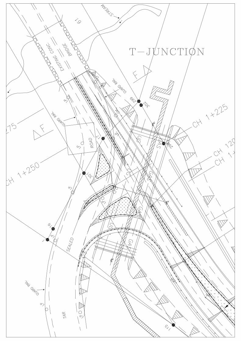
Several alternatives of junction design had been reviewed by BDA and Consultant outlined as follows:- T-Junction A T-junction for Port road was considered during design stage. This provides for maximum mobility of vehicles in all directions via traffic lights and is ideal for all intersections. This is in compliance with BPA requirements to maintain this junction opened all directional traffic. However, this require that much wider space to be provided and this also resulted in a bigger bridge area with some redundancies, which is not cost-efficient, at about RM 6.3million. Refer Drawing in Appendix A
Y-Junction This is not an ideal junction and does not provide maximum mobility in all directions. For vehicles to and from Port/Kidurong Main Road, vehicle flow will be smooth. However for vehicles right turn from Port and left turn from Kinda South, the acute angle of turn makes movement dangerous and difficult particularly for longer or trailer type vehicles.
The right turn from Port to Kinda South is particular dangerous and problematic. This has major impact on the design of bridge parapet, bearing and foundations as they will need to account for high direct impact, traction, and braking forces. The cost for this type is at about RM 3.3 million.
The Y-Junction is adopted for Tender.
9. SMDS PIPELINES
The existing SMDS & Petronas pipelines is sited within the 20m Energy Corridor which is a BDA allocated Reserve. The SMDS pipelines consist of 4 nos 350mm dia pipes at about 1m above ground, and many more pipes and services including electrical cables and instrumentations buried at about 1.5m below ground. One or two Petronas pipeline is also located next to SMDS pipelines. These Pipelines and Services occupy about 14m width of the Energy Corridor.
According to Shell MDS, these pipelines and their instrumentations are “alife 24 hrs” and are very sensitive to vibrations or movement & settlements, and require regular inspections and maintenance. Any damage or shutdown cannot be tolerated and would cause dramatic consequences to the SMDS Plant & Operations. SMDS however are not able to provide any vibrations, movement or settlement criteria other than saying that the parameters should be “zero”. The Consultant have extensive dialogue with SMDS on the possible crossings for the Pipelines and the following were considered :-
• covering up with earth. • constructing an RC slab over the exposed pipelines, similar to a “cross-over” or “culvert”

MEC
Design Report by :- Ir. Philip Goh (B.Sc, MIEM, P.Eng, MICE, C.Eng) 70Final Design Report.Doc70Final Design Report.Doc/page 11
• relocating the pipelines • enclosing the pipelines similar to the under-grounding at Tg Kidurong Road. • bridge crossing.
The options (a) - (d) were eliminated as the Pipelines require regular maintenance, inspection, and the buried portions cannot be subjected to permanent loadings & settlement, constraints as highlighted in the section on SMDS PIPELINES.
A bridge crossing is chosen as the only solution, which must spans the full width of the Pipelines and buried services, about 14m width. These parameters result in major design criteria being adopted for the bridgeworks outlined as follows :-
• Ground Vibration = zero (undetectable) • Ground Movement/Settlement = zero (undetectable) • Maintenance Space above pipelines = required for access/repairs/servicing • Damage to Pipelines/Services = not permitted • Temporary Plant Shutdown = not permitted
To comply with the SMDS parameters, the bridgeworks are designed as follows :-
• Abutment/Pier Offset from edge of Services = 3m min • Bridge Soffit Clearance to top of pipes = 450 mm (min), internally 1.8m min • Foundation Piling = small diameter bored piles, 600mm • Construction Safety/Protection = critical/joint supervision/smds QA/QC • Parapet/Approaches Structure = enhanced • Operational Safety = enhanced
10. SURVEY
Topographical survey was carried out by “Perunding Survei TS” sometime in Sept 2005, at a cost of RM30,229.50. Works include identification of the surface existing SMDS & Petronas Pipelines, electrical cables, and lightings, existing Port Road, and Junction with Kidurong Road. The survey also identified all existing structures and roads, drains, culverts within the Road 1 road reserve, up to junction with Road 2 near Bintulu Adhesive. A ground level exposed Petronas Pipeline 200∅ is found crossing Road 1 (at Junction with Road 2) and along Road 2 leading to serve “Astral”. This will need reinstallation to be buried when Road 1 is upgraded to dual carriageway. An exposed Pump House is found to be within the Road 1 Reserve, which will require cover up in future when pavement widening occurs An existing bridge constructed by Bintulu Port was identified. This bridge crosses the previous Sg Plan Besar, which is a major river flowing through Kinda Area. This river had been diverted into Sg Sebatang as part of Kinda development which had involved reclaimation of the diverted portion of Sg Plan Besar. The existing Port Bridge is noe redundant and serves only minor surface runoff from Kinda Area an part Kidurong Area.


MEC
Design Report by :- Ir. Philip Goh (B.Sc, MIEM, P.Eng, MICE, C.Eng) 70Final Design Report.Doc70Final Design Report.Doc/page 12
The survey indicate that the level at Port Road/Kidurong Road Junction is at about +9.5M, and the bridge about +8.2M and slope downwards into Port Road at about +7.7M. The areas around Road 1 and SMDS Pipelines varies and about +5.5M Refer to Survey Drawings as in Drawing Section
11. SOIL
Soil Investigations was carried out sometime in June 2006 by “Fieldgeo Sdn Bhd” a soil engineering contractor. A total of 4 boreholes were carried out within the proposed bridge foundation areas and the fifth borehole was carried out along the Road 1 approach road area. These 4 boreholes were positioned near the proposed foundation for the new shorter bridge providing T-junction. However, the Y-junction had been selected for final design & tender whose foundations are not as located. This would not significantly affect the foundation design other than the depth of rock will vary affecting final depth quantities and thus costs. The profile is typically stratified with loose to dense sands, stiff clayey silts and laminated rock, without any uniform consistency, as typical for areas around rivers and beaches. The SPT for substantial depth range from a low of 8 in loose sand to about 20 in medium stiff clays or silts, while some layers of dense sands and very stiff clayey silts gives SPT average of about 30. Dense area of shale/sandstone begins at about -26M, with hard sandstone rock at about -30M. The sandstone at BH4 is graded at Grade II/III, lab tested at about 47MPa compressive strength. Water level is also high and appears to vary, indicating effects of underground water movement, which is common in a sandy stratified soil profile and at river environment. Sulphates and chlorides are detected. The soil profile is generally good, and there are no swampy, peaty or soft soils, and as such foundations using pad footings, piles, or embankment fill are all possible with normal engineering design criteria. No surcharge is required for any embankment other than accounting for the normal short & long term settlements of imported soil and the underlying strata. Refer to Soil Report by Fieldgeo Sdn Bhd, and the Drawings
12 BRIDGE
The bridge is designed to cross SMDS Pipelines and the Energy Corridor. The operating conditions for the existing services determines the design of the bridge. Superstructure Since a Y-Junction is adopted as the most economical solution for the existing Road 1/BPA Junction, a simple span, using standard ‘I’ pre-stressed beams with reinforced concrete deck is chosen. Based on the need for working space and keeping an agreeable distance offset from SMDS & Petronas outermost underground services and to comply with SMDS criteria, Based on Survey by Licenced Surveyor the Petronas Gas Pipe and SMDS is unidentified on survey plan. On the south side, one or two 200∅ runs underground parallel to the SMDS pipeline, offset about 1.5m for the edge of SMDS Services. Since Petronas pipe is Steel Pipe carrying natural gas, the strength of steel pipe is very high and can take lots of deformation and stresses. This means the piles and abutment of the bridge can be as close as possible, a 1.90m is selected. This would still imply that the SMDS buried outermost service location is about 1.90+1.50=3.40, could be less.

MEC
Design Report by :- Ir. Philip Goh (B.Sc, MIEM, P.Eng, MICE, C.Eng) 70Final Design Report.Doc70Final Design Report.Doc/page 13
Towards the north side however, the surveyor identified the SMDS outermost underground services, which is sensitive to damage. Here we have allocated an offset of 3.45m. Note that these are approximate locations as SMDS themselves cannot identify the exact underground locations. Before construction begins, SMDS themselves will need to open up the trench physically and identify without doubt the exact locations for the full stretch of the bridge width, as we cannot be responsible for stray or offset cables and piles underground. Based on the above a minimum offset, which generally complies with SMDS minimum of 3.5m, that orthogonal distance is 20.70m while the skewed bridge span is 28.10m. Due to the length of the beam, a post-tensioned beam, to be constructed on site is selected. This will open up fair competition between contractors who can opt for pre-tensioned beams from specialized beam manufacturers in kuching, provided they are able to give competitive pricing on transportation. Abutment The abutment at both ends is kept as small and as high above as possible, to minimize excessive excavation. The design of the abutment is a straight forward foundation/pilecap design, where all loads from the bridge is transferred through the abutment and into the piles. Due to excessive skewed angle and the large incoming traction and impact forces from BPA traffic, consisting of heavy commercial vehicles, a double row of piles will be needed to take all stresses, including overturning stability in all direction. The abutment with the fixed bearing will be analysed differently from one with pinned bearing. Piles Piles would be most appropriate. Driven piles would be ideal, however this is ruled out by SMDS as installation will cause excessive vibration, ground heave or movement Bored piles are considered most suitable to satisfy SMDS criteria and the use of small diameter 600mm would be easier and safer to install, dynamic testing, and casing are more commonly available. Essentially, vibration, shockwave, heave, hole collapse would be minimum. On the down side, installation is expensive especially in a sandy collapsible soil environment and high water table. Such problems as "necking" is common, concrete placed in water/bentonite, artesian water causing washout of cement, enlarged ends cannot be formed in sandy wet soils. Boring methods will loosen sandy soils, and use of casing and bentonite would weaken skin friction in stiff clayey soils. Soil collapse would still occur and if too close to surface structures can case unwanted settlement in sandy soils. Pile integrity and capacity is difficult to be verified and design should take account of these faults. Only skin friction would be use for contribution to load carrying capacity whilst end bearing capacity are lost. The design of bored piles with be semi-empirical All bored piles should be dynamically tested by drop hammer which should be at least 1.5% the ultimate carrying capacity based on test load. Due to relatively poor soil strata consisting of loose sandy soils, relatively think layers of stiff clays and variable water table, all bored piles are to be driven into bed rock and socketed at least 2m into the rock. Where this is not possible, and the piles have to be terminated at stiff clays, a reduced working load should be used to minimize settlement to tolerable limits.


MEC
Design Report by :- Ir. Philip Goh (B.Sc, MIEM, P.Eng, MICE, C.Eng) 70Final Design Report.Doc70Final Design Report.Doc/page 14
Bridge Codes and Methodologies
Design Codes
The design shall generally be carried out in accordance with the British Standards.
Loading
The loadings applied in the design are those specified in BD 37/88, with interpretations, modifications and additions as described below.
Carriageway Width
The carriageway width for the purpose of determining the number of notional lanes shall be taken as the clear distance between the inner edges of the parapets or parapet and median new jersey barrier, less 0.6m set-back from both sides.
Dead Load (DL) and Superimposed Dead load (SDL)
The dead and superimposed dead load shall be assessed based upon the volume of material using the following weight densities:
Item Density (kN/m3) Plain concrete 25.0 Reinforced concrete 25.0 Prestressed concrete 25.0 Steel 78.5 Road Surfacing 23.0 Earth filling (bulk) 20.0 Earth filling (moist) 22.0
Superimposed dead loads shall be considered in two parts i.e.:-
SDL (1) - The thickness of asphaltic concrete carriageway surfacing for
the elevated portion is 50 mm. SDL (2) - Other superimposed dead loads including road furniture that
can be readily removed and replaced, deck drainage pipes, signage and lighting fittings.
Live Loads (LL)
The bridge shall be designed for live loads as specified in BD 37/88. The following live loads are to be considered in the design:
i) Type HA Loading, ii) Type HB Loading, iii) Accidental Wheel Loading and iv) Longitudinal & Transverse Load due to Traction/Braking. v) Impact Loads due to Turning Vehicles

MEC
Design Report by :- Ir. Philip Goh (B.Sc, MIEM, P.Eng, MICE, C.Eng) 70Final Design Report.Doc70Final Design Report.Doc/page 15
Wind Loading (WL)
Mean hourly wind speed (at 10m above GL) : 30.0m/s
Design Life
The design life shall be 120 years.
Temperature Loading (TL)
a) Highway Bridges: Structure Group : 4 Maximum effective bridge temperature : 37o C } Mean effective bridge temperature : 25o C } 25 ± 12 oC Minimum effective bridge temperature : 13o C }
b) Coefficient of Thermal Expansion Concrete : 12 x 10-6 per o C Steel : 9 x 10⁻⁶ per o C
Differential Temperature Loading (DT)
Differential temperature shall be considered and shall be designed in accordance with BD 37/01, Figure 9 & Group Type 4.
Frictional Restraint and Bridge Bearings
Where elastomeric laminated bridge bearings are used, they shall be made from natural rubber and are to be in accordance with specifications proposed by the committee of “Use of Natural Rubber in Construction” set by Rubber Research Institute, Malaysia.
Temporary Loads
All structures shall be checked for the effect of actual temporary loading arising from the method of construction or erection as provided by theContractor.
Parapet
Bridge parapet shall be of concrete structure and designed in accordance with BS 6779 : Part 2 : 1991 and BD 52/93 : Part 3 which supersedes BE 5 - The Design of Highway Parapet. Appendix ‘A’ shows the proposed bridge parapet. The design of New Jersey concrete guardrail shall be in accordance to Arahan Teknik (Jalan) 1/85 (Pindaan 1/89) - Manual on longitudinal traffic barrier.

MEC
Design Report by :- Ir. Philip Goh (B.Sc, MIEM, P.Eng, MICE, C.Eng) 70Final Design Report.Doc70Final Design Report.Doc/page 16
Factors of Safety γfL
Material load factors for serviceability and ultimate limit states shall be as specified in Table 1 of BD 37/01.
Concrete
The table below gives the minimum requirements for concrete grade, nominal cover and design crack widths.
Location Grade Nominal Cover
(mm) Crack Width
(mm) Prestressed Box/ Prestressed Beam C50/20 30 0.25 Cast in-situ Deck Slab, Diaphragm C40/20 30 0.25 Bridge Parapets C40/20 30 0.25 Bridge Abutments/Piers C30/20 50 0.25 Foundations/Pilecaps C30/20 100 0.25 Precast / Bored Piles C30/20 100 0.25
* For concreting under water or drilling mud the minimum cement content shall not be less than 400kg/m3
Bridge Deck
Skewed Grillage analysis of bridge deck will be carried out for beam and slab bridges. The section properties will be calculated using spreadsheet or appropriate software. The stresses at different stages of construction and during service will be calculated to comply with BS5400 using spreadsheet or appropriate software.
Bridge Abutments The design of abutments will be based on structural strength and stability analysis where appropriate. The abutment where fixed bearings are installed will be designed for full impact and traction forces and for free end, a 3% of dead load will be used as friction forces.
Bored Piles Small diameter 600mm bored piles will be used with a maximum vertical working load of 150 tons, and a minimum factor of safety of 2. The working load is the initial load to be used for Static & Dynamic Load tests, and will be lowered as appropriate. For raking piles a factor of safety of 2.5 for firm soil and 3 for soft clays or saturated sandy soils will be used, with possible reduction of working load capacity. These assumed working load will be rechecked and modified upon actual test load prior to construction. Load reduction due to pile group effects will be taken into account in the design, with a 30% reduction in frictional soils will be assumed For deeper piles exceeding 15m, a further pile capacity reduction is assumed. All pipes will be socketed into at least 2m of bed rock at about -30m level. Pile integrity and load capacity should be checked for each piles installed. Pile to Abutment connection shall be assumed pinned and able to take shear and axial loads. Moment are assumed to be resisted by the reaction from the piles. Vertical & raking piles will be designed to take up all forces in all directions. Horizontal shear & impact forces from superstructure will be assumed to be taken up only by raking piles via directional axial trust. Initial pile capacity due to life load will assume to be taken purely by skin friction based only from rock encasement, without mobilization of soil friction and end bearing. Bored piles will not be designed for moment and passive soil resistance. Settlements will either be nil or negligible.

MEC
Design Report by :- Ir. Philip Goh (B.Sc, MIEM, P.Eng, MICE, C.Eng) 70Final Design Report.Doc70Final Design Report.Doc/page 17
3. DRAWINGS
Two sets of Design Drawings had been prepared, Option A is for a T-Junction and dual carriageway, and Option B is for a Y-Junction and single carriageway. The Final Design Drawing List for Option A which was used for Tender are as follows :-
No. Drawing Nos. Drawing Title Cover Sheet 1 MEC70/G/1 Drawing List / General Notes / Legends 2 MEC70SP/1 Site Plan 3 MEC70/RD/PP1 Road Plan & Profile 1 (Ch 0 – Ch 525) 4 MEC70/RD/PP2 Road Plan & Profile 2 (Ch 600 – 1025) 5 MEC70/RD/PP3 Road Plan & Profile 3 (Ch 1025 – Ch 1460.06) 6 MEC70/JD/1 Junction Details 1 – Road 1/BPA Junction 7 MEC70/JD/2 Junction Details 1 – Road 1/4 8 MEC70/RD/SO Road Setting Out 9 MEC70/RD/M Road Markings & Signs 10 MEC70/TP/R1 Typical Detail R1 – Road Reserve 11 MEC70/TP/R2 Typical Detail R2 – Pavements, Footpath, Kerbs 12 MEC70/TP/R3 Typical Detail R3 – Road Markings & Signs 13 MEC70/TP/R4 Typical Detail R4 - Curve Setting Out 14 MEC70/TP/R5 Typical Detail R5 – Super-elevation 15 MEC70/TP/R6 Typical Detail R6 – Lane Treatment 16 MEC70/TP/R7 Typical Detail R7 – Guard Rails & Delineators 17 MEC70/TP/D/1 Typical Detail D1 – Box Culverts and Drains 18 MEC70/Q/1 Bridgeworks 1 - General Notes 19 MEC70/Q/2 Bridgeworks 2 – Plan View 20 MEC70/Q/3 Bridgeworks 3 – Plan General Arrangement 21 MEC70/Q/4 Bridgeworks 4 – Section A-A 22 MEC70/Q/5 Bridgeworks 5 – Section B-B & C-C 23 MEC70/Q/6 Bridgeworks 6 – I-17 General Arrangements 24 MEC70/Q/7 Bridgeworks 7 – I-17 Reinforcement Details 25 MEC70/Q/08 Bridgeworks 8 – I-17 Post-Tensioning Details 26 MEC70/Q/9 Bridgeworks 9 – Bearing Pad Details 27 MEC70/Q/10 Bridgeworks 10 – Diaphragm Beam Details 28 MEC70/Q/10A Bridgeworks 10A – Deck Slab Details 29 MEC70/Q/11 Bridgeworks 11 – Abutment & Wingwall Details 30 MEC70/Q/12 Bridgeworks 12 – Parapet Details 31 MEC70/Q/13 Bridgeworks 13 – Piling Plan 32 MEC70/Q/14 Bridgeworks 14 – Bored Pile Details 33 MEC70/Q/15 Bridgeworks 15 – Soil Boreholes data 34 MEC70/Q/16 Bridgeworks 16 – Temporary Protection Works 35 1 of 3 PSTS/MEC/ESR1/08 - Survey 36 2 of 3 PSTS/MEC/ESR1/08 - Survey 37 3 of 3 PSTS/MEC/ESR1/08 - Survey

MEC
Design Report by :- Ir. Philip Goh (B.Sc, MIEM, P.Eng, MICE, C.Eng) 70Final Design Report.Doc70Final Design Report.Doc/page 18
14. TENDER & COSTING
The Pre-Tender Estimates based on Nov 2008 pricing is as follows:
ITEM DESCRIPTION AMOUNT % 1 PRELIMINARIES 650,000.00 8.5% 2 SURVEY WORKS 15,000.00 0.2% 3 SITE CLEARING 9,000.00 0.1% 4 EARTHWORKS 130,828.00 1.7% 5 ROADWORKS 1,484,272.80 19.4% 6 FOOTPATH 73,242.40 1.0% 7 TURFING 51,700.00 0.7% 8 DRAINAGE a) Culvert & Drains 480,116.52 b) Belian Pile 69,420.00 549,536.52 7.2% 9 BRIDGE a) Bridgeworks 2,177,434.00 b) Bore Piling 2,319,780.00 4,497,214.00 58.7%
10 CONTINGENCY 200,000.00 2.6%
TOTAL 7,660,793.72 100.0%
Tender was carried out on the 16th January 2009, with Seven (7) tenderers participating.
A Meeting was held between BDA/SMDS/MEC on 12th Feb 2009 where Shell MDS provide briefing on the SMDS Pipelines and high risks involved in the safety aspects of construction and operations for the Pipelines & Services. SMDS requested to be involved in the supervision of the Works. Details of the Meeting are contained in the separate Minutes prepared by the Consultant. A Tender Clarification was carried out on 6th May 2009 for 6 tenderers to ascertain that all Tenderers had fully understood and taken into account for QA/QC and Safety issues concerning the SMDS Pipelines. Details of the Clarification is contained in the separate Tender Report The lowest tender was priced at RM6,513,104. Tender Evaluation Report was submitted to Client.

MEC
Design Report by :- Ir. Philip Goh (B.Sc, MIEM, P.Eng, MICE, C.Eng) 70Final Design Report.Doc70Final Design Report.Doc/page 19
4. REFERENCE REPORTS
The following are applicable documents which are in mentioned in the Report. Reader is requested to refer to them for relevant details if required, or advise the Consultants for separate copies :-
1. Soil Investigation & Testing for Proposed Road 1 North, Kidurong Industrial Area (KINDA), Bintulu - Fieldgeo Sdn Bhd, Soil Investigation Contractor, 30th June 2006
2. TENDER NO. BDA/CT/44/06, Tender Document for The Proposed Extension Of Infrastructural
Services Of Road 1 North For Kidurong Industrial Area (Kinda), Tg. Kidurong, Bintulu (Road 1 North)
- MEC Engineering Technologies Sdn Bhd, June 2009
3. DRAWINGS for “The Proposed Extension Of Infrastructural Services Of Road 1 North For Kidurong Industrial Area (Kinda), Tg. Kidurong, Bintulu (Road 1 North)”
- MEC Engineering Technologies Sdn Bhd, Sept 2005
4. Tender Evaluation Report for “TENDER NO. BDA/CT/44/06, The Proposed Extension Of Infrastructural Services Of Road 1 North For Kidurong Industrial Area (Kinda), Tg. Kidurong, Bintulu (Road 1 North)”
- MEC Engineering Technologies Sdn Bhd, June 2009
5. Minutes of Meeting, BDA-SMDS-MEC on Proposed Kinda Road 1 & Bridge Works, on 12 Feb 2009 - MEC Engineering Technologies Sdn Bhd, 12 Feb 2009
6. All applicable JKR Standards viz Arahan Teknik, and DID Standard, and British Standards will be used for all designs.
Ir. Philip Goh (B.Sc, MIEM, P.Eng, MICE, C.Eng)
= = = = = = = END OF REPORT = = = = = = =