Embed Size (px)
Citation preview
Jan 2011 doc.: IEEE 15-11-0005-03-004g
Proposed Comment Resolution for theMR-O-QPSK PHY
January 18, 2011
1 / 47
Jan 2011 doc.: IEEE 15-11-0005-03-004g
IEEE P802.15Wireless Personal Area Networks
Title: Proposed Comment Resolution for the MR-O-QPSK PHYDate Submitted: January 18, 2011Source: Michael Schmidt - Atmel (email: [email protected])Re: Task Group 15.4g LB59 comment resolutionAbstract: Proposed comment resolution for the MR-O-QPSK PHYNotice: This document has been prepared to assist the IEEE P802.15.
It is offered as a basis for discussion and is not binding on thecontributing individual(s) or organization(s). The material in thisdocument is subject to change in form and content after furtherstudy. The contributor(s) reserve(s) the right to add, amend orwithdraw material contained herein.
Release: The contributor acknowledges and accepts that this contributionbecomes the property of IEEE and may be made publicly availableby P802.15.
2 / 47
Jan 2011 doc.: IEEE 15-11-0005-03-004g
Current Status
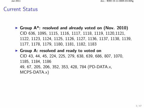
Group A*: resolved and already voted on (Nov. 2010)CID 636, 1095, 1115, 1116, 1117, 1118, 1119, 1120,1121,1122, 1123, 1124, 1125, 1126, 1127, 1136, 1137, 1138, 1139,1177, 1178, 1179, 1180, 1181, 1182, 1183
Group A: resolved and ready to voted onCID 43, 44, 45, 224, 225, 279, 638, 639, 686, 807, 1070,1185, 1184, 118649, 67, 205, 206, 352, 353, 428, 784 (PD-DATA.x,MCPS-DATA.x)
3 / 47
Jan 2011 doc.: IEEE 15-11-0005-03-004g
Current Status
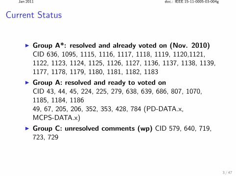
Group A*: resolved and already voted on (Nov. 2010)CID 636, 1095, 1115, 1116, 1117, 1118, 1119, 1120,1121,1122, 1123, 1124, 1125, 1126, 1127, 1136, 1137, 1138, 1139,1177, 1178, 1179, 1180, 1181, 1182, 1183
Group A: resolved and ready to voted onCID 43, 44, 45, 224, 225, 279, 638, 639, 686, 807, 1070,1185, 1184, 118649, 67, 205, 206, 352, 353, 428, 784 (PD-DATA.x,MCPS-DATA.x)
Group C: unresolved comments (wp) CID 579, 640, 719,723, 729
3 / 47
Jan 2011 doc.: IEEE 15-11-0005-03-004g
(A) CID 43
Comment:
Section 6.12c: This bullet list repeats normative text given inTable 1.
delete redundant text
4 / 47
Jan 2011 doc.: IEEE 15-11-0005-03-004g
(A) CID 43
Comment:
Section 6.12c: This bullet list repeats normative text given inTable 1.
delete redundant text
Response:
Accept in principle.
4 / 47
Jan 2011 doc.: IEEE 15-11-0005-03-004g
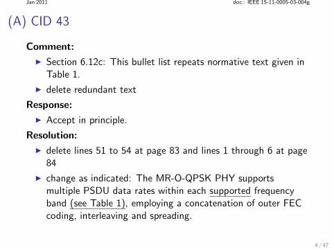
(A) CID 43
Comment:
Section 6.12c: This bullet list repeats normative text given inTable 1.
delete redundant text
Response:
Accept in principle.
Resolution:
delete lines 51 to 54 at page 83 and lines 1 through 6 at page84
change as indicated: The MR-O-QPSK PHY supportsmultiple PSDU data rates within each supported frequencyband (see Table 1), employing a concatenation of outer FECcoding, interleaving and spreading.
4 / 47
Jan 2011 doc.: IEEE 15-11-0005-03-004g
(A) CID 44
Comment:
The sentence ”At least one of the defined frequency bandsshall be implemented when supporting SUN applications” isincorrect (not all SUN applications will require MR-O-QPSKPHYs).
change to: “An MR-O-QPSK compliant device shall supportat least one of the frequency bands designated in Table 1”.
5 / 47
Jan 2011 doc.: IEEE 15-11-0005-03-004g
(A) CID 44
Comment:
The sentence ”At least one of the defined frequency bandsshall be implemented when supporting SUN applications” isincorrect (not all SUN applications will require MR-O-QPSKPHYs).
change to: “An MR-O-QPSK compliant device shall supportat least one of the frequency bands designated in Table 1”.
Response:
Accept.
5 / 47
Jan 2011 doc.: IEEE 15-11-0005-03-004g
(A) CID 45
Comment:
If the PHR is transmitted using DSSS and only the PSDUmay be sent using MDSSS, how is it possible for a compliantdevice to implement only MDSSS?
Clarify what is required for an MR-O-QPSK implementationto be conform.
6 / 47
Jan 2011 doc.: IEEE 15-11-0005-03-004g
(A) CID 45
Comment:
If the PHR is transmitted using DSSS and only the PSDUmay be sent using MDSSS, how is it possible for a compliantdevice to implement only MDSSS?
Clarify what is required for an MR-O-QPSK implementationto be conform.
Response:
Accept in principle.
6 / 47
Jan 2011 doc.: IEEE 15-11-0005-03-004g
cont. CID 45
Resolution:
In principle, the “SpreadingMode” is only relevant for thePSDU and has nothing do do with the PHR.
7 / 47
Jan 2011 doc.: IEEE 15-11-0005-03-004g
cont. CID 45
Resolution:
In principle, the “SpreadingMode” is only relevant for thePSDU and has nothing do do with the PHR.
The specification of PHR coding and spreading offer:
7 / 47
Jan 2011 doc.: IEEE 15-11-0005-03-004g
cont. CID 45
Resolution:
In principle, the “SpreadingMode” is only relevant for thePSDU and has nothing do do with the PHR.
The specification of PHR coding and spreading offer: the lowest data rate and therefore most robust transmission
mode,
7 / 47
Jan 2011 doc.: IEEE 15-11-0005-03-004g
cont. CID 45
Resolution:
In principle, the “SpreadingMode” is only relevant for thePSDU and has nothing do do with the PHR.
The specification of PHR coding and spreading offer: the lowest data rate and therefore most robust transmission
mode, the option for non-coherent detection due to bit differential
encoding (BDE),
7 / 47
Jan 2011 doc.: IEEE 15-11-0005-03-004g
cont. CID 45
Resolution:
In principle, the “SpreadingMode” is only relevant for thePSDU and has nothing do do with the PHR.
The specification of PHR coding and spreading offer: the lowest data rate and therefore most robust transmission
mode, the option for non-coherent detection due to bit differential
encoding (BDE), the simplest spreading scheme: (N, 1)-DSSS,
7 / 47
Jan 2011 doc.: IEEE 15-11-0005-03-004g
cont. CID 45
Resolution:
In principle, the “SpreadingMode” is only relevant for thePSDU and has nothing do do with the PHR.
The specification of PHR coding and spreading offer: the lowest data rate and therefore most robust transmission
mode, the option for non-coherent detection due to bit differential
encoding (BDE), the simplest spreading scheme: (N, 1)-DSSS, the lowest complexity of the decoder for FEC (operating at the
lowest data rate)
7 / 47
Jan 2011 doc.: IEEE 15-11-0005-03-004g
cont. CID 45
Resolution:
In principle, the “SpreadingMode” is only relevant for thePSDU and has nothing do do with the PHR.
The specification of PHR coding and spreading offer: the lowest data rate and therefore most robust transmission
mode, the option for non-coherent detection due to bit differential
encoding (BDE), the simplest spreading scheme: (N, 1)-DSSS, the lowest complexity of the decoder for FEC (operating at the
lowest data rate) offers the simplest way to compute soft values for outer FEC.
In contrast to (N, 4)-DSSS or (N, 8)-MDSSS, there are onlytwo a posteriori values to be computed when SISO decoding a(N, 1) block code.
7 / 47
Jan 2011 doc.: IEEE 15-11-0005-03-004g
cont. CID 45
However, a device supporting mandatory FEC and spreadingspecified for the PHR will most likely support SpreadingMode“DSSS” and RateMode zero.
8 / 47
Jan 2011 doc.: IEEE 15-11-0005-03-004g
cont. CID 45
However, a device supporting mandatory FEC and spreadingspecified for the PHR will most likely support SpreadingMode“DSSS” and RateMode zero.
uses the same spreading and coding scheme
8 / 47
Jan 2011 doc.: IEEE 15-11-0005-03-004g
cont. CID 45
However, a device supporting mandatory FEC and spreadingspecified for the PHR will most likely support SpreadingMode“DSSS” and RateMode zero.
uses the same spreading and coding scheme
only the interleaver depth is slightly different: PHR: 60 code bits PSDU: 176 code bits
8 / 47
Jan 2011 doc.: IEEE 15-11-0005-03-004g
cont. CID 45For the sake of clarity, it is therefore most useful to specifycompliance in the following way:
9 / 47
Jan 2011 doc.: IEEE 15-11-0005-03-004g
cont. CID 45For the sake of clarity, it is therefore most useful to specifycompliance in the following way:
At 6.12c, delete and change as indicated: “For the frequencybands 779-787 MHz, 917-923.5 MHz, 902-928 MHz and2400-2450 MHz, the MR-O-QPSK PHY supports aco-alternative an alternative spreading mode during the PSDUpart, called multiplexed direct sequence spread spectrum(MDSSS).For those frequency bands, a compliant to this PHYshall support at least one of the spreading modes ... For agiven frequency band, it is recommended to implement atleast RateMode zero with SpreadingMode DSSS, since for thismode, coding and spreading is similar to coding and spreadingof the PHR (see 6.12c.1.3 and 6.12c.1.4).”
At 6.12c add : “A compliant device shall implement at leastRateMode zero with SpreadingMode DSSS. All other possiblecombinations of RateMode and SpreadingMode (dependingon the frequency band) are optional.”
9 / 47

Jan 2011 doc.: IEEE 15-11-0005-03-004g
(A) CID 225Comment:
The Header Check Sequence (HCS) field is 8 bits in lengthand contains an 8-bit ITU-T CRC.” The text then describesthe HCS calculations in detail, which represents a duplicationof the description.
Either reference the ITU-T document in detail and delete thefollowing text describing the HCS (preferred), or delete thereference to the ITU-T.
10 / 47
Jan 2011 doc.: IEEE 15-11-0005-03-004g
(A) CID 225Comment:
The Header Check Sequence (HCS) field is 8 bits in lengthand contains an 8-bit ITU-T CRC.” The text then describesthe HCS calculations in detail, which represents a duplicationof the description.
Either reference the ITU-T document in detail and delete thefollowing text describing the HCS (preferred), or delete thereference to the ITU-T.
Response:
Accept in principle.
Resolution:
Detailed description preferred, since it gives a clear guidelinefor the implementer.
Change as indicated: The Header Check Sequence (HCS) field(H7 − H0) is 8 bits in length and contains an 8-bit ITU-TCRC. The HCS is calculated over the first 16 PHR bits ...
10 / 47
Jan 2011 doc.: IEEE 15-11-0005-03-004g
(A) CID 224, 807
Comment:
Confusion about “reserved bits”
What does it mean that they “shall be set to zero if notused?”
11 / 47
Jan 2011 doc.: IEEE 15-11-0005-03-004g
(A) CID 224, 807
Comment:
Confusion about “reserved bits”
What does it mean that they “shall be set to zero if notused?”
Response:
Accept in principle.
11 / 47
Jan 2011 doc.: IEEE 15-11-0005-03-004g
(A) CID 224, 807
Resolution:
The reserved bits cannot be completely ignored on receive,since the evaluation of the HCS depends on them.
Proposed change: “The field (R1 − R0) shall be reserved forfuture usage”.
12 / 47
Jan 2011 doc.: IEEE 15-11-0005-03-004g
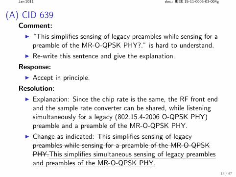
(A) CID 639Comment:
“This simplifies sensing of legacy preambles while sensing for apreamble of the MR-O-QPSK PHY?.” is hard to understand.
Re-write this sentence and give the explanation.
13 / 47
Jan 2011 doc.: IEEE 15-11-0005-03-004g
(A) CID 639Comment:
“This simplifies sensing of legacy preambles while sensing for apreamble of the MR-O-QPSK PHY?.” is hard to understand.
Re-write this sentence and give the explanation.
Response:
Accept in principle.
13 / 47
Jan 2011 doc.: IEEE 15-11-0005-03-004g
(A) CID 639Comment:
“This simplifies sensing of legacy preambles while sensing for apreamble of the MR-O-QPSK PHY?.” is hard to understand.
Re-write this sentence and give the explanation.
Response:
Accept in principle.
Resolution:
Explanation: Since the chip rate is the same, the RF front endand the sample rate converter can be shared, while listeningsimultaneously for a legacy (802.15.4-2006 O-QPSK PHY)preamble and a preamble of the MR-O-QPSK PHY.
Change as indicated: This simplifies sensing of legacypreambles while sensing for a preamble of the MR-O-QPSKPHY.This simplifies simultaneous sensing of legacy preamblesand preambles of the MR-O-QPSK PHY.
13 / 47
Jan 2011 doc.: IEEE 15-11-0005-03-004g
(A) CID 1185
Comment:
Lower data rate should be considered in 470-510 MHz bandfor improved link budget.
Add new data rate of 6.25 kbps with (8,1)-DSSS and rate 1/2FEC.
14 / 47
Jan 2011 doc.: IEEE 15-11-0005-03-004g
(A) CID 1185
Comment:
Lower data rate should be considered in 470-510 MHz bandfor improved link budget.
Add new data rate of 6.25 kbps with (8,1)-DSSS and rate 1/2FEC.
Response:
Accept in principle.
14 / 47
Jan 2011 doc.: IEEE 15-11-0005-03-004g
cont. CID 1185
Resolution:
Add the new spreading mode to all supported frequency bandswhere narrow band DSSS is applied:
15 / 47
Jan 2011 doc.: IEEE 15-11-0005-03-004g
cont. CID 1185
Resolution:
Add the new spreading mode to all supported frequency bandswhere narrow band DSSS is applied:
470-510 MHz
15 / 47
Jan 2011 doc.: IEEE 15-11-0005-03-004g
cont. CID 1185
Resolution:
Add the new spreading mode to all supported frequency bandswhere narrow band DSSS is applied:
470-510 MHz 868-870 MHz
15 / 47
Jan 2011 doc.: IEEE 15-11-0005-03-004g
cont. CID 1185
Resolution:
Add the new spreading mode to all supported frequency bandswhere narrow band DSSS is applied:
470-510 MHz 868-870 MHz 950-958 MHz
15 / 47
Jan 2011 doc.: IEEE 15-11-0005-03-004g
cont. CID 1185
Resolution:
Add the new spreading mode to all supported frequency bandswhere narrow band DSSS is applied:
470-510 MHz 868-870 MHz 950-958 MHz
All those frequency bands are subject to constrained outputpower.
15 / 47
Jan 2011 doc.: IEEE 15-11-0005-03-004g
cont. CID 1185
16 / 47
Jan 2011 doc.: IEEE 15-11-0005-03-004g
cont. CID 1185
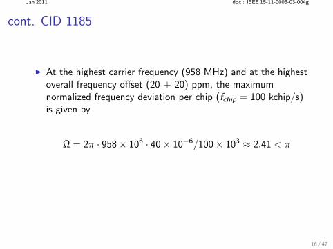
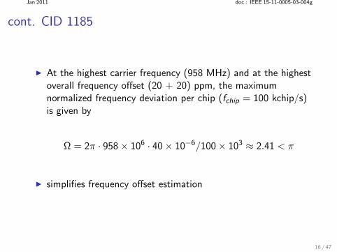
At the highest carrier frequency (958 MHz) and at the highestoverall frequency offset (20 + 20) ppm, the maximumnormalized frequency deviation per chip (fchip = 100 kchip/s)is given by
Ω = 2π · 958 × 106 · 40 × 10−6/100 × 103 ≈ 2.41 < π
16 / 47
Jan 2011 doc.: IEEE 15-11-0005-03-004g
cont. CID 1185
At the highest carrier frequency (958 MHz) and at the highestoverall frequency offset (20 + 20) ppm, the maximumnormalized frequency deviation per chip (fchip = 100 kchip/s)is given by
Ω = 2π · 958 × 106 · 40 × 10−6/100 × 103 ≈ 2.41 < π
simplifies frequency offset estimation
16 / 47
Jan 2011 doc.: IEEE 15-11-0005-03-004g
cont. CID 1185
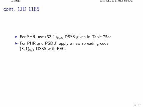
For SHR, use (32, 1)k=0-DSSS given in Table 75aa
17 / 47
Jan 2011 doc.: IEEE 15-11-0005-03-004g
cont. CID 1185
For SHR, use (32, 1)k=0-DSSS given in Table 75aa
For PHR and PSDU, apply a new spreading code(8, 1)0/1-DSSS with FEC.
17 / 47
Jan 2011 doc.: IEEE 15-11-0005-03-004g
cont. CID 1185
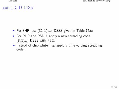
For SHR, use (32, 1)k=0-DSSS given in Table 75aa
For PHR and PSDU, apply a new spreading code(8, 1)0/1-DSSS with FEC.
Instead of chip whitening, apply a time varying spreadingcode.
17 / 47
Jan 2011 doc.: IEEE 15-11-0005-03-004g
cont. CID 1185
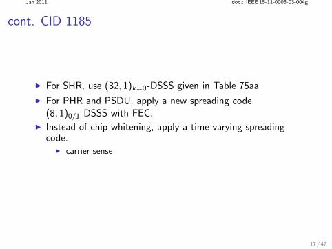
For SHR, use (32, 1)k=0-DSSS given in Table 75aa
For PHR and PSDU, apply a new spreading code(8, 1)0/1-DSSS with FEC.
Instead of chip whitening, apply a time varying spreadingcode.
carrier sense
17 / 47
Jan 2011 doc.: IEEE 15-11-0005-03-004g
cont. CID 1185
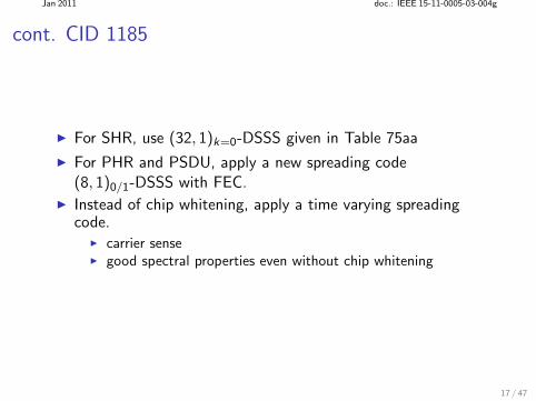
For SHR, use (32, 1)k=0-DSSS given in Table 75aa
For PHR and PSDU, apply a new spreading code(8, 1)0/1-DSSS with FEC.
Instead of chip whitening, apply a time varying spreadingcode.
carrier sense good spectral properties even without chip whitening
17 / 47
Jan 2011 doc.: IEEE 15-11-0005-03-004g
cont. CID 1185
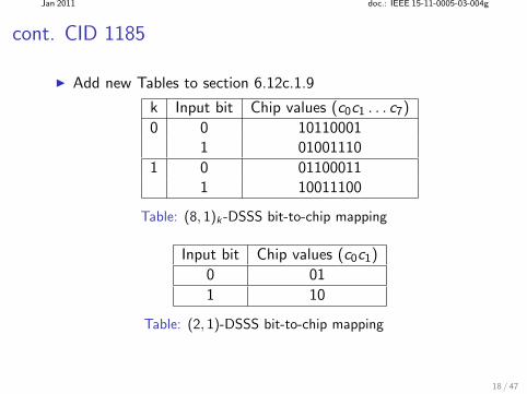
Add new Tables to section 6.12c.1.9
k Input bit Chip values (c0c1 . . . c7)
0 0 101100011 01001110
1 0 011000111 10011100
Table: (8, 1)k -DSSS bit-to-chip mapping
Input bit Chip values (c0c1)
0 01
1 10
Table: (2, 1)-DSSS bit-to-chip mapping
18 / 47
Jan 2011 doc.: IEEE 15-11-0005-03-004g
cont. CID 1185
In section 6.12c.1.9, unify description for (N, 1)0/1-DSSS forN = 8,16 and 32.
19 / 47
Jan 2011 doc.: IEEE 15-11-0005-03-004g
cont. CID 1185
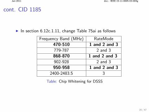
In section 6.12c.1.11, change Table 75ai as follows
Frequency Band (MHz) RateMode
470-510 1 and 2 and 3
779-787 2 and 3
868-870 1 and 2 and 3
902-928 2 and 3
950-958 1 and 2 and 3
2400-2483.5 3
Table: Chip Whitening for DSSS
20 / 47
Jan 2011 doc.: IEEE 15-11-0005-03-004g
cont. CID 1185
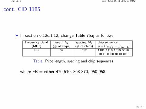
In section 6.12c.1.12, change Table 75aj as follows
Frequency Band length Np spacing Mp chip sequence(MHz) (# of chips) (# of chips) p = (p0, p1, ..., pNp−1)
FB 32 512 1101 1110 1010 00100111 0000 0110 0101
Table: Pilot length, spacing and chip sequences
where FB = either 470-510, 868-870, 950-958.
21 / 47
Jan 2011 doc.: IEEE 15-11-0005-03-004g
cont. CID 1185
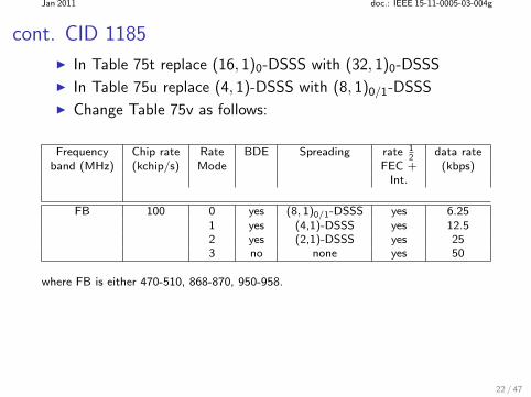
In Table 75t replace (16, 1)0-DSSS with (32, 1)0-DSSS
In Table 75u replace (4, 1)-DSSS with (8, 1)0/1-DSSS
Change Table 75v as follows:
Frequency Chip rate Rate BDE Spreading rate 12
data rateband (MHz) (kchip/s) Mode FEC + (kbps)
Int.
FB 100 0 yes (8, 1)0/1-DSSS yes 6.251 yes (4,1)-DSSS yes 12.52 yes (2,1)-DSSS yes 253 no none yes 50
where FB is either 470-510, 868-870, 950-958.
22 / 47
Jan 2011 doc.: IEEE 15-11-0005-03-004g
cont. CID 1185
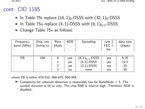
In Table 75t replace (16, 1)0-DSSS with (32, 1)0-DSSS
In Table 75u replace (4, 1)-DSSS with (8, 1)0/1-DSSS
Change Table 75v as follows:
Frequency Chip rate Rate BDE Spreading rate 12
data rateband (MHz) (kchip/s) Mode FEC + (kbps)
Int.
FB 100 0 yes (8, 1)0/1-DSSS yes 6.251 yes (4,1)-DSSS yes 12.52 yes (2,1)-DSSS yes 253 no none yes 50
where FB is either 470-510, 868-870, 950-958.
Complexity for coherent detection is reasonably low for RateMode = 3. Thesymbol duration is 10 us only. The chip SNR is relative high. Therefore, BDE isdisabled.
22 / 47
Jan 2011 doc.: IEEE 15-11-0005-03-004g
cont. CID 1185
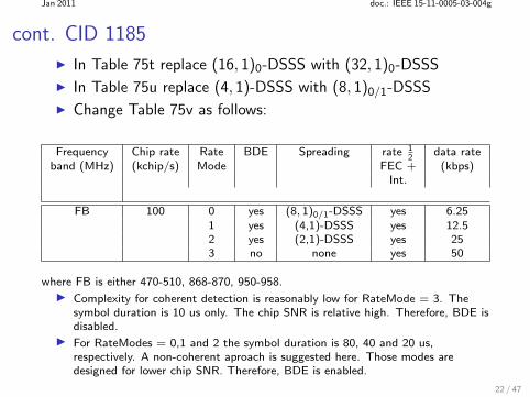
In Table 75t replace (16, 1)0-DSSS with (32, 1)0-DSSS
In Table 75u replace (4, 1)-DSSS with (8, 1)0/1-DSSS
Change Table 75v as follows:
Frequency Chip rate Rate BDE Spreading rate 12
data rateband (MHz) (kchip/s) Mode FEC + (kbps)
Int.
FB 100 0 yes (8, 1)0/1-DSSS yes 6.251 yes (4,1)-DSSS yes 12.52 yes (2,1)-DSSS yes 253 no none yes 50
where FB is either 470-510, 868-870, 950-958.
Complexity for coherent detection is reasonably low for RateMode = 3. Thesymbol duration is 10 us only. The chip SNR is relative high. Therefore, BDE isdisabled.
For RateModes = 0,1 and 2 the symbol duration is 80, 40 and 20 us,respectively. A non-coherent aproach is suggested here. Those modes aredesigned for lower chip SNR. Therefore, BDE is enabled.
22 / 47
Jan 2011 doc.: IEEE 15-11-0005-03-004g
cont. CID 1185
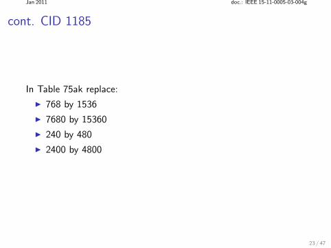
In Table 75ak replace:
768 by 1536
7680 by 15360
240 by 480
2400 by 4800
23 / 47
Jan 2011 doc.: IEEE 15-11-0005-03-004g
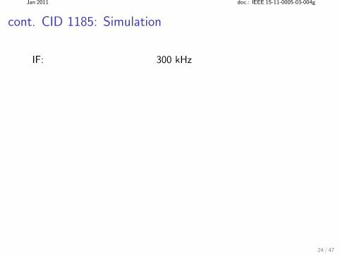
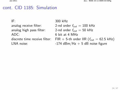
cont. CID 1185: Simulation
IF: 300 kHz
24 / 47
Jan 2011 doc.: IEEE 15-11-0005-03-004g
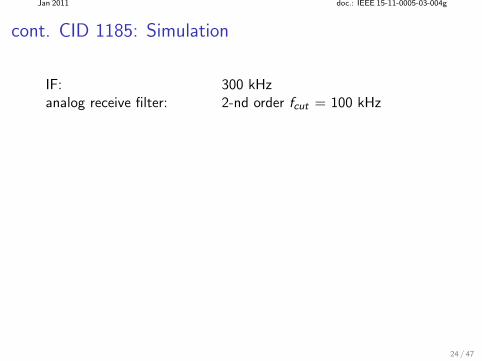
cont. CID 1185: Simulation
IF: 300 kHzanalog receive filter: 2-nd order fcut = 100 kHz
24 / 47

Jan 2011 doc.: IEEE 15-11-0005-03-004g
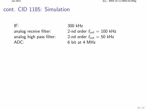
cont. CID 1185: Simulation
IF: 300 kHzanalog receive filter: 2-nd order fcut = 100 kHzanalog high pass filter: 2-nd order fcut = 50 kHz
24 / 47
Jan 2011 doc.: IEEE 15-11-0005-03-004g
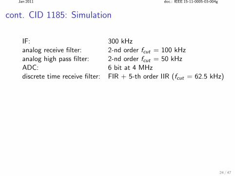
cont. CID 1185: Simulation
IF: 300 kHzanalog receive filter: 2-nd order fcut = 100 kHzanalog high pass filter: 2-nd order fcut = 50 kHzADC: 6 bit at 4 MHz
24 / 47
Jan 2011 doc.: IEEE 15-11-0005-03-004g
cont. CID 1185: Simulation
IF: 300 kHzanalog receive filter: 2-nd order fcut = 100 kHzanalog high pass filter: 2-nd order fcut = 50 kHzADC: 6 bit at 4 MHzdiscrete time receive filter: FIR + 5-th order IIR (fcut = 62.5 kHz)
24 / 47
Jan 2011 doc.: IEEE 15-11-0005-03-004g
cont. CID 1185: Simulation
IF: 300 kHzanalog receive filter: 2-nd order fcut = 100 kHzanalog high pass filter: 2-nd order fcut = 50 kHzADC: 6 bit at 4 MHzdiscrete time receive filter: FIR + 5-th order IIR (fcut = 62.5 kHz)LNA noise: -174 dBm/Hz + 5 dB noise figure
24 / 47
Jan 2011 doc.: IEEE 15-11-0005-03-004g
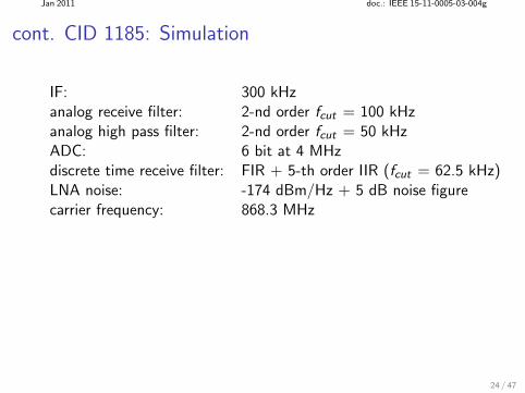
cont. CID 1185: Simulation
IF: 300 kHzanalog receive filter: 2-nd order fcut = 100 kHzanalog high pass filter: 2-nd order fcut = 50 kHzADC: 6 bit at 4 MHzdiscrete time receive filter: FIR + 5-th order IIR (fcut = 62.5 kHz)LNA noise: -174 dBm/Hz + 5 dB noise figurecarrier frequency: 868.3 MHz
24 / 47
Jan 2011 doc.: IEEE 15-11-0005-03-004g
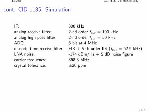
cont. CID 1185: Simulation
IF: 300 kHzanalog receive filter: 2-nd order fcut = 100 kHzanalog high pass filter: 2-nd order fcut = 50 kHzADC: 6 bit at 4 MHzdiscrete time receive filter: FIR + 5-th order IIR (fcut = 62.5 kHz)LNA noise: -174 dBm/Hz + 5 dB noise figurecarrier frequency: 868.3 MHzcrystal tolerance: ±20 ppm
24 / 47
Jan 2011 doc.: IEEE 15-11-0005-03-004g
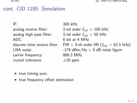
cont. CID 1185: Simulation
IF: 300 kHzanalog receive filter: 2-nd order fcut = 100 kHzanalog high pass filter: 2-nd order fcut = 50 kHzADC: 6 bit at 4 MHzdiscrete time receive filter: FIR + 5-th order IIR (fcut = 62.5 kHz)LNA noise: -174 dBm/Hz + 5 dB noise figurecarrier frequency: 868.3 MHzcrystal tolerance: ±20 ppm
true timing sync
true frequency offset estimation
24 / 47
Jan 2011 doc.: IEEE 15-11-0005-03-004g
cont. CID 1185
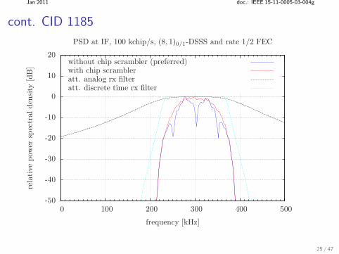
-50
-40
-30
-20
-10
0
10
20
0 100 200 300 400 500
rela
tive
pow
ersp
ectr
alden
sity
[dB
]
frequency [kHz]
PSD at IF, 100 kchip/s, (8, 1)0/1-DSSS and rate 1/2 FEC
without chip scrambler (preferred)with chip scrambleratt. analog rx filteratt. discrete time rx filter
25 / 47
Jan 2011 doc.: IEEE 15-11-0005-03-004g
cont. CID 1185
10−3
10−2
10−1
100
-124 -123 -122 -121 -120 -119
fram
eer
ror
rate
(FE
R)
receive power [dBm]
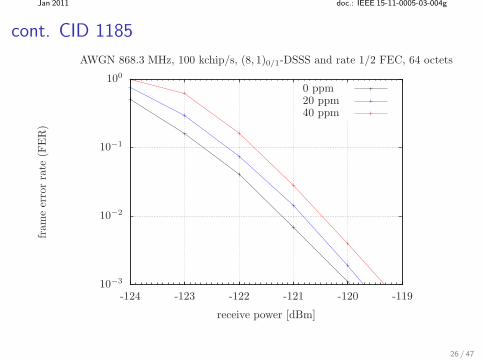
AWGN 868.3 MHz, 100 kchip/s, (8, 1)0/1-DSSS and rate 1/2 FEC, 64 octets
0 ppm20 ppm40 ppm
26 / 47
Jan 2011 doc.: IEEE 15-11-0005-03-004g
(A) CID 638, 1186
Comment:
Cross correlation of (8,4)-DSSS code is poor
Non-coherent detection is not possible
Consider (8,4)-DSSS code given in 15-10-0281-04-004g
Response:
Reject.
27 / 47
Jan 2011 doc.: IEEE 15-11-0005-03-004g
cont. CID 638, 1186
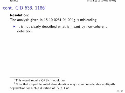
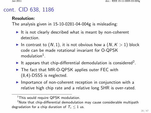
Resolution:The analysis given in 15-10-0281-04-004g is misleading:
1This would require QPSK modulation.2Note that chip-differential demodulation may cause considerable multipath
degradation for a chip duration of Tc ≤ 1 us.28 / 47
Jan 2011 doc.: IEEE 15-11-0005-03-004g
cont. CID 638, 1186
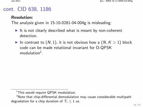
Resolution:The analysis given in 15-10-0281-04-004g is misleading:
It is not clearly described what is meant by non-coherentdetection.
1This would require QPSK modulation.2Note that chip-differential demodulation may cause considerable multipath
degradation for a chip duration of Tc ≤ 1 us.28 / 47
Jan 2011 doc.: IEEE 15-11-0005-03-004g
cont. CID 638, 1186
Resolution:The analysis given in 15-10-0281-04-004g is misleading:
It is not clearly described what is meant by non-coherentdetection.
In contrast to (N, 1), it is not obvious how a (N, K > 1) blockcode can be made rotational invariant for O-QPSKmodulation1.
1This would require QPSK modulation.2Note that chip-differential demodulation may cause considerable multipath
degradation for a chip duration of Tc ≤ 1 us.28 / 47
Jan 2011 doc.: IEEE 15-11-0005-03-004g
cont. CID 638, 1186
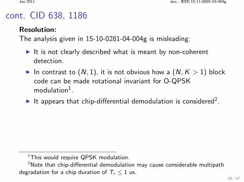
Resolution:The analysis given in 15-10-0281-04-004g is misleading:
It is not clearly described what is meant by non-coherentdetection.
In contrast to (N, 1), it is not obvious how a (N, K > 1) blockcode can be made rotational invariant for O-QPSKmodulation1.
It appears that chip-differential demodulation is considered2.
1This would require QPSK modulation.2Note that chip-differential demodulation may cause considerable multipath
degradation for a chip duration of Tc ≤ 1 us.28 / 47
Jan 2011 doc.: IEEE 15-11-0005-03-004g
cont. CID 638, 1186
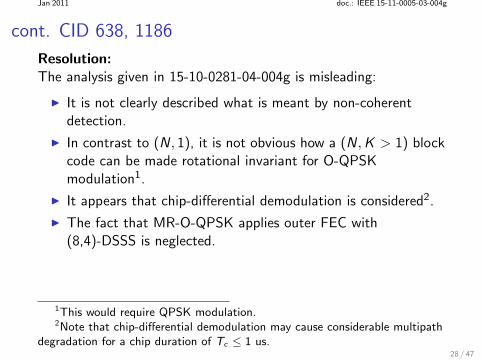
Resolution:The analysis given in 15-10-0281-04-004g is misleading:
It is not clearly described what is meant by non-coherentdetection.
In contrast to (N, 1), it is not obvious how a (N, K > 1) blockcode can be made rotational invariant for O-QPSKmodulation1.
It appears that chip-differential demodulation is considered2.
The fact that MR-O-QPSK applies outer FEC with(8,4)-DSSS is neglected.
1This would require QPSK modulation.2Note that chip-differential demodulation may cause considerable multipath
degradation for a chip duration of Tc ≤ 1 us.28 / 47
Jan 2011 doc.: IEEE 15-11-0005-03-004g
cont. CID 638, 1186
Resolution:The analysis given in 15-10-0281-04-004g is misleading:
It is not clearly described what is meant by non-coherentdetection.
In contrast to (N, 1), it is not obvious how a (N, K > 1) blockcode can be made rotational invariant for O-QPSKmodulation1.
It appears that chip-differential demodulation is considered2.
The fact that MR-O-QPSK applies outer FEC with(8,4)-DSSS is neglected.
Importance of non-coherent reception in conjunction with arelative high chip rate and a relative long SHR is over-rated.
1This would require QPSK modulation.2Note that chip-differential demodulation may cause considerable multipath
degradation for a chip duration of Tc ≤ 1 us.28 / 47
Jan 2011 doc.: IEEE 15-11-0005-03-004g
cont. CID 638, 1186
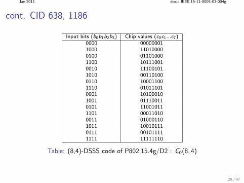
Input bits (b0b1b2b3) Chip values (c0c1...c7)0000 000000011000 110100000100 011010001100 101110010010 111001011010 001101000110 100011001110 010111010001 101000101001 011100110101 110010111101 000110100011 010001101011 100101110111 001011111111 11111110
Table: (8,4)-DSSS code of P802.15.4g/D2 : C0(8, 4)
29 / 47
Jan 2011 doc.: IEEE 15-11-0005-03-004g
cont. CID 638, 1186
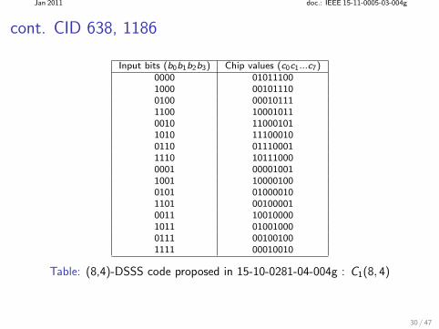
Input bits (b0b1b2b3) Chip values (c0c1...c7)0000 010111001000 001011100100 000101111100 100010110010 110001011010 111000100110 011100011110 101110000001 000010011001 100001000101 010000101101 001000010011 100100001011 010010000111 001001001111 00010010
Table: (8,4)-DSSS code proposed in 15-10-0281-04-004g : C1(8, 4)
30 / 47
Jan 2011 doc.: IEEE 15-11-0005-03-004g
cont. CID 638, 1186
In conjunction with FEC, inner non-coherent detection isusually not recommended.
31 / 47
Jan 2011 doc.: IEEE 15-11-0005-03-004g
cont. CID 638, 1186
In conjunction with FEC, inner non-coherent detection isusually not recommended.
For MR-O-QPSK, support for inner non-coherent detectionusing (N, 1)-DSSS in conjunction with BDE is a compromise(see doc IEEE 802.15-10-0435-02-004g for further details).
For (8,4)-DSSS, the chip SNR is relative high (at thesensitivity limit).
Moderate implementation complexity of a phase control loop
The very first pilot signal during PSDU simplifies initial phaseestimation.
31 / 47
Jan 2011 doc.: IEEE 15-11-0005-03-004g
cont. CID 638, 1186
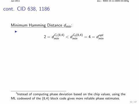
Minimum Hamming Distance dmin:
2 = dC1(8,4)min < d
C0(8,4)min = 4 = d
optmin
3Instead of computing phase deviation based on the chip values, using theML codeword of the (8,4) block code gives more reliable phase estimates.
32 / 47
Jan 2011 doc.: IEEE 15-11-0005-03-004g
cont. CID 638, 1186
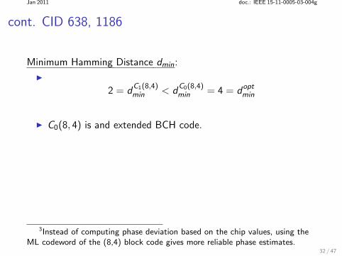
Minimum Hamming Distance dmin:
2 = dC1(8,4)min < d
C0(8,4)min = 4 = d
optmin
C0(8, 4) is and extended BCH code.
3Instead of computing phase deviation based on the chip values, using theML codeword of the (8,4) block code gives more reliable phase estimates.
32 / 47
Jan 2011 doc.: IEEE 15-11-0005-03-004g
cont. CID 638, 1186
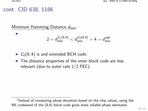
Minimum Hamming Distance dmin:
2 = dC1(8,4)min < d
C0(8,4)min = 4 = d
optmin
C0(8, 4) is and extended BCH code.
The distance properties of the inner block code are lessrelevant (due to outer rate 1/2 FEC).
3Instead of computing phase deviation based on the chip values, using theML codeword of the (8,4) block code gives more reliable phase estimates.
32 / 47
Jan 2011 doc.: IEEE 15-11-0005-03-004g
cont. CID 638, 1186
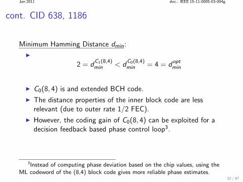
Minimum Hamming Distance dmin:
2 = dC1(8,4)min < d
C0(8,4)min = 4 = d
optmin
C0(8, 4) is and extended BCH code.
The distance properties of the inner block code are lessrelevant (due to outer rate 1/2 FEC).
However, the coding gain of C0(8, 4) can be exploited for adecision feedback based phase control loop3.
3Instead of computing phase deviation based on the chip values, using theML codeword of the (8,4) block code gives more reliable phase estimates.
32 / 47
Jan 2011 doc.: IEEE 15-11-0005-03-004g
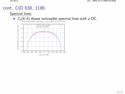
cont. CID 638, 1186Spectral lines:
C1(8, 4) shows noticeable spectral lines with a DC.
-40
-30
-20
-10
0
10
20
-1000 -800 -600 -400 -200 0 200 400 600 800 1000
norm
ailiz
edpow
ersp
ectr
alden
sity
[dB
]
frequency [kHz]
PSD, random PSDU, 1000 kchip/s, C1(8, 4)-DSSS and rate 1/2 FEC
without chip scramblerwith chip scrambler
33 / 47
Jan 2011 doc.: IEEE 15-11-0005-03-004g
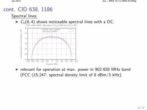
cont. CID 638, 1186Spectral lines:
C1(8, 4) shows noticeable spectral lines with a DC.
-40
-30
-20
-10
0
10
20
-1000 -800 -600 -400 -200 0 200 400 600 800 1000
norm
ailiz
edpow
ersp
ectr
alden
sity
[dB
]
frequency [kHz]
PSD, random PSDU, 1000 kchip/s, C1(8, 4)-DSSS and rate 1/2 FEC
without chip scramblerwith chip scrambler
relevant for operation at max. power in 902-928 MHz band(FCC §15.247: spectral density limit of 8 dBm/3 kHz).
33 / 47
Jan 2011 doc.: IEEE 15-11-0005-03-004g
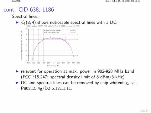
cont. CID 638, 1186Spectral lines:
C1(8, 4) shows noticeable spectral lines with a DC.
-40
-30
-20
-10
0
10
20
-1000 -800 -600 -400 -200 0 200 400 600 800 1000
norm
ailiz
edpow
ersp
ectr
alden
sity
[dB
]
frequency [kHz]
PSD, random PSDU, 1000 kchip/s, C1(8, 4)-DSSS and rate 1/2 FEC
without chip scramblerwith chip scrambler
relevant for operation at max. power in 902-928 MHz band(FCC §15.247: spectral density limit of 8 dBm/3 kHz).
DC and spectral lines can be removed by chip whitening, seeP802.15.4g/D2 6.12c.1.11.
33 / 47
Jan 2011 doc.: IEEE 15-11-0005-03-004g
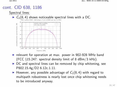
cont. CID 638, 1186Spectral lines:
C1(8, 4) shows noticeable spectral lines with a DC.
-40
-30
-20
-10
0
10
20
-1000 -800 -600 -400 -200 0 200 400 600 800 1000
norm
ailiz
edpow
ersp
ectr
alden
sity
[dB
]
frequency [kHz]
PSD, random PSDU, 1000 kchip/s, C1(8, 4)-DSSS and rate 1/2 FEC
without chip scramblerwith chip scrambler
relevant for operation at max. power in 902-928 MHz band(FCC §15.247: spectral density limit of 8 dBm/3 kHz).
DC and spectral lines can be removed by chip whitening, seeP802.15.4g/D2 6.12c.1.11.
However, any possible advantage of C1(8, 4) with regard tomultipath robustness is nearly lost once chip whitening needsto be introduced anyway.
33 / 47
Jan 2011 doc.: IEEE 15-11-0005-03-004g
(B) CID 205
Comment:
MROQPSKRATEMode shall be a written“MROQPSKRateMode”
Give a more precise description in Table 8.
Alternatively, should be moved to a a PIB, since the PSDUdata rate may not change with every sent frame.
34 / 47
Jan 2011 doc.: IEEE 15-11-0005-03-004g
(B) CID 205
Comment:
MROQPSKRATEMode shall be a written“MROQPSKRateMode”
Give a more precise description in Table 8.
Alternatively, should be moved to a a PIB, since the PSDUdata rate may not change with every sent frame.
Response:
Accept in principle.
34 / 47
Jan 2011 doc.: IEEE 15-11-0005-03-004g
cont. CID 205
Resolution:
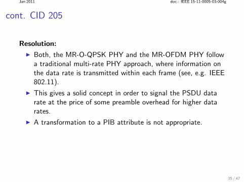
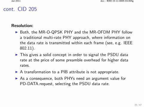
Both, the MR-O-QPSK PHY and the MR-OFDM PHY followa traditional multi-rate PHY approach, where information onthe data rate is transmitted within each frame (see, e.g. IEEE802.11).
35 / 47
Jan 2011 doc.: IEEE 15-11-0005-03-004g
cont. CID 205
Resolution:
Both, the MR-O-QPSK PHY and the MR-OFDM PHY followa traditional multi-rate PHY approach, where information onthe data rate is transmitted within each frame (see, e.g. IEEE802.11).
This gives a solid concept in order to signal the PSDU datarate at the price of some preamble overhead for higher datarates.
A transformation to a PIB attribute is not appropriate.
As a consequence, both PHYs need an argument value forPD-DATA.request, selecting the PSDU data rate.
35 / 47
Jan 2011 doc.: IEEE 15-11-0005-03-004g
cont. CID 205
Since the list of arguments of PD-DATA.request alreadycontains such a variable, namely “DataRate”, this variablecan be overloaded.
change Table 8 “PD-DATA.request parameters” accordingly:
36 / 47
Jan 2011 doc.: IEEE 15-11-0005-03-004g
cont. CID 205
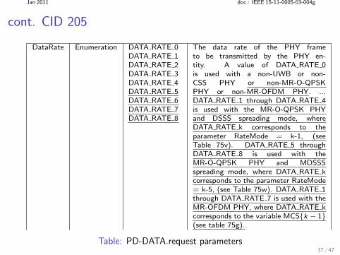
DataRate Enumeration DATA RATE 0DATA RATE 1DATA RATE 2DATA RATE 3DATA RATE 4DATA RATE 5DATA RATE 6DATA RATE 7DATA RATE 8
The data rate of the PHY frameto be transmitted by the PHY en-tity. A value of DATA RATE 0is used with a non-UWB or non-CSS PHY or non-MR-O-QPSKPHY or non-MR-OFDM PHY. ...DATA RATE 1 through DATA RATE 4is used with the MR-O-QPSK PHYand DSSS spreading mode, whereDATA RATE k corresponds to theparameter RateMode = k-1, (seeTable 75v). DATA RATE 5 throughDATA RATE 8 is used with theMR-O-QPSK PHY and MDSSSspreading mode, where DATA RATE kcorresponds to the parameter RateMode= k-5, (see Table 75w). DATA RATE 1through DATA RATE 7 is used with theMR-OFDM PHY, where DATA RATE kcorresponds to the variable MCSk − 1(see table 75g).
Table: PD-DATA.request parameters37 / 47
Jan 2011 doc.: IEEE 15-11-0005-03-004g
cont. CID 205
Apply the same amendment for “DataRate” in the descriptionfor PD-DATA.indication (Table 10).
38 / 47
Jan 2011 doc.: IEEE 15-11-0005-03-004g
cont. CID 205
Apply the same amendment for “DataRate” in the descriptionfor PD-DATA.indication (Table 10).
Delete both “MROQKPSKRateMode” and“MROQKPSKSpreadingMode” in PD-DATA.request andPD-DATA.indication.
38 / 47
Jan 2011 doc.: IEEE 15-11-0005-03-004g
cont. CID 205
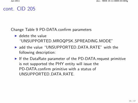
Change Table 9 PD-DATA.confirm parameters
39 / 47

Jan 2011 doc.: IEEE 15-11-0005-03-004g
cont. CID 205
Change Table 9 PD-DATA.confirm parameters
delete the value“UNSUPPORTED MROQPSK SPREADING MODE”
39 / 47
Jan 2011 doc.: IEEE 15-11-0005-03-004g
cont. CID 205
Change Table 9 PD-DATA.confirm parameters
delete the value“UNSUPPORTED MROQPSK SPREADING MODE”
add the value “UNSUPPORTED DATA RATE” with thefollowing description:
39 / 47
Jan 2011 doc.: IEEE 15-11-0005-03-004g
cont. CID 205
Change Table 9 PD-DATA.confirm parameters
delete the value“UNSUPPORTED MROQPSK SPREADING MODE”
add the value “UNSUPPORTED DATA RATE” with thefollowing description:
If the DataRate parameter of the PD-DATA.request primitiveis not supported the PHY entity will issue thePD-DATA.confirm primitive with a status ofUNSUPPORTED DATA RATE.
39 / 47
Jan 2011 doc.: IEEE 15-11-0005-03-004g
cont. CID 205
Change List of MCPS-DATA.request parameters (7.1.1.1.1):
40 / 47
Jan 2011 doc.: IEEE 15-11-0005-03-004g
cont. CID 205
Change List of MCPS-DATA.request parameters (7.1.1.1.1):
add the value “DataRate”
40 / 47
Jan 2011 doc.: IEEE 15-11-0005-03-004g
cont. CID 205
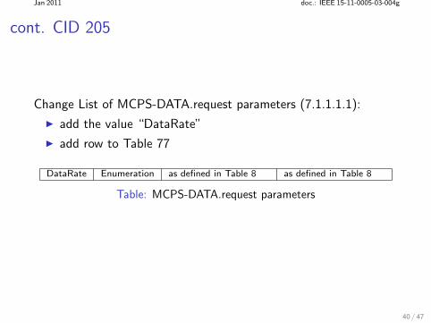
Change List of MCPS-DATA.request parameters (7.1.1.1.1):
add the value “DataRate”
add row to Table 77
DataRate Enumeration as defined in Table 8 as defined in Table 8
Table: MCPS-DATA.request parameters
40 / 47
Jan 2011 doc.: IEEE 15-11-0005-03-004g
cont. CID 205
Change List of MCPS-DATA.indication parameters:
41 / 47
Jan 2011 doc.: IEEE 15-11-0005-03-004g
cont. CID 205
Change List of MCPS-DATA.indication parameters:
add the value “DataRate”
41 / 47
Jan 2011 doc.: IEEE 15-11-0005-03-004g
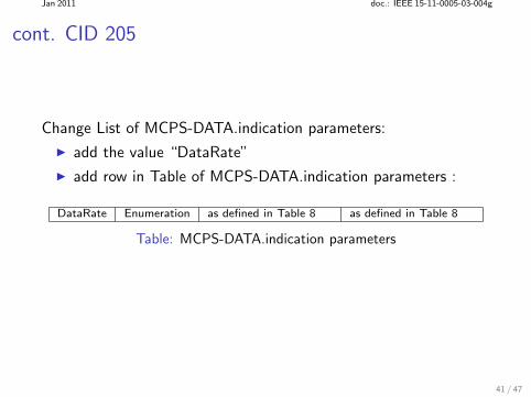
cont. CID 205
Change List of MCPS-DATA.indication parameters:
add the value “DataRate”
add row in Table of MCPS-DATA.indication parameters :
DataRate Enumeration as defined in Table 8 as defined in Table 8
Table: MCPS-DATA.indication parameters
41 / 47
Jan 2011 doc.: IEEE 15-11-0005-03-004g
cont. CID 205
The following comments are solved or obsolete when accepting theresolution of CID 205: CIDs: # 49, 67, 206, 352, 353, 428.
42 / 47
Jan 2011 doc.: IEEE 15-11-0005-03-004g
(B) CID 279
Comment:
CCA timing should be given in symbols
43 / 47
Jan 2011 doc.: IEEE 15-11-0005-03-004g
(B) CID 279
Comment:
CCA timing should be given in symbols
Response:
Accept in principle.
43 / 47

Jan 2011 doc.: IEEE 15-11-0005-03-004g
cont. CID 279
44 / 47
Jan 2011 doc.: IEEE 15-11-0005-03-004g
cont. CID 279
Resolution:
For the MR-O-QPSK PHY, the term “symbol time” is not asstraightforward as in the baseline standard
multi-rate PHY SHR: (N, 1)-DSSS PHR: (N, 1)-DSSS + rate 1/2 FEC + zero-padding PSDU: (N, 1) or (N, 4)-DSSS (N, 8)-MDSSS + rate 1/2 FEC
+ zero-padding + pilot insertion
Suggested solutions: (A) use time of a chip duration as a timing unit (B) use the spreading length of (N, 1)-DSSS w.r.t. the SHR as
the timing unit
44 / 47
Jan 2011 doc.: IEEE 15-11-0005-03-004g
cont. CID 279
45 / 47
Jan 2011 doc.: IEEE 15-11-0005-03-004g
cont. CID 279
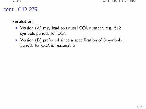
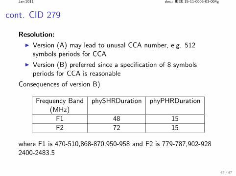
Resolution:
Version (A) may lead to unusal CCA number, e.g. 512symbols periods for CCA
Version (B) preferred since a specification of 8 symbolsperiods for CCA is reasonable
45 / 47
Jan 2011 doc.: IEEE 15-11-0005-03-004g
cont. CID 279
Resolution:
Version (A) may lead to unusal CCA number, e.g. 512symbols periods for CCA
Version (B) preferred since a specification of 8 symbolsperiods for CCA is reasonable
Consequences of version B)
Frequency Band phySHRDuration phyPHRDuration(MHz)
F1 48 15
F2 72 15
where F1 is 470-510,868-870,950-958 and F2 is 779-787,902-9282400-2483.5
45 / 47
Jan 2011 doc.: IEEE 15-11-0005-03-004g
CID 279
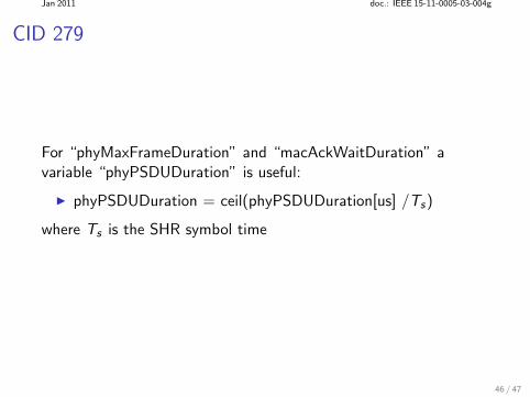
For “phyMaxFrameDuration” and “macAckWaitDuration” avariable “phyPSDUDuration” is useful:
phyPSDUDuration = ceil(phyPSDUDuration[us] /Ts)
where Ts is the SHR symbol time
46 / 47
Jan 2011 doc.: IEEE 15-11-0005-03-004g
cont. CID 279
The following comments are implicitly solved by using the SHRsymbol time as the time unit: CID 686, 1184
47 / 47


![[XLS]TGw Comment Resolutions - IEEE Standards Association · Web viewThe Minimum PHY Rate is in the AP's operational rate set, for an uplink TS. The Minimum PHY Rate is in the non-AP](https://img.pdfslide.us/doc/110x75/5b42eff17f8b9a4f5d8b7e0a/xlstgw-comment-resolutions-ieee-standards-association-web-viewthe-minimum.jpg)