Embed Size (px)
Citation preview
Final Report
Proposed Changes to AS/NZS 4013 – Determination of Particle Emissions Factors
Commissioned study for the Commonwealth Department of the Environment and Heritage
John J Todd1 and Michael Greenwood2
1 Eco-Energy Options Pty Ltd 2 AHHA Testing Laboratory
June 2006
Testing proposed revisions to AS/NZS4013
Disclaimer The research reported in this document was commissioned by the Air Quality Section, Department of the Environment and Heritage. The report carries no formal endorsement by the Department of the Environment and Heritage or the Australian Government nor should any be implied. Contact Details Dr John J Todd
Eco-Energy Options Pty ltd 3 Beltana St, LINDISFARNE, Tas 7015 Australia [email protected] 6243 0335, 0419 307084
Unitas Company Ltd
Private Bag 11, GPO HOBART Tas 7001 Attention: Damian Waters
Page i
Testing proposed revisions to AS/NZS4013
Executive Summary This research was commissioned by the Commonwealth Department of Environment and Heritage to investigate the proposed changes to the Australian and New Zealand Standard for the measurement of particulate emissions from wood-burning residential heating appliances (AS/NZS4013). Emission measurements were made on four models of woodheater. The tests were conducted at the Australian Home Heating Association Laboratory in Adelaide, South Australia between 14 February and 22 April 2005. Emissions were measured for 108 test cycles, including tests conducted to (a) the AS/NZS4013 methodology, (b) the proposed revised methodology and (c) a new real-world protocol methodology. Two of the heater models were modified after initial testing by fitting an automatic air supply triggered by opening the fuel loading door and closed over a predetermined period by a timing device. The proposed revised method differs from the AS/NZS4013 method for medium and low burn-rates in that only two minutes is allowed between adding a new fuel load and turning the combustion air to the medium or low setting (compared to 10 to 20 minutes delay in the AS/NZS4013 method). The key outcomes of the research were:
• All four heaters recorded increased emission factors when tested to the revised method. For two heaters the emission factor doubled and for two heaters it tripled. This strongly supports the assumption that the revised test method is more stringent than the current test method.
• One of the four heaters achieved emission factors less than 4g/kg for both the AS/NZS4013 method and the revised method. The other three heaters ‘failed’ the revised method.
• The one heater that passed when tested to the revised method had a low emission factor when tested to AS/NZS4013 (1.8g/kg). This suggests that some heaters already on the market would meet the 4g/kg limit without modification. It also suggests that some heater models could easily be modified to pass when tested to the revised method, simply by increasing the minimum air supply. There is some evidence to suggest that heaters with smaller fireboxes would be more likely to respond to this type of modification.
• Two of the three heaters that failed the revised method were modified by adding an automatic additional air supply. After modification they both achieved emission factors less than 4g/kg when tested to the revised method.
• This research did not attempt to modify the two heaters for commercial production. The aim was to demonstrate that a simple and inexpensive solution is possible. Commercial modifications would need to be robust and aesthetically acceptable. There is no reason to suspect that this is not possible, although it is unlikely that a simple add-on device would be practical (i.e. some redesign/retooling would be required).
• The modifications used in this research focussed on a door-triggered timing device. Other possibilities are briefly discussed in the report, including temperature triggered systems and improved secondary air systems.
Page ii

Testing proposed revisions to AS/NZS4013
• Automatic controls open up new possibilities for reducing emissions and improving efficiency.
• A new emission test method was developed and trialled as part of this research. Referred to as the ‘real-world protocol’, the method includes measurement of emissions during the light-up phase as well as high, medium and low burn-cycles. After the light-up phase, larger logs are used (i.e. considerably larger than those specified in AS/NZS4013) and a larger total fuel load is used for the low burn. The operation of the heater is intended to more closely reflect use in people’s homes.
• Emission factors for the real-world protocol, when averaged over all four heaters, were the same as the four-heater average for the revised method. Both were 2.5 times larger than the four-heater average for the AS/NZS4013 test method. However, the ranking of the four heaters from cleanest to smokiest altered for each of the three methods.
Recommendations The specific recommendations of the study are as follows:
• The replacement of the current heater standard (AS/NZS4013) with the proposed revised method following further refinement and testing to improve the robustness and technical accuracy of the method. Adoption of a revised method is considered the best approach to reliably linking laboratory results with the emissions produced in people’s homes. The alternative approach of simply reducing emission levels and retaining the present standard is considered less reliable as it failed to reproduce the order of heaters from least smoky to most smoky that could be expected under real life conditions.
• The introduction of stricter requirements for fan use during standard testing; in particular a fan (if fitted) should be operated on its maximum setting for all tests (including slow burn), but that any automatic fan controls should operate normally.
• The addition of a single overnight burn emission cycle as part of standard testing. This burn cycle should have an emission factor cap double the maximum allowed emission factor for the average of high, medium and low burn rates.
• The continued exclusion of the light-up stage (i.e. lighting a cold heater) from the standard test method.
• The requirement that logs must be loaded parallel to the longest firebox axis during testing for heater models where the ratio of the long axis to the short axis exceeds 1:0.5 (or another ratio to be determined through discussion).
• It is also recommended that if these or other changes to the standard test method are adopted they should be included in a single revision, rather than a series of revisions to reduce the likely significant costs to industry of retesting existing heater models.
Page iii
Testing proposed revisions to AS/NZS4013
Table of Contents Report contact details i Executive Summary ii Glossary v 1 Introduction 1 1.1 Project Brief 1 2 Test Methodology 2 2.1 AS/NZS4013 Test Method 2 2.2 Revised Test Method 2 2.3 Real-World Test Protocol 3 2.4 Shortened Test Methods 4 2.5 Heater Modifications 6 2.5.1 Increased minimum air 6 2.5.2 Timer controlled air supply 6 2.5.3 Temperature controlled air supply 7 2.5.4 Flue draft controlled air supply 8 2.5.5 Improved secondary air 8 2.5.6 International developments 8 3 Results 9 3.1 Heater A 9 3.2 Heater B 11 3.3 Heater C 15 3.4 Heater D 19 3.5 Result Summary 24 4 Discussion 26 4.1 Comparison of AS/NZS4013 and the Revised Method 27 4.2 Heater Modifications 27 4.3 Importance of Good Combustion before Slow Burn 28 4.4 Real-World Emission Test Protocol 28 4.5 Do AS/NZS4013 and the Revised Method Give Realistic Emission Measurements 28 4.6 Fan Use on Slow Burn 30 5 Recommendations 30 6 Conclusions 33 Appendix 1 Real-World Protocol Testing (photos) 35 Appendix 2 Heater A: Graphs and tables of test results 38 Appendix 3 Heater B: Graphs and tables of test results 43 Appendix 4 Heater C: Graphs and tables of test results 48 Appendix 5 Heater D: Graphs and tables of test results 55
Page iv
Testing proposed revisions to AS/NZS4013
Glossary Burn cycle the combustion of a load of firewood in a woodheater from
the time the fuel is loaded into the heater to the time the fuel is completely consumed.
Emission factor the mass of particles emitted by a woodheater per kilogram of wood (oven-dry weight basis) burnt in the heater, expressed as grams per kilogram (g/kg).
Emission rate the mass of particles emitted by a woodheater per hour, expressed as grams per hour (g/h), usually averaged over a full burn cycle.
Real-world protocol Refers to an emission test method developed as part of this research, which is intended to represent the way people use woodheaters in their homes.
Revised method Refers to the proposed test method detailed in the public comment draft of the Australian/New Zealand emission standard – DR04554.
Standard test method Refers to the performance and emission test methods detailed in AS/NZS4012:1999 and AS/NZS4013:1999.
Woodheater a residential space heating appliance intended for use with firewood fuels (sometimes written as wood heater or wood-heater). In North America the term used is wood stove, in New Zealand wood burner.
Page v
Testing proposed revisions to AS/NZS4013
1 Introduction Pollution control authorities in Australia and New Zealand have been concerned for some years about the apparent differences in emissions between woodheaters tested under standard conditions in the laboratory and the same heater models used in people’s homes. Anecdotal evidence suggests that emissions when used in the home are much greater than the laboratory-measured emissions. There are several reasons why this might be the case. It is possible that the heater models used for test purposes are different from the models sold to the public. This is being investigated through a series of audits. The audit program in Australia has identified some problems and is now conducting a second stage of testing. It is possible that the firewood used in people’s homes is different to that used in the laboratory tests; in particular the home-use firewood might have high moisture content. Surveys of firewood show that only a small proportion of households have firewood with very high moisture. Furthermore, laboratory tests have not identified firewood moisture as a significant factor in increasing emissions. Thus, wet firewood, while probably contributing to some extent to higher emissions, is unlikely to contribute significantly to the problem. A third possible cause of the apparent large discrepancy between household and laboratory emissions is the laboratory test method itself. If the laboratory test method is not representative of actual use it is possible that large discrepancies in emissions could occur. When the laboratory test method was developed in the early 1990s, a decision was made to base the test method on ‘correct’ use of the heater. Correct use was taken as being operating practices designed to minimise smoke emissions. It was assumed that public education and manufactures’ operating instructions would lead to widespread adoption of correct operating practices. Surveys have indicated that the majority of households do not operate heaters ‘correctly’. Thus, a revision of the method used for testing heaters in the laboratory appears warranted. 1.1 Project Brief The possibility of modifying the current standard test method (as defined in AS/NZS4013) was discussed at a recent standards meeting (September 2004). The Commonwealth Department of the Environment and Heritage is represented on the standards committee and determined that they would commission a study to investigate one of the proposed changes to the standard method. The proposed change under investigation relates to the medium and low burn cycles of the test method. Under the present test method, heaters are operated with maximum combustion air for a period after refuelling before slowing the combustion rate to medium or low. The proposed change involves adjusting the combustion air to medium or low within two minutes of refuelling the heater. In order to investigate this proposed change, a project brief was developed. This project brief was to:
• Select and purchase four woodheater models, encompassing a suitably diverse range of engineering designs;
• Determine particle emissions performance for these four models in accordance with the Australian/New Zealand Standard AS/NSZ 4013:1999 Domestic solid fuel burning appliances – Method for determination of flue gas emission;
Page 1
Testing proposed revisions to AS/NZS4013
• Determine particle emissions performance for these four models in accordance with the Australian/New Zealand Draft Standard DR 04554 Draft for Public Comment Domestic solid fuel burning appliances – Method for determination of flue gas emission;
• Assess engineering design modifications required for currently manufactured woodheaters to comply with the Australian/New Zealand Draft Standard DR 03621 CP Domestic solid fuel burning appliances – Method for determination of flue gas emission; and
• Provide a final Project Report, including full test results and recommendations.
The research study was to be carried out at the Australian Home Heating Association Laboratory in Adelaide. This NATA registered laboratory routinely conducts emission tests on woodheaters. The management of the research program, including the detailed research design, was carried out by Dr John Todd, Eco-Energy Options Pty Ltd, working through Unitas Company Ltd, which provided administrative support. 2 Test Methodology
2.1 AS/NZS4013 Test Method The test methods for measuring the emissions (particulate emission factor) and performance (heat output, efficiency and fuel burn-rate) are described in AS/NZS4012 and AS/NZS4013. The standards require a warm-up period, followed by a pre-test cycle, followed by three test cycles where emissions are measured. This is carried out for each of three burn rates (high, medium and low), giving a total of 9 test cycles for calculation of the average emission factor. The method has proved very satisfactory for achieving repeatable measurements of emission factors to a precision of ±20%. As indicated in section 2.4 a shortened version of the standard method was adopted for some of this research project to allow a larger range of variables to be tested. The shortened test method will lead to slightly greater uncertainty in the average emission factor. The increased uncertainty is addressed in the discussion of the results. AS/NZS4013 has been criticised in some quarters because it fails to include the light-up phase (i.e. starting a fire in a cold heater) and it allows the fuel load to burn vigorously (by setting combustion air to maximum) before reducing combustion air for medium and low burn rate cycles. This latter point is thought to be a significant contributing factor to the apparent differences in emissions when heaters are tested in the laboratory compared to the same heaters operated in people’s homes.
2.2 Revised Test Method The Standards Committee dealing with solid-fuel appliances (CS-062) met in September 2004 and discussed possible changes to the emission standard, aimed at achieving further improvements in emissions for appliances operated in people’s homes. One suggestion, which is the basis for this research, was to alter the test method by significantly shortening the time between adding a load of test fuel and turning the combustion air control to the medium or low burn rate setting. It was felt that this would better reflect the way heaters are operated in people’s homes.
Page 2
Testing proposed revisions to AS/NZS4013
Details of the revised test method are set out in Public Comment Draft Standard DR 04554 Domestic solid fuel burning appliances – Method for determination of flue gas emission. The revised method uses the same fuel (i.e. relatively small logs of air-dry eucalypt fuel1) as the AS/NZS4012 method and the same fuel mass (determined by a formula based on the measured volume of the firebox). The revised method also requires nine test cycles for each heater (as mentioned below, some shortcuts were required to fit all testing into the available time) and smoke is captured and sampled using a dilution tunnel. The one critical difference between the revised method and the AS/NZS4012 method is the removal of the sentence stating:
For tests at medium and low burn rates, the burn-rate control shall be left fully open after refuelling until the fuel mass drops by 20% of the test fuel load (Clause 6.7.2).
In practice, depending on the size of the firebox, this generally resulted in leaving the burn-rate control fully open for 10 to 20 minutes after refuelling. This sentence is replaced in the revised method with a requirement that the burn-rate control be left fully open for two minutes after refuelling and then set to medium or low as appropriate.
For tests at medium and low burn rates, the burn-rate control shall be left fully open after refuelling for a period of 2 minutes. The burn rate control shall then be set to the appropriate burn rate.
Another proposed change in the test method is to clarify the period that the fuel loading door will remain open.
The fuel loading door shall be open for no longer than 2 minutes. All four heaters were tested to both the AS/NZS4013 method and the revised method.
2.3 Real-World Test Protocol Various surveys have shown that households with woodheaters operate the heater using many different approaches. A small proportion of households operate heaters as they should be operated: using relatively small logs (1 to 3kg each), dry firewood (<20%ww moisture), correct loading geometry (logs placed roughly perpendicular to the door), correct use of fan (if fitted) and correct use of air controls. For these households, the emission factors determined using AS/NZS4013 should provide a good indication of ‘real-world’ emissions. Unfortunately, the surveys show that the majority of people operate their heaters so that they produce more smoke than they would if operated correctly. If the Australian and New Zealand heater test method is to be changed, it was felt that the present and proposed methods should both be compared to tests carried out as closely as possible to the way heaters are used in people’s homes. Since there appears to be no common operator practice (i.e. everyone has slightly different fuels and operating behaviour), the best that could be done was to develop a test protocol that picked up on some of the differences between real-world and laboratory operation identified by those with close association with the woodheater industry.
1 The standard specifies a range of fuels including softwoods and coals. This research only used the hardwood fuel specified in the standard.
Page 3
Testing proposed revisions to AS/NZS4013
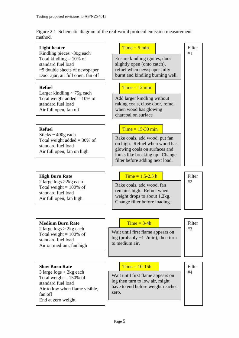
As such, the real-world protocol included measuring emissions during the lighting of a heater from cold, the addition of larger logs and then use of high burn rate (intended to simulate someone lighting the heater then running with high heat output to warm the living room quickly). As the fire began to die , additional large logs were added and the heater was run on medium (to simulate keeping the now-warm living room hot). Finally, the firebox was filled with a large load of larger logs and the air control set to slow burn-rate to simulate an over-night burn. Separate emission measurements were made for each of the light-up, high, medium and slow burn rates. The protocol is shown schematically in Figure 2.1. Appendix 1 includes photographs of fuel loads used in the real-world testing. All four heaters were tested to the real-world protocol and two of the heater models were also tested after they had been fitted with automatic combustion air control devices.
2.4 Shortened Test Methods In order to complete the range of testing in the time available2, it was necessary to reduce the number of repeat tests from three to two for three of the four heaters tested. The standard test method (AS/NZS4013) requires considerable appliance and calorimeter room preparation before commencing formal emission tests. Firstly, the appliance is lit and refuelled regularly to heat the calorimeter room and to build up a suitable base of hot charcoal in the firebox (warm-up). This typically takes two to three hours for medium and low burn-rate tests. The temperature (particularly flue temperature), power and charcoal weight must be manipulated so that they are close to the anticipated conditions at the end of a formal emission test cycle. Getting these conditions correct is important if the pre-burn cycle is to meet the requirements of the standard. Once conditions are considered satisfactory, the pre-test burn cycle can commence. This uses a standard fuel load and is conducted as if a formal test cycle was underway, except that emissions are not measured. At the end of the pre-test burn cycle, the first of the three emission test cycles begins. For medium burn rates, where cycle times are usually 3 to 4 hours, the emission test cycles commence mid-afternoon and run through to 3 or 4am the next day. For low burn rates, the tests only end the following morning. It is impossible to continue this type of testing day after day without two or three shifts of laboratory staff to share the load. The AHHA laboratory, however, is operated by just one person, so it was critical to arrange this research test program so that as many results for different heaters and variations of method and appliance could be obtained in a limited time.
2 The emission tests were performed in a commercial laboratory. Project funding allowed for 10 weeks of tests, although an additional week was funded due to some unavoidable requirements for additional testing of three of the heater models.
Page 4
Testing proposed revisions to AS/NZS4013
Figure 2.1 Schematic diagram of the real-world protocol emission measurement method.
Light heater Kindling pieces ~30g each Total kindling = 10% of standard fuel load ~5 double sheets of newspaper Door ajar, air full open, fan off
Ensure kindling ignites, door slightly open (onto catch), refuel when newspaper fully burnt and kindling burning well.
Time = 5 min Filter #1
Refuel Larger kindling ~ 75g each Total weight added = 10% of standard fuel load Air full open, fan off
Add larger kindling without raking coals, close door, refuel when wood has glowing charcoal on surface
Time = 12 min
Refuel Sticks ~ 400g each Total weight added = 30% of standard fuel load Air full open, fan on high
Rake coals, add wood, put fan on high. Refuel when wood has glowing coals on surfaces and looks like breaking up. Change filter before adding next load.
Time = 15-30 min
High Burn Rate 2 large logs >2kg each Total weight = 100% of standard fuel load Air full open, fan high
Rake coals, add wood, fan remains high. Refuel when weight drops to about 1.2kg. Change filter before loading.
Time = 1.5-2.5 h Filter #2
Medium Burn Rate 2 large logs > 2kg each Total weight = 100% of standard fuel load Air on medium, fan high
Wait until first flame appears on log (probably ~1-2min), then turn to medium air.
Time = 3-4h Filter #3
Slow Burn Rate 3 large logs > 2kg each Total weight = 150% of standard fuel load Air to low when flame visible, fan off End at zero weight
Wait until first flame appears on log then turn to low air, might have to end before weight reaches zero.
Time = 10-15h Filter #4
Page 5
Testing proposed revisions to AS/NZS4013
The approach adopted was to spend more time getting conditions at the end of the warm-up period as close to anticipated conditions at the end of a standard cycle. This was achieved through the experience gained in the laboratory by the researchers after many hundreds of tests over many years. The usual pre-test burn cycle was then used as the first emission cycle (i.e. emissions were collected) and this was followed with one normal emission cycle. The data (provided in the appendices) shows that the two cycles usually gave consistent results, certainly adequate for identifying the significant differences between appliances and test methods required for this research. 2.5 Heater Modifications The project brief requires an assessment of how the heater models used in this research might be modified to achieve emission factors of 4g/kg or less when tested to the revised method. Since the difference between the AS/NZS4013 method and the revised method is simply the earlier turn-down after refuelling, one obvious modification would be to attach an automatic device to supply additional combustion air for a short period after refuelling to simulate the normal AS/NZS4013 operation. But several other options are also possible. These are briefly discussed below. 2.5.1 Increased minimum air Laboratory testing and experience with woodheater use in general shows that a heater will smoke excessively if a load of fuel is added to a hot firebox and then fails to ignite (i.e. it smoulders without vigorous flame). This inevitably happens when there is little primary combustion air available (e.g. if the primary combustion air is set to a very low air input immediately after adding the fuel). Provided there is sufficient primary combustion air to quickly produce and sustain a visible flame, the heater will burn with considerably lower emissions. The precise air setting at which this happens requires considerable trial and error type testing. If too much air is added, the heater burns relatively cleanly but the operator cannot achieve lower heat outputs or extended intervals between refuelling. If too little air is added, the heater will smoke excessively. By trading off the burn-cycle time (i.e. accepting shorter burn periods) it should be possible to achieve emission factors below 4g/kg for the revised test method by increasing the minimum air supply for most heater models. This hypothesis was supported by one of the heater models tested (the smallest heater) because it passed the revised method without modification (i.e. there was sufficient minimum primary air on the low setting to maintain adequate combustion conditions straight after refuelling). It is possible3 that larger heaters will be more difficult to modify using this approach. However, the test results, discussed below, confirm that larger heaters could pass the revised method by increasing minimum air supply because all four heaters achieved emission factors less than 4g/kg for the medium burn rates. 2.5.2 Timer controlled air supply As mentioned above, a timed additional combustion air supply offers an obvious means of overcoming the problem of immediately turning down the manual air controls. Many variations of this idea are possible. The control could be mechanical
3 This was not tested during this research. It is an opinion shared by the authors, based on their experience with woodheater testing.
Page 6
Testing proposed revisions to AS/NZS4013
(as trialled here) or electrical. It would most likely be triggered by the opening and closing of the fuel-loading door, but it could include over-ride features if the air control is set on high burn. The automatic control might simply prevent the operator setting the air control to medium or low for a set period (considered impractical because consumers would probably find this very annoying). Or the control could simply delay the effective outcome of the control adjustments (the consumer would set the control when refuelling and the timer would delay the adjustment of combustion air for a set period). The timer could control an additional air supply to which the householder does not have access. This extra air supply could be admitted to the combustion chamber through the normal primary air system, or it could be separate from that system. In this research, the simplest approach was used, with a door-triggered mechanical timer admitting additional air through the normal primary air pre-heating system. As this research progressed, it became apparent that an automatic air control introduced a whole new set of variables that manufacturers could use to fine-tune heat output and emissions. The key variables are:
• The amount of air added through the automatic controls; • The time after door closing that the extra air was supplied; • The rate at which the extra air was shut off (it could be cut off suddenly, or
gradually reduced over a period of several minutes). For this research, an arbitrary (in the sense that alternatives were not tested) supplementary air supply was fitted. The cross-section of the supplementary air opening was equal to the difference between the cross-sections of air settings for high and medium burn rates. This meant that if the heater controls were set on medium, the device would allow the equivalent of high burn-rate combustion air until the timer shut the extra air off. However, it meant that if the manual combustion air control was turned to low, the total combustion air would be somewhere between medium and high, rather than high as in the normal AS/NZS4013 tests. Two timer-settings were tried on one heater model (10 minutes and 20 minutes). The 10-minute setting seemed too short, leading to poor ignition for low burn. The other heater that was modified incorporated a 20-minute timer setting. Further investigation by the industry, or by researchers, is needed to assess the potential for improved performance and reduced emissions through the use of automatic, timed combustion air supplies. 2.5.3 Temperature controlled air supply Rather than relying on time delays, the temperature of the appliance could be used to control combustion air. A device that senses the temperature on a section of the firebox and then reduces the air supply to medium or low settings once a set temperature is reached could be used. The use of temperature sensors (often bi-metal strips) to automatically control combustion air is not new. Heaters with this feature have been available in Australia and New Zealand for several decades. But few models now available include temperature controlled combustion air supplies because as a heater cools during an over-night burn the combustion air increases, thus significantly shortening the burn time.
Page 7
Testing proposed revisions to AS/NZS4013
However, a New Zealand manufacturer has recently put a simple mechanical device on the market that delays closing down the combustion air until the heater is hot, but does not open the air supply again as the heater cools unless the fuel-loading door is opened. The manufacturer of this device, Werner Janssens4, claims that it can easily be fitted to many heater models, it is cheap and it is robust. This device was not available for testing as part of this research, but it looks promising and might prove a practical alternative to a timer-based automatic control. 2.5.4 Flue draft controlled air supply Combustion conditions have a strong influence on flue draft. Use of flue draft to close an air supply opened when the fuel-loading door is opened would be simple, cheap and robust. For these reasons, flue draft was monitored as part of this research to see if it was practical to develop a draft-controlled device to reduce emissions. The research indicated that flue draft is not suited to automatic control of combustion air. The reason was that the draft increased very rapidly as soon as flame was present in the firebox and then levelled off at a fairly steady value. This mean that if draft was used to trigger the closing of a supplementary air supply, it would close within a few minutes of adding a new fuel load, rather than the 15 to 20 minutes that seems appropriate. 2.5.5 Improved secondary air In the United States, the test method for woodheaters does not allow a period of high burn-rate before medium and low burn-rates. Manufacturers have used more sophisticated secondary air systems than are common in Australian or New Zealand heater models to deal with this aspect of test procedures. It would have been valuable to test some US approved heater models to the revised test method to see how they perform. However, this was not done as part of this research. 2.5.6 International developments It appears that at least two overseas companies5 are fitting some heater models with automatic controls designed to minimise smoke emissions through control of combustion air. Only limited information about these appliances has been obtained during this research project, but investigations are continuing.
4 Werner Janssens is the Managing Director of West Glen Industries Ltd, PO Box 20-443 GLEN EDEN, Auckland, New Zealand. Mr Janssens holds a patent application on the device. He has circulated a description of the device quite widely within the wood heating industry. At the time of writing this report, it is not known if any commercially available heaters are fitted with the device. 5 The US heater manufacturer Quadrafire (www.quadrafire.com) reports on its low emission technology referring to controls that make sure the fire is well established before automatically adjusting the controls to the desired heat output. The Belgian heater manufacturer Nestor Martin (www.nestormartin.com) reports an award winning design in their “Woodbox” heater that automatically ensures good combustion.
Page 8
Testing proposed revisions to AS/NZS4013
3 Results This section is divided into five sub-sections with the first four sub-sections providing a description of each of the four heaters and a summary of each heater’s emission and performance results. The fifth sub-section provides summary tables comparing the results for the four heaters. It should be noted that each heater model performs quite differently, so any generalisation of the results should be treated with caution. 3.1 Heater A Heater A was a small, freestanding, convection woodheater. Its main design features are summarised in Box 3.1. This heater achieved an emission factor less than 4g/kg when tested to both the present standard method and the revised test method, so no modifications of the heater were attempted. Three sets of emission tests were carried out: the AS/NZS4013 standard test, the revised test and the real-world protocol test. Results are summarised in Tables 3.1 and 3.2. More details of the test results for Heater A are provided in Appendix 2.
Box 3.1 Heater A Description
Freestanding Model Convection design heater with 3-speed fan
Small heater (firebox volume 32L, AS/NZS4013 fuel test load 5.2kg) Solid base (i.e. no grate); firebrick on base Cast iron liners (sides and rear) Steel baffle plate Primary air entering above door, slide air control Secondary air entering through perforated tube at rear of firebox just below
baffle with external preheating chamber on sides of firebox Ceramic-glass panel in door The significant points to note in terms of emissions (Table 3.1) for this heater are:
• The AS/NZS4013 emission test result of 1.8g/kg places this heater in the cleaner-burning group of compliant heaters (i.e. it has a low emission factor).
• The emission factor measured using the proposed test method was approximately double the AS/NZS4013 emission factor, but still <4g/kg.
• The real-world emission factor averaged 5.9g/kg with both days of testing giving similar results. This was about 3.3 times the AS/NZS4013 result and 1.7 times the revised method result.
• The emission rates for the AS/NZS4013 high, medium and low tests were similar. For the revised test method, the emission rates for medium and low were approximately double the standard test rates (i.e. a similar ratio to the emission factors). The emission rates for the real-world tests are discussed below.
Page 9
Testing proposed revisions to AS/NZS4013
Table 3.1
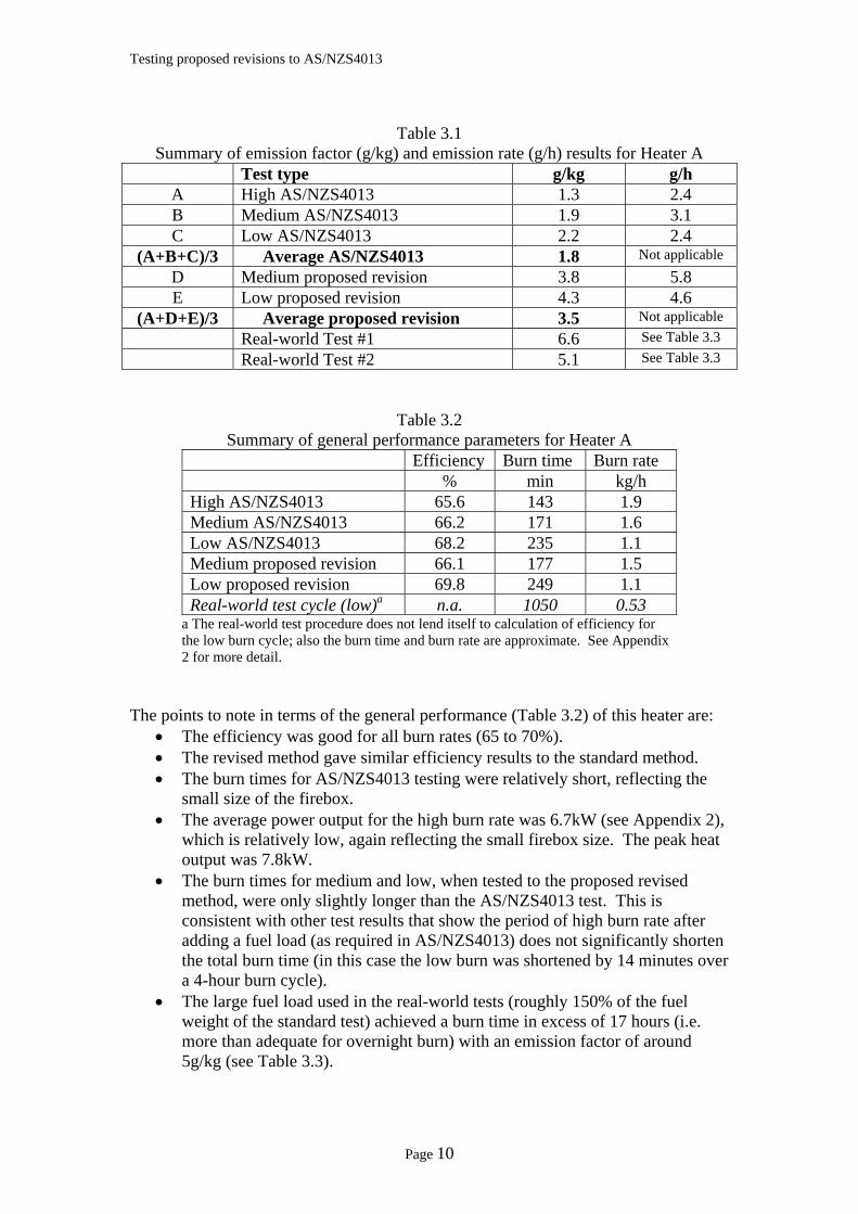
Summary of emission factor (g/kg) and emission rate (g/h) results for Heater A Test type g/kg g/h
A High AS/NZS4013 1.3 2.4 B Medium AS/NZS4013 1.9 3.1 C Low AS/NZS4013 2.2 2.4
(A+B+C)/3 Average AS/NZS4013 1.8 Not applicable D Medium proposed revision 3.8 5.8 E Low proposed revision 4.3 4.6
(A+D+E)/3 Average proposed revision 3.5 Not applicable Real-world Test #1 6.6 See Table 3.3 Real-world Test #2 5.1 See Table 3.3
Table 3.2 Summary of general performance parameters for Heater A
Efficiency Burn time Burn rate % min kg/h
High AS/NZS4013 65.6 143 1.9 Medium AS/NZS4013 66.2 171 1.6 Low AS/NZS4013 68.2 235 1.1 Medium proposed revision 66.1 177 1.5 Low proposed revision 69.8 249 1.1 Real-world test cycle (low)a n.a. 1050 0.53
a The real-world test procedure does not lend itself to calculation of efficiency for the low burn cycle; also the burn time and burn rate are approximate. See Appendix 2 for more detail.
The points to note in terms of the general performance (Table 3.2) of this heater are:
• The efficiency was good for all burn rates (65 to 70%). • The revised method gave similar efficiency results to the standard method. • The burn times for AS/NZS4013 testing were relatively short, reflecting the
small size of the firebox. • The average power output for the high burn rate was 6.7kW (see Appendix 2),
which is relatively low, again reflecting the small firebox size. The peak heat output was 7.8kW.
• The burn times for medium and low, when tested to the proposed revised method, were only slightly longer than the AS/NZS4013 test. This is consistent with other test results that show the period of high burn rate after adding a fuel load (as required in AS/NZS4013) does not significantly shorten the total burn time (in this case the low burn was shortened by 14 minutes over a 4-hour burn cycle).
• The large fuel load used in the real-world tests (roughly 150% of the fuel weight of the standard test) achieved a burn time in excess of 17 hours (i.e. more than adequate for overnight burn) with an emission factor of around 5g/kg (see Table 3.3).
Page 10
Testing proposed revisions to AS/NZS4013
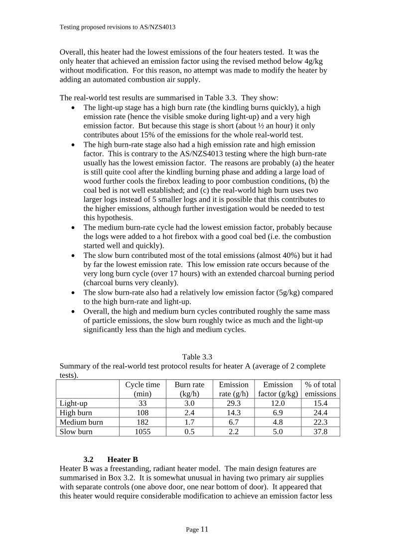
Overall, this heater had the lowest emissions of the four heaters tested. It was the only heater that achieved an emission factor using the revised method below 4g/kg without modification. For this reason, no attempt was made to modify the heater by adding an automated combustion air supply. The real-world test results are summarised in Table 3.3. They show:
• The light-up stage has a high burn rate (the kindling burns quickly), a high emission rate (hence the visible smoke during light-up) and a very high emission factor. But because this stage is short (about ½ an hour) it only contributes about 15% of the emissions for the whole real-world test.
• The high burn-rate stage also had a high emission rate and high emission factor. This is contrary to the AS/NZS4013 testing where the high burn-rate usually has the lowest emission factor. The reasons are probably (a) the heater is still quite cool after the kindling burning phase and adding a large load of wood further cools the firebox leading to poor combustion conditions, (b) the coal bed is not well established; and (c) the real-world high burn uses two larger logs instead of 5 smaller logs and it is possible that this contributes to the higher emissions, although further investigation would be needed to test this hypothesis.
• The medium burn-rate cycle had the lowest emission factor, probably because the logs were added to a hot firebox with a good coal bed (i.e. the combustion started well and quickly).
• The slow burn contributed most of the total emissions (almost 40%) but it had by far the lowest emission rate. This low emission rate occurs because of the very long burn cycle (over 17 hours) with an extended charcoal burning period (charcoal burns very cleanly).
• The slow burn-rate also had a relatively low emission factor (5g/kg) compared to the high burn-rate and light-up.
• Overall, the high and medium burn cycles contributed roughly the same mass of particle emissions, the slow burn roughly twice as much and the light-up significantly less than the high and medium cycles.
Table 3.3 Summary of the real-world test protocol results for heater A (average of 2 complete tests).
Cycle time (min)
Burn rate (kg/h)
Emission rate (g/h)
Emission factor (g/kg)
% of total emissions
Light-up 33 3.0 29.3 12.0 15.4 High burn 108 2.4 14.3 6.9 24.4 Medium burn 182 1.7 6.7 4.8 22.3 Slow burn 1055 0.5 2.2 5.0 37.8
3.2 Heater B Heater B was a freestanding, radiant heater model. The main design features are summarised in Box 3.2. It is somewhat unusual in having two primary air supplies with separate controls (one above door, one near bottom of door). It appeared that this heater would require considerable modification to achieve an emission factor less
Page 11
Testing proposed revisions to AS/NZS4013
than 4g/kg using the revised test method. Time and resource limitations meant that modifications were not attempted. The heater was tested using the same three test methods as Heater A, namely to AS/NZS4013, to the revised test method and to the real-world protocol. The results are summarised in Tables 3.4 and 3.5. More details of the results for Heater B are presented in Appendix 3.
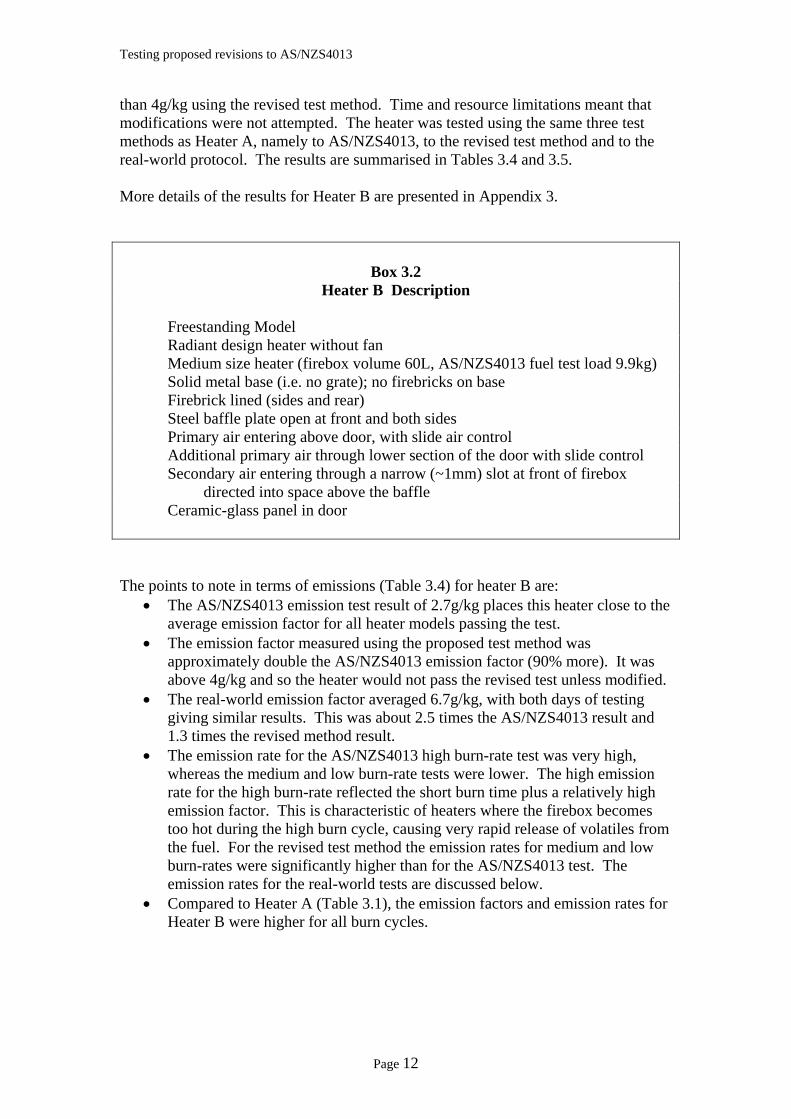
Box 3.2 Heater B Description
Freestanding Model Radiant design heater without fan
Medium size heater (firebox volume 60L, AS/NZS4013 fuel test load 9.9kg) Solid metal base (i.e. no grate); no firebricks on base Firebrick lined (sides and rear) Steel baffle plate open at front and both sides Primary air entering above door, with slide air control Additional primary air through lower section of the door with slide control Secondary air entering through a narrow (~1mm) slot at front of firebox
directed into space above the baffle Ceramic-glass panel in door The points to note in terms of emissions (Table 3.4) for heater B are:
• The AS/NZS4013 emission test result of 2.7g/kg places this heater close to the average emission factor for all heater models passing the test.
• The emission factor measured using the proposed test method was approximately double the AS/NZS4013 emission factor (90% more). It was above 4g/kg and so the heater would not pass the revised test unless modified.
• The real-world emission factor averaged 6.7g/kg, with both days of testing giving similar results. This was about 2.5 times the AS/NZS4013 result and 1.3 times the revised method result.
• The emission rate for the AS/NZS4013 high burn-rate test was very high, whereas the medium and low burn-rate tests were lower. The high emission rate for the high burn-rate reflected the short burn time plus a relatively high emission factor. This is characteristic of heaters where the firebox becomes too hot during the high burn cycle, causing very rapid release of volatiles from the fuel. For the revised test method the emission rates for medium and low burn-rates were significantly higher than for the AS/NZS4013 test. The emission rates for the real-world tests are discussed below.
• Compared to Heater A (Table 3.1), the emission factors and emission rates for Heater B were higher for all burn cycles.
Page 12
Testing proposed revisions to AS/NZS4013
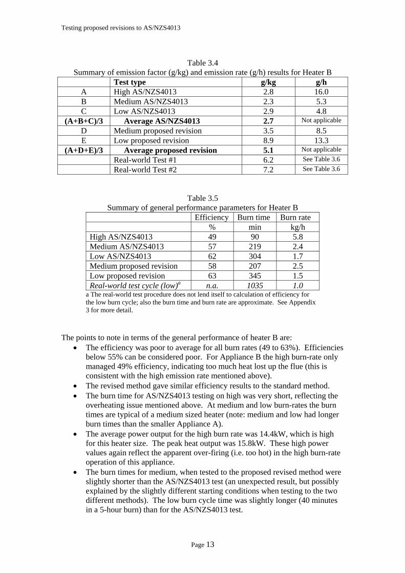
Table 3.4
Summary of emission factor (g/kg) and emission rate (g/h) results for Heater B Test type g/kg g/h
A High AS/NZS4013 2.8 16.0 B Medium AS/NZS4013 2.3 5.3 C Low AS/NZS4013 2.9 4.8
(A+B+C)/3 Average AS/NZS4013 2.7 Not applicable D Medium proposed revision 3.5 8.5 E Low proposed revision 8.9 13.3
(A+D+E)/3 Average proposed revision 5.1 Not applicable Real-world Test #1 6.2 See Table 3.6 Real-world Test #2 7.2 See Table 3.6
Table 3.5 Summary of general performance parameters for Heater B
Efficiency Burn time Burn rate % min kg/h
High AS/NZS4013 49 90 5.8 Medium AS/NZS4013 57 219 2.4 Low AS/NZS4013 62 304 1.7 Medium proposed revision 58 207 2.5 Low proposed revision 63 345 1.5 Real-world test cycle (low)a n.a. 1035 1.0
a The real-world test procedure does not lend itself to calculation of efficiency for the low burn cycle; also the burn time and burn rate are approximate. See Appendix 3 for more detail.
The points to note in terms of the general performance of heater B are:
• The efficiency was poor to average for all burn rates (49 to 63%). Efficiencies below 55% can be considered poor. For Appliance B the high burn-rate only managed 49% efficiency, indicating too much heat lost up the flue (this is consistent with the high emission rate mentioned above).
• The revised method gave similar efficiency results to the standard method. • The burn time for AS/NZS4013 testing on high was very short, reflecting the
overheating issue mentioned above. At medium and low burn-rates the burn times are typical of a medium sized heater (note: medium and low had longer burn times than the smaller Appliance A).
• The average power output for the high burn rate was 14.4kW, which is high for this heater size. The peak heat output was 15.8kW. These high power values again reflect the apparent over-firing (i.e. too hot) in the high burn-rate operation of this appliance.
• The burn times for medium, when tested to the proposed revised method were slightly shorter than the AS/NZS4013 test (an unexpected result, but possibly explained by the slightly different starting conditions when testing to the two different methods). The low burn cycle time was slightly longer (40 minutes in a 5-hour burn) than for the AS/NZS4013 test.
Page 13
Testing proposed revisions to AS/NZS4013
• The large fuel load used in the real-world tests (roughly 150% of the fuel weight of the standard test) achieved a burn time in excess of 17 hours (i.e. more than adequate for overnight burn) with an emission factor of around 10g/kg (see Table 3.6).
The distinguishing feature of this heater’s performance was the low efficiency and high emission rate for the high burn cycle. When tested to the proposed revised method it achieved the second best emission factor (5.1g/kg), but exceeded 4g/kg. The design of the heater meant that a simple timer-driven automatic control would have been difficult to add to the heater. This meant that no modifications were attempted to see if it would pass the revised test method. It might have been possible to achieve an average emission factor less than 4g/kg using the revised test method by increasing the minimum air supply. Unfortunately, the time available for use of the laboratory was insufficient to attempt this modification. The real-world test results for heater B are summarised in Table 3.6. They show:
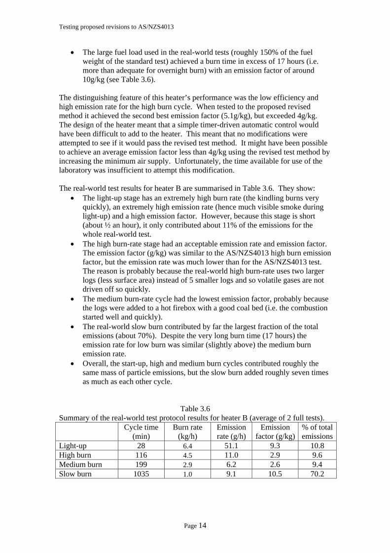
• The light-up stage has an extremely high burn rate (the kindling burns very quickly), an extremely high emission rate (hence much visible smoke during light-up) and a high emission factor. However, because this stage is short (about ½ an hour), it only contributed about 11% of the emissions for the whole real-world test.
• The high burn-rate stage had an acceptable emission rate and emission factor. The emission factor (g/kg) was similar to the AS/NZS4013 high burn emission factor, but the emission rate was much lower than for the AS/NZS4013 test. The reason is probably because the real-world high burn-rate uses two larger logs (less surface area) instead of 5 smaller logs and so volatile gases are not driven off so quickly.
• The medium burn-rate cycle had the lowest emission factor, probably because the logs were added to a hot firebox with a good coal bed (i.e. the combustion started well and quickly).
• The real-world slow burn contributed by far the largest fraction of the total emissions (about 70%). Despite the very long burn time (17 hours) the emission rate for low burn was similar (slightly above) the medium burn emission rate.
• Overall, the start-up, high and medium burn cycles contributed roughly the same mass of particle emissions, but the slow burn added roughly seven times as much as each other cycle.
Table 3.6 Summary of the real-world test protocol results for heater B (average of 2 full tests).
Cycle time (min)
Burn rate (kg/h)
Emission rate (g/h)
Emission factor (g/kg)
% of total emissions
Light-up 28 6.4 51.1 9.3 10.8 High burn 116 4.5 11.0 2.9 9.6 Medium burn 199 2.9 6.2 2.6 9.4 Slow burn 1035 1.0 9.1 10.5 70.2
Page 14
Testing proposed revisions to AS/NZS4013
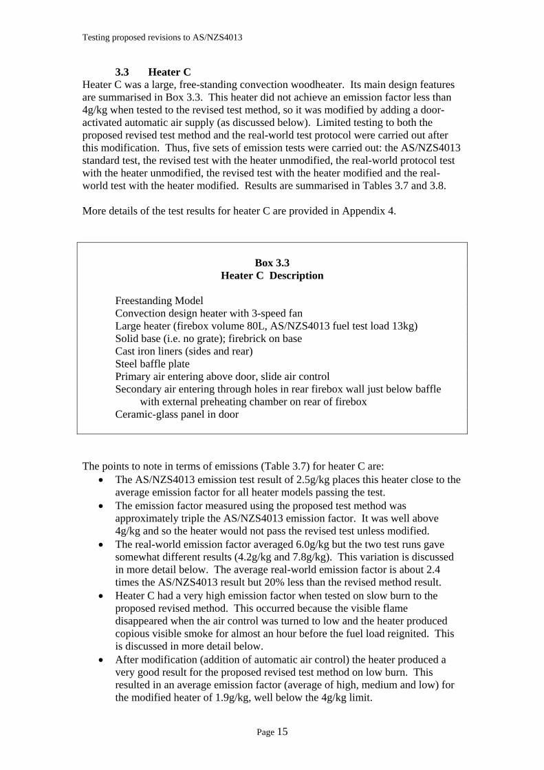
3.3 Heater C Heater C was a large, free-standing convection woodheater. Its main design features are summarised in Box 3.3. This heater did not achieve an emission factor less than 4g/kg when tested to the revised test method, so it was modified by adding a door-activated automatic air supply (as discussed below). Limited testing to both the proposed revised test method and the real-world test protocol were carried out after this modification. Thus, five sets of emission tests were carried out: the AS/NZS4013 standard test, the revised test with the heater unmodified, the real-world protocol test with the heater unmodified, the revised test with the heater modified and the real-world test with the heater modified. Results are summarised in Tables 3.7 and 3.8. More details of the test results for heater C are provided in Appendix 4.
Box 3.3 Heater C Description
Freestanding Model Convection design heater with 3-speed fan
Large heater (firebox volume 80L, AS/NZS4013 fuel test load 13kg) Solid base (i.e. no grate); firebrick on base Cast iron liners (sides and rear) Steel baffle plate Primary air entering above door, slide air control Secondary air entering through holes in rear firebox wall just below baffle
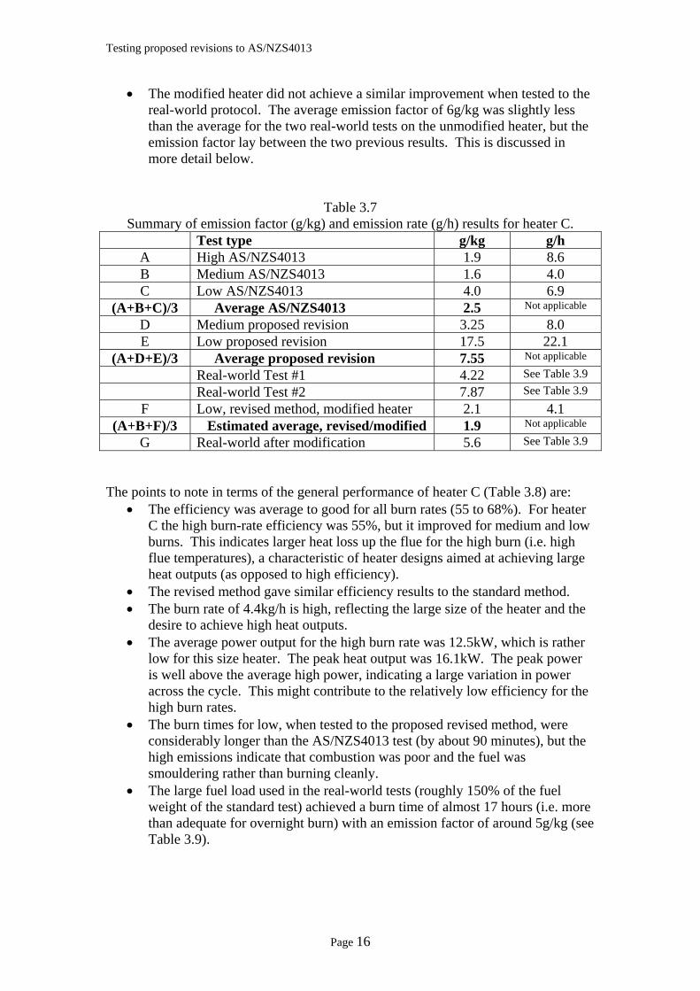
with external preheating chamber on rear of firebox Ceramic-glass panel in door The points to note in terms of emissions (Table 3.7) for heater C are:
• The AS/NZS4013 emission test result of 2.5g/kg places this heater close to the average emission factor for all heater models passing the test.
• The emission factor measured using the proposed test method was approximately triple the AS/NZS4013 emission factor. It was well above 4g/kg and so the heater would not pass the revised test unless modified.
• The real-world emission factor averaged 6.0g/kg but the two test runs gave somewhat different results (4.2g/kg and 7.8g/kg). This variation is discussed in more detail below. The average real-world emission factor is about 2.4 times the AS/NZS4013 result but 20% less than the revised method result.
• Heater C had a very high emission factor when tested on slow burn to the proposed revised method. This occurred because the visible flame disappeared when the air control was turned to low and the heater produced copious visible smoke for almost an hour before the fuel load reignited. This is discussed in more detail below.
• After modification (addition of automatic air control) the heater produced a very good result for the proposed revised test method on low burn. This resulted in an average emission factor (average of high, medium and low) for the modified heater of 1.9g/kg, well below the 4g/kg limit.
Page 15
Testing proposed revisions to AS/NZS4013
• The modified heater did not achieve a similar improvement when tested to the real-world protocol. The average emission factor of 6g/kg was slightly less than the average for the two real-world tests on the unmodified heater, but the emission factor lay between the two previous results. This is discussed in more detail below.
Table 3.7 Summary of emission factor (g/kg) and emission rate (g/h) results for heater C.
Test type g/kg g/h A High AS/NZS4013 1.9 8.6 B Medium AS/NZS4013 1.6 4.0 C Low AS/NZS4013 4.0 6.9
(A+B+C)/3 Average AS/NZS4013 2.5 Not applicable
D Medium proposed revision 3.25 8.0 E Low proposed revision 17.5 22.1
(A+D+E)/3 Average proposed revision 7.55 Not applicable Real-world Test #1 4.22 See Table 3.9 Real-world Test #2 7.87 See Table 3.9
F Low, revised method, modified heater 2.1 4.1 (A+B+F)/3 Estimated average, revised/modified 1.9 Not applicable
G Real-world after modification 5.6 See Table 3.9 The points to note in terms of the general performance of heater C (Table 3.8) are:
• The efficiency was average to good for all burn rates (55 to 68%). For heater C the high burn-rate efficiency was 55%, but it improved for medium and low burns. This indicates larger heat loss up the flue for the high burn (i.e. high flue temperatures), a characteristic of heater designs aimed at achieving large heat outputs (as opposed to high efficiency).
• The revised method gave similar efficiency results to the standard method. • The burn rate of 4.4kg/h is high, reflecting the large size of the heater and the
desire to achieve high heat outputs. • The average power output for the high burn rate was 12.5kW, which is rather
low for this size heater. The peak heat output was 16.1kW. The peak power is well above the average high power, indicating a large variation in power across the cycle. This might contribute to the relatively low efficiency for the high burn rates.
• The burn times for low, when tested to the proposed revised method, were considerably longer than the AS/NZS4013 test (by about 90 minutes), but the high emissions indicate that combustion was poor and the fuel was smouldering rather than burning cleanly.
• The large fuel load used in the real-world tests (roughly 150% of the fuel weight of the standard test) achieved a burn time of almost 17 hours (i.e. more than adequate for overnight burn) with an emission factor of around 5g/kg (see Table 3.9).
Page 16
Testing proposed revisions to AS/NZS4013
Table 3.8 Summary of general performance parameters for heater C
Efficiency Burn time Burn rate % min kg/h
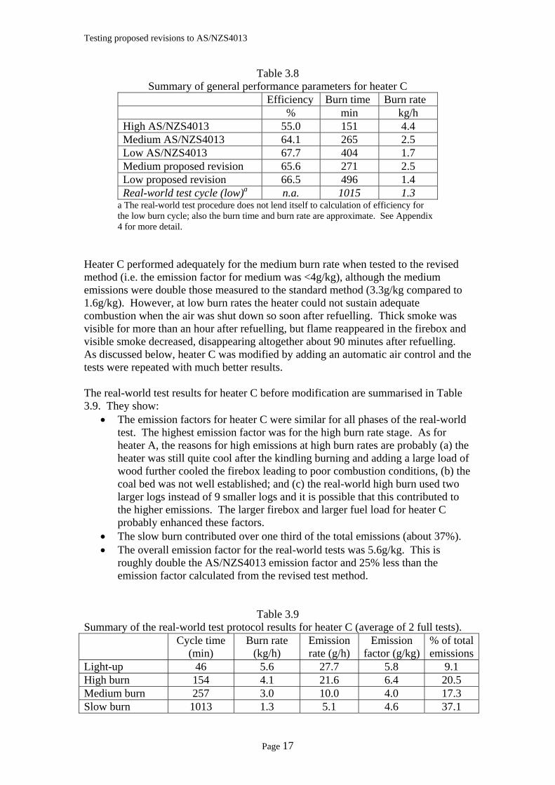
High AS/NZS4013 55.0 151 4.4 Medium AS/NZS4013 64.1 265 2.5 Low AS/NZS4013 67.7 404 1.7 Medium proposed revision 65.6 271 2.5 Low proposed revision 66.5 496 1.4 Real-world test cycle (low)a n.a. 1015 1.3
a The real-world test procedure does not lend itself to calculation of efficiency for the low burn cycle; also the burn time and burn rate are approximate. See Appendix 4 for more detail.
Heater C performed adequately for the medium burn rate when tested to the revised method (i.e. the emission factor for medium was <4g/kg), although the medium emissions were double those measured to the standard method (3.3g/kg compared to 1.6g/kg). However, at low burn rates the heater could not sustain adequate combustion when the air was shut down so soon after refuelling. Thick smoke was visible for more than an hour after refuelling, but flame reappeared in the firebox and visible smoke decreased, disappearing altogether about 90 minutes after refuelling. As discussed below, heater C was modified by adding an automatic air control and the tests were repeated with much better results. The real-world test results for heater C before modification are summarised in Table 3.9. They show:
• The emission factors for heater C were similar for all phases of the real-world test. The highest emission factor was for the high burn rate stage. As for heater A, the reasons for high emissions at high burn rates are probably (a) the heater was still quite cool after the kindling burning and adding a large load of wood further cooled the firebox leading to poor combustion conditions, (b) the coal bed was not well established; and (c) the real-world high burn used two larger logs instead of 9 smaller logs and it is possible that this contributed to the higher emissions. The larger firebox and larger fuel load for heater C probably enhanced these factors.
• The slow burn contributed over one third of the total emissions (about 37%). • The overall emission factor for the real-world tests was 5.6g/kg. This is
roughly double the AS/NZS4013 emission factor and 25% less than the emission factor calculated from the revised test method.
Table 3.9 Summary of the real-world test protocol results for heater C (average of 2 full tests).
Cycle time (min)
Burn rate (kg/h)
Emission rate (g/h)
Emission factor (g/kg)
% of total emissions
Light-up 46 5.6 27.7 5.8 9.1 High burn 154 4.1 21.6 6.4 20.5 Medium burn 257 3.0 10.0 4.0 17.3 Slow burn 1013 1.3 5.1 4.6 37.1
Page 17
Testing proposed revisions to AS/NZS4013
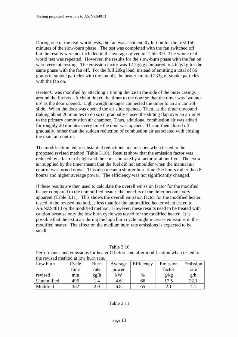
During one of the real-world tests, the fan was accidentally left on for the first 150 minutes of the slow-burn phase. The test was completed with the fan switched off, but the results were not included in the averages given in Table 3.9. The whole real-world test was repeated. However, the results for the slow-burn phase with the fan on were very interesting. The emission factor was 12.2g/kg compared to 4.62g/kg for the same phase with the fan off. For the full 20kg load, instead of emitting a total of 86 grams of smoke particles with the fan off, the heater emitted 233g of smoke particles with the fan on. Heater C was modified by attaching a timing device to the side of the outer casings around the firebox. A chain linked the timer to the door so that the timer was ‘wound-up’ as the door opened. Light-weigh linkages connected the timer to an air control slide. When the door was opened the air slide opened. Then, as the timer unwound (taking about 20 minutes to do so) it gradually closed the sliding flap over an air inlet to the primary combustion air chamber. Thus, additional combustion air was added for roughly 20 minutes every time the door was opened. The air then closed off gradually, rather than the sudden reduction of combustion air associated with closing the main air control. The modification led to substantial reductions in emissions when tested to the proposed revised method (Table 3.10). Results show that the emission factor was reduced by a factor of eight and the emission rate by a factor of about five. The extra air supplied by the timer meant that the fuel did not smoulder when the manual air control was turned down. This also meant a shorter burn time (5½ hours rather than 8 hours) and higher average power. The efficiency was not significantly changed. If these results are then used to calculate the overall emission factor for the modified heater compared to the unmodified heater, the benefits of the timer become very apparent (Table 3.11). This shows the overall emission factor for the modified heater, tested to the revised method, is less than for the unmodified heater when tested to AS/NZS4013 or the modified method. However, these results need to be treated with caution because only the low burn cycle was tested for the modified heater. It is possible that the extra air during the high burn cycle might increase emissions in the modified heater. The effect on the medium burn rate emissions is expected to be small.
Table 3.10 Performance and emissions for heater C before and after modification when tested to the revised method at low burn rate. Low burn Cycle
time Burn rate
Average power
Efficiency Emission factor
Emission rate
revised min kg/h kW % g/kg g/h Unmodified 496 1.4 4.6 66 17.5 22.1 Modified 332 2.0 6.8 65 2.1 4.1
Table 3.11
Page 18
Testing proposed revisions to AS/NZS4013
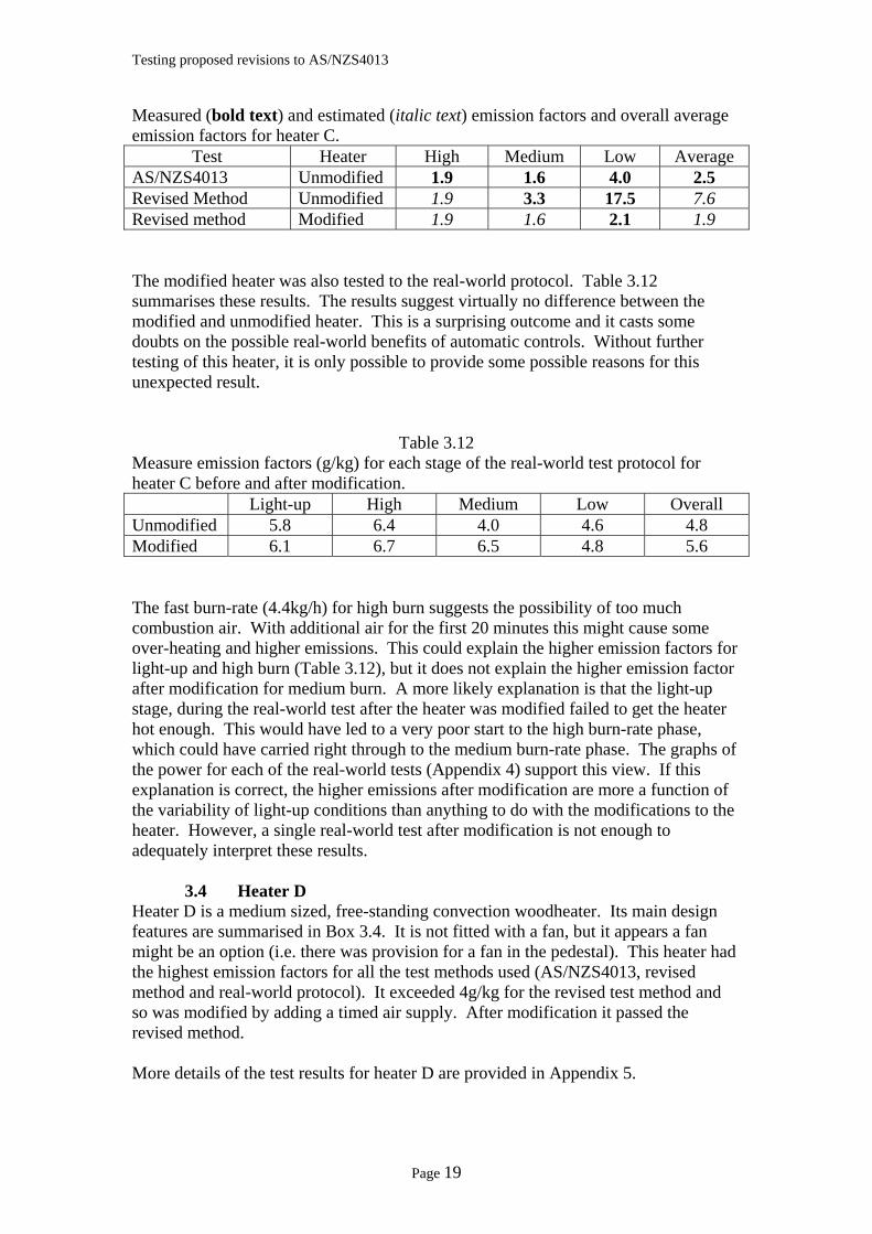
Measured (bold text) and estimated (italic text) emission factors and overall average emission factors for heater C.
Test Heater High Medium Low Average AS/NZS4013 Unmodified 1.9 1.6 4.0 2.5 Revised Method Unmodified 1.9 3.3 17.5 7.6 Revised method Modified 1.9 1.6 2.1 1.9 The modified heater was also tested to the real-world protocol. Table 3.12 summarises these results. The results suggest virtually no difference between the modified and unmodified heater. This is a surprising outcome and it casts some doubts on the possible real-world benefits of automatic controls. Without further testing of this heater, it is only possible to provide some possible reasons for this unexpected result.
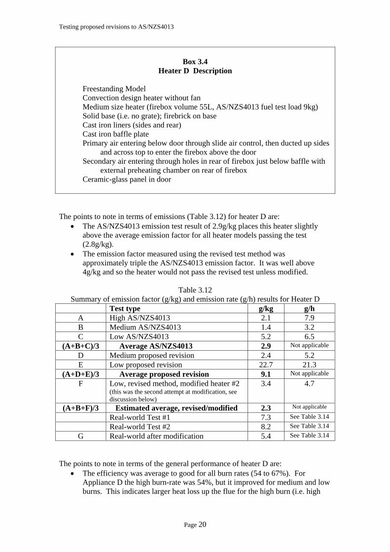
Table 3.12 Measure emission factors (g/kg) for each stage of the real-world test protocol for heater C before and after modification. Light-up High Medium Low Overall Unmodified 5.8 6.4 4.0 4.6 4.8 Modified 6.1 6.7 6.5 4.8 5.6 The fast burn-rate (4.4kg/h) for high burn suggests the possibility of too much combustion air. With additional air for the first 20 minutes this might cause some over-heating and higher emissions. This could explain the higher emission factors for light-up and high burn (Table 3.12), but it does not explain the higher emission factor after modification for medium burn. A more likely explanation is that the light-up stage, during the real-world test after the heater was modified failed to get the heater hot enough. This would have led to a very poor start to the high burn-rate phase, which could have carried right through to the medium burn-rate phase. The graphs of the power for each of the real-world tests (Appendix 4) support this view. If this explanation is correct, the higher emissions after modification are more a function of the variability of light-up conditions than anything to do with the modifications to the heater. However, a single real-world test after modification is not enough to adequately interpret these results. 3.4 Heater D Heater D is a medium sized, free-standing convection woodheater. Its main design features are summarised in Box 3.4. It is not fitted with a fan, but it appears a fan might be an option (i.e. there was provision for a fan in the pedestal). This heater had the highest emission factors for all the test methods used (AS/NZS4013, revised method and real-world protocol). It exceeded 4g/kg for the revised test method and so was modified by adding a timed air supply. After modification it passed the revised method. More details of the test results for heater D are provided in Appendix 5.
Page 19
Testing proposed revisions to AS/NZS4013
Box 3.4
Heater D Description Freestanding Model Convection design heater without fan
Medium size heater (firebox volume 55L, AS/NZS4013 fuel test load 9kg) Solid base (i.e. no grate); firebrick on base Cast iron liners (sides and rear) Cast iron baffle plate Primary air entering below door through slide air control, then ducted up sides
and across top to enter the firebox above the door Secondary air entering through holes in rear of firebox just below baffle with
external preheating chamber on rear of firebox Ceramic-glass panel in door The points to note in terms of emissions (Table 3.12) for heater D are:
• The AS/NZS4013 emission test result of 2.9g/kg places this heater slightly above the average emission factor for all heater models passing the test (2.8g/kg).
• The emission factor measured using the revised test method was approximately triple the AS/NZS4013 emission factor. It was well above 4g/kg and so the heater would not pass the revised test unless modified.
Table 3.12
Summary of emission factor (g/kg) and emission rate (g/h) results for Heater D Test type g/kg g/h
A High AS/NZS4013 2.1 7.9 B Medium AS/NZS4013 1.4 3.2 C Low AS/NZS4013 5.2 6.5
(A+B+C)/3 Average AS/NZS4013 2.9 Not applicable D Medium proposed revision 2.4 5.2 E Low proposed revision 22.7 21.3
(A+D+E)/3 Average proposed revision 9.1 Not applicable F Low, revised method, modified heater #2
(this was the second attempt at modification, see discussion below)
3.4 4.7
(A+B+F)/3 Estimated average, revised/modified 2.3 Not applicable Real-world Test #1 7.3 See Table 3.14 Real-world Test #2 8.2 See Table 3.14
G Real-world after modification 5.4 See Table 3.14 The points to note in terms of the general performance of heater D are:
• The efficiency was average to good for all burn rates (54 to 67%). For Appliance D the high burn-rate was 54%, but it improved for medium and low burns. This indicates larger heat loss up the flue for the high burn (i.e. high
Page 20
Testing proposed revisions to AS/NZS4013
flue temperatures), a characteristic of heater designs aimed at achieving large heat outputs (as opposed to high efficiency).
• The real-world emission factor averaged 7.8g/kg with the two test runs before modification producing similar results (7.3g/kg and 8.2g/kg). The average real-world emission factor was about 2.6 times the AS/NZS4013 result but 15% less than the revised method result.
• Heater D had a very high emission factor when tested on slow burn to the proposed revised method. This occurred because the visible flame disappeared when the air control was turned to low and the heater produced copious visible smoke for almost an hour before the load reignited.
• After modification (addition of automatic air control) the heater produced a good result for the proposed revised test method on low burn. This resulted in an average emission factor for the modified heater of 2.3/kg, well below the 4g/kg limit.
• The modified heater did not achieve as big an improvement when tested to the real-world protocol. The average emission factor of 5.4g/kg was 40% less than the average for the two real-world tests on the unmodified heater. This is discussed in more detail below.
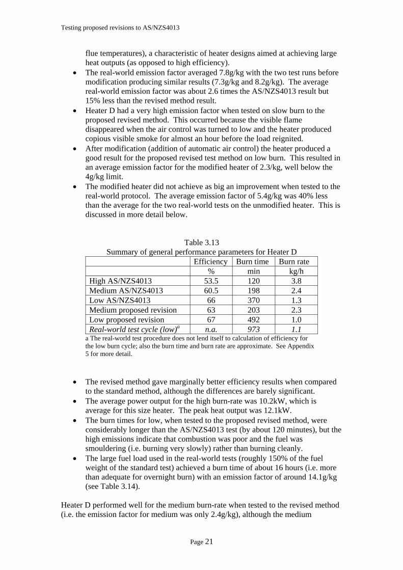
Table 3.13 Summary of general performance parameters for Heater D
Efficiency Burn time Burn rate % min kg/h
High AS/NZS4013 53.5 120 3.8 Medium AS/NZS4013 60.5 198 2.4 Low AS/NZS4013 66 370 1.3 Medium proposed revision 63 203 2.3 Low proposed revision 67 492 1.0 Real-world test cycle (low)a n.a. 973 1.1
a The real-world test procedure does not lend itself to calculation of efficiency for the low burn cycle; also the burn time and burn rate are approximate. See Appendix 5 for more detail.
• The revised method gave marginally better efficiency results when compared to the standard method, although the differences are barely significant.
• The average power output for the high burn-rate was 10.2kW, which is average for this size heater. The peak heat output was 12.1kW.
• The burn times for low, when tested to the proposed revised method, were considerably longer than the AS/NZS4013 test (by about 120 minutes), but the high emissions indicate that combustion was poor and the fuel was smouldering (i.e. burning very slowly) rather than burning cleanly.
• The large fuel load used in the real-world tests (roughly 150% of the fuel weight of the standard test) achieved a burn time of about 16 hours (i.e. more than adequate for overnight burn) with an emission factor of around 14.1g/kg (see Table 3.14).
Heater D performed well for the medium burn-rate when tested to the revised method (i.e. the emission factor for medium was only 2.4g/kg), although the medium
Page 21
Testing proposed revisions to AS/NZS4013
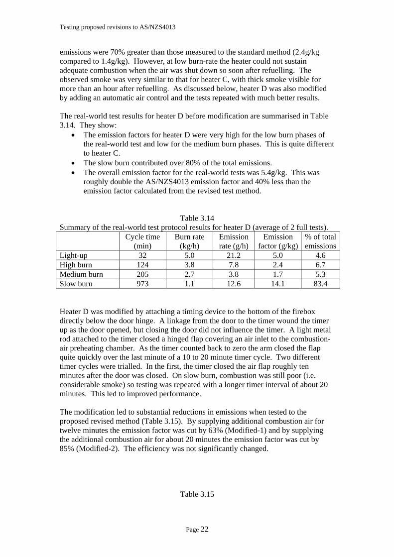
emissions were 70% greater than those measured to the standard method (2.4g/kg compared to 1.4g/kg). However, at low burn-rate the heater could not sustain adequate combustion when the air was shut down so soon after refuelling. The observed smoke was very similar to that for heater C, with thick smoke visible for more than an hour after refuelling. As discussed below, heater D was also modified by adding an automatic air control and the tests repeated with much better results. The real-world test results for heater D before modification are summarised in Table 3.14. They show:
• The emission factors for heater D were very high for the low burn phases of the real-world test and low for the medium burn phases. This is quite different to heater C.
• The slow burn contributed over 80% of the total emissions. • The overall emission factor for the real-world tests was 5.4g/kg. This was
roughly double the AS/NZS4013 emission factor and 40% less than the emission factor calculated from the revised test method.
Table 3.14 Summary of the real-world test protocol results for heater D (average of 2 full tests).
Cycle time (min)
Burn rate (kg/h)
Emission rate (g/h)
Emission factor (g/kg)
% of total emissions
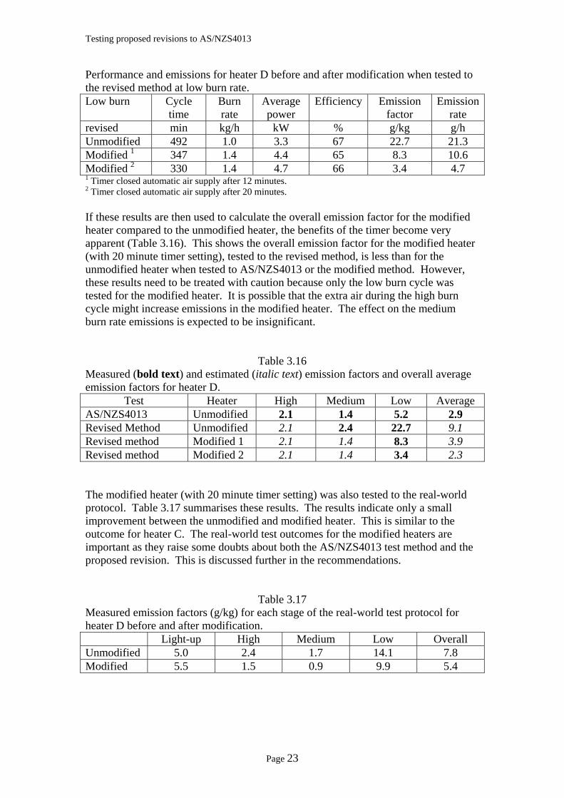
Light-up 32 5.0 21.2 5.0 4.6 High burn 124 3.8 7.8 2.4 6.7 Medium burn 205 2.7 3.8 1.7 5.3 Slow burn 973 1.1 12.6 14.1 83.4 Heater D was modified by attaching a timing device to the bottom of the firebox directly below the door hinge. A linkage from the door to the timer wound the timer up as the door opened, but closing the door did not influence the timer. A light metal rod attached to the timer closed a hinged flap covering an air inlet to the combustion-air preheating chamber. As the timer counted back to zero the arm closed the flap quite quickly over the last minute of a 10 to 20 minute timer cycle. Two different timer cycles were trialled. In the first, the timer closed the air flap roughly ten minutes after the door was closed. On slow burn, combustion was still poor (i.e. considerable smoke) so testing was repeated with a longer timer interval of about 20 minutes. This led to improved performance. The modification led to substantial reductions in emissions when tested to the proposed revised method (Table 3.15). By supplying additional combustion air for twelve minutes the emission factor was cut by 63% (Modified-1) and by supplying the additional combustion air for about 20 minutes the emission factor was cut by 85% (Modified-2). The efficiency was not significantly changed.
Table 3.15
Page 22
Testing proposed revisions to AS/NZS4013
Performance and emissions for heater D before and after modification when tested to the revised method at low burn rate. Low burn Cycle
time Burn rate
Average power
Efficiency Emission factor
Emission rate
revised min kg/h kW % g/kg g/h Unmodified 492 1.0 3.3 67 22.7 21.3 Modified 1 347 1.4 4.4 65 8.3 10.6 Modified 2 330 1.4 4.7 66 3.4 4.7 1 Timer closed automatic air supply after 12 minutes. 2 Timer closed automatic air supply after 20 minutes. If these results are then used to calculate the overall emission factor for the modified heater compared to the unmodified heater, the benefits of the timer become very apparent (Table 3.16). This shows the overall emission factor for the modified heater (with 20 minute timer setting), tested to the revised method, is less than for the unmodified heater when tested to AS/NZS4013 or the modified method. However, these results need to be treated with caution because only the low burn cycle was tested for the modified heater. It is possible that the extra air during the high burn cycle might increase emissions in the modified heater. The effect on the medium burn rate emissions is expected to be insignificant.
Table 3.16 Measured (bold text) and estimated (italic text) emission factors and overall average emission factors for heater D.
Test Heater High Medium Low Average AS/NZS4013 Unmodified 2.1 1.4 5.2 2.9 Revised Method Unmodified 2.1 2.4 22.7 9.1 Revised method Modified 1 2.1 1.4 8.3 3.9 Revised method Modified 2 2.1 1.4 3.4 2.3 The modified heater (with 20 minute timer setting) was also tested to the real-world protocol. Table 3.17 summarises these results. The results indicate only a small improvement between the unmodified and modified heater. This is similar to the outcome for heater C. The real-world test outcomes for the modified heaters are important as they raise some doubts about both the AS/NZS4013 test method and the proposed revision. This is discussed further in the recommendations.
Table 3.17 Measured emission factors (g/kg) for each stage of the real-world test protocol for heater D before and after modification. Light-up High Medium Low Overall Unmodified 5.0 2.4 1.7 14.1 7.8 Modified 5.5 1.5 0.9 9.9 5.4
Page 23
Testing proposed revisions to AS/NZS4013
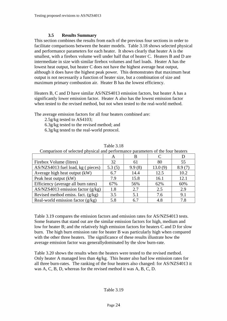
3.5 Results Summary This section combines the results from each of the previous four sections in order to facilitate comparisons between the heater models. Table 3.18 shows selected physical and performance parameters for each heater. It shows clearly that heater A is the smallest, with a firebox volume well under half that of heater C. Heaters B and D are intermediate in size with similar firebox volumes and fuel loads. Heater A has the lowest heat output, but heater C does not have the highest average heat output, although it does have the highest peak power. This demonstrates that maximum heat output is not necessarily a function of heater size, but a combination of size and maximum primary combustion air. Heater B has the lowest efficiency. Heaters B, C and D have similar AS/NZS4013 emission factors, but heater A has a significantly lower emission factor. Heater A also has the lowest emission factor when tested to the revised method, but not when tested to the real-world method. The average emission factors for all four heaters combined are:
2.5g/kg tested to AS4103; 6.3g/kg tested to the revised method; and 6.3g/kg tested to the real-world protocol.
Table 3.18 Comparison of selected physical and performance parameters of the four heaters
A B C D Firebox Volume (litres) 32 61 80 55 AS/NZS4013 fuel load, kg ( pieces) 5.3 (5) 9.9 (8) 13.0 (9) 8.9 (7) Average high heat output (kW) 6.7 14.4 12.5 10.2 Peak heat output (kW) 7.9 15.8 16.1 12.1 Efficiency (average all burn rates) 67% 56% 62% 60% AS/NZS4013 emission factor (g/kg) 1.8 2.7 2.5 2.9 Revised method emiss. fact. (g/kg) 3.5 5.1 7.6 9.1 Real-world emission factor (g/kg) 5.8 6.7 4.8 7.8 Table 3.19 compares the emission factors and emission rates for AS/NZS4013 tests. Some features that stand out are the similar emission factors for high, medium and low for heater B; and the relatively high emission factors for heaters C and D for slow burn. The high burn emission rate for heater B was particularly high when compared with the other three heaters. The significance of these results illustrate how the average emission factor was generallydominated by the slow burn-rate. Table 3.20 shows the results when the heaters were tested to the revised method. Only heater A managed less than 4g/kg. This heater also had low emission rates for all three burn-rates. The ranking of the four heaters also changed: for AS/NZS4013 it was A, C, B, D, whereas for the revised method it was A, B, C, D.
Table 3.19
Page 24
Testing proposed revisions to AS/NZS4013
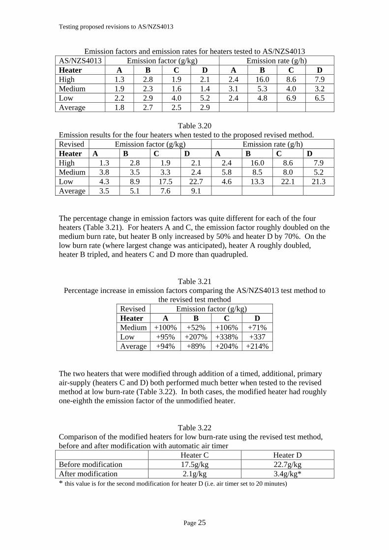
Emission factors and emission rates for heaters tested to AS/NZS4013 AS/NZS4013 Emission factor (g/kg) Emission rate (g/h) Heater A B C D A B C D High 1.3 2.8 1.9 2.1 2.4 16.0 8.6 7.9 Medium 1.9 2.3 1.6 1.4 3.1 5.3 4.0 3.2 Low 2.2 2.9 4.0 5.2 2.4 4.8 6.9 6.5 Average 1.8 2.7 2.5 2.9
Table 3.20 Emission results for the four heaters when tested to the proposed revised method. Revised Emission factor (g/kg) Emission rate (g/h) Heater A B C D A B C D High 1.3 2.8 1.9 2.1 2.4 16.0 8.6 7.9 Medium 3.8 3.5 3.3 2.4 5.8 8.5 8.0 5.2 Low 4.3 8.9 17.5 22.7 4.6 13.3 22.1 21.3 Average 3.5 5.1 7.6 9.1 The percentage change in emission factors was quite different for each of the four heaters (Table 3.21). For heaters A and C, the emission factor roughly doubled on the medium burn rate, but heater B only increased by 50% and heater D by 70%. On the low burn rate (where largest change was anticipated), heater A roughly doubled, heater B tripled, and heaters C and D more than quadrupled.
Table 3.21 Percentage increase in emission factors comparing the AS/NZS4013 test method to
the revised test method Revised Emission factor (g/kg) Heater A B C D Medium +100% +52% +106% +71% Low +95% +207% +338% +337 Average +94% +89% +204% +214%
The two heaters that were modified through addition of a timed, additional, primary air-supply (heaters C and D) both performed much better when tested to the revised method at low burn-rate (Table 3.22). In both cases, the modified heater had roughly one-eighth the emission factor of the unmodified heater.
Table 3.22 Comparison of the modified heaters for low burn-rate using the revised test method, before and after modification with automatic air timer Heater C Heater D Before modification 17.5g/kg 22.7g/kg After modification 2.1g/kg 3.4g/kg* * this value is for the second modification for heater D (i.e. air timer set to 20 minutes)
Page 25
Testing proposed revisions to AS/NZS4013
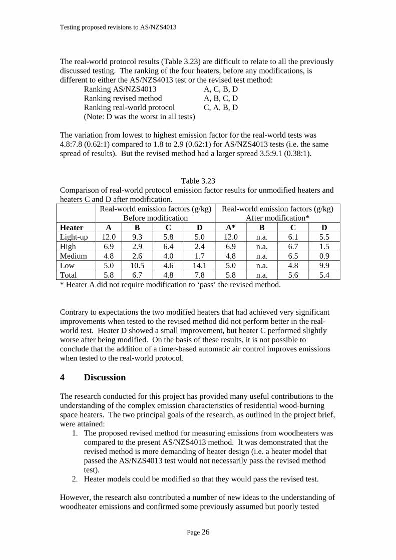
The real-world protocol results (Table 3.23) are difficult to relate to all the previously discussed testing. The ranking of the four heaters, before any modifications, is different to either the AS/NZS4013 test or the revised test method:
Ranking AS/NZS4013 A, C, B, D Ranking revised method A, B, C, D Ranking real-world protocol C, A, B, D (Note: D was the worst in all tests)
The variation from lowest to highest emission factor for the real-world tests was 4.8:7.8 (0.62:1) compared to 1.8 to 2.9 (0.62:1) for AS/NZS4013 tests (i.e. the same spread of results). But the revised method had a larger spread 3.5:9.1 (0.38:1).
Table 3.23 Comparison of real-world protocol emission factor results for unmodified heaters and heaters C and D after modification. Real-world emission factors (g/kg)
Before modification Real-world emission factors (g/kg)
After modification* Heater A B C D A* B C D Light-up 12.0 9.3 5.8 5.0 12.0 n.a. 6.1 5.5 High 6.9 2.9 6.4 2.4 6.9 n.a. 6.7 1.5 Medium 4.8 2.6 4.0 1.7 4.8 n.a. 6.5 0.9 Low 5.0 10.5 4.6 14.1 5.0 n.a. 4.8 9.9 Total 5.8 6.7 4.8 7.8 5.8 n.a. 5.6 5.4 * Heater A did not require modification to ‘pass’ the revised method. Contrary to expectations the two modified heaters that had achieved very significant improvements when tested to the revised method did not perform better in the real-world test. Heater D showed a small improvement, but heater C performed slightly worse after being modified. On the basis of these results, it is not possible to conclude that the addition of a timer-based automatic air control improves emissions when tested to the real-world protocol. 4 Discussion The research conducted for this project has provided many useful contributions to the understanding of the complex emission characteristics of residential wood-burning space heaters. The two principal goals of the research, as outlined in the project brief, were attained:
1. The proposed revised method for measuring emissions from woodheaters was compared to the present AS/NZS4013 method. It was demonstrated that the revised method is more demanding of heater design (i.e. a heater model that passed the AS/NZS4013 test would not necessarily pass the revised method test).
2. Heater models could be modified so that they would pass the revised test. However, the research also contributed a number of new ideas to the understanding of woodheater emissions and confirmed some previously assumed but poorly tested
Page 26
Testing proposed revisions to AS/NZS4013
aspects of heater operation influencing emissions. This discussion deals with the main outcomes of the research under a series of specific headings. 4.1 Comparison of AS/NZS4013 and the Revised Method The emission tests showed clearly that emissions are higher when air control is set to medium or low immediately after refuelling a woodheater. All four appliances, for both medium and low burn-rates, had higher emission factors when tested to the revised method than the AS/NZS4013 method. The overall average increase in emission factors between the two methods was a factor of 2.5. It could be argued that this indicates that the revised test method, with an emission limit of 4g/kg, is similar to the AS/NZS4013 method with an emission limit of 1.6g/kg (i.e. 4 ÷ 2.5). This relationship, however, may not be consistent, because the rankings of the four heaters tested changed slightly when tested to the revised method compared to the AS/NZS4013 method, thus indicating that simply dividing the 4g/kg limit by 2.5 will not apply to all heater models. The observation that closing the air control soon after reloading fuel is closer to actual use patterns in the home suggests that the revised method might be more realistic than using the AS/NZS4013 method with a lower emission limit. However, it must be stressed that only limited survey information is currently available about how people actually use their heaters in their homes. 4.2 Heater Modification Results from the addition of timers to two of the heater models demonstrate that modifications can make it possible for some heaters to meet the 4g/kg limit applied to the revised method. As discussed in section 2.5, several other options would also be available to manufacturers. This research only tested a very basic mechanical timing device. Although the modifications made to the two heaters were trial constructions unsuitable for general consumer use, it is understood that robust, cheap, commercial timers are available. Some heater models lend themselves to straightforward addition of such timers, especially heaters with primary combustion air entering from the bottom of the firebox (as heater D had). The advantage of bottom entry primary air is that it allows the timer to be positioned in the plinth with minimum linkages to air controls. Heater designs with air entering above the door (a very common design feature) would require either a more complex linkage (so the timer is still in the plinth), a supplementary air supply that does not mix with the normal primary air supply (e.g. entering at the back of the firebox or below the door), or ducts to bring the primary air supply from the bottom of the firebox. The very preliminary trials with automatic air controls carried out as part of this research suggest that gradually closing off the supplementary air supply helps to maintain good flame in the combustion chamber when moving to the low air setting. This could be a significant advantage. In the AS/NZS4013 test the combustion air supply is instantly changed from high to low instantly. This sudden change in combustion air supply often causes the flame to go out, leading to higher emissions.
Page 27
Testing proposed revisions to AS/NZS4013
One possible disadvantage of using supplementary combustion air is that it could provide too much air for normal high burn-rate conditions, which could increase emissions. No tests were carried out to test this hypothesis during this research due to time constraints. However, if an oversupply of air in this way does present a problem it could easily be resolved by overriding the supplementary air supply when the manual air control is set to high. Given that the automatic controls developed for these tests had to be installed and trialled in just one day (before moving to the formal testing which took several days) and only basic metal working tools were available, it was encouraging that significant emission reductions were achieved. The two heaters that were modified achieved lower emission factors for the revised test method than their emission factors (unmodified) for the AS/NZS4013 test (see Tables 3.7 and 3.12). 4.3 Importance of Good Combustion before Slow Burn The difference between the AS/NZS4013 emission factors and the revised method emission factors validates the advice given to householders over the past 20 years stressing the importance of leaving the air control fully open for 15 to 20 minutes after refuelling. It is just unfortunate so few woodheater users seem to have heeded this advice. As illustrated by these results, the simple procedure of running the heater on high for 15 to 20 minutes leads to an overall reduction of emissions by about a factor of 2.5. Considering low burn-rates alone, the reduction in emissions averages out to a factor of 3.7 (Tables 3.19 and 3.20). In other words, households using heaters overnight on slow burn emit 3.7 times more particles if they do not run the heater on high for 15 to 20 minutes before turning to low. 4.4 Real-World Emission Test Protocol The real-world test protocol provides an opportunity for a quite different set of standard tests. It shows that generally repeatable results might be obtained through a test regime quite close to anticipated household use. A single sequence of emission tests takes one full day, so it would be practical to do a set of three or four repeat sets of tests in the same time as the current AS/NZS4013 test (i.e. about one week). The method would need to be refined before it could be seriously proposed as an alternative to AS/NZS4013 because some critical steps in the process are not yet well enough defined. The problems of providing efficiency and power measurements would also have to be overcome. This might involve some slightly more sophisticated calibration of the calorimeter rooms used for testing to allow for thermal mass of the room. Thorough surveys should also be carried out to gain a better picture of typical woodheater use. 4.5 Do AS/NZS4013 and the Revised Method Give Realistic Emission
Measurements? The observation that the two modified heaters did not perform significantly better in the real-world tests, despite performing much better in the revised test method, raises some awkward questions about how realistic the standard tests are. Unfortunately,
Page 28
Testing proposed revisions to AS/NZS4013
there was only time to conduct one real-world test on each of the two modified heaters. The possibility that random variations in the real-world tests led to the unexpected outcome cannot be ruled out. The real-world test protocol differed from the revised standard method in three important ways.
1. It included the light-up phase, which is not included in the standard test. However, in terms of total emissions the light-up phase only contributed a small proportion of total emissions and cannot account for the failure of the modified heaters to perform better in the real-world test.
2. It uses larger pieces of firewood and, for the low burn cycle, 50% more mass of firewood. Could the larger log sizes play such a significant role in determining the total emissions despite better ignition of the load for low and medium burn rates? It is not possible to answer this question based on the analysis of results carried out to date.
3. The real-world test adds the first full fuel load to a very modest coal bed (at the end of the light-up phase). Many of the real-world test cycles showed unusually high emissions for this high burn-rate period. Perhaps this is an issue?
Studies in the United States have shown that there is no correlation between laboratory measured emission factors and real-world emission factors (as measured in people’s homes) for clean burning heaters. Similar results have been obtained in New Zealand (recent research, as yet unpublished). This suggests something is happening in people’s homes that is masking the clean-burn features recorded during laboratory tests. It must be stressed that the real-world protocol used in this research has not undergone sufficient testing to understand all of the parameters that might influence emission factors. Nor has it been demonstrated that it is an adequate reflection of the way people really do use their heater in their homes. One of the important issues to be addressed in any heater emission testing standard method is whether or not the rankings (i.e. cleanest to dirtiest) are reflected in heater use in people’s homes. There is some evidence from the United States that the emission rates determined in standard tests bear little relationship to emission rates for heater used in people’s homes. Figure 4.1 illustrates this point. The important thing to note is that there seems to be no correlation between laboratory and household measured emissions. As indicated in Section 3 (above), the rankings of the four heaters used in this research changed depending on how the emissions were measured. This aspect of the Australian and New Zealand woodheater emissions test method requires further investigation.
Page 29
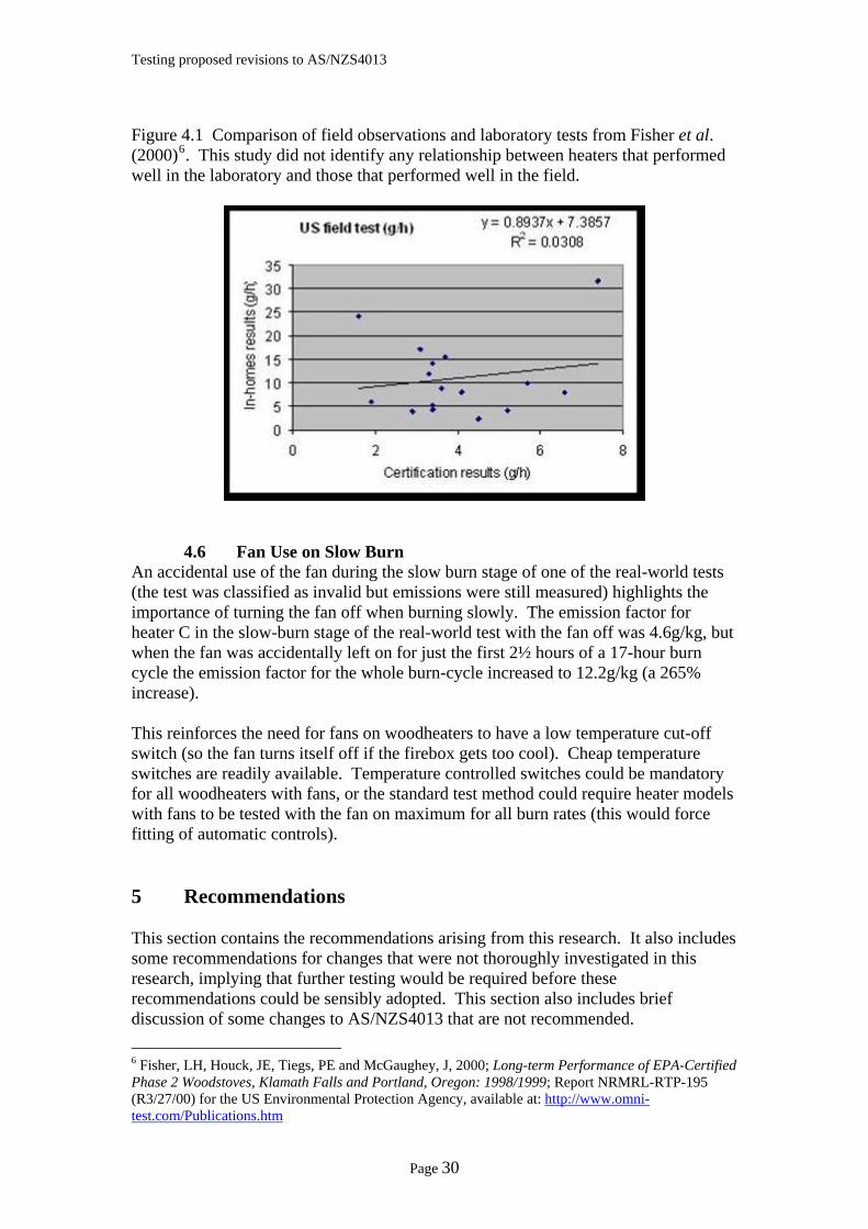
Testing proposed revisions to AS/NZS4013
Figure 4.1 Comparison of field observations and laboratory tests from Fisher et al. (2000)6. This study did not identify any relationship between heaters that performed well in the laboratory and those that performed well in the field.
4.6 Fan Use on Slow Burn An accidental use of the fan during the slow burn stage of one of the real-world tests (the test was classified as invalid but emissions were still measured) highlights the importance of turning the fan off when burning slowly. The emission factor for heater C in the slow-burn stage of the real-world test with the fan off was 4.6g/kg, but when the fan was accidentally left on for just the first 2½ hours of a 17-hour burn cycle the emission factor for the whole burn-cycle increased to 12.2g/kg (a 265% increase). This reinforces the need for fans on woodheaters to have a low temperature cut-off switch (so the fan turns itself off if the firebox gets too cool). Cheap temperature switches are readily available. Temperature controlled switches could be mandatory for all woodheaters with fans, or the standard test method could require heater models with fans to be tested with the fan on maximum for all burn rates (this would force fitting of automatic controls). 5 Recommendations This section contains the recommendations arising from this research. It also includes some recommendations for changes that were not thoroughly investigated in this research, implying that further testing would be required before these recommendations could be sensibly adopted. This section also includes brief discussion of some changes to AS/NZS4013 that are not recommended. 6 Fisher, LH, Houck, JE, Tiegs, PE and McGaughey, J, 2000; Long-term Performance of EPA-Certified Phase 2 Woodstoves, Klamath Falls and Portland, Oregon: 1998/1999; Report NRMRL-RTP-195 (R3/27/00) for the US Environmental Protection Agency, available at: http://www.omni-test.com/Publications.htm
Page 30
Testing proposed revisions to AS/NZS4013
The proposed revision to the standard addresses one of the important differences between the way heater emissions are tested in the laboratory (AS/NZS4013) and the way heaters are used in the home, i.e. the common practice of reducing the primary air supply immediately after adding a load of fuel. However, the revised test method does not pick up several other important, or possibly important, aspects of common misuse of woodheaters in people’s homes. This revision of the standard is a good opportunity to make additional changes to the method so that manufacturers are not faced with the prospect of rapidly ‘moving goal-posts’. The disadvantages of taking a more holistic look at shortcomings in the present test method are that it would delay the adoption of revisions, and it would require a commitment of additional research funding from somewhere. The significance of delays in finalising any changes to the standard should not be underestimated. The fact that a change in the standard has been flagged means that manufactures with new heater models are likely to delay any testing to the existing standard to avoid the need for retesting within a short time. Thus development of new products is likely to be held up. It should also be noted that no significant changes to the emission test method itself have been made since the original method was published in 1992, although the emission limit was changed from 5.5g/kg to 4g/kg in 1999. In 1999, many heater models tested already met the 4g/kg limit (about 71% of tested heaters), and those that did not, generally, only required minor changes (an increase in minimum air) to comply.
(a) Revised test method. The proposed revision to the present test method does seem a sensible and timely change to the standard. On the basis of four heater models tested, the revised method gave emission factors about 2.5 times greater than AS/NZS4013. It might be argued that a similar outcome could be achieved by reducing the limit in the present method by the same ratio, i.e. from 4 to 1.6g/kg (or 1.5g/kg as discussed at the last standards committee meeting). However, the revised method has the advantage of adopting an operating procedure that seems to be closer to operation in people’s homes than the present test method. On the other hand, the present method represents ‘correct’ heater operation. Many years of community education does not seem to have swayed the majority of woodheater owners to correct use, so perhaps the time has come to change the method. It should be noted that an effective reduction in the maximum allowed emission factor by a factor of 2.5 is a significant imposition on the woodheater manufacturing industry. It will require significant testing and modification of many of the heaters now on the market.
(b) Heater fan controls. The revision to the standard should include stricter controls on the use of heat circulating fans on appliances. This research, and earlier studies in 2003, showed that use of a fan when the heater is operated at its slow burn rate leads to large increases in emissions. It is recommended that a revision to the standard should be considered requiring a fan, if fitted, to be run on the maximum fan setting for all tests, and that automatic fan controls, if fitted, should be operating normally. This would ensure that either: (a) heaters were designed to burn cleanly with the fan
Page 31
Testing proposed revisions to AS/NZS4013
operating for all burn rates; or (b) a temperature sensor was fitted to turn the fan off if the firebox cooled below a pre-set temperature.
(c) Large logs for slow burn. The real-world protocol tests carried out in this research demonstrated some differences between heater models that appeared to be influenced by the change to larger logs and, for slow burn rates, larger fuel loads. For this reason, it is recommended that consideration be given to inclusion of an extra test to the standard high/medium/low burn rate cycles. A single slow burn cycle, using larger logs and a larger fuel load, should be carried out following the third of the medium burn-rate standard tests. The emission factor from this test should not be included when quoting the average emission factor, rather there should be a requirement that this test achieve an emission factor less than double the pass/fail limit for the average of the nine high/medium/low burn cycles (i.e. if the emission factor limit remains at 4g/kg, the limit for this extra test cycle should be 8g/kg). This would achieve two things: (a) it would eliminate heater designs that performed badly when operated with larger logs; and (b) it would provide manufacturers with a realistic measure of extended burn time (i.e. a standard method for determining how many hours a heater could operate on a single load of fuel while maintaining a relatively clean burn). The reason for recommending that this test be carried out at the end of the third medium burn cycle is to minimise any extra testing costs. It is also considered more appropriate to do the tests after a medium cycle because this is likely to be similar to what happens in people’s homes (i.e. the heater has been running at high or medium in the evening and it is then loaded up and set to slow burn so it is still running in the morning).
(d) Light-up. It would be possible to include a light-up test (i.e. measurement of emissions during the lighting of a cold heater) as part of a revised standard method, although it seems less useful than the low burn, large log test. The reasons why it might be less useful are that emissions during the lighting of a heater are extremely dependant on the method used, and operators have widely differing approachs. So, even though a reasonable degree of consistency was obtained during the testing of these four heater models by using a well defined lighting procedure, it is anticipated that quite different emission factors would have been obtained if a different procedure was used. This hypothesis was not tested in this research, but if a light-up test is to be included in the standard, research would be required to determine the effect of the various lighting methods. While the emissions rates during light up are high, they only continue for a short length of time and so contribute a relatively small proportion of total emissions. For these reasons, it is not recommended that the light-up stage of woodheater operation be included in the standard test.
Page 32
Testing proposed revisions to AS/NZS4013
(e) Real-world protocol. It is possible to include one or more real-world test sequences (i.e. the light-up, high burn, medium burn and low burn) in the standard. If a requirement for, say, two real-world test sequences was added to the standard it would add two to three days to the overall test time, increasing test costs by about 40%. It is not demonstrated that this would contribute to the overall rigor of the test (i.e. it is felt that a single low burn with larger logs as recommended above should be sufficient). It is also be possible to replace the existing standard test method with a number of repeat sequences of the real-world test. If the average of three test sequences were used, the test time would be roughly the same as the present test (i.e. about 5 days). However, the real-world test sequence cannot be used for determining efficiency unless significant changes to the calorimeter room design and its calibration to take account of thermal mass were made. Also, the real-world approach provides much less opportunity for addressing heater design flaws as is now done using the three discrete burn rates. Thus, while the real-world test approach offers excellent research and development opportunities, it is not recommended as a major part of any standard emission test for certification purposes.
(f) Log loading geometry. One aspect of household use of woodheaters that is thought to contribute to increased emissions has not been investigated in this research. That is the practice of loading the logs parallel to the door of the heater. This occurs when heater designs are considerably wider than they are deep. Provided the heater operating instructions state that logs should be loaded so they are perpendicular to the door (as most instructions do), the testing is carried out with this loading geometry. However, some heaters are considerably wider than they are deep and it is very unlikely that householders will purchase very short logs just to comply with the instructions. If logs are loaded perpendicular to the primary airflow, they block the air entering the base of the fire and lead to high smoke emissions. This increase in emissions has not yet been measured in laboratory tests. It is possible that it is very significant. If tests confirm this, then heaters with one firebox dimension much longer than the other (e.g. with width double the depth) should always be tested with logs placed parallel to this long dimension. Some testing of this effect is required with a view to including additional requirements in a revised standard. Some heater advertising actually states that logs greater than the firebox depth can be used implying they must be placed perpendicular to the air flow.
6 Conclusions This research has focussed on the implications of a proposed change to the way woodheaters are operated when undergoing standard emission testing. The main objective of the research was to test the assumption that a small change in heater operating requirements, namely a significant shortening of the time between adding a
Page 33
Testing proposed revisions to AS/NZS4013
new load of firewood and turning the air controls to medium or low, would lead to more stringent design requirements and lower emissions. The results of tests on four heater models strongly supported this assumption. The reduction in emissions are similar to maintaining the present test method and lowering the pass/fail limit from 4g/kg to 1.5g/kg, but the proposed revision has the advantage of more closely representing the way people use heaters in their homes. The research identified two other shortcomings in the present standard test method: the first is the failure of the present test method to adequately deal with the high emissions resulting from use of a heater-fan during a slow burn; and the second is the possibility of increased emissions if logs are placed parallel to the door rather than perpendicular (although this aspect of the test was not adequately covered in this research). If the emission standard is to undergo a significant rewriting then these two factors should be addressed in the revision. Two heaters were modified by adding automatic air control devices designed to reduce emissions during medium and low burn cycles. The devices achieved the desired emission reductions and demonstrated that door-triggered timers are possible. However, the automatic controls were flimsy and would need considerable development to make them durable enough for a commercial heater. The inclusion of a new real-world protocol, which attempts to duplicate the way heaters are used in people’s homes, identified some important aspects of the combustion process and the way emissions are affected. It is recommended that an additional test be included in the standard method aimed at including emission measurements when large logs are burnt for ‘overnight’ heater operation. This test would cut out heater designs that produced high emissions when burning large logs, but it would also provide the woodheater industry with a standard (and realistic) means of measuring the maximum burn-time for a single load of fuel. The research has also raised a number of new questions about woodheater design and operation. For example, the modified heaters did not perform significantly better when tested to the real-world protocol. Only very limited testing was possible due to time constraints, but the results were quite unexpected. A huge volume of data has been generated during this research, only some of which has been adequately analysed. Several burn cycles yielded unexpectedly high or low emissions and further analysis of flue and combustion chamber temperatures might give some clues as to why this occurred. Analysis of the results will continue beyond the formal end to the project. The combustion processes taking place in woodheaters are complex and inadequately understood. However, there appears to be considerable potential for development of heaters that will perform better when used in people’s homes as well as in the laboratory. This research has added to the information available to industry, pollution control authorities and research organisations. It is hoped that it will lead to technical innovations that will provide cleaner burning and more efficient woodheaters.
References All material cited in this report has been referenced in corresponding footnotes.
Page 34