Embed Size (px)
Citation preview
!! !! !!!!!!!!!!!!!!www.solarnet-east.eu
!!!!
SOLARNET Project
!
This project is supported by the European Commission’s FP7 Capacities Programme for the period April 2013 - March 2017 under the Grant Agreement number 312495.
!
!
!
!!!!
DELIVERABLE!D60.1!
Preliminary Report of FEA of Large FPI
WP60 Advanced Instrumentation Development
1ST Reporting Period
November 2014

!! !! !!!!!!!!!!!!!!www.solarnet-east.eu
!!!!
SOLARNET Project
!
This project is supported by the European Commission’s FP7 Capacities Programme for the period April 2013 - March 2017 under the Grant Agreement number 312495.
!
PROJECT!GENERAL!INFORMATION!
!
Grant!Agreement!number:!312495!
Project!acronym:!SOLARNET!
Project!title:!HighKResolution!Solar!Physics!Network!
Funded! under:! FP7KINFRASTRUCTURES:! INFRAK2012K1.1.26! K! Research!
Infrastructures!for!HighKResolution!Solar!Physics!
Funding!scheme:!Combination!of!Collaborative!Project!and!Coordination!
and!Support!Action!for!Integrating!Activities!
From:!2013K04K01!to!2017K03K31!
Date! of! latest! version!of!Annex! I! against!which! the! assessment!will! be!
made:!13/02/2013!
Periodic!report:!1st!X!!!2nd!�!!!3rd!�!!!4th!�!!!!!!! !
Period!covered:!from!01/04/2013! to!30/09/2014!
Project's!coordinator:!Dr.!Manuel!Collados!Vera,!IAC.!
Tel:!(34)!922!60!52!00! !
Fax:!(34)!922!60!52!10!! !!!
EKmail:[email protected]!
Project!website!address:!http://solarnetKeast.eu/!
!
!

A.D.S. International SRL – www.ads-int.com
PROGRAMME: Modified ICOS ET-150 FP CUSTOMER: Università degli studi di Roma "Tor Vergata" CONTRACTOR: A.D.S. International s.r.l. via Roma, 87 23868 Valmadrera (LC) - ITALY Tel.: +39-0341201950 Fax: +39-0341201950 – int 8 DOCUMENT TITLE: Alternative ICOS ET150 (E3) Finite Elements verification Issue: A Date: 18/03/2014 DOCUMENT ID: 155-RP-AD-13002 DOCUMENT TYPE: REPORT P.Lazzarini 18/03/2014 PREPARED BY: ....................................................... ................................ Signature Date D. Gallieni 18/03/2014 ISSUED BY: ……................................................. …….......................... Signature Date

Modified ET150 (E3) - Finite Elements design Doc. : 155-RP-AD-13002 Issue: A Page: 2 of 34
A.D.S. International SRL – www.ads-int.com
CHANGES RECORD
Version Date Description Pages/Sections A 18/03/2014 First issue All

Modified ET150 (E3) - Finite Elements design Doc. : 155-RP-AD-13002 Issue: A Page: 3 of 34
A.D.S. International SRL – www.ads-int.com
TABLE OF CONTENTS 1 RELATED DOCUMENTS ..................................................................................................................................... 5 2 SCOPE OF WORK ................................................................................................................................................. 6 3 PERFORMANCES AND DATA REDUCTION METHODS ............................................................................. 7 4 MODAL PERFORMANCES ................................................................................................................................. 8
4.1 ALTERNATIVE ICOS ET-150 – NO GLUE ............................................................................................................ 8 4.1.1 Modal analysis .......................................................................................................................................... 10
4.2 ALTERNATIVE ICOS ET-150 – 0.2 MM GLUE .................................................................................................... 15 4.2.1 Modal analysis .......................................................................................................................................... 16
4.3 MODAL ANALYSIS CONCLUSIONS ........................................................................................................................ 24 5 STATIC ANALYSIS ............................................................................................................................................. 25
5.1 PRE-LOAD OF THE GLASSWORK ........................................................................................................................... 25 5.1.1 NO glue. .................................................................................................................................................... 25 5.1.2 0.2 mm glue ............................................................................................................................................... 27
5.2 VERTICAL GRAVITY ............................................................................................................................................ 28 5.2.1 NO glue ..................................................................................................................................................... 28 5.2.2 0.2 mm glue ............................................................................................................................................... 29
5.3 HORIZONTAL GRAVITY ........................................................................................................................................ 30 5.3.1 NO glue ..................................................................................................................................................... 30 5.3.2 0.2 mm glue ............................................................................................................................................... 31
5.4 EFFECTS OF ACTUATORS ELONGATIONS / MOUNTING TOLERANCES ..................................................................... 32 5.4.1 NO glue ..................................................................................................................................................... 32 5.4.2 0.2 mm glue ............................................................................................................................................... 33 5.4.3 Static analyses conclusions ....................................................................................................................... 33
6 CONCLUSIONS ................................................................................................................................................... 34
Modified ET150 (E3) - Finite Elements design Doc. : 155-RP-AD-13002 Issue: A Page: 4 of 34
A.D.S. International SRL – www.ads-int.com
LIST OF ACRONYMS E Young modulus FEM Finite Element Model / Method FEA Finite Element Analysis FPI Fabry-Perot Interferometer PTV Peak To Valley RMS Root Mean Square RSS Root Squared Sum STD Standard deviation D Coefficient Thermal Expansion U Mass density Q Poisson modulus Vyield yield stress limit

Modified ET150 (E3) - Finite Elements design Doc. : 155-RP-AD-13002 Issue: A Page: 5 of 34
A.D.S. International SRL – www.ads-int.com
1 RELATED DOCUMENTS
AD1. ET150 Mechanical details. GNL-4014-R.1. Prepared by Dr. K. Pietraszewski. AD2. Contractual letter from Università di degli Studi di Roma "Tor Vergata" - Dipartimento di Fisica, Roma 11 Luglio 2013. AD3. 69-RP-AD-06001. FE study of ICOS Fabry-Perot interferometer. ADS Int. srl. AD4. 69-RP-AD-06001. Modified ICOS Fabry-Perot interferometer. ADS Int. srl. AD5. 69-RP-AD-06001. Fabry-Perot interferometer thermoelastic analysis. ADS Int. srl. AD6. 111-RP-AD-09001. 200 mm Fabry-Perot interferometer. ADS Int. srl.

Modified ET150 (E3) - Finite Elements design Doc. : 155-RP-AD-13002 Issue: A Page: 6 of 34
A.D.S. International SRL – www.ads-int.com
2 SCOPE OF WORK
Finite Element Verification of the alternative design proposed by ICOS for the ET150 during the meeting at their premises (February 2014).
Modified ET150 (E3) - Finite Elements design Doc. : 155-RP-AD-13002 Issue: A Page: 7 of 34
A.D.S. International SRL – www.ads-int.com
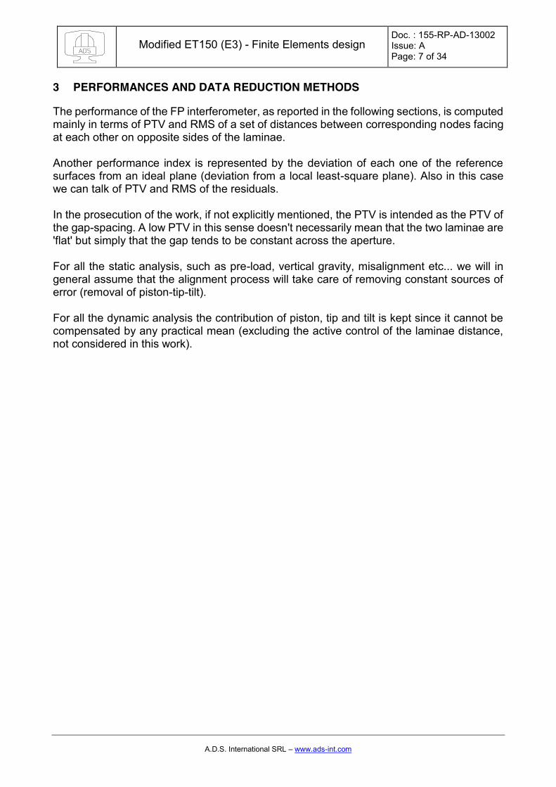
3 PERFORMANCES AND DATA REDUCTION METHODS
The performance of the FP interferometer, as reported in the following sections, is computed mainly in terms of PTV and RMS of a set of distances between corresponding nodes facing at each other on opposite sides of the laminae. Another performance index is represented by the deviation of each one of the reference surfaces from an ideal plane (deviation from a local least-square plane). Also in this case we can talk of PTV and RMS of the residuals. In the prosecution of the work, if not explicitly mentioned, the PTV is intended as the PTV of the gap-spacing. A low PTV in this sense doesn't necessarily mean that the two laminae are 'flat' but simply that the gap tends to be constant across the aperture. For all the static analysis, such as pre-load, vertical gravity, misalignment etc... we will in general assume that the alignment process will take care of removing constant sources of error (removal of piston-tip-tilt). For all the dynamic analysis the contribution of piston, tip and tilt is kept since it cannot be compensated by any practical mean (excluding the active control of the laminae distance, not considered in this work).

Modified ET150 (E3) - Finite Elements design Doc. : 155-RP-AD-13002 Issue: A Page: 8 of 34
A.D.S. International SRL – www.ads-int.com
4 MODAL PERFORMANCES
We started this study by investigating the possible dynamic issues of the ET-150 alternative design (proposed by ICOS during the meeting at their premises) in term of modal analysis and in particular as comparison with respect to the designs proposed in other phases of the project. We considered two different layouts having glue thicknesses between the three lugs and the glass plates (near zero glue thickness and 0.2 mm thickness). The behavior for the actual system, for which we don’t have a clear specification of the glue will be something in between the two solutions hereafter described. 4.1 Alternative ICOS ET-150 – NO GLUE
In the following picture, we see a FE model developed and studied by FEMAP®+NX® NASTRAN. The model is related to the active portion of the instrument (glasswork and piezo only) in order to limit the complexity of the numerical problem in view of the detailed transient analysis.
Figure 1. The FE model of the ET-150 FP alternative design by ICOS. The rubber pads (pink), the glasswork (light yellow) and the three piezo stacks (orange) are visible. The model makes use of bi-quadratic elements with parabolic shape functions.

Modified ET150 (E3) - Finite Elements design Doc. : 155-RP-AD-13002 Issue: A Page: 9 of 34
A.D.S. International SRL – www.ads-int.com
Figure 2. Alternative ICOS ET-150: close up. The rubber pads (pink), the glasswork (light yellow) and the three piezo stacks (orange) are visible. No glue is present in between the lugs and the lamina.

Modified ET150 (E3) - Finite Elements design Doc. : 155-RP-AD-13002 Issue: A Page: 10 of 34
A.D.S. International SRL – www.ads-int.com
4.1.1 Modal analysis
The most relevant modes and the related frequencies are described in the following.
Figure 3. The first resonant mode of the unit is placed at about 132 Hz and it is a lateral rigid movement of the glasswork due to the flexibility of the 3+3 rubber pads used to fix the core of the instrument to the chassis.
Figure 4. The second mode is another rigid translation (132 Hz) orthogonal to the first one.

Modified ET150 (E3) - Finite Elements design Doc. : 155-RP-AD-13002 Issue: A Page: 11 of 34
A.D.S. International SRL – www.ads-int.com
Figure 5. The third mode is a rigid twisting of the glasswork (178 Hz) again related to the flexibility of the rubber pads and the polar inertia of the glasswork.
Figure 6. The fourth mode is a rigid piston due to the flexibility of the rubber pads and the mass of the glasswork (327 Hz).
Modified ET150 (E3) - Finite Elements design Doc. : 155-RP-AD-13002 Issue: A Page: 12 of 34
A.D.S. International SRL – www.ads-int.com
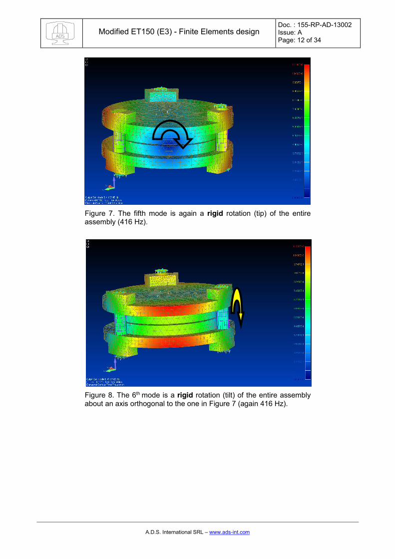
Figure 7. The fifth mode is again a rigid rotation (tip) of the entire assembly (416 Hz).
Figure 8. The 6th mode is a rigid rotation (tilt) of the entire assembly about an axis orthogonal to the one in Figure 7 (again 416 Hz).
Modified ET150 (E3) - Finite Elements design Doc. : 155-RP-AD-13002 Issue: A Page: 13 of 34
A.D.S. International SRL – www.ads-int.com
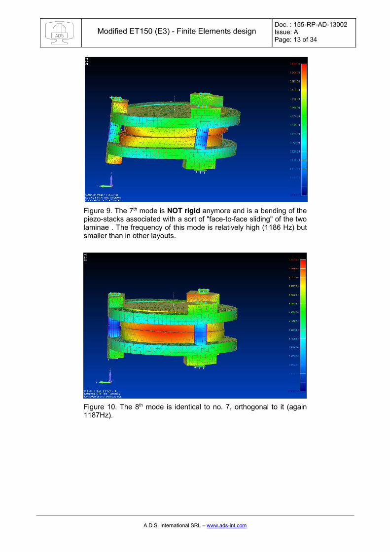
Figure 9. The 7th mode is NOT rigid anymore and is a bending of the piezo-stacks associated with a sort of "face-to-face sliding" of the two laminae . The frequency of this mode is relatively high (1186 Hz) but smaller than in other layouts.
Figure 10. The 8th mode is identical to no. 7, orthogonal to it (again 1187Hz).

Modified ET150 (E3) - Finite Elements design Doc. : 155-RP-AD-13002 Issue: A Page: 14 of 34
A.D.S. International SRL – www.ads-int.com
Figure 11. Mode 9: counter twist + piezo bending (1912 Hz).
Figure 12. Piston like mode due to flexibility of piezo stack plus own tri-foil deformation of the glass work (especially the lower block, without the central protrusion): 2131 Hz. The spacing is here affected in terms of piston movement and deformation content. This frequency is about 1KHz smaller than the original ICOS design.

Modified ET150 (E3) - Finite Elements design Doc. : 155-RP-AD-13002 Issue: A Page: 15 of 34
A.D.S. International SRL – www.ads-int.com
4.2 Alternative ICOS ET-150 – 0.2 mm GLUE
In the following picture, we see the model including a 0.2 mm thickness glue layer between the lugs and the glass’ plates.
Figure 13. Alternative ICOS ET-150: close up. The rubber pads (pink), the glasswork (light yellow) and the three piezo stacks (orange) are visible. A 0.2 mm glue layer between the lugs and the lamina is present.

Modified ET150 (E3) - Finite Elements design Doc. : 155-RP-AD-13002 Issue: A Page: 16 of 34
A.D.S. International SRL – www.ads-int.com
4.2.1 Modal analysis
Figure 14. Lateral mode at 113 Hz. Double shift on the soft elements.
Figure 15. Lateral mode at 113 Hz.
Modified ET150 (E3) - Finite Elements design Doc. : 155-RP-AD-13002 Issue: A Page: 17 of 34
A.D.S. International SRL – www.ads-int.com
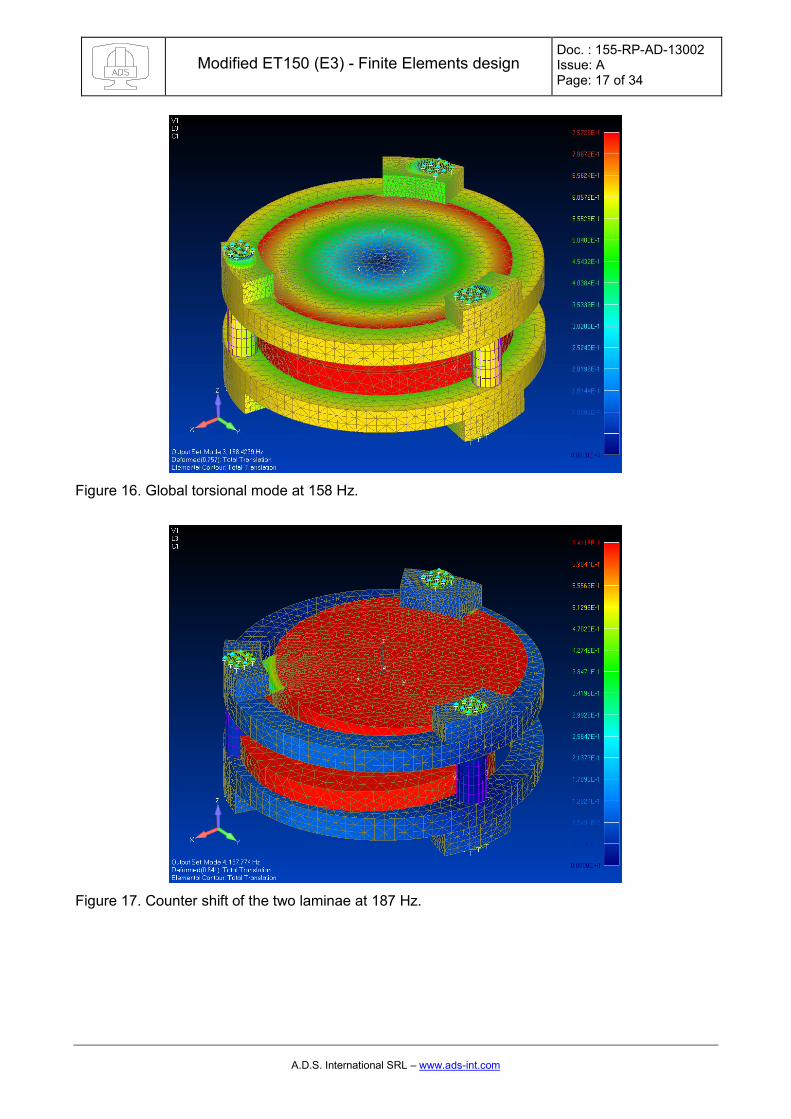
Figure 16. Global torsional mode at 158 Hz.
Figure 17. Counter shift of the two laminae at 187 Hz.

Modified ET150 (E3) - Finite Elements design Doc. : 155-RP-AD-13002 Issue: A Page: 18 of 34
A.D.S. International SRL – www.ads-int.com
Figure 18. Counter shift of the two laminae at 187 Hz.
Figure 19. Counter torsional of the two laminae at 268

Modified ET150 (E3) - Finite Elements design Doc. : 155-RP-AD-13002 Issue: A Page: 19 of 34
A.D.S. International SRL – www.ads-int.com
Figure 20. Global piston on the soft elements.
Figure 21. Global tilt of the entire assembly on the soft pads.

Modified ET150 (E3) - Finite Elements design Doc. : 155-RP-AD-13002 Issue: A Page: 20 of 34
A.D.S. International SRL – www.ads-int.com
Figure 22. Global tilt of the entire assembly on the soft pads at 401 Hz.
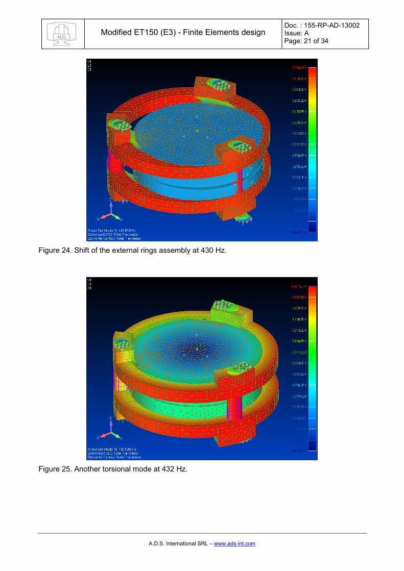
Figure 23. Shift of the external rings assembly at 430 Hz.
Modified ET150 (E3) - Finite Elements design Doc. : 155-RP-AD-13002 Issue: A Page: 21 of 34
A.D.S. International SRL – www.ads-int.com
Figure 24. Shift of the external rings assembly at 430 Hz.
Figure 25. Another torsional mode at 432 Hz.

Modified ET150 (E3) - Finite Elements design Doc. : 155-RP-AD-13002 Issue: A Page: 22 of 34
A.D.S. International SRL – www.ads-int.com
Figure 26. Piston of the laminae on the silicone glue under the lugs at 573 Hz.
Figure 27.Tilt of the laminae on the silicone glue under the lugs at 785 Hz.

Modified ET150 (E3) - Finite Elements design Doc. : 155-RP-AD-13002 Issue: A Page: 23 of 34
A.D.S. International SRL – www.ads-int.com
Figure 28. Ring bending and laminae tilt at 1000 Hz.

Modified ET150 (E3) - Finite Elements design Doc. : 155-RP-AD-13002 Issue: A Page: 24 of 34
A.D.S. International SRL – www.ads-int.com
4.3 Modal analysis conclusions
As a comment to the modal analyses results above described we can see that when the glue layer thickness (under the three lugs) tends to zero the first resonant mode directly involving the spacing way is placed at about 2131 Hz. The other rigid or quasi-rigid modes are comparable to other design. As the thickness of the glue layer increases the same mode changes and drops down in frequency because of the flexibility of the glue: for a thickness of glue of 0.2 mm (soft silicone glue), there is a piston like mode of the two laminae placed at about 573 Hz. According to the description that ICOS made of their process we believe that the thickness of the glue is limited (even though not directly controlled) and the behavior should be closed to the stiffer one. If we consider other designs we evaluated we see that the same piston mode is placed at:
x 3143 Hz for the very original ICOS design for the ET-150 x 2545 Hz for the so called “membrane design” proposed by ADS x 3520 Hz for the designed proposed by ADS with the machined holes for the piezo
In this sense, it is clear that the new alternative ICOS design will tend to be more prone to vibration in the axial direction, but likely stiff enough in normal operative conditions. A more accurate definition of the contact between the lugs and the plates would be necessary to be more accurate and better define the actual situation.
(

Modified ET150 (E3) - Finite Elements design Doc. : 155-RP-AD-13002 Issue: A Page: 25 of 34
A.D.S. International SRL – www.ads-int.com
5 STATIC ANALYSIS
In this chapter, we reported the full set of static analysis performed on the two layouts (different glue thickness) 5.1 Pre-load of the glasswork
As it has been done in the previous works, we supposed to apply a 1 MPa pre-load on each pad, as suggested by ICOS in its original design. Such a pre-load corresponds to about 0.1 mm squashing of the rubber pads which is a reasonable number in view of the mechanical installation. The total force exerted by the enclosure on each pad is about 240 N. 5.1.1 NO glue.
Figure 29. The 0.1 mm squashing applied to the rubber pads.
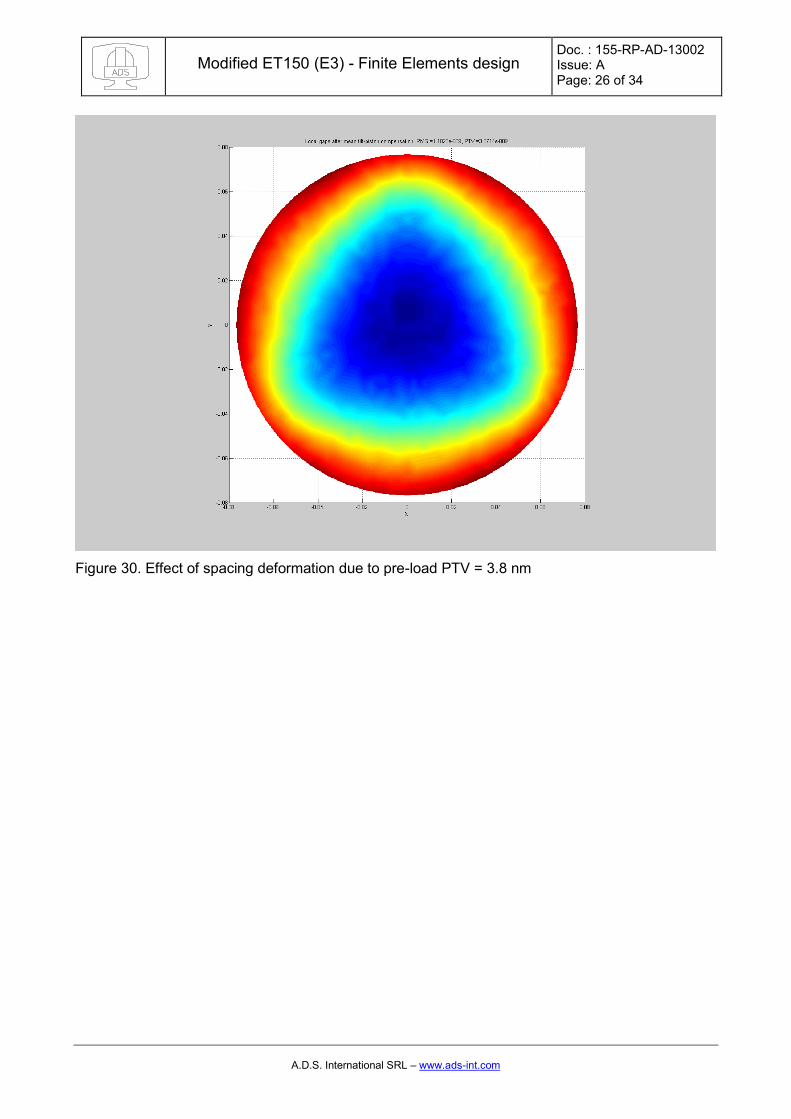
When no glue is present the coupling is pretty “hard” and a relevant amount of the deformation is transmitted to the plates.
Modified ET150 (E3) - Finite Elements design Doc. : 155-RP-AD-13002 Issue: A Page: 26 of 34
A.D.S. International SRL – www.ads-int.com
Figure 30. Effect of spacing deformation due to pre-load PTV = 3.8 nm
Modified ET150 (E3) - Finite Elements design Doc. : 155-RP-AD-13002 Issue: A Page: 27 of 34
A.D.S. International SRL – www.ads-int.com
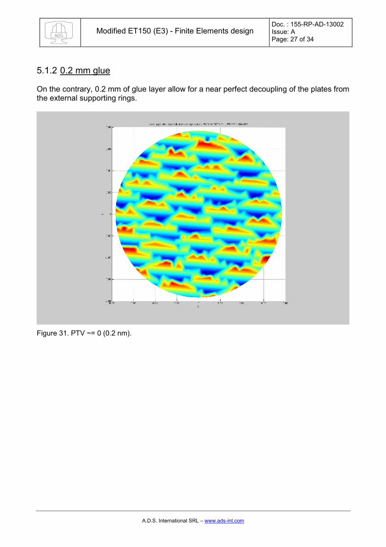
5.1.2 0.2 mm glue
On the contrary, 0.2 mm of glue layer allow for a near perfect decoupling of the plates from the external supporting rings.
Figure 31. PTV ~= 0 (0.2 nm).

Modified ET150 (E3) - Finite Elements design Doc. : 155-RP-AD-13002 Issue: A Page: 28 of 34
A.D.S. International SRL – www.ads-int.com
5.2 Vertical gravity
5.2.1 NO glue
Figure 32. PTV of the spacing in the case of vertical gravity and no glue: 43 nm PTV

Modified ET150 (E3) - Finite Elements design Doc. : 155-RP-AD-13002 Issue: A Page: 29 of 34
A.D.S. International SRL – www.ads-int.com
5.2.2 0.2 mm glue
Figure 33. PTV of the spacing in the case of vertical gravity and 0.2 mm glue: 20 nm PTV

Modified ET150 (E3) - Finite Elements design Doc. : 155-RP-AD-13002 Issue: A Page: 30 of 34
A.D.S. International SRL – www.ads-int.com
5.3 Horizontal gravity
5.3.1 NO glue
Figure 34. PTV of the spacing in the case of horizontal gravity and no glue: 0.04 nm PTV
Modified ET150 (E3) - Finite Elements design Doc. : 155-RP-AD-13002 Issue: A Page: 31 of 34
A.D.S. International SRL – www.ads-int.com
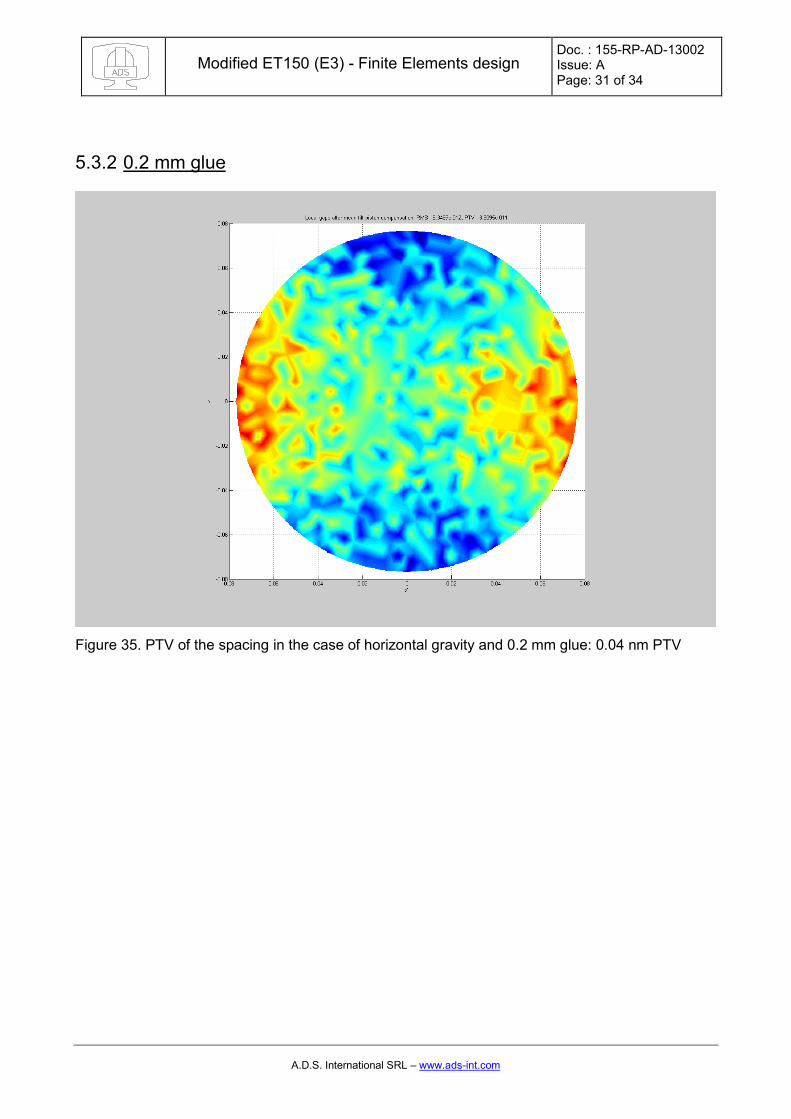
5.3.2 0.2 mm glue
Figure 35. PTV of the spacing in the case of horizontal gravity and 0.2 mm glue: 0.04 nm PTV
Modified ET150 (E3) - Finite Elements design Doc. : 155-RP-AD-13002 Issue: A Page: 32 of 34
A.D.S. International SRL – www.ads-int.com
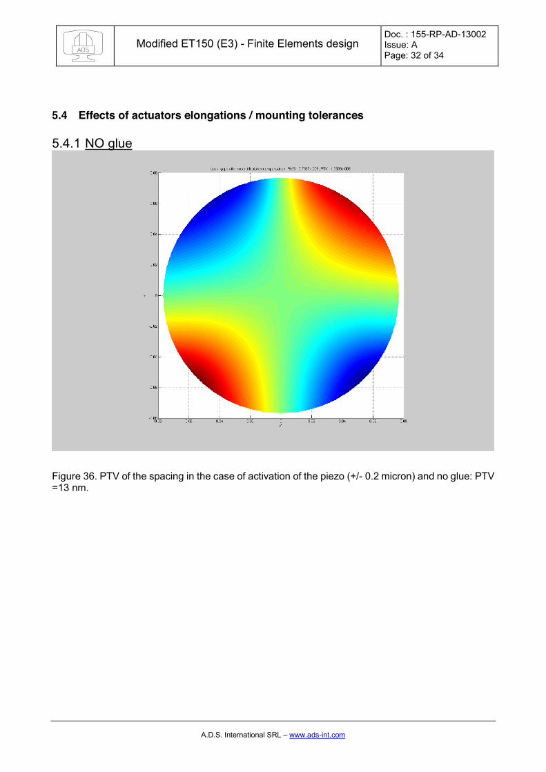
5.4 Effects of actuators elongations / mounting tolerances
5.4.1 NO glue
Figure 36. PTV of the spacing in the case of activation of the piezo (+/- 0.2 micron) and no glue: PTV =13 nm.
Modified ET150 (E3) - Finite Elements design Doc. : 155-RP-AD-13002 Issue: A Page: 33 of 34
A.D.S. International SRL – www.ads-int.com
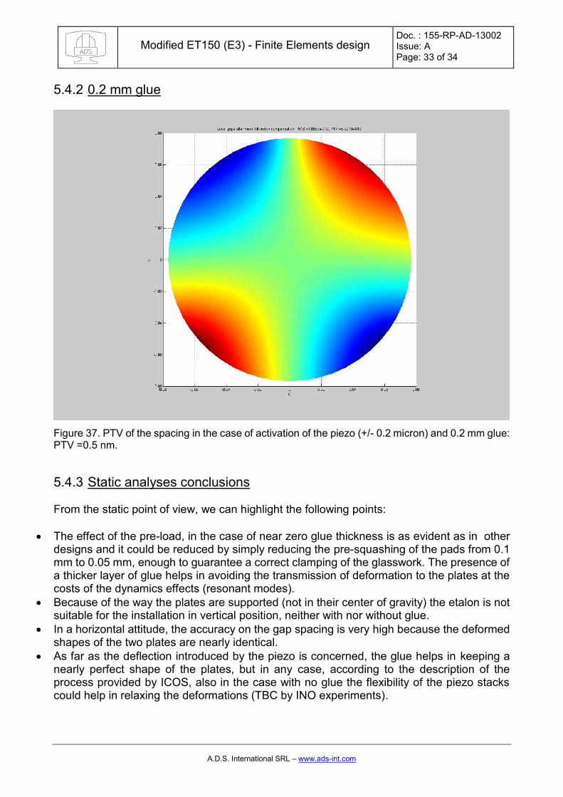
5.4.2 0.2 mm glue
Figure 37. PTV of the spacing in the case of activation of the piezo (+/- 0.2 micron) and 0.2 mm glue: PTV =0.5 nm.
5.4.3 Static analyses conclusions
From the static point of view, we can highlight the following points:
x The effect of the pre-load, in the case of near zero glue thickness is as evident as in other designs and it could be reduced by simply reducing the pre-squashing of the pads from 0.1 mm to 0.05 mm, enough to guarantee a correct clamping of the glasswork. The presence of a thicker layer of glue helps in avoiding the transmission of deformation to the plates at the costs of the dynamics effects (resonant modes).
x Because of the way the plates are supported (not in their center of gravity) the etalon is not suitable for the installation in vertical position, neither with nor without glue.
x In a horizontal attitude, the accuracy on the gap spacing is very high because the deformed shapes of the two plates are nearly identical.
x As far as the deflection introduced by the piezo is concerned, the glue helps in keeping a nearly perfect shape of the plates, but in any case, according to the description of the process provided by ICOS, also in the case with no glue the flexibility of the piezo stacks could help in relaxing the deformations (TBC by INO experiments).

Modified ET150 (E3) - Finite Elements design Doc. : 155-RP-AD-13002 Issue: A Page: 34 of 34
A.D.S. International SRL – www.ads-int.com
6 CONCLUSIONS
In conclusions, we believe that the alternative design proposed by ICOS could be interesting if used in a horizontal attitude. This because of the symmetry of the plates and the support system. This statement assumes that the initial shape of the plates after polishing & coating is guaranteed when the plates are supported in a uniform way on the entire lower surface of the glasswork. From the dynamic point of view, the results are in general less performing than other designs, in particular for the case of a thick glue layer. Besides, the placement of the capacitive sensors, likely attached to the rings and not to the plates, shall be studied very carefully in order to be representative of the actual optical surfaces also in dynamic conditions. These details are not unveiled by ICOS now. It is advisable a characterization of the gluing between the lugs and the plates in order to better understand the typical mechanical characteristics of a glued sample and finally understand how the proposed alternative solution will actually behave.