Embed Size (px)
Citation preview
American Journal of Engineering Research (AJER) 2017
American Journal of Engineering Research (AJER)
e-ISSN: 2320-0847 p-ISSN : 2320-0936
Volume-6, Issue-11, pp-155-173
www.ajer.org Research Paper Open Access
w w w . a j e r . o r g
Page 155
Proposal of a Novel Approach for Stabilization of the Image from
Omni-Directional System in the case of Human Detection &
Tracking
Dr.Vignesh Janarthanan1, Dr.Venkata Reddy Medikonda
2,
Prof.Er.Dr.G.Manoj Someswar3
1M.E., Ph.D., Professor, Sreyas Institute Of Engineering & Technology, Hyderabad, Telangana State, India.
2M.Tech., Ph.D., Associate Professor, Sreyas Institute Of Engineering & Technology, Hyderabad, Telangana
State, India. 3B.Tech., M.S.(USA), Ph.D., D.Phil., PDF, Research Professor & Scientist ‘H’, Global Research Academy –
Scientific & Industrial Research Organisation [Autonomous], Hyderabad, Telangana State, India.
Abstract: This work researches the setup and the arrangement of techniques for omni-directional framework
for human movement recognition and following. Research in the range of the omni-directional frameworks is
developing, the reason are many points of interest, for example, ease, convey ability and simple establishment.
The primary favourable position is catching a substantial bit of a space point, which is 360 degrees. Then again,
a considerable measure of issues exist and they should be understood. Pictures from omni-directional
frameworks have unexpected properties in comparison to standard point of view pictures as they have bring
down powerful determination and endure antagonistic picture contortion. In the event that the subsequent
picture is to be exhibited to a human or is additionally prepared, change and reasonable sort of adjustments must
be finished. Systems for picture change into a point of view or all encompassing perspective and geometrical
adjustments are recommended in this paper. The versatile catadioptric framework is typically inclined to
vibrations, which cause the contortion in the changed all encompassing picture. Subsequently the novel
approach for adjustment of the picture from omni-directional framework was proposed. Human face and hands
discovery assumes a critical part in applications, for example, video reconnaissance, human PC interface,
confront acknowledgment, and so on. The wide view point is essential for this sort of errands and along these
lines the omni-directional framework is reasonable for these reasons. Two distinctive following strategies are
looked at on the different sorts of video groupings caught by omni-directional framework to show the
advantages as well as downsides of the omni-directional framework and proposed techniques. The assessment
plot was produced for subjective and quantitative calculation depiction and correlation on various video sources.
Keywords: Image Processing, Computer Vision, Catadioptric System, Omni-directional Image, Mirrors,
Perspective Transformation, Panoramic Transformation, Edge Detection, Sub-pixel detection, Skin Colour,
Tracking, Human Body Parts Detection, Tracking Evaluation
----------------------------------------------------------------------------------------------------------------------------- ----------
Date of Submission: 04-11-2017 Date of acceptance: 17-11-2017
----------------------------------------------------------------------------------------------------------------------------- ----------
I. INTRODUCTION Seeing isn't a straightforward procedure: it is quite recently that vision has developed more than a huge
number of years, and there was no specific preferred standpoint in advancement giving us any sign of the
challenges of the errand. On the off chance that anything, to have done as such would have jumbled our brains
with useless data and likely impeded our response times in urgent circumstances. The people are currently
endeavouring to inspire machines to do quite a bit of their work.[1] For least complex undertakings there ought
to be no specific trouble in motorization, however for more intricate assignments the machine must be given our
prime sense, that of vision. Endeavours have been made to accomplish this, occasionally in unassuming courses,
for well more than 30 years. There is in certainty an extraordinary assortment of utilizations for fake vision
frameworks – including, obviously, all of those for which we utilize our visual faculties. The pace of securing
data has been of late expanding exponentially. That is the reason, why they happen in such regions, where
nobody assumed their use.

American Journal of Engineering Research (AJER) 2017
w w w . a j e r . o r g
Page 156
One of such classes are the meeting acknowledgment frameworks, which can be incorporated into
multi-party cooperation area. Gatherings assume a basic part in the regular daily existence of associations, work
or research gatherings. So as to hold the remarkable focuses for later reference, meeting minutes are typically
taken. Also, individuals are frequently just incidentally keen on a meeting;[2] they need to comprehend what
occurred amid it without really going to. The capacity to peruse and skim these sorts of gatherings could be very
profitable. Meeting records are expected to defeat issues, for example, poor consideration and memory. This
branch is specified with point of catching such circumstances.
The checking of the gatherings normally requires a few cameras to catch the entire scene with every
member. Regular cameras have a generally limit field of view. It could for example utilize a skillet tilt-zoom
instrument to point the camera in various ways, or it could pivot its body. As of late, an expanded enthusiasm
for omni-directional vision for applications not just in apply autonomy could be noted. In fact, omni-directional
vision, here and there likewise called all encompassing vision, can be accomplished in different ways.
Illustrations are cameras with greatly wide point focal points ("angle eye"), cameras with hyperbolically bended
mirrors mounted before a standard focal point (catadioptric imaging), sets of cameras mounted in a ring-or circle
like design, or a customary camera that pivots around a hub and takes a grouping of pictures that cover a field of
perspective of 360 degrees. Omni-directional vision gives an extensive field of view,[3] which has some
valuable properties. For example, it can encourage the following of moving items in the scene.
What are the potential applications? Video reconnaissance, automated vision, human movement observing require a wide field of view, and
are a characteristic application for omni-directional frameworks. While run of the mill reconnaissance cameras
give a thin field-of-see in a solitary heading, omni-directional innovation offers a concurrent 360° all
encompassing viewpoint of its environment. A whole room, a parking area around a building, or some other
territory can be completely seen. There are no "blind sides" between cameras, or territories of picture contortion.
In spite of the wide utilization, we plan to screen member movement at live gatherings, which are
imperative piece of ordinary human social life as was expressed previously. It is helpful to hold data created in
the gatherings for later utilize. The conventional approach of manual interpretation is tedious, present day
innovation can mechanize meeting recording and preparing. The objective is to screen member action in the
entire scene and concentrate pertinent data about development, signals, pointing, voting and other human
activities.[4]
The main necessity on any building outline is that it should work. This applies as much to vision
frameworks as to different parts of building. The chief plausibility that keeps calculations from working
appropriately is that - at any stage - critical principal factors have not been considered. For instance, a limit
following calculation can turn out badly in light of the fact that it experiences a piece of the limit that is one
pixel too wide and traverses as opposed to proceeding. Obviously, these sorts of issues emerge once in a while
(i.e., just with very particular sorts of info information). By and by, different stages in the calculation
configuration are in the extent of this work[5]. At this stage please envision that we have a scope of calculations
that all accomplish the "great" results on perfect information and that is truly a well recognized work. The
following issue is to think about them fundamentally and, specifically, to discover how they respond to genuine
information and dreadful substances, for example, clamour that go with it. These realities might be summed as
takes after:
• Noise
• Background mess
• Occlusions
• Object deformities and breakages
• Effect of stray light, shadows, and gleams
• Optical and point of view twists
• Non-uniform lightning and its results
By and large, calculations should be adequately vigorous to defeat these issues. In any case, things are
not all that basic by and by. A large portion of calculations in PC vision, not just to track human body parts, are
touchy to a few factors as specified previously. The omni-directional pictures have unexpected qualities in
comparison to pictures taken from standard cameras, which are for the most part unmistakable in the last
mentioned. Pre-processing of the omni-directional pictures tries to dispense with these viewpoints to use the
upsides of such catching framework.[6]
Why the catadioptric system?
American Journal of Engineering Research (AJER) 2017
w w w . a j e r . o r g
Page 157
A customary imaging framework is extremely constrained in its field of view, which make it
prohibitive for specific applications in computational vision. It is just equipped for securing visual data through
a moderately little strong point subtended before the picture locator. Generally, a few camcorders are utilized to
catch an expansive field of view. The greatest burdens of such methodologies are troublesome establishment,
equipment requests and higher cost. Another possibility is utilizing programming based turning cameras, which
deliver high determination all encompassing pictures. The primary drawback is that it is tedious to secure an all
encompassing picture. The utilization of these strategies is restricted to static scenes. Today, there exist an
extensive variety of vision sensors that are particularly intended to catch an all encompassing picture quickly.
Sensors comprising of different synchronized directional cameras, each of them confronting an unmistakable
heading can convey high determination omni-directional or all encompassing pictures progressively.[7] Then
again, the computational cost increments with any extra camera. It is outstanding that bended mirrors can be
utilized to build a generally constrained field of view. In what tails, we will concentrate on catadioptric sensors
joining a solitary focal point with a solitary bended mirror for checking human action due to its portability,
utilization of unfixed mounted gadgets, simple establishment, and a lower cost. This sort of observing
framework is appropriate for easygoing gatherings at better places and conditions for which the proposed
calculations will be specific. picture arrangement which is best in class in shaping a reduced picture amid a
circumstance in the omni-directional vision examine. Some picked picture preparing strategies for circle
recognition are specified. The following part examines the issue and recommends the arrangement of strategies
to limit the mutilation in the changed picture.[8] In area 4, the procedures expressed in the part 2 will be altered
to build up the reasonable arrangement of techniques for omni-directional picture adjustment into seven
sections.
What are the goals of this work? Vision algorithms have to account for the specific properties of the particular omni-directional imaging
sensor setup at hand, which contain theoretical and methodological challenges, as is the case for catadioptric
vision. Other problems such as the geometrical image distortions caused by the some kinds of mirrors require a
suitable adaptation of image interpretation methods.
The work described in this research is primarily concerned with the use of omni-directional vision
systems combining cameras with mirrors dedicated to monitor human activity during meetings. Such a system
could allow a similar comparison to standard perspective cameras yet can overcame their negative drawbacks.
As was stated above, the negative factors,[9] such as optical distortion should be minimized in order to achieve
the best results when it is used for tracking or presenting the image to a human. This implies the main goal of
this thesis is to develop suitable set of methods in order to minimize the distortion in a transformed image.
The comparison of tracking methods to different types of source data is necessary to test the results of
this work. These tests will be performed on the data set containing recordings from standard perspective
cameras and omni-directional system. The evaluation protocol and person tracking methods will be suggested
for this purpose.
What is the layout of the following chapters?
To help give the per user more viewpoint on this work, the principle content has been separated The
early parts of this work cover normal ideas of the purported catadioptric frameworks and fundamental standards
of picture arrangement which is best in class in shaping a reduced picture amid a circumstance in the omni-
directional vision examine. Some picked picture preparing strategies for circle recognition are specified.
The following part examines the issue and recommends the arrangement of strategies to limit the
mutilation in the changed picture. In area 4, the procedures expressed in the part 2 will be altered to build up the
reasonable arrangement of techniques for omni-directional picture adjustment.[10] We then proceed onward to
exploratory tests portrayal and results, which plans to exhibit the advantages and disadvantages of proposed
techniques. In area 6, two sorts of following calculations are examined. These calculations are utilized for
testing of established point of view camera groupings so the all encompassing arrangements utilized the omni-
directional framework. The assessment procedure was intended to equitably look at the following techniques on
different video sources. The last area of this work abridges the accomplished outcomes and quickly talks about
future work.
Omni-directional framework and picture handling
This section manages the best in class of the picture securing by all encompassing sensors and picture
preparing strategies which are applicable to this work. The substance of this part isn't synopsis of this theme on
the planet, yet it focuses just subjects with coordinate association with this work.
American Journal of Engineering Research (AJER) 2017
w w w . a j e r . o r g
Page 158
Image portrayal and procurement
An advanced picture is a two-dimensional (2D) discrete flag. Scientifically, such flags can be spoken to
as elements of two autonomous factors - for instance, a splendour capacity of two spatial factors.[11] A
monochrome computerized picture f (x, y) is a 2D exhibit of luminance esteems. Every component of the
exhibit is known as a pel (picture component), or all the more generally a pixel. A shading advanced picture is
regularly spoken to by a triplet of qualities, one for each of the shading channels, as in the as often as possible
utilized RGB shading plan. The individual shading esteems are generally 8-bit esteems, bringing about a sum of
3 bytes (or 24 bits) per pixel. This yields a triple increment in the capacity necessities for shading versus
monochrome pictures. Normally, there are various option strategies for putting away the picture information.
Most generally utilized are the supposed pixel-interleaved (or fit) and shading interleaved (or planar) groups.
Line insightful or segment savvy interleaving strategies are less regular.[12] In a pixel-interleaved organize,
each picture pixel is spoken to by a rundown of three esteems.
The imaging sensors assume essential part in the picture securing. The structure and operation of the
eye is fundamentally the same as an electronic camera, which is frequently used to secure true pictures. Both
depend on two noteworthy segments: a focal point get together, and an imaging sensor. The focal point get
together catches a segment of the light radiating from a question, and centres it onto the imaging sensor. The
imaging sensor at that point changes the example of light into a video flag, either electronic or neural. The term
centre means there is a coordinated match of each point on the protest with a comparing point on the screen. For
instance, consider a 1mm area on the protest. In brilliant light, there are around 100 trillion photons of light
striking this one square milli -meter range each second. Contingent upon the qualities of the surface, in the
vicinity of 1 and 99 percent of these occurrence light photons will be reflected in irregular ways. Just a little
segment of these reflected photons will go through the viewpoint. For instance, just around one-millionth of the
reflected light will go through a one centimetre distance across focal point found 3meters from the question.
Refraction in the focal point alters the course of the individual photons, contingent upon the area and edge they
strike the glass/air interface. These bearing changes cause light extending from a solitary point to come back to a
solitary point on the projection screen.[13] The greater part of the photons that reflect from the question and go
through the viewpoint are united back at the "protest" in the anticipated picture. So also, a part of the light
originating from any point on the question will go through the perspective, and be engaged to a comparing point
in the anticipated picture.
The most well-known picture sensor utilized as a part of electronic cameras is the charge coupled
gadget (CCD).[14] The CCD is an incorporated circuit that supplanted most vacuum tube cameras in the 1980s,
similarly as transistors supplanted vacuum tube speakers twenty years back. The core of the CCD is a thin wafer
of silicon, regularly around 1cm square. Nonetheless, there is another CMOS picture sensor that guarantees to in
the long run turn into the picture sensor of decision. Both CCD and CMOS picture sensors catch light on a
matrix of little pixels on their surfaces.
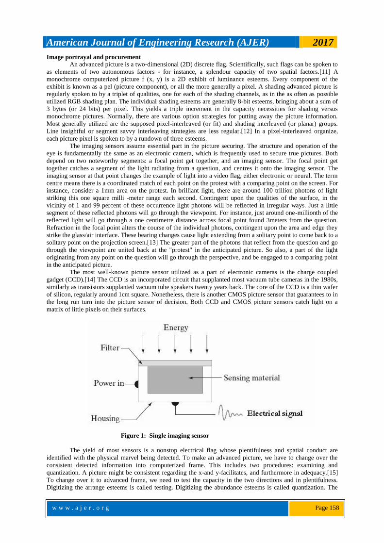
Figure 1: Single imaging sensor
The yield of most sensors is a nonstop electrical flag whose plentifulness and spatial conduct are
identified with the physical marvel being detected. To make an advanced picture, we have to change over the
consistent detected information into computerized frame. This includes two procedures: examining and
quantization. A picture might be consistent regarding the x-and y-facilitates, and furthermore in adequacy.[15]
To change over it to advanced frame, we need to test the capacity in the two directions and in plentifulness.
Digitizing the arrange esteems is called testing. Digitizing the abundance esteems is called quantization. The
American Journal of Engineering Research (AJER) 2017
w w w . a j e r . o r g
Page 159
consequence of testing and quantization is a lattice of genuine numbers. Every component of this network
exhibit is called a picture component, picture component or pixel as was expressed previously. The high contrast
picture sensors and cameras can do this exclusive for the brilliance sensation; the extremely rich impression of
shading requires extra data. For the best execution, a shading camera is worked by giving extraordinary shaft
part optics and by masterminding three highly contrasting picture sensors with the goal that they see an
indistinguishable bit of a scene. Each picture sensor is secured with its own particular shading channel, as
simply portrayed, and together the three picture sensors obtain the total colorimetric data about a scene. Such
three-chip shading cameras are utilized in expert and studio cameras. They are very costly.[16] Therefore, it is
exceptionally attractive to understand a shading camera with only one single highly contrasting picture sensor
and a reasonable example of pixel-singular shading channels to finish everything. Among the most utilized
channels has a place 2-D mosaic shading channel or Bayer design. This sort of picture sensors is for the most
part utilized these days.
Proposed methods for omni-directional vision system
Strong individual following, their head postures, and their personalities are basic for a framework to
give data on who is in the scene, where they are found, what they are doing, who is conversing with whom, and
when associations happen.[17] Omni-directional frameworks serve for recording gatherings, observation,
versatile mechanical autonomy and sensors. A large portion of them are versatile and endure by the vibrations.
Such framework is typically in view of standard camcorder outfitted with a non-planar mirror which is mounted
to the holder. For instance, the normal framework is planned keeping in mind the end goal to be introduced on
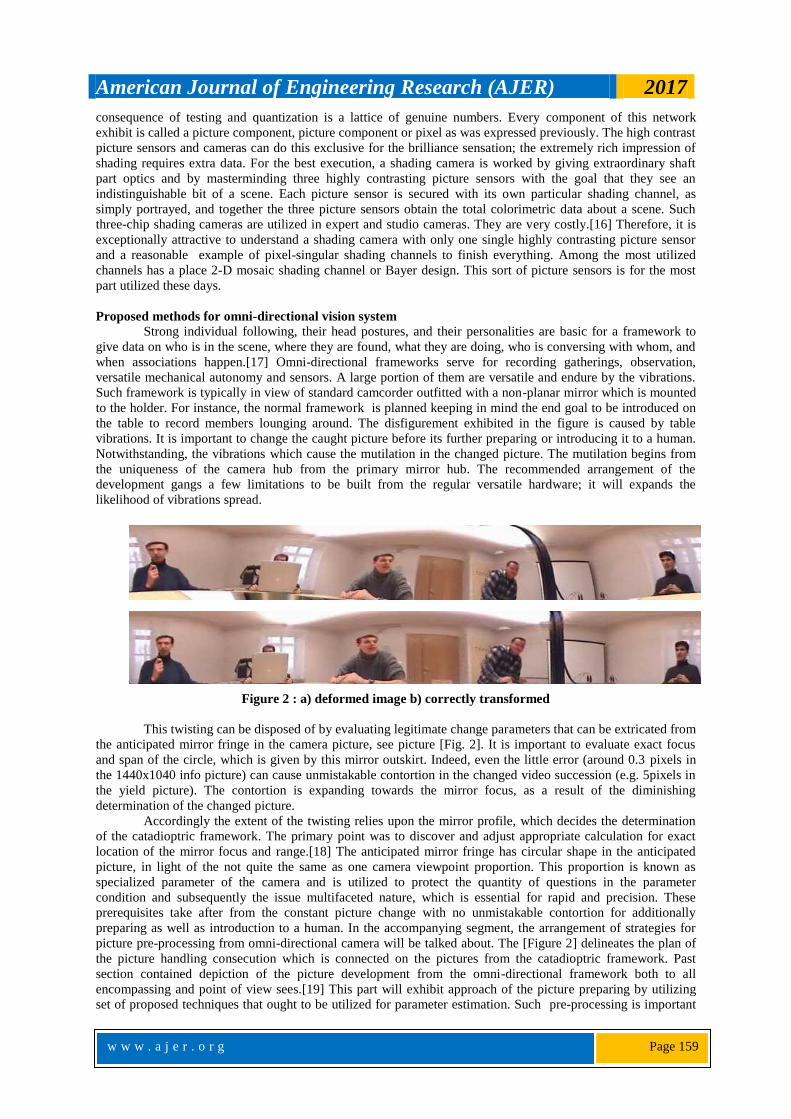
the table to record members lounging around. The disfigurement exhibited in the figure is caused by table
vibrations. It is important to change the caught picture before its further preparing or introducing it to a human.
Notwithstanding, the vibrations which cause the mutilation in the changed picture. The mutilation begins from
the uniqueness of the camera hub from the primary mirror hub. The recommended arrangement of the
development gangs a few limitations to be built from the regular versatile hardware; it will expands the
likelihood of vibrations spread.
Figure 2 : a) deformed image b) correctly transformed
This twisting can be disposed of by evaluating legitimate change parameters that can be extricated from
the anticipated mirror fringe in the camera picture, see picture [Fig. 2]. It is important to evaluate exact focus
and span of the circle, which is given by this mirror outskirt. Indeed, even the little error (around 0.3 pixels in
the 1440x1040 info picture) can cause unmistakable contortion in the changed video succession (e.g. 5pixels in
the yield picture). The contortion is expanding towards the mirror focus, as a result of the diminishing
determination of the changed picture.
Accordingly the extent of the twisting relies upon the mirror profile, which decides the determination
of the catadioptric framework. The primary point was to discover and adjust appropriate calculation for exact
location of the mirror focus and range.[18] The anticipated mirror fringe has circular shape in the anticipated
picture, in light of the not quite the same as one camera viewpoint proportion. This proportion is known as
specialized parameter of the camera and is utilized to protect the quantity of questions in the parameter
condition and subsequently the issue multifaceted nature, which is essential for rapid and precision. These
prerequisites take after from the constant picture change with no unmistakable contortion for additionally
preparing as well as introduction to a human. In the accompanying segment, the arrangement of strategies for
picture pre-processing from omni-directional camera will be talked about. The [Figure 2] delineates the plan of
the picture handling consecution which is connected on the pictures from the catadioptric framework. Past
section contained depiction of the picture development from the omni-directional framework both to all
encompassing and point of view sees.[19] This part will exhibit approach of the picture preparing by utilizing
set of proposed techniques that ought to be utilized for parameter estimation. Such pre-processing is important
American Journal of Engineering Research (AJER) 2017
w w w . a j e r . o r g
Page 160
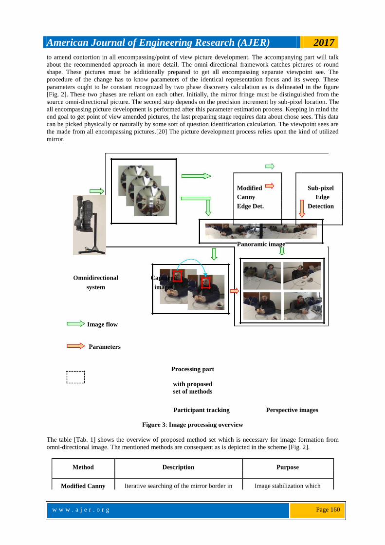
to amend contortion in all encompassing/point of view picture development. The accompanying part will talk
about the recommended approach in more detail. The omni-directional framework catches pictures of round
shape. These pictures must be additionally prepared to get all encompassing separate viewpoint see. The
procedure of the change has to know parameters of the identical representation focus and its sweep. These
parameters ought to be constant recognized by two phase discovery calculation as is delineated in the figure
[Fig. 2]. These two phases are reliant on each other. Initially, the mirror fringe must be distinguished from the
source omni-directional picture. The second step depends on the precision increment by sub-pixel location. The
all encompassing picture development is performed after this parameter estimation process. Keeping in mind the
end goal to get point of view amended pictures, the last preparing stage requires data about chose sees. This data
can be picked physically or naturally by some sort of question identification calculation. The viewpoint sees are
the made from all encompassing pictures.[20] The picture development process relies upon the kind of utilized
mirror.
Modified
Sub-pixel
Canny Edge
Edge Det. Detection
Panoramic image
Omnidirectional Captured
system images
Image flow
Parameters
Processing part
with proposed
set of methods
Participant tracking Perspective images
Figure 3: Image processing overview
The table [Tab. 1] shows the overview of proposed method set which is necessary for image formation from
omni-directional image. The mentioned methods are consequent as is depicted in the scheme [Fig. 2].
Method Description Purpose
Modified Canny Iterative searching of the mirror border in Image stabilization which

American Journal of Engineering Research (AJER) 2017
w w w . a j e r . o r g
Page 161
edge detection the captured image by using one removes the distortion in the
directional edge detection approach video sequence and
automatic initialization of
Sub-pixel edge Additive method for increasing of the
transformation
detection accuracy of parameter estimation
Panoramic Transformation of the captured image The 360 degree image
image formation into the panoramic view by using
estimated parameters
Perspective Virtual view selection and perspective Generating of perspective
image formation Correction images as from classical
cameras
Table 1: Description of the set of methods used for omni-directional image Pre-processing
From the earlier learning around an omni-directional picture permits us utilize particular strategies for
circle discovering, which speaks to the anticipated mirror fringe. It is important to assess all hover parameters
toward the start. At that point, the circle span is consistent and the inside fluctuates in limit interim.[21] The
reasonable determination and the proposal strategies influence a few properties. The more imperative of these
are appearance of just a single hover in the picture and conceivable incomplete hover editing by the picture
fringe and event of spurious edges. There are likewise a few reasons for error in finding the focal point of circle:
• natural edge width may add mistakes to any assessments of the area of the inside,
• image commotion may make the outspread position of the edge end up plainly changed,
• image clamour may cause variety in the appraisals of nearby edge introduction,
• an object(edge) may seem mutilated in view of brightening.
Various strategies for oval individual circle recognition exist. Some of them, which can be utilized to
tackle such issue, are referred. Precision and speed of the calculation are the most focused on components.
Thusly the present calculations are unsuitable. Among the notable techniques has a place the Hough change or
RANSAC calculation. The Hough change is extremely strong strategy to identify different highlights including
circles. Then again, this strategy is computationally expensive, which limits its utilization in such issues. Every
one of these techniques has been actualized and tried to get similar outcomes with proposed technique. These
outcomes are expressed.[23] These perspectives require the outline of novel approach for discovery of the
mirror fringe with given properties.
Accomplishment of Objectives
This depicts proposed strategies, which make the arrangement of techniques required for all
encompassing/viewpoint picture development from omni-directional framework. The strategy configuration
comes about because of the plan [Fig. 2] that was proposed in the beginning of our research work.
Parameter estimation of the mirror projection The point was to create straightforward and quick calculation for sub-pixel reflect edge recognition and
parameter estimation. Since the edge of the mirror is obvious in the picture, the central point can without much
of a stretch be evaluated by fitting a circle to the picture of the mirror edge.[22] The focal point of the identical
representation can be viewed as the central point. Some of existing strategies were tried, however they don't
fulfil the speed or exactness requirements. The proposed technique ought to have the capacity to work
progressively; it implies finding exact parameters for each casing in the video grouping. The second measure is
high exactness of the distinguished parameters, particularly focus directions of the perfect representation. The
normal precision ought to be lower than 0.2 pixels by reason of the contortion disposal. The reason, why we
need such discovery calculation, is that there exist a great deal of recorded video-groupings with jumbled
foundation behind the perfect representation and furthermore with no noteworthy imprints for the alignment.
The principle thought is to extricate reflect outskirt pixels. Removed outskirt pixels serve for parameter
calculation by utilizing iterative direct relapse technique. The requirements are n measured focuses with xi , yi

American Journal of Engineering Research (AJER) 2017
w w w . a j e r . o r g
Page 162
organizes and the yield is the centre of the circle x0 , y0 and the sweep r. The technique ought to have the
capacity to discover all mirror parameters including range, since it is obscure toward the start of the adjustment
and change process. The middle directions estimation is sufficient for whatever remains of the video-
arrangement. In the accompanying sections, the circle identification process will be displayed. These techniques
were distributed by this creator on the VIIP 2005 gathering. [5]
One-directional edge recognition
The essential approach for edge identification is utilizing reasonable convolution veils. These basic
edge locators contrast in their frame and quality. There are a few models, which we are anticipating from the
edge location. To begin with standard stipulates that edges happening in pictures ought not be missed and that
there ought to be no reactions to non-edges. The second rule is that the edge indicates are be all around
confined. At the end of the day, the separation between the edge pixels as found by the identifier and the real
edge is to be at the very least.[25] A third measure is to have just a single reaction to a solitary edge. This is
required in light of the fact that the initial two paradigms were not sufficiently generous to totally kill the
likelihood of different reactions to an edge. These criteria fulfill the outstanding Canny edge identifier from
which the proposed technique emerges.
An earlier learning around a picture let us utilize particular strategies for circle finding. It isn't
important to scan entire picture space for conceivable circles. The span and furthermore the focal point of the
hover shift in a thin interim. It permits particular of the picked interim of these parameters for seeking circle in
the picture.[24] The primary thought is to smoother edges that are not parallel with the plausible mirror fringe.
Thusly, just the angle with vertical bearing in regards to the mirror span is utilized for this reason. So for basic
application, the picture part around the likely mirror outskirt must be rectified. The basic change portrayed is
appropriate for this reason. State of the changed picture is rectangular and outskirt of the circle is changed as a
line in perfect case. This empowers us to utilize traditional veil edge indicator for even edge reaction.
Figure 3: Left - transformed part of the image and image after application of the one-directional edge
detector, Right - iterative process with modified canny edge detection
The underlying parameters, which are required for assurance of the territory measure, are evaluated
from the gathered perfect representation position and size. The understood perfect representation position is
precisely in the focal point of the picture caught from the omni-directional framework, on the grounds that the
identical representation should cover the greatest piece of the caught picture and ought to fulfill the hub
fortuitous event. Concerning nature of the caught pictures as far as possible for the recognized parameters were
found:
• Position of the inside x-arrange can be ±30% of the picture width.

American Journal of Engineering Research (AJER) 2017
w w w . a j e r . o r g
Page 163
• Position of the inside y-arrange can be ±30% of the picture tallness.
• Radius size can be ±40% of the picture stature.
These impediments can be balanced with greater extents. The further preferred standpoint of this
change for edge identification is a decision of the picture determination from which edges will be removed. The
subsequent changed picture can have different amounts of sections that speak to vertical lines spreading over to
the mirror fringe. The lower number of vertical sections can build the speed of the calculation. Be that as it may,
it is important to keep up the coveted precision, which was tried and talked about in the part 5.4. This approach
likewise empowers basically remove only one edge point with edge reaction parallel to the plausible mirror
outskirt, which lies on the span line of this fringe.
In light of the criteria depicted over, the changed shrewd edge identifier first smoothes the picture to
wipe out a clamour. The Gaussian channel is utilized only to smooth the picture, since it can be processed
utilizing a straightforward cover with successful usage. The correct size of the Gaussian cover must be picked,
in light of the fact that it influences the affectability of the edge finder to clamour and furthermore restriction
mistake. Both are expanding with the cover measure. In the wake of smoothing the picture and wiping out the
clamour, the subsequent stage is to discover the edge quality by taking the inclination of the picture. The
primary distinction with traditional Canny edge discovery is that lone the inclination for flat edge location is
utilized:
The initial parameters, which are needed for determination of the area size, are estimated from the
supposed mirror image position and size. The implicit mirror image position is exactly in the centre of the image
captured from the omni-directional system, because the mirror image should cover the biggest part of the
captured image and should satisfy the axis coincidence. Regarding the nature of the captured images the
following limits for the detected parameters were deduced:
Position of the centre x-coordinate can be ±30% of the image width.
Position of the centre y-coordinate can be ±30% of the image height.Radius size can be ±40% of the
image height. These limitations can be adjusted with bigger ranges, which were tested in research paper. The
further advantage of this transformation for edge detection is a choice of the image resolution from which edges
will be extracted. The resulting transformed image can have various quantities of columns that represent vertical
lines spanning to the mirror border. The lower number of vertical columns can increase the speed of the
algorithm. However, it is necessary to maintain the desired accuracy, which was tested and discussed in the
chapter 5.4. This approach also enables simply extract just one edge point with edge response parallel to the
probable mirror border, which lies on the radius line of this border.
Based on the criteria described above, the modified canny edge detector first smoothes the image to
eliminate a noise. The Gaussian filter is used exclusively to smooth the image, because it can be computed using
a simple mask with effective implementation. The proper size of the Gaussian mask must be chosen, because it
affects the sensitivity of the edge detector to noise and also localization error. Both are increasing with the mask
size. After smoothing the image and eliminating the noise, the next step is to find the edge strength by taking the
gradient of the image.
The first difference with classical Canny edge detection is that only the gradient for horizontal edge detection is
used:
G hy (1)
The image gradient is used to highlight regions with high spatial derivatives in vertical direction. The further
important information is the direction of the detected edge, which will serve for non-maxima suppression. This
direction is computed from responses of the vertical and horizontal edge detection mask:
Phase a tan(hy / hx ) (2)
Once the edge direction is known, the next step is to relate the edge direction to a direction that can be
traced in an image. Only four possible directions are enabled there. When the edge directions are known, non-
maximum suppression has to be applied. This method is used to trace along the edge in the edge direction and
suppress any pixel value (sets it equal to 0) that is not considered to be an edge. This will give a thin line in the
gradient image. The second modification of the classical Canny edge detector is additional suppressing of the

American Journal of Engineering Research (AJER) 2017
w w w . a j e r . o r g
Page 164
edges with 90 and 270 degrees direction. The gradient image is now further reduced by hysteresis. Hysteresis is
used to track along the remaining pixels that have not been suppressed. It uses two thresholds and if the
magnitude is below the first threshold, it is set to zero (made a non-edge). If the magnitude is above the high
threshold, it is made an edge. Then, any pixels that are connected to this edge pixel and that have a value greater
than low threshold are also selected as edge pixels.
American Journal of Engineering Research (AJER) 2017
w w w . a j e r . o r g
Page 165
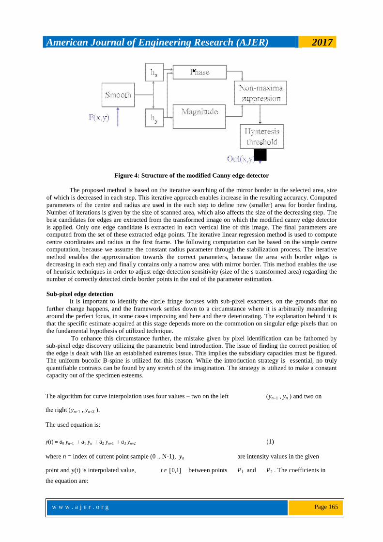
Figure 4: Structure of the modified Canny edge detector
The proposed method is based on the iterative searching of the mirror border in the selected area, size
of which is decreased in each step. This iterative approach enables increase in the resulting accuracy. Computed
parameters of the centre and radius are used in the each step to define new (smaller) area for border finding.
Number of iterations is given by the size of scanned area, which also affects the size of the decreasing step. The
best candidates for edges are extracted from the transformed image on which the modified canny edge detector
is applied. Only one edge candidate is extracted in each vertical line of this image. The final parameters are
computed from the set of these extracted edge points. The iterative linear regression method is used to compute
centre coordinates and radius in the first frame. The following computation can be based on the simple centre
computation, because we assume the constant radius parameter through the stabilization process. The iterative
method enables the approximation towards the correct parameters, because the area with border edges is
decreasing in each step and finally contains only a narrow area with mirror border. This method enables the use
of heuristic techniques in order to adjust edge detection sensitivity (size of the s transformed area) regarding the
number of correctly detected circle border points in the end of the parameter estimation.
Sub-pixel edge detection
It is important to identify the circle fringe focuses with sub-pixel exactness, on the grounds that no
further change happens, and the framework settles down to a circumstance where it is arbitrarily meandering
around the perfect focus, in some cases improving and here and there deteriorating. The explanation behind it is
that the specific estimate acquired at this stage depends more on the commotion on singular edge pixels than on
the fundamental hypothesis of utilized technique.
To enhance this circumstance further, the mistake given by pixel identification can be fathomed by
sub-pixel edge discovery utilizing the parametric bend introduction. The issue of finding the correct position of
the edge is dealt with like an established extremes issue. This implies the subsidiary capacities must be figured.
The uniform bucolic B-spine is utilized for this reason. While the introduction strategy is essential, no truly
quantifiable contrasts can be found by any stretch of the imagination. The strategy is utilized to make a constant
capacity out of the specimen esteems.
The algorithm for curve interpolation uses four values – two on the left yn1 , yn and two on
the right yn1 , yn2 .
The used equation is:
y(t) a0 yn1 a1 yn a2 yn1 a3 yn2 (1)
where n = index of current point sample (0 .. N-1), yn are intensity values in the given
point and y(t) is interpolated value, t 0,1 between points P1 and P2 . The coefficients in
the equation are:

American Journal of Engineering Research (AJER) 2017
w w w . a j e r . o r g
Page 166
a0
t 3 3t
2 3t 1
(2)
6
a
3t 3 6t
2 4
(3)
1
6
a2
3t 3 3t
2 3t 1
(4)
6
a3 t 3
(5)
6
Our aim is to find such position on the interpolated curve, where the gradient is going to decrease after
increasing or it is going to increase after decreasing (the second derivative changes sign). This kind of points can
be found on the places with zero second derivation. This condition does not guarantee the proper edge location,
because it can be local maxima or minima. Therefore, we will search the point with zero second derivation and
maximal first derivation. Firstly, the position of the zero second derivation must be computed. The point,
where is the second derivation equals the zero, is called point of inflexion.
2 y(t)
(t 1) y n1 (3t 2) yn (3t 1) yn1 tyn2 (6)
2
t
Then, we state the condition
2 y(t)
0 ,
(7)
2 t
from which the following position t is derived
t
2 yn yn1
yn1
. (8)
yn1 3 yn 3yn1 yn2
The value t with the first derivative gives us the information about the edge slope which is necessary for the
selection of the best edge. The equation for the first derivation is
y(t)
3t 2 6t 3
yn1
9t 2 12t
yn
9t 2 6t 3
yn1
3t 2
yn2 (9)
6
6
t 6 6
The direction of the curve for which the edge is computed must be coincident with the radius of the tested circle
(see Fig. 3left). This line intersects horizontal/vertical curves, which are also interpolated from pixel values (see
Fig. 3 right) in the raster image.
American Journal of Engineering Research (AJER) 2017
w w w . a j e r . o r g
Page 167
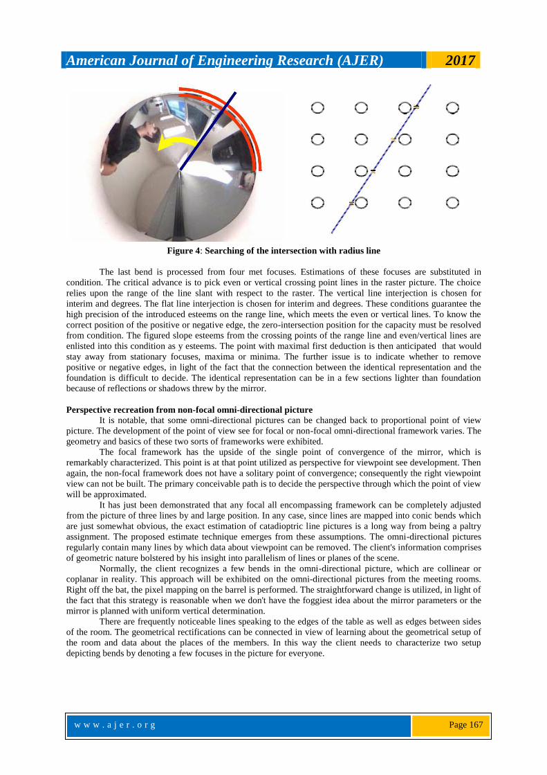
Figure 4: Searching of the intersection with radius line
The last bend is processed from four met focuses. Estimations of these focuses are substituted in
condition. The critical advance is to pick even or vertical crossing point lines in the raster picture. The choice
relies upon the range of the line slant with respect to the raster. The vertical line interjection is chosen for
interim and degrees. The flat line interjection is chosen for interim and degrees. These conditions guarantee the
high precision of the introduced esteems on the range line, which meets the even or vertical lines. To know the
correct position of the positive or negative edge, the zero-intersection position for the capacity must be resolved
from condition. The figured slope esteems from the crossing points of the range line and even/vertical lines are
enlisted into this condition as y esteems. The point with maximal first deduction is then anticipated that would
stay away from stationary focuses, maxima or minima. The further issue is to indicate whether to remove
positive or negative edges, in light of the fact that the connection between the identical representation and the
foundation is difficult to decide. The identical representation can be in a few sections lighter than foundation
because of reflections or shadows threw by the mirror.
Perspective recreation from non-focal omni-directional picture
It is notable, that some omni-directional pictures can be changed back to proportional point of view
picture. The development of the point of view see for focal or non-focal omni-directional framework varies. The
geometry and basics of these two sorts of frameworks were exhibited.
The focal framework has the upside of the single point of convergence of the mirror, which is
remarkably characterized. This point is at that point utilized as perspective for viewpoint see development. Then
again, the non-focal framework does not have a solitary point of convergence; consequently the right viewpoint
view can not be built. The primary conceivable path is to decide the perspective through which the point of view
will be approximated.
It has just been demonstrated that any focal all encompassing framework can be completely adjusted
from the picture of three lines by and large position. In any case, since lines are mapped into conic bends which
are just somewhat obvious, the exact estimation of catadioptric line pictures is a long way from being a paltry
assignment. The proposed estimate technique emerges from these assumptions. The omni-directional pictures
regularly contain many lines by which data about viewpoint can be removed. The client's information comprises
of geometric nature bolstered by his insight into parallelism of lines or planes of the scene.
Normally, the client recognizes a few bends in the omni-directional picture, which are collinear or
coplanar in reality. This approach will be exhibited on the omni-directional pictures from the meeting rooms.
Right off the bat, the pixel mapping on the barrel is performed. The straightforward change is utilized, in light of
the fact that this strategy is reasonable when we don't have the foggiest idea about the mirror parameters or the
mirror is planned with uniform vertical determination.
There are frequently noticeable lines speaking to the edges of the table as well as edges between sides
of the room. The geometrical rectifications can be connected in view of learning about the geometrical setup of
the room and data about the places of the members. In this way the client needs to characterize two setup
depicting bends by denoting a few focuses in the picture for everyone.

American Journal of Engineering Research (AJER) 2017
w w w . a j e r . o r g
Page 168
Figure 5: Part of transformed image together with alignment for equalization
These curves are approximated by circles or other conics, which depends on the type of used mirror. These
curves are used to make pixel interpolations to solve deformations in the vertical direction. This interpolation is
linear in the case of figure 6.
Figure 6: Equalized image
The mirror profile course can be used to define the interpolation to decrease deformation caused by
mirror profile. Because the panoramic image is used, the distortion in the horizontal direction can be computed
by perspective equation (20) The comparison between this kind of perspective image formation and image
formation by using virtual viewpoint is presented in the chapter 5.3. This method was published on ICPR 2004
conference and was used for omni-directional image pre-processing for face tracking system based on the
particle filter.
II. EXPERIMENTS AND RESULTS Two types of mirrors were available for testing of proposed set of methods. Both were provided by
company Neovision. Both mirrors have diameter 60mm and are made from glass with metallic coating. The first
H3G mirror has “universal” profile shape defined by hyperbolic equation:
z 2
x 2 y
2
1 (1)
789,3274
548,1440
The second mirror was custom-made with predefined parameters, the most important was constant vertical
resolution in 1m distance from the main mirror axis. This mirror was specially developed for meeting recording
purposes, where such property is important.
Figure 7: a) H3G mirror b) mirror with constant vertical resolution

American Journal of Engineering Research (AJER) 2017
w w w . a j e r . o r g
Page 169
Both mirrors are rotationally symmetric, which allows capturing a 360 degrees view around the main axis. The
vertical view angle is about 105 degrees. Profiles of both mirrors are depicted in picture.
Figure 8: a) hyperbolic mirror H3G b) custom-made mirror
The two mirrors are utilized with standard point of view cameras. Mirrors can be mounted on the
mirror holder in particular position towards to a camera which fullfills the happenstance of the mirror hub with
the fundamental camera hub. For this reason, the mirror holder MH1 was utilized. The framework configuration
is normally utilized for corpus recording of live gatherings with four members lounging around.
Simple versus geometric change The correlation of the straightforward unwrapping and geometrical change with the tried picture
demonstrates the twisting in vertical pivot of the yield picture. Since the mirrors are rotationally symmetric, the
level bending attributable to reflect shape don't happens. The manufactured picture, which contains flat lines
with steady separation between them, was utilized for tests.
This picture was caught by utilizing hyperbolic mirror H3G with profile delineated on the picture and it
is changed by utilizing two sorts of change techniques. The straightforward unwrapping strategy does not
consider the mirror profile. Hence, the changed picture is vertically misshaped, which is exhibited by various
separations between lines in the picture. Contrasted with the geometrical change, the level lines are effectively
changed with consistent separation. The second distinction is exhibited by the determination movement in the
vertical bearing. This test demonstrates that the H3G reflect has not consistent vertical determination, which was
characterized in the segment. Such property isn't appropriate for utilizing mirror with this profile for catching of
the gatherings, since generally consistent determination in the vertical hub is required.
Figure: 9 a) omni-directional image from H3G mirror b) geometrically transformed image c) simple
unwrapped image
American Journal of Engineering Research (AJER) 2017
w w w . a j e r . o r g
Page 170
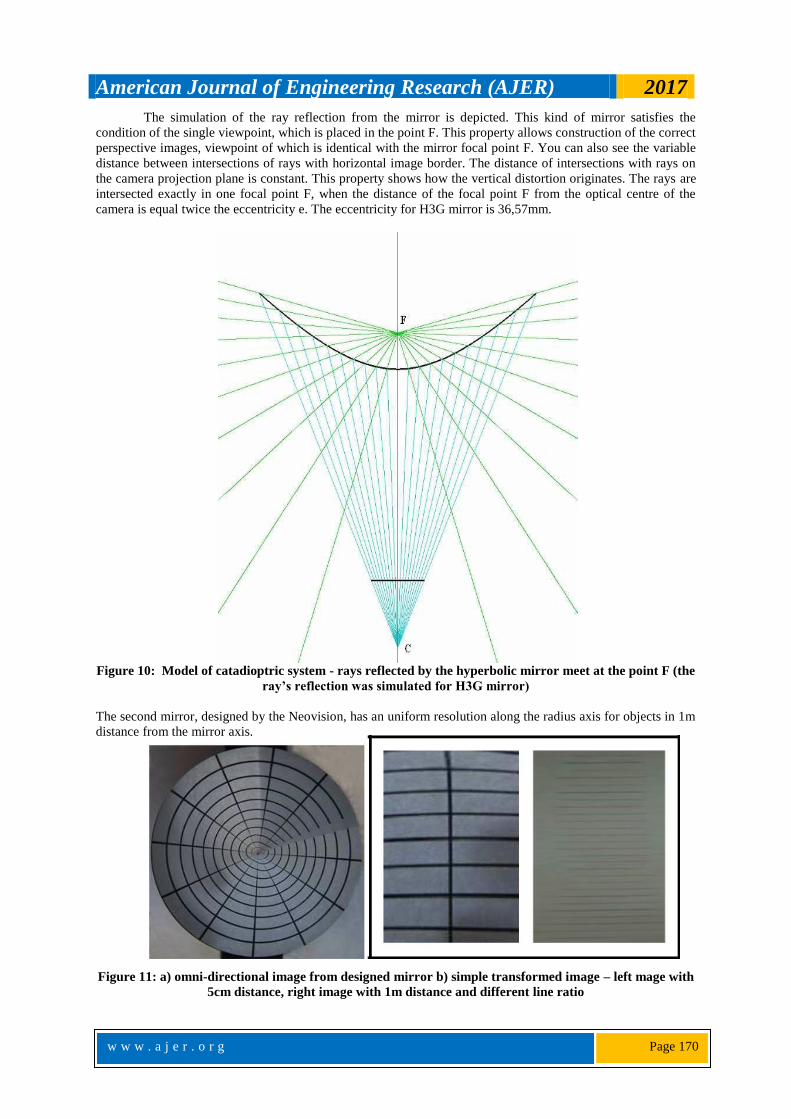
The simulation of the ray reflection from the mirror is depicted. This kind of mirror satisfies the
condition of the single viewpoint, which is placed in the point F. This property allows construction of the correct
perspective images, viewpoint of which is identical with the mirror focal point F. You can also see the variable
distance between intersections of rays with horizontal image border. The distance of intersections with rays on
the camera projection plane is constant. This property shows how the vertical distortion originates. The rays are
intersected exactly in one focal point F, when the distance of the focal point F from the optical centre of the
camera is equal twice the eccentricity e. The eccentricity for H3G mirror is 36,57mm.
Figure 10: Model of catadioptric system - rays reflected by the hyperbolic mirror meet at the point F (the
ray’s reflection was simulated for H3G mirror)
The second mirror, designed by the Neovision, has an uniform resolution along the radius axis for objects in 1m
distance from the mirror axis.
Figure 11: a) omni-directional image from designed mirror b) simple transformed image – left mage with
5cm distance, right image with 1m distance and different line ratio
American Journal of Engineering Research (AJER) 2017
w w w . a j e r . o r g
Page 171
A steady determination can be precisely accomplished just at same separation from the rotational
mirror pivot and hence the indicated pictures may not present precisely consistent determination as the
separation of the matrix is around 5cm from the mirror hub while the separation for which the genuinely
consistent determination ought to be acquired is 1meter.Distortion emerges from a parallax impact, where the
perspective does not remain steady with rise point. This impact is generally unmistakable when the point of
view picture is made, that will be exhibited in the passage.
Separation impact
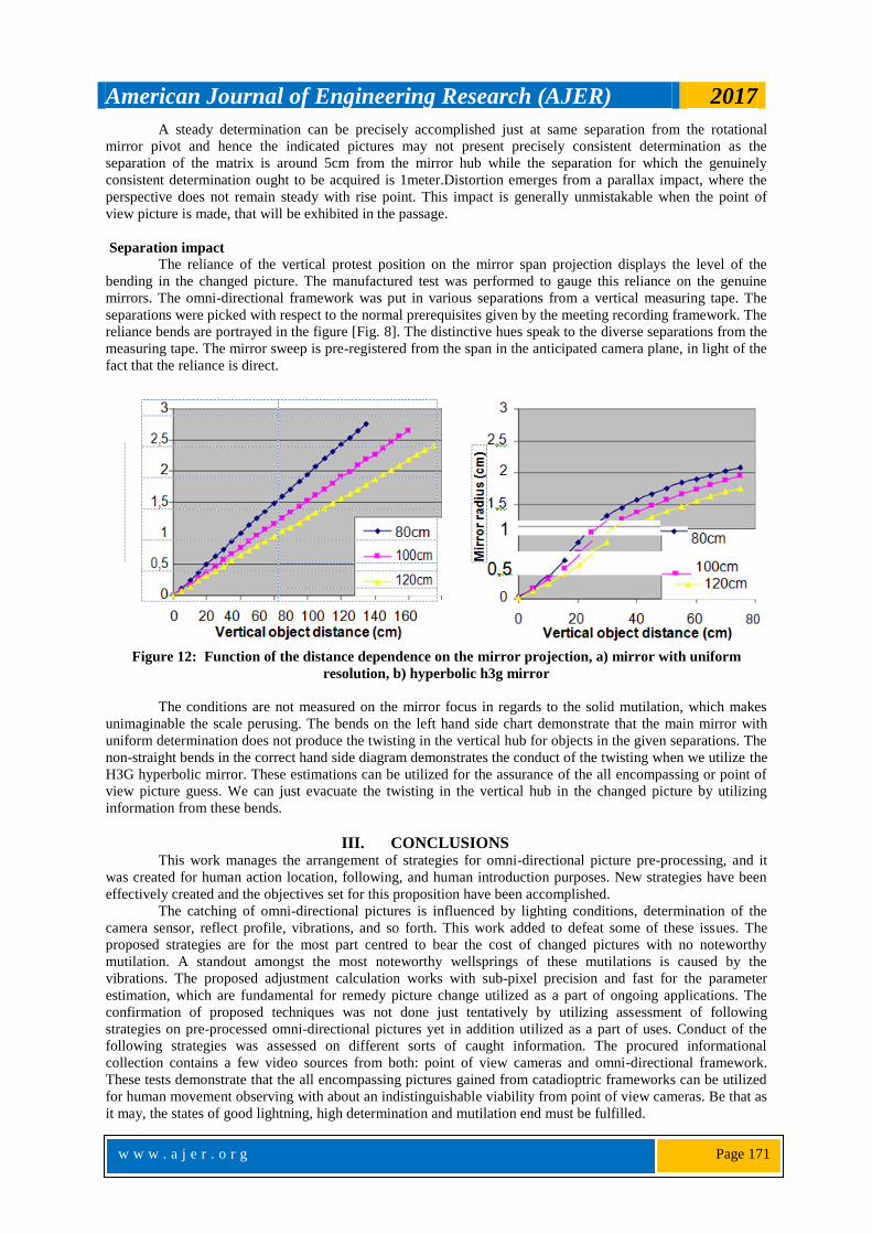
The reliance of the vertical protest position on the mirror span projection displays the level of the
bending in the changed picture. The manufactured test was performed to gauge this reliance on the genuine
mirrors. The omni-directional framework was put in various separations from a vertical measuring tape. The
separations were picked with respect to the normal prerequisites given by the meeting recording framework. The
reliance bends are portrayed in the figure [Fig. 8]. The distinctive hues speak to the diverse separations from the
measuring tape. The mirror sweep is pre-registered from the span in the anticipated camera plane, in light of the
fact that the reliance is direct.
Figure 12: Function of the distance dependence on the mirror projection, a) mirror with uniform
resolution, b) hyperbolic h3g mirror
The conditions are not measured on the mirror focus in regards to the solid mutilation, which makes
unimaginable the scale perusing. The bends on the left hand side chart demonstrate that the main mirror with
uniform determination does not produce the twisting in the vertical hub for objects in the given separations. The
non-straight bends in the correct hand side diagram demonstrates the conduct of the twisting when we utilize the
H3G hyperbolic mirror. These estimations can be utilized for the assurance of the all encompassing or point of
view picture guess. We can just evacuate the twisting in the vertical hub in the changed picture by utilizing
information from these bends.
III. CONCLUSIONS This work manages the arrangement of strategies for omni-directional picture pre-processing, and it
was created for human action location, following, and human introduction purposes. New strategies have been
effectively created and the objectives set for this proposition have been accomplished.
The catching of omni-directional pictures is influenced by lighting conditions, determination of the
camera sensor, reflect profile, vibrations, and so forth. This work added to defeat some of these issues. The
proposed strategies are for the most part centred to bear the cost of changed pictures with no noteworthy
mutilation. A standout amongst the most noteworthy wellsprings of these mutilations is caused by the
vibrations. The proposed adjustment calculation works with sub-pixel precision and fast for the parameter
estimation, which are fundamental for remedy picture change utilized as a part of ongoing applications. The
confirmation of proposed techniques was not done just tentatively by utilizing assessment of following
strategies on pre-processed omni-directional pictures yet in addition utilized as a part of uses. Conduct of the
following strategies was assessed on different sorts of caught information. The procured informational
collection contains a few video sources from both: point of view cameras and omni-directional framework.
These tests demonstrate that the all encompassing pictures gained from catadioptric frameworks can be utilized
for human movement observing with about an indistinguishable viability from point of view cameras. Be that as
it may, the states of good lightning, high determination and mutilation end must be fulfilled.
American Journal of Engineering Research (AJER) 2017
w w w . a j e r . o r g
Page 172
Unique commitments of this work
The principle objective of this work was to create reasonable arrangement of strategies expected to
limit the twisting in the changed pictures in order to be material for human introduction and following purposes.
To accomplish this objective the accompanying advances were accomplished:
• The catadioptric picture arrangement was examined and conceivable outcomes of picture change into the all
encompassing or point of view see were portrayed. Alteration of the current techniques for point of view
change from non-focal omni-directional framework was recommended.
• The adjustment calculation was created to accomplish sub-pixel precision while keeping the high preparing
speed. The proposed techniques contain two sections: the first can recognize introductory position of the
mirror outskirt and the second strategy serves for parameter change by means of utilizing sub-pixel
recognition. This handling stage is the important advance in catadioptric picture arrangement when
vibrations are available.
The assessment conspire was set up and the informational index containing both point of view and
omni-directional video arrangements were procured to for all intents and purposes demonstrate the downsides
and additionally benefits. This plan was utilized for assessment of two following techniques on various video
sources. Alleged portable meeting room was produced for a reasonable assessment of proposed approaches.
This framework containing composed strategies was exhibited in the few outside occasions as CeBit 2006 in
Hannover, Wain house Research Forum in Berlin, MLMI Conference in Washington and other.
IV. FUTURE WORK The most noteworthy favourable position of catadioptric frameworks is in a vast field of view with no
moving parts. A few PC applications profits by this favourable position and along these lines it is attractive to
centre the examination into this territory. A great deal of issues important to the omni-directional vision still
exist. These issues hint the method for the continuation the future work. One of them is the lighting that
influences the framework from various sides. The lighting cases to impact investigation of the diverse
conditions and the strategies for adjustments that are inclined to lighting conditions have been recommended.
One of the fascinating ranges is the skin shading investigation for human body parts identification. This
component is influenced by various lighting conditions from various lightning sources, which influence the
omni-directional framework significantly more than established cameras with limit field of view.
The assortment of mirror profiles offers the new territory of the framework plans with particular
necessities on the field of view and nature of the picture parts. These properties require adjustments of existing
techniques for picture handling with a specific end goal to accomplish reasonable outcomes. Mirrors with non-
focal perspective are utilized in light of their particular properties. Then again, since they have non-focal
perspective, particular requests to plan strategies for rectify picture arrangement or 3D point assurance would be
required. These strategies for viewpoint/all encompassing picture development can be assessed by an
indistinguishable way from our proposed research work.
The further research zone related with legitimate 3D point assurance could be gone for programmed
camera introduction in the picked condition by utilizing omni-directional frameworks. However another
fascinating region contains hostile to associating strategies, which ought to be produced to remedy picture
arrangement, on the grounds that the pixels which are changed from the camera picture does not compare
precisely "one to on e" to the pixels of the anticipated picture.
REFERENCES [1] Jones, M., Rehg, J.: Statistical Color Models with Application to Skin Detection, Cambridge Research Laboratory, Computer
Vision and Pattern Recognition (CVPR99), Ft.Collins, CO, 274-280, June, 1999.
[2] Kruppa, H., Bauer, M., Schiele, B., Skin Patch Detection in Real-World Images, Perceptual Computing and Computer Vision
Group, ETH Zurich, Schwitzerland, 2002.
[3] Martinkauppi, J., Soriano, M., Laaksonen, M., Behavior of skin color under varying illumination seen by different cameras at different color spaces, Proc. SPIE Vol. 4301 Machine Vision in Industrial Inspection IX, January 19-26, San Jose California.
[4] Stoerring, M., Granum, E., Constraining a statistical skin colour model to adapt to illumination changes, In 7th German Workshop
on Colour Image Processing, pages 47-58, Erlangen-Nuernberg, Germany, October 4-5, 2001. [5] Vezhnevets, V.: Method for Localization of Human Faces in Color-Based Face Detectors and Trackers, Department of
Computational Mathematics & Cybernetics, Moscow State University, Vorobjovy Gory, Russia, 2001.
[6] Geusebroek, J., Smeulders, A., Color constancy from physical principles, Pattern Recognition Letters 24, p. 1653–1662, year 2003. [7] Yang, G., Huang, T.: Human face detection in complex background, Pattern recognition, 27(1):53-63, 1994.
[8] Yang, Y., Waibel, A., A real-time face tracker, Proceedings of the 3rd IEEE Workshop on Applications of Computer Vision
(WACV '96), ISBN 0-8186-7620-5, 1996. [9] Terrillon, J., Akamatsu, S., Comparative Performance of Different Chrominance Spaces for Color Segmentation and Detection of
Human Faces in Complex Scene Images, Vision Interface '99, Trois-Rivières, Canada, 19-21 May.
[10] Augusteijn, M., Skujca, T.: Identification human faces through texture-based feature recognition and neural network technology. In Proceedings of IEEE Conference on Neural Networks, pages 392-398, 1993.
[11] Yow, K., Cipolla, R.: Feature-based human face detection, Image an Vision Computing, 15(9):713-735, 1997.

American Journal of Engineering Research (AJER) 2017
w w w . a j e r . o r g
Page 173
[12] Craw, I., Ellis, H., Lishman, J.: Automatic extraction of face features. Pattern Recognition Letters, 5:183-187, 1987. [13] Schneiderman, H., Kanade, T.: A statistical method for 3D object detection applied to faces and cars, In Proceedings IEEE
Conference on Computer Vision and Pattern Recognition, 2000.
[14] Svoboda, T.: Central Panoramic Cameras Design, Geometry, Egomotion, Center for Machine Perception, Faculty of Electrical Engineering, Czech Technical University, September 30, 1999.
[15] Paletta, L., Frintrop, S., Hertzberg, J., Robust localization using context in omnidirectional imaging, In: 2001 IEEE Intl. Conf. on
Robotics and Automation (ICRA 2001) (May 21-26, 2001, Seoul, Korea), pp. 2072-2077. [16] Jones, M., Rehg, J.: Statistical Color Models with Application to Skin Detection, Cambridge Research Laboratory, Computer
Vision and Pattern Recognition (CVPR99), Ft.Collins, CO, 274-280, June, 1999.
[17] Gaspar, J., Decco, C., Okamoto, J., Santos-Victor, J., Constant Resolution Omnidirectional Cameras, Proceedings of the Third Workshop on Omnidirectional Vision (OMNIVIS’02), 2002.
[18] Eiserloh, P.: An Introduction to Kalman Filters and Applications, Assault and Special Projects Naval Air Warfare Center, China Lake, 2002.
[19] Nayar, S., Baker, S., A Theory of Catadioptric Image Formation, Department of Computer Science, Columbia university, Technical
Report CUCS-015-97. [20] Swaminathan, R., Grossberg, M., Nayar, S., Non-Single Viewpoint Catadioptric Cameras: Geometry and Analysis, Department of
Computer Science, Columbia University, New York, technical report, 2001.
[21] Svoboda, T., Pajdla, T., Hlavac, V., Epipolar Geometry of Panoramic Cameras, In fifth European Conference on Computer Vision, Freiburg, Germany, pages 218 – 232, June 1998.
[22] Pajdla, T., Roth, H., Panoramic imaging with SVAVISCA camera – simulations and reality, research report of the project
OMNIVIEWS No. 1999-29017, October, 2000. [23] Micusik, B., Pajdla, T., Autocalibration & 3D Reconstruction with Non-central Catadioptric Cameras, IEEE Computer Society
Conference on Computer Vision and Pattern Recognition (CVPR'04), Volume 1, pp. 58-65, 2004.
[24] Decco, C., Santos-Victor, J., Gaspar, J., Winters, N., Mirror Design: Principles and Tools, Omniviews Review Meeting, Instituto Superior Tecnico, Lisbon, Portugal, September 2001.
[25] Ishiguro, H., Development of Low-Cost Compact Omnidirectional Vision Sensors and their Applications, Department of Electrical
& Computer Engineering, University of California, San Diego, 1998.
Dr.Vignesh Janarthanan Proposal of a Novel Approach for Stabilization of the Image from
Omni-Directional System in the case of Human Detection & Tracking.” American Journal of
Engineering Research (AJER), vol. 6, no. 11, 2017, pp. 155-173.