Embed Size (px)
Citation preview
Proposal for ISO/IEC SC24 Technical Report:
CAD-to-X3D Conversion for Product Structure, Geometry Representation and Metadata
Hyokwang Lee and Don BrutzmanWeb3D Korea Chapter / Web3D CAD Working Group
2018. 1. 13.
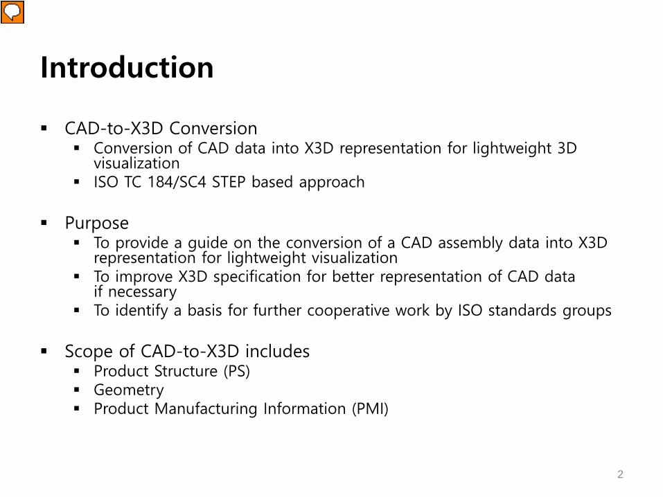
Introduction
CAD-to-X3D Conversion Conversion of CAD data into X3D representation for lightweight 3D
visualization ISO TC 184/SC4 STEP based approach
Purpose To provide a guide on the conversion of a CAD assembly data into X3D
representation for lightweight visualization To improve X3D specification for better representation of CAD data
if necessary To identify a basis for further cooperative work by ISO standards groups
Scope of CAD-to-X3D includes Product Structure (PS) Geometry Product Manufacturing Information (PMI)
2

PSPRODUCT STRUCTURE
3

Representation of PS in STEP*
Representation of PS in an assembly with external reference Assembly and part geometries in the same file An assembly file with external reference to geometry files
=> external reference An assembly file with externally referenced sub-assemblies and
geometry files => nested external reference
4* STEP AP242 Project, http://www.ap242.org/geometry-assembly-pmi-interoperability

* ISO 10303 STEP (Standard for the Exchange of Product) Model Data** Cho, G., Hwang, J., and Kim, Y., "Translation of 3D CAD Data to X3D Dataset Maintaining the Geometry and Structure Information of
a Product.“ The Transactions of the Korea Information Processing Society, VOL. 18-A, NO. 03, PP. 0081~0092, June 2011.
Extraction of PS Information
STEP AP203ed2 instance diagram for PS
STEP*-based approach for extraction of PS information**
5

CAx- and PDM-IF Recommended Practices for External References*
Instance diagram for external references
Extraction of PS Information
* Recommended Practices for External References with References to the PDM Schema Usage Guide, Release 2.1, CAx ImplementationForum and PDM Implementation Forum, January 19, 2005.
6
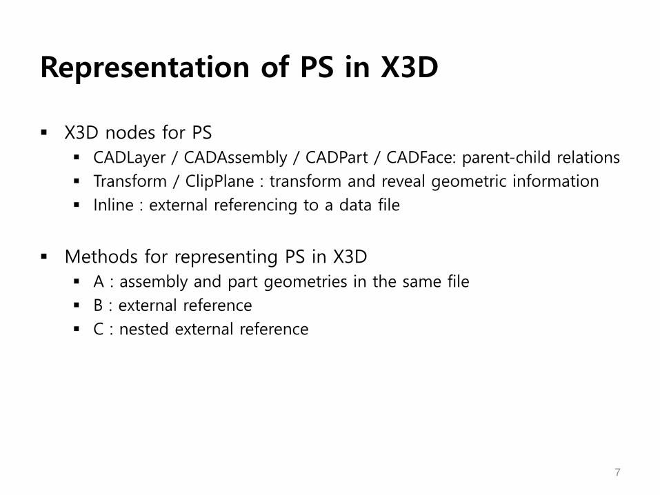
Representation of PS in X3D
X3D nodes for PS CADLayer / CADAssembly / CADPart / CADFace: parent-child relations Transform / ClipPlane : transform and reveal geometric information Inline : external referencing to a data file
Methods for representing PS in X3D A : assembly and part geometries in the same file B : external reference C : nested external reference
7

Hub assembly PS
8
CATIA* Hub Assembly(6 Files)
T(2)
T(3) T(4)
T(5) T(6)
T(1)
H
HHub_Assembly(1)
disc_with_holes(2)
cap(3)
sleeve_sub_assembly(4)
gasket(5)
bushing(6)
* CATIA : Dassault Systemes' CAD/CAM/CAE commercial solution, http://www.3ds.com/products-services/catia/

CatiaHubAssembly.X3D<Transfrom DEF=“T(1)”><CADAssembly name=“Hub_Assembly”>
</CADAssembly></Transform>
<Transform DEF=“T(4)”><CADAssembly name=“sleeve_sub_assembly”>
</CADAssembly></Transform>
<Transform DEF=“T(2)”><CADAssembly name=“disc_with_holes”>
</CADAssembly></Transform>
<CADPart name=“disc_with_holes” ...><CADFace> ... </CADFace>
</CADPart>
<Transform DEF=“T(3)”><CADAssembly name=“cap”>
</CADAssembly></Transform>
<CADPart name=“cap” ...><CADFace> ... </CADFace>
</CADPart>
<Transform DEF=“T(5)”><CADAssembly name=“gasket”>
</CADAssembly></Transform>
<CADPart name=“gasket” ...><CADFace> ... </CADFace>
</CADPart>
<Transform DEF=“T(6)”><CADAssembly name=“bushing”>
</CADAssembly></Transform>
<CADPart name=“bushing” ...><CADFace> ... </CADFace>
</CADPart>
T(2)
T(3) T(4)
T(5) T(6)
T(1)
9
A : assembly and part geometriesin the same file
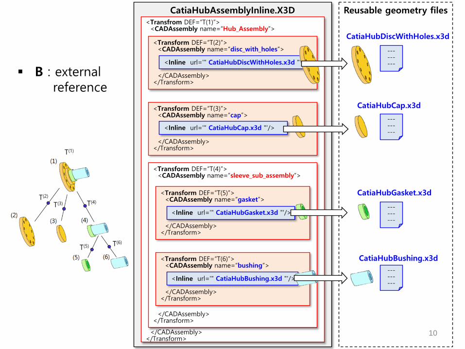
10
CatiaHubAssemblyInline.X3D<Transfrom DEF=“T(1)”><CADAssembly name=“Hub_Assembly”>
</CADAssembly></Transform>
<Transform DEF=“T(4)”><CADAssembly name=“sleeve_sub_assembly”>
</CADAssembly></Transform>
<Transform DEF=“T(2)”><CADAssembly name=“disc_with_holes”>
</CADAssembly></Transform>
<Inline url='" CatiaHubDiscWithHoles.x3d "'/>
<Transform DEF=“T(3)”><CADAssembly name=“cap”>
</CADAssembly></Transform>
<Inline url='" CatiaHubCap.x3d "'/>
<Transform DEF=“T(5)”><CADAssembly name=“gasket”>
</CADAssembly></Transform>
<Inline url='" CatiaHubGasket.x3d "'/>
<Transform DEF=“T(6)”><CADAssembly name=“bushing”>
</CADAssembly></Transform>
<Inline url='" CatiaHubBushing.x3d "'/>
Reusable geometry files
---------
---------
---------
---------
CatiaHubDiscWithHoles.x3d
CatiaHubCap.x3d
CatiaHubGasket.x3d
CatiaHubBushing.x3d
T(2)
T(3) T(4)
T(5) T(6)
T(1)
B : externalreference
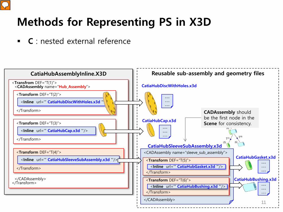
C : nested external reference
Methods for Representing PS in X3D
CatiaHubAssemblyInline.X3D
<Transfrom DEF=“T(1)”><CADAssembly name=“Hub_Assembly”>
</CADAssembly></Transform>
<Transform DEF=“T(4)”>
</Transform>
<Transform DEF=“T(2)”>
</Transform>
<Inline url='" CatiaHubDiscWithHoles.x3d "'/>
<Transform DEF=“T(3)”>
</Transform>
<Inline url='" CatiaHubCap.x3d "'/>
<Inline url='" CatiaHubSleeveSubAssembly.x3d "'/>
Reusable sub-assembly and geometry files
---------
---------
CatiaHubDiscWithHoles.x3d
CatiaHubCap.x3d
<CADAssembly name=“sleeve_sub_assembly”>
</CADAssembly>
<Transform DEF=“T(5)”>
</Transform><Inline url='" CatiaHubGasket.x3d "'/>
<Transform DEF=“T(6)”>
</Transform><Inline url='" CatiaHubBushing.x3d "'/>
CatiaHubSleeveSubAssembly.x3d
CatiaHubGasket.x3d
CatiaHubBushing.x3d
---------
---------
11
CADAssembly should be the first node in the Scene for consistency.

GEOMETRY
12

Representation of Geometry in STEP*
Exact shape representation (STEP AP 214 and 203) Tessellated shape representation Parametric Representation
13* STEP AP242 Project, http://www.ap242.org/geometry-assembly-pmi-interoperability

14
Polygon-based representation [Indexed]Triangle[Fan|Strip]Set IndexedFaceSet [Indexed]QuadSet
Surface-based representation Primitives Extrusion NURBS component
Geometryconversion
Mapping of STEP vocabularies toexisting parametric X3D nodes

PMIPRODUCT MANUFACTURING INFORMATION
15

PMI representation in STEP* and LOTAR**
Product Manufacturing Information Geometry Dimension & Tolerance(GD&T) / annotations / symbols
Graphic representation STEP geometric entities
- polylines (AP 214 / AP 203 Ed2)- tessellated (AP 242)
Semantic representation PMI semantic entities
16* STEP AP242 Project, http://www.ap242.org/geometry-assembly-pmi-interoperability** LOng Term Archiving and Retrieval, http://www.lotar-international.org/
3D annotations3D GD&T
3D symbols
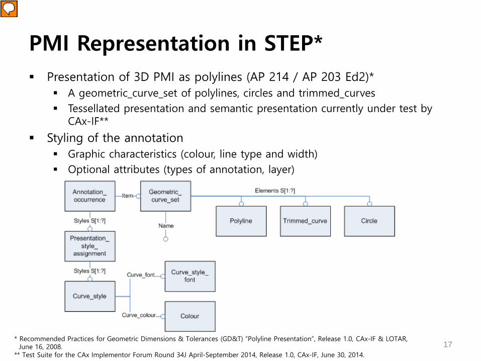
PMI Representation in STEP* Presentation of 3D PMI as polylines (AP 214 / AP 203 Ed2)*
A geometric_curve_set of polylines, circles and trimmed_curves Tessellated presentation and semantic presentation currently under test by
CAx-IF**
Styling of the annotation Graphic characteristics (colour, line type and width) Optional attributes (types of annotation, layer)
17* Recommended Practices for Geometric Dimensions & Tolerances (GD&T) “Polyline Presentation”, Release 1.0, CAx-IF & LOTAR, June 16, 2008.
** Test Suite for the CAx Implementor Forum Round 34J April-September 2014, Release 1.0, CAx-IF, June 30, 2014.

Representing PMI in X3D
A rich set of X3D metadata capabilities exist which might capture all relevant PMI when exporting X3D models
Part 1: Architecture and base components 7 Core component
• MetadataSet, typed Metadata nodes 12 Shape component
• Appearance / FillProperties / LineProperties / Material / TwoSided Material / … 14 Geometry2D component
• Arc2D / Circle2D / Polyline2D / Rectangle2D / … 15 Text component
• FontStyle / Text 35 Layering component
• Layer / LayerSet / … X. Annotation component (extension proposal for X3D version 3.4)
18
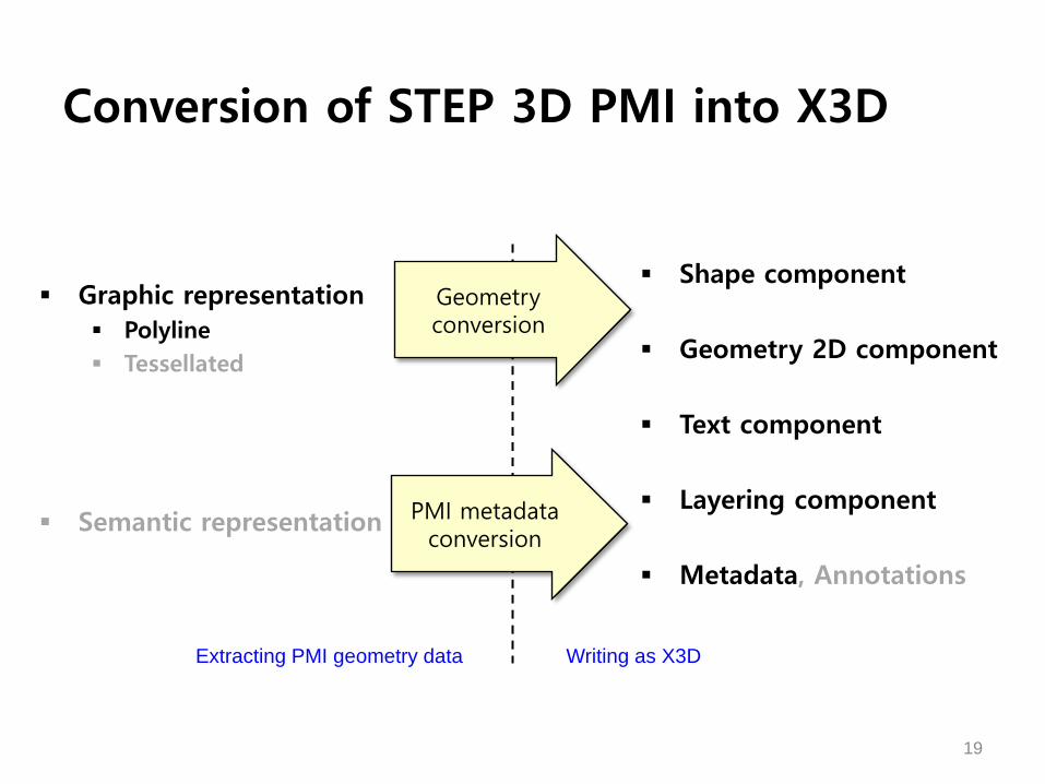
Conversion of STEP 3D PMI into X3D
Graphic representation Polyline Tessellated
Semantic representation
Shape component
Geometry 2D component
Text component
Layering component
Metadata, Annotations
19
Geometryconversion
Extracting PMI geometry data Writing as X3D
PMI metadataconversion