Embed Size (px)
Citation preview

1
Submitted by the expert from the European Commission Informal document GRB-67-04 (67th GRB, 24-26 January 2018, agenda item 17)
Proposal for amendments to UN Regulation No 9 to introduce ASEP requirements for L4 and L5 category vehicles with PMR > 50 W/kg
This informal document was prepared by the expert from the European Commission to complement the document ECE/TRANS/WP.29/2017/2. It proposes the introduction of definitions (paragraph 2), specifications (paragraph 6), transitional provisions (paragraph 11) and of two new Annexes 6 and 7 on technical and administrative requirements.

2
The following two definitions are added to the end of point "2. Definitions":
"2.12. “Power-to-mass ratio index” means the ratio of the rated maximum net power of the vehicle in W to the test mass in kg.
The symbol PMR denotes the power-to-mass ratio index.
2.13. “Idling speed” is the speed of the engine running in warm condition, the gear lever placed in neutral, and the clutch engaged.
The symbol nidle denotes the idling speed expressed in min-1."
The following paragraph is added to the end of point "6. Specifications":
"6.3.4 Additional sound emission provisions
6.3.4.1. The vehicle type to be approved shall meet the requirements of Annex 6 to this Regulation. If the vehicle has user selectable software programs or modes which affect the sound emission of the vehicle, all these modes shall be in compliance with the requirements in Annex 6. Testing shall be based on the worst case scenario.
6.3.4.2. In the application for type approval or for modification or extension of a type approval the manufacturer shall provide a statement in accordance with Annex 7 that the vehicle type to be approved complies with the requirements of paragraphs 6.3.4 of this Regulation.
6.3.4.3 The competent authority may carry out any test prescribed in this Regulation."
The following amendments to point 11 are in accordance with the transitional provisions guidelines in the document ECE/TRANS/WP.29/2017/107, which was adopted by the 173rd session of WP29.
Paragraph 11.3 is replaced by the following paragraph:
"11.3. Contracting Parties applying this UN Regulation shall not refuse to grant UN type-approvals according to any preceding series of amendments to this UN Regulation or extensions thereof."
Paragraph 11.6 is replaced by the following paragraph:
"11.6. Notwithstanding the transitional provisions above, Contracting Parties who start to apply this UN Regulation after the date of entry into force of the most recent series of amendments are not obliged to accept UN type-approvals which were granted in accordance with any of the preceding series of amendments to this UN Regulation."
The following paragraphs are added to the end of point "11. Transitional provisions":
"11.9. As from the official date of entry into force of the XX series of amendments, no Contracting Party applying this UN Regulation shall refuse to grant or refuse to accept UN type-approvals under this UN Regulation as amended by the XX series of amendments.
Comment [v1]: "this Regulation" is the UN Regulation No 9.
Comment [v2]: This proposed series of amendments.
Comment [v3]: This proposed series of amendments.
3
11.10. As from [1 September following the entry into force of the XX series of amendments] [1 September following the entry into force of the XX series of amendments + 12 months ] ("Date (b)"), Contracting Parties applying this UN Regulation shall not be obliged to accept UN type-approvals to the preceding series of amendments, first issued after "Date (b)".
11.11. Until 1 September of [year of "Date (c) = year of "Date (b)" + 36 months] ("Date (c)"), Contracting Parties applying this UN Regulation shall accept UN type-approvals to the preceding series of amendments, first issued before "Date (b)".
11.12. As from 1 September of [year of "Date (c) = year of "Date (b)" + 36 months] ("Date (c)"), Contracting Parties applying this UN Regulation shall not be obliged to accept type-approvals issued to the preceding series of amendments to this Regulation.
11.13. Notwithstanding paragraph 11.12, Contracting Parties applying the UN Regulation shall continue to accept UN type-approvals issued according to the preceding series of amendments to the UN Regulation, for the vehicles/vehicle systems which are not affected by the changes introduced by the XX series of amendments."
Comment [v4]: One of the two to be chosen. The second bracketed text is to be kept if the first one results in < 12 months from "Date (a)" to "Date (b)".
Comment [v5]: Bracketed text to be replaced by the calculated "year of "Date (c)" number.
Comment [v6]: Bracketed text to be replaced by the calculated "year of "Date (c)" number.
Comment [v7]: This proposed series of amendments.
4
The following Annexes are added:
"Annex 6
Additional Sound Emission Provisions (ASEP)
Comment: The following text is in line with the corresponding requirements in UN Regulation No 41-04 and modified in order to meet the requirements of Annex 3 of this Regulation, as well as to make the ASEP requirements more robust.
1. Scope
1.1. This Annex applies to vehicles of category L4 and L5 with PMR >50.
Comment: PMR was added in paragraph 2, definitions. For Hybrids the system power would be required in order to calculate PMR.
1.2. Vehicles with variable gear ratios or automatic transmission with non-lockable gear ratios are exempted from the requirements of this Annex, if the vehicle manufacturer provides technical documents to the type approval authority showing, that the vehicle's engine speed at BB' does neither exceed nBB' + 0.05 * (nrated – nidle) nor fall below nBB' – 0.05 * (nrated – nidle) for any test condition inside the ASEP control range defined in paragraph 2.5. below, where nBB' is the average engine speed at BB' from the two valid acceleration tests according to paragraphs 2. and 3. of Annex 3.
nidle shall be measured by the Technical Service in accordance with the requirements laid down in Annex 2 of GTR 15 (ECE/TRANS/180/Add.15/Amend.1) during the ASEP test, performed in accordance with paragraph 2 of this Annex, unless the manufacturer presents a test report or a Communication which mentions the value of nidle , measured in accordance with the above mentioned requirements of GTR 15.
2. Additional sound emission requirements
2.1. Measuring instruments
The requirements for the measurement equipment are identical to those defined in paragraph 1.1. of Annex 3 for the tests of the vehicle in motion.
2.2. Acoustical environment, meteorological conditions and background noise
The requirements concerning the acoustical environment, the meteorological conditions and the background noise are identical to those defined in paragraph 2.1. of Annex 3 for the tests of the vehicle in motion.
2.3. Microphone positions and conditions of the vehicle
The requirements concerning the conditions of the vehicle and the microphone positions are identical to those defined in paragraphs 2.2 and 3.1, respectively, of Annex 3 for the tests of the vehicle in motion.
2.4. General operating conditions
The path of the centreline of the vehicle shall follow the line CC' as closely as possible throughout the entire test, from the approach to line AA' until the rear of the vehicle passes line BB' (see Annex 5 – Figure 1).
Comment [v8]: Paragraph 2 is on the conditions of measurement.
Comment [v9]: Paragraph 3 is on the methods of sound emission levels measurement.
5
In addition, the conditions of paragraph 3.1.2.1 of Annex 3 shall apply.
2.5. ASEP control range
The requirements of this Annex apply to any vehicle operation with the following restrictions:
(a) vAA' shall be at least 20 km/h
(b) vBB' shall not exceed 80 km/h
(c) nAA' shall be at least 0.1 * (nrated – nidle) + nidle,
(d) nBB' shall not exceed nBB’_max,
nBB’_max shall be determined by
(a) 0.85 * (nrated – nidle) + nidle for PMR < 66 and
3.4 * PMR-0.33 * (nrated – nidle) + nidle for PMR > 66,
or
(b) 1.3* nBB’_ref,
whichever is higher, but shall not exceed nrated.
nBB’_ref is calculated in accordance to paragraph 3.3.1 of this Annex.
Comment: Depending on the design of the vehicle it could happen, that nBB’_ref is rather close to nBB’_max, but both are far below nrated. In this case the sound emission for more aggressive driving behaviour would not be controlled by ASEP. Therefore, it is required that the control range for the engine speed nBB’ should cover engine speeds up to 130% of nBB’_ref, without exceeding nrated.
3. Testing compliance by measurements
3.1. General
The Type Approval Authority as well as the Technical Service may request tests to check the compliance of the vehicle with the requirements of paragraph 2 above. To avoid undue work load testing is restricted to the reference points defined in paragraph 3.2. below and up to two additional operating conditions other than the reference points but inside the ASEP control range.
3.2 Test procedure
The same test procedure as described in paragraph 3.1.2.1 of Annex 3 shall be applied.
3.3. ASEP test conditions
3.3.1 ASEP reference test
3.3.1.1. Test speed and gear selection
The vehicle shall be tested at the operating conditions as described in paragraph 3.1.2.2 of Annex 3.
3.3.1.2. The sound level determination shall be performed as described in paragraph 3.1.3 of Annex 3. At least two measurements shall be made on each side of the vehicle.
Comment [v10]: Paragraph 3.1.2.1 is on the acceleration test execution.
Comment [v11]: Paragraph 3.1.2.1 is on the acceleration test execution.
Comment [v12]: Paragraph 3.1.2.2 is on the determination of the approach vehicle speed and the gear use.
Comment [v13]: Paragraph 3.1.3 is on the sound level determination.
6
The final sound level result shall be calculated according to paragraph 3.1.4. of Annex 3.
This value constitutes the reference level Lref. The gear chosen for the test constitutes the reference gear gref.
3.3.1.3 The nBB’ values of the measurements shall be averaged and rounded to the nearest integer.
This value constitutes the reference engine speed nBB’_ref.
Comment: The ASEP reference test is a copy of the Annex 3 test and its results provide the data for the reference point. The reference point is determined by the sound level Lref, the chosen gear gref and the engine speed vBB’ at the end of the test track BB’. In UN Regulation 41-04 the target speed and the reference engine speed is vPP’ and nPP’. Since these values are not required in this Regulation, the reference was moved to BB’. Measurements should be performed in order to check the validity of this modification.
Comment: The approach for the two ASEP tests, described in the following paragraphs, is as follows: The engine speed nBB’ for the first test shall be sufficiently below and the engine speed for the second test shall be sufficiently above nBB’_ref in order to cover the operation conditions in practical vehicle use as much as possible.
3.3.2 ASEP test 1
3.3.2.1 Test speed and gear selection
The selected gear shall be
(a) gref or gref + 1, if gref = 2,
(b) gref. – 1, gref or gref + 1, if gref > 2
The gear and vAA’ shall be chosen in that way, so that the test condition complies with the control range specifications and that
nBB’ < 0,85*nBB’_ref
Pretests may be carried out in order to determine an appropriate measurement condition.
3.3.2.2 The sound level determination shall be performed as described in paragraph 3.1.3 of Annex 3. At least two measurements shall be made on each side of the vehicle.
The final sound level result shall be calculated according to paragraph 3.1.4. of Annex 3.
3.3.2.3 Data processing and reporting
The engine speed measurements at AA' and BB' shall be averaged arithmetically. The results in units of min-1 shall be mathematically rounded to the nearest integer. The nBB’ value shall be used for the calculations specified in paragraph 4 of this Annex.
The final sound pressure level for the full throttle acceleration shall not exceed the limits specified in paragraph 4 of this Annex.
3.3.3 ASEP test 2
3.3.3.1 Test speed and gear selection
The selected gear shall be
Comment [v14]: Paragraph 3.1.4 is on the calculation of the final test result.
Comment [v15]: Paragraph 3.1.3 is on the sound level determination.
Comment [v16]: Paragraph 3.1.4 is on the calculation of the final test result.
7
(a) gref or gref + 1, if gref = 2,
(b) gref. – 1, gref or gref + 1, if gref > 2
The gear and vAA’ shall be chosen in that way, so as the test condition complies with the control range specifications and that
nBB’ > 1,15*nBB’_ref
Pretests may be carried out in order to determine an appropriate measurement condition.
3.3.3.2 The sound level determination shall be performed as described in paragraph 3.1.3 of Annex 3. At least two measurements shall be made on each side of the vehicle.
The final sound level result shall be calculated according to paragraph 3.1.4. of Annex 3.
3.3.3.3 Data processing and reporting
The engine speed measurements at AA' and BB' shall be averaged arithmetically. The results in units of min-1 shall be mathematically rounded to the nearest integer. The nBB’ value shall be used for the calculations specified in paragraph 4 of this Annex.
The final sound pressure level for the full throttle acceleration shall not exceed the limits specified in paragraph 4 of this Annex.
4. ASEP limits1
The maximum noise level recorded during the passage of the vehicle through the test track shall not exceed:
Lref + (1 * (nBB' – nBB’_ref) / 1,000) + [3] for nBB' < nBB’_ref and
Lref + (5 * (nBB' – nBB’_ref) / 1,000) + [3] for nBB' ≥ nBB’_ref
with Lref and nBB’_ref as specified in paragraph 3.3.1 and nBB’ as specified in paragraphs 3.3.2 and 3.3.3.
Comment: The ASEP requirements, proposed in this document, should be checked/assessed by measurements performed for vehicles of current or future technologies.
Comment [v17]: To simplify: 3.3.2.2 and 3.3.3.2 being identical, as well as 3.3.2.3 and 3.3.3.3 being identical, may be drafted only once as 3.3.4.
Comment [v18]: To be decided
Comment [v19]: To be decided
8
Annex 7
Statement of compliance with the Additional Sound Emission Provisions (ASEP)
Comment: This Annex is in line with UN Regulation 41-04 and amended in order to comply with this Regulation. Ideally, this Annex should be integrated in Annex 1 (Communication).
(Maximum format: A4 (210 x 297 mm))
...................... (Name of manufacturer) attests that vehicles of this type ..................... (type with regard to its noise emission pursuant to Regulation No. 9) comply with the requirements of paragraph 6.3.4. of Regulation No. 9.
...................... (Name of manufacturer) makes this statement in good faith, after having performed an appropriate evaluation of the sound emission performance of the vehicles.
Date: ..............................................................................................................................................
Name of authorized representative: .............................................................................................
Signature of authorized representative: .......................................................................................
"

9
Justification ASEP for high powered L4 and L5 vehicles, used for passenger transport, is proposed in line with the ASEP in UN Regulation No 41.04, due to comparable sound emissions levels of L4 and L5 vehicles with the ones of L3 vehicles and the possibility of applying similar measurement methods for sound emissions for those vehicle categories. This is also supported by the Commission study on enhanced sound requirements for mopeds, quads and replacement silencers of L-category vehicles, which led to appropriate amendments to UN Regulation Nos 9, 63 and 92.
The appropriate transitional provisions are also added, in accordance with the provisions of the document ECE/TRANS/WP.29/2017/107.
10
For reference purposes only in this document
Annex 5
Specifications for the test site1
1. Introduction
This annex describes the specifications relating to the physical characteristics and the laying of the test track. These specifications based on a special standard2 describe the required physical characteristics as well as the test methods for these characteristics.
2. Required characteristics of the surface
A surface is considered to conform to this standard provided that the texture and voids content or sound absorption coefficient have been measured and found to fulfil all the requirements of paragraphs 2.1. to 2.4. below and provided that the design requirements (paragraph 3.2. below) have been met.
2.1. Residual voids content
The residual voids content, VC, of the test track paving mixture shall not exceed 8 per cent. For the measurement procedure, see paragraph 4.1. below.
2.2. Sound absorption coefficient
If the surface fails to conform to the residual voids content requirement, the surface is acceptable only if its sound absorption coefficient, α ≤ 0.10. For the measurement procedure, see paragraph 4.2. below. The requirements of paragraphs 2.1. above and this paragraph are met also if only sound absorption has been measured and found to be α ≤ 0.10.
Note: The most relevant characteristic is the sound absorption, although the residual voids content is more familiar among road constructors. However, sound absorption needs to be measured only if the surface fails to comply with the voids requirement. This is because the latter is connected with relatively large uncertainties in terms of both measurements and relevance and some surfaces therefore may be rejected erroneously on the basis of the voids measurement only.
2.3. Texture depth
The texture depth (TD) measured according to the volumetric method (see paragraph 4.3. below) shall be:
TD ≥ 0.4 mm
2.4. Homogeneity of the surface
Every practical effort shall be made to ensure that the surface is made to be as homogeneous as possible within the test area. This includes the texture and
1 The specifications for the test site reproduced in this annex are valid until the end of the period
indicated in paragraph 11.8. of this Regulation. 2 ISO 10844:1994

11
voids content, but it should also be observed that if the rolling process results in more effective rolling at some places than at others, the texture may be different and unevenness causing bumps may also occur.
2.5. Period of testing
In order to check whether the surface continues to conform to the texture and voids content or sound absorption requirements stipulated in this standard, periodic testing of the surface shall be done at the following intervals:
(a) For residual voids content or sound absorption:
When the surface is new; if the surface meets the requirements when new, no further periodical testing is required.
(b) For texture depth (TD):
When the surface is new; when the sound testing starts (Note: Not before four weeks after laying); then every 12 months.
3. Test surface design
3.1. Area
When designing the test track lay-out it is important to ensure that, as a minimum requirement, the area traversed by the vehicles running through the test strip is covered with the specified test material with suitable margins for safe and practical driving. This will require the width of the track to be at least 3 m and the length of the track to extend beyond lines AA and BB by at least 10 m at either end. Figure 1 shows a plan of a suitable test site and indicates the minimum area which shall be machine laid and machine compacted with the specified test surface material. According to Annex 3, paragraph 3.1.1.1., measurements have to be made on each side of the vehicle. This can be done either by measuring with two microphone locations (one on each side of the track) and driving in one direction, or measuring with a microphone only on one side of the track but driving the vehicle in two directions. If the latter method is used, then there are no surface requirements on that side of the track where there is no microphone.

12
Figure 1 Minimum requirement for test surface area. The shaded part is called "Test Area"
3.2. Design and preparation of the surface
3.2.1. Basic design requirements; the test surface shall meet four design requirements:
3.2.1.1. It shall be a dense asphaltic concrete;
3.2.1.2. The maximum chipping size shall be 8 mm (tolerances allow from 6.3 to 10 mm);
3.2.1.3. The thickness of the wearing course shall be ≥ 30 mm;
3.2.1.4. The binder shall be a straight penetration grade bitumen without modification.
3.2.2. Design guidelines
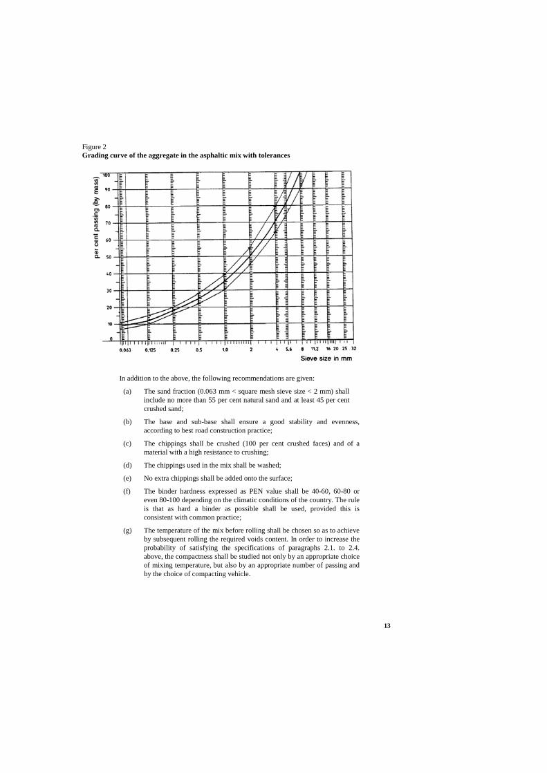
As a guide to the surface constructor, an aggregate grading curve which will give desired characteristics is shown in Figure 2. In addition, Table 1 gives some guidelines for obtaining the desired texture and durability. The grading curve fits the following formula:
P (% passing) = 100 . (d/dmax)1/2
where: d = square mesh sieve size, in mm dmax = 8 mm for the mean curve dmax = 10 mm for the lower tolerance curve dmax = 6.3 mm for the upper tolerance curve
13
Figure 2 Grading curve of the aggregate in the asphaltic mix with tolerances
In addition to the above, the following recommendations are given:
(a) The sand fraction (0.063 mm < square mesh sieve size < 2 mm) shall include no more than 55 per cent natural sand and at least 45 per cent crushed sand;
(b) The base and sub-base shall ensure a good stability and evenness, according to best road construction practice;
(c) The chippings shall be crushed (100 per cent crushed faces) and of a material with a high resistance to crushing;
(d) The chippings used in the mix shall be washed;
(e) No extra chippings shall be added onto the surface;
(f) The binder hardness expressed as PEN value shall be 40-60, 60-80 or even 80-100 depending on the climatic conditions of the country. The rule is that as hard a binder as possible shall be used, provided this is consistent with common practice;
(g) The temperature of the mix before rolling shall be chosen so as to achieve by subsequent rolling the required voids content. In order to increase the probability of satisfying the specifications of paragraphs 2.1. to 2.4. above, the compactness shall be studied not only by an appropriate choice of mixing temperature, but also by an appropriate number of passing and by the choice of compacting vehicle.

14
Table 1 Design guidelines
Target values
Tolerances
By total mass
of mix
By mass of the
aggregate
Mass of stones, square mesh sieve (SM) > 2 mm 47.6 % 50.5 % ±5
Mass of sand 0.063 < SM < 2 mm 38.0 % 40.2 % ±5
Mass of filler SM < 0.063 mm 8.8 % 9.3 % ±2
Mass of binder (bitumen) 5.8 % N.A. ±0.5
Max. chipping size 8 mm 6.3 - 10
Binder hardness (see paragraph 3.2.2.(f))
Polished stone value (PSV) > 50
Compactness, relative to Marshall compactness 98 %
4. Test method
4.1. Measurement of the residual voids content
For the purpose of this measurement, cores have to be taken from the track in at least four different positions which are equally distributed in the test area between lines AA and BB (see Figure 1). In order to avoid in homogeneity and unevenness in the wheel tracks, cores should not be taken in wheel tracks themselves, but close to them. Two cores (minimum) should be taken close to the wheel tracks and one core (minimum) should be taken approximately midway between the wheel tracks and each microphone location.
If there is a suspicion that the condition of homogeneity is not met (see paragraph 2.4. above), cores shall be taken from more locations within the test area. The residual voids content has to be determined for each core, then the average value from all cores shall be calculated and compared with the requirement of paragraph 2.1. above. In addition, no single core shall have a voids value which is higher than 10 per cent. The test surface constructor is reminded of the problem which may arise when the test area is heated by pipes or electrical wires and cores shall be taken from this area. Such installations shall be carefully planned with respect to future core drilling locations. It is recommended that a few locations of size approximately 200 x 300 mm should be left where there are no wires/pipes or where the latter are located deep enough in order not to be damaged by cores taken from the surface layer.
4.2. Sound absorption coefficient
The sound absorption coefficient (normal incidence) shall be measured by the impedance tube method using the procedure specified in ISO/DIS 10 534: "Acoustics - Determination of sound absorption coefficient and impedance by a tube method".
Regarding test specimens, the same requirements shall be followed as regarding the residual voids content (see paragraph 4.1 above).
The sound absorption shall be measured in the range between 400 Hz and 800 Hz and in the range between 800 Hz and 1,600 Hz (at least at the centre
15
frequencies of third octave bands) and the maximum values shall be identified for both of these frequency ranges.
Then these values, for all test cores shall be averaged to constitute the final result.
4.3. Volumetric macrotexture measurement
For the purpose of this standard, texture depth measurements shall be made on at least 10 positions evenly spaced along the wheel tracks of the test strip and the average value taken to compare with the specified minimum texture depth. For the description of the procedure see standard ISO 10844:1994.
5. Stability in time and maintenance
5.1. Age influence
In common with any other surfaces, it is expected that the tyre/road sound level measured on the test surface may increase slightly during the first 6-12 months after construction.
The surface will achieve its required characteristics not earlier than four weeks after construction.
The stability over time is determined mainly by the polishing and compaction by vehicles driving on the surface. It shall be periodically checked as stated in paragraph 2.5. above.
5.2. Maintenance of the surface
Loose debris or dust which could significantly reduce the effective texture depth shall be removed from the surface. In countries with winter climates, salt is sometimes used for de-icing. Salt may alter the surface temporarily or even permanently in such a way as to increase sound, and is therefore not recommended.
5.3. Repaving the test area
If it is necessary to repave the test track, it is usually unnecessary to repave more than the test strip (of 3 m width in Figure 1) where vehicles are driving, provided the test area outside the strip met the requirement of residual voids content or sound absorption when it was measured.
6. Documentation of the test surface and of tests performed on it
6.1. Documentation of the test surface
The following data shall be given in a document describing the test surface:
6.1.1. The location of the test track.
6.1.2. Type of binder, binder hardness, type of aggregate, maximum theoretical density of the concrete (DR), thickness of the wearing course and grading curve determined from cores from the test track.
6.1.3. Method of compaction (e.g. type of roller, roller mass, number of passes).
6.1.4. Temperature of the mix, temperature of the ambient air and wind speed during laying of the surface.
6.1.5. Date when the surface was laid and name of the contractor.
16
6.1.6. All test results or at least the latest test result, including:
6.1.6.1. The residual voids content of each core;
6.1.6.2. The locations in the test area from where the cores for voids measurements have been taken;
6.1.6.3. The sound absorption coefficient of each core (if measured). Specify the results both for each core and each frequency range, as well as the overall average;
6.1.6.4. The locations in the test area from where the cores for absorption measurement have been taken;
6.1.6.5. Texture depth, including the number of tests and standard deviation;
6.1.6.6. The institution responsible for the tests according to paragraphs 6.1.6.1. and 6.1.6.2. above and the type of equipment used;
6.1.6.7. Date of the test(s) and date when the cores were taken from the test track.
6.2. Documentation of vehicle sound tests conducted on the surface
In the document describing the vehicle sound test(s) it should be stated whether all the requirements of this standard were fulfilled or not. Reference shall be given to a document according to paragraph 6.1. above describing the results which verify this."