Embed Size (px)
Citation preview

2
Parameter Guide
E
Parameter GuideParameter Guide

i
Table of Contents
How to use this Parameter Guide ................................................... 1
1. PERFORMANCE mode ............................................................... 2
2. PERFORMANCE EDITOR DEFINE mode........................................ 4PED-1 [PE1 Definition] ...................................................................................................... 4PED-2 [PE2 Definition]...PED-4 [PE4 Definition] .......................................................... 5PED-5 [Initialize] ................................................................................................................ 5PED-6 [Copy] ...................................................................................................................... 5
3. ARPEGGIATOR PATTERN DEFINE mode ...................................... 7Arpeggio-1 [Arpeggio Param] ......................................................................................... 7Arpeggio-2 [Velocity Param] ........................................................................................... 8Arpeggio-3 [Gate Param] .................................................................................................. 8Arpeggio-4 [Pattern Copy] ............................................................................................... 9Pattern-4 [User Pat Param] ............................................................................................... 9Pattern-5 [Step] ................................................................................................................. 10Pattern-6 [Pattern Copy] ................................................................................................. 11
4. EDIT mode .............................................................................. 12
4-1. OSC Section .................................................................................. 12OSC-cmn1 [Oscillator Set] .............................................................................................. 12OSC-cmn2 [Pitch EG Level] Pitch EG .......................................................................... 13OSC-cmn3 [Pitch EG Time] Pitch EG ........................................................................... 14OSC-cmn4 [Pitch EG Ctrl] Pitch EG Keyboard Traking/Velocity Control ............. 15OSC-cmn5 [Pitch Bend] Pitch Bender/After Touch Bending ................................... 16OSC-cmn6 [Portamento] ................................................................................................. 17OSC-cmn7 OSC Menu ..................................................................................................... 18Osillator 1, Osillator 2 ...................................................................................................... 19OSC1-1 [Basic Pitch] ........................................................................................................ 19OSC1-2 [Pitch Modulation] ............................................................................................ 20OSC1-3 [Pitch Slope] ........................................................................................................ 21OSC1-4 [Pitch Mod LFO] - Pitch Modulation LFO ..................................................... 22OSC2-1 [Basic Pitch] ...OSC2-4 [Pitch Mod LFO] ........................................................ 22Standard Oscillator .......................................................................................................... 23OSC1-5 [STD WaveLevel] - OSC Setting ...................................................................... 24OSC1-6 [STD Wave Form] - Wave Form Modulation ................................................ 25COMB Filter Oscillator .................................................................................................... 26OSC1-5 [COMB Input] .................................................................................................... 27OSC1-6 [COMB Feedback] ............................................................................................. 28OSC1-7 [COMB Loop LPF Frequency] ......................................................................... 29VPM Oscillator ................................................................................................................. 30OSC1-5 [VPM Carrier Wave] ......................................................................................... 30OSC1-6 [VPM Carrier] ..................................................................................................... 31OSC1-7 [VPM Cari Shape] .............................................................................................. 32OSC1-8 [VPM Feedback Gain] ....................................................................................... 33OSC1-9 [VPM Modulator Pitch] .................................................................................... 33OSC1-10 [VPM Modulator] ............................................................................................ 34

ii
OSC1-11 [VPM Modulator Level] .................................................................................. 35Cross/Sync/Ring Modulation Oscillator ..................................................................... 36OSC2-5 [MOD OSC Type] .............................................................................................. 38OSC2-6 [Modulator Cross Modulation] ....................................................................... 39Brass Model Oscillator .................................................................................................... 40OSC1-5 [Brass Type] ........................................................................................................ 41OSC1-6 [Brass Pressure EG] ........................................................................................... 42OSC1-7 [Brass Pressure Mod] ........................................................................................ 43OSC1-8 [Brass Lip] ........................................................................................................... 44OSC1-9 [Brass Bell] .......................................................................................................... 45Reed Model Oscillator ..................................................................................................... 46OSC1-5 [Reed Type] ........................................................................................................ 46OSC1-6 [Reed Pressure EG] ............................................................................................ 47OSC1-7 [Reed PressureMod] - Reed Pressure Modulation ....................................... 48OSC1-8 [Reed Reed Mod] ............................................................................................... 49Pluck Oscillator ................................................................................................................ 50OSC1-5 [Pluck Attack] ..................................................................................................... 50OSC1-6 [Pluck Noise Filter] ............................................................................................ 51OSC1-7 [Pluck Attack Curve] ......................................................................................... 52OSC1-8 [Pluck String Position] ...................................................................................... 53OSC1-9 [Pluck String Loss] ............................................................................................. 54OSC1-10 [Pluck Inharmonicity] ..................................................................................... 55OSC1-11 [Pluck Decay & Release] ................................................................................. 56SUB Oscillator ................................................................................................................... 57SUB OSC-1 [Sub OSC] ..................................................................................................... 57Noise Generator ............................................................................................................... 58NOISE-1 [Noise Genrator] .............................................................................................. 58[UTY] - Utility ................................................................................................................ 59OSCU-1 [Initialize] ........................................................................................................... 59OSCU-2 [Set Initialize] .................................................................................................... 59OSCU-3 [COPY] ............................................................................................................... 60OSCU-4 [Duplicate] ......................................................................................................... 60OSCU-5 [Swap] ................................................................................................................ 61
4-2. Wave Shape Section ..................................................................... 62WS-1 [WaveShap Menu] ................................................................................................. 62[ WS1 ] ................................................................................................................................ 63WS1-1 [Input Gain] .......................................................................................................... 63WS1-2 [Input Offset] ........................................................................................................ 64WS1-3 [Feedback & Cross Loop] ................................................................................... 65WS1-4 [Wave Shape] ....................................................................................................... 65WS1-5 [Output] ................................................................................................................ 67[ WS2 ] ................................................................................................................................ 67WS2-1 [Input Gain]...WS2-5 [Output] ........................................................................... 67[UTY] - Utility ................................................................................................................ 68WSU-1 [Initialize] ............................................................................................................. 68WSU-2 [Copy] ................................................................................................................... 68WSU-3 [Swap] .................................................................................................................. 69
4-3. Mixer Section................................................................................ 70MIX-1 [OSC1 fi OUT1] .................................................................................................... 70MIX-2 [OSC1 fi OUT2] .................................................................................................... 71MIX-3 [OSC2 fi OUT1] .................................................................................................... 71
iii
MIX-4 [OSC2 fi OUT2] .................................................................................................... 71MIX-5 [SUBOSC fi OUT1] ............................................................................................... 71MIX-6 [SUBOSC fi OUT2] ............................................................................................... 71MIX-7 [NOISE fi OUT1] .................................................................................................. 72MIX-8 [NOISE fi OUT2] .................................................................................................. 72MIX-9 [Feedback fi OUT1] .............................................................................................. 72MIX-10 [Feedback fi OUT2] ............................................................................................ 72
4-4. Filter Section ................................................................................. 73FLT-1 [Filter Menu].......................................................................................................... 73FL1-1 [Type & Input] ....................................................................................................... 74FL1-2 [Cutoff] ................................................................................................................... 75FL1-3 [Resonance] ............................................................................................................ 76FL1-4 [Fc Kbd Trk] Cutoff Frequency Keyboard Track ............................................ 77FL1-5 [Fc Modulation] ..................................................................................................... 78FL2-1 [Type & Input]...FL2-5 [Fc Modulation] ............................................................ 78[UTY] - Utility ................................................................................................................ 79FLU-1 [Initialize] .............................................................................................................. 79FLU-2 [Copy] .................................................................................................................... 80FLU-3 [Swap] .................................................................................................................... 80
4-5. Amplifier Section........................................................................... 81AMP-1 [Amp Menu] ........................................................................................................ 81[AMP1] .............................................................................................................................. 82AMP1-1 [Amplitude] - Amplitude 1 ............................................................................. 82AMP1-2 [Amp Modulation] ........................................................................................... 83[AMP2] .............................................................................................................................. 83AMP2-1 [Amplitude]...AMP2-2 [Amp Modulation] .................................................. 83[AMP EG] .......................................................................................................................... 84AEG-1 [Amp EG Level] ................................................................................................... 84AEG-2 [Amp EG Time] ................................................................................................... 85AEG-3 [Amp EG KbdTrk] Amplitude EG Keyboard Tracking .............................. 86AEG-4 [Amp EG Velocity] Amplitude EG Velocity Control .................................... 87[UTY] - Utility ................................................................................................................ 88AMPU-1 [Amp Copy] ..................................................................................................... 88AMPU-2 [Amp Swap] ..................................................................................................... 88AMPU-3 [AmpEG Initialize] .......................................................................................... 89AMPU-4 [AmpEG Copy] ................................................................................................ 89
4-6. Effect Section ................................................................................ 90FX-1 [Distortion & Wah] ................................................................................................. 90[DIST] - Distortion ........................................................................................................... 91DIST-1 [Distortion] - Distortion ..................................................................................... 91DIST-2 [Fx Balance] - Distortion .................................................................................... 92[ WAH ] - Wah .................................................................................................................. 93WAH-1 [Level & Resonance] - Wah .............................................................................. 93WAH-2 [Sweep] - Wah .................................................................................................... 94WAH-3 [Fx Balance] - Wah ............................................................................................ 95[UTY] - Utility ................................................................................................................... 95DWU-1 [Initialize] ............................................................................................................ 95DWU-2 [Copy] .................................................................................................................. 96FX-2 [Delay/Reverb] ....................................................................................................... 97[DELAY] - Delay .............................................................................................................. 98
iv
DLY-1 [Delay & Fback] - Delay ...................................................................................... 98DLY-2 [Fx Balance] - Delay ............................................................................................. 99[CH/FL] - Chorus/Flanger .......................................................................................... 100CHFL-1 [Delay & F.Back] - Chorus/Flanger ............................................................. 100CHFL-2 [Modulation] - Chorus/Flanger ................................................................... 100CHFL-3 [Fx Balance] - Chorus/Flanger ..................................................................... 101[UTY] - Utility ................................................................................................................. 102CDU-1 [Initialize] ........................................................................................................... 102CDU-2 [Copy] ................................................................................................................. 103[REVERB] - Reverb ........................................................................................................ 104REV-1 [Reverb Time] - Reverb ..................................................................................... 104REV-2 [Fx Balance] - Reverb ......................................................................................... 105[UTY] - Utility ................................................................................................................. 107REVU-1 [Initial] .............................................................................................................. 107REVU-2 [Copy] ............................................................................................................... 107FX-3 [Dual Peaking EQ] - 2 Band PEQ ....................................................................... 108[PEQ] - 2 Band Parametric EQ ..................................................................................... 108PEQ-1 [High EQ] - 2 Band PEQ ................................................................................... 108PEQ-2 [Low EQ] - 2 Band PEQ .................................................................................... 109[UTY] - Utility ................................................................................................................. 110EQU-1 [Initialize] ........................................................................................................... 110EQU-2 [Copy] - 2 Band PEQ Utility ............................................................................ 110
4-7. EG (Envelope Generator) Section.................................................. 111EG-1 [EG Menu] ............................................................................................................. 111[EG1] ................................................................................................................................ 112EG1-1 [EG Level] ............................................................................................................ 112EG1-2 [EG Time] ............................................................................................................ 113EG1-3 [Time KBD TRK] EG Time Keyboard Tracking ............................................ 114EG1-4 [Velocity Control] ............................................................................................... 115[EG2] EG2-1...4 ............................................................................................................... 116[EG3] EG3-1...4 ............................................................................................................... 116[EG4] EG4-1...4 ............................................................................................................... 116[UTY] - Utility ................................................................................................................. 116EGU-1 Initialize .............................................................................................................. 116EGU-2 Copy .................................................................................................................... 117EGU-3 Swap .................................................................................................................... 117
4-8. LFO Section................................................................................. 118LFO-1 [LFO Menu] ........................................................................................................ 118[LFO1] .............................................................................................................................. 119LFO1-1 [Wave & Mode] ................................................................................................ 119LFO1-2 [Frequency] ....................................................................................................... 121LFO1-3 [Modulation Source] ........................................................................................ 121LFO1-4 [Amplitude] ...................................................................................................... 122[LFO2] LFO2-1...4 ........................................................................................................... 123[LFO3] LFO3-1...4 ........................................................................................................... 123[LFO4] LFO4-1...4 ........................................................................................................... 123[UTY] - Utility ................................................................................................................. 123LFOU-1 [Copy] ............................................................................................................... 123LFOU-2 [Swap] ............................................................................................................... 124
4-9. Common Section ......................................................................... 125

v
CMN-1 [Program Name] .............................................................................................. 125CMN-2 [Prog Category]-Program Category .............................................................. 126CMN-3 [Voice Control] ................................................................................................. 127CMN-4 [Scale] ................................................................................................................. 128CMN-5 [Wheel1/2 Assign] ........................................................................................... 129CMN-6 [Wheel3 Assign] - Wheel Controller3 Assign .............................................. 129CMN-7 [Ribbon Assign] ............................................................................................... 130CMN-8 [Pedal & SW Assign] ....................................................................................... 131CMN-9 [Copy Control] ................................................................................................. 132CMN-10 [Initialize Program] ....................................................................................... 132
4-10. Global Section .......................................................................... 133GLB-1 [Tune & Transpose] ........................................................................................... 133GLB-2 [Curve & Effects] ................................................................................................ 134GLB-3 [User Scale] ......................................................................................................... 135GLB-4 [Sens&Polar]-Sensitivity & Polarity ................................................................ 136GLB-5 [Knob Controller Assign] ................................................................................. 137GLB-6 [Arpeggio Controller] ....................................................................................... 137GLB-7 [EC5 Function] ................................................................................................... 138GLB-8 [MIDI] .................................................................................................................. 139GLB-9 [MIDI Pitch Bend] .............................................................................................. 139GLB-10 [MIDI After Touch] .......................................................................................... 141GLB-11 [MIDI Control Change] ................................................................................... 142GLB-12 [MIDI Program Change] ................................................................................. 143GLB-13 [Prog Bank Select Map] ................................................................................... 143GLB-14 [Prog No. Select Map] ..................................................................................... 144GLB-15 [SysEX Filter] .................................................................................................... 144GLB-16 [Load from Card] ............................................................................................. 145GLB-17 [Save to Card] ................................................................................................... 145GLB-18 [MIDI Data Dump] .......................................................................................... 146GLB-19 [Load Factory Data] ......................................................................................... 148GLB-20 [Memory Protect] ............................................................................................. 148GLB-21 [Page Memory & 10’s Hold] ........................................................................... 149GLB-22 [Controller Calibration] .................................................................................. 149
5. Write .................................................................................... 151
6. Appendix ............................................................................. 152
6.1 About data cards ......................................................................... 152
6.2 About modulation sources ............................................................ 153
6.3 Modulation Source List ................................................................. 153
6.4 Performance Editor Assign Parameter List...................................... 154
6.5 LFO Wave List .............................................................................. 160
6.6 MIDI Implementation .................................................................... 161
6.7 Troubleshooting ........................................................................... 175
6.8 Error messages ............................................................................ 175
6.9 Other messages ........................................................................... 176

vi

1
About thisParameter Guide
Abbreviated parameter name Parameter name
Parameter page Parameter title
Summary
Setting range of parameterThis is the upper and lower limit of the parameter setting.The value can be adjusted using the VALUE keys, the knob or thenumeric keys. If you use the numeric keys, enter the number and thenpress the ENTER key to finalize the value. Some parameters do notrequire the ENTER key to be pressed in order to finalize the value.
Performance EditorThis indicates parameters that can beassigned by Performance Editor Define.The number corresponds to the numberto input from the numeric keys. Use thenumeric keys to input the number, andpress the ENTER key.
Knob number correspondingto this parameter
Explanation
This Prophecy Parameter Guide is for use by those whohave finished reading the accompanying Basic Guide, andby those who already have some knowledge of synthesizers.There is no need for you to read this guide from beginning toend ~ simply refer to it like a dictionary when you want tounderstand what appears in the Prophecy's display.
How to use this Parameter GuideExample:
OSC-cmn6 [Portamento]This parameter determines how the portamento effect (the smooth pitch change betweennotes) will be applied.
3 Time Vel Ctrl (Portamento Time Velocity Control) [-99...+99]This parameter specifies how velocity will affect the portamento time. With positive (+) settings,portamento time will be longer for strongly played notes, and with negative (–) settings the oppositewill occur.
•PE11
1 2 3 4 5
OSC-cmn6[Portamento]>Fingered ModeNORMAL Tim:06 TVlc+00

2
1.PERFORMANCE
MODE
PERFORMANCE mode is the mode in which you will playthe Prophecy. You can select programs and arpeggiopatterns, and use the Performance Editor to modify the sound.
PERFORMANCE modePrograms:
128 (bank A 00~63, bank B 00~63)When an optional card is used, 64 additional programs are available (bank CARD 00~63)
Arpeggio patterns:5 preset patterns (UP, DOWN, ALT1, ALT2, RANDOM), 5 user patterns (PAT1~5)
Performance Editor:4 Performance Editor sets
In Performance mode, all MIDI data transmission takes place on the Global MIDI Channel setting of theGlobal section (see Global section page GLB-8). If Omni mode is OFF (see page GLB-8), reception takesplace only on the Global MIDI Channel. If Omni is ON, all channel are received.
Program bank:Use the front panel A, B, or CARD keys to select the corresponding bank.
Program number / Program name / Program category:Use the Value keys, the numeric keys or a pedal switch to select programs. You can use the Pagekeys to select programs by program category.
Arpeggio pattern:Use the INT PAT and CARD PAT keys to select the arpeggio pattern bank. When the PATTERNLED of the PATTERN/PROGRAM Select key is blinking, you can use the UP, DOWN, ALT1,ALT2, RANDOM, PAT1, PAT2, PAT3, PAT4, and PAT5 to select arpeggio patterns.
1 2 3 4 5
Program number Program name Arpeggio pattern name
Performance editor
Program bank Program category
A00:Prophet ic Steps! [ Mot ion ] PAT:UP

3
Performance editor:The Performance Editor function allows you to use knobs 1~5 to edit the parameters which wereassigned to each knob (in Performance Editor Define) without having to move to Edit mode. Byturning on one or more of the PE1, PE2, PE3, and PE4 keys to activate one or more PerformanceEditor Sets, you can use the knobs to edit the Performance Editor parameters that were specifiedfor each program.
Edits you perform using the Performance Editor knobs will affect the values of the programparameters in the edit buffer. If you wish to keep the changes you make, you must use the Writeoperation.
If the Global section page GLB-15 [SysEX Filter] Transmit is ON, MIDI Exclusive parameterchange messages will be transmitted each time you operate the knobs 1~5.If page GLB-15 [SysEX Filter] Receive is ENABLE, these messages can be received by anotherProphecy, allowing remote Performance Editing.Regardless of the settings of page GLB-15, MIDI controller messages specified in page GLB-5will be transmitted and received for Performance Editing.
1.P
ER
FOR
MA
NC
EM
OD
E

4
2.PERFORMANCEEDITOR DEFINE
MODE
In Performance mode, you can rotate knobs 1~5 to makerealtime changes in the sound. This is called the PerformanceEditor function. For each Program, you can make fourPerformance Editor sets; PE1~4. For each PE set, you canassign five parameters, one to each knob 1~5.
PED-1 [PE1 Definition]Select the parameter that is assigned to each knob 1-5 of PE1, and set the variable range andthe curve of change.
1 Knob No. [1...5]Select the knob (1~5) to which you want to assign a parameter.
2 Assign Parameter [OFF...PluckInharmo]Select one of 256 parameters to be controlled by the knob selected in Knob No. (Refer to 6.4Performance Editor Assign Parameter List.)
3 Knob Left [0...100%]This sets the lower limit of the change that will result when you turn the knob all the way to the left,expressed as a percentage of the variable range of the parameter. For example of the range of the parameteris -99~+99, setting Knob Left to 50% will mean that the parameter value would be 0 when the knob isrotated fully left. With a Knob Left setting of 0%, the parameter value would be -99.
4 Knob Right [0...100%]This sets the upper limit of the change that will result when you turn the knob all the way to the right,expressed as a percentage of the variable range of the parameter. Refer to the explanation for Knob Left,above.
5 Curve [LINEAR, EXP, LOG]Select one of three curves to determine how change will occurwhen you rotate the knob.
Value Max = 100%
Value Min = 0%
Nob Max
Nob Min
12
3
1 : Linear2 : Log3 : Exp
1 2 3 4 5
PED-1[PE1XDefinit ion]>Knob No.#1X001:PEG–StartXLevelXX000% X100% LINE

5
2.P
ER
FO
RM
AN
CE
ED
ITO
R D
EF
INE
MO
DE
PED-2 [PE2 Definition]...PED-4 [PE4 Definition]PED-2 specifies the parameter that is assigned to each knob 1--5 of PE2, and sets the variablerange and the curve of change. In the same way, PED-3 makes settings for PE3, and PED-4makes settings for PE4. The details of these settings are the same as for PED-1 [PE1Definition]. Refer to the explanation for PED-1.
PED-5 [Initialize]This initializes the PE parameter settings of the currently selected program.
1 Initial Type [#0...7]Select one of the following recommended settings to assign parameters to the PerformanceEditor knobs.
#0:Default All OFF, 000%, 100%, LINE#1:OSC_Set OSC section parameters will be assigned. (The optimal assignments for
the current OSC_Set will be made automatically.)#2:Mixer Mixer section parameters will be assigned.#3:Filter Filter section parameters will be assigned. (The optimal assignments for
the current Filter Routing will be made automatically.)#4:Effect Effect section parameters will be assigned. (The optimal assignments for
the current Effect Type will be made automatically.)#5:EG EG section parameters will be assigned.#6:Amp/PitchEG AmpEG/PitchEG parameters will be assigned.#7:LFO LFO section parameters will be assigned.
After you make a selection, press the ENTER key to execute.
PED-6 [Copy]This copies PE parameter settings from another program.
1 2 3 4 5
P E D - 5 [ I n i t i a l i z e ] > I n i t i a l T y p e #4:Fi l ter <Press ENTER >
1 2 3 4 5
PED-6[Copy]>Source Program EDIT: PE1 PE1 <Press ENTER >
6
1 Source Program [EDIT, A00...C63]Select the copy source program number. If you select EDIT, the program currently being edited (theprogram called into current memory) will be selected.If you select C00~C63 and if a card is not inserted when you execute, the display will indicate <NoCard>, and the operation will be halted.If an un-formatted card is inserted, the display will indicate <Illegal Format>, and the operation will behalted.
2 Source PE [PE1...4, ALL]Specify the copy source PE. If you select ALL, the following Destination selection will be ignored.
3 Destination (Target PE) [PE1...4]Specify the (current) copy destination PE.
After you make your selection, press the ENTER key to execute.
If Source Program is set to EDIT, setting Source PE and Destination to the identical selection willresult in a display of <Ignore>, and the operation will be halted.

7
3.A
RPEG
GIA
TOR
PATTER
N D
EFINE
MO
DE
Settings for the preset patterns are made in pages 1~4, and settings for the user patterns are made inpages 1~6. Pages 1~3 contain the arpeggio pattern settings, and are the same for both preset and userpatterns. In the actual displays, the Page Name will show the name of the pattern being edited, but inthis manual the following sections will be titled as Arpeggio, and displays will be shown with anexample pattern UP selected, Pattern as the page title of the pattern parameters, and PAT1 as theselected pattern.
It is not possible to enter this mode if a CARD PAT pattern is selected. If you wish to edit aCARD PAT pattern, you must first copy the pattern to INT PAT.
Arpeggio-1 [Arpeggio Param]These parameters determine the length of the a notes, the order in which they will besounded, and the range in which the arpeggio will be played.
1 Step Base [ , 3, , 3, , 3]Set the note length of a step. If ♪ is selected, the length of the User Pattern will be a maximum of 3measures (calculated with a MIDI clock as 1/96 of a measure).
2 Sort (Note Sort) [OFF, ON]Specify the order in which arpeggio notes pressed on the keyboard will be sounded. With a setting ofOFF, they will be sounded in the order that they were pressed. With a setting of ON, they will be sortedin order of pitch.
4 Kbd Scan Bottom (Keyboard Scan Zone Bottom) [C-1...G9]Specify the bottom key (lowest note) of the keyboard from which arpeggio notes can be specified.
5 Kbd Scan Top (Keyboard Scan Zone Top) [C-1...G9]Specify the top key (highest note) of the keyboard from which arpeggio notes can be specified.
If you set the top key lower than the bottom key, no arpeggio will be played. Be sure to set thetop key above the bottom key.
3.ARPEGGIATOR
PATTERN DEFINEMODE
There are five Preset arpeggiator patterns (UP, DOWN, ALT1,ALT2, RAND) and five User patterns (PAT 1~5).Here you can set the step base (eighth note, etc.) and selectthe basic arpeggiation method and controller (arpeggioparameters). For the five User patterns, you can also specifya Pattern parameter of up to 24 steps.Your settings will apply to the pattern which is currently selectedin Performance mode. To change the selected Pattern, goback to Performance mode and select a different Pattern.
1 2 3 4 5
UP-1[Arpeggio Param]>Step BaseStB:® Sort:OFF ScnZone[Bt:C-1 Tp:G9 ]
8
1 2 3 4 5
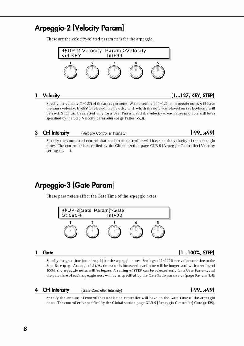
Arpeggio-2 [Velocity Param]These are the velocity-related parameters for the arpeggio.
1 Velocity [1...127, KEY, STEP]Specify the velocity (1~127) of the arpeggio notes. With a setting of 1~127, all arpeggio notes will havethe same velocity. If KEY is selected, the velocity with which the note was played on the keyboard willbe used. STEP can be selected only for a User Pattern, and the velocity of each arpeggio note will be asspecified by the Step Velocity parameter (page Pattern-5,3).
3 Ctrl Intensity (Velocity Controller Intensity) [-99...+99]Specify the amount of control that a selected controller will have on the velocity of the arpeggionotes. The controller is specified by the Global section page GLB-6 [Arpeggio Controller] Velocitysetting (p.139).
Arpeggio-3 [Gate Param]These parameters affect the Gate Time of the arpeggio notes.
1 Gate [1...100%, STEP]Specify the gate time (note length) for the arpeggio notes. Settings of 1~100% are values relative to theStep Base (page Arpeggio-1,1). As the value is increased, each note will be longer, and with a setting of100%, the arpeggio notes will be legato. A setting of STEP can be selected only for a User Pattern, andthe gate time of each arpeggio note will be as specified by the Gate Ratio parameter (page Pattern-5,4).
4 Ctrl Intensity (Gate Controller Intensity) [-99...+99]Specify the amount of control that a selected controller will have on the Gate Time of the arpeggionotes. The controller is specified by the Global section page GLB-6 [Arpeggio Controller] Gate (p.139).
1 2 3 4 5
UP-3[Gate Param]>GateGt:080% Int+00
UP-2[Ve loc i ty Param]>Veloc i tyVel:KEY Int+99

9
3.A
RPEG
GIA
TOR
PATTER
N D
EFINE
MO
DE
1 2 3 4 5
Arpeggio-4 [Pattern Copy]* This is displayed when a Preset Pattern is selected.This copies the identically-numbered Preset Pattern from a data card into the currentlyselected Preset Pattern. Press the ENTER key to execute.
Pattern-4 [User Pat Param]These settings determine the order in which notes of a User Pattern are sounded.
2 Arpeggio Type [As_Played...UP&DOWN]This determines the relation between the arpeggio notes played on the keyboard and the Tone (pagePattern-5,3) of each step.
As_Played :If the Tone of a step exceeds the number of specified arpeggio notes (played on the keyboard), that stepwill not sound.As_Played(FILL) :If the Tone of a step exceeds the number of specified arpeggio notes (played on the keyboard), the lastarpeggio note (the last-played note if Sort:OFF, or the lowest note if Sort:ON) will be sounded.Running_UP :If the Tone of a step exceeds the number of specified arpeggio notes (played on the keyboard),arpeggiation will return to the first arpeggio note (the first-played note if Sort:OFF, or the lowest note ifSort:OFF).UP&DOWN :If the Tone of a step exceeds the number of specified arpeggio notes (played on the keyboard),arpeggiation will return backward from the last arpeggio note.
Example) If for Step Number (page Pattern-5,1) #05 Tone has been set to LOOP (so that Tone 1~4 will bearpeggiated repeatedly):If 3 notes are prIessed with As_Played: 1 → 2 → 3 → rest → 1 → 2 → 3 → rest → 1 …If 3 notes are pressed with As_Played(FILL): 1 → 2 → 3 → 3 → 1 → 2 → 3 → 3 → 1 …If 3 notes are pressed with Running_UP: 1 → 2 → 3 → 1 → 1 → 2 → 3 → 1 → 1 …If 3 notes are pressed with UP&DOWN: 1 → 2 → 3 → 2 → 1 → 2 → 3 → 2 → 1 …
1 2 3 4 5
UP-4[Pattern Copy] Card:UP UP <Press ENTER >
PAT1-4[User Pat Param]>Arpeggio Type Type:AS–Played OctAlt:UP
10
5 Oct Alternation (Octave Alternation) [UP, DOWN, UP&DOWN]This specifies how arpeggiation will operate when the OCTAVE switch is set to 2~4 octaves.UP: Repeated ascent within the specified number of octaves.DOWN: Repeated descent within the specified number of octaves.UP&DOWN: Repeated ascent and descent within the specified number of octaves.
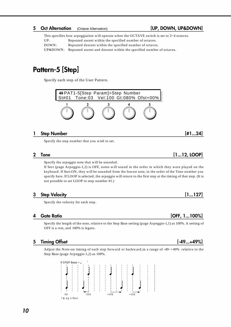
Pattern-5 [Step]Specify each step of the User Pattern.
1 Step Number [#1...24]Specify the step number that you wish to set.
2 Tone [1...12, LOOP]Specify the arpeggio note that will be sounded.If Sort (page Arpeggio-1,2) is OFF, notes will sound in the order in which they were played on thekeyboard. If Sort:ON, they will be sounded from the lowest note, in the order of the Tone number youspecify here. If LOOP is selected, the arpeggio will return to the first step at the timing of that step. (It isnot possible to set LOOP to step number #1.)
3 Step Velocity [1...127]Specify the velocity for each step.
4 Gate Ratio [OFF, 1...100%]Specify the length of the note, relative to the Step Base setting (page Arpeggio-1,1) as 100%. A setting ofOFF is a rest, and 100% is legato.
5 Timing Offset [-49...+49%]Adjust the Note-on timing of each step forward or backward,in a range of -49~+49% relative to theStep Base (page Arpeggio-1,2) as 100%.
Step Bass= の場合�
Timing Offset0% -25% +49% +33%
1 2 3 4 5
PAT1-5[Step Param]>Step NumberSt#01 Tone:03 Vel:100 Gt:080% Ofst+00%
If STEP Base = �
11
3.A
RPEG
GIA
TOR
PATTER
N D
EFINE
MO
DE
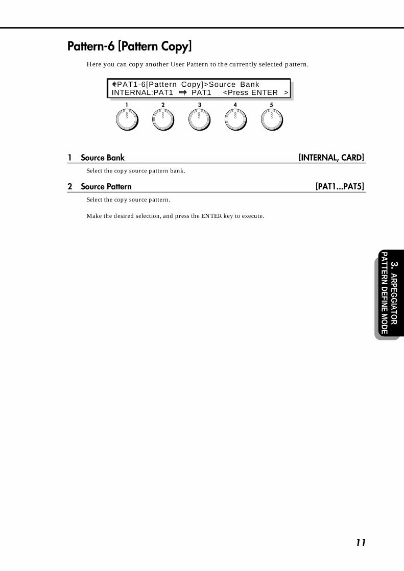
Pattern-6 [Pattern Copy]Here you can copy another User Pattern to the currently selected pattern.
1 Source Bank [INTERNAL, CARD]Select the copy source pattern bank.
2 Source Pattern [PAT1...PAT5]Select the copy source pattern.
Make the desired selection, and press the ENTER key to execute.
1 2 3 4 5
PAT1-6[Pattern Copy]>Source BankINTERNAL:PAT1 PAT1 <Press ENTER >

12
4.EDIT MODE
4-1. OSC SectionOSC-cmn1 [Oscillator Set]
Select one of 12 combinations (oscillator sets) to determine which of seven oscillator types(Standard Oscillator, Comb Filter Oscillator, VPM Oscillator, (Cross/Sync/Ring) ModulationOscillator, Brass Model Oscillator, Reed Model Oscillator, and Plucked String Oscillator) willbe used for each oscillator 1 and 2.
1 Oscillator Set [SET1...SET12]Select a set 1~12 to determine the oscillator type for oscillator 1 and 2. Sets 1~9 use two oscillators (1 and2). Sets 10~12 use only oscillator 1. (However since the pitch-related parameters for oscillator 2 will bestill valid, they can be used to control the pitch of the sub oscillator.)
Set Oscillator 1 Oscillator 2Set 1Set 2Set 3Set 4Set 5Set 6Set 7Set 8Set 9Set 10Set 11Set 12
Standard OSCStandard OSCStandard OSCStandard OSCComb Filter OSCComb Filter OSCComb Filter OSCVPM OSCVPM OSCBrass OSCReed OSCPluck OSC
Standard OSCComb Filter OSCVPM OSCModulation OSCComb Filter OSCVPM OSCModulation OSCVPM OSCModulation OSCno oscillator (OSC2)no oscillator (OSC2)no oscillator (OSC2)
Make the desired selection, and press the ENTER key to execute.
For details on each oscillator type, refer to the following pages.Standard Oscillator - p.23, Comb Filter Oscillator - p.26, VPM Oscillator - p.30, (Cross/Sync/Ring)Modulation Oscillator - p.36, Brass Model Oscillator - p.40, Reed Model Oscillator - p.46, Plucked StringOscillator - P.40
1 2 3 4 5
OSC-cmn1[Osci lator Set] SET01:Std.OSC+Std.OSC
4-1. OSC Section4-2. WAVE SHAPE Section4-3. MIXER Section4-4. FILTER Section4-5. AMPLIFIER Section
4-6. EFFECT Section4-7. EG Section4-8. LFO Section4-9. COMMON Section4-10.GLOBAL Section

13
4-1.O
SC
Sectio
n
1 2 3 4 5
OSC-cmn2 [Pitch EG Level] Pitch EGOSC-cmn2~4 contain Pitch EG settings. The Pitch EG controls the way in which the oscillatorpitch changes over time.The Pitch EG of the Prophecy can also be used as a general-purpose controller, meaning thatit can provide time-varying control over a variety of other parameters in addition to the pitch.
The settings here will determine the amounts of pitch change that occur in response topressing and releasing a key.In order to use the Pitch EG to control the pitch, you need to make Pitch EG settings in PitchModulation EG (page OSC 1-2,2 / OSC2-2,2) and set the depth of the effect in Pitch Mod.Intensity (page OSC 1-2,3 / OSC 2-2,3).
Key-off
Attack level
Key-on
Attacktime
Decaytime
Slopetime
Releasetime
Time
Break level
Pitch
+99
–99
Settings for time-dependent pitch change
1 Start Level [-99...+99]Specify the pitch level when the note is pressed (key-on). Positive (+) settings will cause the pitch to behigher than the standard pitch, and negative (–) settings will cause the pitch to be lower than thestandard pitch.
•PE1
2 Attack Level [-99...+99]Specify the pitch level that will be reached after the Attack Time. (Refer to the explanation for StartLevel.)
•PE3
3 Break Level [-99...+99]Specify the pitch level that will be reached after the Decay Time has elapsed. (Refer to the explanationfor Start Level.)
•PE5
5 Release Level [-99...+99]Specify the pitch level that will be reached when the Release Time has elapsed after key-off. (Refer tothe explanation for Start Level.)
•PE8
* After the Slope Time has elapsed until you release the note (Key-off), the pitch will be at the standardpitch.
OSC-cmn2[PitchEG Level]>Start LevelStaL+00 AtkL+99 BrkL-30 RlsL-30
4. ED
ITM
OD
E

14
OSC-cmn3 [Pitch EG Time] Pitch EGSpecify the time over which the oscillator pitch will change in response to a note beingpressed and released.
2 Attack Time [0...99]Specify the time over which the pitch will change from key-on (pressing a key) until the pitch of theAttack Level is reached. With a setting of 0, the pitch will change instantly. With a setting of 99, thepitch will change slowly.
•PE2
3 Decay Time [0...99]Specify the time over which the pitch will change from the Attack Level to the Break Point. (Refer to theexplanation for Attack Time.)
•PE4
4 Slope Time [0...99]Specify the time over which the pitch will return from the Break Level to the standard pitch. (Refer tothe explanation for Attack Time.)
•PE6
5 Release Time [0...99]Specify the time over which the pitch will change after key-off (releasing a key) until the Release Levelis reached. (Refer to the explanation for Attack Time.)
•PE7
1 2 3 4 5
OSC-cmn3[PitchEG Time]>Attack Time AtkT:00 DcyT:00 SlpT:00 RlsT:00
15
4-1.O
SC
Sectio
n
OSC-cmn4 [Pitch EG Ctrl]Pitch EG Keyboard Tracking/Velocity Control
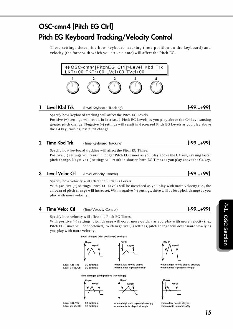
These settings determine how keyboard tracking (note position on the keyboard) andvelocity (the force with which you strike a note) will affect the Pitch EG.
1 Level Kbd Trk (Level Keyboard Tracking) [-99...+99]Specify how keyboard tracking will affect the Pitch EG Levels.Positive (+) settings will result in increased Pitch EG Levels as you play above the C4 key, causinggreater pitch change. Negative (–) settings will result in decreased Pitch EG Levels as you play abovethe C4 key, causing less pitch change.
2 Time Kbd Trk (Time Keyboard Tracking) [-99...+99]Specify how keyboard tracking will affect the Pitch EG Times.Positive (+) settings will result in longer Pitch EG Times as you play above the C4 key, causing fasterpitch change. Negative (–) settings will result in shorter Pitch EG Times as you play above the C4 key.
3 Level Veloc Ctl (Level Velocity Control) [-99...+99]Specify how velocity will affect the Pitch EG Levels.With positive (+) settings, Pitch EG Levels will be increased as you play with more velocity (i.e., theamount of pitch change will increase). With negative (–) settings, there will be less pitch change as youplay with more velocity.
4 Time Veloc Ctl (Time Velocity Control) [-99...+99]Specify how velocity will affect the Pitch EG Times.With positive (+) settings, pitch change will occur more quickly as you play with more velocity (i.e.,Pitch EG Times will be shortened). With negative (–) settings, pitch change will occur more slowly asyou play with more velocity.
Level changes (with positive (+) settings)
Key-onKey-off
Key-on Key-on
Key-off Key-off
EG settingsEG settings
when a low note is playedwhen a note is played softly
when a high note is played stronglywhen a note is played strongly
when a low note is playedwhen a note is plaed softly
when a high note is played stronglywhen a note is played storngly
Time changes (with positive (+) settings)
Key-onKey-off
Key-on
Key-off
Key-on
Key-off
EG settingsEG settings
Level Kdb TrkLevel Veloc. Ctl
Level Kdb TrkLevel Veloc. Ctl
1 2 3 4 5
OSC-cmn4[PitchEG Ctrl]>Level Kbd TrkLKTr+00 TKTr+00 LVel+00 TVel+00

16
OSC-cmn5 [Pitch Bend]Pitch Bender/After Touch Bending
These parameters let you specify the direction and amount of the pitch change controlled bythe Pitch Bender and Aftertouch (pressing the keyboard after playing a note).To control these using WHEEL 1,2,3, the Ribbon controller, or the Foot Pedal, make settings inCommon section, CMN-5~8.
1 PB Intensity(+X) (Pitch Bender Intensity (+X)) [–60...+12]Specify the amount (in chromatic steps) and the direction of the pitch change that will occur when thePitch Bender is moved in the positive (+) direction. With positive (+) settings the pitch will rise, andwith negative (–) the pitch will fall. A setting of 12 allows 1 octave of change.
2 PB Step(+X) (Pitch Bender Step (+X)) [0, /8, /4, /2, 1...12]Specify the type of pitch change that will occur when the Pitch Bender is moved in the positive (+)direction. For each setting of this parameter, the pitch will change as follows.
0 Continuous → smooth change/8 1/8 → change in units of 1/8 chromatic step/4 1/4 → change in units of 1/4 chromatic step/2 1/2 → change in units of 1/2 chromatic step1...12 1~12 → change in units of the specified number of chromatic steps (maximum of 1 octave)
If the Pitch Bender Step (+X) pitch is greater than the pitch specified for Pitch Bender Intensity(+X), the pitch will not change.
3 PB Intensity(-X) (Pitch Bender Intensity (–X)) [–60...+12]Specify the amount (in chromatic steps) and the direction of the pitch change that will occur when thePitch Bender is moved in the negative (-) direction. With positive (+) settings the pitch will rise, andwith negative (-) the pitch will fall. A setting of 12 allows 1 octave of change.
4 PB Step(-X) (Pitch Bender Step (–X)) [0, /8, /4, /2, 1...12]Specify the type of pitch change that will occur when the Pitch Bender is moved in the negative (-)direction. For each setting of this parameter, the pitch will change as explained in Pitch Bender Step(+X), above.
If the Pitch Bender Step (-X) pitch is greater than the pitch specified for Pitch Bender Intensity(-X), the pitch will not change.
5 AfterTouchBending (After Touch Bending) [–12...+12]Specify the amount (in chromatic steps) and the direction of pitch bend that will occur in response toAftertouch. With positive (+) settings Aftertouch will raise the pitch, and with negative (-) settings willlower the pitch.
1 2 3 4 5
OSC-cmn5[Pi tchxBend]>PBxIntensi ty(+X)(+ ) :+02x+Stp :0xx ( - ) : -02x -S tp :0xxATch+00
17
4-1.O
SC
Sectio
n
1 2 3 4 5
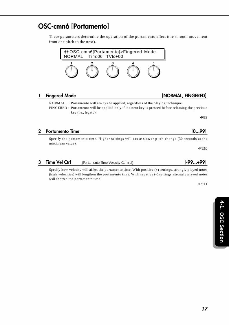
OSC-cmn6 [Portamento]These parameters determine the operation of the portamento effect (the smooth movementfrom one pitch to the next).
1 Fingered Mode [NORMAL, FINGERED]NORMAL : Portamento will always be applied, regardless of the playing technique.FINGERED : Portamento will be applied only if the next key is pressed before releasing the previous
key (i.e., legato).•PE9
2 Portamento Time [0...99]Specify the portamento time. Higher settings will cause slower pitch change (30 seconds at themaximum value).
•PE10
3 Time Vel Ctrl (Portamento Time Velocity Control) [-99...+99]Specify how velocity will affect the portamento time. With positive (+) settings, strongly played notes(high velocities) will lengthen the portamento time. With negative (–) settings, strongly played noteswill shorten the portamento time.
•PE11
OSC-cmn6[Portamento]>Fingered ModeNORMAL Tim:06 TVlc+00

18
OSC-cmn7 OSC MenuThis is the oscillator menu page.
The displayed menu items will depend on the setting of OSC-cmn1 [Oscillator Set].
1 [ STD1 ], [ COMB1], [ VPM1 ], [Brass ], [ Reed ], [Pluck ] (Oscillator 1)
2 [ STD2 ], [ COMB2], [ VPM2 ], [ MOD2 ], [ OSC2 ] (Oscillator 2)
3 [SUBOSC] (Sub Oscillator)
4 [NOISE] (Noise Generator)
5 [ UTY ] (Utility)
Here you can select the item you wish to edit; Oscillator 1, Oscillator 2, Sub Oscillator, Noise Generator,or Utility.For Oscillator 1 and 2, the oscillator type selected by Oscillator Set (page OSC-cmn1,1) will bedisplayed, and you can make settings for that oscillator type. [STD1] and [STD2] edit the Standard OSC(p.23), [COMB1] and [COMB2] edit the Comb Filter OSC (p.26), [VPM1] and [VPM2] edit the VPM OSC(p.30), [MOD2] edits the (Cross/Sync/Ring) Modulation OSC (p.36), [Brass] edits the Brass OSC (p.40),[Reed] edits the Reed OSC (p.46), and [Pluck] edits the Pluck OSC (p.50). If Oscillator Set is set to SET10~12 (Brass OSC, Reed OSC, Pluck OSC), Oscillator 2 will be displayed as [OSC2]. This is not anoscillator, but contains settings that specify the sub oscillator's basic pitch and pitch modulation.[SUBOSC] edits sub oscillator settings, and [NOISE] edits noise generator settings. [UTY] allows you toinitialize and copy oscillator-related settings.Use the CURSOR keys or the knobs to select the item you wish to edit, and press the ENTER key toenter each item.
1 2 3 4 5
OSC-cmn7[OSC Menu] (Turn & Press ENTER)[ STD1 ][ STD2 ][SUBOSC] [NOISE] [ UTY ]

19
4-1.O
SC
Sectio
n
Oscillator 1, Oscillator 2Here you can make settings for each oscillator type. Oscillator 1 pages OSC1-1~4 and oscillator 2 pagesOSC2-1~4 contain settings that determine the basic pitch of the oscillator, and are organized in thesame way for all oscillator types. From pages OSC1-5 and OSC2-5, the parameter structure will bedifferent for each oscillator type. However oscillator 2's [OSC2] contains settings for the pitch of the suboscillator, consists of pages OSC2-1~4.
OSC1-1 [Basic Pitch]These parameters specify the basic pitch of oscillator 1.
1 Octave [32"...4"]Set the basic pitch of oscillator 1 in octave units. A setting of 32" is 2 octaves down, 16" is 1 octave down,8" is the standard pitch, and 4" is 1 octave up.
•PE12 : OSC1 •PE18 : OSC2
2 Semi Tone [-12...+12]This is an adjustment in semitone units to the basic pitch specified by the Octave setting.
•PE13 : OSC1 •PE19 : OSC2
3 Fine Tune [-50...+50cent]This is a fine adjustment to the basic pitch in steps of 1 cent.
•PE14 : OSC1 •PE20 : OSC2
5 Frequency Offset [-10.0...+10.0Hz]This is a fine adjustment to the basic pitch in steps of 0.1 Hz.
•PE15 : OSC1 •PE21 : OSC2
For oscillator types which use a physical model, “Frequency Offset” settings can result inunstable oscillation.
1 2 3 4 5
OSC1-1[Basic Pitch]>OctaveOct:32" Semi+00 Fine+00 Ofst+00.0[Hz]

20
OSC1-2 [Pitch Modulation]These parameters specify how modulation will control the basic pitch of oscillator 1.
2 Mod.Src (Pitch Modulation Source) [OFF...CChg#95]Select the modulation source that will control the pitch. (Refer to 6.3 Modulation Source List.)
3 Mod.Int (Pitch Mod.Intensity) [-99...+99]Specify the depth and direction of the pitch change that can be controlled by the Pitch ModulationSource.
•PE17 : OSC1 •PE23 : OSC2
1 2 3 4 5
OSC1-2[Pitch Modulat ion]>Mod.Src P i tchEG:Int -99

21
4-1.O
SC
Sectio
n
1 2 3 4 5
OSC1-3 [Pitch Slope]These parameters specify how keyboard tracking (keyboard location) will affect the basicpitch of oscillator 1.
1 Low Key [C-1...G9]Specify the key at which Lower keyboard tracking will begin.
2 High Key [C-1...G9]Specify the key at which Higher keyboard tracking will begin.
3 Lower Intensity [–1.0...+2.0]Specify the depth and direction of the pitch change that will occur for the area of the keyboard belowthe Low Key.
4 Higher Intensity [–1.0...+2.0]Specify the depth and direction of the pitch change that will occur for the area of the keyboard abovethe High Key.
C-1 C4 C9C-1
C9
Low Key
High Key
Int= 0
Int= 0
Pitch
Keyboard position
Int=+2.0Int=+1.0
Int=-1.0
Int=-1.0
Int=+1.0 Int=+2.0
If Higher Intensity or Lower Intensity is set to a value of +2.0, playing one octave higher (within thearea specified by High Key and Low Key) will produce in a pitch two octaves higher. With a setting of-1.0, playing one octave higher (within the specified area) will produce a pitch one octave lower. Witha setting of 0.0, the pitch will remain fixed within the specified area. If you wish to play normal pitches,set Intensity to +1.0. The area between Low Key and High Key will always produce normal pitches.
OSC1-3[Pitch Slope]>Low KeyLK:C-1XXHK:C-1 LI-1.00 HI-1.00
22
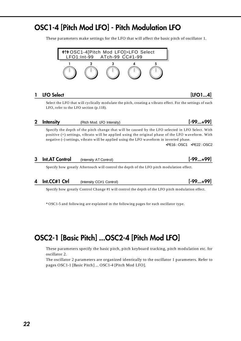
OSC1-4 [Pitch Mod LFO] - Pitch Modulation LFOThese parameters make settings for the LFO that will affect the basic pitch of oscillator 1.
1 LFO Select [LFO1...4]Select the LFO that will cyclically modulate the pitch, creating a vibrato effect. For the settings of eachLFO, refer to the LFO section (p.118).
2 Intensity (Pitch Mod. LFO Intensity) [-99...+99]Specify the depth of the pitch change that will be caused by the LFO selected in LFO Select. Withpositive (+) settings, vibrato will be applied using the original phase of the LFO waveform. Withnegative (–) settings, vibrato will be applied using the LFO waveform in inverted phase.
•PE16 : OSC1 •PE22 : OSC2
3 Int.AT Control (Intensity AT Control) [-99...+99]Specify how greatly Aftertouch will control the depth of the LFO pitch modulation effect.
4 Int.CC#1 Ctrl (Intensity CC#1 Control) [-99...+99]Specify how greatly Control Change #1 will control the depth of the LFO pitch modulation effect.
* OSC1-5 and following are explained in the following pages for each oscillator type.
OSC2-1 [Basic Pitch] ...OSC2-4 [Pitch Mod LFO]These parameters specify the basic pitch, pitch keyboard tracking, pitch modulation etc. foroscillator 2.The oscillator 2 parameters are organized identically to the oscillator 1 parameters. Refer topages OSC1-1 [Basic Pitch] ... OSC1-4 [Pitch Mod LFO].
1 2 3 4 5
OSC1-4[Pitch Mod LFO]>LFO Select LFO1:Int-99 ATch-99 CC#1-99

23
4-1.O
SC
Sectio
n
Standard OscillatorThis oscillator produces the sawtooth, pulse, and ramp waveforms used by analogsynthesizers.Either sawtooth or pulse wave will be selected as the main waveform, and ramp wave will bemixed with this for output. The levels of both can be adjusted independently.
* These parameters are displayed when you select Set 1~4 for the page OSC-cmn1 [Oscillator Set]parameter.
Waveform ModulationAnalog synthesizers of the past etc. had a function called Pulse Width Modulation (PWM), whichchanged the pulse width of a pulse wave over time. However, Waveform Modulation is an extension ofthis which can modulate the waveform of not only pulse waves, but also sawtooth waves or rampwaves.
Sawtooth waveWaveform Modulation can be applied to modify the waveform as shown below, creating changes intone color over time. When modulation is at 0, the basic sawtooth wave is produced. When modulationis at 99, a sawtooth wave of double the frequency is produced. If the modulation value is negative, thewaveform will be affected in the way opposite from positive values.
-99 -33 0 33 66 99
Pulse waveWaveform (Pulsewidth) Modulation can be applied to modify the waveform as shown below, creatingchanges in tone color over time. When modulation is at 0, a square wave is produced. Whenmodulation is at 99, the pulse width will be 0 and there will be no sound. If the modulation value isnegative, the waveform will be affected in the way opposite from positive values.
-99 -33 0 33 66 99
Ramp waveWaveform Modulation can be applied to modify the waveform as shown below, creating changes intone color over time. When modulation is at 0, a triangle wave is produced. As the modulation valueincreases, the waveform becomes a ramp wave (a waveform with a two-stage broken slope). With avalue of 50 a trapezoid waveform will result, and a value of 99 will once again produce a trianglewaveform. If the modulation value is negative, the waveform will be affected in the way opposite frompositive values.Compared to sawtooth and square waves, ramp waves have fewer overtones and a strongerfundamental, making them especially suitable for bass sounds, etc.
-99 -25 0 25 50 75 99
24
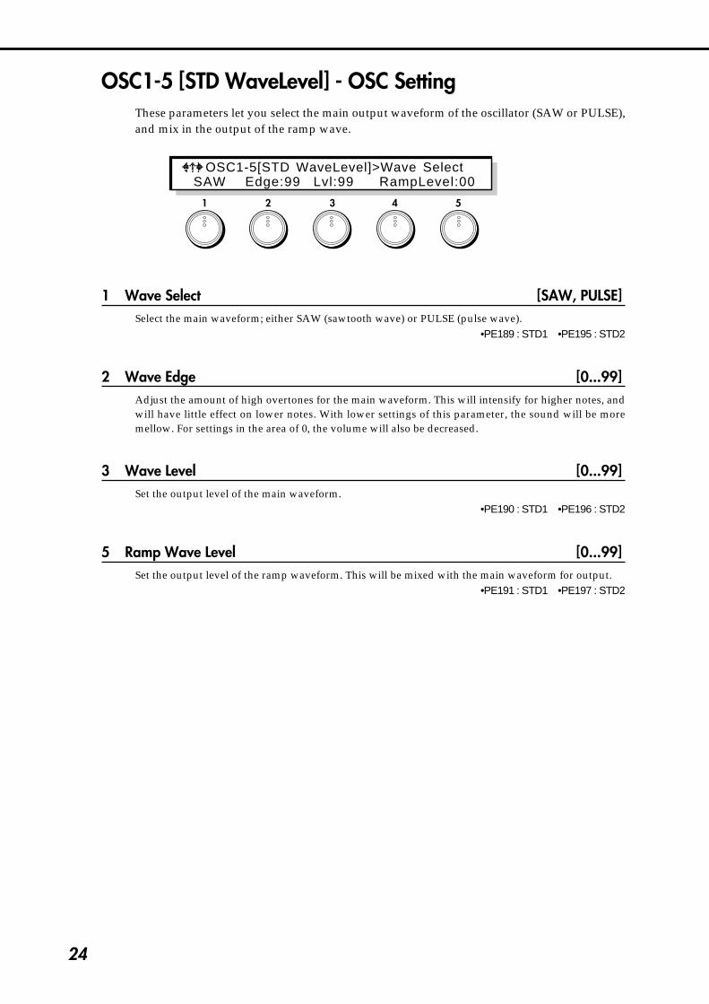
OSC1-5 [STD WaveLevel] - OSC SettingThese parameters let you select the main output waveform of the oscillator (SAW or PULSE),and mix in the output of the ramp wave.
1 Wave Select [SAW, PULSE]Select the main waveform; either SAW (sawtooth wave) or PULSE (pulse wave).
•PE189 : STD1 •PE195 : STD2
2 Wave Edge [0...99]Adjust the amount of high overtones for the main waveform. This will intensify for higher notes, andwill have little effect on lower notes. With lower settings of this parameter, the sound will be moremellow. For settings in the area of 0, the volume will also be decreased.
3 Wave Level [0...99]Set the output level of the main waveform.
•PE190 : STD1 •PE196 : STD2
5 Ramp Wave Level [0...99]Set the output level of the ramp waveform. This will be mixed with the main waveform for output.
•PE191 : STD1 •PE197 : STD2
1 2 3 4 5
OSC1-5[STD WaveLevel]>Wave Select SAW Edge:99 Lvl:99 RampLevel:00
25
4-1.O
SC
Sectio
n
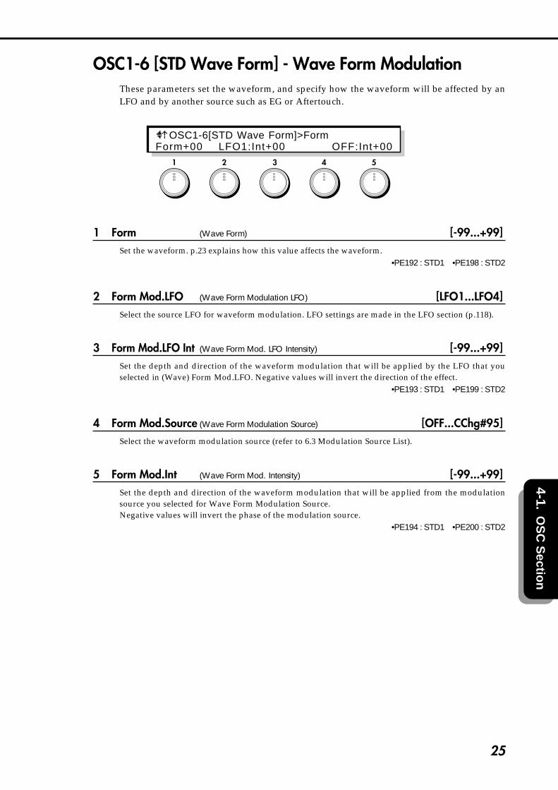
OSC1-6 [STD Wave Form] - Wave Form ModulationThese parameters set the waveform, and specify how the waveform will be affected by anLFO and by another source such as EG or Aftertouch.
1 Form (Wave Form) [-99...+99]Set the waveform. p.23 explains how this value affects the waveform.
•PE192 : STD1 •PE198 : STD2
2 Form Mod.LFO (Wave Form Modulation LFO) [LFO1...LFO4]Select the source LFO for waveform modulation. LFO settings are made in the LFO section (p.118).
3 Form Mod.LFO Int (Wave Form Mod. LFO Intensity) [-99...+99]Set the depth and direction of the waveform modulation that will be applied by the LFO that youselected in (Wave) Form Mod.LFO. Negative values will invert the direction of the effect.
•PE193 : STD1 •PE199 : STD2
4 Form Mod.Source (Wave Form Modulation Source) [OFF...CChg#95]Select the waveform modulation source (refer to 6.3 Modulation Source List).
5 Form Mod.Int (Wave Form Mod. Intensity) [-99...+99]Set the depth and direction of the waveform modulation that will be applied from the modulationsource you selected for Wave Form Modulation Source.Negative values will invert the phase of the modulation source.
•PE194 : STD1 •PE200 : STD2
1 2 3 4 5
OSC1-6[STD Wave Form]>FormForm+00 LFO1:Int+00 OFF:Int+00

26
COMB Filter OscillatorThe Comb Filter Oscillator inputs noise and an oscillator waveform into a comb filter, andproduces characteristic changes in sound when the feedback level of the filter is modified.When noise is input, increasing the feedback level of the comb filter will cause the sound tohave a progressively clearer sense of pitch.
* These parameters will be displayed when you have selected Set 2 or 5~7 for page OSC-cmn1[Oscillator Set].
Input Osc
Noise Delay
Loop LPF
Input Wave Level
Noise Level
Input Gain
Comb Filter Feedback
Comb Filter
FIG.1 Comb Oscillator Block
Frequency
Level
Frequency characteristicsof a sawtooth wave
This frequency will be heardas the pitch (the first partial).
Frequency
Level
Frequency characteristics of white noise(when the comb filter feedback gain is 0)
Frequency
Level
Frequency characteristicswhen the comb filter feedback gain is raised
FIG.2
FIG.3

27
4-1.O
SC
Sectio
n
OSC1-5 [COMB Input]These parameters set the levels of the noise and oscillator that are input into the comb filter.
1 Noise Level [0...99]Specify the noise volume level that will be input into the comb filter.
•PE201 : COMB1 •PE207 : COMB2
2 Input Wave Form [SAW, SQU, TRI]Select the oscillator waveform that will be input into the comb filter.
3 Input Wave Level [0...99]Specify the oscillator volume level that will be input into the comb filter.
•PE202 : COMB1 •PE208 : COMB2
5 Input Gain [0...99]Specify the input level to the comb filter.
When Comb Filter Feedback (page OSC1-6,1 / OSC2-6,1) is increased from 0 toward 99, thesound may become distorted as 99 is approached. If this occurs, set this parameter to limit thelevel beforehand to minimize the differences in output level from the comb filter.
1 2 3 4 5
OSC1-5[COMB Input]>Noise LevelNoiseL:70 Wave:SAW Lvl:10 InGain:20

28
OSC1-6 [COMB Feedback]These parameters specify the Comb Filter Feedback level and the specify how EG andmodulation will control it.
1 Feedback (Comb Filter Feedback) [0...99]Set the feedback level of the comb filter. As this value is increased, the resonance of the comb filter willbecome higher, resulting in a more pitched sound. Conversely, with lower settings of this value, theinput signal will be output without modification, and if the input signal is noise, the output signal willhave no sense of pitch.
•PE203 : COMB1 •PE209 : COMB2
2 Feedback Mod.EG (Feedback Modulation EG) [EG1...4/P.EG/A.EG]Select the EG (envelope generator) that will create time-based change in Comb Filter Feedback. Fordetails on EG settings, refer to p.111 for EG1~4, p.13 for the P.EG, and p.84 for the A.EG.
3 Mod.EG Int (Feedback Mod. EG Intensity) [-99...+99]Specify the depth of the change produced by the EG that is selected in Feedback Modulation EG. Withpositive (+) settings, the standard polarity of the EG will be used. With negative (–) settings, the EGpolarity will be inverted.
•PE204 : COMB1 •PE210 : COMB2
4 Fbk Mod.Source (Feedback Modulation Source) [OFF...CChg#95]Select the modulation source that will control Comb Filter Feedback. (Refer to 6.3 Modulation SourceList.)
5 Fbk Mod.Int (Feedback Modulation Intensity) [-99...+99]Specify the depth and direction of the effect produced by the modulation source selected in FeedbackModulation Source. Positive (+) settings will allow the Comb Filter Feedback value to be increased, andnegative (–) settings will allow it to be decreased. If the Feedback Modulation Source parameter is set toEG or LFO, positive (+) settings will cause the standard polarity of the EG or LFO to be used, andnegative (–) settings will invert the polarity.
•PE205 : COMB1 •PE211 : COMB2
1 2 3 4 5
OSC1-6[COMB Feedback]>FeedbackFback:45 EG1:Int+25 OFF:Int+00

29
4-1.O
SC
Sectio
n
OSC1-7 [COMB Loop LPF Frequency]This parameter sets the cutoff frequency of the low pass filter located inside the comb filter.
1 Comb Loop LPF Frequency [0...99]Specify the cutoff frequency of the low pass filter located inside the comb filter. When this value is low,the high frequencies will be cut from the signal passing through the comb filter, resulting in a moremellow sound. Higher settings of this value will result in a more brilliant sound.
•PE206 : COMB1 •PE212 : COMB2
Depending on the settings of [COMB Feedback] (page OSC1-6 / OSC2-6) and this low passcutoff frequency setting, the output of the oscillator may be distorted. Also, if the feedback levelspecified by [COMB Feedback] is high when you change the value of this setting, a certainamount of time may be required for the filter to reach the value that you set. These situations aredue to the characteristics of the comb filter, and in such cases, you should lower either the[COMB Feedback] setting or the setting of this parameter.
1 2 3 4 5
OSC1-7[COMB Loop LPF Fc] Fc:10

30
VPM OscillatorIn this oscillator, the output of a carrier is phase-modulated by a modulator, passed througha wave shaping circuit to emphasize the high frequencies, and then output.By controlling the wave shaping parameters, you can create tonal changes that are differentthan those produced simply by phase modulation alone.
* These parameters will be displayed when Set 3, 6, 8, or 9 is selected in page OSC-cmn1 [Oscillator Set].
Modulator Pitch Carrier Pitch
Carrier Level
Output
Wave Shaping Parameters
Feedback Gain
Modulator Level
Modulator Carrier WaveShaping
CarrierThis is the waveform that determines the basic pitch and volume. For the carrier you can select sine(SIN), sawtooth (SAW), triangle (TRI) or square (SQU) waveforms, and this waveform will be phase-modulated by the modulator.
ModulatorThis is the waveform that modulates the carrier. VPM allows you to select from sine, sawtooth, triangle,or square wave oscillators to phase-modulate the carrier. Most commonly, an EG etc. is used to controlthe pitch of the modulator to create interesting changes in tone.
Wave ShapingThis section passes the value of the input waveform through a mathematical function and outputs theresult. The VPM oscillator uses a sine wave function that emphasizes specific high frequencies. Byadjusting the wave shaping parameters to control the frequency of this sine wave, you can modify thepoint at which the high frequencies will be emphasized.
OSC1-5 [VPM Carrier Wave]This parameter selects the carrier waveform.
1 VPM Carrier Wave [SIN, SAW, TRI, SQU]Select the carrier waveform.
•PE213 : VPM1 •PE226 : VPM2
1 2 3 4 5
OSC1-5[VPM Carrier Wave]Wave…SAW
(Basic Pitch)

31
4-1.O
SC
Sectio
n
OSC1-6 VPM CarrierThese parameters set the output level of the carrier, and determine the EG and modulationsettings.
1 Carrier Level [0...99]Set the output level of the carrier. This determines the output level of the VPM oscillator.
•PE214 : VPM1 •PE227 : VPM2
2 Level Mod.EG (Carrier Level Modulation EG) [EG1...4, P.EG, A.EG]Select the EG that will control the output level of the carrier. For the EG settings, refer to p.111 forEG1~4, p.13 for P.EG, and p.84 for A.EG.
3 Mod.EG Intensity (Carrier Level Modulation EG Intensity) [-99...+99]Specify the depth and direction in which the EG selected for Carrier Level Modulation EG will controlthe carrier level. Negative values will invert the polarity of the EG.
•PE215 : VPM1 •PE228 : VPM2
4 Level Mod.Source (Carrier Level Modulation Source) [OFF...CChg#95]Select the modulation source such as LFO or aftertouch (see 6.3 Modulation Source List) that willmodulate the output level of the carrier.
5 Level Mod.Int (Carrier Level Modulation Intensity) [-99...+99]Specify the depth of control that the modulation source specified as the Carrier Level ModulationSource will have on the carrier level. Negative values will invert the polarity of the modulation source.
•PE216 : VPM1 •PE229 : VPM2
1 2 3 4 5
OSC1-6[VPM Carr ier ]>Carr ier LevelCLvl:99 EG1:Int+00 OFF:Int+00

32
OSC1-7 [VPM Cari Shape]These parameters let you specify the characteristics of the mathematical function that addshigh frequencies to the carrier output waveform. The wave shaping function is a sine wave,and its frequency will depend on the Shape value.
1 Wave Shape (Wave Shape) [0...99]Increase or decrease the number of cycles in the wave shaping function. Higher values will cause theemphasis to be applied at a higher frequency, and higher partials to be added.
•PE217 : VPM1 •PE230 : VPM2
テーブル可変�Shaping: 0 99
2 Shape Mod.LFO (Wave Shape Modulation LFO) [LFO1...4]Select the modulation LFO for Wave Shape. This will produce an effect similar to wah or syncmodulation. For LFO settings, refer to the LFO section (p.118).
3 Mod.LFO Int (Wave Shape Mod. LFO Intensity) [-99...+99]Specify the depth and direction of the Wave Shape modulation applied by the selected Wave ShapeModulation LFO.
•PE218 : VPM1 •PE231 : VPM2
4 Shape Mod.Src (Wave Shape Modulation Source) [OFF...CChg#95]Select a source such as EG or Aftertouch that will modulate Shape. (Refer to 6.3 Modulation SourceList.)
5 Shape Mod.Int (Wave Shape Mod. Intensity) [-99...+99]Specify the depth and direction of the Wave Shape modulation applied by the selected Wave ShapeModulation Source.
•PE219 : VPM1 •PE232 : VPM2
1 2 3 4 5
OSC1-7[VPM CariShape]>Wave ShapeWShap:40 LFO1:Int+00 EG1:Int+99

33
4-1.O
SC
Sectio
n
OSC1-8 VPM Feedback GainThis parameter specifies the amount of the carrier output that will be fed back to themodulation input of the carrier.
2 VPM Feedback Gain [0...99]Specify the input level for the feedback that is returned from the carrier output to the carrier input. Theovertone structure will change as this value is increased. Increasing the value beyond a certain amountwill result in a noise-like sound.
•PE220 : VPM1 •PE233 : VPM2
OSC1-9 [VPM Modulator Pitch]These parameters let you make settings related to pitch, keyboard tracking, and modulationsource etc. of the modulator.
1 Semi Tone (Frequency Semi Tone) [–12...+96]Set the pitch of the modulator in semitone units. This setting is relative to the pitch of the carrier. Thebasic pitch of the carrier is determined by the OSC1-1 Basic Pitch parameter.
2 Fine Tune (Frequency Fine Tone) [–50...+50]Make fine adjustments to the modulator pitch. This setting is relative to the pitch of the carrier.
3 Kbd Trk (Modulator Pitch Keyboard Tracking) [–99...+99]Specify how keyboard tracking will affect the modulator pitch. With positive (+) values, notes will bepitched progressively sharper (higher) than the normal pitch as you play above C4, and progressivelyflatter (lower) than the normal pitch as you play below C4. With negative (–) values, higher notes willbe progressively flatter, and lower notes will be progressively sharper.
1 2 3 4 5
OSC1-8[VPM Feedback Gain]FeedbackGain:00
1 2 3 4 5
OSC1-9[VPM Modulator Pitch]>Semi ToneSemi+02 Fine+02 KTr+00 LFO2:Int+24

34
4 Mod.Src (Modulator Pitch Mod. Source) [OFF...CChg#95]Select the modulation source that will modulate the pitch of the modulator. (Refer to 6.3 ModulationSource List.) Normally, an EG is used for this purpose.
5 Mod.Int (Modulator Pitch Modulation Intensity) [–99...+99]Specify the depth and direction of the pitch modulation that is applied to the modulator under thecontrol of the modulation source selected in (Modulator Pitch) Mod.Src. With negative (–) values, thepolarity of the modulation source will be inverted.
•PE221 : VPM1 •PE234 : VPM2
OSC1-10 [VPM Modulator]These parameters select the waveform that will be used as the modulator, and set its level.
1 Wave (Modulator Wave) [SIN, SAW, TRI, SQU, OSC1/OSC2]Select the waveform that will be used as the modulator; sine (SIN), sawtooth (SAW), triangle (TRI),square (SQU) wave, or OSC (2 for OSC1, or 1 for OSC2).
•PE222 : VPM1 •PE235 : VPM2
2 Level (Modulator Level) [0...99]Set the output level of the modulator. With a setting of 0, no modulation will be applied to the carrier.As the value is increased the effect of modulation will intensify.
•PE223 : VPM1 •PE236 : VPM2
1 2 3 4 5
OSC1-10[VPM Modulator]>WaveWave:SAW Lvl:20

35
4-1.O
SC
Sectio
n
OSC1-11 [VPM Modulator Level]These parameters select the EG modulation source that will control the output level of themodulator.
1 Level Mod.EG (Modulator Level Modulation EG) [EG1...4, P.EG, A.EG]Select the EG that will control the output level of the modulator. For EG settings, refer to p.111 for EG1-4, p.13 for P.EG, and p.84 for A.EG.
2 Mod.EG Int (Modulator Level Mod. EG Intensity) [-99...+99]Specify the depth and direction by which the EG selected in Modulator Level Modulation EG willcontrol the modulator output level.
•PE224 : VPM1 •PE237 : VPM2
3 EG Int Kbd Trk (Modulator Level EG Intensity Keyboard Tracking) [-99...+99]Specify the depth and direction by which keyboard tracking will affect the EG control over modulatoroutput level. With positive (+) settings, the effect of the EG will increase as you play further above theC4 key, and decrease as you play further below the C4 key. With negative (–) settings, the effect of theEG will decrease above the C4 key, and increase below the C4 key.
4 Level Mod.Src (Modulator Level Modulation Source) [OFF...CChg#95]Specify the modulation source that will affect the output level of the modulator. (Refer to 6.3Modulation Source List.)
5 Level Mod.Int (Modulator Level Mod. Intensity) [-99...+99]Specify the depth and direction by which the modulation source specified in Modulator LevelModulation Source will affect the modulator. With negative (–) settings, the polarity of the modulationsource will be inverted.
•PE225 : VPM1 •PE238 : VPM2
1 2 3 4 5
OSC1-11[VPM Mod Level]>Level Mod.EG EG1:Int+79 KTr+00 OFF:Int+00

36
Cross/Sync/Ring Modulation OscillatorThis oscillator allows you to select one of three types of modulation commonly used in analogsynthesizers; sync, cross, and ring modulation.The modulation oscillator contains a carrier oscillator. This carrier waveform will bemodulated. The modulator waveform is not built-in, and you must select an output such asOSC1 as the modulation input. The modulation oscillator is fixed at OSC2.
* These parameters will be displayed when Set 4,7, or 9 has been selected in page OSC-com1 [OscillatorSet].
CarrierThe frequency and/or amplitude of this waveform is modulated by a modulator. All waveforms builtinto the Modulation Oscillator are used as carriers.
ModulatorIn general, "modulator" refers to a waveform which modulates the frequency and/or amplitude of acarrier. The Modulator Oscillator does not contain a modulator; it must be supplied from an externalsource through the modulation input.
Modulation inputThis selects the source of the modulator waveform. Select a modulator from the following threechoices.1. The output waveform of OSC1 (This will depend on the oscillator that is selected for OSC1.)2. Noise3. Feedback (This is the waveform that passes through the filter and amp and is output from the
Prophecy synthesizer, and will vary widely depending on the settings.)
SYNC MODULATIONThe modulator will be the master waveform, and the carrier the slave waveform which willsynchronize to the master.When the master waveform begins a new cycle (i.e., the moment it crosses the zero value line goingfrom positive to negative), the phase of the slave waveform will be reset to 0 and it will begin a newcycle. Either sawtooth or triangle can be selected as the slave waveform. This is usually used with apitch envelope etc. applied to the master waveform.
Sync Modulation
Modulator Wave
Carrier Wave
(Master)
(Slave)

37
4-1.O
SC
Sectio
n
CROSS MODULATIONThe modulator applies frequency modulation to the carrier. One of the following 3 waveforms can beselected as the carrier: sawtooth, sine, and square wave. This is usually used with a pitch envelopeapplied to the modulator.
Cross Modulation
Modulator
Cross Carrier Depth
Carrier Wave
RING MODULATIONThe output signal will consist of the product of the modulator and carrier. One of the following 3waveforms can be selected as the carrier; sawtooth, sine, and square wave. Since ring modulationproduces a metallic sound with little pitch content, it is suitable for special effects. Changes in tone arecreated by the differences in frequency between the carrier and modulator.
Ring Modulation
Modulator
Ring Mod WaveCarrier Wave
* The pitch of the carrier (the waveform built into the Modulation Oscillator) is determined by OSC1-1Basic Pitch. The pitch etc. of the modulator (OSC1, SUB OSC) is adjusted by the parameters for OSC1or SUB OSC.

38
OSC2-5 [MOD OSC Type]These parameters determine the modulation type and modulator input.
1 Modulation Type [RING, CROSS, SYNC]Select the type of modulation; RING (ring modulation), CROSS (cross modulation), or SYNC (syncmodulation). For an explanation of each type, refer to the p.36.
2 Input Select [OSC1, FBACK, NOISE]Select the modulator used for modulation.
OSC1 : The output waveform of OSC1 (This will depend on the oscillator that is selected for OSC1.)FBACK : Feedback (This is the waveform that passes through the filter and amp and is output from
the Prophecy synthesizer, and will vary widely depending on the settings.)NOISE : Noise
RING MODULATION: This will be displayed if the Modulation Type has been set to RING.
4 Carrier Select (Ring Carrier Select) [SIN, SAW, SQU]Select the waveform of the carrier (the modulation oscillator of the two waveforms that are multiplied)used for ring modulation; SIN (sine), SAW (sawtooth), or SQU (square).
•PE239
CROSS MODULATION: This will be displayed if the Modulation Type has been set to CROSS.
4 Carrier Select (Cross Carrier Select) [SIN, SAW, SQU]Select the waveform of the carrier for cross modulation; SIN (sine), SAW (sawtooth), or SQU (square).
•PE240
SYNC MODULATION: This will be displayed if the Modulation Type has been set to SYNC.
4 Sync Slave Select (Sync Carrier Select) [SAW, TRI]Select the carrier (slave) waveform used for sync modulation; SAW (sawtooth) or TRI (triangle).
5 Modulator Edge [0...99]This parameter controls the amount of overtones in the slave waveform. In cases such as when a pitchenvelope etc. raises the slave waveform to a high pitch, set this parameter to a low value to preventunpleasant overtones from being produced.
As this parameter is adjusted toward 0 the volume will decrease, and at 0 there will be silence.The effect of this parameter is most noticeable for high pitches of the slave waveform, and at lowpitches it will have less effect.
1 2 3 4 5
OSC2-5[MOD OSC Type]>Modulation TypeRING Input:OSC1 CariWave:SIN

39
4-1.O
SC
Sectio
n
When high pitches are played using Sync Modulation, the volume may decrease, and in somecases there may be no sound.
OSC2-6 [Modulator Cross Modulation]Cross Modulation allows you to specify the depth at which the modulator will applyfrequency modulation to the carrier, and specify how the cross modulation will be controlledby EG and by a selected modulation source.
These parameters are displayed when CROSS has been selected for OSC2-5 Modulation Type.
1 Modulation Depth (Cross Modulation Depth) [0...99]Adjust the depth at which the modulator will apply frequency modulation to the carrier. Higher valueswill produce heavier modulation.
•PE241
2 Mod.Depth Mod.EG (Cross Modulation Depth Modulation EG) [EG1...EG4, P.EG, A.EG]Select the EG that will control the depth of cross modulation. For EG 1~4 settings, refer to the EGsection.
3 EG Intensity (Cross Modulation EG Intensity) [0...99]Adjust the depth at which the EG will control the amount of cross modulation.
4 Depth Mod.Source (Cross Modulation Depth Modulation Source) [OFF...CChg#95]Select a modulation source that will control the depth of cross modulation. (Refer to 6.3 ModulationSource List.)
5 Depth Mod.Int (Depth Modulation Intensity) [+99...–99]Specify the depth and direction in which the modulation source specified for Cross Modulation DepthModulation Source will affect cross modulation depth.
1 2 3 4 5
OSC2-6[MOD Cross Mod]>Modulation DepthDepth:00 EG1:Int-99 OFF:Int-99

40
Brass Model OscillatorThis oscillator is a physical model that simulates a lip reed instrument such as a trumpet. Byusing controllers such as key velocity or the wheel to control Pressure (the force of breathapplied to the mouthpiece), you can achieve performance expression similar to an actual lipreed instrument. By modulating the characteristics of the reed, you can create tonal changeslike those produced by different playing techniques.
The parameters are divided into three groups: Pressure, which corresponds to the force of thebreath that is blown into the mouthpiece; Lip, which creates tonal change corresponding tothe shape and tension of the musician's lips; and Bell, which adjusts the tonal characteristicsdependent on the shape of the end of the instrument's bore.
This oscillator provides two types of pitch bending; Jump Bending which produces modejumps as on a trumpet (when valves are used to change the length of the bore), and SmoothBending as on a trombone (when the length of the bore is changed continuously).Settings for Jump Bend are made in OSC-cmn5 PB Intensity (+) and PB Intensity (–), andsettings for Smooth Bend are made using the Smooth Bending parameters of OSC1-5.
Lip (Character)specify tonal change resulting from lip shape
Inst Typeselect from models that simulate the different bore lengths and shapes of various instruments
Bell specify the shape of the end of the bore
{Pressure specify the force of the breath blown into the mouthpiece�Noise specify the amount of breath noise
For some parameter settings, the resulting pitch may not match the pitches of the keyboard.
When high pitches are played, the volume may decrease, and in some cases there may be nosound.
* These parameters are displayed if Set 10 has been selected in page OSC-cmn1 [Oscillator Set].

41
4-1.O
SC
Sectio
n
OSC1-5 [Brass Type]These parameters let you select the instrument type and make settings for Smooth Bending.
1 Instrument Type [TRUMPET1, TRUMPET2, TROMBONE, HORN]Select the instrument type. This selection determines characteristics of the instrument such as borelength and mouthpiece shape.
3 Smooth Bending Ctl (Smooth Bending Controller) [OFF...CChg#95]Select the controller that will control the smooth bending effect (Refer to 6.3 Modulation Source List), tocreate continuous changes in pitch.For example you could assign Wheel 1 to PBend+ (in Common section page CMN-5 Control Wheel 1)and use it to control Jump Bending, and assign Wheel 2 as the Smooth Bending controller. This wouldallow you to independently use both types of bending effect in a single program.
4 Smooth Bending Int (Smooth Bending Intensity) [0...12]Set the bend range of Smooth Bending up to a maximum of 1 octave.Jump Bend will use the setting of page OSC-cmn5 PB Intensity (+) and PB Intensity (–).
5 Smooth Bending Dir(Smooth Bending Direction) [UP, DOWN, BOTH]Specify the direction of the pitch bend controlled by the Smooth Bending Controller. If this parameter isset to UP or DOWN, the resulting pitch bend will be zero when the selected Smooth Bending Controlleris at zero (minimum) position, and will reach the maximum pitch bend specified by Smooth BendingIntensity when the controller is at 127 (maximum) position.The pitch will rise with a setting of UP, and fall with a setting of DOWN. If you select BOTH, zero pitchbend will occur when the controller selected as the Smooth Bending Controller is at the center position;the pitch will rise for controller positions above center, and fall for controller positions below center.For example if you have assigned Aftertouch to be the controller, applying aftertouch to the keyboardwill raise the pitch if UP is selected, and will lower the pitch if DOWN is selected. If BOTH is selected,zero pitch bend (standard pitch) will be reached when the aftertouch value reaches the halfway point.
1 2 3 4 5
OSC1-5[Brass Type]>Instrument TypeTRUMPET1 SmBnd[CChg#16:Int+12 UP ]

42
OSC1-6 [Brass Pressure EG]These parameters determine how EG and modulation source will control Pressure (the forceof breath blown into the mouthpiece), and set the level of breath noise.
1 EG (Pressure EG) [EG1...4, P.EG, A.EG]Select the EG that will control Pressure. For EG settings, refer to p.111 for EG 1~4, p.13 for P.EG, andp.84 for A.EG.
2 EG Intensity (Pressure EG Intensity) [–99...+99]Specify the depth of control that the EG selected as the Pressure EG will have on Pressure.
•PE243
3 Mod.Source (Pressure EG Intensity Modulation Source) [OFF...CChg#95]Select the modulation source that will control Pressure EG Intensity. (Refer to 6.3 Modulation SourceList.) This will control the effect of the envelope, and by selecting LFO you can simulate the vibrato thata brass player produces by varying the pressure of his breath.
4 Mod.Int (Pressure EG Intensity Mod.Intensity) [-99...+99]Specify the amount and direction of the change produced by the modulation source selected forPressure EG Intensity Modulation Source. With positive (+) settings the Pressure Intensity values willbe increased, and with negative (–) settings they will be decreased.
5 Noise Level [0...99]Set the volume level of the breath noise. Since this uses the signal from the noise generator, you can usethe low pass filter for the noise generator to adjust the tone of the noise (see page 58).
•PE247
1 2 3 4 5
OSC1-6[Brass PressureEG]>EG EG1:Int+00 CChg#01:Int+30 Noise:30

43
4-1.O
SC
Sectio
n
OSC1-7 [Brass Pressure Mod]These parameters let you make settings for the LFO and modulation source that controlsPressure (the force of the breath blown into the mouthpiece).
1 Mod.LFO (Pressure Modulation LFO) [LFO1...4]Select the LFO that will control Pressure. LFO settings are made in the Lfo section. By using aftertouchetc. to control the selected LFO you can apply vibrato in a more natural manner.
2 Mod.LFO Int (Pressure Modulation LFO Intensity) [–99...+99]Specify the depth of the modulation (vibrato) that will be applied to Pressure by the LFO selected forPressure Modulation LFO.
3 Mod.Source (Pressure Modulation Source) [OFF...CChg#95]Select the modulation source that will control Pressure. (Refer to 6.3 Modulation Source List.) IfAftertouch is selected here, breath pressure will increase when you press down on the keyboard. IfModulation Wheel is selected here, breath pressure will increase when you move the wheel in thepositive (+) direction. In this case, you can set Pressure EG Intensity (page OSC 1-6,2) to 0, and use onlythe modulation wheel to control the breath pressure and produce sound.
4 Mod.Int (Pressure Modulation Intensity) [–99...+99]Specify the depth and direction of the control applied to Pressure by the modulation source selected forPressure Modulation Source. With positive (+) settings, higher values of the Pressure ModulationSource will increase the Pressure. With negative (–) settings, lower values of the Pressure ModulationSource will increase the Pressure. If EG or LFO is selected as the Pressure Modulation Source, positive(+) settings will cause the original phase of the EG or LFO to be used, and negative (–) settings willinvert the phase.
* Selecting LFO as the Pressure EG Intensity Modulation Source (page OSC 1-6,4) is not the same thingas using the Pressure Modulation LFO. The former simulates the effect of the Pressure EG (page OSC1-6,4), and the LFO effect is proportionate to the value of the EG signal. This means that if the EGsignal is 0, there will be no effect. The latter (Pressure Modulation LFO) applies an LFO effect that isindependent of the EG, so the Pressure value will still be modulated even if the EG signal is 0.
1 2 3 4 5
OSC1-7[Brass PressureMod]>Mod.LFO LFO1:Int+06 EG1:Int+80
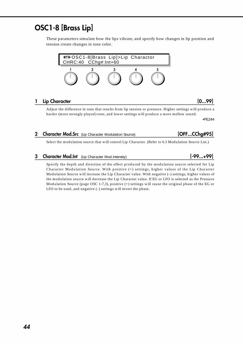
44
OSC1-8 [Brass Lip]These parameters simulate how the lips vibrate, and specify how changes in lip position andtension create changes in tone color.
1 Lip Character [0...99]Adjust the difference in tone that results from lip tension or pressure. Higher settings will produce aharder (more strongly played) tone, and lower settings will produce a more mellow sound.
•PE244
2 Character Mod.Src (Lip Character Modulation Source) [OFF...CChg#95]Select the modulation source that will control Lip Character. (Refer to 6.3 Modulation Source List.)
3 Character Mod.Int (Lip Character Mod.Intensity) [-99...+99]Specify the depth and direction of the effect produced by the modulation source selected for LipCharacter Modulation Source. With positive (+) settings, higher values of the Lip CharacterModulation Source will increase the Lip Character value. With negative (–) settings, higher values ofthe modulation source will decrease the Lip Character value. If EG or LFO is selected as the PressureModulation Source (page OSC 1-7,3), positive (+) settings will cause the original phase of the EG orLFO to be used, and negative (–) settings will invert the phase.
1 2 3 4 5
OSC1-8[Brass Lip]>Lip CharactorCHRC:40 CChg#:Int+60

45
4-1.O
SC
Sectio
n
OSC1-9 [Brass Bell]These parameters determine how the bell (bore end) of the brass instrument will affect thetone.
2 Bell Type [OPEN, MUTE]Specify the type of the bell. A setting of MUTE simulates the characteristic tone that occurs when ahand or a plastic mute is inserted into the bell to attenuate the acoustical output. A setting of OPEN isthe normal state.
3 Bell Tone [0...99]Adjust the tone of the bell. As this value is increased, the lower frequency range will decrease,producing a thinner tone.
•PE245
4 Bell Resonance [0...99]Adjust the level of emphasis that is applied at the frequency region specified by the Bell Tone setting.As this value is increased the resonance effect will be emphasized.
•PE246
1 2 3 4 5
OSC1-9[Brass Bel l ]>Bel l Type Type:OPEN Tone:00 Reso:00
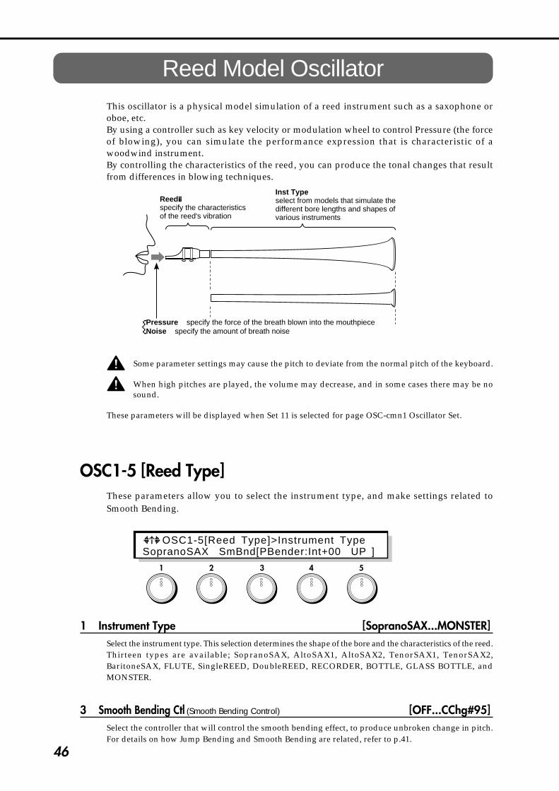
46
Reed Model OscillatorThis oscillator is a physical model simulation of a reed instrument such as a saxophone oroboe, etc.By using a controller such as key velocity or modulation wheel to control Pressure (the forceof blowing), you can simulate the performance expression that is characteristic of awoodwind instrument.By controlling the characteristics of the reed, you can produce the tonal changes that resultfrom differences in blowing techniques.
Inst Typeselect from models that simulate the different bore lengths and shapes of various instruments
Reed�specify the characteristics of the reed's vibration
Pressure specify the force of the breath blown into the mouthpieceNoise specify the amount of breath noise{
Some parameter settings may cause the pitch to deviate from the normal pitch of the keyboard.
When high pitches are played, the volume may decrease, and in some cases there may be nosound.
These parameters will be displayed when Set 11 is selected for page OSC-cmn1 Oscillator Set.
OSC1-5 [Reed Type]These parameters allow you to select the instrument type, and make settings related toSmooth Bending.
1 Instrument Type [SopranoSAX...MONSTER]Select the instrument type. This selection determines the shape of the bore and the characteristics of the reed.Thirteen types are available; SopranoSAX, AltoSAX1, AltoSAX2, TenorSAX1, TenorSAX2,BaritoneSAX, FLUTE, SingleREED, DoubleREED, RECORDER, BOTTLE, GLASS BOTTLE, andMONSTER.
3 Smooth Bending Ctl (Smooth Bending Control) [OFF...CChg#95]Select the controller that will control the smooth bending effect, to produce unbroken change in pitch.For details on how Jump Bending and Smooth Bending are related, refer to p.41.
1 2 3 4 5
OSC1-5[Reed Type]>Instrument TypeSopranoSAX SmBnd[PBender:Int+00 UP ]

47
4-1.O
SC
Sectio
n
4 Smooth Bending Int (Smooth Bending Intensity) [0...12]Specify the range of Smooth Bending (up to one octave).
5 Smooth Bending Dir(Smooth Bending Direction) [UP, DOWN, BOTH]Specify the direction of the pitch bend controlled by the Smooth Bending Controller. If this parameter isset to UP or DOWN, the resulting pitch bend will be zero when the selected Smooth Bending Controlleris at zero (minimum) position, and will reach the maximum pitch bend specified by the SmoothBending Intensity setting when the controller is at 127 (maximum) position.For details on the parameter values, refer to p.41.
OSC1-6 [Reed Pressure EG]These parameters let you select the EG that will control Pressure (the force of breath blowninto the reed) and specify a modulation source for it, and set the level of breath noise.
1 EG (Pressure EG) [EG1...4/P.EG/A.EG]Select the EG that will control Pressure. For EG settings, refer to p.111 for EG 1~4, p.13 for P.EG, andp.84 for A.EG.
2 EG Intensity (Pressure EG Intensity) [0...99]Set the depth of the effect that the EG selected for Pressure EG will have on Pressure.
•PE248
3 Mod.Source (Pressure EG Intensity Modulation Source) [OFF...CChg#95]Select the modulation source that will control Pressure EG Intensity. (Refer to 6.3 Modulation SourceList.) The selected modulation source will control the effect that the envelope has on Pressure. If youselect LFO as the modulation source, you can simulate the vibrato or growl effects produced on a windinstrument by varying breath pressure.
4 Mod.Intensity (Pressure EG Intensity Modulation Intensity) [-99...+99]Specify the depth and direction of the effect produced by the modulation source selected as thePressure EG Intensity Modulation Source. With positive (+) settings, higher values of the modulationsource will increase the Pressure EG Intensity value. With negative (–) settings, higher values of themodulation source will decrease the Pressure EG Intensity value.
5 Noise Level [0...99]Set the volume level of the breath noise. Since this uses the signal from the noise generator, you can usethe low pass filter for the noise generator to adjust the tone of the noise (see p.58).
•PE250
1 2 3 4 5
OSC1-6[Reed PressureEG]>EG EG1:Int+40 CChg#01:Int+12 Noise:85

48
OSC1-7 [Reed PressureMod] - Reed Pressure ModulationThese parameters let you make settings for the LFO that controls Pressure (the force of breathblown into the reed), and specify a modulation source to control it.
1 Mod.LFO (Pressure Modulation LFO) [LFO1...4]Select the LFO that will control Pressure. Make settings for these LFOs in the LFO section. By usingAftertouch etc. to control this LFO, you can create more natural vibrato or growl effects.
2 Mod.LFO Int (Pressure Modulation LFO Intensity) [-99...+99]Specify the depth of the modulation (vibrato) effect that the LFO selected as the Pressure ModulationLFO will apply to Pressure.
3 Mod.Source (Pressure Modulation Source) [OFF...CChg#95]Select the modulation source that will control Pressure. (Refer to 6.3 Modulation Source List.) Thisallows you to increase Pressure (the force of breath) by pressing down on the keyboard (if Aftertouch isselected here) or by moving a modulation wheel in the (+) direction (if the Wheel controller is selected).For this parameter, the selected modulation source (wheel, etc.) can be used to control breath pressureeven if the Pressure EG Intensity (page OSC 1-6,2) is 0.
4 Mod.Int (Pressure Modulation Intensity) [-99...+99]Specify the depth and direction of the effect that the selected Pressure Modulation Source will have onPressure. With positive (+) settings, higher values of the modulation source will increase the Pressurevalue. With negative (–) settings, lower values of the modulation source will increase the Pressurevalue. If EG or LFO has been selected as the Pressure Modulation Source, positive (+) settings willcause the original phase of the EG or LFO to be used, and negative (–) settings will invert the phase.
* Selecting an LFO as the Pressure EG Intensity Modulation Source (page OSC 1-6,4) is not the same asusing the Pressure Modulation LFO. The former simulates the effect of the Pressure EG (pageOSC 1-6,4), and the effect of the LFO will depend on the value of the EG signal. This means that ifthe EG signal is 0, there will be no effect. The latter (Pressure Modulation LFO) applies an LFOeffect that is independent of the EG, so the Pressure value will still be modulated even if the EGsignal is 0.
1 2 3 4 5
OSC1-7[Reed Pressure Mod]>Mod.LFO LFO1:Int+11 EG2:Int+60
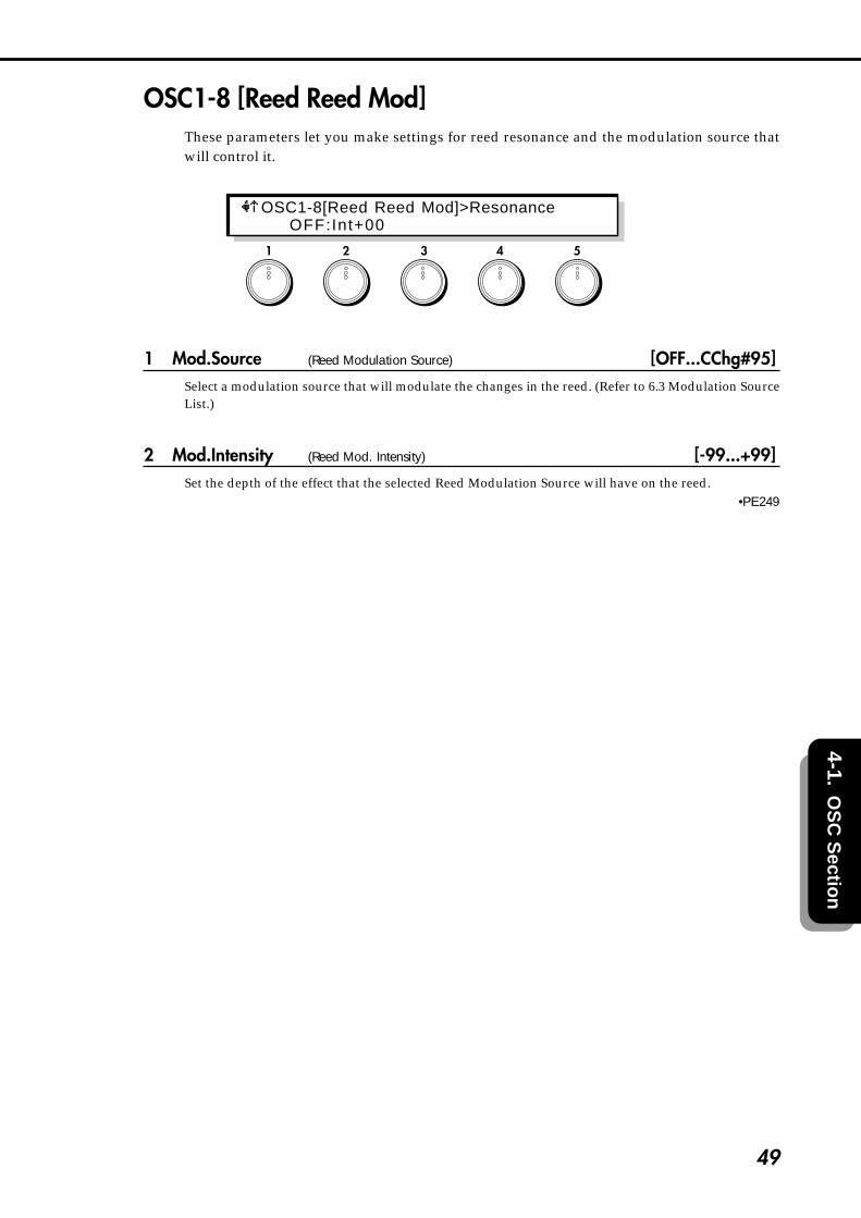
49
4-1.O
SC
Sectio
n
OSC1-8 [Reed Reed Mod]These parameters let you make settings for reed resonance and the modulation source thatwill control it.
1 Mod.Source (Reed Modulation Source) [OFF...CChg#95]Select a modulation source that will modulate the changes in the reed. (Refer to 6.3 Modulation SourceList.)
2 Mod.Intensity (Reed Mod. Intensity) [-99...+99]Set the depth of the effect that the selected Reed Modulation Source will have on the reed.
•PE249
1 2 3 4 5
OSC1-8[Reed Reed Mod]>Resonance OFF:Int+00
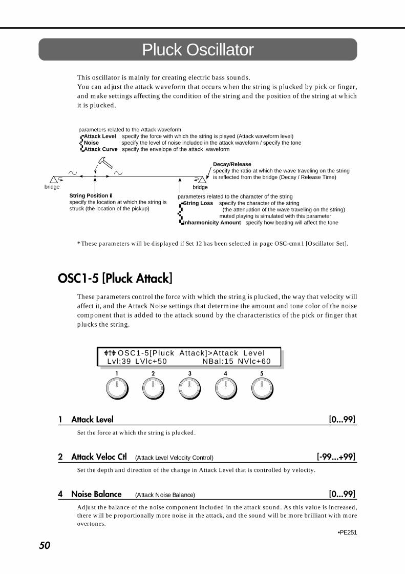
50
Pluck OscillatorThis oscillator is mainly for creating electric bass sounds.You can adjust the attack waveform that occurs when the string is plucked by pick or finger,and make settings affecting the condition of the string and the position of the string at whichit is plucked.
String Position�specify the location at which the string is struck (the location of the pickup)
Attack Level specify the force with which the string is played (Attack waveform level)Noise specify the level of noise included in the attack waveform / specify the toneAttack Curve specify the envelope of the attack waveform
Decay/Releasespecify the ratio at which the wave traveling on the string is reflected from the bridge (Decay / Release Time)
bridge bridge
parameters related to the Attack waveform
{
String Loss specify the character of the string (the attenuation of the wave traveling on the string)
muted playing is simulated with this parameterInharmonicity Amount specify how beating will affect the tone
parameters related to the character of the string
{* These parameters will be displayed if Set 12 has been selected in page OSC-cmn1 [Oscillator Set].
OSC1-5 [Pluck Attack]These parameters control the force with which the string is plucked, the way that velocity willaffect it, and the Attack Noise settings that determine the amount and tone color of the noisecomponent that is added to the attack sound by the characteristics of the pick or finger thatplucks the string.
1 Attack Level [0...99]Set the force at which the string is plucked.
2 Attack Veloc Ctl (Attack Level Velocity Control) [-99...+99]Set the depth and direction of the change in Attack Level that is controlled by velocity.
4 Noise Balance (Attack Noise Balance) [0...99]Adjust the balance of the noise component included in the attack sound. As this value is increased,there will be proportionally more noise in the attack, and the sound will be more brilliant with moreovertones.
•PE251
1 2 3 4 5
OSC1-5[Pluck At tack]>At tack Level Lvl:39 LVlc+50 NBal:15 NVlc+60

51
4-1.O
SC
Sectio
n
5 Noise Lvl VelCtl (Attack Noise Level Velocity Control) [-99...+99]Specify the depth and direction of the effect that velocity will have on the level of noise that is includedin the attack.
OSC1-6 [Pluck Noise Filter]These parameters determine the tone color of the noise component included in the attack,simulating the characteristics of the pick or finger that plucks the string.
1 Type (Attack Noise Filter Type) [LPF, HPF, BPF]Select the type of filter that will process the attack noise; LPF (low pass filter), HPF (high pass filter), orBPF (band pass filter). For details on the various types of filter, refer to Filter Section page FL1-1 [Type& Input].
2 Fc (Attack Noise Filter Fc) [0...99]Set the cutoff frequency at which the filter will process the attack noise.
•PE252
3 Fc Vel Ctl (Attack Noise Filter Fc Velocity Control) [-99...+99]Set the depth and direction with which velocity will affect the Attack Noise Filter Fc (frequency).
4 Resonance (Attack Noise Filter Resonance) [0...99]Set the degree to which the frequency range in the area of the Attack Noise Filter Fc setting will beemphasized.
1 2 3 4 5
OSC1-6[Pluck Noise Fi l ter ]>Type LPF Fc:00 Vlc-99 Reso:00
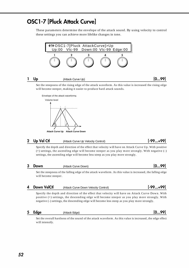
52
OSC1-7 [Pluck Attack Curve]These parameters determine the envelope of the attack sound. By using velocity to controlthese settings you can achieve more lifelike changes in tone.
1 Up (Attack Curve Up) [0...99]Set the steepness of the rising edge of the attack waveform. As this value is increased the rising edgewill become steeper, making it easier to produce hard attack sounds.
Envelope of the attack waveform
Attack Curve Up Attack Curve Down
Volume level
2 Up Vel Ctl (Attack Curve Up Velocity Control) [-99...+99]Specify the depth and direction of the effect that velocity will have on Attack Curve Up. With positive(+) settings, the ascending edge will become steeper as you play more strongly. With negative (–)settings, the ascending edge will become less steep as you play more strongly.
3 Down (Attack Curve Down) [0...99]Set the steepness of the falling edge of the attack waveform. As this value is increased, the falling edgewill become steeper.
4 Down VelCtl (Attack Curve Down Velocity Control) [-99...+99]Specify the depth and direction of the effect that velocity will have on Attack Curve Down. Withpositive (+) settings, the descending edge will become steeper as you play more strongly. Withnegative (–) settings, the descending edge will become less steep as you play more strongly.
5 Edge (Attack Edge) [0...99]Set the overall hardness of the sound of the attack waveform. As this value is increased, the edge effectwill intensify.
1 2 3 4 5
OSC1-7[Pluck AttackCurve]>Up Up:00 Vlc-99 Down:00 Vlc-99 Edge:00
Volume level
Envelope of the attack waveform

53
4-1.O
SC
Sectio
n
OSC1-8 [Pluck String Position]These parameters set the position at which the string is plucked.
1 Position (String Position) [0...99]Set the location at which the string is plucked and the location of the pickup. Increasing this value willsimulate a pluck closer to the bridge.
•PE253
2 Vel Ctrl (String Position Velocity Control) [-99...+99]Set the depth and direction of the effect that velocity will have on String Position.
3 Mod.Src (String Position Modulation Source) [OFF...CChg#95]Select the modulation source that will control String Position. (Refer to 6.3 Modulation Source List.)
4 Mod.Int (String Position Modulation Intensity) [-99...+99]Set the depth and direction of the effect that the selected String Position Mod.Source will have on StringPosition. With positive (+) settings, higher values of the modulation source will increase the StringPosition value. With negative (–) settings, lower values of the modulation source will increase theString Position value. If EG or LFO has been selected as the String Position Modulation Source, positive(+) settings will cause the original phase of the EG or LFO to be used, and negative (–) settings willinvert the phase.
1 2 3 4 5
OSC1-8 [P luck S t r ingPos i t i on ]>Pos i t i onPosi:00 PVlc+20 OFF:Int+00

54
1 2 3 4 5
OSC1-9 [Pluck String Loss]These parameters affect the way in which the string vibrates.
1 String Loss [0...99]The setting of this parameter determines how vibration will pass through the string, and how highfrequency components will be attenuated by the bridge and finger (pressing the string), etc. As thisvalue is increased, the high frequencies will be attenuated more heavily, making the tone darker.Conversely, as this value is lowered, there will be less attenuation of the high frequency components,producing a brighter tone.
•PE254
2 Kbd Track (String Loss Keyboard Tracking) [-99...+99]Specify how keyboard position will affect String Loss. With positive (+) settings, playing above the C4key will progressively increase the String Loss. With negative (–) settings, playing above the C4 keywill progressively decrease the String Loss.
C-1 C4 C9
99
0
50
C-1 C4 C9
99
0
75
C-1 C4 C9
99
0
25
+99 +50
0
-99 -50
+99 +50
0
-50
-99
+99
+50
-50
-99
0
String Loss String Loss String Loss
when String Loss = 50 when String Loss = 75 when String Loss = 25
3 Mod.Source (String Loss Modulation Source) [OFF...CChg#95]Select the modulation source that will control String Loss. (Refer to 6.3 Modulation Source List.)
4 Mod.Int (String Loss Modulation Intensity) [-99...+99]Specify the depth and direction of the effect that the selected String Loss Modulation Source will have.With positive (+) settings, higher values of the modulation source will increase the String Loss value.With negative (–) settings, lower values of the modulation source will increase the String Loss value. IfEG or LFO has been selected as the String Loss Modulation Source, positive (+) settings will cause theoriginal phase of the EG or LFO to be used, and negative (–) settings will invert the phase.
OSC1-9[Pluck Str ing Loss]>Str ing LossLoss:10 KTr-99 OFF:Int+00
when String Loss = 50 when String Loss = 75 when String Loss = 25

55
4-1.O
SC
Sectio
n
OSC1-10 [Pluck Inharmonicity]These parameters affect the beating of the string.
1 Amount (Inharmonicity Amount) [0...99]Specify the amount of inharmonicity. As this value is increased, the string will beat more deeply.
•PE255
Some String Loss and Inharmonicity Amount settings may cause the pitch to deviate from thestandard pitch. In such cases, use the respective keyboard tracking parameters to compensatefor the pitch deviation, or initialize the settings to Initial Source (page OSCU-2) #32:Plucked, andedit the sound once again.
2 KbdTrack (Inharmonicity Keyboard Tracking) [-99...+99]Specify how Inharmonicity Amount will be adjusted according to the keyboard position of the note.For positive (+) settings, the Inharmonicity Amount value will be increased for notes above C4. Fornegative (–) settings, the Inharmonicity value will be decreased for notes above C4.
C-1 C4 C9
99
0
50
C-1 C4 C9
99
0
75
C-1 C4 C9
99
0
25
+99 +50
0
-99 -50
+99 +50
0
-50
-99
+99
+50
-50
-99
0
Inharmonicity Amout
when Inharmonicity Amount = 50 when Inharmonicity Amount = 75 when Inharmonicity Amount = 25
Inharmonicity Amout Inharmonicity Amout
1 2 3 4 5
OSC1-10[Pluck Inharmonici ty]>AmountAmount:72 KTr-50
when Inharmonicity Amount = 75when Inharmonicity Amount = 50 when Inharmonicity Amount = 25

56
1 2 3 4 5
OSC1-11[Pluck Decay&Release]>Decay Dcy:92 KTr-01 Rlsa:83 KTr-50
OSC1-11 [Pluck Decay & Release]These parameters determine the Decay Time over which the sound decays while youcontinue holding a note, and the Release Time over which the sound will disappear when yourelease a note. You can also specify how keyboard position will affect these parameters.
1 Decay [0...99]Specify the Decay Time over which the sound will decay while you continue holding a note. Highersettings will produce a longer decay time.
Depending on the settings of the Amplitude Modulation EG (page Amp 1-2,1 / Amp 2-2,1), thisRelease setting may have no effect. If the Break Level and Sustain Level of the EG are raised, theeffect of this setting will be easier to hear.
2 DcyKbdTrk (Decay Keyboard Tracking) [-99...+99]Specify how keyboard position will affect the Decay Time. Positive (+) settings will slow down thedecay as you play above the C4 key, and negative (–) settings will speed up the decay.
C-1 C4 C9
99
0
50
C-1 C4 C9
99
0
75
C-1 C4 C9
99
0
25
-99 -50
0
+99 +50
-99 -50
0
+50
+99
-99
-50
+50
+99
0
Decay
When Decay=50 When Decay=75 When Decay=25
Decay Decay
4 Release [0...99]Specify the Release Time over which the sound will disapear when you release a note. Higher settingswill produce longer release times.
Depending on the settings of the Amplitude Modulation EG (page Amp 1-2,1 / Amp 2-2,1), thisRelease setting may have no effect. Setting the EG Release Time to a longer value will allow theeffect of this Release setting to be more apparent.
5 RlsKbdTrk (Release Keyboard Tracking) [-99...+99]Specify how keyboard position will affect the Release. Positive (+) settings will slow down the releaseas you play above the C4 key, and negative (–) settings will speed up the release.
C-1 C4 C9
99
0
50
C-1 C4 C9
99
0
75
C-1 C4 C9
99
0
25
-99 -50
0
+99 +50
-99 -50
0
+50
+99
-99
-50
+50
+99
0
Release
When Release=50 When Release=75 When Release=25
Release Release
when Release = 50 when Release = 75 when Release = 25
when Decay = 75 when Decay = 25when Decay = 50
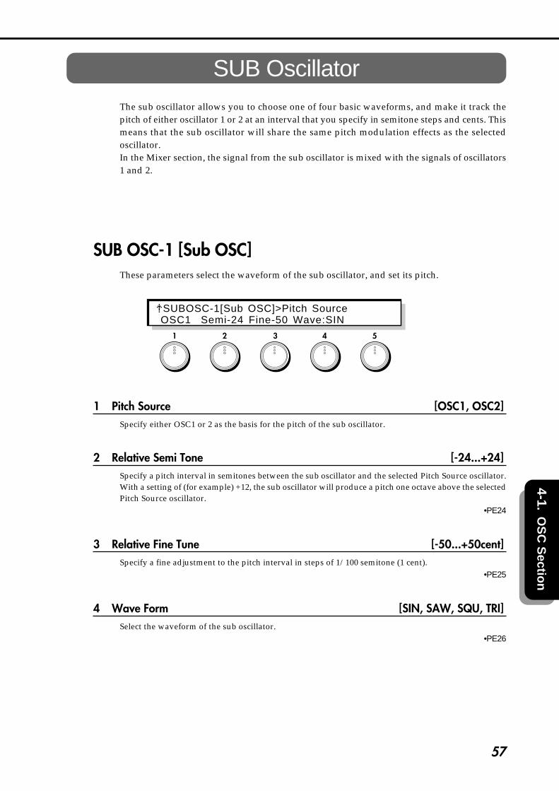
57
4-1.O
SC
Sectio
n
SUB OscillatorThe sub oscillator allows you to choose one of four basic waveforms, and make it track thepitch of either oscillator 1 or 2 at an interval that you specify in semitone steps and cents. Thismeans that the sub oscillator will share the same pitch modulation effects as the selectedoscillator.In the Mixer section, the signal from the sub oscillator is mixed with the signals of oscillators1 and 2.
SUB OSC-1 [Sub OSC]These parameters select the waveform of the sub oscillator, and set its pitch.
1 Pitch Source [OSC1, OSC2]Specify either OSC1 or 2 as the basis for the pitch of the sub oscillator.
2 Relative Semi Tone [-24...+24]Specify a pitch interval in semitones between the sub oscillator and the selected Pitch Source oscillator.With a setting of (for example) +12, the sub oscillator will produce a pitch one octave above the selectedPitch Source oscillator.
•PE24
3 Relative Fine Tune [-50...+50cent]Specify a fine adjustment to the pitch interval in steps of 1/100 semitone (1 cent).
•PE25
4 Wave Form [SIN, SAW, SQU, TRI]Select the waveform of the sub oscillator.
•PE26
1 2 3 4 5
SUBOSC-1[Sub OSC]>Pitch Source OSC1 Semi-24 Fine-50 Wave:SIN
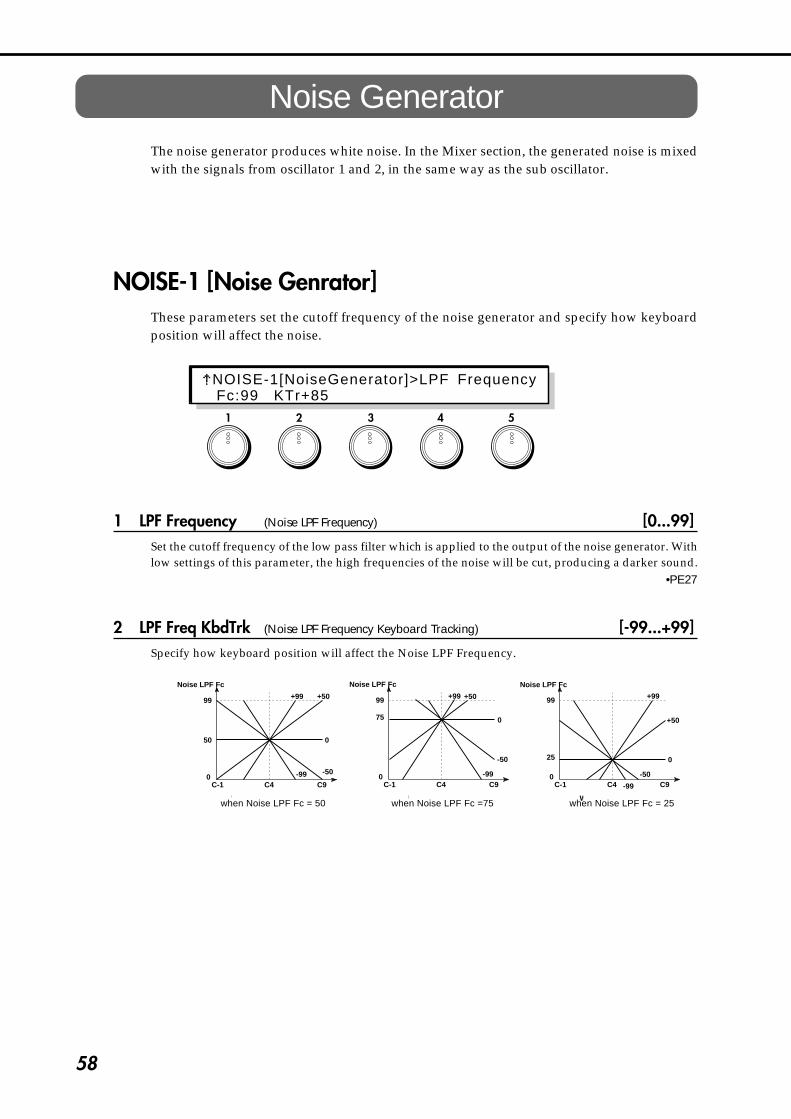
58
Noise GeneratorThe noise generator produces white noise. In the Mixer section, the generated noise is mixedwith the signals from oscillator 1 and 2, in the same way as the sub oscillator.
NOISE-1 [Noise Genrator]These parameters set the cutoff frequency of the noise generator and specify how keyboardposition will affect the noise.
1 LPF Frequency (Noise LPF Frequency) [0...99]Set the cutoff frequency of the low pass filter which is applied to the output of the noise generator. Withlow settings of this parameter, the high frequencies of the noise will be cut, producing a darker sound.
•PE27
2 LPF Freq KbdTrk (Noise LPF Frequency Keyboard Tracking) [-99...+99]Specify how keyboard position will affect the Noise LPF Frequency.
C-1 C4 C9
Noise LPF Fc
99
0
50
C-1 C4 C9
99
0
75
C-1 C4 C9
99
0
25
+99 +50
0
-99 -50
+99 +50
0
-50
-99
+99
+50
-50
-99
0
Noise LPF Fc Noise LPF Fc
When Noise LPF Fc=50 When Noise LPF Fc=75 When Noise LPF Fc=25
1 2 3 4 5
NOISE-1[NoiseGenerator]>LPF Frequency Fc:99 KTr+85
when Noise LPF Fc = 50 when Noise LPF Fc =75 when Noise LPF Fc = 25

59
4-1.O
SC
Sectio
n
1 2 3 4 5
[ UTY ] - Utility
OSCU-1 [Initialize]This command initializes the oscillator.
1 OSC Select (Oscilator select) [OSC1, OSC2, ALL ]The oscillator will be initialized to a setting that is appropriate for the currently selected oscillator type(including Modulation and Inst types). Use this command if the oscillator is no longer soundingproperly, or if you wish to start over with your editing with the currently selected oscillator type.If you select OSC1, settings of pages OSC1-5 and following for the oscillator currently selected as OSC1will be initialized. If you select OSC2, settings of pages OSC2-5 and following for the oscillatorcurrently selected as OSC2 will be initialized. If you select ALL, all of the above settings (OSC1 andOSC2) settings will be initialized.
After selecting the data to be initialized, press the ENTER key to execute.
OSCU-2 [Set Initialize]This command initializes a specified oscillator set.
1 Initial Type [#00...32]This command initializes the oscillator set to a basic setting appropriate for the selected type. Executethis command when you change the oscillator type.
Make the desired selection, and press the ENTER key to execute.
1 2 3 4 5
OSCU-1[ In i t ia l i ze ]>OSC Selec t OSC1 XXX<Press ENTER >
O S C U - 2 [ S e t I n i t i a l i z e ] > I n i t i a l T y p e#00:Std+Std <Press ENTER >

60
OSCU-3 [COPY]This command copies the specified block of OSC section settings from another program to the currentlyselected program.
1 Source Program [A00...C63]Specify the program number for the copy source.If you have selected C00~C63 and if no card is inserted, the display will indicate <No Card>, and theoperation will be halted. If an unformatted card is inserted, the display will indicate <Illegal Format>,and the operation will be halted.
2 Target Block [OSCcmn, OSC1, OSC2 , SubOSC, NOISE, ALL]Specify the desired block of OSC section settings that you wish to copy.If you have selected OSC1 or OSC2 and if the copy source and the current oscillator types are different,the display will indicate <OSC Type Error>, and the operation will be halted.If you select ALL, the Oscillator Set selection will also be copied.
Make the desired selection, and press the ENTER key to execute.
This page is the last page except for Oscillator Sets 1, 5, and 8.
OSCU-4 [Duplicate]This command sets oscillators 1 and 2 of the current program to the identical settings.
1 (Duplicate Source) [(OSC1 --> OSC2), (OSC2 --> OSC1)For Oscillator Sets 1, 5, and 8, you can set OSC1 and OSC2 to the identical settings. Select the oscillator(at the left) whose settings will be duplicated.
Make the desired selection, and press the ENTER key to execute.
1 2 3 4 5
1 2 3 4 5
OSCU-4[Duplicate] OSC1 OSC2 <Press ENTER >
OSCU-3[Copy]>Source Program A00 OSCcmn <Press ENTER >

61
4-1.O
SC
Sectio
n
OSCU-5 [Swap]This command exchanges the settings of oscillators 1 and 2 within the current program.
For Oscillator Sets 1, 5, and 8, you can exchange the settings of oscillator 1 and 2.
Press the ENTER key to execute.
1 2 3 4 5
OSCU-4[Swap] OSC1 OSC2 <Press ENTER >

62
1 2 3 4 5
4-2. Wave Shape SectionTwo independent wave shaping tables are provided, one for each oscillator 1 and 2. Thesemodify the waveform to create elements not originally present, such as resonant or distortedsounds.
The following diagram shows the signal flow in the wave shaping section.
Osc1
Osc2
Offset
Offset Cross Loop Level
Feedback Level
Cross Loop Level
Feedback Level
WS1 Table
WS2 Table
Thru Gain
Output Gain
Thru Gain
Output Gain
Input Gain
Input Gain
Wave Shape 1Block
Wave Shape2Block
to Mixer Block
to Mixer Block
WS-1 [WaveShap Menu]This is the wave shape menu page.
1 [ WS1 ] (Wave Shape 1)
2 [ WS2 ] (Wave Shape 2)
5 [ UTY ] (Utility)
Select the wave shaping table that you wish to edit, or the wave shaping utilities.[WS1] and [WS2] make settings for each wave shaping table. [UTY] lets you initialize, copy, andexchange wave shaping table data.Use the CURSOR keys or the knobs to select the item that you wish to edit, and press the ENTER key toenter the item.The parameters for [WS2] are identical to those of [WS1]. Refer to the explanations for WS1-1…5.
WS-1[WaveShape Menu](Turn & Press ENTER) WS1 [ WS2 ] [ UTY ]

63
4-2. Wave Shape Section
1 2 3 4 5
[ WS1 ]WS1-1 [Input Gain]
These parameters set the level of the signal from OSC1 that is input to the Wave Shapesection, and specify the modulation source etc. that will control the input gain.
1 Gain (Input Gain) [0...99]Set the level of the signal that is input from OSC1 to the Wave Shape section.
•PE169 : WS1 •PE176 : WS2
2 Mod.Source (Input Gain Modulation Source) [OFF...CChg#95]Select the modulation source that will control the Input Gain. (Refer to 6.3 Modulation Source List.)
3 Mod.Intensity (Input Gain Mod.Intensity) [-99...+99]Set the depth and direction in which the selected Input Gain Modulation Source will affect the InputGain. With positive (+) settings, higher values of the modulation source will increase the Input Gain.With negative (-) settings, lower values of the modulation source will increase the Input Gain. If EG orLFO has been selected as the Input Gain Modulation Source, positive (+) settings will cause the originalphase of the EG or LFO to be used, and negative (-) settings will invert the phase.
•PE170 : WS1 •PE177 : WS2
出力レベル�
入力レベル�Input Gain=99 Input Gain=75 Input Gain=50 Input Gain=25
入力波形�
出力波形�
Input Gain を変化させた時の例�(Table Type : Reso)
WS1-1[Input Gain]>GainGain:00 OFF:Int-99
An example of changing the Input Gain (Table Type: Reso)
Output level
Input level
Input waveform
Output waveform

64
WS1-2 [Input Offset]This parameter lets you specify an offset value that will be added to the level of the signal thatis input from Input Gain.
1 Input Offset [-99...+99]Specify the offset amount that will added to the signal specified by Input Gain (page WS1-1,1).
Output level
Input level
Input waveform (Input Gain fixed)
Output waveform
An example of changing the Offset (Table Type: Clip)
Offset=50 Offset=0 Offset=-50
By using Input Gain to reduce the input signal level and adding an Input Offset, you can bias the waveshaping table.
1 2 3 4 5
Output level
Input level
Input waveform (Input Gain fixed)
WS1-2[ Inpu t Of fse t ]O f s t : 0 0
An example of changing the Offset (Table Type: Clip)
Output waveform

65
4-2. Wave Shape Section
WS1-3 [Feedback & Cross Loop]These parameters determine the amount of the wave shaping 1 output that is fed back, andthe amount of the wave shaping 2 output that is added to the input of wave shape 1.
2 Feedback Level [0...99]Set the amount of waveshape 1 output that is fed back.
4 Cross Loop Level [0...99]Set the amount of the wave shape 2 output that is added to the input of wave shape 1.
Some settings of Feedback Level and Cross Loop Level may produce distorted sound or nosound at all. In such cases, reduce the levels.
WS1-4 [Wave Shape]Select the wave shaping table that will modify the input waveform, and specify a modulationsource that will control the characteristics of the table.
1 Table Select (Shape Table Type) [CLIP, RESO]Select the wave shaping table that will modify the input waveform. The two table types CLIP (Clip type)and RESO (Resonant type) will produce the effects shown in the diagrams below.
•PE171 : WS1 •PE178 : WS2
1 2 3 4 5
1 2 3 4 5
WS1-3[Fback & XLoop]>Feedback Level Feedback:00 CrossLoop:00
WS1-4[Wave Shape]>Table SelectTb:CLIP Shp:00 OFF:Int-99

66
2 Shape [0...99]Set the characteristics of the table that modifies the input waveform. The diagrams below show howthis parameter modifies the table.
•PE172 : WS1 •PE179 : WS2
Output level
Input level
Wave Shaping Table and the Shape parameter
Clip type
Shape:0 Shape:99
Shape:0 Shape:99
Output level
Input level
Resonant type
Output of the Clip table with a sawtooth wave input
Output of the Resonant table with a sawtooth wave input
Waveform level
Waveform level
Waveform before entering the table
Waveform before entering the table
3 Mod.Source (Shape Modulation Source) [OFF...CChg#95]Select the modulation source that will control Shape. (Refer to 6.3 Modulation Source List.)
4 Mod.Intensity (Shape Mod.Intensity) [-99...+99]Set the depth and direction in which the selected Shape Modulation Source will affect the Shape. Withpositive (+) settings, higher values of the modulation source will increase the Shape value. Withnegative (-) settings, lower values of the modulation source will increase the Shape value. If EG or LFOhas been selected as the Shape Modulation Source, positive (+) settings will cause the original phase ofthe EG or LFO to be used, and negative (-) settings will invert the phase.
•PE173 : WS1 •PE180 : WS2
Wave Shaping Table and the Shape parameter
Output of the Clip table witha sawtooth wave input
Output level
Waveform level
Waveform before entering the table
Output of the Resonant table witha sawtooth wave input
Resonant typeOutput level
Clip type
Input levelWaveform level
Waveform before entering the table
Input level

67
4-2. Wave Shape Section
WS1-5 [Output]These parameters adjust the output levels of the sound that passes through Wave Shaping 1and the direct sound from OSC1.
2 Output Gain [0...99]Set the level of the output signal from Wave Shaping 1.
•PE174 : WS1 •PE181 : WS2
4 ThruGain (Thru Gain) [0...99]Set the level of the direct signal from OSC1.
•PE175 : WS1 •PE182 : WS2
出力レベル�
入力レベル�
入力波形�
(Table Type : Reso)
Thru Gain=70
Thru Gain / Output Gain を使用した時の例�
ウェーブシェープテーブル�の出力波形�(Output Gain=25)
[ WS2 ]WS2-1 [Input Gain]...WS2-5 [Output]
The [WS2] parameters are the same as the [WS1] parameters. [WS1-1…5]. Refer to the abovesections WS1-1…1-5.
1 2 3 4 5
Output level
Input level
Output waveform of the WaveShaping Table (Output Gain = 25)
Input waveform
WS1-5[Output]>Output Gain OutputGain:00 ThruGain:00
An example of using Thru Gain / Output Gain (Table Type: Reso)

68
1 2 3 4 5
[ UTY ] - Utility
WSU-1 [Initialize]This utility command initializes the wave shaping table.
1 WS Select (Wave Shape Select) [WS1, WS2, ALL]Select the wave shape that you wish to initialize.
2 Initial Type [#0...5]Select one of the following 6 recommended settings.
#0:Thru There will be no wave shaping effect.#1:Booster The signal will be boosted.#2:SoftClip The signal will be lightly clipped.#3:HardClip The signal will be heavily clipped.#4:SoftResonant Light resonance will be applied.#5:HardResonant Heavy resonance will be applied.
Make the desired selection, and press the ENTER key to execute.
WSU-2 [Copy]This utility command copies the wave shaping parameters of another program to thecurrently selected program.
1 Source Program [EDIT, A00...C63]Select the copy source program.If you have selected C00~C63 and if no card is inserted, the display will indicate <No Card>, and theoperation will be halted. If an unformatted card is inserted, the display will indicate <Illegal Format>,and the operation will be halted.
1 2 3 4 5
WSU-2[Copy]>Source Program EDIT: WS1 WS1 <Press ENTER >
WSU-1[ In i t ia l i ze ]>WS Se lec t WS1 #0:Thru <Press ENTER >

69
4-2. Wave Shape Section
2 Source WS (Source Wave Shape) [WS1, WS2, ALL]Select the copy source wave shape. If ALL is selected, the following Destination setting will be ignored.
3 Destination [WS1, WS2]Select the copy destination (current) wave shape.
Make the desired selection, and press the ENTER key to execute.
If the Source Program is EDIT and if the Source WS and the Destination are the same, the displaywill indicate <Ignore > and the operation will be halted.
WSU-3 [Swap]This utility command exchanges the settings of wave shape 1 and 2 within the same program.
Press the ENTER key to execute.
1 2 3 4 5
WSU-3[Swap] WS1 WS2 <Press ENTER >
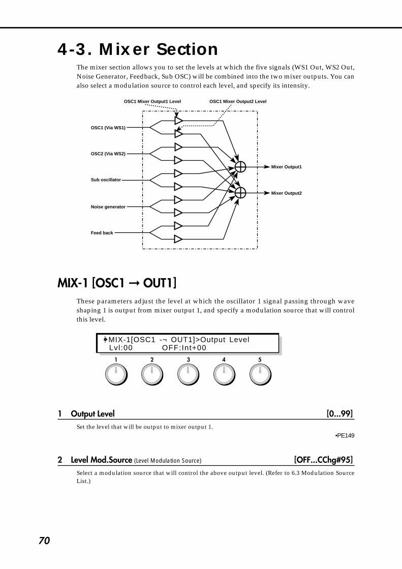
70
4-3. Mixer SectionThe mixer section allows you to set the levels at which the five signals (WS1 Out, WS2 Out,Noise Generator, Feedback, Sub OSC) will be combined into the two mixer outputs. You canalso select a modulation source to control each level, and specify its intensity.
OSC1 (Via WS1)
OSC1 Mixer Output1 Level
Mixer Output1
Mixer Output2
OSC1 Mixer Output2 Level
OSC2 (Via WS2)
Sub oscillator
Noise generator
Feed back
MIX-1 [OSC1 � OUT1]These parameters adjust the level at which the oscillator 1 signal passing through waveshaping 1 is output from mixer output 1, and specify a modulation source that will controlthis level.
1 Output Level [0...99]Set the level that will be output to mixer output 1.
•PE149
2 Level Mod.Source (Level Modulation Source) [OFF...CChg#95]Select a modulation source that will control the above output level. (Refer to 6.3 Modulation SourceList.)
1 2 3 4 5
MIX-1[OSC1 -¬ OUT1]>Output Level Lvl:00 OFF:Int+00

71
4-3. Mixer S
ection
3 Level Mod.Int (Level Mod.Intensity) [–99...+99]Set the depth and direction in which the selected Level Modulation Source will affect the level. Withpositive (+) settings, higher values of the modulation source will increase the level. With negative (-)settings, lower values of the modulation source will increase the level. If EG or LFO has been selected asthe Level Modulation Source, positive (+) settings will cause the original phase of the EG or LFO to beused, and negative (-) settings will invert the phase.
•PE150
MIX-2 [OSC1 � OUT2]These parameters adjust the level at which the oscillator 1 signal passing through waveshaping 1 is output from mixer output 2, and specify a modulation source that will controlthis level.Refer to the above explanation of MIX-1 [OSC1 → OUT1]
•PE151: Level •PE152: Level Mod. Intensity
MIX-3 [OSC2 � OUT1]These parameters adjust the level at which the oscillator 2 signal passing through waveshaping 2 is output from mixer output 1, and specify a modulation source that will controlthis level.Refer to the above explanation of MIX-1 [OSC1 → OUT1].
•PE153: Level •PE154: Level Mod. Intensity
MIX-4 [OSC2 � OUT2]These parameters adjust the level at which the oscillator 2 signal passing through waveshaping 2 is output from mixer output 2, and specify a modulation source that will controlthis level.Refer to the above explanation of MIX-1 [OSC1 → OUT1].
•PE155: Level •PE156: Level Mod. Intensity
MIX-5 [SUBOSC � OUT1]These parameters adjust the level at which the sub oscillator signal output is output frommixer output 1, and specify a modulation source that will control this level.Refer to the above explanation of MIX-1 [OSC1 → OUT1].
•PE157: Level •PE158: Level Mod. Intensity
MIX-6 [SUBOSC � OUT2]These parameters adjust the level at which the sub oscillator signal output is output frommixer output 2, and specify a modulation source that will control this level.Refer to the above explanation of MIX-1 [OSC1→ OUT1].
•PE159: Level •PE160: Level Mod. Intensity
72
MIX-7 [NOISE � OUT1]These parameters adjust the level at which the output of the noise generator is output frommixer output 1, and specify a modulation source that will control this level.Refer to the above explanation of MIX-1 [OSC1 → OUT1].
•PE161: Level •PE162: Level Mod. Intensity
MIX-8 [NOISE � OUT2]These parameters adjust the level at which the output of the noise generator is output frommixer output 2, and specify a modulation source that will control this level.Refer to the above explanation of MIX-1 [OSC1 → OUT1].
•PE163: Level •PE164: Level Mod. Intensity
MIX-9 [Feedback � OUT1]These parameters adjust the level at which the feedback from the amp section is output frommixer output 1, and specify a modulation source that will control this level.Refer to the above explanation of MIX-1 [OSC1 → OUT1].
•PE165: Level •PE166: Level Mod. Intensity
MIX-10 [Feedback � OUT2]These parameters adjust the level at which the feedback from the amp section is output frommixer output 2, and specify a modulation source that will control this level.Refer to the above explanation of MIX-1 [OSC1 → OUT1].
•PE167: Level •PE168: Level Mod. Intensity
Raising the Feedback level excessively may cause the sound to distort.

73
4-4. Filter Section
4-4. Filter SectionThe Prophecy contains two multi-mode filters. For each one, you can select one of four filtertypes; LPF, HPF, BPF, and BRF.
FLT-1 [Filter Menu]Here you can select the routing type and access the items of the filter menu.
2 Routing (Filter Routing) [SERIAL1, SERIAL2, PARALLEL]Select one of three types of routing to specify how the output from the mixer will be pass through thefilters to the amplitude blocks.
Serial1
Serial2
Parallel
Mixer Output1
Mixer Output2
Filter1 Filter2 Amp1
Amp2
Mixer Output1
Mixer Output2
Filter1 Filter2 Amp1
Amp2
Mixer Output1
Mixer Output2
Filter1
Filter2
Amp1
Amp2
If you wish to use band pass filters to create two peaks in the frequency response, select PARALLEL.If you wish to use band reject filters to create two valleys in the frequency response, select SERIAL. Inthis case, setting filters 1 and 2 to the same settings will sharpen the slope of the cutoff.
Multimode Filter
Input TrimCutoff Frequency data
Filter Block
Resonance data
Filter Mode Selector
LPFHPFBPFBRF
Thru
1 2 3 4 5
FLT-1[Fi l ter Menu] (Turn & Press ENTER) Route:SELIAL1 FILTR1 [FILTR2] [ UTY ]

74
3 [FILTR1] (Filter1)
4 [FILTR2] (Filter2)
5 [UTY] (Utility)
3, 4, and 5 are menu items. Select filter 1 or 2 for editing, or select the utility commands. [FILTR1]and [FILTR2] are the settings for the two filters. [UTY] allows you to initialize or copy filtersettings. Use the CURSOR keys or the knobs to select the desired item, and press the ENTER key toenter the selected page.The parameters of [FILT2] are organized in the same way as those of FILTR1. Refer to the explanationsfor page FL1-1…5.
FL1-1 [Type & Input]These parameters specify the filter type for filter 1, and set the level of the signal input fromthe mixer.
2 Filter Type [THRU, LPF, HPF, BPF, BRF]Select the filter type for filter 1.
フィルタタイプとカットオフ周波数について�
LPFはカットオフ周波数よりも上の�帯域をカットするフィルタです。�(Low Pass Filter)
THRU (Thrugh)ではフィルタがかかりません。�
周波数�
LPF
周波数�
HPF
BPF
BRF
周波数�
周波数�
HPFはカットオフ周波数よりも下の�帯域をカットするフィルタです。�(High Pass Filter)��
BPFはカットオフ周波数近辺以外の�帯域をカットするフィルタです。�(Band Pass Filter)
BRFはカットオフ周波数近辺のみを�カットするフィルタです。�(Band Reject Filter)��
カットオフ周波数�
カットオフ周波数�
カットオフ周波数�
カットオフ周波数�
How Filter Type is related to Cutoff Frequency
With a setting of THRU, the filter will not apply.
The LPF (low pass filter) cutsthe area above the cutofffrequency.
FrequencyCutoff frequency
Frequency
The BPF (band pass filter)cuts the areas above andbelow the cutoff frequency.
Cutoff frequency
Frequency
The BRF (band reject filter)cuts only the area of thecutoff frequency.
Cutoff frequencyFrequency
The HPF (high pass filter)cuts the area below thecutoff frequency.
Cutoff frequency
1 2 3 4 5
FL1-1[Type & Input ]>Fi l te r TypeFi l terType:THRU InputTr im:00

75
4-4. Filter Section
4 Input Trim [00...99]Adjust the level that is input to filter 1.
If this setting is increased, distortion may occur if the Resonance setting is high. To adjust thevolume, make settings in the AMP section page AMP1-1 and AMP2-1 AMPLITUDE.
FL1-2 [Cutoff]These parameters determine the cutoff frequency for filter 1, and how an EG will affect thecutoff frequency over time, etc.
1 Cutoff Frequency [00...99]Set the cutoff frequency for filter 1. Increasing this value will raise the cutoff frequency.
•PE28 : FL1 •PE34 : FL2
2 Mod.EG (Cutoff Frequency Modulation EG) [EG1...EG4, P.EG, A.EG]Specify the EG that will create time-varying change in the cutoff frequency of filter 1. For the settings ofeach EG, refer to p.111 for EG1~4, p.13 for the P.EG, and p.84 for the A.EG.
3 Mod.EG Intensity (Cutoff Frequency Mod. EG Int.) [-99...+99]Specify the depth and direction in which the Cutoff Frequency Modulation EG will affect the cutofffrequency. With positive (+) settings, the EG will move the Cutoff Frequency upward. (When thevarious EG levels are 0, the cutoff frequency will be at the value specified by the setting of the CutoffFrequency parameter.) The sound will become brighter for positive (+) EG levels, and darker (moremuted) for negative (-) EG levels.Setting negative (-) values for this Mod.EG Intensity parameter will have the opposite effect of positive(+) settings.
•PE29 : FL1 •PE35 : FL2
1 2 3 4 5
FL1-2 [Cuto f f ]>Cuto f f F requencyFc:00 EG1:Int+00

76
FL1-3 [Resonance]These parameters set the resonance of filter 1, and specify a modulation source which willcontrol the resonance.
1 Resonance [0...99]Specify the degree to which the frequencies in the region of the Cutoff Frequency (page FL1-2,1) will beemphasized. Higher values will produce a stronger effect. High settings of Resonance may cause theoutput signal of the filter to be distorted. In such cases, lower the Input Trim (FL1-1,4) setting.
•PE32 : FL1 •PE38 : FL2
レゾナンスによる効果�
LPF
HPF
BPF
BRF
レゾナンス値が小さい� レゾナンス値が大きい�
2 Mod.Source (Resonance Modulation Source) [OFF...CChg#95]Select the modulation source that will control Resonance. (Refer to 6.3 Modulation Source List.)
3 Mod.Intensity (Resonance Mod. Intensity) [-99...+99]Specify the amount and direction by which the selected Resonance Modulation Source will affect theResonance. With positive (+) settings the Resonance will be raised, and with negative (-) settings it willbe lowered. If EG or LFO is selected as the Resonance Modulation Source, they will take effect withtheir original phase for positive (+) settings, and with inverted phase for negative (-) settings.
•PE33 : FL1 •PE39 : FL2
The effect of Resonance
low Resonance value high Resonance value
1 2 3 4 5
FL1-3[Resonance]>ResonanceReso:00 OFF:Int-99

77
4-4. Filter Section
FL1-4 [Fc Kbd Trk] Cutoff Frequency Keyboard TrackThese parameters specify how keyboard tracking will affect the cutoff frequency of filter 1.
1 Low Key [C-1...G9]Specify the key at which Lower keyboard tracking will begin.
2 High Key [C-1...G9]Specify the key at which Higher keyboard tracking will begin.
3 Lower Intensity [-99...+99]Specify the depth and direction with which key position below the Low Key will affect the CutoffFrequency. With a setting of -50, the change in Cutoff Frequency will be the same as the change in pitch.
4 Higher Intensity [-99...+99]Specify the depth and direction with which key position above the High Key will affect the CutoffFrequency. With a setting of -50, the change in Cutoff Frequency will be the same as the change in pitch.
C-1 C4 C9
Int< 0
Int< 0
Int=-50 Int=-50
Int= 0
Int= 0
Int> 0
Int> 0
LowKey
HighKey
Cutofffrequency
With positive (+) settings, the sound will become brighter as you play further beyond the Low Key orHigh Key. Negative (-) settings will have the opposite effect. With a setting of 0, the cutoff frequencywill remain the same regardless of the position of the note you play. The cutoff frequency value in thearea between Low Key and High Key is fixed.
Cutofffrequency
1 2 3 4 5
FL1-4[Fc Kbd Trk]>Low KeyLK:C-1 HK:C-1 LInt-99 HInt-99
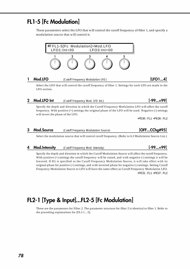
78
1 2 3 4 5
FL1-5 [Fc Modulation]These parameters select the LFO that will control the cutoff frequency of filter 1, and specify amodulation source that will control it.
1 Mod.LFO (Cutoff Frequency Modulation LFO) [LFO1...4]Select the LFO that will control the cutoff frequency of filter 1. Settings for each LFO are made in theLFO section.
2 Mod.LFO Int (Cutoff Frequency Mod. LFO Int.) [-99...+99]Specify the depth and direction in which the Cutoff Frequency Modulation LFO will affect the cutofffrequency. With positive (+) settings the original phase of the LFO will be used. Negative (-) settingswill invert the phase of the LFO.
•PE30 : FL1 •PE36 : FL2
3 Mod.Source (Cutoff Frequency Modulation Source) [OFF...CChg#95]Select the modulation source that will control cutoff frequency. (Refer to 6.3 Modulation Source List.)
4 Mod.Intensity (Cutoff Frequency Mod. Intensity) [-99...+99]Specify the depth and direction in which the Cutoff Modulation Source will affect the cutoff frequency.With positive (+) settings the cutoff frequency will be raised, and with negative (-) settings it will belowered. If EG is specified as the Cutoff Frequency Modulation Source, it will take effect with itsoriginal phase for positive (+) settings, and with inverted phase for negative (-) settings. Setting CutoffFrequency Modulation Source to LFO will have the same effect as Cutoff Frequency Modulation LFO.
•PE31 : FL1 •PE37 : FL2
FL2-1 [Type & Input]...FL2-5 [Fc Modulation]These are the parameters for Filter 2. The parameter structure for filter 2 is identical to filter 1. Refer tothe preceding explanations for [FL1-1…5].
FL1-5[Fc Modulation]>Mod.LFO LFO1:Int+00 LFO3:Int+00

79
4-4. Filter Section
[ UTY ] - Utility
FLU-1 [Initialize]This utility command initializes a filter.
1 Filter Select [Filter1, Filter2, Filter1&2]Select the filter that will be initialized.
2 Initial Type [#0...4]/[#0...3]The filter selected by Filter Select will be initialized to one of the following standard settings.
If Filter Select is Filter 1 or Filter 2:#0:Thru The filter will not be used.#1:LowPass Standard low pass filter settings.#2:HighPass Standard high pass filter settings.#3:BandPass Standard band pass filter settings.#4:BPF_Note Band pass filter settings where the center frequency will track the pitch.
If Filter Select is Filter 1&2:#0:SaxBody The filter will accentuate the characteristics of the Reed OSC.#1:Formant The filter will produce human voice-like tonality.#2:Trumpet The filter will accentuate the characteristics of the Brass OSC.#3:MuteTrumpet The filter will create the tone characteristic of a brass instrument with a mute
inserted.
Make settings, and press the ENTER key to execute.
1 2 3 4 5
F L U - 1 [ I n i t i a l i z e ] > F i l t e r S e l e c tFil ter1 #0:Thru <Press ENTER >

80
FLU-2 [Copy]This utility command copies filter settings from another program into the currently-selectedprogram.
1 Source Program [EDIT, A00...C63]Select the copy source program. If you select EDIT, the program currently being edited (i.e., theprogram in current memory) will be selected.If you have selected C00~C63 and if no card is inserted, the display will indicate <No Card>, and theoperation will be halted. If an unformatted card is inserted, the display will indicate <Illegal Format>,and the operation will be halted.
2 Source Filter [Filter1, Filter2, ALL]Select the copy source filter. If ALL is selected, the following Destination parameter will be ignored.
3 Destination [Filter1, Filter2]Select the copy destination filter.
Make selections, and press the ENTER key to execute.
If the Source Program is EDIT and the Source Filter and Destination are the same, the displaywill indicate <Ignore > and the operation will be halted.
FLU-3 [Swap]This utility command exchanges the filter 1 and 2 settings.
Press the ENTER key to execute.
1 2 3 4 5
1 2 3 4 5
FLU-2[Copy]>Source Program EDIT: Fi l ter1 Fi l ter1<Press ENTER >
FLU-3[Swap] Fi l ter1 Fi l ter2 <Press ENTER >

81
4-5. Am
plifier Section
1 2 3 4 5
4-5. Amplifier SectionThe amplifier (AMP) section contains the volume-related settings.There are two independent amplifiers, the signals which are input into the AMP section willdepend on the Filter Routing (page FLT-1,2).
AMP-1 [Amp Menu]This is the Amp Menu page.
1 [ AMP1 ] (Amplitude 1)
2 [ AMP2 ] (Amplitude 2)
3 [AMPEG] (Amplitude EG)
5 [ UTY ] (Utility)
Select the AMP or EG to edit, or the utility page.[AMP1] and [AMP2] make volume settings, and [AMPEG] determines how volume will change overtime. [UTY] allows you to initialize or copy amp-related settings.Use the CURSOR keys or the knobs to select the item that you wish to edit, and press the ENTER key toenter the item.The parameter structure of [AMP2] is the same as [AMP1]. Refer to the explanation of AMP1-1…2.
AMP-1[Amp Menu] (Turn & Press ENTER) AMP1 [ AMP2 ] [AMPEG] [ UTY ]

82
[ AMP1 ]AMP1-1 [Amplitude] - Amplitude 1
These parameters set the volume level of Amplitude 1, and specify the depth and direction bywhich volume levels will be adjusted by keyboard tracking.
1 Amplitude [0...99]Set the input levels of amp 1 from filter 1 and 2 (refer to page FLT-1,2). Higher values will produce ahigher volume level.
•PE40 : AMP1 •PE42 : AMP2
2 Kbd Trk Low Key (Keyboard Tracking Low Key) [C-1...G9]Specify the key at which Lower keyboard tracking will begin.
3 Kbd Trk High Key (Keyboard Tracking High Key) [C-1...G9]Specify the key at which Higher keyboard tracking will begin.
4 Kbd Trk Lower Int (Keyboard Tracking Lower Intensity) [-99...+99]Specify the depth and direction at which the volume level will be adjusted for notes lower than the Lowkey.
5 Kbd Trk Higher Int (Keyboard Tracking Higher Intensity) [-99...+99]Specify the depth and direction at which the volume level will be adjusted for notes above the Highkey.
C-1 C4 C9
Int=-50
Int= 0
Int> 0
Low Key
High Key
Int=0
Int=+50
Int=+99
Int<0
Int=-99
VolumeLevel
With positive (+) settings, the volume will be progressively increased for notes further away from theKeyboard Tracking Low/High Key. With negative (-) settings the opposite will occur. With a setting of0, the volume will be constant regardless of the position of the note. Notes between the Low Key andHigh Key will sound at the same volume.
1 2 3 4 5
AMP1-1[Ampl i tude]>Ampl i tudeAmp:99 LK:C-1 HK:C-1 LInt-99 HInt-99

83
4-5. Am
plifier Section
AMP1-2 [Amp Modulation]These parameters specify how a selected EG and modulation source will control amp 1.
1 Amp Mod.EG (Amplitude Modulation EG) [EG1...EG4, P.EG, A.EG]Select the EG that will apply time-variant changes to the Amplitude 1 volume level. For the settings ofeach EG, refer to p.111 for EG1~4, p.13 for the P.EG, and p.84 for the A.EG.
2 Mod.EG Int (Amplitude Mod. EG Intensity) [-99...+99]Specify the depth and direction of the effect that the selected Amplitude Modulation EG will have onthe volume.
3 Mod.Source (Amplitude Modulation Source) [OFF...CChg#95]Select a modulation source that will control the volume level of Amplitude 1. (Refer to 6.3 ModulationSource List.)
4 Mod.Intensity (Amplitude Mod. Intensity) [-99...+99]Specify the depth and direction of the effect that the Amplitude Modulation Source will have on thevolume. If you have selected EG or LFO as the Amplitude Modulation Source, positive (+) values willuse the original phase, and negative (–) values will invert the phase of the EG or LFO.
•PE41 : AMP1 •PE43 : AMP2
[ AMP2 ]AMP2-1 [Amplitude]...AMP2-2 [Amp Modulation]
These parameters are the settings for Amplitude 2. Amp 2 has the same parameter structure as amp 1.Refer to the preceding sections AMP1-1…2.
1 2 3 4 5
AMP1-2[Amp Modulation]>Amp Mod.EG A.EG:Int-99 OFF:Int-99

84
[AMP EG]Here you can make settings for the Amp EG. The Amp EG determines how the volume willchange over time.On the Prophecy, the Amp EG can be used as a general-purpose controller, so that it cancontrol time-varying changes for other parameters in addition to volume.
To create change in volume over time using the Amp EG, select A.EG for the AmplitudeModulation EG parameter (AMP1-2,1/AMP2-2,1), and set the Amplitude Mod.EG Intensityparameter (AMP1-2,2/AMP2-2,2) to specify the depth of the effect.You can have additional control over volume by selecting an Amplitude Modulation Source(AMP1-2,3/AMP2-2,3) and setting the Amplitude Mod.Intensity.
AEG-1 [Amp EG Level]These parameters specify the levels to which the volume will change in response to yourpressing and releasing a note.
Key offAttack level Sustain level
Key on
Attacktime
Decaytime
Slopetime
Releasetime
Time
Break point
Volume
How VDA1 creates time-varying changes in volume
1 Start Level [0...99]Set the volume level at key-on (when the note is pressed).
•PE44
2 Attack Level [0...99]Set the volume level reached after the Attack Time.
•PE46
3 Break Level [0...99]Set the volume level reached after the Decay Time.
•PE48
4 Sustain Level [0...99]Set the volume level reached after the Slope Time.
•PE50
Attack level Sustain levelKey off
Key on
Volume Breaklevel
How Amp EG creates time-varying changes in volume
1 2 3 4 5
Attacktime
Decaytime
Slopetime
Releasetime
Time
AEG-1[Amp EG Level ]>Start LevelStaL:00 AtkL:99 BrkL: 50 SusL:70

85
4-5. Am
plifier Section
AEG-2 [Amp EG Time]These parameters determine the times over which the volume will change in response to yourpressing and releasing a note.
2 Attack Time [0...99]Set the time over which the volume will change from key-on (when you press the key) until it reachesthe Attack Level. With a setting of 0, the volume will change instantly. With a setting of 99 it will changeslowly.
•PE45
3 Decay Time [0...99]Set the time over which the volume will change from after the Attack Time ends until the Break Point isreached. For details, refer to the preceding explanation of Attack Time.
•PE47
4 Slope Time [0...99]Set the time over which the volume will change from after the Decay Time ends until the Sustain Level isreached. For details, refer to the preceding explanation of Attack Time.
•PE49
5 Release Time [0...99]Set the time over which the volume will fall to zero after key-off (when you release the key). For details,refer to the preceding explanation of Attack Time.
•PE51
1 2 3 4 5
AEG-2[Amp EG Time]>Attack Time AtkT:30 DcyT:30 SlpT:10 RlsT:30

86
AEG-3 [Amp EG KbdTrk] Amplitude EG Keyboard Tracking
These parameters specify how keyboard position will affect the times of the Amplitude EG.
2 Attack Time [-99...+99]
3 Decay Time [-99...+99]
4 Slope Time [-99...+99]
5 Release Time [-99...+99]Specify the depth and direction at which each EG time (page AEG-2) will be affected by keyboardposition. With positive (+) settings, EG times will become longer as you play higher on the keyboard.With negative (-) settings, EG times will become shorter.
各タイムを-の値に設定した場合�
キー・オン�
キー・オフ�
キー・オン�
キー・オフ�
キー・オン�
キー・オフ�
Amp EGによる設定� 低い音程を弾いたとき� 高い音程を弾いたとき�
1 2 3 4 5
For negative (–) settings of the Time values:
when a low note is played when a high note is played
Key-on Key-on Key-on
Key-off Key-off Key-off
AEG-3[Amp EG KbdTrk]>Attack Time AtkT-99 DcyT-99 SlpT-99 RlsT-99
Amp EG settings
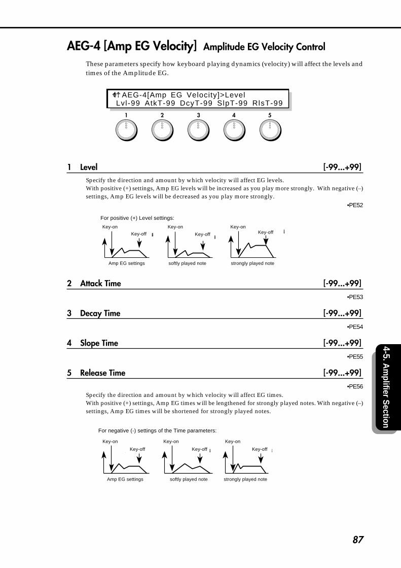
87
4-5. Am
plifier Section
AEG-4 [Amp EG Velocity] Amplitude EG Velocity Control
These parameters specify how keyboard playing dynamics (velocity) will affect the levels andtimes of the Amplitude EG.
1 Level [-99...+99]Specify the direction and amount by which velocity will affect EG levels.With positive (+) settings, Amp EG levels will be increased as you play more strongly. With negative (–)settings, Amp EG levels will be decreased as you play more strongly.
•PE52
Levelを+の値に設定した場合�
キー・オン�キー・オフ�
キー・オン�
キー・オフ�
キー・オン�
キー・オフ�
Amp EGによる設定� 弱く弾いたとき� 強く弾いたとき��
2 Attack Time [-99...+99]•PE53
3 Decay Time [-99...+99]•PE54
4 Slope Time [-99...+99]•PE55
5 Release Time [-99...+99]•PE56
Specify the direction and amount by which velocity will affect EG times.With positive (+) settings, Amp EG times will be lengthened for strongly played notes. With negative (–)settings, Amp EG times will be shortened for strongly played notes.
各タイムを-の値に設定した場合�
キー・オン�
キー・オフ�
キー・オン�
キー・オフ�
キー・オン�
キー・オフ�
Amp EGによる設定� 弱く弾いたとき� 強く弾いたとき�
1 2 3 4 5
For positive (+) Level settings:
Amp EG settings softly played note strongly played note
Key-on Key-on
Key-off Key-off Key-off
For negative (-) settings of the Time parameters:
Key-on Key-on Key-on
Key-off Key-off Key-off
AEG-4[Amp EG Velocity]>Level Lvl-99 AtkT-99 DcyT-99 SlpT-99 RlsT-99
Key-on
Amp EG settings softly played note strongly played note

88
[ UTY ] - Utility
AMPU-1 [Amp Copy]This utility command copies amplitude settings from a different program into the currentlyselected program.
1 Source Program [EDIT, A00...C63]Select the copy source program. If you select EDIT, the program currently being edited (the program incurrent memory) will be selected. If you have selected C00~C63 and if no card is inserted, the displaywill indicate <No Card>, and the operation will be halted.If an unformatted card is inserted, the display will indicate <Illegal Format>, and the operation will behalted.
2 Source Amp (Source Amplitude) [AMP1, AMP2, ALL]Select the copy source amplitude. If you select ALL, the following Destination parameter will beignored.
3 Destination (Target Amplitude) [AMP1, AMP2]Select the copy destination amplitude.
Make the desired selections, and press the ENTER key to execute.
If the Source Program is EDIT, and the same amp is selected for both Source Amp andDestination, the display will indicate <Ignore > and the operation will be halted.
AMPU-2 [Amp Swap]This utility command exchanges amplitude settings within the same program.
The AMP1 and AMP2 settings will be exchanged.
Press the ENTER key to execute.
1 2 3 4 5
1 2 3 4 5
AMPU-1[Amp Copy]>Source Program EDIT: AMP1 AMP1 <Press ENTER >
AMPU-2[Amp Swap] AMP1 AMP2 <Press ENTER >

89
4-5. Am
plifier Section
1 2 3 4 5
AMPU-3 [AmpEG Initialize]This utility command initializes Amplitude EG settings.
1 Initial Type [#00...10]Select one of the following 11 types of basic settings.
#00: Default#01: Piano#02: Bell#03: Guitar#04: Percussion#05: Organ#06: SoftAttack#07: SlowAttack#08: SoloString#09: Sweep#10: Pressure
Make the desired selection and press the ENTER key to execute.
AMPU-4 [AmpEG Copy]This utility command copies Amplitude EG settings from another program into the currentlyselected program.
1 Source Program [A00...C63]Select the copy source program.If you have selected C00~C63 and if no card is inserted, the display will indicate <No Card>, and theoperation will be halted. If an unformatted card is inserted, the display will indicate <Illegal Format>,and the operation will be halted.
Select the desired setting and press the ENTER key to execute.
1 2 3 4 5
AMPU-4[AmpEG Copy]>Source Program A00: AmpEG <Press ENTER >
AMPU-3[AmpEG In i t ia l ]> In i t ia l Type #00:Default <Press ENTER >

90
4-6. Effect SectionThe effect section provides seven types of effect, and two possible routings (ways in whichthe effects can be connected). The routing is selected by page FX-2 [Delay/Reverb] Delay/Reverb Select.
Distortion Wah Delay Chorus/Flanger Pan
Chorus&Delay
Reverb
PEQ
Distortion Wah PanPEQ Reverb
(Delay Reverb)GLB-2.4
LR
LR
The GLB-2,4 Delay /Reverb (ON/BYPASS) setting allows you to turn on or bypass the delay orreverb module routing.
FX-1 [Distortion & Wah]This is the Distortion & Wah menu page.
1 [ DIST ] (Distortion)
2 [ WAH ] (Wah)
3 [ UTY ] (Utility)
Select either distortion or wah for editing, or access the utility commands. [DIST] accesses thedistortion settings and [WAH] accesses the wah settings. [UTY] allows you to initialize or copy theseeffects.Use the CURSOR keys or the knobs to select the item you wish to edit, and press the ENTER key toenter the selected item.
1 2 3 4 5
FX-1[Distort ion&Wah](Turn & PressENTER) DIST [ WAH ] [ UTY ]

91
4-6. Effect S
ection
[ DIST ] - DistortionThis effect distorts the input sound.
Distortion
Level
Effect Balance
DIST-1 [Distortion] - DistortionSet the output level and the tone of the distortion.
1 Gain [0...99]Set the degree by which the input sound will be distorted.
•PE57
2 Tone [0...99]Adjust the tone of the effect sound.
•PE58
3 Fx Level [0...99]Adjust the output level of the effect sound.
1 2 3 4 5
D I S T - 1 [ D i s t o r t i o n ] > G a i nGain:00 Tone:00 Lvl :00
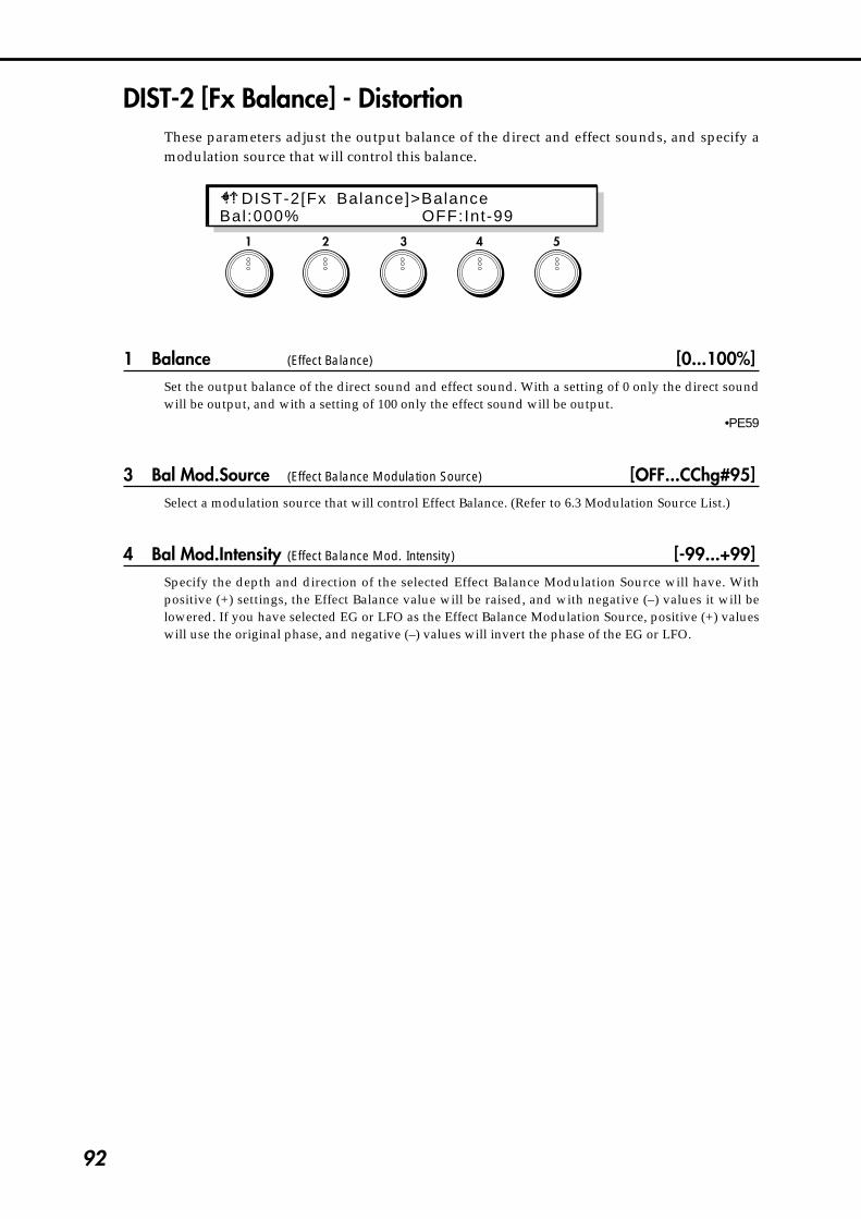
92
DIST-2 [Fx Balance] - DistortionThese parameters adjust the output balance of the direct and effect sounds, and specify amodulation source that will control this balance.
1 Balance (Effect Balance) [0...100%]Set the output balance of the direct sound and effect sound. With a setting of 0 only the direct soundwill be output, and with a setting of 100 only the effect sound will be output.
•PE59
3 Bal Mod.Source (Effect Balance Modulation Source) [OFF...CChg#95]Select a modulation source that will control Effect Balance. (Refer to 6.3 Modulation Source List.)
4 Bal Mod.Intensity (Effect Balance Mod. Intensity) [-99...+99]Specify the depth and direction of the selected Effect Balance Modulation Source will have. Withpositive (+) settings, the Effect Balance value will be raised, and with negative (–) values it will belowered. If you have selected EG or LFO as the Effect Balance Modulation Source, positive (+) valueswill use the original phase, and negative (–) values will invert the phase of the EG or LFO.
1 2 3 4 5
DIST-2[Fx Balance]>BalanceBal:000% OFF:Int-99

93
4-6. Effect S
ection
[ WAH ] - WahThis effect modifies the tone by creating an area of frequency emphasis which can be sweptup and down.
Level
Effect Balance
Wah
Sweep Source
Sweep Direction (+/-)
WAH-1 [Level & Resonance] - WahThese parameters adjust the output level of the wah, and adjust the tone of the effect.
1 Fx Level [0...99]Adjust the output level of the wah.
2 Resonance [0...99]This parameter determines the character of the sound. Higher settings will produce a stronger waheffect.
•PE60
1 2 3 4 5
WAH-1[Level & Resonance]>Fx Level Lvl :00 Reso:00
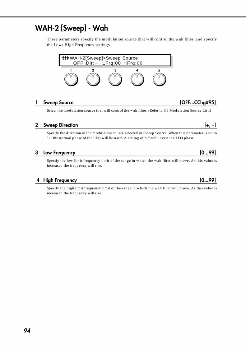
94
WAH-2 [Sweep] - WahThese parameters specify the modulation source that will control the wah filter, and specifythe Low/High Frequency settings.
1 Sweep Source [OFF...CChg#95]Select the modulation source that will control the wah filter. (Refer to 6.3 Modulation Source List.)
2 Sweep Direction [+, –]Specify the direction of the modulation source selected in Sweep Source. When this parameter is set to"+" the normal phase of the LFO will be used. A setting of “–” will invert the LFO phase.
3 Low Frequency [0...99]Specify the low limit frequency limit of the range in which the wah filter will move. As this value isincreased the frequency will rise.
4 High Frequency [0...99]Specify the high limit frequency limit of the range in which the wah filter will move. As this value isincreased the frequency will rise.
1 2 3 4 5
WAH-2[Sweep]>Sweep Source OFF Dir:+ LFrq:00 HFrq:00

95
4-6. Effect S
ection
WAH-3 [Fx Balance] - WahThese parameters set the output balance of the direct sound and effect sound, and specify amodulation source to control it.
1 Balance (Effect Balance) [0...100%]Set the output balance of the direct sound and effect sound. With a setting of 0 only the direct soundwill be output, and with a setting of 100 only the effect sound will be output.
•PE61
3 Bal Mod.Source (Effect Balance Modulation Source) [OFF...CChg#95]Select a modulation source that will control Effect Balance. (Refer to 6.3 Modulation Source List.)
4 Bal Mod.Intensity (Effect Balance Mod. Intensity) [-99...+99]Specify the depth and direction of the control that Effect Balance Modulation Source will have. Withpositive (+) settings, the Effect Balance value will be raised, and with negative (–) values it will belowered. If you have selected EG or LFO as the Effect Balance Modulation Source, positive (+) valueswill use the original phase, and negative (–) values will invert the phase of the EG or LFO.
[ UTY ] - UtilityDWU-1 [Initialize]
This utility command initializes the distortion or wah parameters of the currently selectedprogram.
1 Fx Select [DIST, WAH]Select the effect that you wish to initialize.
1 2 3 4 5
1 2 3 4 5
DWU-1 [ I n i t i a l i ze ]> Fx SelectDIST #0:Thru <Press ENTER >
WAH-3[Fx Balance]>BalanceBal:000% OFF:Int-99

96
2 Initial Type [#0...2]/[#0...3]Select one of the following basic settings.If Fx Select is DIST:
#0:Thru#1:Distortion#2:OverDrive
If Fx Select is WAH:#0:Thru#1:LFO_Wah#2:VelocityWah#3:RandomWah
Select the desired setting and press the ENTER key to execute.
If you execute #1 and #3 of WAH, the LFO4 setting will be altered.
DWU-2 [Copy]This utility command copies the distortion or wah settings of another program to thecurrently selected program.
1 Source Program [A00...C63]Select the copy source program.If you have selected C00~C63 and if no card is inserted, the display will indicate <No Card>, and theoperation will be halted.If an unformatted card is inserted, the display will indicate <Illegal Format>, and the operation will behalted.
2 Destination (Target Fx) [DIST, WAH, DIST&WAH]Select the effect that you wish to copy.Select the desired setting and press the ENTER key to execute.
1 2 3 4 5
DWU-2[Copy]>Source Program A00: Dist <Press ENTER >

97
4-6. Effect S
ection
FX-2 [Delay/Reverb]These parameters select the effect routing type and access the delay/reverb menu items.
1 Type (Delay/Reverb Select) [CHORUS&DELAY, REVERB]Select the effect routing (see p.90).CHORUS&DELAY : Effect routing 1 will be selected.REVERB : Effect routing 2 will be selected.
If CHORUS&DELAY is selected for Delay/Reverb Select
3 [DELAY] (Delay)
4 [CH/FL] (Chorus & Flanger)
5 [ UTY ] (Utility)
Items 3, 4, and 5 are menu items which select delay or chorus/flanger for editing or access the utilitycommands. [DELAY] accesses the delay settings, [CH/FL] accesses the chorus & flanger settings.[UTY] allows you to initialize or copy effect data.Use the CURSOR keys or the knobs to select the desired item, and press the ENTER key to enter theselected item.
If REVERB is selected for Delay/Reverb Select
4 [REVERB] (Reverb)
5 [ UTY ] (Utility)
Items 4 and 5 are menu items which select reverb parameters for editing or access the utilitycommands. [REVERB] accesses the reverb settings. [UTY] allows you to initialize or copy reverbsettings.Use the CURSOR keys or the knobs to select the desired item, and press the ENTER key to enter theselected item.
1 2 3 4 5
FX-2[Delay/Reverb] (Turn & PressENTER)Type:CHORUS&DELAY[DELAY] [CH/FL] [ UTY ]

98
[DELAY] - Delay* These parameters will appear if CHORUS&DELAY is selected for Delay/Reverb Select (page FX-2,2).This effect adds a time delay to the input signal. The High Damp setting allows you to adda natural-sounding decay to the delay repeats.
Delay
Feedback
Effect Balance
DLY-1 [Delay & Fback] - DelayMake settings for delay time, feedback, and high damp.
1 Delay Time [0(012[ms])...99(1200[ms])]Set the Delay Time. The maximum setting (99) produces a delay time of 1.2 seconds.
•PE65
4 Feedback [0...99]Set the amount of the output signal which is returned (fed back) to the input.
•PE66
5 High Damp [0...99]Set the amount of attenuation which is applied to the high frequencies of the feedback signal. As thisvalue is increased, the high frequencies will decay faster, producing a darker tone.
•PE67
1 2 3 4 5
DLY-1[Delay & Fback]>Delay TimeDly:00(0012[ms]) Fback:00 HDmp:00

99
4-6. Effect S
ection
DLY-2 [Fx Balance] - DelayThese parameters adjust the output balance of the direct sound and effect sound, and specifya modulation source that will control the balance.
1 Balance (Effect Balance) [0...100%]Set the output balance of the direct sound and effect sound. With a setting of 0 only the direct soundwill be output, and with a setting of 100 only the effect sound will be output.
•PE68
3 Bal Mod.Source (Effect Balance Modulation Source) [OFF...CChg#95]Select a modulation source that will control Effect Balance. (Refer to 6.3 Modulation Source List.)
4 Bal Mod.Intensity (Effect Balance Mod. Intensity) [-99...+99]Specify the depth and direction of the control that the selected Effect Balance Modulation Source willhave. With positive (+) settings, the Effect Balance will be raised, and with negative (–) values it will belowered. If you have selected EG or LFO as the Effect Balance Mod.Source, positive (+) values will usethe original phase, and negative (–) values will invert the phase of the EG or LFO.
1 2 3 4 5
DLY-2[Fx Balance]>BalanceBal:000% OFF:Int-99
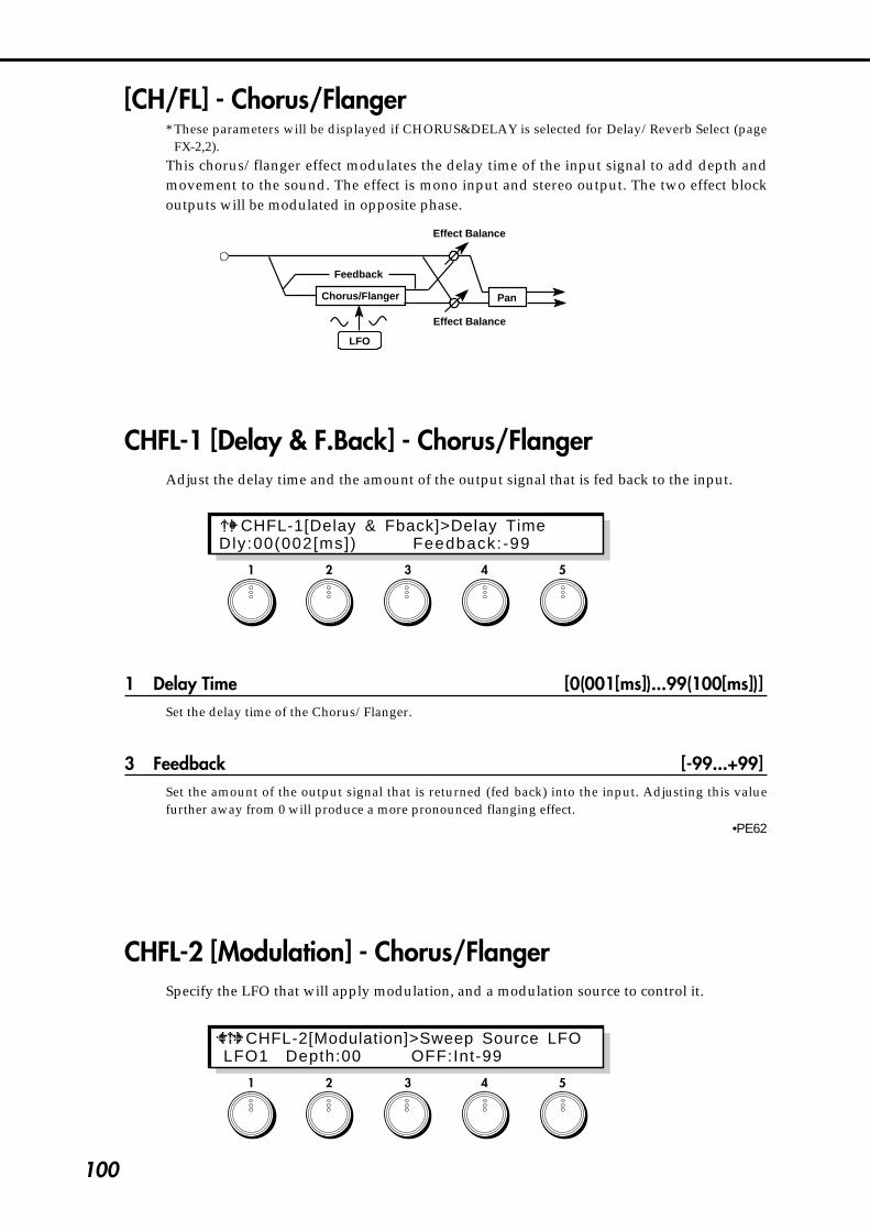
100
1 2 3 4 5
CHFL-1[Delay & Fback]>Delay TimeDly:00(002[ms]) Feedback:-99
1 2 3 4 5
[CH/FL] - Chorus/Flanger* These parameters will be displayed if CHORUS&DELAY is selected for Delay/Reverb Select (page
FX-2,2).This chorus/flanger effect modulates the delay time of the input signal to add depth andmovement to the sound. The effect is mono input and stereo output. The two effect blockoutputs will be modulated in opposite phase.
Chorus/Flanger
Feedback
Effect Balance
Effect Balance
Pan
LFO
CHFL-1 [Delay & F.Back] - Chorus/FlangerAdjust the delay time and the amount of the output signal that is fed back to the input.
1 Delay Time [0(001[ms])...99(100[ms])]Set the delay time of the Chorus/Flanger.
3 Feedback [-99...+99]Set the amount of the output signal that is returned (fed back) into the input. Adjusting this valuefurther away from 0 will produce a more pronounced flanging effect.
•PE62
CHFL-2 [Modulation] - Chorus/FlangerSpecify the LFO that will apply modulation, and a modulation source to control it.
CHFL-2[Modulation]>Sweep Source LFO LFO1 Depth:00 OFF:Int-99
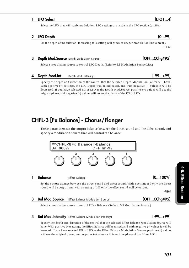
101
4-6. Effect S
ection
1 LFO Select [LFO1...4]Select the LFO that will apply modulation. LFO settings are made in the LFO section (p.118).
2 LFO Depth [0...99]Set the depth of modulation. Increasing this setting will produce deeper modulation (movement).
•PE63
3 Depth Mod.Source (Depth Modulation Source) [OFF...CChg#95]Select a modulation source to control LFO Depth. (Refer to 6.3 Modulation Source List.)
4 Depth Mod.Int (Depth Mod. Intensity) [-99...+99]Specify the depth and direction of the control that the selected Depth Modulation Source will have.With positive (+) settings, the LFO Depth will be increased, and with negative (–) values it will bedecreased. If you have selected EG or LFO as the Depth Mod.Source, positive (+) values will use theoriginal phase, and negative (–) values will invert the phase of the EG or LFO.
CHFL-3 [Fx Balance] - Chorus/FlangerThese parameters set the output balance between the direct sound and the effect sound, andspecify a modulation source that will control the balance.
1 Balance (Effect Balance) [0...100%]Set the output balance between the direct sound and effect sound. With a setting of 0 only the directsound will be output, and with a setting of 100 only the effect sound will be output.
•PE64
3 Bal Mod.Source (Effect Balance Modulation Source) [OFF...CChg#95]Select a modulation source to control Effect Balance. (Refer to 5.3 Modulation Source.)
4 Bal Mod.Intensity (Effect Balance Modulation Intensity) [-99...+99]Specify the depth and direction of the control that the selected Effect Balance Modulation Source willhave. With positive (+) settings, the Effect Balance will be raised, and with negative (–) values it will belowered. If you have selected EG or LFO as the Effect Balance Modulation Source, positive (+) valueswill use the original phase, and negative (–) values will invert the phase of the EG or LFO.
1 2 3 4 5
CHFL-3[Fx Balance]>BalanceBal:000% OFF:Int-99

102
[ UTY ] - Utility* These pages will appear if CHORUS&DELAY has been selected for Delay/Reverb Select (page
FX-2,2).
CDU-1 [Initialize]This utility command initializes the delay or chorus/flanger parameter settings of thecurrently selected program.
1 Fx Select [ CH/FL, DELAY, CH&DLY]Select the effect to be initialized.
.2 Initial Source [#0...5]/[#0...4]/[#0...2]
Select one of the following basic settings.If CH/FL is selected for Fx Select:
#0:Thru#1:LightChorus#2:DeepChorus#3:LightFlanger#4:DeepFlanger#5:FlangingDelay
If DELAY is selected for Fx Select:#0:Thru#1:LongDelay#2:MediumDelay#3:ShortDelay#4:SpringReverb
If CH&DLY is selected for Fx Select:#0:Thru#1:StereoTapDly#2:3D_Delay
Make the desired selection, and press the ENTER key to execute.
If you execute #1 ~ #4 of CH/FL and #1, #2 of CH & DLY, the LFO4 setting will also be altered.
1 2 3 4 5
C D U - 1 [ I n i t i a l i z e ] > Fx Select CH/FL #0:Thru <Press ENTER >

103
4-6. Effect S
ection
1 2 3 4 5
CDU-2 [Copy]This utility command copies the delay or chorus/flanger settings from another program tothe currently selected program.
1 Source Program [A00...C63]Select the copy source program.If you have selected C00~C63 and if no card is inserted, the display will indicate <No Card>, and theoperation will be halted.If an unformatted card is inserted, the display will indicate <Illegal Format>, and the operation will behalted.
2 Destination (Target Fx) [CH/FL, DELAY, CH/FL&DLY]Select the effect(s) that you wish to copy.
CH/FL : Chorus/FlangerDELAY : DelayCH/FL&DLY : Chorus/Flanger&Delay
Select the desired setting and press the ENTER key to execute.
CDU-2[Copy]>Source Program A00: CH/FL <Press ENTER >
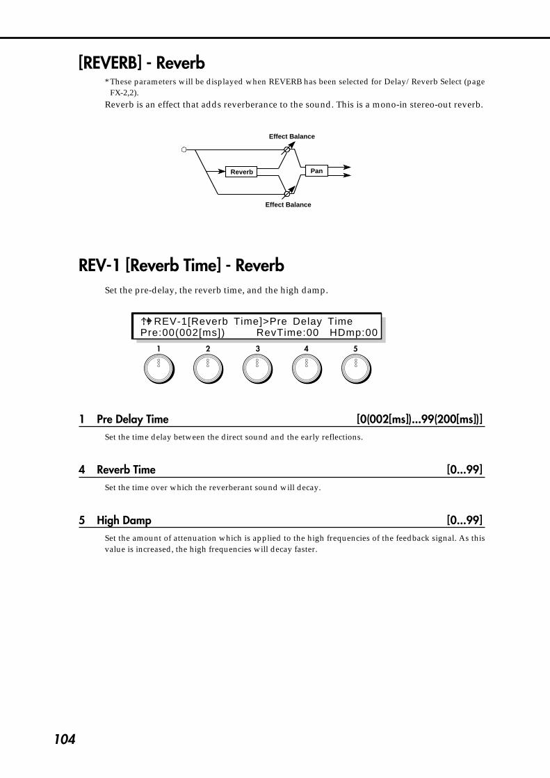
104
[REVERB] - Reverb* These parameters will be displayed when REVERB has been selected for Delay/Reverb Select (page
FX-2,2).Reverb is an effect that adds reverberance to the sound. This is a mono-in stereo-out reverb.
REV-1 [Reverb Time] - ReverbSet the pre-delay, the reverb time, and the high damp.
1 Pre Delay Time [0(002[ms])...99(200[ms])]Set the time delay between the direct sound and the early reflections.
4 Reverb Time [0...99]Set the time over which the reverberant sound will decay.
5 High Damp [0...99]Set the amount of attenuation which is applied to the high frequencies of the feedback signal. As thisvalue is increased, the high frequencies will decay faster.
1 2 3 4 5
REV-1[Reverb Time]>Pre Delay TimePre:00(002[ms]) RevTime:00 HDmp:00
Effect Balance
Effect Balance
Reverb Pan

105
4-6. Effect S
ection
REV-2 [Fx Balance] - ReverbThese parameters set the output balance between the direct sound and the effect sound, andselect a modulation source that will control the balance.
1 Balance (Effect Balance) [0...100%]Set the output balance between the direct sound and the effect sound. With a setting of 0 only the directsound will be output, and with a setting of 100 only the effect sound will be output.
•PE71
3 Bal Mod.Source (Effect Balance Modulation Source) [OFF...CChg#95]Select a modulation source to control Effect Balance. (Refer to 6.3 Modulation Source.)
4 Bal Mod.Intensity (Effect Balance Modulation Intensity) [-99...+99]Specify the depth and direction of the control that the selected Effect Balance Modulation Source willhave. With positive (+) settings, the Effect Balance will be raised, and with negative (–) values it will belowered. If you have selected EG or LFO as the Effect Balance Modulation Source, positive (+) valueswill use the original phase, and negative (–) values will invert the phase of the EG or LFO.
1 2 3 4 5
REV-2[Fx Balance]>BalanceBal:000% OFF:Int-99

106
[ UTY ] - Utility* These pages will appear if REVERB has been selected for Delay/Reverb Select (page FX-2,2).
REVU-1 [Initial]This utility command initializes the reverb parameters of a selected program.
1 Initial Source [#0...6]Select one of the following basic settings.
#0:Thru (no effect)#1:Hall#2:Room#3:Plate#4:DelayReverb#5:Stage#6:EarlyRefrection
Select the desired setting, and press the ENTER key to execute.
REVU-2 [Copy]This utility command copies the reverb parameters from another program to the currentlyselected program.
1 Source Program [A00...C63]Select the copy source program.If you have selected C00--C63 and if no card is inserted, the display will indicate <No Card>, and theoperation will be halted. If an unformatted card is inserted, the display will indicate <Illegal Format>,and the operation will be halted.
Select the desired copy source, and press the ENTER key to execute.
1 2 3 4 5
R E V U - 1 [ I n i t i a l i z e ] > I n i t i a l S o u r e c e #0:Thru <Press ENTER >
1 2 3 4 5
REVU-2[Copy]>Source Program A00: REVERB <Press ENTER >
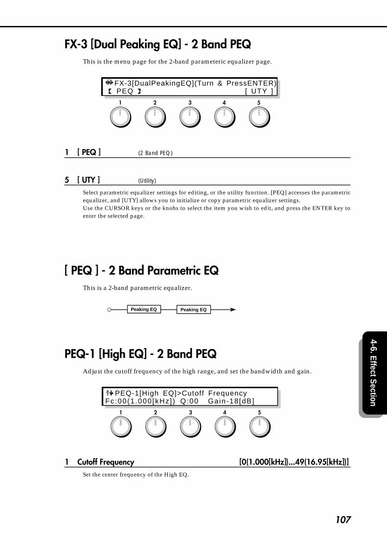
107
4-6. Effect S
ection
FX-3 [Dual Peaking EQ] - 2 Band PEQThis is the menu page for the 2-band parameteric equalizer page.
1 [ PEQ ] (2 Band PEQ)
5 [ UTY ] (Utility)
Select parametric equalizer settings for editing, or the utility function. [PEQ] accesses the parametricequalizer, and [UTY] allows you to initialize or copy parametric equalizer settings.Use the CURSOR keys or the knobs to select the item you wish to edit, and press the ENTER key toenter the selected page.
[ PEQ ] - 2 Band Parametric EQThis is a 2-band parametric equalizer.
Peaking EQ Peaking EQ
PEQ-1 [High EQ] - 2 Band PEQAdjust the cutoff frequency of the high range, and set the bandwidth and gain.
1 Cutoff Frequency [0(1.000[kHz])...49(16.95[kHz])]Set the center frequency of the High EQ.
1 2 3 4 5
FX-3[DualPeakingEQ](Turn & PressENTER) PEQ [ UTY ]
1 2 3 4 5
PEQ-1[High EQ]>Cutoff FrequencyFc:00(1.000[kHz] ) Q:00 Gain-18[dB]
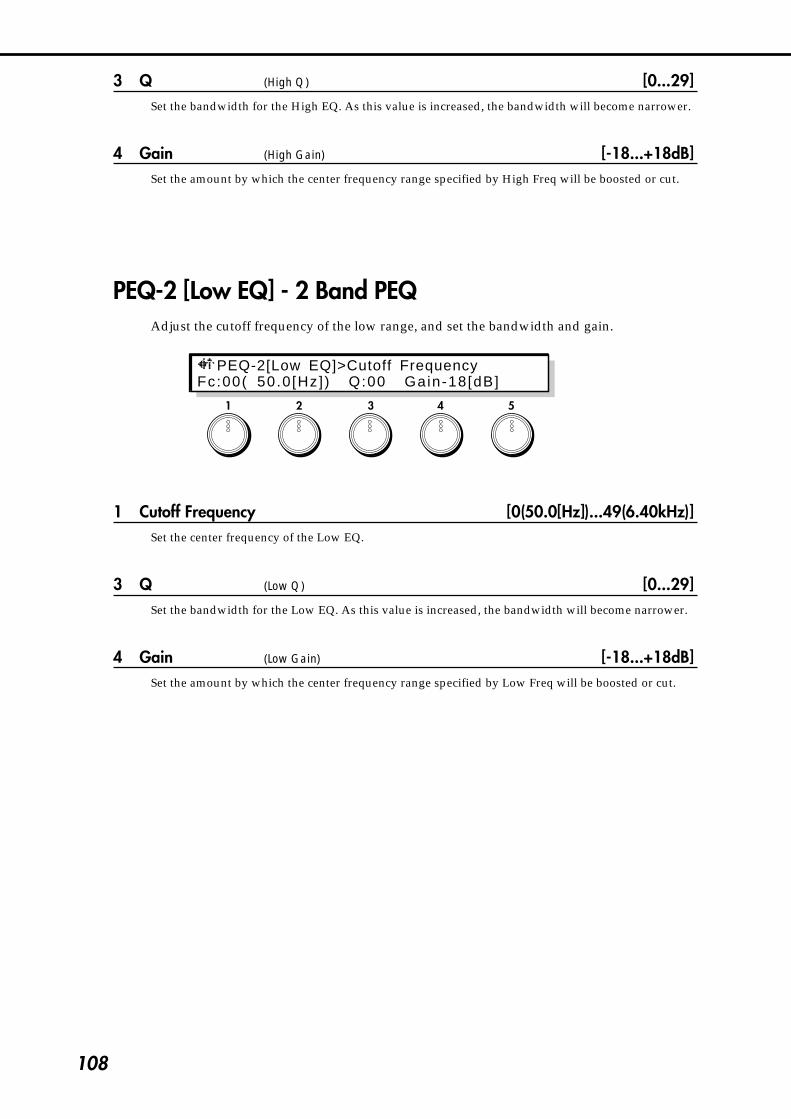
108
3 Q (High Q) [0...29]Set the bandwidth for the High EQ. As this value is increased, the bandwidth will become narrower.
4 Gain (High Gain) [-18...+18dB]Set the amount by which the center frequency range specified by High Freq will be boosted or cut.
PEQ-2 [Low EQ] - 2 Band PEQAdjust the cutoff frequency of the low range, and set the bandwidth and gain.
1 Cutoff Frequency [0(50.0[Hz])...49(6.40kHz)]Set the center frequency of the Low EQ.
3 Q (Low Q) [0...29]Set the bandwidth for the Low EQ. As this value is increased, the bandwidth will become narrower.
4 Gain (Low Gain) [-18...+18dB]Set the amount by which the center frequency range specified by Low Freq will be boosted or cut.
1 2 3 4 5
PEQ-2[Low EQ]>Cutoff FrequencyFc:00( 50.0[Hz]) Q:00 Gain-18[dB]

109
4-6. Effect S
ection
[ UTY ] - UtilityEQU-1 [Initialize]
This utility command initializes the 2 Band PEQ parameters of the currently selectedprogram.
1 Initial Type [#0...#6]Select one of the following basic settings.
#0:ThruEQ#1:2BandExciter#2:BrightEQ#3:SoftEQ#4:LowBoost#5:ReedEQ#6:BrassEQ
Select the desired setting and press the ENTER key to execute.
EQU-2 [Copy] - 2 Band PEQ UtilityThis utility command copies the 2 Band PEQ settings of another program to the currentlyselected program.
1 Source Program [A00...C63]Select the copy source program.If you have selected C00~C63 and if no card is inserted, the display will indicate <No Card>, and theoperation will be halted. If an unformatted card is inserted, the display will indicate <Illegal Format>,and the operation will be halted.
1 2 3 4 5
1 2 3 4 5
E Q U - 1 [ I n i t i a l i z e ] > I n i t i a l T y p e #0:ThruEQ <Press ENTER >
EQU-2[Copy]>Source Program A00: DualPeakingEQ <Press ENTER >

110
FX-4 [Panpot & Output Level] - Panpot & LevelThese parameters set the L/R pan position of the output signal, and specify a modulationsource to control it. The output level setting for the entire program is also made here.
1 Panpot [LEFT, L 63...CENTER...62➔R, RIGHT]Set the L/R pan position of the output signal. A setting of LEFT places the signal fully left, and a settingof RIGHT fully right.
•PE72
2 Panpot Mod.Src (Panpot Modulation Source) [OFF...CChg#95]Select a modulation source to control Panpot. (Refer to 6.3 Modulation Source List.)
3 Panpot Mod.Int (Panpot Mod. Intensity) [-99...+99]Specify the depth and direction of the control that the selected Panpot Modulation Source will have.With positive (+) settings, the Panpot value will be raised, and with negative (–) values it will belowered. If you have selected EG or LFO as the Panpot Modulatiion Source, positive (+) values will usethe original phase, and negative (–) values will invert the phase of the EG or LFO.
5 Output Level [0...127]Set the output level for the entire effect system.
1 2 3 4 5
FX-4[Pan & OutputLevel]>Panpot LEFT OFF:Int-99 OutputLevel:000
➔

111
4-7.E
G S
ection
4-7. EG (Envelope Generator) SectionHere you can make settings for the four general-purpose EGs (envelope generators). Each EGcan be used as a modulation source for parameters in any section (other than EG, COMMON,or GLOBAL) to apply time-variant change.
EG-1 [EG Menu]This is the EG menu page.
1 [ EG1 ]
2 [ EG2 ]
3 [ EG3 ]
4 [ EG4 ]
5 [ UTY ] (Utility)
Select the EG that you wish to edit, or select the utility page. [EG1]~[EG4] contain the settings for eachEG. [UTY] allows you to initialize or copy EG settings.Use the CURSOR keys or rotate the knobs to select the desired item, and press the ENTER key to enterthe selected page. The parameter structure is identical for [EG1]~[EG4]. For [EG2]~[EG4] refer to theexplanation for EG1-1…EG1-4.
1 2 3 4 5
EG-1[EG Menu] (Turn & Press ENTER) EG1 [ EG2 ] [ EG3 ] [ EG4 ] [ UTY ]

112
1 2 3 4 5
EG1-1[EG Level ]>Start LevelStaL+00 AtkL+99 BrkL+50 SusL+70 RlsL+00
[ EG1 ]EG1-1 [EG Level]
These parameters set the levels for EG1.
1 Start Level [-99...+99]Set the level at key-on.
•PE73 : EG1 •PE87 : EG2 •PE101 : EG3 •PE115 : EG4
2 Attack Level [-99...+99]Set the level that will be reached after the Attack Time elapses.
•PE75 : EG1 •PE89 : EG2 •PE103 : EG3 •PE117 : EG4
3 Break Level [-99...+99]Set the level that will be reached after the Decay Time elapses.
•PE77 : EG1 •PE91 : EG2 •PE105 : EG3 •PE119 : EG4
4 Sustain Level [-99...+99]Set the level that will be reached after the Slope Time elapses.
•PE79 : EG1 •PE93 : EG2 •PE107 : EG3 •PE121 : EG4
5 Release Level [-99...+99]Set the level that will be reached after the Release Time elapses after key-off.
•PE81 : EG1 •PE95 : EG2 •PE109 : EG3 •PE123 : EG4
Key-offAttack Level Sustain Level
Key-on
0
-99
+99
AttackTime
DecayTime
SlopeTime
ReleaseTime
Time
BreakLevel

113
4-7.E
G S
ection
1 2 3 4 5
EG1-2 [EG Time]These parameters set the times for EG1.
2 Attack Time [0...99]Set the time from key-on until the Attack Level value is reached.
•PE74 : EG1 •PE88 : EG2 •PE102 : EG3 •PE116 : EG4
3 Decay Time [0...99]Set the time from when the Attack Time ends until the Break Point value is reached.
•PE76 : EG1 •PE90 : EG2 •PE104 : EG3 •PE118 : EG4
4 Slope Time [0...99]Set the time from when the Decay Time ends until the Sustain Level value is reached.
•PE78 : EG1 •PE92 : EG2 •PE106 : EG3 •PE120 : EG4
5 Release Time [0...99]Set the time from key-off until the Release Level is reached.
•PE80 : EG1 •PE94 : EG2 •PE108 : EG3 •PE122 : EG4
EG1-2[EG Time]>Attack Time AtkzT:30 DcyT:30 SlpT:10 RlsT:30
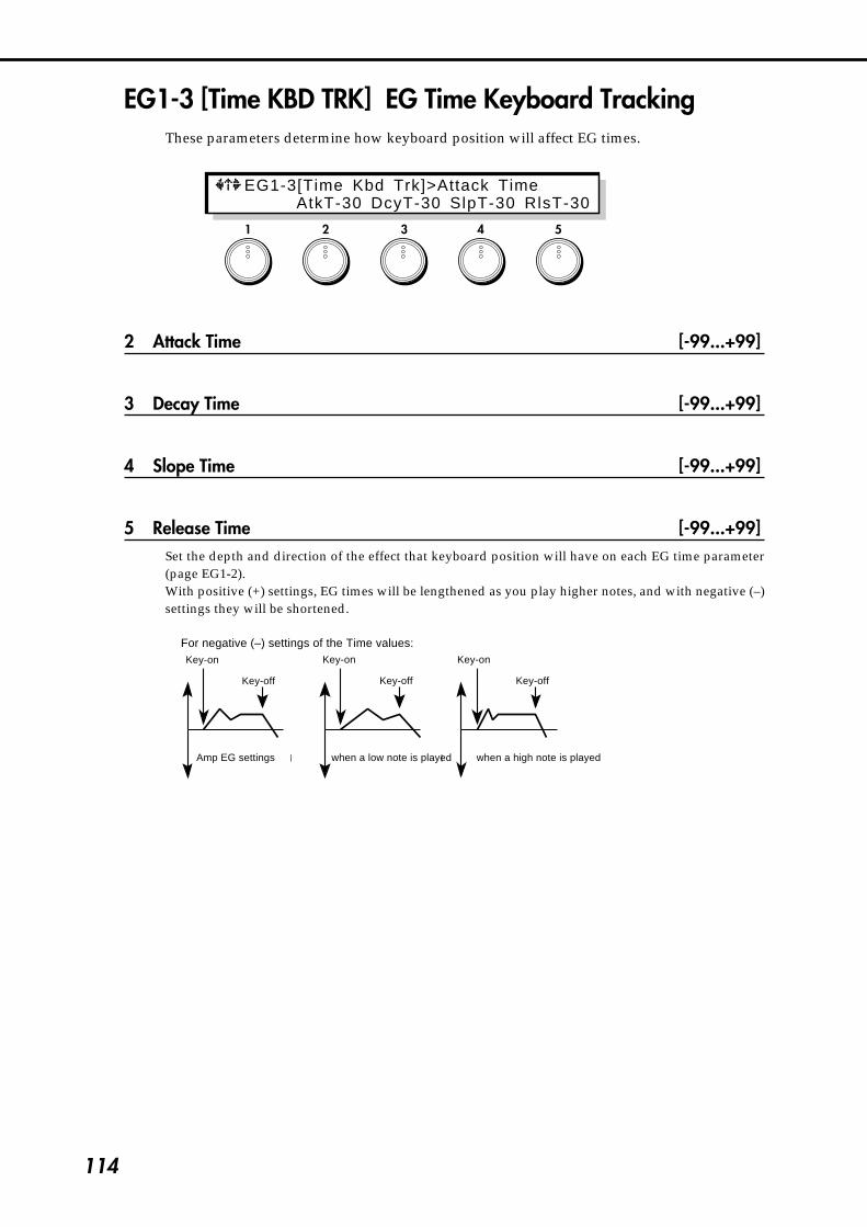
114
1 2 3 4 5
EG1-3 [Time KBD TRK] EG Time Keyboard TrackingThese parameters determine how keyboard position will affect EG times.
2 Attack Time [-99...+99]
3 Decay Time [-99...+99]
4 Slope Time [-99...+99]
5 Release Time [-99...+99]Set the depth and direction of the effect that keyboard position will have on each EG time parameter(page EG1-2).With positive (+) settings, EG times will be lengthened as you play higher notes, and with negative (–)settings they will be shortened.
各タイムを-の値に設定した場合�
キー・オン�
キー・オフ�
キー・オン�
キー・オフ�
キー・オン�
キー・オフ�
Amp EGによる設定� 低い音程を弾いたとき� 高い音程を弾いたとき�
For negative (–) settings of the Time values:Key-on Key-on Key-on
Key-off Key-off Key-off
Amp EG settings when a low note is played when a high note is played
EG1-3[Time Kbd Trk]>Attack Time AtkT-30 DcyT-30 SlpT-30 RlsT-30

115
4-7.E
G S
ection
EG1-4 [Velocity Control]These parameters determine how keyboard playing dynamics (velocity) will affect EG levelsand times.
1 EG Level [-99...+99]Specify the depth and direction of the effect that velocity will have on EG levels. With positive (+)settings, EG levels will be increased as you play more strongly. With negative (-) settings, EG levels willbe decreased as you play more strongly.
•PE82 : EG1 •PE96 : EG2 •PE110 : EG3 •PE124 : EG4
Levelを+の値に設定した場合�
キー・オン�キー・オフ�
キー・オン�
キー・オフ�
キー・オン�
キー・オフ�
Amp EGによる設定� 弱く弾いたとき� 強く弾いたとき��
2 Attack Time [-99...+99]•PE83 : EG1 •PE97 : EG2 •PE111 : EG3 •PE125 : EG4
3 Decay Time [-99...+99]•PE84 : EG1 •PE98 : EG2 •PE112 : EG3 •PE126 : EG4
4 Slope Time [-99...+99]
•PE85 : EG1 •PE99 : EG2 •PE113 : EG3 •PE127 : EG4
5 Release Time [-99...+99]Specify the depth and direction of the effect that velocity will have on EG times.With positive (+) settings, EG times will be lengthened as you play more strongly, and with negative(-) settings they will be shortened.
•PE86 : EG1 •PE100 : EG2 •PE114 : EG3 •PE128 : EG4
各タイムを-の値に設定した場合�
キー・オン�
キー・オフ�
キー・オン�
キー・オフ�
キー・オン�
キー・オフ�
Amp EGによる設定� 弱く弾いたとき� 強く弾いたとき�
1 2 3 4 5
For positive (+) Level settings:
Key-on Key-on Key-on
Key-off Key-offKey-off
Amp EG settings softly played note strongly played note
For negative (–) settings of the Time parameters:
Key-on Key-on Key-on
Key-off Key-off Key-off
Amp EG settings softly played note strongly played note
EG1-4[Veloc i ty Contro l ]>EG LevelLvl+99 AtkT-50 DcyT-50 SlpT-50 RlsT-50

116
[ EG2 ] EG2-1...4
[ EG3 ] EG3-1...4
[ EG4 ] EG4-1...4The contents of the parameters are identical to EG1. Refer to the explanations for page EG1-1…4.
[ UTY ] - UtilityEGU-1 Initialize
This utility command initializes the specified EG (1~4).
1 EG Select [EG1...EG4]Select the EG to initialize.
2 Initial Type [#00...10]Select one of the following 11 basic EG settings for the EG specified by EG Select.
#00:Default#01:Piano#02:Bell#03:Guitar#04:Percussion#05:Organ#06:SoftAttack#07:SlowAttack#08:SoloString#09:Sweep#10:Pressure
Select the desired setting and press the ENTER key to execute.
1 2 3 4 5
EGU-1 [ In i t i a l i ze ]>EG Se lec t EG1 #00:Default <Press ENTER >

117
4-7.E
G S
ection
1 2 3 4 5
1 2 3 4 5
EGU-2[Copy]>Source Program EDIT: EG1 EG1 <Press ENTER >
EGU-2 CopyThis utility command copies the EG parameter settings from another program to thecurrently selected EG.
1 Source Program [EDIT, A00...C63]Select the copy source program. If you select EDIT, the currently edited program (the program incurrent memory) will be selected.If you have selected C00~C63 and if no card is inserted, the display will indicate <No Card>, and theoperation will be halted. If an unformatted card is inserted, the display will indicate <Illegal Format>,and the operation will be halted.
2 Source EG [EG1...4, ALL]Select the copy source EG. If you select ALL, the following Destination setting will be ignored.
3 Destination (Target EG) [EG1...4]Select the copy destination (current) EG.
Make the desired selection, and press the ENTER key to execute.
If the Source Program is set to EDIT and the Source EG and Destination are identical, the displaywill indicate <Ignore > and the operation will be halted.
EGU-3 SwapThis utility command exchanges the settings of two EGs within the currently selected program.
1 EG Select [EG1...4]Select one EG program to swap.
2 Another Select [EG1...4]Select another EG program to swap EG.To execute the swap command, press the ENTER key.
EGU-3[Swap]>EG Select EG1 EG1 ModS:NO <Press ENTER >

118
1 2 3 4 5
LFO-1[LFO Menu] (Turn & Press ENTER) LFO1 [ LFO2 ][ LFO3 ][ LFO4 ] [ UTY ]
4-8. LFO SectionHere you can make settings for the four general-purpose LFOs. These can be used asmodulation sources for the parameters of each section (except for COMMON and GLOBAL),allowing you to apply cyclic change to the sound.
LFO-1 [LFO Menu]This is the LFO menu page.
1 [LFO1]
2 [LFO2]
3 [LFO3]
4 [LFO4]
5 [UTY] (Utility)
Select the LFO that you wish to edit, or select the utility functions. [LFO1]~[LFO4] access the settings ofeach LFO. [UTY] allows you to initialize or copy LFO settings.Use the CURSOR keys or rotate the knobs to select the desired item, and press the ENTER key to enterthe selected page.The parameter structure of [LFO1]~[LFO4] is identical. For details on [LFO2]~[LFO4], refer to theexplanation for LFO1-1…LFO1-4.

119
4-8.L
FO
[LFO1]LFO1-1 [Wave & Mode]
These parameters let you select the waveform for LFO1, and specify how key on/off timingwill affect the LFO. You can also specify whether or not the LFO period will synchronize itselfto begin at key-on.
1 Wave Form [0...29]Select the LFO waveform.
•PE129 : LFO1 •PE134 : LFO2 •PE139 : LFO3 •PE144 : LFO4
1 2 3 4 5
SIN '0
1 cycle
1/2 cycle
1 cycle
1/2 cycle
a b
1/2 cycle
1 cycle
SIN '180
COS '0
COS '180
TRI '0
TRI '90
TRI '180
TRI '270
SAWUP '0
SAWUP '180
RANDOM5/6
RANDOM3/4
RANDOM2
RANDOM1
SQR '180
SQR '0
SAWDOWN '180
SAWDOWN '0 Growl
GuitarVib
Step TRI
Step SAW
Step TRI4
Step SAW6
Exp TRI
Exp SAW UP
Exp SAW DOWN
Str Vib
The amplitude of the LFO changes randomly for each cycle.
The amplitude of the LFO changes randomly for each half cycle.
Random 3: the amplitude of the LFO changes randomly for each cycle.
Random 4: the amplitude of the LFO changes randomly for each half cycle.
Random 5: the a:b ratio changes randomly for each cycle.
Random 6: the a:b ratio changes randomly for each half cycle.
* The range of a:b change is 1.0 < a:b < 0.1
LFO1-1[Wave & Mode]>Wave Form#00:SIN'0 Mode:OFF KeySync:OFF

120
3 Mode [ON, OFF, BOTH]Specify the time when the LFO begins to apply. This will be affected by the settings of Delay (pageLFO1-4,4) and Fade In (page LFO1-4,5).With a setting of ON, the LFO will begin to apply at key-on. Normally you will set this parameter ON.With a setting of OFF, the LFO will begin to apply at key-off.With a setting of BOTH, the LFO will begin to apply at key-on, and will stop at key-off.
Key On Key Off
Delay
Key On Key Off
DelayDelay
Key On Key Off Key On Key OffKey On Key Off
DelayDelayDelay Delay
Key On Key Off
Delay
Mode = Off
時間�
Mode = On
時間�
Mode = Both
時間�
Mode = Off
時間�
Mode = On
Fade +
Fade - 時間�
Mode = Both
時間�
5 Key Sync SW (Key Sync Switch) [OFF, ON]With a setting of OFF, subsequently-played notes will use the effect of the LFO that was started by thefirst-played note. (In this case, the Delay and Fade In settings will have no effect.)With a setting of ON, the LFO will start again each time a key is pressed, and an independent LFO willoperate for each key.
Key On Key On
Key Sync SW = On
Key On Key On
Key Sync SW = Off
Time Time Time
Time Time Time

121
4-8.L
FO1 2 3 4 5
LFO1-2 [Frequency]These parameters set the speed of the LFO, and specify the depth and direction of the effectthat keyboard tracking and control change #1 will have on LFO speed.
1 Frequency [0(0.000[Hz])....199(60.00[Hz])]Set the speed of the LFO.
•PE130 : LFO1 •PE135 : LFO2 •PE140 : LFO3 •PE145 : LFO4
3 Frequency Kbd Track (Frequency Keyboard Tracking) [-99...+99]Specify how keyboard position will affect the LFO speed. With positive (+) settings, the LFO speed willbecome faster as you play higher notes. With negative (–) settings, the opposite effect will occur.
4 Frequency CC#1 Ctrl (Frequency CC#1 Control) [-99...+99]Specify how control change #1 will affect the LFO speed.
LFO1-3 [Modulation Source]These parameters specify a modulation source that will control LFO speed, and set theintensity of the control.
1 Mod.Source (Frequency Modulation Source) [OFF...CChg#95]Select a modulation source that will control LFO speed. (Refer to 6.3 Modulation Source List.)
2 Mod.Intensity (Frequency Modulation Intensity) [-99...+99]This specifies the depth and direction of the adjustment that the controller will make to the LFO speedspecified by the Frequency setting (page LFO1-2,1). If you have selected EG or LFO as the FrequencyModulation Source, positive (+) values will use the original phase, and negative (–) values will invertthe phase of the EG or LFO.
1 2 3 4 5
LFO1-2[Frequency]>Frequency 099(5.000[Hz]) KTr-99 CC#1+00
LFO1-3[Frequency Mod]>Mod.Source EG1:Int+05

122
LFO1-4 [Amplitude]These parameters specify a modulation source that will control the level of the LFO waveformand set the intensity of the control, and also specify how the LFO effect will change over time.
1 Modulation Source (Amplitude Modulation Source) [OFF...CChg#95]Select a modulation source that will control the level of the LFO waveform. (Refer to 6.3 ModulationSource List.)
2 Modulation Intensity (Amplitude Mod. Intensity) [-99...+99]Specify the depth and direction of the control that the selected Amplitude Modulation Source will have onthe LFO waveform level. If you have selected EG or LFO as the Amplitude Modulation Source, positive (+)values will use the original phase, and negative (–) values will invert the phase of the EG or LFO.
•PE132 : LFO1 •PE137 : LFO2 •PE142 : LFO3 •PE147 : LFO4
3 Offset [-99...+99]Specify the center value of the LFO waveform.
•PE131 : LFO1 •PE136 : LFO2 •PE141 : LFO3 •PE146 : LFO4
Offset = 0
Offset = 50
Offset = -50
Parameter value being modulated
Amplitude of modulation specified by Modulation Intensity
Parameter value being modulated
Amplitude of modulation specified by Modulation Intensity
Parameter value being modulated
Amplitude of modulation specified by Modulation Intensity
4 Delay [0...99]Specify the time delay after key-on until the LFO begins to take effect.
5 Fade In [-99...+99]Specify the time over which the LFO takes full effect. With positive (+) settings, the effect of the LFOwill gradually increase up to the full value specified by the parameters. With negative (-) settings, theeffect of the LFO will begin with the full value specified by the parameters, and will then graduallydiminish to no effect.
•PE133 : LFO1 •PE138 : LFO2 •PE143 : LFO3 •PE148 : LFO4
1 2 3 4 5
Parameter valuebeing modulated
Parameter valuebeing modulated
Parameter valuebeing modulated
Amplitude of modulationspecified by Modulation Intensity
Amplitude of modulationspecified by Modulation Intensity
Amplitude of modulationspecified by Modulation Intensity
LFO1-4[Amplitude]>Modulation Source LFO1:Int+60 Ofst+20 Dly:05 FIn+10

123
4-8.L
FO
[LFO2] LFO2-1...4
[LFO3] LFO3-1...4
[LFO4] LFO4-1...4The [LFO2], [LFO3], and [LFO4] parameters are identical in structure to the [LFO1] parameters. Referto the explanation for LFO1-1…4.
[ UTY ] - Utility
LFOU-1 [Copy]This utility command copies LFO parameter settings from another program to the currentlyselected LFO.
1 Source Program [EDIT, A00...C63]Select the copy source program number. If you select EDIT, the program currently being edited (theprogram called into current memory) will be selected.If you select C00~C63 and if a card is not inserted when you execute, the display will indicate <NoCard>, and the operation will be halted.If an un-formatted card is inserted, the display will indicate <Illegal Format>, and the operation will behalted.
2 Source LFO [LFO1...4, ALL]Select the copy source LFO. If you select ALL, the following Destination setting will be ignored.
3 Destination (Target LFO) [LFO1...4]Select the copy destination (current) LFO.
Make the desired selection, and press the ENTER key to execute.
If the Source Program is EDIT, setting the Source LFO and the Destination to the same settingswill result in a message of <Ignore >, and the operation will be halted.
1 2 3 4 5
LFOU-1[Copy]>Source Program EDIT: LFO1 LFO4 <Press ENTER >
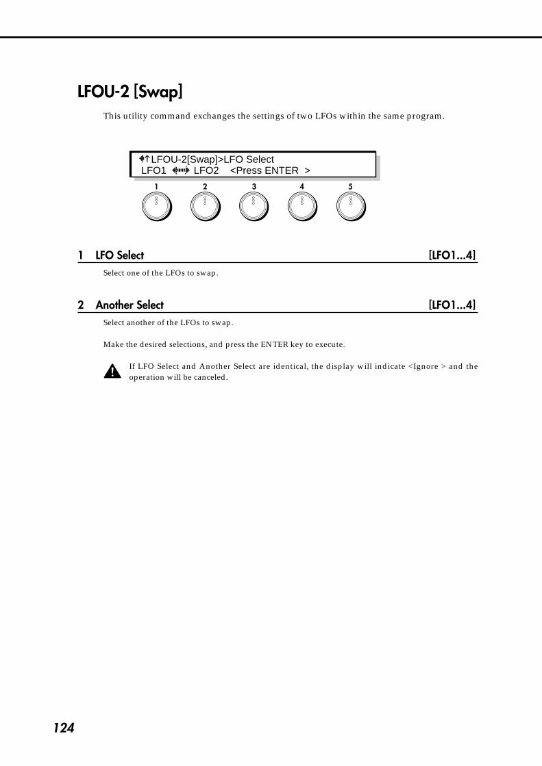
124
1 2 3 4 5
LFOU-2 [Swap]This utility command exchanges the settings of two LFOs within the same program.
1 LFO Select [LFO1...4]Select one of the LFOs to swap.
2 Another Select [LFO1...4]Select another of the LFOs to swap.
Make the desired selections, and press the ENTER key to execute.
If LFO Select and Another Select are identical, the display will indicate <Ignore > and theoperation will be canceled.
LFOU-2[Swap]>LFO Select LFO1 LFO2 <Press ENTER >

125
4-9. Com
mon S
ection
4-9. Common SectionSpecify the name of a program, its scale, and controller functions etc.
CMN-1 [Program Name]Assign a name of up to 16 characters to the program.
Use knob 4 or the cursor keys to move the CURSOR, and use the VALUE key or knob 5 toselect characters. Use the ENTER key to enter a space, and the EXIT key to delete a character.
To name a program, first use the CURSOR keys or knob 4 to make the cursor appear. Then youwill be able to select characters.
To save the program name, be sure to write the program into memory. If you select anotherprogram or turn the power off, your changes will be lost.
The following characters are available.
! " $ % & ’ - . / 0 1 2 3 4 5 6 7 8 9 : ; < = > ? ( ) * + ,#
@ A B C D E F G H I J K L M N O P Q R S T U V W X Y Z [ ‰ ] ^ _
a b c d e f g h i j k l m n o p q r s t u v w x y z {� }�‡ †
1 2 3 4 5
CMN-1[Program Name]Prophet ic Steps! [ ˚ ¬ ] [ CHAR ]
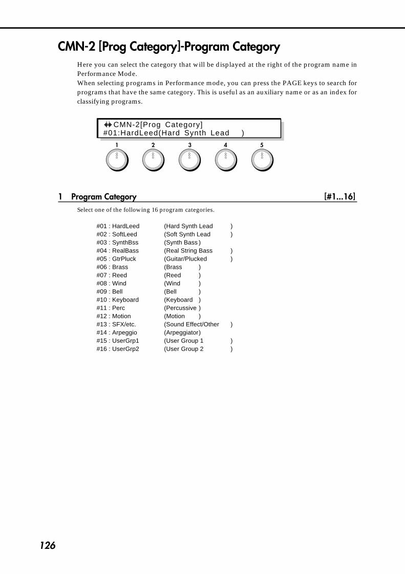
126
CMN-2 [Prog Category]-Program CategoryHere you can select the category that will be displayed at the right of the program name inPerformance Mode.When selecting programs in Performance mode, you can press the PAGE keys to search forprograms that have the same category. This is useful as an auxiliary name or as an index forclassifying programs.
1 Program Category [#1...16]Select one of the following 16 program categories.
#01 : HardLeed (Hard Synth Lead )#02 : SoftLeed (Soft Synth Lead )#03 : SynthBss (Synth Bass )#04 : RealBass (Real String Bass )#05 : GtrPluck (Guitar/Plucked )#06 : Brass (Brass )#07 : Reed (Reed )#08 : Wind (Wind )#09 : Bell (Bell )#10 : Keyboard (Keyboard )#11 : Perc (Percussive )#12 : Motion (Motion )#13 : SFX/etc. (Sound Effect/Other )#14 : Arpeggio (Arpeggiator)#15 : UserGrp1 (User Group 1 )#16 : UserGrp2 (User Group 2 )
1 2 3 4 5
CMN-2[Prog Category]#01:HardLeed(Hard Synth Lead )

127
4-9. Com
mon S
ection
CMN-3 [Voice Control]These parameters determine how processing will take place when a note is played.
1 Key Priority [LAST, HIGH, LOW]This setting determines which note will sound when two or more keys are pressed simultaneously.
LAST: The last-pressed note will sound.LOW: The lowest of the simultaneously pressed notes will sound.HIGH: The highest of the simultaneously pressed notes will sound.
2 Hold [OFF, ON]This parameter specifies whether or not a note will continue sounding after the key is released. WhenHold is ON, a note will continue to sound even after the key is released. However if the Sustain Level isset to 0 for the EG selected as the Amp Mod.EG (in AMP section page AMP1-2,1 or 2-2,1), the sound willdecay naturally.
3 Trigger Mode [MULTI, SINGLE, VELOCITY]This parameter determines how the EG and LFO will be affected by key-on.MULTI (multi trigger): For every key-on, EGs will begin operation from the Start Level, and LFOswhose Key Sync (page LFO1~4-1,5) is ON will be reset.SINGLE (single trigger): When (and only when) a key-on occurs when all keys are off, EGs will returnto the Start Level and LFOs (whose Key Sync is ON) will be reset.VELOCITY (velocity): Multi trigger and Single trigger will be switched depending on the velocity.
4 Above Below [ABOVE, BELOW]Refer to 5 Threshold Velocity.
5 Threshold Velocity [1...127]When the Trigger Mode is set to VELOCITY, this parameter specifies the velocity value at which Multiand Single triggering will be switched. If the Above Below parameter is set to ABOVE, Multi triggerwill be used for notes with a velocity above the Threshold Velocity. If the Above Below parameter is setto BELOW, Multi triggering will be used for notes with a velocity below the Threshold Velocity.
1 2 3 4 5
CMN-3[Voice Cont ro l ]>Key Pr ior i ty LAST Hold:OFF MULTI ABOVE Thrsh:001

128
CMN-4 [Scale]These parameters specify the scale. You can also cause the pitch to be randomly varied fromthe selected scale.
1 Scale Type [EQUAL_TEMP...USER_SCALE_2]Select one of the following 16 types of scale.
EQUAL TEMPERAMENT:This is the most commonly used scale, in which each semitone interval is identical to all others.PURE MAJOR:In this scale, the principle major chords in the key selected by Scale Key will be perfectly in tune.PURE MINOR:In this scale, the principle minor chords in the key selected by Scale Key will be perfectly in tune.ARABIC:This is a quarter-tone scale used in Arabian music. For “rast do/bayati re” set Scale Key to C; for “rastre/bayati mi” use D; for “rast fa/bayati sol” use F; for “rast sol/bayati la” use G; for “rast si flat/bayatido” use A#.PYTHAGOREAN:This scale takes its name from the famous mathematician of ancient Greece, and is effective for melodicplaying.WERCKMEISTER:This is a scale used in the later Baroque period.KIRNBERGER:This is a scale created in the 18th century for the harpsichord.SLENDRO:This is an Indonesian Gamelan scale in which octaves consist of five notes. When the Scale Key is C, thenotes C, D, F, G, and A are used.PELOG:This is an Indonesian Gamelan scale in which octaves consist of seven notes. When the Scale Key is C,the notes C, D, E, F, G, A, and B are used.USER SCALE 1:This is a user-adjustable scale that allows you to specify the pitch of each note in the octave. Thespecified pitches are applied to each octave. Make settings in Global section page GLB-3.USER SCALE 2:This is a user-adjustable scale that allows you to specify the pitch of each note in the entire range(C-1~G9). Make settings in Global section page GLB-3.
3 Scale Key [C...B]Specify the key (tonic) of the scale.
5 Random Pitch Intensity [0...99]Specify the depth at which the pitch will be varied randomly.Higher settings of this parameter will produce an increasing degree of randomness in the pitch of eachnote when it is played. Normally you will leave this set to 0. This parameter is useful when you wish tosimulate instruments whose pitch is inherently unpredictable, such as analog synthesizers or acousticinstruments.
1 2 3 4 5
CMN-4[Scale]>Scale Type EQUAL–TEMP Key:C RandPitchInt:00

129
4-9. Com
mon S
ection
CMN-5 [Wheel1/2 Assign]These parameters specify the function of Wheel Controllers 1 and 2.
1 Control Wheel 1 [0(OFF)...100(CChg#95)]Specify the function of the Wheel 1 controller. You can select from Pitch Bend (+/–, +, –), Aftertouch,and Control Change numbers 0~95.
4 Control Wheel 2 [0(OFF)...100(CChg#95)]Specify the function of the Wheel 2 controller. You can select from Pitch Bend (+/–, +, –), Aftertouch,and Control Change numbers 0~95.
+
–
0
PBend+–
Wheel1 Wheel2
+
+
0
PBend+ATouch
CChag#00...95
–
–
0
PBend–
+
–
0
PBend+–
+
0
PBend+ATouch
CChag#00...95
–
0
PBend–
CMN-6 [Wheel3 Assign] - Wheel Controller3 AssignThese parameters specify the functions of the Wheel 3 controller.
1 Wheel3 +Direction [0(OFF)...100(CChg#95)]Specify the function of the Wheel 3 controller when it is moved away from yourself. You can select fromPitch Bend (+/–, +, –), Aftertouch, and Control Change numbers 0~95 (refer to the diagram on thefollowing page).
4 Wheel3 -Direction [0(OFF)...100(CChg#95)]Specify the function of the Wheel 3 controller when it is moved toward yourself. You can select fromPitch Bend (+/–, +, –), Aftertouch, and Control Change numbers 0~95 (refer to the diagram on thefollowing page).
1 2 3 4 5
1 2 3 4 5
CMN-6[Wheel3 Assign]>Wheel3 +Direction +:000( OFF ) - :000( OFF )
CMN-5[Wheel1/2 Assign]>Control Wheel1Whl1:000( OFF ) Whl2:000( OFF )

130
CMN-7 [Ribbon Assign]These parameters specify the function of the Ribbon controller, and specify the location onthe X-axis which will be the zero point.
1 Ribbon X (RibbonController-X) [0(OFF)...100(CChg#95)]Specify the function that the Ribbon controller will have when it is moved to left or right. You can selectfrom Pitch Bend (+/–, +, –), Aftertouch, and Control Change numbers 0~95.
3 X Variable Center (X Variable 0 Point) [OFF, ON]When this is set OFF, the center of the Ribbon controller will be 0.When this is set ON, the location where you begin stroking horizontally will be 0.
4 Ribbon Z (RibbonController-Z) [0(OFF)...100(CChg#95)]Specify the function that the Ribbon controller will have when it is pressed strongly. You can selectfrom Pitch Bend (+/–, +, –), Aftertouch, and Control Change numbers 0~95.
X Valiable 0 PointがOFFのとき� リボンコントローラの左端が0になります(PBend+-では中央部が0)。� X Valiable 0 PointがONのとき� リボンコントローラに触れた最初の位置が0になります。�
Ribbon Z
Ribbon X
WHEEL3+
WHEEL3 HOLD
WHEEL3 –
Wheel3を操作してaの位置でWHEEL3 HOLDキーを押すと�Wheel3を中央部に戻してもaでの効果がかかり続けます。�この状態でbへホイールを動かすと、さらにWheel3-で設定�している効果が同時にかかります。�
*1はWheel3+またはWheel3–の一方にPBend+–を割り当てた場合。�*2はWheel3+とWheel3–の両方にPBend+–を割り当てた場合、� もしくはWheel3+にPBend+を、Wheel3–にPBend–を割り当てた場合。�
�
�a
�
b
+
0
+
+
+
–
0
PBend+–
+
0
PBend+ATouch
CChg#0...95
–
–
–
–
0
+
0
+ –PBend–
*1*2
–
PBend+–
PBend+–
0
PBend+ATouch
CChg#0...95
PBend+ATouchCChg#0...95
0
+
0
+ –PBend–
PBend–
0
0
0
�
Please be aware that if you assign PBend+– to Ribbon Z, or to either Wheel 3+ or Wheel 3-,modulation may keep being applied continuously for some settings.
1 2 3 4 5
When you rotate Wheel 3 to position 'a' and press the WHEEL 3 HOLD key, theeffect of 'a' will be maintained even after you return to Wheel 3 to the center. Nowyou can move the wheel to position 'b' to apply the effect selected for Wheel3-, sothat two effects are applied simultaneously.
When X Variable 0 Point is OFF,the left end of the ribbon controller will be 0 (with PBend+–, the center will be 0).When X Variable 0 Point is ON,the location where you first touch the ribbon controller will be 0.
CMN-7[RibbonAssign]>Ribbon XX:000( OFF ) XVC:OFF Z:000( OFF )
*1 is when PBend+- is assigned to either Wheel3+ or Wheel3-.*2 is when PBend+- is assigned to both Wheel3+ and Wheel3-, or ifPBend+ is assigned to Wheel3+ and PBend- is assigned to Wheel3-.

131
4-9. Com
mon S
ection
CMN-8 [Pedal & SW Assign]These parameters specify the functions controlled by the optional expression pedal and footswitch.For details, refer to the explanation of connections in the Basic Guide.
1 FootPedal [0(OFF)...100(CChg#95)]Specify the function that will be controlled when the expression pedal is operated. You can select fromPitch Bend (+/–, +, –), Aftertouch, and Control Change numbers 0~95.
4 Foot SW (Foot Switch) [OFF...Wh3Hold]Specify the function that the foot switch will have. You can select from the following 13 functions.
Off No effectSustain Sustain on/offProgram Up Select the next programProgram Down Select the previous programOctave Up 1 octave upOctave Down 1 octave downProtamento SW Portamento on/offDistortion SW Distortion on/offWah SW Wah on/offChorus SW Chorus on/offDelay SW Delay on/offReverb SW Reverb on/offArpeggio OFF/ON Arpeggiator function on/offWheel3 Hold Wheel 3 hold on/off
1 2 3 4 5
CMN-8[Pedal & SW Assign]>Foot Pedal Pdl:000( OFF ) SW: OFF

132
CMN-9 [Copy Control]This command copies controller settings from another program to the currently selectedprogram.
1 Source Program [A00...63, B00...63, C00...63(CARD)]Select the copy source program from A00~63, B00~63, or C00~63 (CARD).The settings for WHEEL 1/2, WHEEL 3 +/-, RIBBON X/Z, and FOOT PEDAL/SW will be copied.
To execute the Copy command, press the ENTER key.
CMN-10 [Initialize Program]Initialize the currently selected program.
To initialize, press the ENTER key.
1 2 3 4 5
CMN-9[Copy Control ler ] A00 EDIT <Press ENTER >
1 2 3 4 5
CMN-10 [ In i t i a l i ze Program] <Press ENTER >
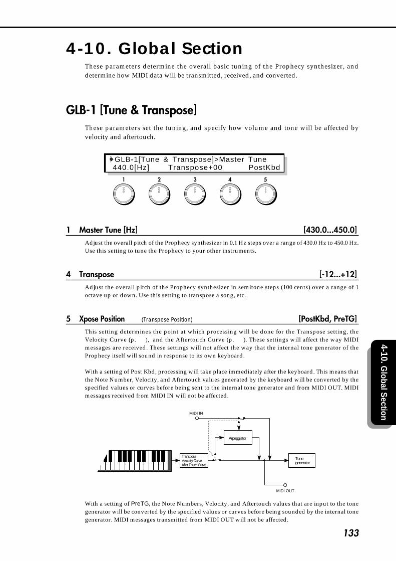
133
4-10. Global S
ection
4-10. Global SectionThese parameters determine the overall basic tuning of the Prophecy synthesizer, anddetermine how MIDI data will be transmitted, received, and converted.
GLB-1 [Tune & Transpose]These parameters set the tuning, and specify how volume and tone will be affected byvelocity and aftertouch.
1 Master Tune [Hz] [430.0...450.0]Adjust the overall pitch of the Prophecy synthesizer in 0.1 Hz steps over a range of 430.0 Hz to 450.0 Hz.Use this setting to tune the Prophecy to your other instruments.
4 Transpose [-12...+12]Adjust the overall pitch of the Prophecy synthesizer in semitone steps (100 cents) over a range of 1octave up or down. Use this setting to transpose a song, etc.
5 Xpose Position (Transpose Position) [PostKbd, PreTG]This setting determines the point at which processing will be done for the Transpose setting, theVelocity Curve (p.134), and the Aftertouch Curve (p.134). These settings will affect the way MIDImessages are received. These settings will not affect the way that the internal tone generator of theProphecy itself will sound in response to its own keyboard.
With a setting of Post Kbd, processing will take place immediately after the keyboard. This means thatthe Note Number, Velocity, and Aftertouch values generated by the keyboard will be converted by thespecified values or curves before being sent to the internal tone generator and from MIDI OUT. MIDImessages received from MIDI IN will not be affected.
Tonegenerator
MIDI OUT
MIDI IN
TransposeVeloc ity CurveAfter Touch Curve
Arpeggiator
With a setting of PreTG, the Note Numbers, Velocity, and Aftertouch values that are input to the tonegenerator will be converted by the specified values or curves before being sounded by the internal tonegenerator. MIDI messages transmitted from MIDI OUT will not be affected.
1 2 3 4 5
GLB-1[Tune & Transpose]>Master Tune 440.0[Hz] Transpose+00 PostKbd

134
Tonegenerator
MIDI OUT
TransposeVeloc ity CurveAfter Touch Curve
MIDI IN
Arpeggiator
GLB-2 [Curve & Effects]Make settings for velocity, aftertouch sensitivity, and reverb/delay bypass.
1 Velocity Curve [1...8]Select one of 8 types of curve by which velocity (keyboard playing dynamics) will cause changes involume or tone.This setting will be affected by the Transpose Point (p.133).
Vel. Curve1: Significant differences will appear only for
strongly played notes2: :3: :4: A normal curve5: :6: Significant differences will appear even
for moderately strong notes7: Moderately played notes will have little
difference, and the effect will be fairly even8: Moderately played notes will have little
difference, and the effect will be fairly even(flatter than 7)
Since curves 7 and 8 produce little change for notes of moderate strength, they are suitable for whenyou do not need velocity or for when you want notes to have an even strength. However control will bemore difficult, since softly played notes will have wider variations.
2 AfterTouchCurve [1...8]Select one of 8 types of curve by which aftertouch (the pressure that you apply to the keyboard afterplaying a note) will affect volume or tone.This setting will be affected by the Transpose Point (p.133).
After Touch Curve1: Significant effect will appear only if you press fairly strongly2: :
1 2 3 4 5
45
(Strength)MIDI Velocity
pppMIN (1)
Velocity
MAX(127)
3
8 7 62
1
fff
1 127
GLB-2[Curve & Ef fects]>Veloci ty CurveVelCrv#1 ATCrv#1 DlyRev:ON
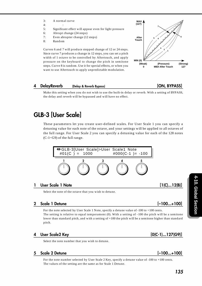
135
4-10. Global S
ection
3: A normal curve4: :5: Significant effect will appear even for light pressure6: Abrupt change (24 steps)7: Even abrupter change (12 steps)8: Random
Curves 6 and 7 will produce stepped change of 12 or 24 steps.Since curve 7 produces a change in 12 steps, you can set a pitchwidth of 1 octave to be controlled by Aftertouch, and applypressure on the keyboard to change the pitch in semitonesteps. Curve 8 is random. Use it for special effects, or when youwant to use Aftertouch to apply unpredictable modulation.
4 DelayReverb (Delay & Reverb Bypass) [ON, BYPASS]Make this setting when you do not wish to use the built-in delay or reverb. With a setting of BYPASS,the delay and reverb will be bypassed and will have no effect.
GLB-3 [User Scale]These parameters let you create user-defined scales. For User Scale 1 you can specify adetuning value for each note of the octave, and your settings will be applied to all octaves ofthe full range. For User Scale 2 you can specify a detuning value for each of the 128 notes(C-1~G9) of the full range.
1 User Scale 1 Note [1(C)...12(B)]Select the note of the octave that you wish to detune.
2 Scale 1 Detune [–100...+100]For the note selected by User Scale 1 Note, specify a detune value of -100 to +100 cents.The setting is relative to equal temperament (0). With a setting of –100 the pitch will be a semitonelower than standard pitch, and with a setting of +100 the pitch will be a semitone higher than standardpitch.
4 User Scale2 Key [0(C-1)...127(G9)]Select the note number that you wish to detune.
5 Scale 2 Detune [–100...+100]For the note number selected by User Scale 2 Key, specify a detune value of -100 to +100 cents.The values of the setting are the same as for Scale 1 Detune.
(Pressure)MIDI After Touch
(Strong)127
AfterTouch
(Weak)0
6
7
MIN (0)
MAX(127)
45
31
2
1 2 3 4 5
GLB-3[User Scale]>User Scale1 Note#01(C ) = 1000 #000(C-1 )= -100
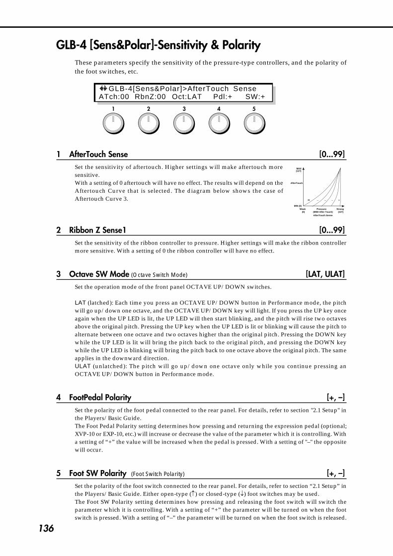
136
GLB-4 [Sens&Polar]-Sensitivity & PolarityThese parameters specify the sensitivity of the pressure-type controllers, and the polarity ofthe foot switches, etc.
1 AfterTouch Sense [0...99]Set the sensitivity of aftertouch. Higher settings will make aftertouch moresensitive.With a setting of 0 aftertouch will have no effect. The results will depend on theAftertouch Curve that is selected. The diagram below shows the case ofAftertouch Curve 3.
2 Ribbon Z Sense1 [0...99]Set the sensitivity of the ribbon controller to pressure. Higher settings will make the ribbon controllermore sensitive. With a setting of 0 the ribbon controller will have no effect.
3 Octave SW Mode (Octave Switch Mode) [LAT, ULAT]Set the operation mode of the front panel OCTAVE UP/DOWN switches.
LAT (latched): Each time you press an OCTAVE UP/DOWN button in Performance mode, the pitchwill go up/down one octave, and the OCTAVE UP/DOWN key will light. If you press the UP key onceagain when the UP LED is lit, the UP LED will then start blinking, and the pitch will rise two octavesabove the original pitch. Pressing the UP key when the UP LED is lit or blinking will cause the pitch toalternate between one octave and two octaves higher than the original pitch. Pressing the DOWN keywhile the UP LED is lit will bring the pitch back to the original pitch, and pressing the DOWN keywhile the UP LED is blinking will bring the pitch back to one octave above the original pitch. The sameapplies in the downward direction.ULAT (unlatched): The pitch will go up/down one octave only while you continue pressing anOCTAVE UP/DOWN button in Performance mode.
4 FootPedal Polarity [+, –]Set the polarity of the foot pedal connected to the rear panel. For details, refer to section "2.1 Setup" inthe Players/Basic Guide.The Foot Pedal Polarity setting determines how pressing and returning the expression pedal (optional;XVP-10 or EXP-10, etc.) will increase or decrease the value of the parameter which it is controlling. Witha setting of “+” the value will be increased when the pedal is pressed. With a setting of "–" the oppositewill occur.
5 Foot SW Polarity (Foot Switch Polarity) [+, –]Set the polarity of the foot switch connected to the rear panel. For details, refer to section “2.1 Setup” inthe Players/Basic Guide. Either open-type (↑) or closed-type (↓) foot switches may be used.The Foot SW Polarity setting determines how pressing and releasing the foot switch will switch theparameter which it is controlling. With a setting of “+” the parameter will be turned on when the footswitch is pressed. With a setting of “–” the parameter will be turned on when the foot switch is released.
1 2 3 4 5
GLB-4[Sens&Polar]>AfterTouch SenseATch:00 RbnZ:00 Oct:LAT Pdl:+ SW:+
Pressure(MIDI After Touch)
Strong(127)
AfterTouch
Weak(0)
MIN (0)
MAX(127)
99 ... ...... 1
AfterTouch Sense

137
4-10. Global S
ection
GLB-5 [Knob Controller Assign]These settings assign the message that each knob will transmit from MIDI OUT; Pitch Bender,Aftertouch, or Control Change etc. In Performance mode, the five knobs will always functionas controllers.
1 Knob1 [OFF, PBender (+/–, +, –), ATouch, CChg#00...95]
2 Knob2 [OFF, PBender (+/–, +, –), ATouch, CChg#00...95]
3 Knob3 [OFF, PBender (+/–, +, –), ATouch, CChg#00...95]
4 Knob4 [OFF, PBender (+/–, +, –), ATouch, CChg#00...95]
5 Knob5 [OFF, PBender (+/–, +, –), ATouch, CChg#00...95]Select the knot (1~5) to which you want to assign a controller function.For the knob selected by Knob Number, specify one of 99 controller functions for that knob to perform.(Refer to 6.3 Modulation Source List.)
GLB-6 [Arpeggio Controller]Select the controller that will modify the velocity and gate time of the arpeggio notes.
2 Velocity [OFF, PBender, ATouch, CChg#00...95]Select the controller that will modify the velocity of the arpeggio notes when an arpeggio is beingplayed.The depth and direction of the change is specified for each pattern in Pattern Define mode page 2[Velocity Param] Ctrl Intensity.
4 Gate [OFF, PBender, ATouch, CChg#00...95]Select the controller that will modify the gate time of the arpeggio notes when an arpeggio is being played.The depth and direction of the change is specified for each pattern in Pattern Define mode page 3 [GateParam] Ctrl Intensity.
1 2 3 4 5
GLB-5[Knob Control ler Assign]>Knob1CChg#19 CChg#20 CChg#21 CChg#22 CChg#23
1 2 3 4 5
GLB-6 [A rpegg ioX Con t ro l l e r ]>Ve loc i t y Vel:CChg#24XXXGate:CChg#25

138
GLB-7 [EC5 Function]When an optional EC5 is connected, these parameters specify the function that is assigned toeach pedal.For details on connections, refer to the Players/Basic Guide section “2.1 Setup”.
1 SW-A (Switch A) [OFF...Wh3Hold]
2 SW-B (Switch B) [OFF...Wh3Hold]
3 SW-C (Switch C) [OFF...Wh3Hold]
4 SW-D (Switch D) [OFF...Wh3Hold]
5 SW-E (Switch E) [OFF...Wh3Hold]For each pedal, select one of the following 14 functions.
0 Off No function1 Sustain OFF/ON (Sustain) Sustain pedal2 Program Up (Prog-Up) Select the next program3 Program Down (Prg-Dwn) Select the previous program4 Octave Up (Oct-Up) 1 octave up5 Octave Down (Oct-Dwn) 1 octave down6 Portamento OFF/ON (Portmnt) Portamento on/off7 Distortion OFF/ON (Dist-SW) Distortion on/off8 Wah OFF/ON (Wah-SW) Wah on/off9 Delay OFF/ON (Dly-SW) Chorus on/off10 Chorus OFF/ON (Cho-SW) Delay on/off11 Reverb OFF/ON (Rev-SW) Reverb on/off12 Arpeggio OFF/ON (Arpg-SW) Arpeggiator function on/off13 Wheel 3 Hold OFF/ON (Wh3Hold) Wheel 3 Hold on/off
1 2 3 4 5
GLB-7[EC5 Function ]>SW-A OFF OFF OFF OFF OFF

139
4-10. Global S
ection
GLB-8 [MIDI]These parameters are MIDI-related settings.
1 Global Channel [1..16]This sets the Global MIDI channel.When musical data or program changes etc. are transmitted from the Prophecy via MIDI, or whentransmitting/receiving System Exclusive messages, the Global MIDI Channel of the Prophecy must beset to match the channel of the other MIDI instrument.
2 Local (Local Control) [ON, OFF]When this parameter is set OFF, the keyboard/controller section of the Prophecy will be disconnectedfrom the tone generator. However the keyboard/controller section will continue to transmit data fromMIDI OUT.When using a sequencer etc. to play the Prophecy, turn this parameter OFF to prevent the unintendeddual triggering that would be caused by the “echo back” from the sequencer (i.e., a situation in whichnote messages sent by the Prophecy to the sequencer are retransmitted back to the Prophecy). Fornormal use, leave this parameter ON.
3 Omni [ON, OFF]When this parameter is set OFF, MIDI transmission and reception will take place on the channelspecified by the Global Channel setting.When this parameter is turned ON, transmission will take place on the Global Channel, but receptionwill take place on any channel, regardless of the Global Channel setting.
5 Clock Source [INTERNAL, EXTERNAL]When synchronizing other MIDI devices (external sequencers, drum machines, etc.) to the arpeggio ofthe Prophecy (i.e., when the Prophecy is the master), set the Clock Source to INTERNAL. This willcause the Prophecy's arpeggiator to operate with its own clock, and it will transmit MIDI Clockmessages at the tempo specified by the arpeggio Speed setting.When synchronizing the arpeggiator of the Prophecy to an external MIDI device, set the Clock Sourceto EXTERNAL. This will cause the arpeggiator tempo to be controlled by MIDI Clock messagesreceived from the external device.
GLB-9 [MIDI Pitch Bend]These parameters specify how Pitch Bend messages are transmitted and received, andwhether or not incoming Pitch Bend messages are converted before being passed to the tonegenerator of the Prophecy.
1 2 3 4 5
GLB-8[MIDI]>Global ChannelG.Ch#01 Local:ON Omni:OFF Clk:INTERNAL
1 2 3 4 5
GLB-9[MIDI Pitch Bend]>TransmitXmt:OFF Rcv:ENABLE PBender Ret:OFF
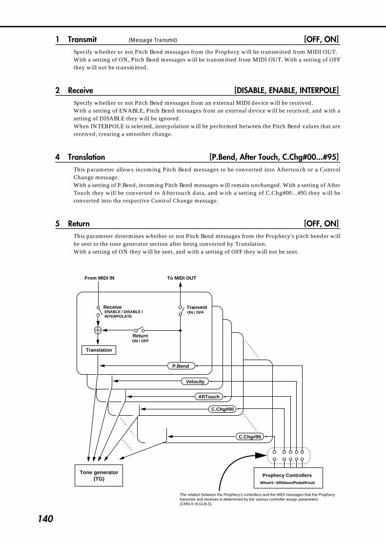
140
1 Transmit (Message Transmit) [OFF, ON]Specify whether or not Pitch Bend messages from the Prophecy will be transmitted from MIDI OUT.With a setting of ON, Pitch Bend messages will be transmitted from MIDI OUT. With a setting of OFFthey will not be transmitted.
2 Receive [DISABLE, ENABLE, INTERPOLE]Specify whether or not Pitch Bend messages from an external MIDI device will be received.With a setting of ENABLE, Pitch Bend messages from an external device will be received, and with asetting of DISABLE they will be ignored.When INTERPOLE is selected, interpolation will be performed between the Pitch Bend values that arereceived, creating a smoother change.
4 Translation [P.Bend, After Touch, C.Chg#00...#95]This parameter allows incoming Pitch Bend messages to be converted into Aftertouch or a ControlChange message.With a setting of P.Bend, incoming Pitch Bend messages will remain unchanged. With a setting of AfterTouch they will be converted to Aftertouch data, and with a setting of C.Chg#00…#95 they will beconverted into the respective Control Change message.
5 Return [OFF, ON]This parameter determines whether or not Pitch Bend messages from the Prophecy's pitch bender willbe sent to the tone generator section after being converted by Translation.With a setting of ON they will be sent, and with a setting of OFF they will not be sent.
Velocity
AftTouch
C.Chg#00
C.Chg#95
P.Bend
Receive Transmit
Return
Translation
音源部�(TG)
From MIDI IN To MIDI OUT
ENABLE / DISABLE /INTERPOLATE
ON / OFF
ON / OFF
The relation between the Prophecy's controllers and the MIDI messages that the Prophecytransmits and receives is determined by the various controller assign parameters(CMN-5~8,GLB-5).
Prophecy ControllersWheel1~3/Ribbon/Pedal/Knob
Tone generator(TG)

141
4-10. Global S
ection
GLB-10 [MIDI After Touch]These parameters specify how Aftertouch messages are transmitted and received, and howincoming Aftertouch messages are converted before being passed to the tone generator of theProphecy.
1 Transmit (Message Transmit) [OFF, ON]Specify whether or not Aftertouch messages from the Prophecy will be transmitted from MIDI OUT.With a setting of ON, Aftertouch messages will be transmitted from MIDI OUT. With a setting of OFFthey will not be transmitted.
2 Receive [DISABLE, ENABLE, INTERPOLE]Specify whether or not Aftertouch messages from an external MIDI device will be received.With a setting of ENABLE, Aftertouch messages from an external device will be received, and with asetting of DISABLE they will be ignored.When INTERPOLE is selected, interpolation will be performed between the Aftertouch values that arereceived, creating a smoother change.
4 Translation [P.Bend, After Touch, C.Chg#00...#95]This parameter allows incoming Aftertouch messages to be converted into Pitch Bend or ControlChange messages.With a setting of After Touch, incoming Aftertouch messages will remain unchanged. With a setting ofP.Bend they will be converted to Pitch Bend data, and with a setting of C.Chg#00…#95 they will beconverted into the respective Control Change message.
5 Return [OFF, ON]This parameter determines whether or not Aftertouch messages from the Prophecy's keyboard will besent to the tone generator section after being converted by Translation.With a setting of ON they will be sent, and with a setting of OFF they will not be sent.
Refer to the diagram on p.140.
1 2 3 4 5
GLB-10[MIDI After Touch]>TransmitXmt:OFF Rcv:ENABLE PBender Ret:OFF

142
GLB-11 [MIDI Control Change]These parameters specify how specific Control Change messages are transmitted andreceived, and how incoming Control Change messages are converted before being passed tothe tone generator of the Prophecy.
1 Control No (Control Number) [0...95]Select the Control Change number for which you wish to make settings.
2 Transmit (Message Transmit) [OFF, ON]Specify whether or not the Control Change message specified by Control Number will be transmittedby the Prophecy from MIDI OUT.With a setting of ON, Control Change messages of the specified number will be transmitted from MIDIOUT. With a setting of OFF they will not be transmitted.
3 Receive [DSBL, ENBL, INTP]Specify whether or not Control Change messages of the specified number will be received from anexternal MIDI device. With a setting of ENBL, Control Change messages of the specified number froman external device will be received, and with a setting of DSBL they will be ignored. When INTP isselected, interpolation will be performed between the data that is received, creating a smoother change.
4 Translation [P.Bend, After Touch, C.Chg#00...#95]This parameter allows incoming Control Change messages of the specified control number to beconverted into another type of message (Pitch Bend, Aftertouch, or a Control Change message ofanother number).Incoming Control Change messages of the specified number will be converted into the type of data thatyou specify here.
5 Return [OFF, ON]This parameter determines whether or not Control Change messages from the Prophecy's pitch benderwill be sent to the tone generator section after being converted by Translation.With a setting of ON they will be sent, and with a setting of OFF they will not be sent.
Refer to the diagram on p.140.
1 2 3 4 5
GLB-11[MIDI ControlChange]>Control No.Ctl#00 Xmt:OFF Rcv:ENBL PBender Ret:OFF

143
4-10. Global S
ection
1 2 3 4 5
1 2 3 4 5
GLB-13[Prog Bank Select Map]>BankBank-A LSB:--- MSB:---
GLB-12 [MIDI Program Change]These parameters determine whether or not Program Change messages will be transmittedand received by the Prophecy.
1 Transmit [OFF, ON]Specify whether or not MIDI Program Change messages will be transmitted from the Prophecy.With a setting of OFF they will not be transmitted, and with a setting of ON they will be transmitted.If this is ON, selecting a program on the Prophecy will cause a Program Change message to betransmitted on the Global MIDI channel (page GLB-8 Global Channel).
3 Receive [OFF, ON]Specify whether or not MIDI Program Change messages will be received by the Prophecy.With a setting of OFF they will not be received, and with a setting of ON they will be received.If this is ON and the Omni setting (page GLB-8 Omni) is OFF, an incoming Program Change messagewhose channel matches the Global MIDI channel will change the program of the Prophecy. If Omni isON, messages of any channel will change the program.
GLB-13 [Prog Bank Select Map]Here you can specify the MIDI Bank Select messages that will correspond to program banksA, B, and C.
1 Bank [A, B, C]Select the program bank of the Prophecy for which you wish to specify a Bank Select number.
2 LSB [---, 000...127]Specify the LSB of the MIDI Bank Select message that will correspond to the above-selected programbank of the Prophecy.
3 MSB [---, 000...127]Specify the MSB of the MIDI Bank Select message that will correspond to the above-selected programbank of the Prophecy.
GLB-12[MIDI Program Change]>TransmitXmt:OFF Rcv:OFF
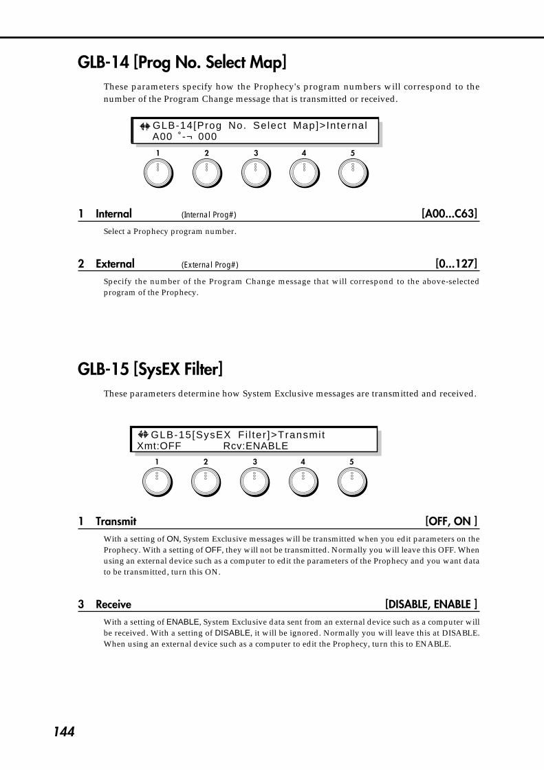
144
GLB-14 [Prog No. Select Map]These parameters specify how the Prophecy's program numbers will correspond to thenumber of the Program Change message that is transmitted or received.
1 Internal (Internal Prog#) [A00...C63]Select a Prophecy program number.
2 External (External Prog#) [0...127]Specify the number of the Program Change message that will correspond to the above-selectedprogram of the Prophecy.
GLB-15 [SysEX Filter]These parameters determine how System Exclusive messages are transmitted and received.
1 Transmit [OFF, ON ]With a setting of ON, System Exclusive messages will be transmitted when you edit parameters on theProphecy. With a setting of OFF, they will not be transmitted. Normally you will leave this OFF. Whenusing an external device such as a computer to edit the parameters of the Prophecy and you want datato be transmitted, turn this ON.
3 Receive [DISABLE, ENABLE ]With a setting of ENABLE, System Exclusive data sent from an external device such as a computer willbe received. With a setting of DISABLE, it will be ignored. Normally you will leave this at DISABLE.When using an external device such as a computer to edit the Prophecy, turn this to ENABLE.
1 2 3 4 5
1 2 3 4 5
GLB-15[SysEX Fi l ter ]>TransmitXmt:OFF Rcv:ENABLE
GLB-14[Prog No. Select Map]>Internal A00 ˚-¬ 000
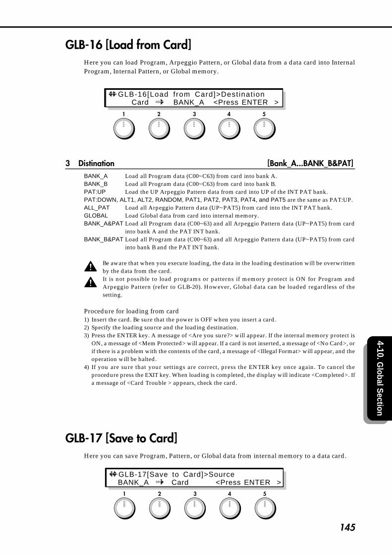
145
4-10. Global S
ection
GLB-16 [Load from Card]Here you can load Program, Arpeggio Pattern, or Global data from a data card into InternalProgram, Internal Pattern, or Global memory.
3 Distination [Bank_A...BANK_B&PAT]BANK_A Load all Program data (C00~C63) from card into bank A.BANK_B Load all Program data (C00~C63) from card into bank B.PAT:UP Load the UP Arpeggio Pattern data from card into UP of the INT PAT bank.PAT:DOWN, ALT1, ALT2, RANDOM, PAT1, PAT2, PAT3, PAT4, and PAT5 are the same as PAT:UP.ALL_PAT Load all Arpeggio Pattern data (UP~PAT5) from card into the INT PAT bank.GLOBAL Load Global data from card into internal memory.BANK_A&PAT Load all Program data (C00~63) and all Arpeggio Pattern data (UP~PAT5) from card
into bank A and the PAT INT bank.BANK_B&PAT Load all Program data (C00~63) and all Arpeggio Pattern data (UP~PAT5) from card
into bank B and the PAT INT bank.
Be aware that when you execute loading, the data in the loading destination will be overwrittenby the data from the card.It is not possible to load programs or patterns if memory protect is ON for Program andArpeggio Pattern (refer to GLB-20). However, Global data can be loaded regardless of thesetting.
Procedure for loading from card1) Insert the card. Be sure that the power is OFF when you insert a card.2) Specify the loading source and the loading destination.3) Press the ENTER key. A message of <Are you sure?> will appear. If the internal memory protect is
ON, a message of <Mem Protected> will appear. If a card is not inserted, a message of <No Card>, orif there is a problem with the contents of the card, a message of <Illegal Format> will appear, and theoperation will be halted.
4) If you are sure that your settings are correct, press the ENTER key once again. To cancel theprocedure press the EXIT key. When loading is completed, the display will indicate <Completed>. Ifa message of <Card Trouble > appears, check the card.
GLB-17 [Save to Card]Here you can save Program, Pattern, or Global data from internal memory to a data card.
1 2 3 4 5
1 2 3 4 5
GLB-16[Load from Card]>Dest inat ion Card BANK_A <Press ENTER >
GLB-17[Save to Card]>Source BANK_A Card <Press ENTER >
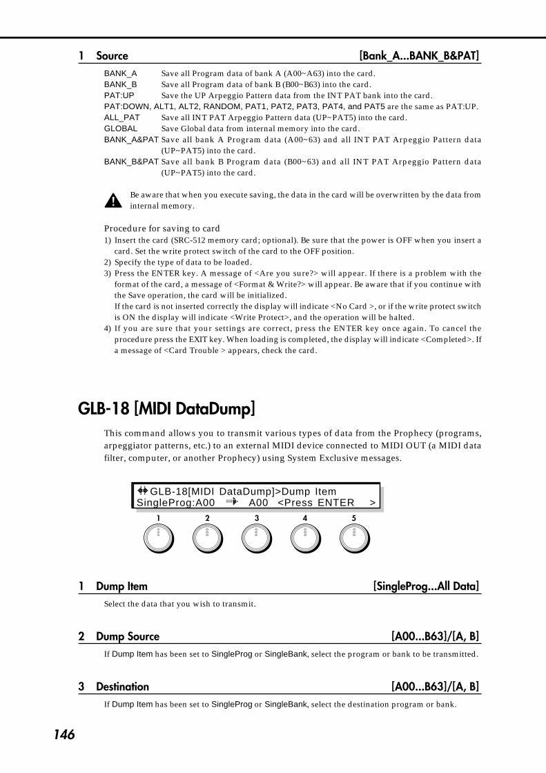
146
1 Source [Bank_A...BANK_B&PAT]BANK_A Save all Program data of bank A (A00~A63) into the card.BANK_B Save all Program data of bank B (B00~B63) into the card.PAT:UP Save the UP Arpeggio Pattern data from the INT PAT bank into the card.PAT:DOWN, ALT1, ALT2, RANDOM, PAT1, PAT2, PAT3, PAT4, and PAT5 are the same as PAT:UP.ALL_PAT Save all INT PAT Arpeggio Pattern data (UP~PAT5) into the card.GLOBAL Save Global data from internal memory into the card.BANK_A&PAT Save all bank A Program data (A00~63) and all INT PAT Arpeggio Pattern data
(UP~PAT5) into the card.BANK_B&PAT Save all bank B Program data (B00~63) and all INT PAT Arpeggio Pattern data
(UP~PAT5) into the card.
Be aware that when you execute saving, the data in the card will be overwritten by the data frominternal memory.
Procedure for saving to card1) Insert the card (SRC-512 memory card; optional). Be sure that the power is OFF when you insert a
card. Set the write protect switch of the card to the OFF position.2) Specify the type of data to be loaded.3) Press the ENTER key. A message of <Are you sure?> will appear. If there is a problem with the
format of the card, a message of <Format & Write?> will appear. Be aware that if you continue withthe Save operation, the card will be initialized.If the card is not inserted correctly the display will indicate <No Card >, or if the write protect switchis ON the display will indicate <Write Protect>, and the operation will be halted.
4) If you are sure that your settings are correct, press the ENTER key once again. To cancel theprocedure press the EXIT key. When loading is completed, the display will indicate <Completed>. Ifa message of <Card Trouble > appears, check the card.
GLB-18 [MIDI DataDump]This command allows you to transmit various types of data from the Prophecy (programs,arpeggiator patterns, etc.) to an external MIDI device connected to MIDI OUT (a MIDI datafilter, computer, or another Prophecy) using System Exclusive messages.
1 Dump Item [SingleProg...All Data]Select the data that you wish to transmit.
2 Dump Source [A00...B63]/[A, B]If Dump Item has been set to SingleProg or SingleBank, select the program or bank to be transmitted.
3 Destination [A00...B63]/[A, B]If Dump Item has been set to SingleProg or SingleBank, select the destination program or bank.
1 2 3 4 5
GLB-18[MIDI DataDump]>Dump ItemSingleProg:A00 A00 <Press ENTERXX>
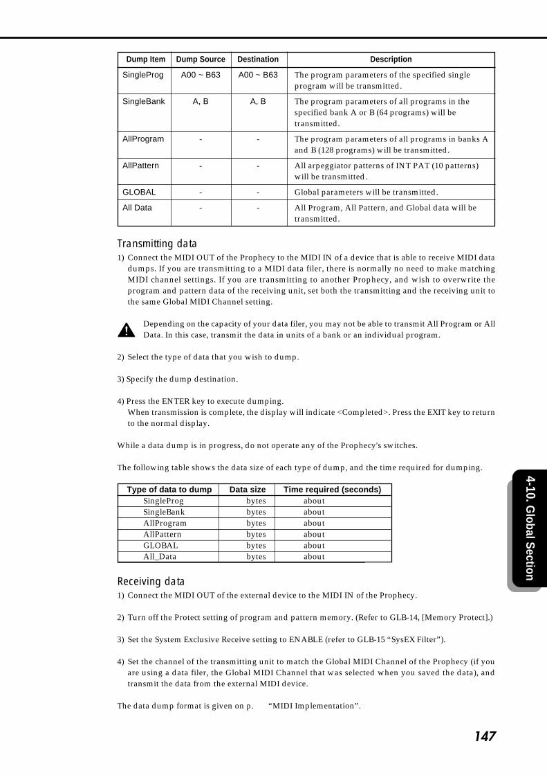
147
4-10. Global S
ection
Dump Item Dump Source Destination Description
SingleProg A00 ~ B63 A00 ~ B63 The program parameters of the specified singleprogram will be transmitted.
SingleBank A, B A, B The program parameters of all programs in thespecified bank A or B (64 programs) will betransmitted.
AllProgram - - The program parameters of all programs in banks Aand B (128 programs) will be transmitted.
AllPattern - - All arpeggiator patterns of INT PAT (10 patterns)will be transmitted.
GLOBAL - - Global parameters will be transmitted.
All Data - - All Program, All Pattern, and Global data will betransmitted.
Transmitting data1) Connect the MIDI OUT of the Prophecy to the MIDI IN of a device that is able to receive MIDI data
dumps. If you are transmitting to a MIDI data filer, there is normally no need to make matchingMIDI channel settings. If you are transmitting to another Prophecy, and wish to overwrite theprogram and pattern data of the receiving unit, set both the transmitting and the receiving unit tothe same Global MIDI Channel setting.
Depending on the capacity of your data filer, you may not be able to transmit All Program or AllData. In this case, transmit the data in units of a bank or an individual program.
2) Select the type of data that you wish to dump.
3) Specify the dump destination.
4) Press the ENTER key to execute dumping.When transmission is complete, the display will indicate <Completed>. Press the EXIT key to returnto the normal display.
While a data dump is in progress, do not operate any of the Prophecy's switches.
The following table shows the data size of each type of dump, and the time required for dumping.
Type of data to dump Data size Time required (seconds)SingleProg 621bytes about 0.4SingleBank 39141bytes about 13AllProgram 78272bytes about 25.2AllPattern 1471bytes about 1GLOBAL 663bytes about 0.5All_Data 80390bytes about 26.1
Receiving data1) Connect the MIDI OUT of the external device to the MIDI IN of the Prophecy.
2) Turn off the Protect setting of program and pattern memory. (Refer to GLB-14, [Memory Protect].)
3) Set the System Exclusive Receive setting to ENABLE (refer to GLB-15 “SysEX Filter”).
4) Set the channel of the transmitting unit to match the Global MIDI Channel of the Prophecy (if youare using a data filer, the Global MIDI Channel that was selected when you saved the data), andtransmit the data from the external MIDI device.
The data dump format is given on p.161 “MIDI Implementation”.
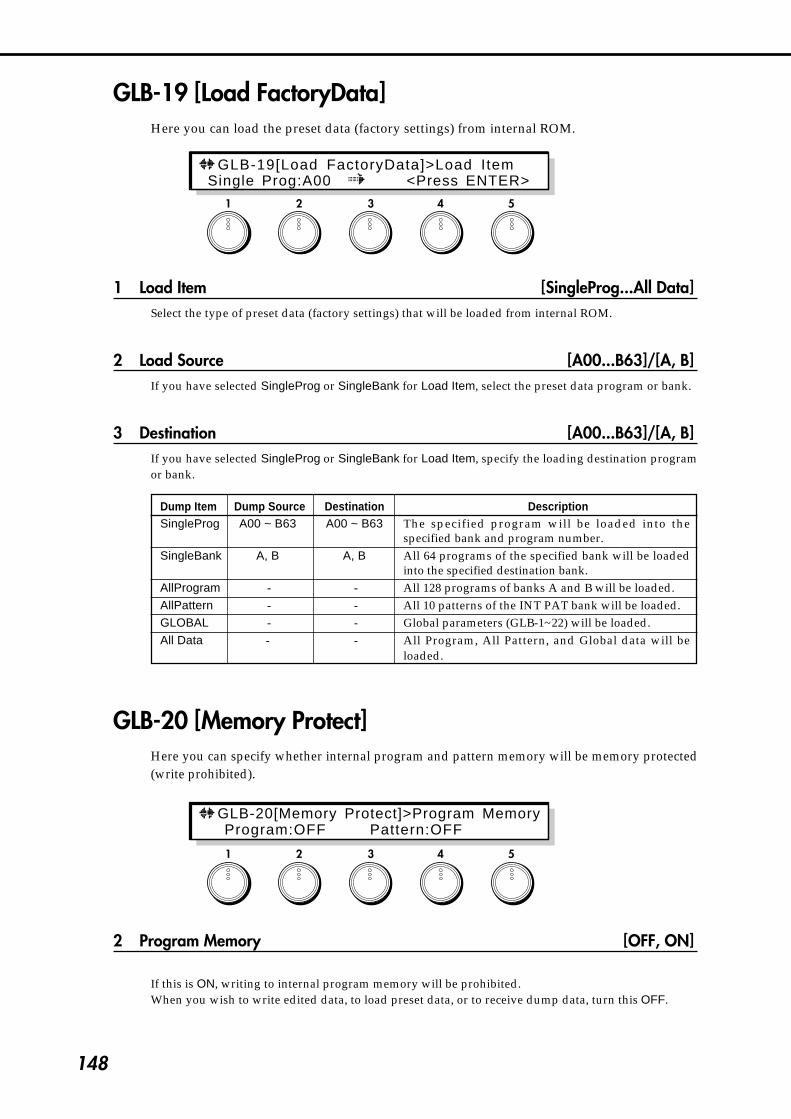
148
GLB-19 [Load FactoryData]Here you can load the preset data (factory settings) from internal ROM.
1 Load Item [SingleProg...All Data]Select the type of preset data (factory settings) that will be loaded from internal ROM.
2 Load Source [A00...B63]/[A, B]If you have selected SingleProg or SingleBank for Load Item, select the preset data program or bank.
3 Destination [A00...B63]/[A, B]If you have selected SingleProg or SingleBank for Load Item, specify the loading destination programor bank.
Dump Item Dump Source Destination DescriptionSingleProg A00 ~ B63 A00 ~ B63 The specified program will be loaded into the
specified bank and program number.SingleBank A, B A, B All 64 programs of the specified bank will be loaded
into the specified destination bank.AllProgram - - All 128 programs of banks A and B will be loaded.AllPattern - - All 10 patterns of the INT PAT bank will be loaded.GLOBAL - - Global parameters (GLB-1~22) will be loaded.All Data - - All Program, All Pattern, and Global data will be
loaded.
GLB-20 [Memory Protect]Here you can specify whether internal program and pattern memory will be memory protected(write prohibited).
2 Program Memory [OFF, ON]
If this is ON, writing to internal program memory will be prohibited.When you wish to write edited data, to load preset data, or to receive dump data, turn this OFF.
1 2 3 4 5
1 2 3 4 5
GLB-19[Load FactoryData]>Load Item Single Prog:A00 <Press ENTER>
GLB-20[Memory Protect]>Program Memory Program:OFF Pattern:OFF

149
4-10. Global S
ection
4 Pattern Memory [OFF, ON]If this is ON, writing to internal pattern memory will be prohibited.When you wish to write edited data, to load preset data, or to receive dump data, turn this OFF.
GLB-21 [Page Memory & 10’s Hold]Here you can specify whether or not to use the Page Memory function and the 10's Holdfunction.
2 Page Memory [OFF, ON]If this is ON, the program (bank and number, etc.) that was last-selected when the power was turned offwill be selected when you turn the power on. Also when you move to each section of other modes, thepage (parameter) last-selected in that section will be selected.If this is OFF, program A00 will be selected when you turn the power on, and when you move to eachmode and section, page 1 will be selected.In either case, as long as the power remains on, the last-selected page (parameter) in each mode orsection will always be selected when you return to that mode or section.
5 10‘s Hold Memory [OFF, ON]When this is ON, if you press a single numeric key and then the ENTER key, the 10's place of thepreviously-selected program number will be held, and the 1's place will be entered by the numeric keyyou pressed.When this is OFF, the 10's place will be fixed at 0, and the numeric key will enter a one-digit number.
GLB-22 [Controller Calibration]Here you can adjust the effective ranges of the wheel 1--3, ribbon controller, aftertouch, andfoot pedal.Make adjustments here if the specified effect no longer occurs when each controller is movedto the upper or lower limit of its range, or if the effect reaches maximum or minimum mid-way through its range. Also be sure to perform these adjustments after you initialize theProphecy.
1 2 3 4 5
G L B - 2 2 [ C o n t r o l l e r C a l i b r a t i o n ] WHEEL1 L˚- * -¬H <Min&Max OK? >
1 2 3 4 5
GLB-21[Page Memory & 10's Hold]PageMemory:OFF 10's Hold:OFF

150
1 (Souce Select) [WHEEL1...Foot_Pdl]Adjust the active range of each controller. For Wheel 1 and Wheel 3, also adjust the width of the “dead”area in the center.WHEEL1: Adjust the active range front⇔ back, and the width of the center area.WHEEL2: Adjust the active range front⇔ back.WHEEL3: Adjust the active range front⇔ back, and the width of the center area.RIBBON_X: Adjust the active range left⇔ right(X).RIBBON_Z: Adjust the active range when the ribbon is pressed.AftTouch: Adjust the active range when the keyboard of the Prophecy is pressed.Foot_Pdl: Adjust the active range when a connected foot pedal is pressed.
Adjustment procedure1) Select the controller whose active range you wish to adjust.2) Move the selected controller as far as it will go. The display will show several (6--8) asterisks "*".3) Press the ENTER key. A message will ask <Are you sure?>4) If you are satisfied with the settings, press the ENTER key once again. If you wish to cancel, press the
EXIT key, and re-do the procedure from step 2.If a controller other than Wheel 1 or Wheel 3 was selected in step 1, the display will indicate<Completed>, and the response of the controller will be adjusted so that the maximum andminimum effect is reached in the area that you specified. If Wheel 1 or Wheel 3 was selected, thedisplay will ask <Center OK? >. Continue the procedure from step 5.If the settings were not appropriate, the display will indicate <Value Mismatch>. Press the EXIT keyand re-try the procedure from step 2.
Adjusting the center range for Wheels 1 and 35) For normal settings, move the wheel slightly in the “dead” area. One or two asterisks “*” will appear
in the display.6) If an “*” appears in an unwanted position, press the EXIT key and try again from step 5.7) Press the ENTER key. The display will ask <Are you sure?>.8) If you are satisfied with the setting, press the ENTER key once again. If you wish to cancel, press the
EXIT key and try again from step 2.
A small amount of dead area will automatically be inserted at the maximum, minimum andcenter of the active area as appropriate for each controller. If you make excessively narrowsettings for the active area, or if the maximum or minimum positions are too close to the center,the display will indicate <Value Mismatch>.
Example: adjusting Wheel 1
5) 2)

151
5.W
RIT
E
1 2 3 4 5
WriteThis operation writes a program into memory.
Programs can be saved in bank A 00~63, bank B 00~63, and if a card is writable, into CARD bank 00~63.
The following settings are written into memory:Performance mode: PE key on/off, knob 1~5 levels, PORTAMENTO key on/offEdit mode Parameters other than Global mode; all parameters in Performance Editor Define.In Edit mode, changes you make to Global section parameters are saved when you change the setting,so there is no need to use the Write procedure.
Pattern Define: 10 arpeggio patterns can be saved in bank INT PAT, but in the same way as for theGlobal section, the data is saved when you modify it, and there is no need to use the Write procedure.
Memory protectIn order to prevent data from inadvertently being overwritten and lost, a memory protect switch isprovided in Global section page GLB-20 [Memory Protect]. If you wish to write data into memory, youmust first turn off this memory protect setting in the Global section.
RenameIf you want to assign a new name to an edited program, specify the name in Common section pageCMN-1 [Program Name]. You can specify a program category in page CMN-2 [Prog Category], andwhen selecting programs in Performance mode you can use the PAGE keys to select programs bycategory.
For details on these procedures, refer to the separate Players/Basic Guide.
5.WRITE
This chapter explains how to write program settings intomemory. You can enter Program Write from any mode bypressing the WRITE key. In Performance mode, you can useWrite to save programs you modified using the PerformanceEditor, or settings for the PE1~4 keys or Portamento on/off,etc. In Edit mode, you can use Write to save the changes youmake to parameters other than Global section parameters.
a00 : [P rophe t i c S teps ! ]>w i l l save as-¬A01:(Prophetic Steps!) <Press ENTER >

152
6.Appendix
6.1 About data cards6.2 About modulation sources6.3 Modulation source List6.4 Performance Editor Assign Parameter List6.5 LFO Wave List6.6 MIDI Implementation6.7 Troubleshooting6.8 Error messages6.9 Other messages
6.1 About data cardsA data card can be inserted into the Prophecy to add programs or arpeggio patterns, or to store yourown original programs or arpeggio patterns.
A RAM card (SRC-512: sold separately) can store programs, arpeggio patterns, and global data that youhave edited. Programs in a RAM card can be edited and written back into the card.
A ROM card (sold separately) also stores programs and arpeggio patterns, but unlike a RAM card,cannot store data that you have edited. Also, it is not possible to directly edit the data in a ROM card, soit must first be copied into internal memory before it can be edited.
Data card handlingInsert the card into the card slot with the card label facing upward.
Be sure that the power is turned OFF before inserting or removing a card. Inserting or removinga card while the Prophecy is producing sound or while an operation is being performed maycause malfunctions.
RAM card write protect switchRAM cards have a Write Protect switch that allows you to keep data from being accidently being erasedor overwritten. When this switch is ON, it is not possible to write data into the RAM card. (The WriteProtect switch is located on the side of the RAM card.)
When you need to write data into the RAM card, set the Write Protect switch to the OFF position.However when the switch is in the OFF position, the battery will run down faster, so leave it in the ONposition when the card is not being used.
Formatting a RAM cardWhen you use the Edit mode Global section page GLB-17 [Save to Card] command to save data to anew RAM card, the card will automatically be formatted. (There is no need for you to format the card.)
If you wish to write individual programs or arpeggio patterns into a RAM card, you must first use pageGLB-17 [Save to Card] to save data and thereby format the card.
RAM card batteryRAM cards contain a battery (CR2016 lithium battery) that preserves the data. If the battery voltagebecomes low, the display will indicate "Battery Low". To replace the battery, refer to the instructionsincluded with the RAM card.
Replacing the RAM card batteryIn order to prevent loss of data stored in a RAM card, we recommend that you replace the battery oncea year. If you store the card in a location of high temperature (above 40 degrees C) the battery will rundown faster. Replace the battery with a CR2016 llithium battery. (Contact a nearby musical instrumentdealer.)

153
6.A
pp
end
ix
If you simply remove the battery from the card when replacing the battery, the data in the card will belost. If you wish to preserve the data that is in the card, insert the card into the Prophecy and replace thebattery with the Prophecy's power turned ON.
6.2 About modulation sourcesSources of control such as an LFO, the pitch bender, or keyboard velocity can be assigned to control theparameters of the oscillator, the filter, and the effects (e.g., Filter Cutoff, or Effect Balance, etc.) Sourcesof control that can be used to control (“modulate”) parameters are known as Modulation Sources. Foreach parameter that can be controlled by a modulation source, there is a Mod.Source setting that allowsyou to select one of the 111 types of modulation sources (refer to 6.3 Modulation Source List) to controlthat parameter.
* How keyboard velocity acts as a Modulation SourceVelocity can act as a modulation source in two ways.
1 If velocity is selected as a modulation source, the change will be centered around the setting of theparameter that is being controlled. (See figure 1.)
2 If the Velocity Control amount can be dedicated to a specific parameter, positive (+) settings willresult in the control parameter value being reached for maximum velocities, and negative (-)settings will result in the control parameter value being reached for minimum velocities. (Seefigure 2.)
0
1 127
+
-
0
1 127
+
-
ベロシティーの値�
パラメータの変化量�
ベロシティーの値�
パラメータの変化量�(図1)� (図2)�
Int=+99
Int=-99
Int=+99
Int=-99
Int= 0 Int= 0
6.3 Modulation Source ListNo Modulation Source Editor Name0 Off Off1 EG1 EG12 EG2 EG23 EG3 EG34 EG4 EG45 Pitch EG PitchEG6 Amp EG AmpEG7 LFO1 LFO18 LFO2 LFO29 LFO3 LFO310 LFO4 LFO411 Portamento Portmnt12 Note No. NoteNo.13 Velocity Veloc14 Pitch Bender PBender15 After Touch ATouch16 Control Change #0 CChg#00. . .. . .. . .111 Control Change #95 CChg#95
(Figure 1)Amount of parameter change
(Figure 2)Amount of parameter change
Velocity value Velocity value
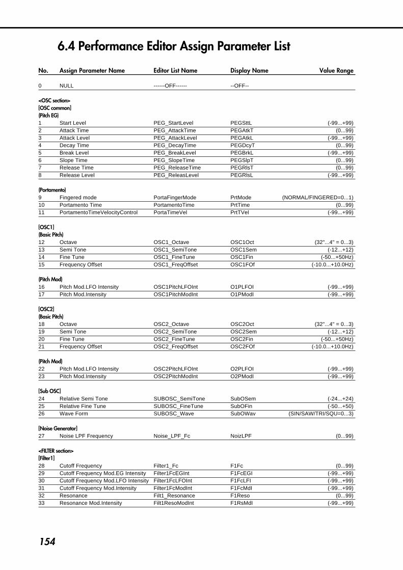
154
6.4 Performance Editor Assign Parameter List
No. Assign Parameter Name Editor List Name Display Name Value Range
0 NULL ------OFF------ --OFF--
<OSC section>[OSC common](Pitch EG)1 Start Level PEG_StartLevel PEGSttL (-99...+99)2 Attack Time PEG_AttackTime PEGAtkT (0...99)3 Attack Level PEG_AttackLevel PEGAtkL (-99...+99)4 Decay Time PEG_DecayTime PEGDcyT (0...99)5 Break Level PEG_BreakLevel PEGBrkL (-99...+99)6 Slope Time PEG_SlopeTime PEGSlpT (0...99)7 Release Time PEG_ReleaseTime PEGRlsT (0...99)8 Release Level PEG_ReleasLevel PEGRlsL (-99...+99)
(Portamento)9 Fingered mode PortaFingerMode PrtMode (NORMAL/FINGERED=0...1)10 Portamento Time PortamentoTime PrtTime (0...99)11 PortamentoTimeVelocityControl PortaTimeVel PrtTVel (-99...+99)
[OSC1](Basic Pitch)12 Octave OSC1_Octave OSC1Oct (32"...4" = 0...3)13 Semi Tone OSC1_SemiTone OSC1Sem (-12...+12)14 Fine Tune OSC1_FineTune OSC1Fin (-50...+50Hz)15 Frequency Offset OSC1_FreqOffset OSC1FOf (-10.0...+10.0Hz)
(Pitch Mod)16 Pitch Mod.LFO Intensity OSC1PitchLFOInt O1PLFOI (-99...+99)17 Pitch Mod.Intensity OSC1PitchModInt O1PModI (-99...+99)
[OSC2](Basic Pitch)18 Octave OSC2_Octave OSC2Oct (32"...4" = 0...3)19 Semi Tone OSC2_SemiTone OSC2Sem (-12...+12)20 Fine Tune OSC2_FineTune OSC2Fin (-50...+50Hz)21 Frequency Offset OSC2_FreqOffset OSC2FOf (-10.0...+10.0Hz)
(Pitch Mod)22 Pitch Mod.LFO Intensity OSC2PitchLFOInt O2PLFOI (-99...+99)23 Pitch Mod.Intensity OSC2PitchModInt O2PModI (-99...+99)
[Sub OSC]24 Relative Semi Tone SUBOSC_SemiTone SubOSem (-24...+24)25 Relative Fine Tune SUBOSC_FineTune SubOFin (-50...+50)26 Wave Form SUBOSC_Wave SubOWav (SIN/SAW/TRI/SQU=0...3)
[Noise Generator]27 Noise LPF Frequency Noise_LPF_Fc NoizLPF (0...99)
<FILTER section>[Filter1]28 Cutoff Frequency Filter1_Fc F1Fc (0...99)29 Cutoff Frequency Mod.EG Intensity Filter1FcEGInt F1FcEGI (-99...+99)30 Cutoff Frequency Mod.LFO Intensity Filter1FcLFOInt F1FcLFI (-99...+99)31 Cutoff Frequency Mod.Intensity Filter1FcModInt F1FcMdI (-99...+99)32 Resonance Filt1_Resonance F1Reso (0...99)33 Resonance Mod.Intensity Filt1ResoModInt F1RsMdI (-99...+99)

155
6.A
pp
end
ix
[Filter2]34 Cutoff Frequency Filter2_Fc F2Fc (0...99)35 Cutoff Frequency Mod.EG Intensity Filter2FcEGInt F2FcEGI (-99...+99)36 Cutoff Frequency Mod.LFO Intensity Filter2FcLFOInt F2FcLFI (-99...+99)37 Cutoff Frequency Mod.Intensity Filter2FcModInt F2FcMdI (-99...+99)38 Resonance Filt2_Resonance F2Reso (0...99)39 Resonance Mod.Intensity Filt2ResoModInt F2RsMdI (-99...+99)
<AMP section>[AMP1]40 Amplitude Amp1_Amplitude Amp1 (0...99)41 Amplitude Mod.Intensity Amp1_ModInt Amp1MdI (-99...+99)
[AMP2]42 Amplitude Amp2_Amplitude Amp2 (0...99)43 Amplitude Mod.Intensity Amp2_ModInt Amp2MdI (-99...+99)
[Amp EG](Amplitude EG)44 Start Level AEG_StartLevel AEGSttL (0...99)45 Attack Time AEG_AttackTime AEGAtkT (0...99)46 Attack Level AEG_AttackLevel AEGAtkL (0...99)47 Decay Time AEG_DecayTime AEGDcyT (0...99)48 Break Level AEG_BreakLevel AEGBrkL (0...99)49 Slope Time AEG_SlopeTime AEGSlpT (0...99)50 Sustain Level AEG_SustanLevel AEGSusL (0...99)51 Release Time AEG_ReleaseTime AEGRlsT (0...99)
(Amplitude EG Velocity Control)52 Level AEG_VelCtlLevel AEGVelL (-99...+99)53 Attack Time AEG_VelAtckTime AEGVAtT (-99...+99)54 Decay Time AEG_VelDcayTime AEGVDcT (-99...+99)55 Slope Time AEG_VelSlopTime AEGVSlT (-99...+99)56 Release Time AEG_VelRlsTime AEGVRlT (-99...+99)
< EFFECT section >[Distortion & Wah](Distortion)57 Gain Distortion_Gain DistGin (0...99)58 Tone Distortion_Tone DistTon (0...99)59 Effect Balance Distortion_Bal DistBal (0...100%)
(Wah)60 Resonance Wah_Resonance WahReso (0...99)61 Effect Balance Wah_Balance WahBal (0...100%)
[Delay/Reverb](Chorus/Flanger)62 Feedback Chorus_Feedback ChoFbk (-99...+99)63 Depth Chorus_Depth ChoDpth (0...99)64 Effect Balance Chorus_Balance ChoBal (0...100%)
(Delay)65 Delay Time Delay_DelayTime DlyTime (0...99)66 Feedback Delay_Feedback DlyFbk (0...99)67 High Damp Delay_HighDamp DlyHD (0...99)68 Effect Balance Delay_Balance DlyBal (0...100%)
(Reverb)69 Reverb Time Reverb_Time RevTime (0...99)70 High Damp Reverb_HighDamp RevHD (0...99)71 Effect Balance Reverb_Balance RevBal (0...100%)
[Panpot & OutputLevel]72 Panpot Panpot Panpot (LEFT...RIGHT = 0...127)

156
<EG section>[EG1](Envelope)73 Start Level EG1_StartLevel EG1SttL (-99...+99)74 Attack Time EG1_AttackTime EG1AtkT (0...99)75 Attack Level EG1_AttackLevel EG1AtkL (-99...+99)76 Decay Time EG1_DecayTime EG1DcyT (0...99)77 Break Level EG1_BreakLevel EG1BrkL (-99...+99)78 Slope Time EG1_SlopeTime EG1SlpT (0...99)79 Sustain Level EG1_SustanLevel EG1SusL (-99...+99)80 Release Time EG1_ReleaseTime EG1RlsT (0...99)81 Release Level EG1_ReleasLevel EG1RlsL (-99...+99)
(Velocity Control)82 Level EG1_VelCtlLevel EG1VCtL (-99...+99)83 Attack Time EG1_VelAtckTime EG1VAtT (-99...+99)84 Decay Time EG1_VelDcayTime EG1VDcT (-99...+99)85 Slope Time EG1_VelSlopTime EG1VSlT (-99...+99)86 Release Time EG1_VelRlsTime EG1VRlT (-99...+99)
[EG2](Envelope)87 Start Level EG2_StartLevel EG2SttL (-99...+99)88 Attack Time EG2_AttackTime EG2AtkT (0...99)89 Attack Level EG2_AttackLevel EG2AtkL (-99...+99)90 Decay Time EG2_DecayTime EG2DcyT (0...99)91 Break Level EG2_BreakLevel EG2BrkL (-99...+99)92 Slope Time EG2_SlopeTime EG2SlpT (0...99)93 Sustain Level EG2_SustanLevel EG2SusL (-99...+99)94 Release Time EG2_ReleaseTime EG2RlsT (0...99)95 Release Level EG2_ReleasLevel EG2RlsL (-99...+99)
(Velocity Control)96 Level EG2_VelCtlLevel EG2VCtL (-99...+99)97 Attack Time EG2_VelAtckTime EG2VAtT (-99...+99)98 Decay Time EG2_VelDcayTime EG2VDcT (-99...+99)99 Slope Time EG2_VelSlopTime EG2VSlT (-99...+99)100 Release Time EG2_VelRlsTime EG2VRlT (-99...+99)
[EG3](Envelope)101 Start Level EG3_StartLevel EG3SttL (-99...+99)102 Attack Time EG3_AttackTime EG3AtkT (0...99)103 Attack Level EG3_AttackLevel EG3AtkL (-99...+99)104 Decay Time EG3_DecayTime EG3DcyT (0...99)105 Break Level EG3_BreakLevel EG3BrkL (-99...+99)106 Slope Time EG3_SlopeTime EG3SlpT (0...99)107 Sustain Level EG3_SustanLevel EG3SusL (-99...+99)108 Release Time EG3_ReleaseTime EG3RlsT (0...99)109 Release Level EG3_ReleasLevel EG3RlsL (-99...+99)
(Velocity Control)110 Level EG3_VelCtlLevel EG3VCtL (-99...+99)111 Attack Time EG3_VelAtckTime EG3VAtT (-99...+99)112 Decay Time EG3_VelDcayTime EG3VDcT (-99...+99)113 Slope Time EG3_VelSlopTime EG3VSlT (-99...+99)114 Release Time EG3_VelRlsTime EG3VRlT (-99...+99)
[EG4](Envelope)115 Start Level EG4_StartLevel EG4SttL (-99...+99)116 Attack Time EG4_AttackTime EG4AtkT (0...99)117 Attack Level EG4_AttackLevel EG4AtkL (-99...+99)118 Decay Time EG4_DecayTime EG4DcyT (0...99)119 Break Level EG4_BreakLevel EG4BrkL (-99...+99)120 Slope Time EG4_SlopeTime EG4SlpT (0...99)
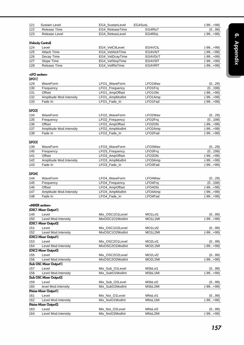
157
6.A
pp
end
ix
121 Sustain Level EG4_SustanLevel EG4SusL (-99...+99)122 Release Time EG4_ReleaseTime EG4RlsT (0...99)123 Release Level EG4_ReleasLevel EG4RlsL (-99...+99)
(Velocity Control)124 Level EG4_VelCtlLevel EG4VCtL (-99...+99)125 Attack Time EG4_VelAtckTime EG4VAtT (-99...+99)126 Decay Time EG4_VelDcayTime EG4VDcT (-99...+99)127 Slope Time EG4_VelSlopTime EG4VSlT (-99...+99)128 Release Time EG4_VelRlsTime EG4VRlT (-99...+99)
<LFO section>[LFO1]129 WaveForm LFO1_WaveForm LFO1Wav (0...29)130 Frequency LFO1_Frequency LFO1Frq (0...199)131 Offset LFO1_AmpOffset LFO1Ofs (-99...+99)132 Amplitude Mod.Intensity LFO1_AmpModInt LFO1Amp (-99...+99)133 Fade In LFO1_Fade_In LFO1Fad (-99...+99)
[LFO2]134 WaveForm LFO2_WaveForm LFO2Wav (0...29)135 Frequency LFO2_Frequency LFO2Frq (0...199)136 Offset LFO2_AmpOffset LFO2Ofs (-99...+99)137 Amplitude Mod.Intensity LFO2_AmpModInt LFO2Amp (-99...+99)138 Fade In LFO2_Fade_In LFO2Fad (-99...+99)
[LFO3]139 WaveForm LFO3_WaveForm LFO3Wav (0...29)140 Frequency LFO3_Frequency LFO3Frq (0...199)141 Offset LFO3_AmpOffset LFO3Ofs (-99...+99)142 Amplitude Mod.Intensity LFO3_AmpModInt LFO3Amp (-99...+99)143 Fade In LFO3_Fade_In LFO3Fad (-99...+99)
[LFO4]144 WaveForm LFO4_WaveForm LFO4Wav (0...29)145 Frequency LFO4_Frequency LFO4Frq (0...199)146 Offset LFO4_AmpOffset LFO4Ofs (-99...+99)147 Amplitude Mod.Intensity LFO4_AmpModInt LFO4Amp (-99...+99)148 Fade In LFO4_Fade_In LFO4Fad (-99...+99)
<MIXER section>(OSC1 Mixer Output1)149 Level Mix_OSC1O1Level MO1Lvl1 (0...99)150 Level Mod.Intensity MixOSC1O1ModInt MO1L1MI (-99...+99)(OSC1 Mixer Output2)151 Level Mix_OSC1O2Level MO1Lvl2 (0...99)152 Level Mod.Intensity MixOSC1O2ModInt MO1L2MI (-99...+99)(OSC2 Mixer Output1)153 Level Mix_OSC2O1Level MO2Lvl1 (0...99)154 Level Mod.Intensity MixOSC2O1ModInt MO2L1MI (-99...+99)(OSC2 Mixer Output2)155 Level Mix_OSC2O2Level MO2Lvl2 (0...99)156 Level Mod.Intensity MixOSC2O2ModInt MO2L2MI (-99...+99)(Sub OSC Mixer Output1)157 Level Mix_Sub_O1Level MSbLvl1 (0...99)158 Level Mod.Intensity Mix_SubO1ModInt MSbL1MI (-99...+99)(Sub OSC Mixer Output2)159 Level Mix_Sub_O2Level MSbLvl2 (0...99)160 level Mod.Intensity Mix_SubO2ModInt MSbL2MI (-99...+99)(Noise Mixer Output1)161 Level Mix_Noi_O1Level MNsLvl1 (0...99)162 Level Mod.Intensity Mix_NoiO1ModInt MNsL1MI (-99...+99)(Noise Mixer Output2)163 Level Mix_Noi_O2Level MNsLvl2 (0...99)164 Level Mod.Intensity Mix_NoiO2ModInt MNsL2MI (-99...+99)
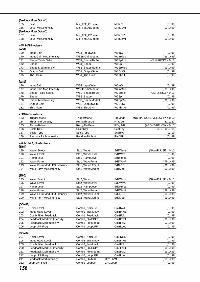
158
(Feedback Mixer Output1)165 Level Mix_Fbk_O1Level MFbLvl1 (0...99)166 Level Mod.Intensity Mix_FbkO1ModInt MFbL1MI (-99...+99)(Feedback Mixer Output2)167 Level Mix_Fbk_O2Level MFbLvl2 (0...99)168 Level Mod.Intensity Mix_FbkO2ModInt MFbL2MI (-99...+99)
< W.SHAPE section >[WS1]169 Input Gain WS1_InputGain W1InG (0...99)170 Input Gain Mod.Intensity WS1InGainModInt W1InMod (-99...+99)171 Shape Table Select WS1_ShapeTblSel W1SpTbl (CLIP/RESO = 0...1)172 Shape WS1_Shape W1Sp (0...99)173 Shape Mod.Intensity WS1_ShapeModInt W1SpMod (-99...+99)174 Output Gain WS1_OutputGain W1OutG (0...99)175 Thru Gain WS1_ThruGain W1ThruG (0...99)
[WS2]176 Input Gain WS2_InputGain W2InG (0...99)177 Input Gain Mod.Intensity WS2InGainModInt W2InMod (-99...+99)178 Shape Table Select WS2_ShapeTblSel W2SpTbl (CLIP/RESO = 0...1)179 Shape WS2_Shape W2Sp (0...99)180 Shape Mod.Intensity WS2_ShapeModInt W2SpMod (-99...+99)181 Output Gain WS2_OutputGain W2OutG (0...99)182 Thru Gain WS2_ThruGain W2ThruG (0...99)
<COMMON section>183 Trigger Mode TriggerMode TrgMode (MULTI/SINGLE/VELOCITY = 0...2)184 Threshold Velocity RetrigThresVel RTrgVel (1...127)185 Above/Below RetrigAbvBelw RTrgA/B (ABOVE/BELOW = 0...1)186 Scale Key ScaleKey ScalKey (C...B = 0...11)187 Scale Type ScaleType ScalTyp (0...10)188 Random Pitch Intensity RandomPitchInt RNDPInt (0...99)
<Multi OSC Synthis Section >[STD1]189 Wave Select Std1_Wave Sd1Wave (SAW/PULSE = 0...1)190 Wave Level Std1_WaveLevel Sd1WavL (0...99)191 Ramp Level Std1_RampLevel Sd1RmpL (0...99)192 Wave Form Std1_WaveForm Sd1WavF (-99...+99)193 Wave Form Mod.LFO Intensity Std1_WaveLFOInt Sd1LFOI (-99...+99)194 wave Form Mod.Intensity Std1_WaveModInt Sd1ModI (-99...+99)
[STD2]195 Wave Select Std2_Wave Sd2Wave (SAW/PULSE = 0...1)196 Wave Level Std2_WaveLevel Sd2WavL (0...99)197 Ramp Level Std2_RampLevel Sd2RmpL (0...99)198 Wave Form Std2_WaveForm Sd2WavF (-99...+99)199 Wave Form Mod.LFO Intensity Std2_WaveLFOInt Sd2LFOI (-99...+99)200 wave Form Mod.Intensity Std2_WaveModInt Sd2ModI (-99...+99)
[COMB1]201 Noise Level Comb1_NoiseLvl Cm1NoiL (0...99)202 Input Wave Level Comb1_InWaveLvl Cm1InWL (0...99)203 Comb Filter Feedback Comb1_Feedback Cm1Fbk (0...99)204 Feedback Mod.EG Intensity Comb1_FbkEGInt Cm1FbEI (-99...+99)205 Feedback Mod.Intensity Comb1_FbkModInt Cm1FbMI (-99...+99)206 Loop LPF Freq Comb1_LoopLPF Cm1Loop (0...99)
[COMB2]207 Noise Level Comb2_NoiseLvl Cm2NoiL (0...99)208 Input Wave Level Comb2_InWaveLvl Cm2InWL (0...99)209 Comb Filter Feedback Comb2_Feedback Cm2Fbk (0...99)200 Feedback Mod.EG Intensity Comb2_FbkEGInt Cm2FbEI (-99...+99)211 Feedback Mod.Intensity Comb2_FbkModInt Cm2FbMI (-99...+99)212 Loop LPF Freq Comb2_LoopLPF Cm2Loop (0...99)211 Feedback Mod.Intensity Comb1_FbkMdI Cm1FbMI (-99...+99)212 Loop LPF Freq Comb1_LoopLP Cm1Loop (0...99)

159
6.A
pp
end
ix
[VPM1](Carrier)213 Carrier Wave VPM1Cr_Wave V1CWav (SIN/SAW/TRI/SQU = 0...3)214 Carrier Level VPM1Cr_Level V1CLvl (0...99)215 Carrier Level Mod.EG Intensity VPM1Cr_LvlEGInt V1CLEGI (-99...+99)216 Carrier Level Mod.Intensity VPM1CrLvlModInt V1CLMdI (-99...+99)217 Wave Shape VPM1_WaveShape V1WvShp (0...99)218 Wave Shape Mod.LFO Intensity VPM1WavShLFOInt V1WSLFI (-99...+99)219 Wave Shape Mod.Intensity VPM1WavShModInt V1WSMdI (-99...+99)220 Feedback VPM1Cr_Feedback V1CFbk (0...99)(modulator)221 Modulator Pitch Mod.Intensity VPM1MdPitModInt V1MPMI (-99...+99)222 Modulator Wave VPM1Md_Wave V1MWav (SIN/SAW/TRI/SQU/OSC2=0...4)223 Modulator Level VPM1Md_Level V1MLvl (0...99)224 Modulator Level Mod.EG Intensity VPM1Md_LvlEGInt V1MLEGI (-99...+99)225 Modulator Level Mod.Intensity VPM1MdLvlModInt V1MLMdI (-99...+99)
[VPM2](Carrier)226 Carrier Wave VPM2Cr_Wave V2CWav (SIN/SAW/TRI/SQU = 0...3)227 Carrier Level VPM2Cr_Level V2CLvl (0...99)228 Carrier Level Mod.EG Intensity VPM2Cr_LvlEGInt V2CLEGI (-99...+99)229 Carrier Level Mod.Intensity VPM2CrLvlModInt V2CLMdI (-99...+99)230 Wave Shape VPM2_WaveShape V2WvShp (0...99)231 Wave Shape Mod.LFO Intensity VPM2WavShLFOInt V2WSLFI (-99...+99)232 Wave Shape Mod.Intensity VPM2WavShModInt V2WSMdI (-99...+99)233 Feedback VPM2Cr_Feedback V2CFbk (0...99)(modulator)234 Modulator Pitch Mod.Intensity VPM2MdPitModInt V2MPMI (-99...+99)235 Modulator Wave VPM2Md_Wave V2MWav (SIN/SAW/TRI/SQU/OSC1=0...4)236 Modulator Level VPM2Md_Level V2MLvl (0...99)237 Modulator Level Mod.EG Intensity VPM2Md_LvlEGInt V2MLEGI (-99...+99)238 Modulator Level Mod.Intensity VPM2MdLvlModInt V2MLMdI (-99...+99)
[MOD](Ring Modulation)239 Ring Carrier Select Mod_RingCarria MdRgCSl (SIN/SAW/SQU = 0...2)
(Cross Modulation)240 Cross Carrier Select Mod_CrosCarria MdCsCSl (SIN/SAW/SQU = 0...2)241 Cross Modulation Depth Mod_CrosDepth MdCsMDp (0...99)
(Sync Modulation)242 Sync Slave Wave Select Mod_SyncWave MdSycWv (SAW/TRI = 0...1)
[BRASS]243 Pressure EG Intensity BrassPressEGInt BrsPrEG (-99...+99)244 Lip Character BrassLipCharact BrsLipC (0...99)245 Bell Tone BrassBellTone BrsTone (0...99)246 Bell Resonance BrassBellReso BrsReso (0...99)247 Noise Level BrassNoiseLevel BrsNoiL (0...99)
[REED]248 Pressure EG Intensity ReedPressEGInt RedPrEG (+0...+99)249 Reed Mod.Intensity ReedReedModInt RedModI (-99...+99)250 Noise Level ReedNoiseLevel RedNoiL (0...99)
[PLUCK]251 Attack Noise Level PluckNoiseLevel PlkNoiL (0...99)252 Attack Noise Fiiter Fc PluckNoiseFc PlkNoiF (0...99)253 String Position PluckStringPosi PlkStrP (0...99)254 String Loss PluckStringLoss PlkStrL (0...99)255 Inharmonicity Amount PluckInharmo Inharmo (0...99)

160
6.5 LFO Wave List00 SIN'001 SIN'18002 COS'003 COS'18004 TRI'005 TRI'9006 TRI'18007 TRI'27008 SAWUP'009 SAWUP'18010 SAWDOWN'011 SAWDOWN'18012 SQR'013 SQR'18014~19 RAMDOM 1...620 Growl21 GuiterVib22 Step TRI23 Step SAW24 Step TRI425 Step SAW626 Exp SAW UP27 Exp SAW DOWN28 Exp TRI29 Exp Vib

6.6 MIDI Implementation
1.TRANSMITTED DATA
1-1 CHANNEL MESSAGES [H]:Hex, [D]:Decimal Status Second Third Description [Hex] [H] [D] [H] [D]
8n kk (kk) 40 (64) Note Off
9n kk (kk) vv (vv) Note On vv=1~127
Bn 00 (00) mm (mm) Program Bank Select(MSB)
Bn 01 (01) vv (vv) Pitch Modulation Depth
Bn 06 (06) vv (vv) Data Entry(MSB) *1
Bn 07 (07) vv (vv) Volume
Bn 0A (10) vv (vv) Panpot
Bn 0B (11) vv (vv) Expression
Bn 20 (32) bb (bb) Program Bank Select(LSB)
Bn 40 (64) 00/7F (0/127) Sustain Off/On
Bn 41 (65) 00/7F (0/127) Portamento Off/On
Bn 5B (91) vv (vv) Effect1 Depth (Distortion)
Bn 5C (92) vv (vv) Effect1 Depth (Wah)
Bn 5D (93) vv (vv) Effect1 Depth (Chorus/Flanger)
Bn 5E (94) vv (vv) Effect1 Depth (Delay)
Bn 5F (95) vv (vv) Effect1 Depth (Reverb)
Bn 62 (98) vv (vv) NRPN LSB *1
Bn 63 (99) vv (vv) NRPN MSB *1
Bn cc (cc) vv (vv) Control Change cc=00~95
Cn pp (pp) -- -- Program Change
Dn vv (vv) -- -- Channel Pressure (After Touch)
En bb (bb) bb (bb) Pitch Bender Change
n : MIDI Channel (0~15) vv: Value
*1 Non Registered Parameter Number
MSB LSB Parameter Data Entry(MSB) Value [H] [H]
00 01 Arpeggio Pattern Select 00~09:Int.Pat, 0Ah~13h:Card Pat
00 06 PE1 On/Off 00~3F:OFF, 40h~7Fh:ON
00 07 PE2 On/Off 00~3F:OFF, 40h~7Fh:ON
00 08 PE3 On/Off 00~3F:OFF, 40h~7Fh:ON
00 09 PE4 On/Off 00~3F:OFF, 40h~7Fh:ON
1-2 SYSTEM REALTIME MESSAGES
Status[H] Description
F8 Timing Clock *4
FE Active Sensing ( Everytime )
*4 : This message is transmited when Arpeggio is "On" and the clock source is set "Internal".
1-3 UNIVERSAL SYSTEM EXCLUSIVE MESSAGES
DEVICE INQUIRY REPLY
Byte[H] Description
F0 Exclusive Status
7E Non Realtime Message
0g MIDI GLOBAL CHANNEL ( DEVICE ID )
06 INQUIRY MESSAGE
02 IDENTITY REPLY
42 KORG ID ( MANUFACTURERS ID )
41 Prophecy Series ID ( FAMILY CODE (LSB))
00 ( ” ” (MSB))
01 ( MEMBER CODE (LSB))
00 ( ” ” (MSB))
xx ( Minor Ver. (LSB))
xx ( ” ” (MSB))
xx ( Major Ver. (LSB))
xx ( ” ” (MSB))
F7 END OF EXCLUSIVE
This message is transmited whenever a INQUIRY MESSAGE REQUEST is received.
1-4 SYSTEM EXCLUSIVE MESSAGES
Function ID [Hex]
40 CURRENT PROGRAM DATA DUMP *1
4C PROGRAM DATA DUMP
69 ARPEGGIO PATTERN DATA DUMP
51 GLOBAL DATA DUMP
50 ALL DATA(GLOBAL,PROGRAM,PATTERN) DUMP
41 PARAMETER CHANGE *2
26 DATA FORMAT ERROR
23 DATA LOAD COMPLETED
24 DATA LOAD ERROR
21 WRITE COMPLETED
22 WRITE ERROR
*1 If "SysEx Transmit" parameter is set to "ON", the message is transmitted whenever a Program Change occurs. *2 If "SysEx Transmit" parameter is set to "ON", the message is transmitted whenever a parameter is changed.

2.RECOGNIZED RECEIVE DATA
2-1 CHANNEL MESSAGES
Status Second Third Description [Hex] [H] [D] [H] [D]
8n kk (kk) vv (vv) Note Off
9n kk (kk) vv (vv) Note On vv=0~127
Bn 00 (00) mm (mm) Program Bank Select(MSB)
Bn 01 (01) vv (vv) Pitch Modulation Depth
Bn 05 (05) vv (vv) Portamento Time
Bn 06 (06) vv (vv) Data Entry(MSB) *1
Bn 07 (07) vv (vv) Volume
Bn 0A (10) vv (vv) Panpot
Bn 0B (11) vv (vv) Expression
Bn 20 (32) bb (bb) Program Bank Select(LSB)
Bn 40 (64) vv (vv) Sustain Off/On
Bn 41 (65) vv (vv) Portamento Off/On
Bn 5B (91) vv (vv) Effect1 Depth (Distortion)
Bn 5C (92) vv (vv) Effect1 Depth (Wah)
Bn 5D (93) vv (vv) Effect1 Depth (Chorus/Flanger)
Bn 5E (94) vv (vv) Effect1 Depth (Delay)
Bn 5F (95) vv (vv) Effect1 Depth (Reverb)
Bn 60 (96) xx (xx) Data Increment *1
Bn 61 (97) xx (xx) Data Decrement *1
Bn 62 (98) nl (nl) NRPN LSB *1
Bn 63 (99) nm (nm) NRPN MSB *1
Bn 78(120) 00 (0) All Sound Off
Bn 79(121) 00 (0) Reset All Controller
Bn 7A(122) 00/7F (0/127) Local Control Off/On
Bn 7B(123) 00 (0) All Note Off
Bn 7C(124) 00 (0) Omni Mode Off
Bn 7D(125) 00 (0) Omni Mode On
Bn cc (cc) vv (vv) Control Data cc=00~101
Cn pp (pp) -- -- Program Change
Dn vv (vv) -- -- Channel Pressure (After Touch)
En bb (bb) bb (bb) Pitch Bender Change
n : MIDI Channel No.(0~15) vv: Value
*1 Non Registered Parameter Number
MSB LSB Parameter Data Entry(MSB) Value [H] [H]
00 01 Arpeggio Pattern Select 00~09:Int.Pat, 0Ah~13h:Card Pat
00 02 Arpeggio On/OFF 00~3F:OFF, 40h~7Fh:ON
00 03 Arpeggio Octaves 00~03:1~4 Oct.
00 04 Arpeggiator Latch On/Off 00~3F:OFF, 40h~7Fh:ON
00 05 Arpeggiator Key Sync On/Off 00~3F:OFF, 40h~7Fh:ON
00 06 PE1 On/Off 00~3F:OFF, 40h~7Fh:ON
00 07 PE2 On/Off 00~3F:OFF, 40h~7Fh:ON
00 08 PE3 On/Off 00~3F:OFF, 40h~7Fh:ON
00 09 PE4 On/Off 00~3F:OFF, 40h~7Fh:ON
All these parameters can be changed by "Data Increment" and "Data Decrement".
2-2 SYSTEM REALTIME MESSAGES
Status[H] Description
F8 Timing Clock
FE Active Sensing
2-3 UNIVERSAL SYSTEM EXCLUSIVE MESSAGE ( NON REALTIME )
DEVICE INQUIRY MESSAGE REQUEST
Byte[H] Description
F0 Exclusive Status
7E Non Realtime Message
0g MIDI Channel
06 Inquiry Message
01 Inquiry Request
F7 END OF EXCLUSIVE
2-4 SYSTEM EXCLUSIVE MESSAGE
Function ID Function [Hex]
10 CURRENT PROGRAM DATA DUMP REQUEST
1C PROGRAM DATA DUMP REQUEST
34 ARPEGGIO PATTERN DATA DUMP REQUEST
0E GLOBAL DATA DUMP REQUEST
0F ALL DATA(GLOBAL,PROGRAM,PATTERN) DUMP REQUEST
11 PROGRAM WRITE REQUEST
40 CURRENT PROGRAM DATA DUMP
4C PROGRAM DATA DUMP
69 ARPEGGIO PATTERN DATA DUMP
51 GLOBAL DATA DUMP
50 ALL DATA(GLOBAL,PROGRAM,PATTERN) DUMP
41 PARAMETER CHANGE
If "SysEx Receive" parameter is set to "ENABLE", these messages are recognized.

MIDI EXCLUSIVE FORMAT (R:Receive, T:Transmit)
(1) CURRENT PROGRAM DATA DUMP REQUEST R
Byte Description
F0,42,3g,41 EXCLUSIVE HEADER
0001 0000 (10) CURRENT PROGRAM DATA DUMP REQUEST 10H
0000 0000 (00)
1111 0111 (F7) EOX
When this message id is received, the CURRENT PROGRAM DUMP(Function:40h) message will be transmitted.
(2) PROGRAM DATA DUMP REQUEST R
Byte Description
F0,42,3g,41 EXCLUSIVE HEADER
0001 1100 (1C) PROGRAM DATA DUMP REQUEST 1CH
00uu 000b (kb) Unit(00:Prog/01:Bank/10:All),Bank(0:A/1:B)
00pp pppp (pp) Prog No.(Ignored when Bank or All dump.)
0000 0000 (00)
1111 0111 (F7) EOX
When this message id is received, the PROGRAM DUMP(Function:4Ch) message will be transmitted.
(3) ARPEGGIO PATTERN DATA DUMP REQUEST R
Byte Description
F0,42,3g,41 EXCLUSIVE HEADER
0011 0100 (34) ARPEGGIO PATTERN DATA DUMP REQUEST 34H
000u ssss (ks) Unit(0:Pattern/1:All), Patten No.(0~9)
0000 0000 (00)
1111 0111 (F7) EOX
When this message id is received, the ARPEGGIO PATTERN DUMP(Function:69h) message will be transmitted.
(4) GLOBAL DATA DUMP REQUEST R
Byte Description
F0,42,3g,41 EXCLUSIVE HEADER
0000 1110 (0E) GLOBAL DATA DUMP REQUEST 0EH
0000 0000 (00)
1111 0111 (F7) EOX
When this message id is received, the GLOBALS DATA DUMP(Function:51h) message will be transmitted.
(5) ALL DATA(GLOBAL,PROGRAM,PATTERN) DUMP REQUEST R
Byte Description
F0,42,3g,41 EXCLUSIVE HEADER
0000 1111 (0F) ALL DATA(GLOBAL,PROG,PAT) DUMP REQ 0FH
0000 0000 (00)
1111 0111 (F7) EOX
When this message id is received, the ALL DATA DUMP(Function:50h) message will be transmitted.
(6) PROGRAM WRITE REQUEST R
Byte Description
F0,42,3g,41 EXCLUSIVE HEADER
0001 0001 (11) PROGRAM WRITE REQUEST 11H
0000 000b (0b) Destination Program Bank(0:A/1:B)
00pp pppp (pp) Destination Program No.(0~63)
1111 0111 (F7) EOX
When this message id is received, a WRITE COMPLETED(Function:21h) message or a WRITE ERROR(Function:22h) message will be transmitted.
(7) CURRENT PROGRAM DATA DUMP R/T
Byte Description
F0,42,3g,41 EXCLUSIVE HEADER
0100 0000 (40) CURRENT PROGRAM DATA DUMP 40H
0000 0001 (01) Program Type
0ddd dddd (dd) Data (NOTE 1)
: :
1111 0111 (F7) EOX
When this message id is received, a DATA LOAD COMPLETED(Function:23h) message or a DATA LOAD ERROR(Function:24h) message will be transmitted.
(8) PROGRAM DATA DUMP R/T
Byte Description
F0,42,3g,41 EXCLUSIVE HEADER
0100 1100 (4C) PROGRAM DATA DUMP 4CH
00uu 000b (ub) Unit(00:Prog/01:Bank/10:All),Bank(0:A/1:B)
00pp pppp (pp) Program No.(Ignored when Bank or All dump.)
0000 0000 (00)
0ddd dddd (dd) Data (NOTE 1)
: :
1111 0111 (F7) EOX
When this message id is received, a DATA LOAD COMPLETED(Function:23h) message or a DATA LOAD ERROR(Function:24h) message will be transmitted.

(9) ARPEGGIO PATTERN DATA DUMP R/T
Byte Description
F0,42,3g,41 EXCLUSIVE HEADER
0110 1001 (69) SEQUENCE DATA DUMP 69H
000u ssss (us) Unit(0:Pattern/1:All), Patten No.(0~9)
0000 0000 (00)
0ddd dddd (dd) Data (NOTE 1)
: :
1111 0111 (F7) EOX
When this message id is received, a DATA LOAD COMPLETED(Function:23h) message or a DATA LOAD ERROR(Function:24h) message will be transmitted.
(10) GLOBAL DATA DUMP R/T
Byte Description
F0,42,3g,41 EXCLUSIVE HEADER
0101 0001 (51) GLOBAL DATA DUMP 51H
0000 0000 (00)
0ddd dddd (dd) Data (NOTE 1)
: :
1111 0111 (F7) EOX
When this message id is received, a DATA LOAD COMPLETED(Function:23h) message or a DATA LOAD ERROR(Function:24h) message will be transmitted.
(11) ALL DATA(GLOBAL,PROGRAM,PATTERN) DUMP R/T
Byte Description
F0,42,3g,41 EXCLUSIVE HEADER
0101 0000 (50) ALL DATA(GLOBAL,PROG,PAT) DUMP 50H
0000 0000 (00)
0000 0000 (00)
0ddd dddd (dd) Data(Global->Program->Pattern) (NOTE 1)
: :
1111 0111 (F7) EOX
When this message id is received, a DATA LOAD COMPLETED(Function:23h) message or a DATA LOAD ERROR(Function:24h) message will be transmitted.
(12) PARAMETER CHANGE R/T
Byte Description
F0,42,3g,41 EXCLUSIVE HEADER
0100 0001 (41) PARAMETER CHANGE 41H
0000 00mm (0m) Group(00:Global/01:Program/10:Pattern)
0ppp pppp (pp) Parameter ID (LSB)
0ppp pppp (pp) Parameter ID (MSB)
0vvv vvvv (vv) Value (LSB bit6~0)
0vvv vvvv (vv) Value (MSB bit13~7) (NOTE 12)
1111 0111 (F7) EOX
When this message id is received, a DATA LOAD COMPLETED(Function:23h) message or a DATA LOAD ERROR(Function:24h) message will be transmitted.
(13) DATA FORMAT ERROR T
Byte Description
F0,42,3g,41 EXCLUSIVE HEADER
0010 0110 (26) DATA FORMAT ERROR 26H
1111 0111 (F7) EOX
(14) DATA LOAD COMPLETED T
Byte Description
F0,42,3g,41 EXCLUSIVE HEADER
0010 0011 (23) DATA LOAD COMPLETED 23H
1111 0111 (F7) EOX
(15) DATA LOAD ERROR T
Byte Description
F0,42,3g,41 EXCLUSIVE HEADER
0010 0100 (24) DATA LOAD ERROR 24H
0000 0ccc (0c) Error Code (NOTE 2)
1111 0111 (F7) EOX
(16) WRITE COMPLETED T
Byte Description
F0,42,3g,41 EXCLUSIVE HEADER
0010 0001 (21) WRITE COMPLETED 21H
1111 0111 (F7) EOX
(17) WRITE ERROR T
Byte Description
F0,42,3g,41 EXCLUSIVE HEADER
0010 0010 (22) WRITE ERROR 22H
0000 0ccc (0c) Error Code (NOTE 2)
1111 0111 (F7) EOX

Program Parameters
ParamID Parameter Name Value Size(byte) (12bits)
• Program Common Parameter(138)
1~16 Program Name 16
17 Program Category 1(Bit0~3)
18 User Category ^(Bit4~7)
19 Oscillator Mode (SOLO) 1(Bit0~1)
20 reserved (-) ^(Bit2)
21 Hold (ON/OFF) ^(Bit3)
22 Key Priority (LOW/HIGH/LAST) ^(Bit4~5)
23 Trigger Mode (MULTI/SINGLE/VELOCITY) ^(Bit6~7)
(Retrigger Veclocty Control)
24 Threshold Velocity (1~127) 1(Bit0~6)
25 Above/Below (ABOVE/BELOW) ^(Bit7)
26 Scale Key (C~B) 1(Bit0~3)
27 Scale Type (0~15) ^(Bit4~7)
28 Random Pitch Intensity (0~99) 1
29 reserved (-) 1
[EG1]
30 Start Level (-99~+99) 1
31 Attack Time (0~99) 1
32 Attack Level (-99~+99) 1
33 Decay Time (0~99) 1
34 Break Point (-99~+99) 1
35 Slope Time (0~99) 1
36 Sustain Level (-99~+99) 1
37 Release Time (0~99) 1
38 Release Level (-99~+99) 1
(Time KBD TRK)
39 Attack Time (-99~+99) 1
40 Decay Time (-99~+99) 1
41 Slope Time (-99~+99) 1
42 Release Time (-99~+99) 1
(Velocity Control)
43 Level (-99~+99) 1
44 Attack Time (-99~+99) 1
45 Decay Time (-99~+99) 1
46 Slope Time (-99~+99) 1
47 Release Time (-99~+99) 1
48~ [EG2] 18
66~ [EG3] 18
84~ [EG4] 18
[LFO1]
102 *4 Wave Form (0~29) 1(Bit0~4)
103 Key Sync SW (OFF/ON) ^(Bit7)
104 Mode (ON/OFF/BOTH) ^(Bit5~6)
105 Frequency (0~199) 1
NOTE 1 : DUMP DATA CONVERTION
DATA ( 1set = 8bit x 7Byte )
b7 ~ b0 b7 ~ b0 b7 ~~ b0 b7 ~ b0
+-+-+-+-+-+-+-+-+ +-+-+-+-+-+-+-+-+ +-+-+-~~-+-+-+ +-+-+-+-+-+-+-+-+
| | | | | | | | | | | | | | | | | | | | | | | | | | | | | | | | |
+-+-+-+-+-+-+-+-+ +-+-+-+-+-+-+-+-+ +-+-+-~~-+-+-+ +-+-+-+-+-+-+-+-+
7n+0 7n+1 7n+2 ~~ 7n+5 7n+6
MIDI DATA ( 1set = 7bit x 8Byte )
b7b7b7b7b7b7b7 b6 ~ b0 b6 ~~ b0 b6 ~ b0
+-+-+-+-+-+-+-+-+ +-+-+-+-+-+-+-+-+ +-+-+-~~-+-+-+ +-+-+-+-+-+-+-+-+
|0| | | | | | | | |0| | | | | | | | |0| | | | | |0| | | | | | | |
+-+-+-+-+-+-+-+-+ +-+-+-+-+-+-+-+-+ +-+-+-~~-+-+-+ +-+-+-+-+-+-+-+-+
7n+6,5,4,3,2,1,0 7n+0 7n+1 ~~ 7n+5 7n+6
NOTE 2 : Error Code
ccc = 001:Program Memory Protected
ccc = 010:Pattern Memory Protected

ParamID Parameter Name Value Size(byte) (12bits)
106 Frequency KBD TRK (-99~+99) 1
107 Frequency CC#1 Control (-99~+99) 1
108 *3 Frequency Mod.Source (0~111) 1
109 Frequency Mod.Intensity (-99~+99) 1
110 Offset (-99~+99) 1
111 *3 Amplitude Mod.Source (0~111) 1
112 Amplitude Mod.Intensity (-99~+99) 1
113 Delay (0~99) 1
114 Fade In (-99~+99) 1
115~ [LFO2] 11
128~ [LFO3] 11
141~ [LFO4] 11
• Wave Form Generator(121)
[OSC Common](20)
154 *1 OSC Set (Set1~Set12) 1
(Pitch EG)
155 Start Level (-99~+99) 1
156 Attack Time (0~99) 1
157 Attack Level (-99~+99) 1
158 Decay Time (0~99) 1
159 Break Point (-99~+99) 1
160 Slope Time (0~99) 1
161 reserved (-) 1
162 Release Time (0~99) 1
163 Release Level (-99~+99) 1
(Pitch EG KBD TRK)
164 Level (-99~+99) 1
165 Time (-99~+99) 1
(Pitch EG Velocity Control)
166 Level (-99~+99) 1
167 Time (-99~+99) 1
(Pitch Bender)
168 Intensity(+X) (-60~+12) 1
169 Intensity(-X) (-60~+12) 1
170 *5 Step(+X) (1~15) 1(Bit0~3)
171 *5 Step(-X) (1~15) ^(Bit4~7)
172 After Touch Bending (-12~+12) 1
(Portamento)
173 Fingered Mode (NORMAL/FINGERED) 1(Bit7)
174 Portamento Time (0~99) ^(Bit0~6)
175 Portamento Time Velocity Control (-99~99) 1
[OSC1](48)
(Basic Pitch)
176 Octave (32"~4") 1
177 Semi Tone (-12~+12) 1
178 Fine Tune (-50~+50cent) 1
179 Frequency Offset (-10.0~+10.0Hz) 1
ParamID Parameter Name Value Size(byte) (12bits)
(Pitch Slope)
180 Low Key (C-1~G9) 1
181 High Key (C-1~G9) 1
182 *8 Lower Slope (-1.00~+2.00) 1
183 *8 Higher Slope (-1.00~+2.00) 1
184 *3 Pitch Mod.LFO (LFO1~LFO4) 1
185 Pitch Mod.LFO Intensity (-99~+99) 1
186 Pitch Mod.LFO Int.AT Control (-99~+99) 1
187 Pitch Mod.LFO Int.CC#1 Control (-99~+99) 1
188 *3 Pitch Mod.Srource (0~111) 1
189 Pitch Mod.Intensity (-99~+99) 1
*2 (OSC1 Setting) 34
[OSC2](48)
(Basic Pitch)
190 Octave (32"~4") 1
191 Semi Tone (-12~+12) 1
192 Fine Tune (-50~+50cent) 1
193 Frequency Offset (-10.0~+10.0Hz) 1
(Pitch Slope)
194 Low Key (C-1~G9) 1
195 High Key (C-1~G9) 1
196 *8 Lower Slope (-1.00~+2.00) 1
197 *8 Higher Slope (-1.00~+2.00) 1
198 *3 Pitch Mod.LFO (LFO1~LFO4) 1
199 Pitch Mod.LFO Intensity (-99~+99) 1
200 Pitch Mod.LFO Int.AT Control (-99~+99) 1
201 Pitch Mod.LFO Int.CC#1 Control (-99~+99) 1
202 *3 Pitch Mod.Srource (0~111) 1
203 Pitch Mod.Intensity (-99~+99) 1
*2 (OSC2 Setting) 34
[Sub OSC](3)
204 Pitch Source (OSC1/OSC2) 1(Bit7)
205 Relative Semi Tone (-24~+24) ^(Bit0~6)
206 Relative Fine Tune (-50~+50cent) 1
207 Wave Form (SIN/SAW/SQU/TRI) 1
[Noise Generator](2)
208 Noise LPF Frequency (0~99) 1
209 Noise LPF Frequency KBD TRK (-99~+99) 1

276 *3 Cutoff Frequency Mod.EG (EG1~EG4/P.EG/A.EG) 1
277 Cutoff Frequency Mod.EG Int. (-99~+99) 1
278 *3 Cutoff Frequency Mod.LFO (LFO1~LFO4) 1
ParamID Parameter Name Value Size(byte) (12bits)
279 Cutoff Frequency Mod.LFO Int. (-99~+99) 1
280 *3 Cutoff Frequency Mod.Source (0~111) 1
281 Cutoff Frequency Mod.Intensity (-99~+99) 1
282 Resonance (0~99) 1
283 *3 Resonance Mod.Source (0~111) 1
284 Resonance Mod.Intensity (-99~+99) 1
285~ [Filter 2](16) 16
ParamID Parameter Name Value Size(byte) (12bits)
• Amplitude(36)
[Amp 1](9)
301 Amplitude (0~99) 1
(Amplitude KBD TRK)
302 Low Key (C-1~G9) 1
303 High Key (C-1~G9) 1
304 Lower Intensity (-99~+99) 1
305 Higher Intensity (-99~+99) 1
306 *3 Amplitude Mod.EG (A.EG/P.EG/EG1~4) 1
307 Amplitude Mod.EG Intensity (-99~+99) 1
308 *3 Amplitude Mod.Source (0~111) 1
309 Amplitude Mod.Intensity (-99~+99) 1
310~ [Amp 2](9)
[Amp EG](18)
319 Start Level (0~99) 1
320 Attack Time (0~99) 1
321 Attack Level (0~99) 1
322 Decay Time (0~99) 1
323 Break Point (0~99) 1
324 Slope Time (0~99) 1
325 Sustain Level (0~99) 1
326 Release Time (0~99) 1
327 reserved (-) 1
(Amplitude EG KBD TRK)
328 Attack Time (-99~+99) 1
329 Decay Time (-99~+99) 1
330 Slope Time (-99~+99) 1
331 Release Time (-99~+99) 1
(Amplitude EG Velocity Control)
332 Level (-99~+99) 1
333 Attack Time (-99~+99) 1
334 Decay Time (-99~+99) 1
335 Slope Time (-99~+99) 1
336 Release Time (-99~+99) 1
ParamID Parameter Name Value Size(byte) (12bits)
• Wave Shape(26)
(OSC1 Wave Shaping)
210 Input Gain (0~99) 1
211 *3 Input Gain Mod.Source (0~111) 1
212 Input Gain Mod.Intensity (-99~+99) 1
213 Input Offset (-99~+99) 1
214 reserved (-) 1
215 reserved (-) 1
216 Feedback Level (0~99) 1
217 Cross Loop Level (0~99) 1
218 Shape Table Select (CLIP/RESO) 1(Bit7)
219 Shape (0~99) ^(Bit0~6)
220 *3 Shape Mod.Source (0~111) 1
221 Shape Mod.Intensity (-99~+99) 1
222 Output Gain (0~99) 1
223 Thru Gain (0~99) 1
224~ (OSC2 Wave Shape) 13
ParamID Parameter Name Value Size(byte) (12bits)
• Mixer(30)
(OSC1 Mixer Output1)
238 Level (0~99) 1
239 *3 Level Mod.Srource (0~111) 1
240 Level Mod.Intensity (-99~+99) 1
241~ (OSC1 Mixer Output2) 3
244~ (OSC2 Mixer Output1) 3
247~ (OSC2 Mixer Output2) 3
250~ (Sub OSC Mixer Output1) 3
253~ (Sub OSC Mixer Output2) 3
256~ (Noise Mixer Output1) 3
259~ (Noise Mixer Output2) 3
262~ (Feedback Mixer Output1) 3
265~ (Feedback Mixer Output2) 3
ParamID Parameter Name Value Size(byte) (12bits)
• Filter(33)
268 Filter Routing (SERI1/SERI2/PARA) 1
[Filter 1](16)
269 Filter Type (THRU/LPF/HPF/BPF/BRF) 1
270 Input Trim (0~99) 1
271 Cutoff Frequency (0~99) 1
(Cutoff Frequency KBD TRK)
272 Low Key (C-1~G9) 1
273 High Key (C-1~G9) 1
274 Lower Intensity (-99~+99) 1
275 Higher Intensity (-99~+99) 1
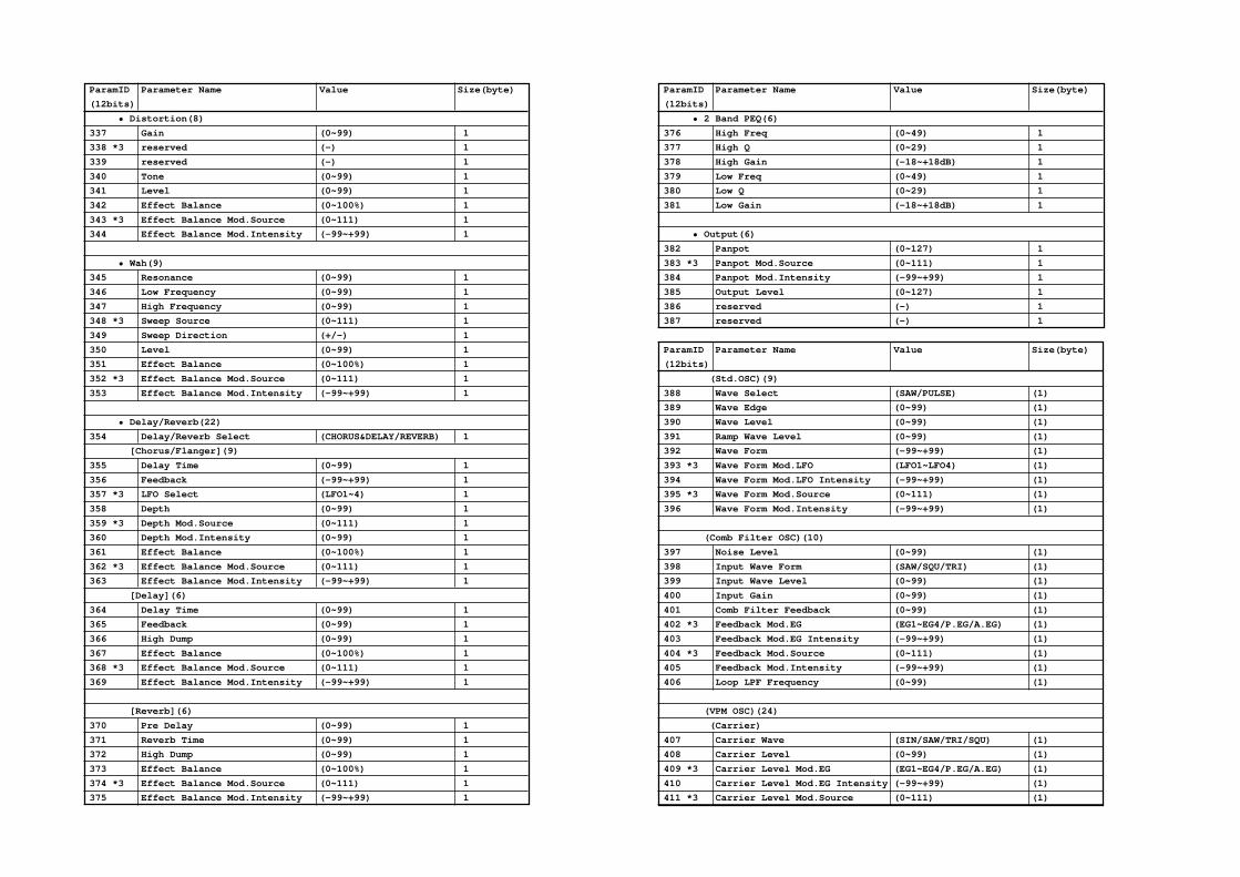
ParamID Parameter Name Value Size(byte)
(12bits)
• Distortion(8)
337 Gain (0~99) 1
338 *3 reserved (-) 1
339 reserved (-) 1
340 Tone (0~99) 1
341 Level (0~99) 1
342 Effect Balance (0~100%) 1
343 *3 Effect Balance Mod.Source (0~111) 1
344 Effect Balance Mod.Intensity (-99~+99) 1
• Wah(9)
345 Resonance (0~99) 1
346 Low Frequency (0~99) 1
347 High Frequency (0~99) 1
348 *3 Sweep Source (0~111) 1
349 Sweep Direction (+/-) 1
350 Level (0~99) 1
351 Effect Balance (0~100%) 1
352 *3 Effect Balance Mod.Source (0~111) 1
353 Effect Balance Mod.Intensity (-99~+99) 1
• Delay/Reverb(22)
354 Delay/Reverb Select (CHORUS&DELAY/REVERB) 1
[Chorus/Flanger](9)
355 Delay Time (0~99) 1
356 Feedback (-99~+99) 1
357 *3 LFO Select (LFO1~4) 1
358 Depth (0~99) 1
359 *3 Depth Mod.Source (0~111) 1
360 Depth Mod.Intensity (0~99) 1
361 Effect Balance (0~100%) 1
362 *3 Effect Balance Mod.Source (0~111) 1
363 Effect Balance Mod.Intensity (-99~+99) 1
[Delay](6)
364 Delay Time (0~99) 1
365 Feedback (0~99) 1
366 High Dump (0~99) 1
367 Effect Balance (0~100%) 1
368 *3 Effect Balance Mod.Source (0~111) 1
369 Effect Balance Mod.Intensity (-99~+99) 1
[Reverb](6)
370 Pre Delay (0~99) 1
371 Reverb Time (0~99) 1
372 High Dump (0~99) 1
373 Effect Balance (0~100%) 1
374 *3 Effect Balance Mod.Source (0~111) 1
375 Effect Balance Mod.Intensity (-99~+99) 1
ParamID Parameter Name Value Size(byte)
(12bits)
• 2 Band PEQ(6)
376 High Freq (0~49) 1
377 High Q (0~29) 1
378 High Gain (-18~+18dB) 1
379 Low Freq (0~49) 1
380 Low Q (0~29) 1
381 Low Gain (-18~+18dB) 1
• Output(6)
382 Panpot (0~127) 1
383 *3 Panpot Mod.Source (0~111) 1
384 Panpot Mod.Intensity (-99~+99) 1
385 Output Level (0~127) 1
386 reserved (-) 1
387 reserved (-) 1
ParamID Parameter Name Value Size(byte)
(12bits)
(Std.OSC)(9)
388 Wave Select (SAW/PULSE) (1)
389 Wave Edge (0~99) (1)
390 Wave Level (0~99) (1)
391 Ramp Wave Level (0~99) (1)
392 Wave Form (-99~+99) (1)
393 *3 Wave Form Mod.LFO (LFO1~LFO4) (1)
394 Wave Form Mod.LFO Intensity (-99~+99) (1)
395 *3 Wave Form Mod.Source (0~111) (1)
396 Wave Form Mod.Intensity (-99~+99) (1)
(Comb Filter OSC)(10)
397 Noise Level (0~99) (1)
398 Input Wave Form (SAW/SQU/TRI) (1)
399 Input Wave Level (0~99) (1)
400 Input Gain (0~99) (1)
401 Comb Filter Feedback (0~99) (1)
402 *3 Feedback Mod.EG (EG1~EG4/P.EG/A.EG) (1)
403 Feedback Mod.EG Intensity (-99~+99) (1)
404 *3 Feedback Mod.Source (0~111) (1)
405 Feedback Mod.Intensity (-99~+99) (1)
406 Loop LPF Frequency (0~99) (1)
(VPM OSC)(24)
(Carrier)
407 Carrier Wave (SIN/SAW/TRI/SQU) (1)
408 Carrier Level (0~99) (1)
409 *3 Carrier Level Mod.EG (EG1~EG4/P.EG/A.EG) (1)
410 Carrier Level Mod.EG Intensity (-99~+99) (1)
411 *3 Carrier Level Mod.Source (0~111) (1)

ParamID Parameter Name Value Size(byte)
(12bits)
412 Carrier Level Mod.Intensity (-99~+99) (1)
413 Table Shape (0~99) (1)
414 *3 Table Shape Mod.LFO (LFO1~LFO4) (1)
415 Table Shape Mod.LFO Intensity (-99~+99) (1)
416 *3 Table Shape Mod.Source (0~111) (1)
417 Table Shape Mod.Intensity (-99~+99) (1)
418 Feedback Gain (0~99) (1)
(Modulator)
419 Frequency Semi Tone (-12~+96) (1)
420 Frequency Fine Tune (-50~50) (1)
421 Modulator Pitch Keyboard Track (-99~+99) (1)
422 *3 Modulator Pitch Mod.Source (0~111) (1)
423 Modulator Pitch Mod.Intensity (-99~+99) (1)
424 Modulator Wave (SIN/SAW/TRI/SQU/OSC) (1)
425 Modulator Level (0~99) (1)
426 *3 Modulator Level Mod.EG (EG1~EG4/P.EG/A.EG) (1)
427 Modulator Level Mod.EG Int. (-99~+99) (1)
428 Modulator Level Mod.EG Int.KTrk (-99~+99) (1)
429 *3 Modulator Level Mod.Source (0~111) (1)
430 Modulator Level Mod.Intensity (-99~+99) (1)
(Mod.OSC)(11)
431 Modulation Type (RING/CROSS/SYNC) (1)
432 Input Select (OSC1/F.B./Noise) (1)
(Ring Modulation)
433 Ring Carrier Select (SIN/SAW/SQU) (1)
(Cross Modulation)
434 Cross Carrier Select (SIN/SAW/SQU) (1)
435 Cross Modulation Depth (0~99) (1)
436 *3 Cross Mod.Depth Mod.EG (EG1~EG4/P.EG/A.EG) (1)
437 Cross Mod.Depth Mod.EG Intensity (-99~+99) (1)
438 *3 Cross Mod.Depth Mod.Source (0~111) (1)
439 Cross Mod.Depth Mod.Intensity (-99~+99) (1)
(Sync Modulation)
440 Sync Slave Wave Select (SAW/TRI) (1)
441 Sync Modulator Shape (0~99) (1)
(Brass OSC)(34)
442 *6 Instrument Type (0~3) (1)
443 *3 Smooth Bending Controller (0~111) (1)
444 Smooth Bending Intensity (0~12) (1 Bit0~5)
445 Smooth Bending Direction (UP/DOWN/BOTH) (^ Bit6~7)
446 *3 Pressure EG (EG1~EG4/P.EG/A.EG) (1)
447 Pressure EG Intensity (-99~+99) (1)
448 *3 Pressure EG Int.Mod.Source (0~111) (1)
449 Pressure EG Int.Mod.Intensity (-99~+99) (1)
ParamID Parameter Name Value Size(byte)
(12bits)
450 *3 Pressure LFO (LFO1~LFO4) (1)
451 Pressure LFO Intensity (-99~+99) (1)
452 *3 Pressure Mod.Source (0~111) (1)
453 Pressure Mod.Intensity (-99~+99) (1)
454 reserved (-) (1)
455 reserved (-) (1)
456 Lip Charactor (0~99) (1)
457 *3 Lip Charactor Mod.Source (0~111) (1)
458 Lip Charactor Mod.Intensity (-99~+99) (1)
459 reserved (-) (1)
460 reserved (-) (1)
461 Bell Type (OPEN/MUTE) (1)
462 Bell Tone (0~99) (1)
463 Bell Resonance (0~99) (1)
464 Noise Level (0~99) (1)
465~476 reserved (-) (12)
(Reed OSC)(34)
477 *7 Instrument Type (0~12) (1)
478 *3 Smooth Bending Controller (0~111) (1)
479 Smooth Bending Intensity (0~12) (1 Bit0~5)
480 Smooth Bending Direction (UP/DOWN/BOTH) (^ Bit6~7)
481 *3 Pressure EG (EG1~EG4/P.EG/A.EG) (1)
482 Pressure EG Intensity (0~99) (1)
483 *3 Pressure EG Int.Mod.Source (0~111) (1)
484 Pressure EG Int.Mod.Intensity (-99~+99) (1)
485 *3 Pressure LFO (0~111) (1)
486 Pressure LFO Intensity (-99~+99) (1)
487 *3 Pressure Mod.Source (0~111) (1)
488 Pressure Mod.Intensity (-99~+99) (1)
489 reserved (-) (1)
490 reserved (-) (1)
491 *3 Reed Mod.Source (0~111) (1)
492 Reed Mod.Intensity (-99~+99) (1)
493 reserved (-) (1)
494 reserved (-) (1)
495 reserved (-) (1)
496 reserved (-) (1)
497 reserved (-) (1)
498 Noise Level (0~99) (1)
499~511 reserved (-) (13)
(Pluck OSC)(30)
512 Attack Level (0~99) (1)
513 Attack Level Velocity Control (-99~+99) (1)
514 Attack Noise Level (0~99) (1)
515 Attack Noise Level Vel.Control (-99~+99) (1)

ParamID Parameter Name Value Size(byte)
(12bits)
516 Attack Noise Filter Type (LPF/HPF/BPF) (1)
517 Attack Noise Filter Fc (0~99) (1)
518 Attack Noise Filter Fc Vel.Ctl. (-99~+99) (1)
519 Attack Noise Filter Resonance (0~99) (1)
520 Attack Curve Up (0~99) (1)
521 Attack Curve Up Velocity Ctl. (-99~+99) (1)
522 Attack Curve Down (0~99) (1)
523 Attack Curve Down Velocity Ctl. (-99~+99) (1)
524 Attack Edge (0~99) (1)
525 String Position (0~99) (1)
526 String Position Velocity Ctl. (-99~+99) (1)
527 *3 String Position Mod.Source (0~111) (1)
528 String Position Mod.Intensity (-99~+99) (1)
529 String Loss (0~99) (1)
530 String Loss Keyboard Track (-99~+99) (1)
531 *3 String Loss Mod.Source (0~111) (1)
532 String Loss Mod.Intensity (-99~+99) (1)
533 Inharmonicity Amount (0~99) (1)
534 Inharmonicity Keyboard Track (-99~+99) (1)
535 Decay (0~99) (1)
536 Decay Keyboard Track (-99~+99) (1)
537 Release (0~99) (1)
538 Release Keyboard Track (-99~+99) (1)
539 reserved (-) (1)
540 reserved (-) (1)
541 reserved (-) (1)
ParamID Parameter Name Value Size(byte)
(12bits)
• Controller Assignment(9)
542 *9 Wheel1 (0~100) 1
543 *9 Wheel2 (0~100) 1
544 *9 Wheel3(+) (0~100) 1
545 *9 Wheel3(-) (0~100) 1
546 *9 Ribbon(X) (0~100) 1
547 *9 Ribbon(Z) (0~100) 1
548 *9 Foot Pedal (0~100) 1
549 *10 Foot SW (0~11) 1
550 Ribbon(X) Valiable Center Point (OFF/ON) 1
ParamID Parameter Name Value Size(byte)
(12bits)
• Performance Editor(91)
[PE1](20)
(Knob1)
551 Parameter (0~255) 1
552 Left Value (0~100%) 1
553 Right Value (0~100%) 1
554 Curve (LINER/EXP/LOG) 1
555~ (Knob2) 4
559~ (Knob3) 4
563~ (Knob4) 4
567~ (Knob5) 4
571~ [PE2] 20
591~ [PE3] 20
611~ [PE4] 20
631 PE1 SW (OFF/ON) 1(Bit0)
632 PE2 SW (OFF/ON) ^(Bit1)
633 PE3 SW (OFF/ON) ^(Bit2)
634 PE4 SW (OFF/ON) ^(Bit3)
635 PE Nob1 Value (0~127) 1
636 PE Nob2 Value (0~127) 1
637 PE Nob3 Value (0~127) 1
638 PE Nob4 Value (0~127) 1
639 PE Nob5 Value (0~127) 1
640 Portamento SW (OFF/ON) 1
641 reserved (0) 1
642 reserved (0) 1
643 reserved (0) 1
644 reserved (0) 1
535

• Format of Program Parameter ID for Parameter Change Message (Sys Ex).
| S S S S I I I I I I I I I I I I
:==== ExID =====:================ Parameter ID =================:
ExID
(4bits)
0 (Identified by Parameter ID only.)
1 OSC 1
2 OSC 2
• Notes:
[*1] OSC Set
#Set OSC 1 OSC 2
Set 1 Std.OSC Std.OSC
Set 2 Std.OSC Comb Filter OSC
Set 3 Std.OSC VPM OSC
Set 4 Std.OSC Modulation OSC
Set 5 Comb Filter OSC Comb Filter OSC
Set 6 Comb Filter OSC VPM OSC
Set 7 Comb Filter OSC Modulation OSC
Set 8 VPM OSC VPM OSC
Set 9 VPM OSC Modulation OSC
Set 10 Brass no oscillator
Set 11 Reed no oscillator
Set 12 Pluck no oscillator
[*2] Determined by "OSC Set" parameter.
[*3] Modulation Source
ID Modulation Source
0 Off
1 EG1
2 EG2
3 EG3
4 EG4
5 Pitch EG
6 Amp EG
7 LFO1
8 LFO2
9 LFO3
10 LFO4
11 Portamento
12 Note No.
13 Velocity
14 Pitch Bender
15 After Touch
16 Control Change #0
: :
111 Control Change #95
[*4] LFO Wave Form
ID Wave Form
0 SIN '0
1 SIN '180
2 COS '0
3 COS '180
4 TRI '0
5 TRI '90
6 TRI '180
7 TRI '270
8 SAW UP '0
9 SAW UP '180
10 SAW DOWN '0
11 SAW DOWN '180
12 SQR '0
13 SQR '180
14 RAMDOM 1
15 RAMDOM 2
16 RAMDOM 3
17 RAMDOM 4
18 RAMDOM 5
19 RAMDOM 6
20 Growl
21 Guitar Vibrato
22 Step TRI
23 Step SAW
24 Step TRI4
25 Step SAW6
26 Exp SAW UP
27 Exp SAW DOWN
28 Exp TRI
29 String Vibrato
[*5] Pitch Bender Step
0 :Continuous
1 :1/8[Semitone]
2 :1/4
3 :1/2
4 :1
:
15:12
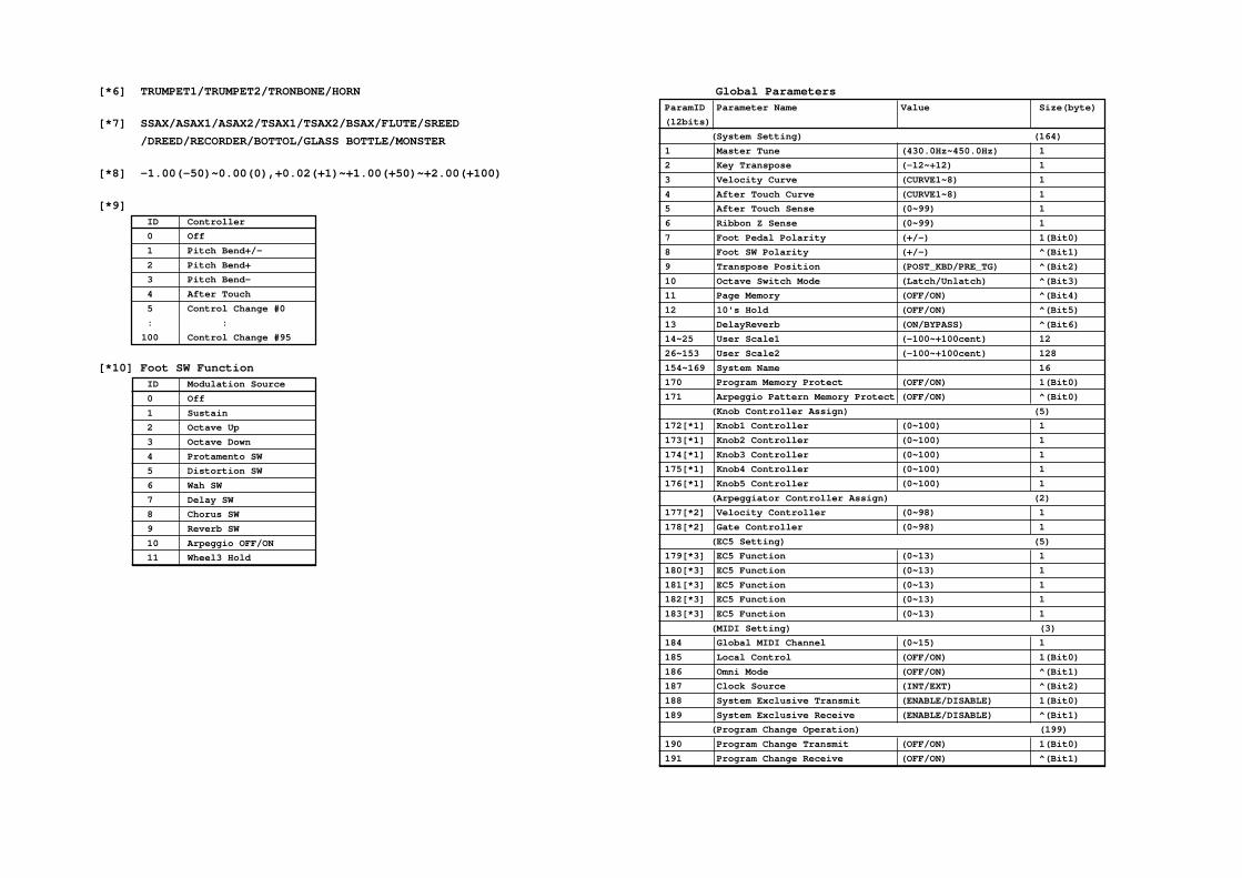
[*6] TRUMPET1/TRUMPET2/TRONBONE/HORN
[*7] SSAX/ASAX1/ASAX2/TSAX1/TSAX2/BSAX/FLUTE/SREED
/DREED/RECORDER/BOTTOL/GLASS BOTTLE/MONSTER
[*8] -1.00(-50)~0.00(0),+0.02(+1)~+1.00(+50)~+2.00(+100)
[*9]
ID Controller
0 Off
1 Pitch Bend+/-
2 Pitch Bend+
3 Pitch Bend-
4 After Touch
5 Control Change #0
: :
100 Control Change #95
[*10] Foot SW Function
ID Modulation Source
0 Off
1 Sustain
2 Octave Up
3 Octave Down
4 Protamento SW
5 Distortion SW
6 Wah SW
7 Delay SW
8 Chorus SW
9 Reverb SW
10 Arpeggio OFF/ON
11 Wheel3 Hold
Global Parameters
ParamID Parameter Name Value Size(byte)
(12bits)
(System Setting) (164)
1 Master Tune (430.0Hz~450.0Hz) 1
2 Key Transpose (-12~+12) 1
3 Velocity Curve (CURVE1~8) 1
4 After Touch Curve (CURVE1~8) 1
5 After Touch Sense (0~99) 1
6 Ribbon Z Sense (0~99) 1
7 Foot Pedal Polarity (+/-) 1(Bit0)
8 Foot SW Polarity (+/-) ^(Bit1)
9 Transpose Position (POST_KBD/PRE_TG) ^(Bit2)
10 Octave Switch Mode (Latch/Unlatch) ^(Bit3)
11 Page Memory (OFF/ON) ^(Bit4)
12 10's Hold (OFF/ON) ^(Bit5)
13 DelayReverb (ON/BYPASS) ^(Bit6)
14~25 User Scale1 (-100~+100cent) 12
26~153 User Scale2 (-100~+100cent) 128
154~169 System Name 16
170 Program Memory Protect (OFF/ON) 1(Bit0)
171 Arpeggio Pattern Memory Protect (OFF/ON) ^(Bit0)
(Knob Controller Assign) (5)
172[*1] Knob1 Controller (0~100) 1
173[*1] Knob2 Controller (0~100) 1
174[*1] Knob3 Controller (0~100) 1
175[*1] Knob4 Controller (0~100) 1
176[*1] Knob5 Controller (0~100) 1
(Arpeggiator Controller Assign) (2)
177[*2] Velocity Controller (0~98) 1
178[*2] Gate Controller (0~98) 1
(EC5 Setting) (5)
179[*3] EC5 Function (0~13) 1
180[*3] EC5 Function (0~13) 1
181[*3] EC5 Function (0~13) 1
182[*3] EC5 Function (0~13) 1
183[*3] EC5 Function (0~13) 1
(MIDI Setting) (3)
184 Global MIDI Channel (0~15) 1
185 Local Control (OFF/ON) 1(Bit0)
186 Omni Mode (OFF/ON) ^(Bit1)
187 Clock Source (INT/EXT) ^(Bit2)
188 System Exclusive Transmit (ENABLE/DISABLE) 1(Bit0)
189 System Exclusive Receive (ENABLE/DISABLE) ^(Bit1)
(Program Change Operation) (199)
190 Program Change Transmit (OFF/ON) 1(Bit0)
191 Program Change Receive (OFF/ON) ^(Bit1)

[*1] Knob Controller Assign
ID Controller
0 Off
1 Pitch Bend+/-
2 Pitch Bend+
3 Pitch Bend-
4 After Touch
5 Control Change #0
: :
100 Control Change #95
[*2] Arpeggiator Controller Assign
ID Controller
0 Off
1 Pitch Bend
2 After Touch
3 Control Change #0
: :
98 Control Change #95
[*3] EC5 Function
ID Modulation Source
0 Off
1 Sustain
2 Program Up
3 Program Down
4 Octave Up
5 Octave Down
6 Protamento SW
7 Distortion SW
8 Wah SW
9 Delay SW
10 Chorus SW
11 Reverb SW
12 Arpeggio OFF/ON
13 Wheel3 Hold
ParamID Parameter Name Value Size(byte)
(12bits)
(Program Bank Select Map)
192 Bank A MSB (OFF/0~127) 1
193 Bank A LSB (OFF/0~127) 1
194 Bank B MSB (OFF/0~127) 1
195 Bank B LSB (OFF/0~127) 1
196 Bank C MSB (OFF/0~127) 1
197 Bank C LSB (OFF/0~127) 1
(Program Select Map)
198 A00 (0~127) 1
: :
261 A63 (0~127) 1
262 B00 (0~127) 1
: :
325 B63 (0~127) 1
326 C00 (0~127) 1
: :
389 C63 (0~127) 1
(Pitch Bend Operation) (2)
390 Pitch Bend Transmit (OFF/ON) 1(Bit0)
391 Pitch Bend Recieve (DIS/ENA/INTP) ^(Bit1~2)
392 Pitch Bend Return (OFF/ON) ^(Bit3)
393 Pitch Bend Translation (PBEND/ATOUCH/CC#0~95) 1
(After Touch Operation) (2)
394 After Touch Transmit (OFF/ON) 1(Bit0)
395 After Touch Recieve (DIS/ENA/INTP) ^(Bit1~2)
396 After Touch Return (OFF/ON) ^(Bit3)
397 After Touch Translation (PBEND/ATOUCH/CC#0~95) 1
(Control Change #0 Operation) (192)
398 Control Change #0 Transmit (OFF/ON) 1(Bit0)
399 Control Change #0 Recieve (DIS/ENA/INTP) ^(Bit1~2)
400 Control Change #0 Return (OFF/ON) ^(Bit3)
401 Control Change #0 Translation (PBEND/ATOUCH/CC#0~95) 1
402~ (Control Change #1 Operation) 2
406~ (Control Change #2 Operation) 2
:
778~781 (Control Change #95 Operation) 2
574

Arpeggio Pattern Parameters ParamID Parameter Name Value Size(byte)
(12bits)
(Base Parameter) (32)
1~16 reserved 16
17 reserved 1
18 Step Base (4,4T,8,8T,16,16T) 1
19 Sort (OFF/ON) 1
20 Keyboard Scan Zone Bottom (C-1~G9) 1
21 Keyboard Scan Zone Top (C-1~G9) 1
22 Velocity (1~127,KEY,STEP) 1
23 reserved 1
24 Velocity Controller Intensity (-99~+99) 1
25 Gate (1%~100%,STEP) 1
26 reserved 1
27 Gate Controller Intensity (-99~+99) 1
28 [*1] Arpeggio Type (0~3) 1
29 Octave Alternation (UP/DOWN/UP&DOWN) 1
30~32 reserved 3
(Step1)
33 Offset (-49%~+49%) 1
34 Tone (1~12,LOOP) 1
35 Velocity (1~127) 1
36 Gate (OFF,1%~100%) 1
37~ (Step2) 4
: : :
125~128 (Step24) 4
128
[*1] Arpeggio Type
0:As Played
1:As Played(Fill)
2:Running Up
3:Up & Down

175
6.A
pp
end
ix
6.7 TroubleshootingProblem Action
Nothing appears in the LCD when the POWER • Is the power cable connected to an AC outlet? �P/B G, P.4switch is pressed. • Is the amp turned on and connected correctly?
No sound! • Are the amp, and/or headphones connected correctly? �P/B G, P.4• Is the Master Volume of the Prophecy raised? �P/B G, P.6• Is the Global section Local setting turned ON? �P/B G, P.5• Are the level-related parameters in each section set to 0?
Sound does not stop! • Is the Hold setting turned OFF? �P G, P.127• Is the Damper Polarity setting correct? �P G, P.136
Sound is different than the settings! • Have you executed the Write operation after editing? �P/B G, P.31
Cannot save data to card! • Is the Protect switch of the card turned ON? �P G, P.152• Are you using a ROM card? �P G, P.152• Is the card inserted correctly? �P G, P.152• Is the Global section Memory Protect setting OFF? �P G, P.148
Cannot load data from card! • Does the card contain data? �P G, P.152• Is the card inserted correctly? �P G, P.152
Delay or reverb settings do not work! • Is the Global section Delay/Reverb setting ON? �P G, P.135
Cannot write programs! • Is the Global section Memory Protect setting OFF? �P G, P.148
Transpose or Velocity Curve is not transmitted/ • Are the Global section Transposition settings correct?received correctly! �P G, P.133
Arpeggio does not start! • Is the Global section Clock Source setting correct? �P G, P.139• Is the Keyboard scan setting of Pattern Define correct? �P G, P.7
Cannot control through MIDI! • Is the MIDI cable connected correctly? �P/B G, P.5• Does the MIDI channel on which the external device is transmitting
match the Global Channel of the Prophecy? �P G, P.139
6.8 Error messagesError message Action
Program write error
WRITE ERROR <Program Memory is protected> Turn off Program Memory Protect.
WRITE ERROR <Please insert CARD?> Insert a card.
WRITE ERROR <Card is write protected> Trun off the card’s Write Protect switch.
Program Change error
PROGRAM READ ERROR <Please insert CARD> Insert a card.
Pattern Bank/Pattern Change error
PATTERN READ ERROR <Please insert CARD> Insert a card.
ACCESS ERROR <CARD is wrong format> Insert the correct card.
Program Bank Select error
ACCESS ERROR <Please insert CARD> Insert a card.
ACCESS ERROR <CARD is wrong format> Insert the correct card.
Battery Check error
INTERNAL BATTERY IS LOW <Press any key> The internal backup battery has run down. Contact your nearby dealer or a Korg service station.
CARD BATTERY IS LOW <Press any key> The backup battery of the card has run down. Replace the battery.

176
6.9 Other messages• Pattern define messages
* WARNING <PatternMemory is protected> The ARPEGGIO PATTERN DEFINE key was pressed when Pattern MemoryProtect is ON. If you wish to change the parameter values, turn Pattern MemoryProtect OFF (GLB-20,4).
* CARD PAT CAN’T BE CHANGED <Copy to Int> The ARPEGGIO PATTERN DEFINE key was pressed when a CARD PAT isselected. CARD PAT pattern parameters cannot be changed directly. Copy themto an INT PAT and modify them there.
MIDI receive messages
MIDI WRITE REQUEST RECEIVED <Completed>
EDIT PROGRAM DUMP RECEIVED <Completed>
PROGRAM DATA DUMP RECEIVED <Completed>
PATTERN DATA DUMP RECEIVED <Completed>
GLOBAL DATA DUMP RECEIVED <Completed>
ALL DATA DUMP RECEIVED <Completed>
Message Situation and result
<Press ENTER> A setting needs to be finalized. Waiting for the ENTER key.
<Are you sure?> Waiting for confirmation by the ENTER key.
<Completed> Processing of a Utility function etc. has been completed.
<Ignore> In most cases, a copy or swap operation that changes nothing. Operation isabandoned.
<OSC Type Error> In Oscillator Copy, the oscillator types are different. Operation is abandoned.
<Fx Type Error> In Effect Copy, the effect types are different. Operation is abandoned.
<Center OK?> When calibrating wheel 1 or 3, waiting for center settings.
<Value Mismatch> When calibrating a controller, the setting is inappropriate. Operation is cancelled.
<Mem Protected> During Factory Data Load or Arpeggio Pattern Copy etc., protect is on for Programor Pattern memory. Operation is cancelled.
<No Card> In most cases, when card access is attempted when no card is inserted.Operation is cancelled.
<Illegal Format> In most cases, when there is a problem with the card format during card access.Operation is cancelled.
<Format&Write?> When writing or saving to a card, the card format is not correct. If the ENTER keyis pressed, the card will be formatted and the Write or Save operation will beexecuted.
<Write Protect> When saving is attempted for a card whose Protect switch is ON. Operation iscancelled.
<Card Trouble> When a problem has occurred during card access. Operation is cancelled.
<Now Playing> The demo songs are playing.

SOLO
SYN
THESIZ
ER Param
eter Guide
2E
KORG INC.
KORG INC.15 - 12, Shimotakaido 1 - chome, Suginami-ku, Tokyo, Japan.
0710 CTH Printed in Japan
NOTICEKORG products are manufactured under strict specifications and voltages required by each
country. These products are warranted by the KORG distributor only in each country. Any
KORG product not sold with a warranty card or carrying a serial number disqualifies the product
sold from the manufacturer’s/distributor’s warranty and liability. This requirement is for your
own protection and safety.