Embed Size (px)
Citation preview
MOBILELEKTRONIKGMBH
Bössingerstraße 33 D-74243 Langenbeutingen � +49 (0) 79 46 – 91 94 0 FAX +49 (0) 79 46 – 91 94 130 http://www.mobil-elektronik.com
System Documentation - Part 1 General System Description Installation Guideline Maintenance Instructions
Electro-Hydraulic Auxiliary Steering System
for Rear Axles
Type: SLC 019 146
Prope
rty o
f Am
erica
n Airli
nes
System Description Page 2 of 23
Installation Guideline Version 01.00 MOBILELEKTRONIKGMBH Maintenance Instructions
Manual_SLC019146_Part1_V0100.doc 0 Table of Figures
Table of Contents
Table of Figures..................................................................................................................... 4
History .................................................................................................................................... 5
1 General ................................................................................................................................ 6
1.1 Signs and Symbols .................................................................................................................................... 6 1.2 List of Abbreviations.................................................................................................................................. 6 1.3 Definitions Concerning the Safety Angle Transducers.......................................................................... 7 1.4 Safety Instructions ..................................................................................................................................... 8 1.5 Functional Principle of the Closed Steering System Control Loop...................................................... 9 1.6 General System Description EHLA Plus .............................................................................................. 10
1.6.1 System Structure EHLA Plus.............................................................................................................................................. 10 1.6.2 Safety Concept EHLA Plus ................................................................................................................................................. 11
1.7 Utilities for Diagnostics and Service...................................................................................................... 12
2 Installation Guideline ....................................................................................................... 13
2.1 Safety Instructions ................................................................................................................................... 13 2.2 Safety Steering Computer ....................................................................................................................... 14 2.3 Safety Angle Transducer ......................................................................................................................... 14
2.3.1 Assembly with Linkage Arm and Coupling Bar .................................................................................................................. 14 2.3.1.1 General Guideline.......................................................................................................................................................... 14 2.3.1.2 Selecting the Assembly Area ......................................................................................................................................... 15 2.3.1.3 Type of Coupling Bar ..................................................................................................................................................... 15 2.3.1.4 Kinematic Considerations for Angle Transducer Mounting ............................................................................................. 15
2.3.2 Assembly onto the Steering Knuckle Bearing .................................................................................................................... 16 2.3.3 Assembly inside the Steering Knuckle Bearing.................................................................................................................. 16
2.4 Overall System Wiring ............................................................................................................................. 17 2.4.1 Basic Specifications ............................................................................................................................................................. 17 2.4.2 Further Specifications .......................................................................................................................................................... 18
2.5 Proportional Hydraulic Unit..................................................................................................................... 19 2.6 Steering Cylinder...................................................................................................................................... 19 2.7 Pump, Filter and Tank.............................................................................................................................. 20 2.8 Oil ............................................................................................................................................................... 20
3 Maintenance Instructions ................................................................................................ 21
3.1 Safety Instructions ................................................................................................................................... 21 3.1.1 Safety Steering Computer .................................................................................................................................................... 21 3.1.2 Steering Systems with Hydraulic Accumulators ................................................................................................................ 21 3.1.3 Working within the Wheel Slewing Range........................................................................................................................... 21
3.2 Maintenance Overview............................................................................................................................. 22 3.3 Safety Steering Computer ....................................................................................................................... 22 3.4 Safety Angle Transducer ......................................................................................................................... 22
Prope
rty o
f Am
erica
n Airli
nes

System Description Page 3 of 23
Installation Guideline Version 01.00 MOBILELEKTRONIKGMBH Maintenance Instructions
Manual_SLC019146_Part1_V0100.doc 0 Table of Figures
3.5 Proportional Hydraulic Unit and Accumulator ...................................................................................... 23 3.6 Steering Cylinder and Mechanical Connection..................................................................................... 23 3.7 Pump, Filter and Tank.............................................................................................................................. 23
Prope
rty o
f Am
erica
n Airli
nes
System Description Page 4 of 23
Installation Guideline Version 01.00 MOBILELEKTRONIKGMBH Maintenance Instructions
Manual_SLC019146_Part1_V0100.doc 0 Table of Figures
Table of Figures Figure 1 - Function Principle of the Steering Control........................................................................................9 Figure 2 - System Structure EHLA Plus ..........................................................................................................10
Prope
rty o
f Am
erica
n Airli
nes

System Description Page 5 of 23
Installation Guideline Version 01.00 MOBILELEKTRONIKGMBH Maintenance Instructions
Manual_SLC019146_Part1_V0100.doc 0 History
History File Manual_SLC019146_Part1_V0100.doc
01.00 2011-05-09 TH new document based on “Manual_EHLA-Multi_Std_Part 1_V0203.doc”
Version
Subject to technical modification
Prope
rty o
f Am
erica
n Airli
nes

System Description Page 6 of 23
Installation Guideline Version 01.00 MOBILELEKTRONIKGMBH Maintenance Instructions
Manual_SLC019146_Part1_V0100.doc 1 General
1 General The system documentation EHLA (German: “Elektro-Hydraulische Lenk-Anlage”; electro-hydraulic steering system) comprises four parts:
1. System description, installation and maintenance 2. Project specific documentation
3. Commissioning and diagnostics 4. List of alarm codes
This first part on hand describes the structure of the steering system in general, the principles for installing the systems in utility vehicles and the common maintenance instructions valid for all systems. The following declared symbols and abbreviations apply to all four parts of the system documentation.
1.1 Signs and Symbols
This symbol indicates text positions, which have to be observed absolutely. Non-observance can cause damages and even injuries of persons!
This symbol indicates text positions containing directions for installation, commissioning, maintenance and operation of the system.
1.2 List of Abbreviations AI Analogue Input
CAN Controller Area Network DO Digital Output
DI Digital Input EEA Electronic Input/Output Terminal EIZ Electronic Installations Accessory
EHLA Electronic-Hydraulic Steering System LED Light Emitting Diode ME Mobil Elektronik GmbH
PHY Proportional Hydraulic Unit PWM Pulse Width Modulated
SLC Safety Steering Computer +UB Supply voltage (battery voltage) 0V-GND Power ground
Prope
rty o
f Am
erica
n Airli
nes
System Description Page 7 of 23
Installation Guideline Version 01.00 MOBILELEKTRONIKGMBH Maintenance Instructions
Manual_SLC019146_Part1_V0100.doc 1 General
1.3 Definitions Concerning the Safety Angle Transducers Angle Transducer Front Axle [n] [n = 1,2])
Depending on the applied hardware, steering systems with up to 2 set point generators are implementable (e.g. steered front axle of the vehicle and an additional set point generator like joystick, rotary encoder). In order to keep the documentation uniform the following definition of terms is appointed:
documentation: angle transducer front axle [n]
hardware display: „P[n]“ or „Poti [n]“ Note: Set point generators like joysticks or rotary encoders are in terms of the system function considered as front axles. Respectively the documentation is using the unique term “front axle”.
Angle Transducer Rear Axle [n] [n = 1...4]
Depending on the applied hardware, steering systems with up to 4 electro-hydraulically steered axles are available. In order to keep the documentation uniform the following definition of terms is appointed:
documentation: angle transducer rear axle [n]
hardware display: „A[n]“ or „Axle [n]“
Prope
rty o
f Am
erica
n Airli
nes
System Description Page 8 of 23
Installation Guideline Version 01.00 MOBILELEKTRONIKGMBH Maintenance Instructions
Manual_SLC019146_Part1_V0100.doc 1 General
1.4 Safety Instructions The EHLA safety steering system has been developed as an electro-hydraulic control system for rear axle auxiliary steering. This means that primarily the conventionally steered front axle determines the direction of travel and the rear axle(s) provide auxiliary steering. The system design is in accordance with the requirements of ECE-R 79, Appendix 6. The safety steering computer has TÜV type-testing approval and meets the requirements of Category 3 of EN 954-1.The steering system only meets the complex safety requirements when all installed and employed system components are in accordance to specifications and regulations set out by MOBIL ELEKTRONIK. Unauthorized tampering with the steering system or its components will invalidate any warranties issued by MOBIL ELEKTRONIK.
Directed use of the steering system: • No modifications of the steering system allowed. • Only installing the steering system in vehicle types approved by MOBIL ELEKTRONIK allowed. Modifying the system and its components or installing the steering system in other vehicle models without permission of MOBIL–ELEKTRONIK will invalidate the CE sign and all guarantees. In this case, the factory given warranties are invalid.
Handling of the steering system: • Specialist personnel only allowed installing, commissioning and servicing the steering system.
• Provide adequate protection for the electronic components during work on the vehicle (painting, welding, etc.). Remove the safety steering computer from the vehicle during welding operations in particular.
Improper handling of the steering system and its components will invalidate any warranties issued by MOBIL ELEKTRONIK.
In no case, MOBIL ELEKTRONIK will be reliable for direct and indirect damages resulting from any system failures of the steering system or from wrong descriptions in this document. Pro
perty
of A
mer
ican
Airline
s
System Description Page 9 of 23
Installation Guideline Version 01.00 MOBILELEKTRONIKGMBH Maintenance Instructions
Manual_SLC019146_Part1_V0100.doc 1 General
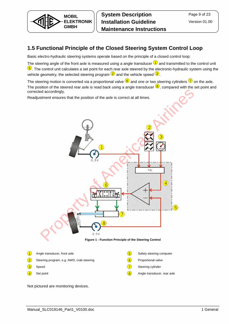
1.5 Functional Principle of the Closed Steering System Control Loop Basic electro-hydraulic steering systems operate based on the principle of a closed control loop:
The steering angle of the front axle is measured using a angle transducer
1 and transmitted to the control unit
5 . The control unit calculates a set point for each rear axle steered by the electronic-hydraulic system using the vehicle geometry, the selected steering program
2 and the vehicle speed
3 .
The steering motion is converted via a proportional valve
6 and one or two steering cylinders
7 on the axle. The position of the steered rear axle is read back using a angle transducer
8 , compared with the set point and corrected accordingly. Readjustment ensures that the position of the axle is correct at all times.
Figure 1 - Function Principle of the Steering Control
1 Angle transducer, front axle 5 Safety steering computer
2 Steering program, e.g. AWD, crab steering 6 Proportional valve
3 Speed 7 Steering cylinder
4 Set point 8 Angle transducer, rear axle
Not pictured are monitoring devices.
Prope
rty o
f Am
erica
n Airli
nes
System Description Page 10 of 23
Installation Guideline Version 01.00 MOBILELEKTRONIKGMBH Maintenance Instructions
Manual_SLC019146_Part1_V0100.doc 1 General
1.6 General System Description EHLA Plus is an electro-hydraulic auxiliary steering system for driven axles, e.g. in heavy vehicles with multiple
axles, in agricultural applications and in special vehicles travelling at low speeds.
is multiple installed in vehicles with driven rear axle which require high flexible steering systems. The electronic control of the axle supports all possible standard steering programs such as AWD, diagonal (crab steering) and independent manual steering. However, the system also supports special application-specific functions such as offset steering (ground protection), slope compensation and plough steering on agricultural vehicles.
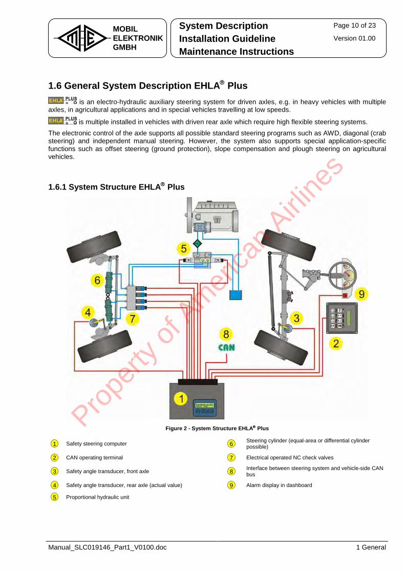
1.6.1 System Structure EHLA Plus
Figure 2 - System Structure EHLA Plus
1 Safety steering computer 6 Steering cylinder (equal-area or differential cylinder possible)
2 CAN operating terminal 7 Electrical operated NC check valves
3 Safety angle transducer, front axle 8 Interface between steering system and vehicle-side CAN bus
4 Safety angle transducer, rear axle (actual value) 9 Alarm display in dashboard
5 Proportional hydraulic unit
Prope
rty o
f Am
erica
n Airli
nes
System Description Page 11 of 23
Installation Guideline Version 01.00 MOBILELEKTRONIKGMBH Maintenance Instructions
Manual_SLC019146_Part1_V0100.doc 1 General
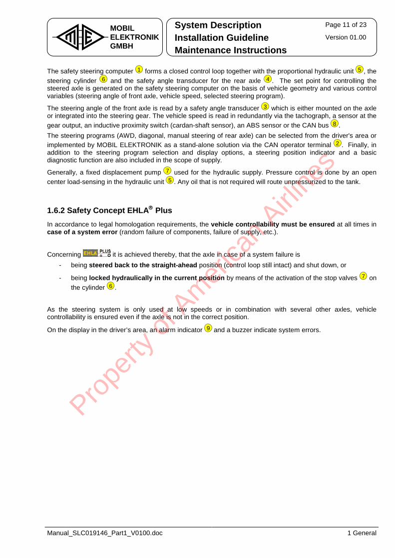
The safety steering computer
1 forms a closed control loop together with the proportional hydraulic unit
5 , the steering cylinder
6 and the safety angle transducer for the rear axle
4 . The set point for controlling the steered axle is generated on the safety steering computer on the basis of vehicle geometry and various control variables (steering angle of front axle, vehicle speed, selected steering program).
The steering angle of the front axle is read by a safety angle transducer
3 which is either mounted on the axle or integrated into the steering gear. The vehicle speed is read in redundantly via the tachograph, a sensor at the gear output, an inductive proximity switch (cardan-shaft sensor), an ABS sensor or the CAN bus
8 .The steering programs (AWD, diagonal, manual steering of rear axle) can be selected from the driver's area or implemented by MOBIL ELEKTRONIK as a stand-alone solution via the CAN operator terminal
2 . Finally, in addition to the steering program selection and display options, a steering position indicator and a basic diagnostic function are also included in the scope of supply.
Generally, a fixed displacement pump
7 used for the hydraulic supply. Pressure control is done by an open center load-sensing in the hydraulic unit
5 . Any oil that is not required will route unpressurized to the tank.
1.6.2 Safety Concept EHLA Plus In accordance to legal homologation requirements, the vehicle controllability must be ensured at all times in case of a system error (random failure of components, failure of supply, etc.).
Concerning it is achieved thereby, that the axle in case of a system failure is - being steered back to the straight-ahead position (control loop still intact) and shut down, or
- being locked hydraulically in the current position by means of the activation of the stop valves
7 on the cylinder
6 .
As the steering system is only used at low speeds or in combination with several other axles, vehicle controllability is ensured even if the axle is not in the correct position.
On the display in the driver’s area, an alarm indicator
9 and a buzzer indicate system errors.
Prope
rty o
f Am
erica
n Airli
nes
System Description Page 12 of 23
Installation Guideline Version 01.00 MOBILELEKTRONIKGMBH Maintenance Instructions
Manual_SLC019146_Part1_V0100.doc 1 General
1.7 Utilities for Diagnostics and Service For diagnostics, service and start-up there are several tools available:
1. Onboard operation device (display and keys on the electronic, optional equipment)
2. PC-Service-Software „WinPCS“ for start-up, parameter setting and diagnostics (RS232-interface and PC/notebook)
3. CAN diagnostics terminal „EEA 092 801“ for start-up, parameter setting and diagnostics (CAN interface, stand-alone hand-held device).
4. Onboard diagnostics according SAE J1939 (option) (CAN interface for use with dashboard display or PC/notebook).
5. Flash-Software „WinEEA“ for software update (RS232-interface and PC/notebook)
Prope
rty o
f Am
erica
n Airli
nes
System Description Page 13 of 23
Installation Guideline Version 01.00 MOBILELEKTRONIKGMBH Maintenance Instructions
Manual_SLC019146_Part1_V0100.doc 2 Installation Guideline
2 Installation Guideline
2.1 Safety Instructions
Regarding safety functions, steering systems have top priority.
An electro-hydraulic steering system for rear axle auxiliary steering is safety related equatable with conventional steering systems.
A proper operation of each individual component is essential to the safety and reliability of the entire electro-hydraulic steering system and therefore to the maneuverability of the vehicle. The safe and reliable mechanical and electrical installation of the individual components is essential to the operation of the overall system in accordance with specification.
Although each individual component is suitable for use in mobile applications and is designed to provide the requisite durability, the use of sensitive precision parts internally requires absolute cleanliness and appropriate care during installation.
Prope
rty o
f Am
erica
n Airli
nes
System Description Page 14 of 23
Installation Guideline Version 01.00 MOBILELEKTRONIKGMBH Maintenance Instructions
Manual_SLC019146_Part1_V0100.doc 2 Installation Guideline
2.2 Safety Steering Computer The assembly site of the safety steering computer is inside the vehicle interior or in the control cabinet and should be selected in the manner to ensure the avoidance of direct contact with dust, moisture and direct sunlight. If the computer features a display, it should to be visible after assembly. When using safety steering computers with 7-segment displays, it is possible to rotate the display information by 180° via software parameter, if demanded by assembly conditions.
2.3 Safety Angle Transducer The linkage of the angle transducer is of particular importance. It is a steering component and is as important as a tie rod e.g. on the front axle. The following safety instructions are to be strictly adhered to.
The linkage design of the angle transducer must accord with the guidelines for steering components. Reckon uncontrollable breaking away of the steered axle when the linkage breaks, as it would be in the case of a broken tie rod.
Drilling and welding on steering components only allowed after authorization by the vehicle manufacturer!
2.3.1 Assembly with Linkage Arm and Coupling Bar
2.3.1.1 General Guideline For mounting the angle transducer linkage to the tie rod, the steering arm or the axle beam end, please pay attention the following points: • Use existing mounting points if possible. • There are at least four M8 screws needed if clamps used as linkage to the steering arm or tie rod. • Use corrosion-resistant screws with property class 8.8 to mount the angle transducer. • Use suitable screw locking (self-locking nut, lock washer, liquid screw retention). • If levels of vibration are expected to be high (e.g. mounting to axle housing), the safety angle
transducer should be installed with its shaft in a horizontal position (mount arm pointing downwards or upwards!).
Prope
rty o
f Am
erica
n Airli
nes
System Description Page 15 of 23
Installation Guideline Version 01.00 MOBILELEKTRONIKGMBH Maintenance Instructions
Manual_SLC019146_Part1_V0100.doc 2 Installation Guideline
2.3.1.2 Selecting the Assembly Area Select the assembly area of the safety angle transducer regarding the following aspects: • Avoid skid area of snow chains and the region of stone chipping.• Do not reduce the ground clearance of the vehicle by the safety angle transducer and its linkage. • No external forces should expose to the safety angle transducer and its linkage, if the vehicle caves in
on off-roads. • If necessary, protect assembly area with plates and safety bars.• Ensure enough freedom of motion (i.e. 10 mm, in harsh applications at least 20 mm) to neighboring
vehicle components under all operating conditions (e.g. compression and expansion of the chassis suspension, reaching the full steer angle, operation with snow chains, etc.).
• The safety angle transducer linkage is easy checkable (i.e. accessible) by maintenance personnel. • If a single cylinder is used per axle: The angle transduce is meant to measure the angle of the axle
without mechanical loose and without elastic movement. Therefor the angle transducer shouldt be mounted at the same side of the axle where the cylinder is mounted.
2.3.1.3 Type of Coupling Bar The coupling bars must meet the following requirements: • Use coupling bars with a hinge to equalize all production and assembly tolerances and to prevent
bracing the safety angle transducer. • Use form-locking hinge heads (nominal size 8 mm). • Use tough, solid steel with reliable protection against corrosion for the coupling bar (an ideal choice would
be stainless steel, minimum diameter 8 mm with M8 right-handed or left-handed thread at both ends). • The maximum length of the coupling bar must not exceed 400 mm.
2.3.1.4 Kinematic Considerations for Angle Transducer Mounting The safety angle transducer should be connected/mounted so, that • compared to the straight-ahead position the maximum deflection of the angle transducer arm is
between 25° - 55° (on each side at full steer angle of the steering). • a preferably proportional ratio between the wheel turning angle and the sensor deflection angle exists. • the safety angle transducer is centered when the axle is in the straight-ahead position, in order to enable
electronic axle alignment (maximum permissible tolerance ± 5°),.
Prope
rty o
f Am
erica
n Airli
nes
System Description Page 16 of 23
Installation Guideline Version 01.00 MOBILELEKTRONIKGMBH Maintenance Instructions
Manual_SLC019146_Part1_V0100.doc 2 Installation Guideline
2.3.2 Assembly onto the Steering Knuckle Bearing Assembling the angle transducer onto the cap of the steering knuckle bearing is only possible after consulting the axle manufacturer and after individual verification and preparation of the axle. Anti-twist protection for the angle transducer provides an elastic plate made from spring steel plate.
2.3.3 Assembly inside the Steering Knuckle Bearing Integrating an angle transducer inside the steering knuckle bearing demands a modification both the steering knuckle bearing and the angle transducer and is only possible after consulting the axle manufacturer and MOBIL-ELEKTRONIK after individual verification and preparation of the axle and the sensor. Assembling has to follow the respective advice.
Prope
rty o
f Am
erica
n Airli
nes
System Description Page 17 of 23
Installation Guideline Version 01.00 MOBILELEKTRONIKGMBH Maintenance Instructions
Manual_SLC019146_Part1_V0100.doc 2 Installation Guideline
2.4 Overall System Wiring Inadequate electric installation is a main cause for malfunction of the complete system. Alarm messages are frequently basing on illegal large spreading of the redundant signals of angle transducers or on disturbed CAN connections. Therefore miscellaneous documents were issued, which should significant increase the reliability of the complete system, if followed consistent. These documentations are separately available and mostly attached in the manuals, or if required available from MOBIL-ELEKTRONIK.
2.4.1 Basic Specifications For a lasting prevention of failures in the electric installation, please observe the following guidelines:
Crimping Contacts
Processing failures during assembling of crimping contacts are still the most frequent breakdown reasons by far. Therefore, an electronic presentation for employee training with the topic “crimping” is available by MOBIL-ELEKTRONIK.
Furthermore, we offer prefabricated and proved cable sets for the most marketable components. Our technical sales and distribution is at your disposal for further information.
Usage of proper Contacts and Crimping Tools Please pay attention in choosing the proper parameters and their compliance as well as in the appropriate usage of crimping tools (if desired MOBIL-ELEKTRONIK is able to provide relevant documents). Take random sampling of the assembled crimping on a regular basis. For delivered cable sets of the steering computers (EIZ…) is mostly a handout available, which shows the proper assembling. Fixing Cable Harnesses Fixing cable harnesses is a not to be disregarded part of the cabling. In separated applications with increased specification of the vibration-load, a fretting corrosion on contact points has been detected. Information about this effect as well as a description of the possible remedy is available as electronic presentation too.
Prope
rty o
f Am
erica
n Airli
nes

System Description Page 18 of 23
Installation Guideline Version 01.00 MOBILELEKTRONIKGMBH Maintenance Instructions
Manual_SLC019146_Part1_V0100.doc 2 Installation Guideline
2.4.2 Further Specifications Please note: • Exclusively experts must carry out electric work. • Use appropriate tools. This applies in particular when assembling crimping. • Use only crimping contacts approved by MOBIL-ELEKTRONIK. Consider the wire cross section when
choosing the proper contact size. Use for each contact size the proper gripper with a suitable cavity for the crimping process.
• Proof by random sampling the quality of the assembled crimping on a regular basis • If possible, use prefabricated and proved cable sets.• Fix the wiring harnesses to avoid fretting in vibration-loaded applications. • Assemble the supplied connectors and compression couplings completely and in accordance with the
instruction manual.• Do not leave out seals or similar. • The connection must seal the contacts watertight after assembly. • Never insert individual wires alone into the connecting plug or high-strength cable gland. This applies
in particular to the wiring of the safety angle transducer not supplied with a prefabricated cable set. To ensure leak-tightness, the cable sheath must extend enough into the high-strength cable gland.
• Connect cable shields only single-edge (on the steering computer). Therefore, where required cut the shield on the sensor side to flush it with the end where to strip the insulation. Do not connect the shield to the housing of the sensor!
• Tighten firmly (with sense) the high-strength cable gland in order to ensure water tightness and strain relief. The cable must remain in the gland even when subjected to a tensile force of 50 N.
• Always use suitable wire end ferrules (with shrouds) and the appropriate crimping tool to connect the angle transducer.
• Ensure maximum clearance between control and signal cables and other live or switched cables (like valve solenoid cables). Under no circumstances, resolve problems due to excessive cable lengths by coiling sensor and solenoid cables together.
• The observance of minimum cable bending radii is essential, in particular on moving parts.
Prope
rty o
f Am
erica
n Airli
nes
System Description Page 19 of 23
Installation Guideline Version 01.00 MOBILELEKTRONIKGMBH Maintenance Instructions
Manual_SLC019146_Part1_V0100.doc 2 Installation Guideline
2.5 Proportional Hydraulic Unit Due to the high energy densities of a hydraulic system, hydraulic units are massive and relatively heavy components. Mounting the components must consider this. Observe the following instructions and directions: • Always use all fastening points on the hydraulic blocks. • Use corrosion-resistant screws with a suitable screw locking. • Do not mount the hydraulic units in the skid area of snow chains or in regions of stone chipping.• Avoid direct contact with splash water from wheels. Use appropriate plates to protect the mounting
location if needed. • Pipe connections must be aligned and strain-free. • Use standard commercial components in accordance with DIN 3852 Type B (sealed edge) or Type E
(soft seal) for the screw connections on the hydraulic blocks. • Observe the appropriate tightening torques.• Cable cross-sections as indicated in the hydraulic schematic respectively in the project plan are
mandatory. Slider valves manufactured with narrow tolerance ranges are used in the steering system. Despite their generous dimensions and robust appearance, these valves are sensitive to dirt in hydraulic oil. In order to avoid the slides to jam, the pipes must be • burred clean and • cleaned prior to installation using an appropriate device in order to ensure removal of all traces of swarf and dirt.
The hydraulic direction of rotation is defined as follows: A hydraulic connection from P to A must generate clockwise rotation of the axle (viewed from above).
2.6 Steering Cylinder In respect of steering forces, the cylinder dimensions should be so that the axles can be set in motion on road surfaces even at standstill. The axle stops must be able to withstand the steering forces in order to avoid damage in alignment mode. The mechanical connections between the steering cylinder and the axle respectively the body must be dimensioned with adequate stability in order to withstand the forces of the cylinder at maximum operating pressure. If an arrangement of cylinders is fitted (e.g. centering system with separate cylinders for the steering and centering circuit), where they may in case of a fault hydraulically counteract each other, all mechanical and hydraulic connections must be able to withstand these forces.
Prope
rty o
f Am
erica
n Airli
nes

System Description Page 20 of 23
Installation Guideline Version 01.00 MOBILELEKTRONIKGMBH Maintenance Instructions
Manual_SLC019146_Part1_V0100.doc 2 Installation Guideline
2.7 Pump, Filter and Tank Select the pump, filter and tank in accordance with the hydraulic schematic. The hydraulic tank must be able to equalize the various oil quantities during operation. Therefore, observe the following when dimensioning the tank: • Dimension the tank at least twice the size of the required oil volume.• Recommended minimum tank capacity in an accumulator charging system is at least 10 liters, as the
oil level can be subject to strong fluctuations during operation. Following consultation and with appropriate design (baffle plates, total volume, temperature, etc.), it may be possible to use a shared tank for a number of hydraulic systems in the vehicle.
2.8 Oil If not else denoted, all commercially available ATF oils are applicable.
Also applicable in ME hydraulic installations are ATF oils, approved by the vehicle manufacturer. Organic oils only allowed after prior verification and confirmation in writing by ME.
Generally applies that denoted viscosity classes are valid in central European regions. Usage under other climatic conditions demands for special sorts of oil. Only one sort of one producer allowed. Not permitted are mixtures with other types.
Environmentally sound hydraulic fluids (organic oil) are only tolerable after a separate release. Generally unsuitable are HTG oils (rape oil).
Prope
rty o
f Am
erica
n Airli
nes
System Description Page 21 of 23
Installation Guideline Version 01.00 MOBILELEKTRONIKGMBH Maintenance Instructions
Manual_SLC019146_Part1_V0100.doc 3 Maintenance Instructions
3 Maintenance Instructions
3.1 Safety Instructions
3.1.1 Safety Steering Computer
You must remove the connectors on the steering computer before carrying out welding operations. Protect electronic components against over-voltages and static charges.
3.1.2 Steering Systems with Hydraulic Accumulators Steering systems with hydraulic accumulators will maintain steering pressure once the engine and ignition have been switched off.
You must discharge the pressure accumulator before doing any work on hydraulic equipment.
Achieve this by opening the manual relief valve or by turning on the pressure control valve (for instructions on how to do this, see the description of the hydraulic system). Use a pressure gauge to check depressurization. Leave the relief valve open during servicing.
3.1.3 Working within the Wheel Slewing Range
When working within the slewing range of steered wheels, switch the engine off or deactivate the steering (unplug the fuse). Assure that no re-start is possible!
Take care that no individuals be at risk in alignment mode in particular. Anticipate air in the hydraulic system or wiring errors during initial start-up or following maintenance work. Bargain for spontaneous axle movements under certain circumstances.
Prope
rty o
f Am
erica
n Airli
nes
System Description Page 22 of 23
Installation Guideline Version 01.00 MOBILELEKTRONIKGMBH Maintenance Instructions
Manual_SLC019146_Part1_V0100.doc 3 Maintenance Instructions
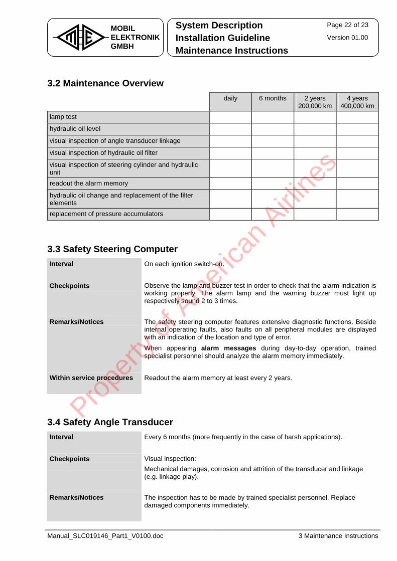
3.2 Maintenance Overview daily 6 months 2 years
200,000 km 4 years
400,000 km lamp test •
hydraulic oil level •
visual inspection of angle transducer linkage •
visual inspection of hydraulic oil filter •
visual inspection of steering cylinder and hydraulic unit
•
readout the alarm memory •
hydraulic oil change and replacement of the filter elements
•
replacement of pressure accumulators •
3.3 Safety Steering Computer Interval On each ignition switch-on.
Checkpoints Observe the lamp and buzzer test in order to check that the alarm indication is
working properly. The alarm lamp and the warning buzzer must light up respectively sound 2 to 3 times.
Remarks/Notices The safety steering computer features extensive diagnostic functions. Beside internal operating faults, also faults on all peripheral modules are displayed with an indication of the location and type of error. When appearing alarm messages during day-to-day operation, trained specialist personnel should analyze the alarm memory immediately.
Within service procedures Readout the alarm memory at least every 2 years.
3.4 Safety Angle Transducer Interval Every 6 months (more frequently in the case of harsh applications).
Checkpoints Visual inspection:
Mechanical damages, corrosion and attrition of the transducer and linkage (e.g. linkage play).
Remarks/Notices The inspection has to be made by trained specialist personnel. Replace damaged components immediately.
Prope
rty o
f Am
erica
n Airli
nes
System Description Page 23 of 23
Installation Guideline Version 01.00 MOBILELEKTRONIKGMBH Maintenance Instructions
Manual_SLC019146_Part1_V0100.doc 3 Maintenance Instructions
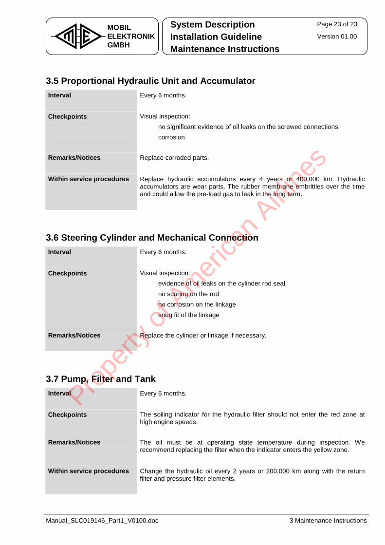
3.5 Proportional Hydraulic Unit and Accumulator Interval Every 6 months.
Checkpoints Visual inspection:
• no significant evidence of oil leaks on the screwed connections • corrosion
Remarks/Notices Replace corroded parts.
Within service procedures Replace hydraulic accumulators every 4 years or 400,000 km. Hydraulic
accumulators are wear parts. The rubber membrane embrittles over the time and could allow the pre-load gas to leak in the long term.
3.6 Steering Cylinder and Mechanical Connection Interval Every 6 months.
Checkpoints Visual inspection:
• evidence of oil leaks on the cylinder rod seal • no scoring on the rod • no corrosion on the linkage • snug fit of the linkage
Remarks/Notices Replace the cylinder or linkage if necessary.
3.7 Pump, Filter and Tank Interval Every 6 months.
Checkpoints The soiling indicator for the hydraulic filter should not enter the red zone at
high engine speeds.
Remarks/Notices The oil must be at operating state temperature during inspection. We recommend replacing the filter when the indicator enters the yellow zone.
Within service procedures Change the hydraulic oil every 2 years or 200,000 km along with the return
filter and pressure filter elements.
Prope
rty o
f Am
erica
n Airli
nes

Prope
rty o
f Am
erica
n Airli
nes
MOBILELEKTRONIKGMBH
Bössingerstraße 33 D-74243 Langenbeutingen � +49 (0) 7946 / 9194 - 0 FAX +49 (0) 7946 / 9194 - 130 http://www.mobil-elektronik.com
System Documentation - Part 2 Project-Specific Documentation Functional Description
Electro-Hydraulic Auxiliary Steering System
for Rear Axles
Type: SLC 019 146
Prope
rty o
f Am
erica
n Airli
nes
Project-Specific Documentation Page 2 of 18
Functional Description Version 01.00 MOBILELEKTRONIKGMBH List of Parameters
Manual_SLC019146_Part2_V0100.doc 0 List of Figures
Table of Contents List of Figures .............................................................................................. 3
History .......................................................................................................... 4
1 General ...................................................................................................... 5
1.1 Safety Notes............................................................................................................. 5
2 System Structure ...................................................................................... 6
2.1 Scope of Delivery MOBIL ELEKTRONIK................................................................ 6
2.2 Project-Specific System Diagram .......................................................................... 7
3 Functional Description ............................................................................. 8
3.1 Operation Functions ............................................................................................... 8 3.1.1 Steering Programs ........................................................................................................................8 3.1.2 Overview of steering programs ...................................................................................................8 3.1.3 Steering Program Selection .........................................................................................................9 3.1.4 Axle Synchronization..................................................................................................................10 3.1.5 Speed Limitation .........................................................................................................................10
3.2 Process Functions ................................................................................................ 11 3.2.1 Switch-On Test ............................................................................................................................11 3.2.2 Alarm Lamp and Alarm Buzzer ..................................................................................................11 3.2.3 Speed-Dependent Steering Angle Reduction ..........................................................................11 3.2.4 Readjustment of the Locking Position .....................................................................................12 3.2.5 Evaluation of the Steering Angles.............................................................................................12 3.2.6 Monitoring Functions .................................................................................................................13 3.2.7 Parameters for the J1939 CAN Communication ......................................................................14
3.3 Error Response and Safety Concept Effectiveness ........................................... 15
4 Hydraulic Components ........................................................................... 16
4.1 Manual Emergency Activation on EHLA Plus................................................... 16
5 Description of the Input and Output Signals......................................... 17
5.1 Digital Inputs.......................................................................................................... 17
5.2 Digital Outputs....................................................................................................... 17
5.3 Analogue Inputs .................................................................................................... 17
5.4 PWM Outputs......................................................................................................... 17
5.5 CAN input signals ................................................................................................. 18
5.6 CAN output signals ............................................................................................... 18
Prope
rty o
f Am
erica
n Airli
nes
Project-Specific Documentation Page 3 of 18
Functional Description Version 01.00 MOBILELEKTRONIKGMBH List of Parameters
Manual_SLC019146_Part2_V0100.doc 0 List of Figures
List of Figures Figure 1 – Steering Programs ..............................................................................................................................8 Figure 2 – Operation Terminal .............................................................................................................................9 Figure 3 – Speed-Dependent Steering Angle Reduction.................................................................................11 Figure 4 – System Deviation Monitoring...........................................................................................................13
Prope
rty o
f Am
erica
n Airli
nes
Project-Specific Documentation Page 4 of 18
Functional Description Version 01.00 MOBILELEKTRONIKGMBH List of Parameters
Manual_SLC019146_Part2_V0100.doc 0 History
History File Manual_SLC019146_Part2_V0100.doc
01.00 2011-05-09 TH new document based on “Manual_EHLA-Multi_Std_Part 2_V0201.doc”
Version
Subject to technical modification.
Prope
rty o
f Am
erica
n Airli
nes
Project-Specific Documentation Page 5 of 18
Functional Description Version 01.00 MOBILELEKTRONIKGMBH List of Parameters
Manual_SLC019146_Part2_V0100.doc 1 General
1 General The system documentation EHLA (German: “Elektro-Hydraulische Lenk-Anlage”; electro-hydraulic steering system) comprises four parts:
1. System description, installation and maintenance 2. Project specific documentation
3. Commissioning and diagnostics 4. List of alarm codes
This part 2 contains the project-specific documentation on the relevant customer application. For defined characters and abbreviations, see part 1 of the system documentation.
1.1 Safety Notes
Safety note: Please observe absolutely the safety notes from part 1 of the system documentation.
Prope
rty o
f Am
erica
n Airli
nes
Project-Specific Documentation Page 6 of 18
Functional Description Version 01.00 MOBILELEKTRONIKGMBH List of Parameters
Manual_SLC019146_Part2_V0100.doc 2 System Structure
2 System Structure
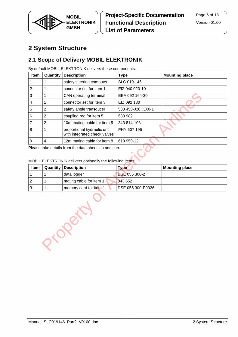
2.1 Scope of Delivery MOBIL ELEKTRONIK By default MOBIL ELEKTRONIK delivers these components:
Item Quantity Description Type Mounting place
1 1 safety steering computer SLC 019 146
2 1 connector set for item 1 EIZ 040 020-10
3 1 CAN operating terminal EEA 092 164-30
4 1 connector set for item 3 EIZ 092 130
5 2 safety angle transducer 533 450-J20K3X0-1
6 2 coupling rod for item 5 530 982
7 2 10m mating cable for item 5 343 814-103
8 1 proportional hydraulic unit with integrated check valves
PHY 607 195
9 4 12m mating cable for item 8 610 950-12
Please take details from the data sheets in addition.
MOBIL ELEKTRONIK delivers optionally the following items:
Item Quantity Description Type Mounting place
1 1 data logger DSE 055 300-2
2 1 mating cable for item 1 343 552
3 1 memory card for item 1 DSE 055 300-E0026
Prope
rty o
f Am
erica
n Airli
nes
Project-Specific Documentation Page 7 of 18
Functional Description Version 01.00 MOBILELEKTRONIKGMBH List of Parameters
Manual_SLC019146_Part2_V0100.doc 2 System Structure
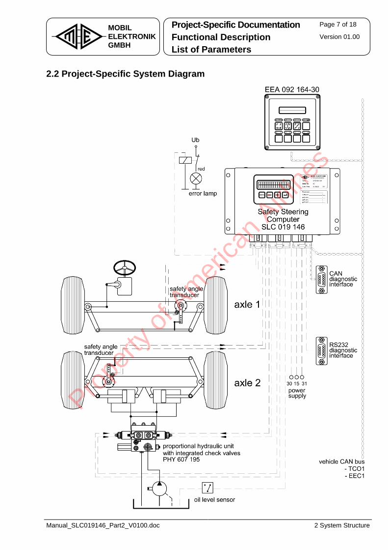
2.2 Project-Specific System Diagram
Prope
rty o
f Am
erica
n Airli
nes
Project-Specific Documentation Page 8 of 18
Functional Description Version 01.00 MOBILELEKTRONIKGMBH List of Parameters
Manual_SLC019146_Part2_V0100.doc 3 Functional Description
3 Functional Description Part 1 of the system documentation describes the basic system function. The following functional descriptions are covering the various controls and monitoring mechanisms in more detail.
3.1 Operation Functions
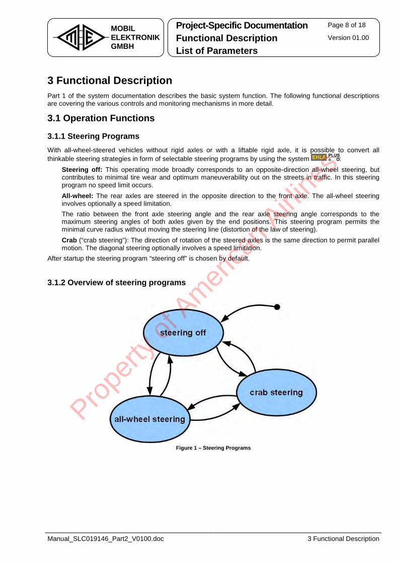
3.1.1 Steering Programs With all-wheel-steered vehicles without rigid axles or with a liftable rigid axle, it is possible to convert all thinkable steering strategies in form of selectable steering programs by using the system :• Steering off: This operating mode broadly corresponds to an opposite-direction all-wheel steering, but
contributes to minimal tire wear and optimum maneuverability out on the streets in traffic. In this steering program no speed limit occurs.
• All-wheel: The rear axles are steered in the opposite direction to the front axle. The all-wheel steering involves optionally a speed limitation. The ratio between the front axle steering angle and the rear axle steering angle corresponds to the maximum steering angles of both axles given by the end positions. This steering program permits the minimal curve radius without moving the steering line (distortion of the law of steering).
• Crab (“crab steering”): The direction of rotation of the steered axles is the same direction to permit parallel motion. The diagonal steering optionally involves a speed limitation.
After startup the steering program “steering off” is chosen by default.
3.1.2 Overview of steering programs
Figure 1 – Steering Programs
Prope
rty o
f Am
erica
n Airli
nes
Project-Specific Documentation Page 9 of 18
Functional Description Version 01.00 MOBILELEKTRONIKGMBH List of Parameters
Manual_SLC019146_Part2_V0100.doc 3 Functional Description
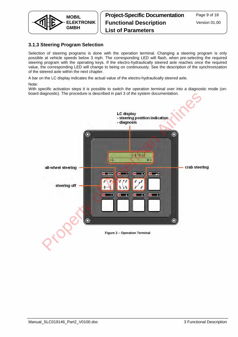
3.1.3 Steering Program Selection Selection of steering programs is done with the operation terminal. Changing a steering program is only possible at vehicle speeds below 3 mph. The corresponding LED will flash, when pre-selecting the required steering program with the operating keys. If the electro-hydraulically steered axle reaches once the required value, the corresponding LED will change to being on continuously. See the description of the synchronization of the steered axle within the next chapter. A bar on the LC display indicates the actual value of the electro-hydraulically steered axle. Note: With specific activation steps it is possible to switch the operation terminal over into a diagnostic mode (on-board diagnostic). The procedure is described in part 3 of the system documentation.
Figure 2 – Operation Terminal
Prope
rty o
f Am
erica
n Airli
nes
Project-Specific Documentation Page 10 of 18
Functional Description Version 01.00 MOBILELEKTRONIKGMBH List of Parameters
Manual_SLC019146_Part2_V0100.doc 3 Functional Description
3.1.4 Axle Synchronization In general, at vehicle standstill there is no movement of the electro-hydraulically steered rear axle without intentional operation by the driver. Depending on the system design, however, sudden centering of the rear axle may possible in several operating conditions, e.g. turning off the vehicle or system malfunction. See also chapter 3.3. If the angle of the electro-hydraulically steered rear axle already matches the required angle specified by the steering program after activating the system, the rear axle can be steered immediately. By changing the steering strategy, e.g. changeover from all-wheel steering to crab steering, there is no immediate change in the rear axle angle when the vehicle is at a standstill. The rear axle must be synchronized using one of the following operating steps: • Synchronization on starting:
The rear axle synchronizes on starting with an increasing distance travelled and reaches the required value after a few meters.
• Synchronization or capturing of the rear axle with the steering wheel: The rear axle synchronizes during a movement of the steering wheel in any direction. If the required value is reached in this process, the synchronization process is completed straight-ahead away (rear axle is captured).
• Synchronization via the steering program selection keys: The rear axle is moving in the direction of the specified position for the duration of the operating procedure. Once you release the button, the rear axle will remain stationary. Continue the synchronization process by holding down the steering program selection key again.
3.1.5 Speed Limitation In the steering program “steering off”, the vehicle speed is not limited. In all other steering programs, the vehicle speed is limited optionally. The signal output chosen with the parameter P_165 is indicating a speed limitation to the vehicle. The speed threshold at which to start limitation is to set in parameter P_079.
A recognized malfunction by the steering computer will result normally in a speed limitation too. A speed limitation is annulled, if it is possible to hold the axle in the straight-ahead position.
Prope
rty o
f Am
erica
n Airli
nes
Project-Specific Documentation Page 11 of 18
Functional Description Version 01.00 MOBILELEKTRONIKGMBH List of Parameters
Manual_SLC019146_Part2_V0100.doc 3 Functional Description
3.2 Process Functions
3.2.1 Switch-On Test After switching on the steering computer (this is normally after switching on the ignition on the vehicle), the steering system conducts a test of the connected lamps and buzzers. All connected lamps and buzzers are actuated for approx. 2.5 seconds and will flash once. If the system is fitted with the redundant fuse, the alarm lamp lights up permanently during the test. In vehicles with a relay for the combined switching of the alarm lamp and the mass of the solenoid valves, the alarm lamp is activated once on start up.
3.2.2 Alarm Lamp and Alarm Buzzer System alarms are indicated with an alarm lamp, e.g. if the axle has failed due to a malfunction. Occurred alarms are active until "ignition off", independently whether the cause of the alarm still exists. If the vehicle is in motion when the alarm occurs, the alarm buzzer sounds too. The alarm buzzer also sounds in case that there is no complete breakdown of the steering computer, when driving away during an alarm status.
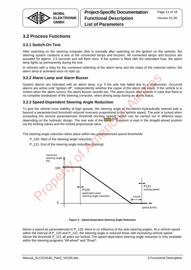
3.2.3 Speed-Dependent Steering Angle Reduction To give the vehicle more stability at high speeds, the steering angle of the electro-hydraulically steered axle is beyond a parameterized threshold reduced inversely proportional to the vehicle speed. The axle is locked when exceeding the second parameterized threshold (locking speed), which can be carried out in different ways depending on the hydraulic design. The rear axle of the system is kept in the straight-ahead position via the locking valves and the locked proportional valve. The steering angle reduction takes place within two parameterized speed thresholds: • P_120: Start of the steering angle reduction • P_121: End of the steering angle reduction (locking)
maximum steering angle[%]
0
100
P120 application point steering angle reduction 5 km/h
P121 locking speed
speed [km/h]
Figure 3 – Speed-Dependent Steering Angle Reduction Below a speed as parameterized in P_120, there is no influence of the axle steering angles. At a vehicle speed within the interval of P_120 and P_121, the steering angle is reduced linear with increasing vehicle speed. Above the threshold P_121 all axles are locked. The speed dependent steering angle reduction is only available within the steering programs “All-wheel” and “Road”.
Prope
rty o
f Am
erica
n Airli
nes
Project-Specific Documentation Page 12 of 18
Functional Description Version 01.00 MOBILELEKTRONIKGMBH List of Parameters
Manual_SLC019146_Part2_V0100.doc 3 Functional Description
3.2.4 Readjustment of the Locking Position
At EHLA steering systems it is possible that the locking position is not completely leak-proof. On both proportional valves and switching valves (locking valves, bypass valves) may arise a leakage due to permanent one-sided strengths. Examples: The vehicle stands on a sloping surface. The vehicle is moving for a longer period in ruts.
In order to antagonize those circumstances, the steering system attempts to correct the axle with limited valve control. This adjustment begins with a deviation above 1° and ends with a deviation below 0.25°. The adjustment is limited on a valve control of 20% for a maximum of 2 seconds.
The adjustment is not done, if the angle measurement is faulty.
3.2.5 Evaluation of the Steering Angles The front axle angle and the angle of the steered axle are captured via angle transducers with 2 separate electric signals. The angle transducers are mounted over a suitable linkage to the axle and are rotating with the wheel turning. Preferably, mount the transducers direct on the pivot to measure directly the angle of the respective wheel.
Functionality: The angle measurement is reading the voltage (0V - 5V) of the first signal from an angle transducer and evaluates over 3 points of reference "left stop", "centre position" and "right stop" the angle of the axle. Values between the points of reference are linear interpolated. The second signal is used to check the signal developing of the first signal.
The voltage developing must result in increasing values when moving the axle from the left to the right. The second signal behaves opposite.
The measured angle at the mechanical stops corresponds to the angle of the curves-inner wheel, i.e. for both mechanical stops, the same angle is measured. This simplifies the internal model for the calculation of the angles between axles, containing however a deviation to the actual wheel angle. The deviation between actual wheel angle and the measured angle is a nonlinear coherence, which is relevant affected by the angle transducer linkage and the wheel alignment.
Affecting Adjustments: The reference values for the stop angles are specified in parameters:
• Angle of the front axle in P_018, unit [0,1°]
• Angle of the rear axle in P_016, unit [0,1°] The voltage values assigned to the angles are taught in and stored durably during the alignment.
Pro
perty
of A
mer
ican
Airline
s
Project-Specific Documentation Page 13 of 18
Functional Description Version 01.00 MOBILELEKTRONIKGMBH List of Parameters
Manual_SLC019146_Part2_V0100.doc 3 Functional Description
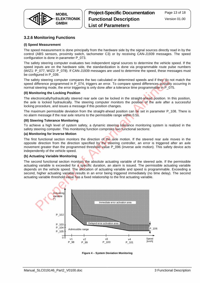
3.2.6 Monitoring Functions (I) Speed Measurement The speed measurement is done principally from the hardware side by the signal sources directly read in by the control (ABS sensors, proximity switch, tachometer C3) or by receiving CAN-J1939 messages. The speed configuration is done in parameter P_073. The safety steering computer evaluates two independent signal sources to determine the vehicle speed. If the speed inputs are on the hardware side, the standardization is done via programmable route pulse numbers (WIZ1: P_077, WIZ2: P_078). If CAN-J1939 messages are used to determine the speed, these messages must be configured in P_039. The safety steering computer compares the two calculated or determined speeds and if they do not match the speed difference programmed in P_074, triggers an error. To compare speed differences possibly occurring in normal steering mode, the error triggering is only done after a tolerance time programmable in P_075. (II) Monitoring the Locking Position The electronically/hydraulically steered rear axle can be locked in the straight-ahead position. In this position, the axle is locked hydraulically. The steering computer monitors the position of the axle after a successful locking procedure, and issues a message if this position changes. The maximum permissible deviation from the straight-ahead position can be set in parameter P_108. There is no alarm message if the rear axle returns to the permissible range within 0.5s. (III) Steering Tolerance Monitoring To achieve a high level of system safety, a dynamic steering tolerance monitoring system is realized in the safety steering computer. This monitoring function comprises two functional sections: (a) Monitoring for Inverse Motion The first functional section monitors the direction of the axle motion. If the steered rear axle moves in the opposite direction from the direction specified by the steering controller, an error is triggered after an axle movement greater than the programmed threshold value P_096 (inverse axle motion). This safety device acts independently of the vehicle speed. (b) Actuating Variable Monitoring The second functional section monitors the absolute actuating variable of the steered axle. If the permissible actuating variable is exceeded for a specific duration, an alarm is issued. The permissible actuating variable depends on the vehicle speed. The allocation of actuating variable and speed is programmable. Exceeding a second, higher actuating variable results in an error being triggered immediately (no time delay). The second actuating variable threshold value has a fixed relationship to the first actuating variable.
Delayed error activation area
0
P_102
P_103P_104P_105
v1P_98
v2P_99
v3P_100
v4P_101
Admissible range
Immediate error activation area
Actuatingvariable[°]
Speed [km/h]
P_106
Figure 4 – System Deviation Monitoring
Prope
rty o
f Am
erica
n Airli
nes
Project-Specific Documentation Page 14 of 18
Functional Description Version 01.00 MOBILELEKTRONIKGMBH List of Parameters
Manual_SLC019146_Part2_V0100.doc 3 Functional Description
(IV) Monitoring the Parameterization The steering computer is largely adaptable to the steering system via parameters. These parameters are changeable via the CAN diagnostic terminal or via the service software WinPCS. To assure the consistency of the parameterization, the values for the parameters P_032 to P_511 are checked and maintained by a signature in parameter P_033. During startup, the steering computer checks that the parameterization matches the signature and indicates an alarm code “031-19-0” at any variations. The first 5 minutes after switch on has no impact on the steering characteristics. The alarm message acts as a warning (alarm priority 0). During this time, it is possible to test new parameter settings on the vehicle. After 5 minutes, the alarm priority will be increased. The alarm code is then "031-19-1". The steering goes to the error status and locks all axles in the straight-ahead position. Leaving this status is only possible by switching the steering computer (ignition) on and off. (V) Actuator Test The actuator test is provided for function control of certain system components which will not be used in normal operation but which operation is important in case of malfunction. The test is to enable via the parameter P_035.
The actuator test is provided for the function control of the locking function of the stop valve. Therefore, an axle type with stop valve is to set in parameter P_049. The test starts only amongst others at vehicle standstill and running engine. (VI) Other Monitoring Functions To guarantee a reliable work of the safety steering system, it is possible besides the values described so far, to monitor the following states optionally: (a) Battery Charge Check This must be active (+24V) to determine the start of the pressure build-up and to avoid loading the battery unnecessarily when the engine is not running. (b) Oil Filter Monitoring This must be active (+24V) to monitor the correct function of the filter and to issue a servicing message. (c) Oil Level This must be active (+24V) to monitor a minimum reserve in the tank for the hydraulic oil for the steering system.
3.2.7 Parameters for the J1939 CAN Communication The parameters P_039 to P_042 define the J1939 CAN messages to receive and to send by the steering computer. See the contents explained in more detail in the customer parameter list. In addition, for diagnostic purposes, it is possible that the steering computer issues diagnostics data on a cyclical basis. To be able to transmit multiple data records, a multiplexed message (one data record per cycle) is used to provide them. The diagnostic data will be sent after receiving a request message. Pro
perty
of A
mer
ican
Airline
s
Project-Specific Documentation Page 15 of 18
Functional Description Version 01.00 MOBILELEKTRONIKGMBH List of Parameters
Manual_SLC019146_Part2_V0100.doc 3 Functional Description
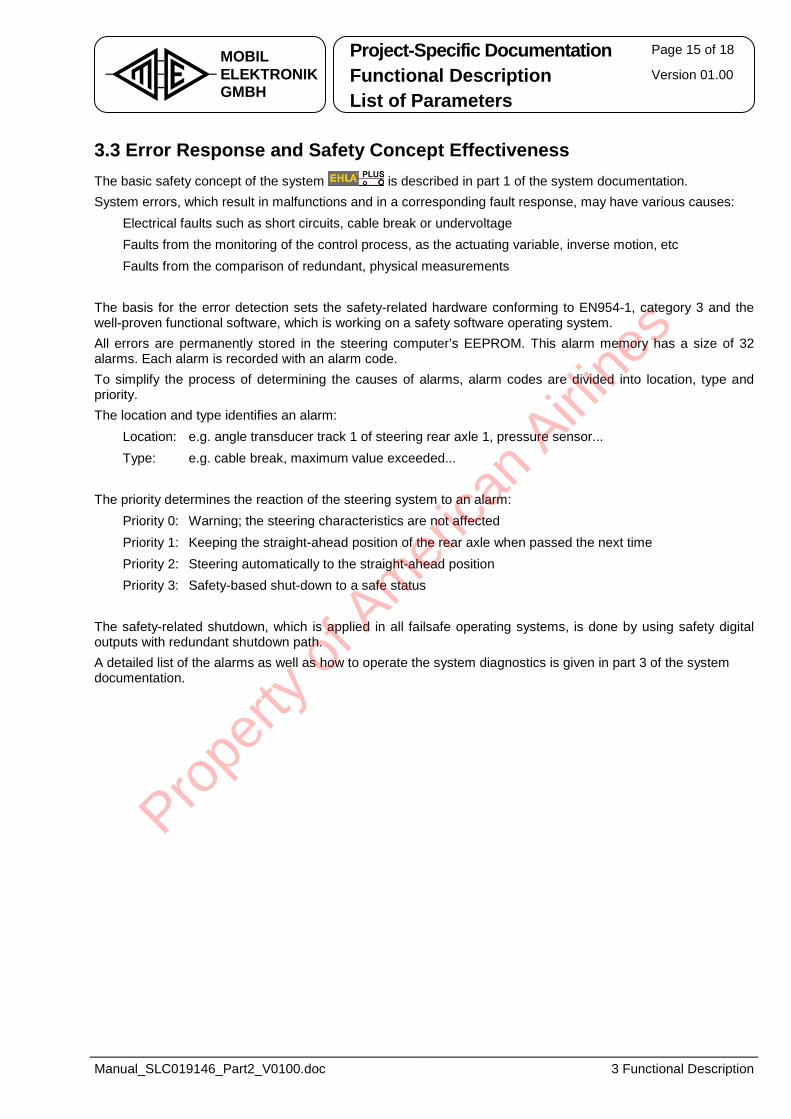
3.3 Error Response and Safety Concept Effectiveness The basic safety concept of the system is described in part 1 of the system documentation. System errors, which result in malfunctions and in a corresponding fault response, may have various causes: • Electrical faults such as short circuits, cable break or undervoltage • Faults from the monitoring of the control process, as the actuating variable, inverse motion, etc • Faults from the comparison of redundant, physical measurements The basis for the error detection sets the safety-related hardware conforming to EN954-1, category 3 and the well-proven functional software, which is working on a safety software operating system. All errors are permanently stored in the steering computer’s EEPROM. This alarm memory has a size of 32 alarms. Each alarm is recorded with an alarm code. To simplify the process of determining the causes of alarms, alarm codes are divided into location, type and priority. The location and type identifies an alarm: • Location: e.g. angle transducer track 1 of steering rear axle 1, pressure sensor... • Type: e.g. cable break, maximum value exceeded... The priority determines the reaction of the steering system to an alarm: • Priority 0: Warning; the steering characteristics are not affected • Priority 1: Keeping the straight-ahead position of the rear axle when passed the next time • Priority 2: Steering automatically to the straight-ahead position • Priority 3: Safety-based shut-down to a safe status The safety-related shutdown, which is applied in all failsafe operating systems, is done by using safety digital outputs with redundant shutdown path. A detailed list of the alarms as well as how to operate the system diagnostics is given in part 3 of the system documentation.
Prope
rty o
f Am
erica
n Airli
nes
Project-Specific Documentation Page 16 of 18
Functional Description Version 01.00 MOBILELEKTRONIKGMBH List of Parameters
Manual_SLC019146_Part2_V0100.doc 4 Hydraulic Components
4 Hydraulic Components
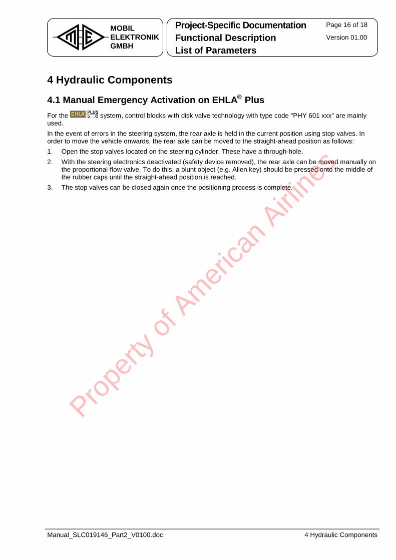
4.1 Manual Emergency Activation on EHLA Plus For the system, control blocks with disk valve technology with type code "PHY 601 xxx" are mainly used. In the event of errors in the steering system, the rear axle is held in the current position using stop valves. In order to move the vehicle onwards, the rear axle can be moved to the straight-ahead position as follows: 1. Open the stop valves located on the steering cylinder. These have a through-hole. 2. With the steering electronics deactivated (safety device removed), the rear axle can be moved manually on
the proportional-flow valve. To do this, a blunt object (e.g. Allen key) should be pressed onto the middle of the rubber caps until the straight-ahead position is reached.
3. The stop valves can be closed again once the positioning process is complete.
Prope
rty o
f Am
erica
n Airli
nes
Project-Specific Documentation Page 17 of 18
Functional Description Version 01.00 MOBILELEKTRONIKGMBH List of Parameters
Manual_SLC019146_Part2_V0100.doc 5 Description of the Input and Output Signals
5 Description of the Input and Output Signals
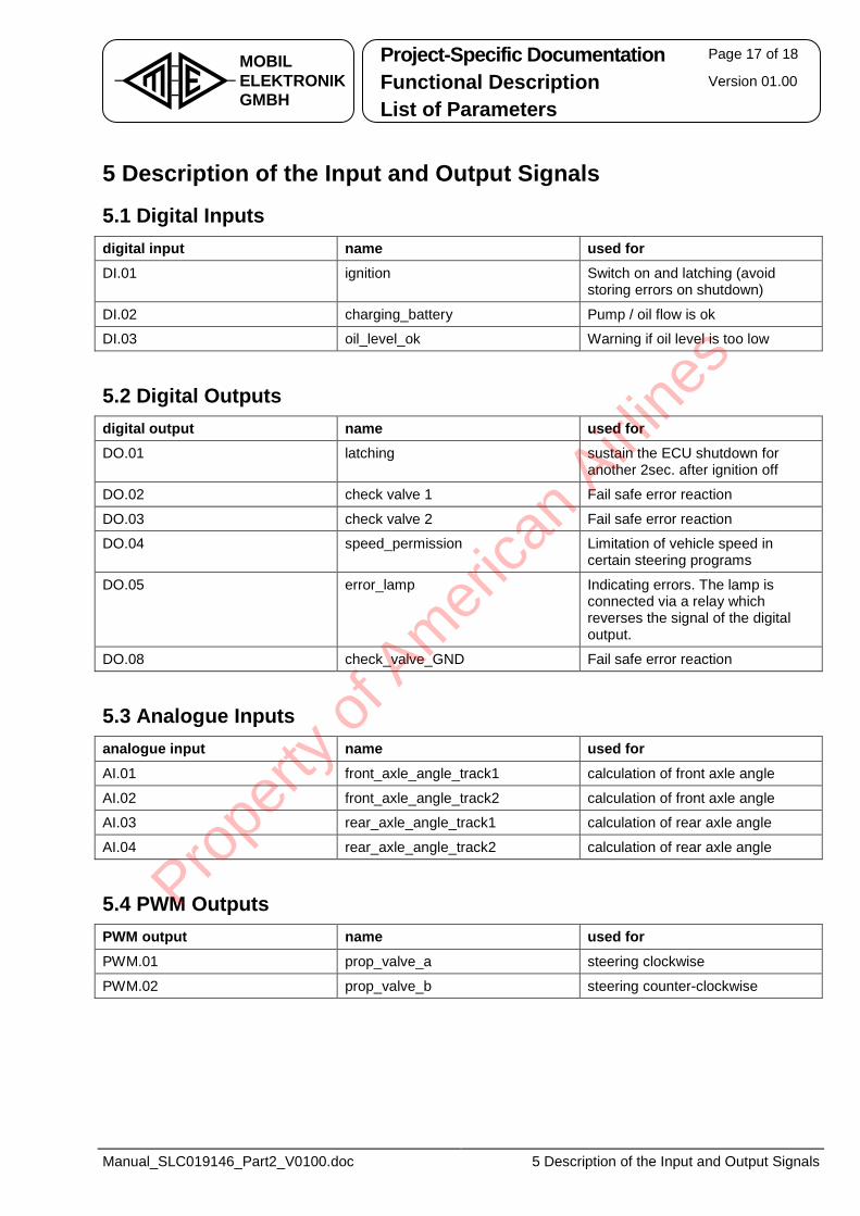
5.1 Digital Inputs digital input name used for DI.01 ignition Switch on and latching (avoid
storing errors on shutdown)
DI.02 charging_battery Pump / oil flow is ok
DI.03 oil_level_ok Warning if oil level is too low
5.2 Digital Outputs digital output name used for DO.01 latching sustain the ECU shutdown for
another 2sec. after ignition off
DO.02 check valve 1 Fail safe error reaction
DO.03 check valve 2 Fail safe error reaction
DO.04 speed_permission Limitation of vehicle speed in certain steering programs
DO.05 error_lamp Indicating errors. The lamp is connected via a relay which reverses the signal of the digital output.
DO.08 check_valve_GND Fail safe error reaction
5.3 Analogue Inputs analogue input name used for AI.01 front_axle_angle_track1 calculation of front axle angle
AI.02 front_axle_angle_track2 calculation of front axle angle
AI.03 rear_axle_angle_track1 calculation of rear axle angle
AI.04 rear_axle_angle_track2 calculation of rear axle angle
5.4 PWM Outputs PWM output name used for PWM.01 prop_valve_a steering clockwise
PWM.02 prop_valve_b steering counter-clockwise
Prope
rty o
f Am
erica
n Airli
nes
Project-Specific Documentation Page 18 of 18
Functional Description Version 01.00 MOBILELEKTRONIKGMBH List of Parameters
Manual_SLC019146_Part2_V0100.doc 5 Description of the Input and Output Signals
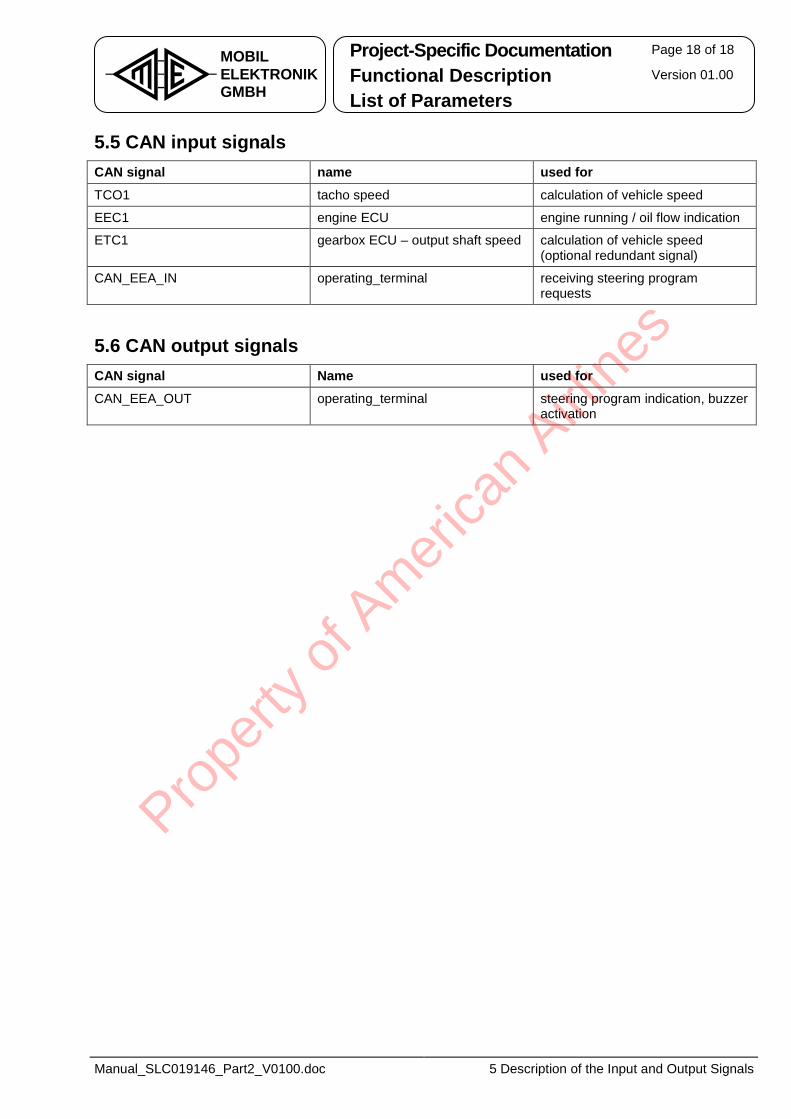
5.5 CAN input signals CAN signal name used for TCO1 tacho speed calculation of vehicle speed
EEC1 engine ECU engine running / oil flow indication
ETC1 gearbox ECU – output shaft speed calculation of vehicle speed (optional redundant signal)
CAN_EEA_IN operating_terminal receiving steering program requests
5.6 CAN output signals CAN signal Name used for CAN_EEA_OUT operating_terminal steering program indication, buzzer
activation
Prope
rty o
f Am
erica
n Airli
nes
MOBILELEKTRONIKGMBH
Bössingerstraße 33 D-74243 Langenbeutingen � +49 (0) 7946 / 9194 - 0 FAX +49 (0) 7946 / 9194 - 130 http://www.mobil-elektronik.com
System Documentation - Part 3 Commissioning Diagnostics and Alarm Memory Parameterization
Electro-Hydraulic Auxiliary Steering System
for Rear Axles
Type: SLC 019 146
Prope
rty o
f Am
erica
n Airli
nes
Commissioning Page 2 of 40
Diagnostics and Alarm Memory Version 01.00 MOBILELEKTRONIKGMBH Parameterization
Manual_SLC019146_Part3_V0100.doc 0 History
Table of Contents History .......................................................................................................... 4
1 General ...................................................................................................... 5
1.1 Documentation ........................................................................................................ 5
1.2 Safety Notes............................................................................................................. 5
2 Tools for Diagnostics................................................................................ 6
2.1 On-Board Diagnostic............................................................................................... 6 2.1.1 Keyboard Layout of the On-Board-Diagnostic...........................................................................6 2.1.2 Menu Structure of the On-Board Diagnostic..............................................................................7
2.2 PC Service Software WinPCS................................................................................. 8 2.2.1 Program Window of the WinPCS.................................................................................................8 2.2.2 PC Requirements and Cable Set .................................................................................................9 2.2.3 Installation .....................................................................................................................................9 2.2.4 First Run and Settings..................................................................................................................9
2.3 CAN Diagnostic Terminal ..................................................................................... 10 2.3.1 Keyboard Layout of the CAN Diagnostic Terminal..................................................................10 2.3.2 Handling the CAN Diagnostic Terminal ....................................................................................11
2.4 Operation Terminal................................................................................................ 12 2.4.1 Keyboard Layout of the Operation Terminal............................................................................12 2.4.2 Menu Structure of the Operation Terminal...............................................................................13
3 Commissioning ....................................................................................... 14
3.1 Requirements ........................................................................................................ 14
3.2 Preparations and Notes ........................................................................................ 15 3.2.1 Verifying the Electric Installation ..............................................................................................15 3.2.2 Calibrating the Safety Angle Transducer .................................................................................15 3.2.3 Rotational Direction of the Output Voltage ..............................................................................15 3.2.4 Cable Break Range of the Safety Angle Transducer ...............................................................15
3.3 Commissioning using On-Board Diagnostic ...................................................... 16 3.3.1 Activating the Alignment............................................................................................................16 3.3.2 Alignment Menu Structure Overview ........................................................................................17 3.3.3 Selecting the Axle for Alignment...............................................................................................18 3.3.4 Selecting an Axle respectively a Position for Alignment........................................................18 3.3.5 Alignment of the Axle Positions................................................................................................19 3.3.6 Quitting Alignment......................................................................................................................20
3.4 Commissioning using WinPCS ............................................................................ 21
3.5 Commissioning using CAN Diagnostic Terminal ............................................... 21
Prope
rty o
f Am
erica
n Airli
nes
Commissioning Page 3 of 40
Diagnostics and Alarm Memory Version 01.00 MOBILELEKTRONIKGMBH Parameterization
Manual_SLC019146_Part3_V0100.doc 0 History
3.6 Commissioning using Operation Terminal ......................................................... 21
3.7 Establishing Steering Operation and Test Drive ................................................ 22
3.8 Checking the Alarm Memory ................................................................................ 22
4 Reading and Clearing the Alarm Memory.............................................. 23
4.1 Handling the Alarm Memory using On-Board Diagnostic.................................. 23 4.1.1 Display of Current Alarms at Malfunction ................................................................................23 4.1.2 Reading Out the Alarm Memory ................................................................................................23 4.1.3 Clearing the Alarm Memory .......................................................................................................24
4.2 Handling the Alarm Memory using WinPCS ....................................................... 25 4.2.1 Reading Out the Alarm Memory ................................................................................................25 4.2.2 Clearing the Alarm Memory .......................................................................................................25
4.3 Handling the Alarm Memory using CAN Diagnostic Terminal .......................... 26
4.4 Handling the Alarm Memory using Operation Terminal..................................... 26
5 Operating Data Display........................................................................... 27
5.1 Operating Data Display using On-Board Diagnostic.......................................... 27 5.1.1 Display in Startup, Software Versions ......................................................................................27 5.1.2 Display in Alarm Free Condition (Normal Operation)..............................................................28 5.1.3 Displaying the Operating Data...................................................................................................29 5.1.4 Displaying the States of the Inputs and Outputs.....................................................................30
5.2 Operating Data Display using WinPCS................................................................ 31 5.2.1 Display the State of the Inputs and Outputs ............................................................................31 5.2.2 Displaying the Software Version ...............................................................................................32
5.3 Operating Data Display using CAN Diagnostic Terminal................................... 33
5.4 Operating Data Display using Operating Terminal............................................. 33
6 System Parameterization........................................................................ 34
6.1 Handling the Parameters using On-Board Diagnostic ....................................... 34 6.1.1 Reading Out Parameters Successively ....................................................................................34 6.1.2 Editing and Changing Parameters ............................................................................................35
6.2 Handling the Parameters using WinPCS............................................................. 36
6.3 Handling the Parameters using CAN Diagnostic Terminal................................ 37
6.4 Handling the Parameters using Operation Terminal.......................................... 37
7 Data Recording........................................................................................ 38
7.1 Data Recording single values .............................................................................. 38
7.2 Graphical display - Oscilloscope ......................................................................... 39
Prope
rty o
f Am
erica
n Airli
nes
Commissioning Page 4 of 40
Diagnostics and Alarm Memory Version 01.00 MOBILELEKTRONIKGMBH Parameterization
Manual_SLC019146_Part3_V0100.doc 0 History
History File Manual_SLC019146_Part3_V0100.doc
Version 01.00 2011-05-09 TH new document based on “Manual_EHLA-Multi_Std_Part 3_V0203.doc”
Subject to technical modification.
Prope
rty o
f Am
erica
n Airli
nes
Commissioning Page 5 of 40
Diagnostics and Alarm Memory Version 01.00 MOBILELEKTRONIKGMBH Parameterization
Manual_SLC019146_Part3_V0100.doc 1 General
1 General
1.1 Documentation The system documentation EHLA (German: “Elektro-Hydraulische Lenk-Anlage”; electro-hydraulic steering system) comprises four parts:
1. System description, installation and maintenance
2. Project specific documentation 3. Commissioning and diagnostics
4. List of alarm codes This third part on hand describes the commissioning and diagnostics of the steering system. Part 3 and part 4 are meant for service activities. For defined characters and abbreviations, see part 1 of the system documentation.
1.2 Safety Notes
Safety note: Please observe absolutely the safety notes from part 1 of the system documentation.
Prope
rty o
f Am
erica
n Airli
nes
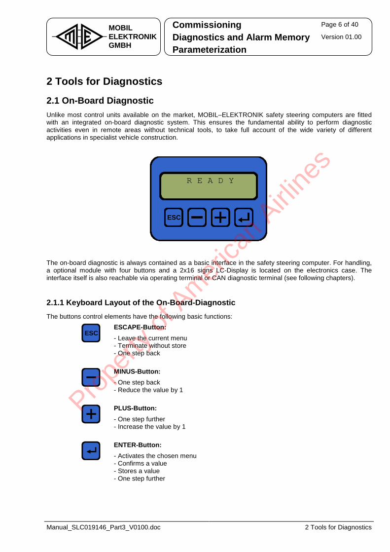
Commissioning Page 6 of 40
Diagnostics and Alarm Memory Version 01.00 MOBILELEKTRONIKGMBH Parameterization
Manual_SLC019146_Part3_V0100.doc 2 Tools for Diagnostics
2 Tools for Diagnostics
2.1 On-Board Diagnostic Unlike most control units available on the market, MOBIL–ELEKTRONIK safety steering computers are fitted with an integrated on-board diagnostic system. This ensures the fundamental ability to perform diagnostic activities even in remote areas without technical tools, to take full account of the wide variety of different applications in specialist vehicle construction.
ESC
R E A D Y
The on-board diagnostic is always contained as a basic interface in the safety steering computer. For handling, a optional module with four buttons and a 2x16 signs LC-Display is located on the electronics case. The interface itself is also reachable via operating terminal or CAN diagnostic terminal (see following chapters).
2.1.1 Keyboard Layout of the On-Board-Diagnostic The buttons control elements have the following basic functions:
ESCESCAPE-Button: - Leave the current menu - Terminate without store - One step back MINUS-Button: - One step back - Reduce the value by 1 PLUS-Button: - One step further - Increase the value by 1 ENTER-Button: - Activates the chosen menu - Confirms a value - Stores a value - One step further
Prope
rty o
f Am
erica
n Airli
nes
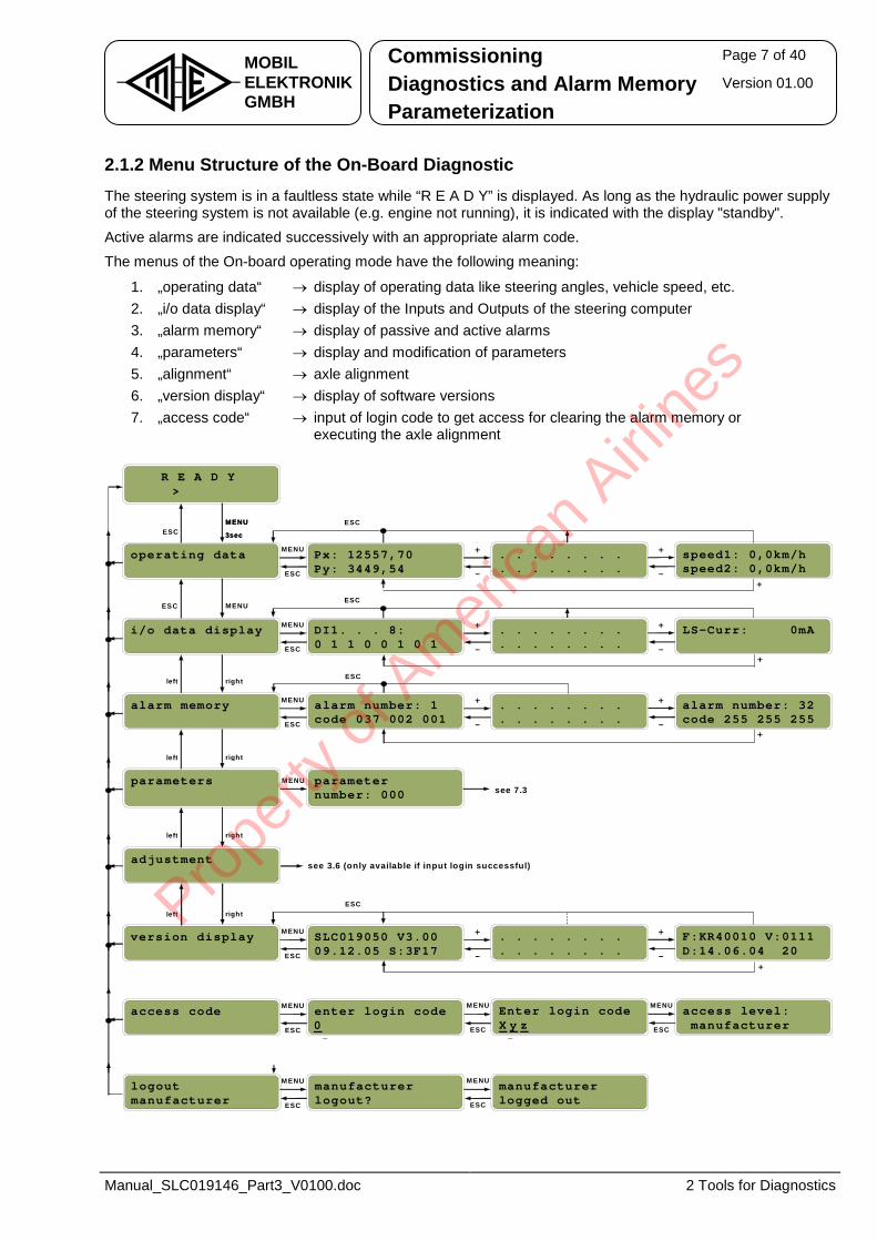
Commissioning Page 7 of 40
Diagnostics and Alarm Memory Version 01.00 MOBILELEKTRONIKGMBH Parameterization
Manual_SLC019146_Part3_V0100.doc 2 Tools for Diagnostics
2.1.2 Menu Structure of the On-Board Diagnostic The steering system is in a faultless state while “R E A D Y” is displayed. As long as the hydraulic power supply of the steering system is not available (e.g. engine not running), it is indicated with the display "standby". Active alarms are indicated successively with an appropriate alarm code.
The menus of the On-board operating mode have the following meaning:
1. „operating data“ → display of operating data like steering angles, vehicle speed, etc. 2. „i/o data display“ → display of the Inputs and Outputs of the steering computer 3. „alarm memory“ → display of passive and active alarms 4. „parameters“ → display and modification of parameters 5. „alignment“ → axle alignment 6. „version display“ → display of software versions 7. „access code“ → input of login code to get access for clearing the alarm memory or
executing the axle alignment
ESCMENU
3sec
ESC
R E A D Y>
operating data
alarm memory
parameters
adjustment
Px: 12557,70Py: 3449,54
alarm number: 1code 037 002 001
parameternumber: 000
. . . . . . . .
. . . . . . . .speed1: 0,0km/hspeed2: 0,0km/h
+
-
+
-
MENU
ESC
. . . . . . . .
. . . . . . . .alarm number: 32code 255 255 255
+
-
+
-
MENU
ESC
version display SLC019050 V3.0009.12.05 S:3F17
. . . . . . . .
. . . . . . . .F:KR40010 V:0111D:14.06.04 20
+
-
+
-
MENU
ESC
i/o data display DI1. . . 8:0 1 1 0 0 1 0 1
. . . . . . . .
. . . . . . . .LS-Curr: 0mA+
-
+
-
MENU
ESC
ESC
ESC
see 7.3
see 3.6 (only available if input login successful)
MENU
3sec
ESC MENU
left right
left right
left right
left rightESC
+
+
+
+
M ENU
logoutmanufacturer
manufacturerlogout?
manufacturerlogged out
M ENU
ESC
M ENU
ESC
access code enter login code 0-
Enter login codeX y z-
access level:manufacturer
M ENU
ESC
MENU
ESC
M ENU
ESC
Prope
rty o
f Am
erica
n Airli
nes
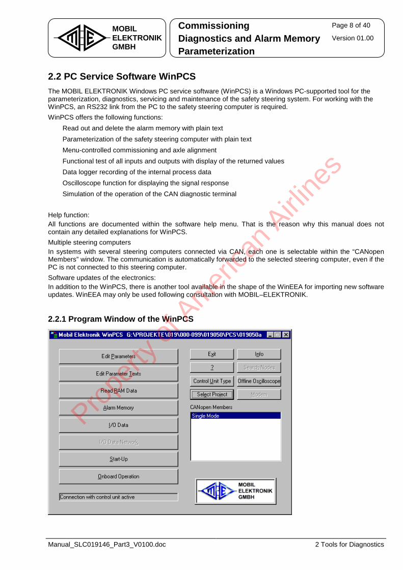
Commissioning Page 8 of 40
Diagnostics and Alarm Memory Version 01.00 MOBILELEKTRONIKGMBH Parameterization
Manual_SLC019146_Part3_V0100.doc 2 Tools for Diagnostics
2.2 PC Service Software WinPCS The MOBIL ELEKTRONIK Windows PC service software (WinPCS) is a Windows PC-supported tool for the parameterization, diagnostics, servicing and maintenance of the safety steering system. For working with the WinPCS, an RS232 link from the PC to the safety steering computer is required. WinPCS offers the following functions: • Read out and delete the alarm memory with plain text • Parameterization of the safety steering computer with plain text • Menu-controlled commissioning and axle alignment • Functional test of all inputs and outputs with display of the returned values • Data logger recording of the internal process data • Oscilloscope function for displaying the signal response • Simulation of the operation of the CAN diagnostic terminal Help function: All functions are documented within the software help menu. That is the reason why this manual does not contain any detailed explanations for WinPCS. Multiple steering computers In systems with several steering computers connected via CAN, each one is selectable within the “CANopen Members” window. The communication is automatically forwarded to the selected steering computer, even if the PC is not connected to this steering computer. Software updates of the electronics: In addition to the WinPCS, there is another tool available in the shape of the WinEEA for importing new software updates. WinEEA may only be used following consultation with MOBIL–ELEKTRONIK.
2.2.1 Program Window of the WinPCS
Prope
rty o
f Am
erica
n Airli
nes
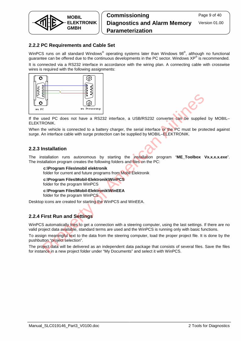
Commissioning Page 9 of 40
Diagnostics and Alarm Memory Version 01.00 MOBILELEKTRONIKGMBH Parameterization
Manual_SLC019146_Part3_V0100.doc 2 Tools for Diagnostics
2.2.2 PC Requirements and Cable Set WinPCS runs on all standard Windows® operating systems later than Windows 98®, although no functional guarantee can be offered due to the continuous developments in the PC sector. Windows XP® is recommended. It is connected via a RS232 interface in accordance with the wiring plan. A connecting cable with crosswise wires is required with the following assignments:
If the used PC does not have a RS232 interface, a USB/RS232 converter can be supplied by MOBIL–ELEKTRONIK. When the vehicle is connected to a battery charger, the serial interface or the PC must be protected against surge. An interface cable with surge protection can be supplied by MOBIL–ELEKTRONIK.
2.2.3 Installation The installation runs autonomous by starting the installation program “ME_Toolbox Vx.x.x.x.exe”. The installation program creates the following folders and files on the PC:
• c:\Program Files\mobil elektronik folder for current and future programs from Mobil Elektronik
• c:\Program Files\Mobil-Elektronik\WinPCS folder for the program WinPCS
• c:\Program Files\Mobil-Elektronik\WinEEA folder for the program WinPCS
Desktop icons are created for starting the WinPCS and WinEEA.
2.2.4 First Run and Settings WinPCS automatically tries to get a connection with a steering computer, using the last settings. If there are no valid project data available, standard terms are used and the WinPCS is running only with basic functions. To assign meaningful text to the data from the steering computer, load the proper project file. It is done by the pushbutton “project selection”. The project data will be delivered as an independent data package that consists of several files. Save the files for instance in a new project folder under “My Documents” and select it with WinPCS.
Prope
rty o
f Am
erica
n Airli
nes
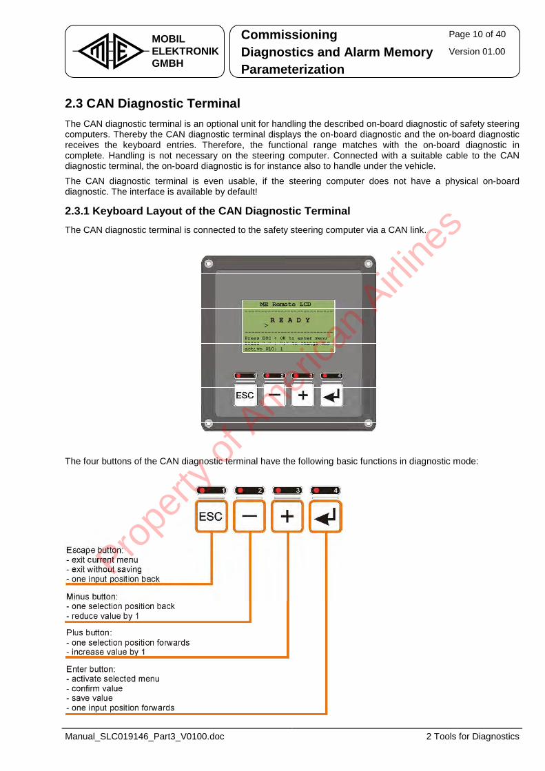
Commissioning Page 10 of 40
Diagnostics and Alarm Memory Version 01.00 MOBILELEKTRONIKGMBH Parameterization
Manual_SLC019146_Part3_V0100.doc 2 Tools for Diagnostics
2.3 CAN Diagnostic Terminal The CAN diagnostic terminal is an optional unit for handling the described on-board diagnostic of safety steering computers. Thereby the CAN diagnostic terminal displays the on-board diagnostic and the on-board diagnostic receives the keyboard entries. Therefore, the functional range matches with the on-board diagnostic in complete. Handling is not necessary on the steering computer. Connected with a suitable cable to the CAN diagnostic terminal, the on-board diagnostic is for instance also to handle under the vehicle.
The CAN diagnostic terminal is even usable, if the steering computer does not have a physical on-board diagnostic. The interface is available by default!
2.3.1 Keyboard Layout of the CAN Diagnostic Terminal The CAN diagnostic terminal is connected to the safety steering computer via a CAN link.
R E A D Y
The four buttons of the CAN diagnostic terminal have the following basic functions in diagnostic mode:
Prope
rty o
f Am
erica
n Airli
nes
Commissioning Page 11 of 40
Diagnostics and Alarm Memory Version 01.00 MOBILELEKTRONIKGMBH Parameterization
Manual_SLC019146_Part3_V0100.doc 2 Tools for Diagnostics
2.3.2 Handling the CAN Diagnostic Terminal After building up the connection of the CAN diagnostic terminal to the steering computer, the on-board diagnostic occurs on the CAN diagnostic terminal. A disturbed CAN connection or a switched off steering computer will cause the display “no connection”. Any keystroke on the CAN diagnostic terminal is directly transmitted to the steering computer, activating there the according function, for instance reading out the alarm memory. For handling the on-board diagnostic, see chapter 2.1. The CAN diagnostic terminal is switchable to another steering computer if there are several steering computers within the CAN network active:
• Press the button PLUS and MINUS at the same time. The on-board diagnostic is displayed smaller and accordant information are shown.
• Choose the new steering computer (SLC1 to SLC5) by pressing the PLUS or MINUS button. The respective on-board diagnostic is displayed directly.
• Press the button ESC or ENTER to switch back to the normal display to handle the steering computer.
Prope
rty o
f Am
erica
n Airli
nes
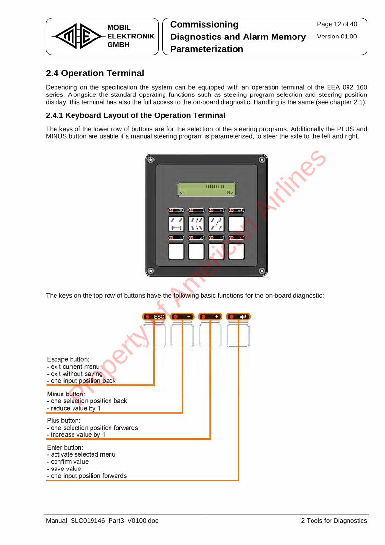
Commissioning Page 12 of 40
Diagnostics and Alarm Memory Version 01.00 MOBILELEKTRONIKGMBH Parameterization
Manual_SLC019146_Part3_V0100.doc 2 Tools for Diagnostics
2.4 Operation Terminal Depending on the specification the system can be equipped with an operation terminal of the EEA 092 160 series. Alongside the standard operating functions such as steering program selection and steering position display, this terminal has also the full access to the on-board diagnostic. Handling is the same (see chapter 2.1).
2.4.1 Keyboard Layout of the Operation Terminal The keys of the lower row of buttons are for the selection of the steering programs. Additionally the PLUS and MINUS button are usable if a manual steering program is parameterized, to steer the axle to the left and right.
The keys on the top row of buttons have the following basic functions for the on-board diagnostic:
Prope
rty o
f Am
erica
n Airli
nes
Commissioning Page 13 of 40
Diagnostics and Alarm Memory Version 01.00 MOBILELEKTRONIKGMBH Parameterization
Manual_SLC019146_Part3_V0100.doc 2 Tools for Diagnostics
2.4.2 Menu Structure of the Operation Terminal The menu structure of the operation terminal is subdivided into two main functions:
1. Displaying the steering position: The steering position display is indicating the current position of the steering axle as bar graph. Occurring failures in the steering system during the operation are indicated as plaintext and with an appropriate alarm code in place of the steering position display.
2. On-board diagnostic: After selecting the on-board diagnostic by pressing the MENU button, “R E A D Y” is displayed in case of a failure free steering system. Otherwise, active alarms are indicated successively with the appropriate alarm code. For handling the on-board diagnostic, see chapter 2.1.
Prope
rty o
f Am
erica
n Airli
nes
Commissioning Page 14 of 40
Diagnostics and Alarm Memory Version 01.00 MOBILELEKTRONIKGMBH Parameterization
Manual_SLC019146_Part3_V0100.doc 3 Commissioning
3 Commissioning During alignment (angle transducer alignment), the steering computer is saving the assignment of the respective angle transducer to the straight-ahead position respectively to the maximum left and right block position of the axle. The steering computer accesses the saved values during regular steering for calculating the axle angles. Therefore, the alignment is an important part of the commissioning.
Safety note: The axles are moving during alignment! Assure that no axle movement is possible during adjustment work within the swivel range. This could be done by switching of the hydraulic supply (engine off), by depressurization of existing accumulators or by locking the axle. Before alignment, the proper factory parameter set must be loaded to the steering computer!
3.1 Requirements The installation of the hydraulic and electrical components in accordance with the installation instructions must be complete and free of alarms. Specialist personnel trained in electrical engineering must carry out the commissioning. Basic knowledge of vehicle technology (CAN, etc.) is required. Execute the commissioning in the specified order of the following chapters. Changing the workflow can cause malfunctions. Modifying the system and its components or installing the steering system in other vehicle models without permission of MOBIL–ELEKTRONIK will invalidate the CE sign and all guarantees. In this case, the factory given warranties are invalid.
Prope
rty o
f Am
erica
n Airli
nes
Commissioning Page 15 of 40
Diagnostics and Alarm Memory Version 01.00 MOBILELEKTRONIKGMBH Parameterization
Manual_SLC019146_Part3_V0100.doc 3 Commissioning
3.2 Preparations and Notes
3.2.1 Verifying the Electric Installation Verify that all connections are according to the wiring diagram before connecting the power supply to the safety steering computer. Take special care that the power supply is correct and all other connections (except the digital inputs) are voltage-free. All hydraulic valves must be correctly assigned and existing pressure sensors correctly connected. Notes: • An external connection between the 0V load and 0V signal is not permitted! • Never remove plug connectors under voltage!
3.2.2 Calibrating the Safety Angle Transducer Ensure when using safety angle transducers with potentiometric measurement principle that sensors A are supplied by 5Vref and sensors B by 5Vext. In the straight-ahead position of the axle, the voltage of sensor A must be between 2350mV and 2650mV. Safety angle transducers using Hall technology with active signal output are supplied with 24V. The output voltages are also each approx. 2500mV ±150mV in the straight-ahead position. With third party products, observe the relevant manufacturer instructions in consultation with MOBIL–ELEKTRONIK.
3.2.3 Rotational Direction of the Output Voltage Voltage direction on sensor A: Rotation of the axle clockwise (to the right) ⇒ increasing voltage on sensor A Voltage direction on sensor B: Rotation of the axle clockwise (to the right) ⇒ decreasing voltage on sensor B
3.2.4 Cable Break Range of the Safety Angle Transducer To ensure cable break monitoring, with a maximum right movement of the axle, the voltage on sensor A must not exceed 4800mV, and with a maximum left movement, the voltage must not be lower than 200mV.
Prope
rty o
f Am
erica
n Airli
nes
Commissioning Page 16 of 40
Diagnostics and Alarm Memory Version 01.00 MOBILELEKTRONIKGMBH Parameterization
Manual_SLC019146_Part3_V0100.doc 3 Commissioning
3.3 Commissioning using On-Board Diagnostic
3.3.1 Activating the Alignment The on-board diagnostic is activated by pressing the ENTER button for at least 3 seconds. As soon as the display "operating data" appears, use the PLUS or MINUS button to select the menu item “access code”. There are further menu items available after entering the proper password. Select the menu item “alignment” with the PLUS or MINUS button and activate it with ENTER. You can quit the alignment any time with ESC. The password is intended to restrict the proceeding of the alignment to trained staff (trained staff can inquire the password at MOBIL–ELEKTRONIK).
There are different workflows possible for the alignment procedure:
1. Axle oriented alignment: With this expiration each axle is adjusted individually successively at the positions "middle", "left" and "right". This procedure corresponds to the available operational sequence. This kind of the alignment is favorable, if an angle transducer was exchanged and only this axle must again be adjusted.
2. Position oriented alignment: With this expiration all axles are adjusted successively at the same position. E.g. all axles are worked on and stored successively in the straight-ahead position, afterwards all axles on the “left” position etc.. This kind of the alignment is favorable, if all angle sensors must again be adjusted (first start up or exchange of steering computer).
3. Alignment with selectable axle and position: With this option the alignment of the axles can be determined completely freely, a certain sequence is not given. An individual position of an axle can be adjusted by this expiration separately. The completeness of the alignment is not guaranteed.
4. Reading out the alignment values: The adjusted values can be read out in this menu option during the operation of the alignment. Here the axles can be moved also manually to test purposes. By this separate point no inadvertent changes of the stored adjusted values are more possible.
Boundary conditions:
- The storage of the axle position effected now for each position and does not need to be confirmed to no more. So far storage for a complete angle sensor in three positions was caused.
- The selection of the stored values was realized as separate branch. Here the appropriate axle can be also moved.
Prope
rty o
f Am
erica
n Airli
nes
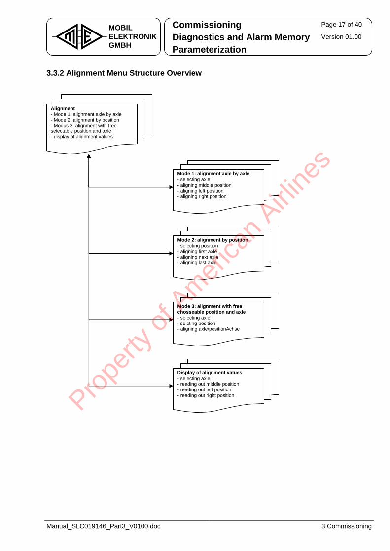
Commissioning Page 17 of 40
Diagnostics and Alarm Memory Version 01.00 MOBILELEKTRONIKGMBH Parameterization
Manual_SLC019146_Part3_V0100.doc 3 Commissioning
3.3.2 Alignment Menu Structure Overview
Alignment- Mode 1: alignment axle by axle - Mode 2: alignment by position - Modus 3: alignment with free selectable position and axle - display of alignment values
Mode 1: alignment axle by axle- selecting axle - aligning middle position - aligning left position - aligning right position
Mode 2: alignment by position- selecting position - aligning first axle - aligning next axle - aligning last axle
Mode 3: alignment with free chosseable position and axle - selecting axle - selcting position - aligning axle/positionAchse
Display of alignment values- selecting axle - reading out middle position - reading out left position - reading out right position Pro
perty
of A
mer
ican
Airline
s
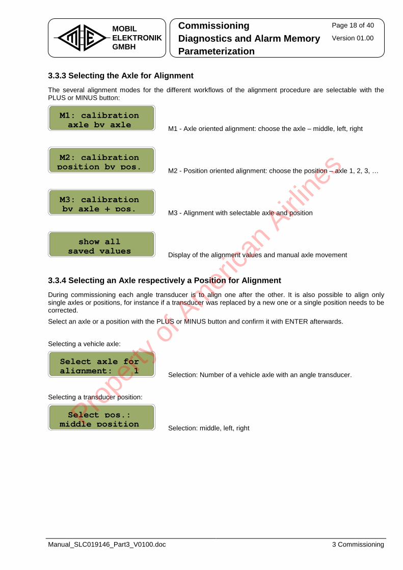
Commissioning Page 18 of 40
Diagnostics and Alarm Memory Version 01.00 MOBILELEKTRONIKGMBH Parameterization
Manual_SLC019146_Part3_V0100.doc 3 Commissioning
3.3.3 Selecting the Axle for Alignment The several alignment modes for the different workflows of the alignment procedure are selectable with the PLUS or MINUS button:
M1 - Axle oriented alignment: choose the axle – middle, left, right
M2 - Position oriented alignment: choose the position – axle 1, 2, 3, …
M3 - Alignment with selectable axle and position
Display of the alignment values and manual axle movement
3.3.4 Selecting an Axle respectively a Position for Alignment During commissioning each angle transducer is to align one after the other. It is also possible to align only single axles or positions, for instance if a transducer was replaced by a new one or a single position needs to be corrected.
Select an axle or a position with the PLUS or MINUS button and confirm it with ENTER afterwards.
Selecting a vehicle axle:
Selection: Number of a vehicle axle with an angle transducer. Selecting a transducer position:
Selection: middle, left, right
Select axle foralignment: 1
Select pos.:middle position
M2: calibrationposition by pos.
M3: calibrationby axle + pos.
show allsaved values
M1: calibrationaxle by axle
Prope
rty o
f Am
erica
n Airli
nes

Commissioning Page 19 of 40
Diagnostics and Alarm Memory Version 01.00 MOBILELEKTRONIKGMBH Parameterization
Manual_SLC019146_Part3_V0100.doc 3 Commissioning
3.3.5 Alignment of the Axle Positions The angle transducer is normally to align in three stages: • Alignment of the straight-ahead position • Alignment of the left block • Alignment of the right block The axle is steerable with the PLUS and MINUS button. With a short keystroke, it is possible to steer the axle slowly. Pushing the button permanently is increasing the steering speed over the time. The first line of the display shows the alignment instruction and the second line the output voltages of the transducers in millivolts. The current axle position is saved permanently by confirming it with the ENTER button. Pressing the ESC button cancels the current alignment step. The alignment of the current angle transducer is not performed until all three positions are saved. During alignment of the straight-ahead position, no locking bolt respectively centering is activated. Therefore the axles must previously engage respectively center in the locking position respectively in the centering position and then to be properly aligned. The order of the alignment steps in mode 1 (M1) and mode 2 (M2) is given and cannot be changed. However, a random order of the alignment steps is possible with the mode 3 (M3). If the axle cannot be steered, check the following points: • Is the hydraulic supply active? • Is the system pressure sufficient? • Is the axle mechanically free? Was the axle locking deactivated?
Direction of Rotation: The axle must move to the left when pressing the MINUS button. The axle must move to the right when pressing the PLUS button. If the direction of rotation is incorrect, rotate the wiring of the corresponding proportional-flow valve or check the connection of the hydraulic. Alignment of the Straight-Ahead Position:
Once the selected steering axle is positioned exactly on 0°, the actual value is stored with ENTER. For saving, the actual value must be between 2350mV and 2650mV (47% and 53%). If the actual value is outside this tolerance, an alarm message will appear. Acknowledge the alarm message with ENTER. The display changes back to the alignment mode for the straight-ahead position. Now it is possible to adjust the transducer linkage in order to reach the permitted voltage range. It is possible to cancel the alignment with ESC. The menu displays the last axle or position. After acknowledgement with ENTER, it is changed to the alignment of the next position.
Set axle 1 to 01:2547mV 2:2453mV
Prope
rty o
f Am
erica
n Airli
nes
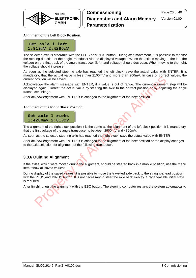
Commissioning Page 20 of 40
Diagnostics and Alarm Memory Version 01.00 MOBILELEKTRONIKGMBH Parameterization
Manual_SLC019146_Part3_V0100.doc 3 Commissioning
Alignment of the Left Block Position:
The selected axle is steerable with the PLUS or MINUS button. During axle movement, it is possible to monitor the rotating direction of the angle transducer via the displayed voltages. When the axle is moving to the left, the voltage on the first track of the angle transducer (left-hand voltage) should decrease. When moving to the right, the voltage should increase. As soon as the selected steering axle has reached the left block, save the actual value with ENTER. It is mandatory, that the actual value is less than 2100mV and more than 200mV. In case of correct values, the current position will be saved. Acknowledge the alarm message with ENTER, if a value is out of range. The current alignment step will be displayed again. Correct the actual value by steering the axle to the correct position or by adjusting the angle transducer linkage. After acknowledgement with ENTER, it is changed to the alignment of the next position. Alignment of the Right Block Position:
The alignment of the right block position it is the same as the alignment of the left block position. It is mandatory that the first voltage of the angle transducer is between 2900mV and 4800mV. As soon as the selected steering axle has reached the right block, save the actual value with ENTER After acknowledgement with ENTER, it is changed to the alignment of the next position or the display changes to the axle selection for alignment of the following transducer.
3.3.6 Quitting Alignment If the axles, which were moved during the alignment, should be steered back in a mobile position, use the menu item “show all saved values”.
During display of the saved values, it is possible to move the travelled axle back to the straight-ahead position with the PLUS and MINUS button. It is not necessary to steer the axle back exactly. Only a feasible initial state is required.
After finishing, quit the alignment with the ESC button. The steering computer restarts the system automatically.
Set axle 1 right1:4280mV 2:819mV
Set axle 1 left1:819mV 2:4280mV
Prope
rty o
f Am
erica
n Airli
nes
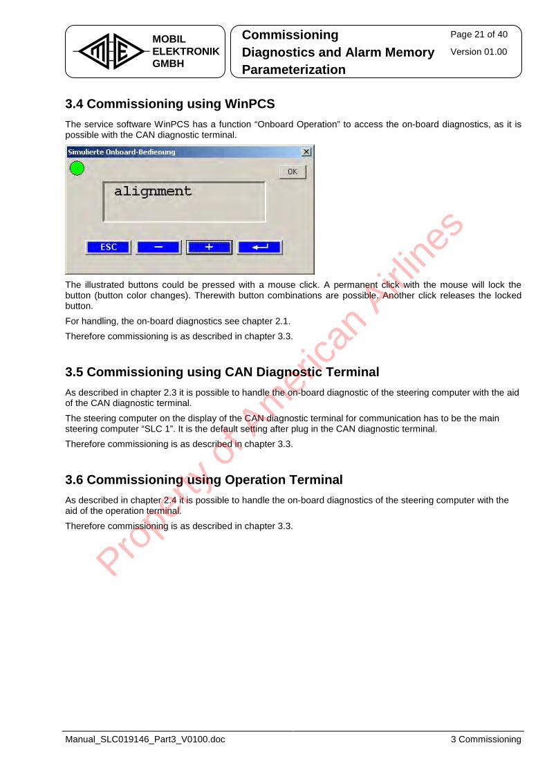
Commissioning Page 21 of 40
Diagnostics and Alarm Memory Version 01.00 MOBILELEKTRONIKGMBH Parameterization
Manual_SLC019146_Part3_V0100.doc 3 Commissioning
3.4 Commissioning using WinPCS The service software WinPCS has a function “Onboard Operation” to access the on-board diagnostics, as it is possible with the CAN diagnostic terminal.
The illustrated buttons could be pressed with a mouse click. A permanent click with the mouse will lock the button (button color changes). Therewith button combinations are possible. Another click releases the locked button.
For handling, the on-board diagnostics see chapter 2.1. Therefore commissioning is as described in chapter 3.3.
3.5 Commissioning using CAN Diagnostic Terminal As described in chapter 2.3 it is possible to handle the on-board diagnostic of the steering computer with the aid of the CAN diagnostic terminal.
The steering computer on the display of the CAN diagnostic terminal for communication has to be the main steering computer “SLC 1”. It is the default setting after plug in the CAN diagnostic terminal. Therefore commissioning is as described in chapter 3.3.
3.6 Commissioning using Operation Terminal As described in chapter 2.4 it is possible to handle the on-board diagnostics of the steering computer with the aid of the operation terminal.
Therefore commissioning is as described in chapter 3.3.
Prope
rty o
f Am
erica
n Airli
nes
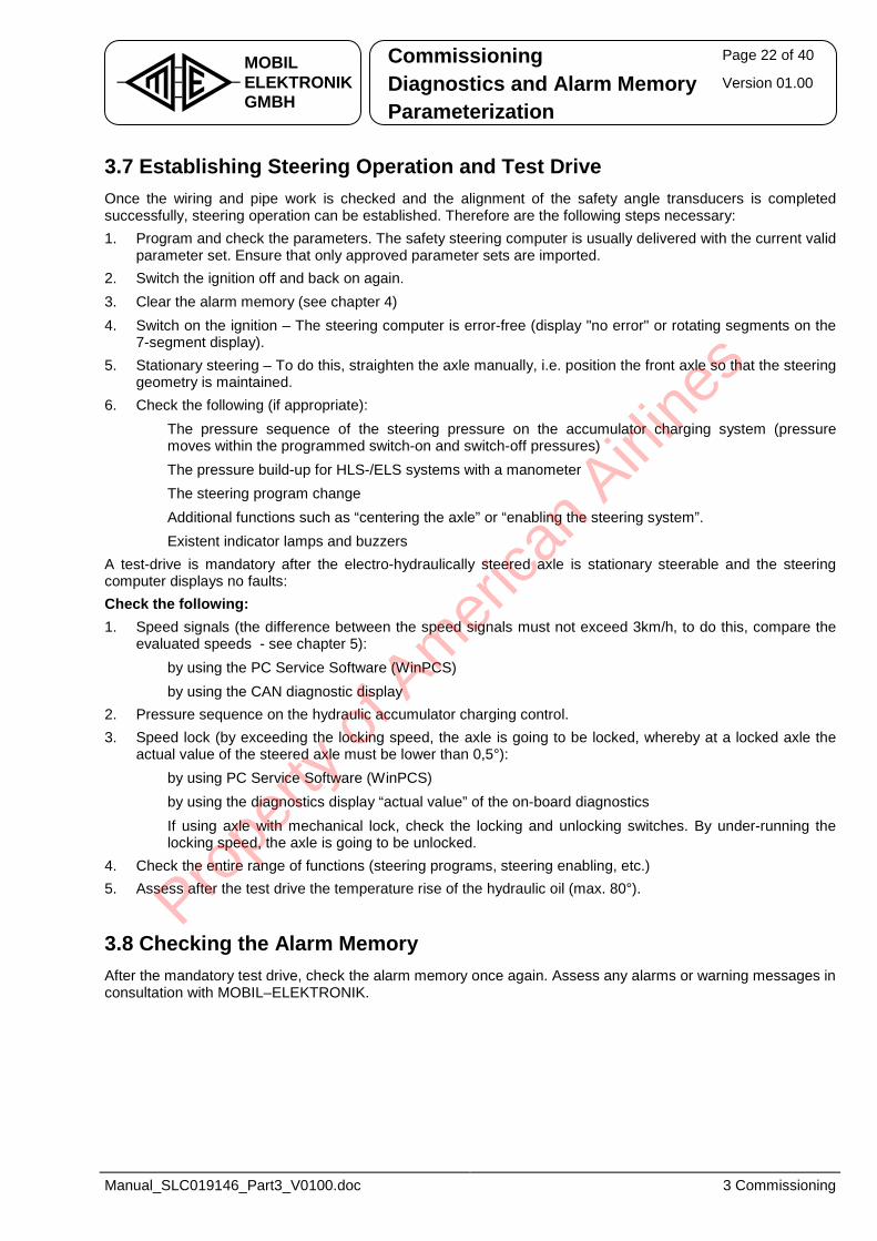
Commissioning Page 22 of 40
Diagnostics and Alarm Memory Version 01.00 MOBILELEKTRONIKGMBH Parameterization
Manual_SLC019146_Part3_V0100.doc 3 Commissioning
3.7 Establishing Steering Operation and Test Drive Once the wiring and pipe work is checked and the alignment of the safety angle transducers is completed successfully, steering operation can be established. Therefore are the following steps necessary: 1. Program and check the parameters. The safety steering computer is usually delivered with the current valid
parameter set. Ensure that only approved parameter sets are imported. 2. Switch the ignition off and back on again. 3. Clear the alarm memory (see chapter 4) 4. Switch on the ignition – The steering computer is error-free (display "no error" or rotating segments on the
7-segment display). 5. Stationary steering – To do this, straighten the axle manually, i.e. position the front axle so that the steering
geometry is maintained. 6. Check the following (if appropriate):
• The pressure sequence of the steering pressure on the accumulator charging system (pressure moves within the programmed switch-on and switch-off pressures)
• The pressure build-up for HLS-/ELS systems with a manometer • The steering program change • Additional functions such as “centering the axle” or “enabling the steering system”. • Existent indicator lamps and buzzers
A test-drive is mandatory after the electro-hydraulically steered axle is stationary steerable and the steering computer displays no faults: Check the following: 1. Speed signals (the difference between the speed signals must not exceed 3km/h, to do this, compare the
evaluated speeds - see chapter 5): • by using the PC Service Software (WinPCS) • by using the CAN diagnostic display
2. Pressure sequence on the hydraulic accumulator charging control. 3. Speed lock (by exceeding the locking speed, the axle is going to be locked, whereby at a locked axle the
actual value of the steered axle must be lower than 0,5°): • by using PC Service Software (WinPCS) • by using the diagnostics display “actual value” of the on-board diagnostics • If using axle with mechanical lock, check the locking and unlocking switches. By under-running the
locking speed, the axle is going to be unlocked. 4. Check the entire range of functions (steering programs, steering enabling, etc.) 5. Assess after the test drive the temperature rise of the hydraulic oil (max. 80°).
3.8 Checking the Alarm Memory After the mandatory test drive, check the alarm memory once again. Assess any alarms or warning messages in consultation with MOBIL–ELEKTRONIK.
Prope
rty o
f Am
erica
n Airli
nes

Commissioning Page 23 of 40
Diagnostics and Alarm Memory Version 01.00 MOBILELEKTRONIKGMBH Parameterization
Manual_SLC019146_Part3_V0100.doc 4 Reading and Clearing the Alarm Memory
4 Reading and Clearing the Alarm Memory The following chapters are describing the several possibilities how to read out and clear the alarm memory. A list of alarms in detail and their description are contained in the part 4 of the system documentation.
4.1 Handling the Alarm Memory using On-Board Diagnostic
4.1.1 Display of Current Alarms at Malfunction The faultless state of the steering system is indicated with “R E A D Y” by the on-board diagnostics. It is changed to the alarm indication at a malfunction or in case of existing information. Active alarms are indicated with an alarm code.
To be able to indicate multiple malfunctions of the steering system, all active alarms are displayed successively with their alarm code. Approximately every 2,5s changes the display. After indication of the last active alarm, the first alarm indication starts.
4.1.2 Reading Out the Alarm Memory Firstly, access the diagnostics menu of the steering computer based on the initial state. Therefore press the ENTER button for at least 1 second. Afterwards it is possible to select the menu item “alarm memory” with the PLUS or MINUS button and to activate it with ENTER. The display changes to the first saved alarm. With the ESC button, it is possible to quit the alarm memory menu at any time. Indicate the alarms successively by pressing the PLUS or MINUS button. At the end of the alarm memory (alarm no. 32) an automatic rebound to the start is done (alarm no. 1). With the ENTER button are further information to the current indicated alarm available. Successively indicated are the alarm code, moment of the first appearance, moment of the last appearance, the occurrence and the DTC code:
Alarm code: location – type – priority → alarm allocation according to the steering computer
Moment of the first alarm appearance
Moment of the last alarm appearance
Alarm occurrence
J1939 trouble code: SPN – FMI – FP → alarm allocation according to the axle numbers
As soon as an alarm code “255 – 255 – 255” appears, no further alarms are saved in the alarm memory. The alarm before is the last one. With a totally cleared (empty) alarm memory there are only entries with 255 contained.
trouble code:10425 – 09 - 03
frequency:4
time last entry08.01. 08:02:36
time first entry 06.01. 06:51:14
alarm index: 1code: 180 006 00
Prope
rty o
f Am
erica
n Airli
nes

Commissioning Page 24 of 40
Diagnostics and Alarm Memory Version 01.00 MOBILELEKTRONIKGMBH Parameterization
Manual_SLC019146_Part3_V0100.doc 4 Reading and Clearing the Alarm Memory
4.1.3 Clearing the Alarm Memory Clearing the alarm memory is possible at each indication state of the alarm memory menu.
Press the PLUS button for at least 3 seconds.
Access is only permitted to authorized persons. The access is not initialized yet, if this display occurs. Please have a look at the menu “access code” (see chapter 2.1).
At this stage it is still possible quit without clearing the alarm memory. Therefore use the ESC button. The display changes to the alarm memory indication again.
Press the ENTER button to start the clearing sequence.
The second line indicates a progress bar.
After clearing, all entries are set to 255. The display changes automatically to the first entry.
Quit the menu item “alarm memory” with the ESC button afterwards. Restart the steering computer after clearing the alarm memory (ignition off / on).
alarm memoryaccess denied
alarm index: 1code: 180 006 00
clearing !--------
alarm memoryclear memory ?
Prope
rty o
f Am
erica
n Airli
nes
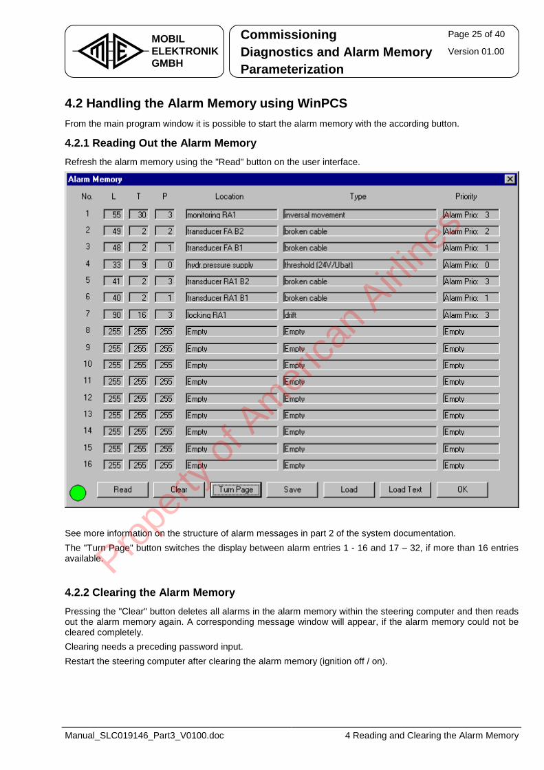
Commissioning Page 25 of 40
Diagnostics and Alarm Memory Version 01.00 MOBILELEKTRONIKGMBH Parameterization
Manual_SLC019146_Part3_V0100.doc 4 Reading and Clearing the Alarm Memory
4.2 Handling the Alarm Memory using WinPCS From the main program window it is possible to start the alarm memory with the according button.
4.2.1 Reading Out the Alarm Memory Refresh the alarm memory using the "Read" button on the user interface.
See more information on the structure of alarm messages in part 2 of the system documentation. The "Turn Page" button switches the display between alarm entries 1 - 16 and 17 – 32, if more than 16 entries available.
4.2.2 Clearing the Alarm Memory Pressing the "Clear" button deletes all alarms in the alarm memory within the steering computer and then reads out the alarm memory again. A corresponding message window will appear, if the alarm memory could not be cleared completely. Clearing needs a preceding password input. Restart the steering computer after clearing the alarm memory (ignition off / on).
Prope
rty o
f Am
erica
n Airli
nes

Commissioning Page 26 of 40
Diagnostics and Alarm Memory Version 01.00 MOBILELEKTRONIKGMBH Parameterization
Manual_SLC019146_Part3_V0100.doc 4 Reading and Clearing the Alarm Memory
4.3 Handling the Alarm Memory using CAN Diagnostic Terminal As described in chapter 2.3 it is possible to handle the on-board diagnostics of the steering computer with the aid of the CAN diagnostic terminal. Therefore, handling is as described in chapter 4.1.
4.4 Handling the Alarm Memory using Operation Terminal As described in chapter 2.4 it is possible to handle the on-board diagnostics of the steering computer with the aid of the operating terminal. Therefore, handling is as described in chapter 4.1.
Prope
rty o
f Am
erica
n Airli
nes
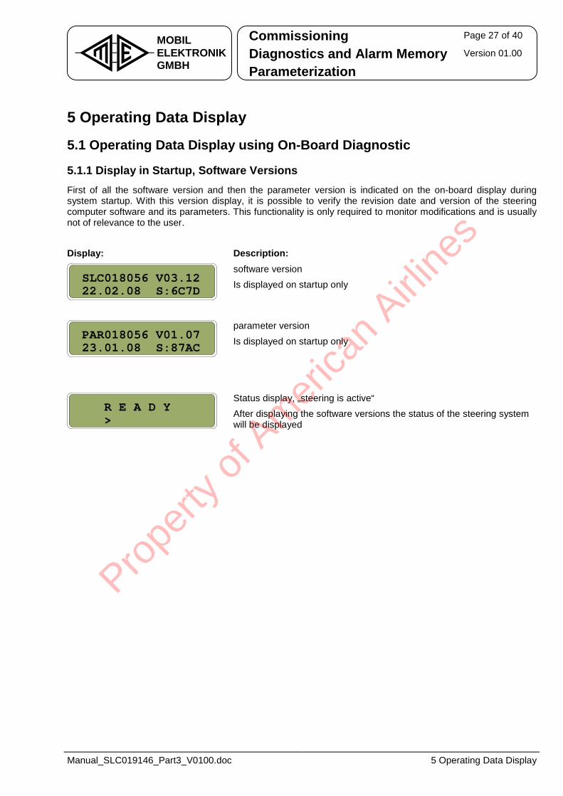
Commissioning Page 27 of 40
Diagnostics and Alarm Memory Version 01.00 MOBILELEKTRONIKGMBH Parameterization
Manual_SLC019146_Part3_V0100.doc 5 Operating Data Display
5 Operating Data Display
5.1 Operating Data Display using On-Board Diagnostic
5.1.1 Display in Startup, Software Versions First of all the software version and then the parameter version is indicated on the on-board display during system startup. With this version display, it is possible to verify the revision date and version of the steering computer software and its parameters. This functionality is only required to monitor modifications and is usually not of relevance to the user. Display: Description:
software version Is displayed on startup only
parameter version
Is displayed on startup only
Status display, „steering is active“ After displaying the software versions the status of the steering system will be displayed
R E A D Y>
PAR018056 V01.0723.01.08 S:87AC
SLC018056 V03.1222.02.08 S:6C7D
Prope
rty o
f Am
erica
n Airli
nes
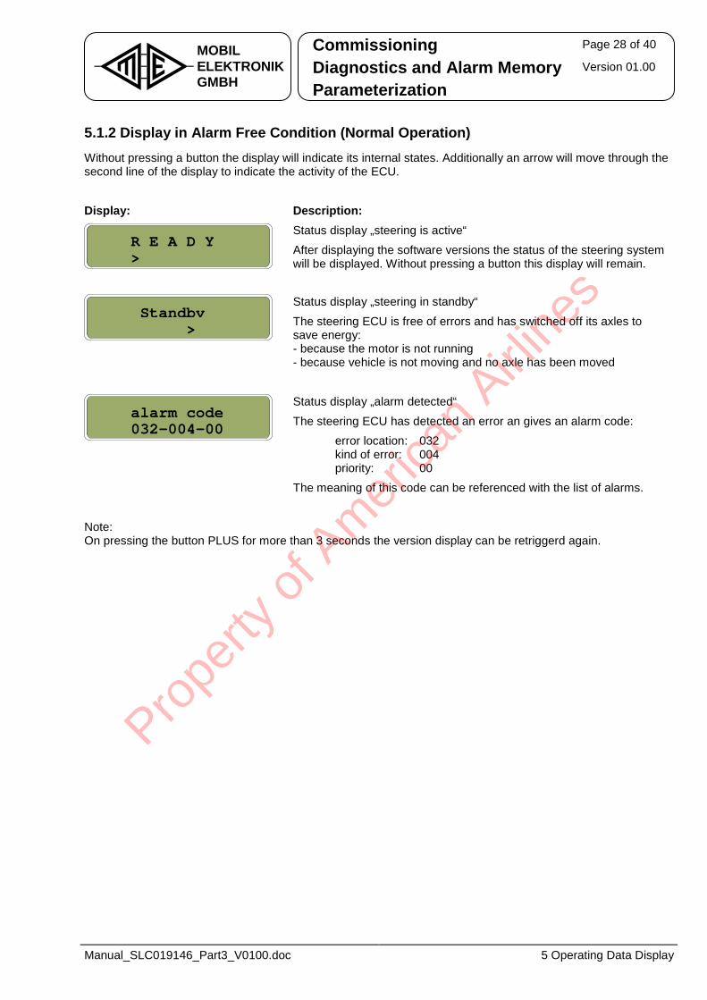
Commissioning Page 28 of 40
Diagnostics and Alarm Memory Version 01.00 MOBILELEKTRONIKGMBH Parameterization
Manual_SLC019146_Part3_V0100.doc 5 Operating Data Display
5.1.2 Display in Alarm Free Condition (Normal Operation) Without pressing a button the display will indicate its internal states. Additionally an arrow will move through the second line of the display to indicate the activity of the ECU. Display: Description:
Status display „steering is active“
After displaying the software versions the status of the steering system will be displayed. Without pressing a button this display will remain.
Status display „steering in standby“
The steering ECU is free of errors and has switched off its axles to save energy: - because the motor is not running - because vehicle is not moving and no axle has been moved
Status display „alarm detected“
The steering ECU has detected an error an gives an alarm code: error location: 032 kind of error: 004 priority: 00 The meaning of this code can be referenced with the list of alarms.
Note: On pressing the button PLUS for more than 3 seconds the version display can be retriggerd again.
alarm code032-004-00
Standby>
R E A D Y>
Prope
rty o
f Am
erica
n Airli
nes
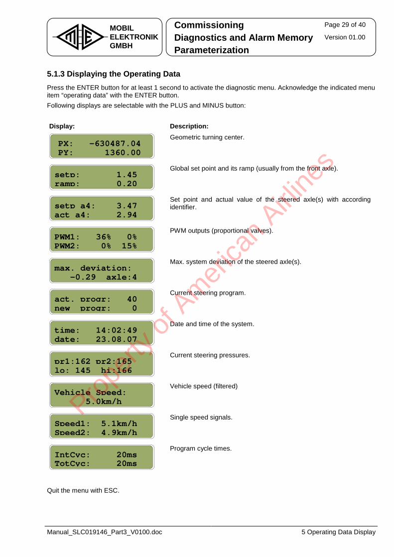
Commissioning Page 29 of 40
Diagnostics and Alarm Memory Version 01.00 MOBILELEKTRONIKGMBH Parameterization
Manual_SLC019146_Part3_V0100.doc 5 Operating Data Display
5.1.3 Displaying the Operating Data Press the ENTER button for at least 1 second to activate the diagnostic menu. Acknowledge the indicated menu item “operating data” with the ENTER button. Following displays are selectable with the PLUS and MINUS button: Display: Description:
Geometric turning center.
Global set point and its ramp (usually from the front axle).
Set point and actual value of the steered axle(s) with according identifier.
PWM outputs (proportional valves).
Max. system deviation of the steered axle(s).
Current steering program.
Date and time of the system.
Current steering pressures.
Vehicle speed (filtered)
Single speed signals.
Program cycle times.
Quit the menu with ESC.
Speed1: 5.1km/hSpeed2: 4.9km/h
Vehicle Speed:5.0km/h
pr1:162 pr2:165lo: 145 hi:166
time: 14:02:49date: 23.08.07
act. progr: 40new progr: 0
max. deviation:-0.29 axle:4
PWM1: 36% 0%PWM2: 0% 15%
setp: 1.45ramp: 0.20
PX: -630487.04PY: 1360.00
IntCyc: 20msTotCyc: 20ms
setp a4: 3.47act a4: 2.94
Prope
rty o
f Am
erica
n Airli
nes
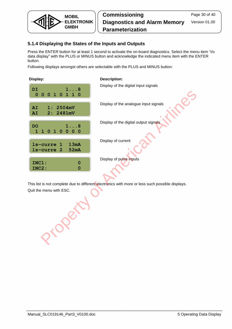
Commissioning Page 30 of 40
Diagnostics and Alarm Memory Version 01.00 MOBILELEKTRONIKGMBH Parameterization
Manual_SLC019146_Part3_V0100.doc 5 Operating Data Display
5.1.4 Displaying the States of the Inputs and Outputs Press the ENTER button for at least 1 second to activate the on-board diagnostics. Select the menu item “i/o data display” with the PLUS or MINUS button and acknowledge the indicated menu item with the ENTER button. Following displays amongst others are selectable with the PLUS and MINUS button: Display: Description:
Display of the digital input signals
Display of the analogue input signals
Display of the digital output signals
Display of current
Display of pulse inputs
This list is not complete due to different electronics with more or less such possible displays. Quit the menu with ESC.
INC1: 0INC2: 0
ls-curre 1 13mAls-curre 2 52mA
AI 1: 2504mVAI 2: 2481mV
DI 1...80 0 0 1 0 1 1 0
DO 1...81 1 0 1 0 0 0 0
Prope
rty o
f Am
erica
n Airli
nes
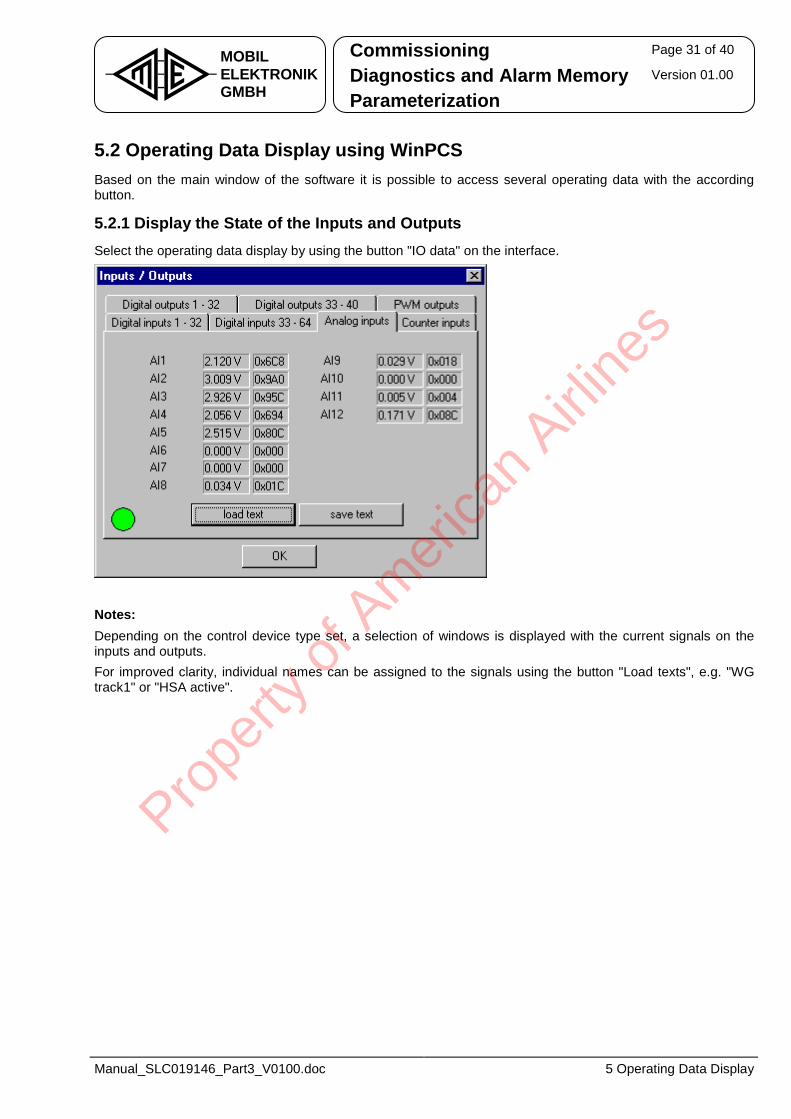
Commissioning Page 31 of 40
Diagnostics and Alarm Memory Version 01.00 MOBILELEKTRONIKGMBH Parameterization
Manual_SLC019146_Part3_V0100.doc 5 Operating Data Display
5.2 Operating Data Display using WinPCS Based on the main window of the software it is possible to access several operating data with the according button.
5.2.1 Display the State of the Inputs and Outputs Select the operating data display by using the button "IO data" on the interface.
Notes: Depending on the control device type set, a selection of windows is displayed with the current signals on the inputs and outputs. For improved clarity, individual names can be assigned to the signals using the button "Load texts", e.g. "WG track1" or "HSA active".
Prope
rty o
f Am
erica
n Airli
nes
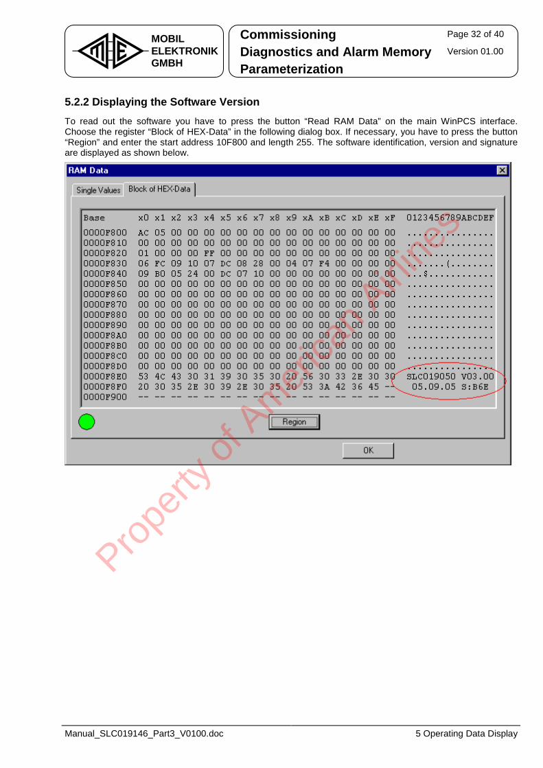
Commissioning Page 32 of 40
Diagnostics and Alarm Memory Version 01.00 MOBILELEKTRONIKGMBH Parameterization
Manual_SLC019146_Part3_V0100.doc 5 Operating Data Display
5.2.2 Displaying the Software Version To read out the software you have to press the button “Read RAM Data” on the main WinPCS interface. Choose the register “Block of HEX-Data” in the following dialog box. If necessary, you have to press the button “Region” and enter the start address 10F800 and length 255. The software identification, version and signature are displayed as shown below.
Prope
rty o
f Am
erica
n Airli
nes
Commissioning Page 33 of 40
Diagnostics and Alarm Memory Version 01.00 MOBILELEKTRONIKGMBH Parameterization
Manual_SLC019146_Part3_V0100.doc 5 Operating Data Display
5.3 Operating Data Display using CAN Diagnostic Terminal As described in chapter 2.3 it is possible to handle the on-board diagnostics of the steering computer with the aid of the CAN diagnostic terminal. Therefore, operating data display is as described in chapter 5.1.
5.4 Operating Data Display using Operating Terminal As described in chapter 2.4 it is possible to handle the on-board diagnostics of the steering computer with the aid of the operating terminal. Therefore, operating data display is as described in chapter 5.1.
To leave the diagnostic mode with indication of the steering computer press the buttons 1 and 2 (lower bank of buttons) simultaneously. Afterwards the position of the rear axle is displayed with a bar graph again.
Prope
rty o
f Am
erica
n Airli
nes
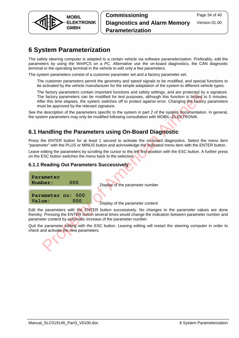
Commissioning Page 34 of 40
Diagnostics and Alarm Memory Version 01.00 MOBILELEKTRONIKGMBH Parameterization
Manual_SLC019146_Part3_V0100.doc 6 System Parameterization
6 System Parameterization The safety steering computer is adapted to a certain vehicle via software parameterization. Preferably, edit the parameters by using the WinPCS on a PC. Alternative use the on-board diagnostics, the CAN diagnostic terminal or the operating terminal in the vehicle to edit only a few parameters. The system parameters consist of a customer parameter set and a factory parameter set. • The customer parameters permit the geometry and speed signals to be modified, and special functions to
be activated by the vehicle manufacturer for the simple adaptation of the system to different vehicle types. • The factory parameters contain important functions and safety settings, and are protected by a signature.
The factory parameters can be modified for test purposes, although this function is limited to 5 minutes. After this time elapses, the system switches off to protect against error. Changing the factory parameters must be approved by the relevant signature.
See the description of the parameters specific to the system in part 2 of the system documentation. In general, the system parameters may only be modified following consultation with MOBIL–ELEKTRONIK.
6.1 Handling the Parameters using On-Board Diagnostic Press the ENTER button for at least 1 second to activate the on-board diagnostics. Select the menu item “parameter” with the PLUS or MINUS button and acknowledge the indicated menu item with the ENTER button. Leave editing the parameters by scrolling the cursor to the left first position with the ESC button. A further press on the ESC button switches the menu back to the selection.
6.1.1 Reading Out Parameters Successively
Display of the parameter number
Display of the parameter content Edit the parameters with the ENTER button successively. No changes to the parameter values are done thereby. Pressing the ENTER button several times would change the indication between parameter number and parameter content by automatic increase of the parameter number.
Quit the parameter editing with the ESC button. Leaving editing will restart the steering computer in order to check and activate the new parameters.
ParameterNumber: 000_
Parameter no: 000Value: 000_
Prope
rty o
f Am
erica
n Airli
nes
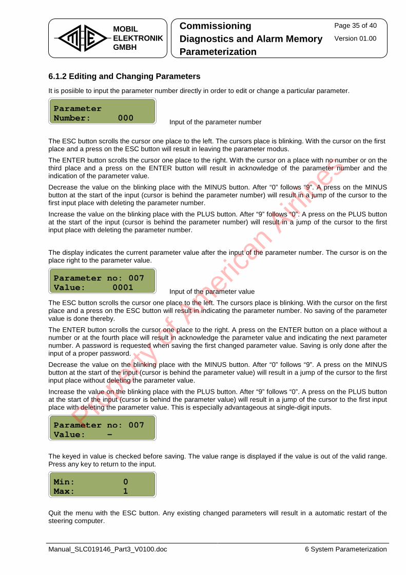
Commissioning Page 35 of 40
Diagnostics and Alarm Memory Version 01.00 MOBILELEKTRONIKGMBH Parameterization
Manual_SLC019146_Part3_V0100.doc 6 System Parameterization
6.1.2 Editing and Changing Parameters It is posiible to input the parameter number directly in order to edit or change a particular parameter.
Input of the parameter number
The ESC button scrolls the cursor one place to the left. The cursors place is blinking. With the cursor on the first place and a press on the ESC button will result in leaving the parameter modus.
The ENTER button scrolls the cursor one place to the right. With the cursor on a place with no number or on the third place and a press on the ENTER button will result in acknowledge of the parameter number and the indication of the parameter value.
Decrease the value on the blinking place with the MINUS button. After “0” follows “9”. A press on the MINUS button at the start of the input (cursor is behind the parameter number) will result in a jump of the cursor to the first input place with deleting the parameter number.
Increase the value on the blinking place with the PLUS button. After “9” follows “0”. A press on the PLUS button at the start of the input (cursor is behind the parameter number) will result in a jump of the cursor to the first input place with deleting the parameter number.
The display indicates the current parameter value after the input of the parameter number. The cursor is on the place right to the parameter value.
Input of the parameter value The ESC button scrolls the cursor one place to the left. The cursors place is blinking. With the cursor on the first place and a press on the ESC button will result in indicating the parameter number. No saving of the parameter value is done thereby. The ENTER button scrolls the cursor one place to the right. A press on the ENTER button on a place without a number or at the fourth place will result in acknowledge the parameter value and indicating the next parameter number. A password is requested when saving the first changed parameter value. Saving is only done after the input of a proper password. Decrease the value on the blinking place with the MINUS button. After “0” follows “9”. A press on the MINUS button at the start of the input (cursor is behind the parameter value) will result in a jump of the cursor to the first input place without deleting the parameter value.
Increase the value on the blinking place with the PLUS button. After “9” follows “0”. A press on the PLUS button at the start of the input (cursor is behind the parameter value) will result in a jump of the cursor to the first input place with deleting the parameter value. This is especially advantageous at single-digit inputs.
The keyed in value is checked before saving. The value range is displayed if the value is out of the valid range. Press any key to return to the input.
Quit the menu with the ESC button. Any existing changed parameters will result in a automatic restart of the steering computer.
Min: 0Max: 1
Parameter no: 007Value: -
Parameter no: 007Value: 0001__
ParameterNumber: 000_
Prope
rty o
f Am
erica
n Airli
nes
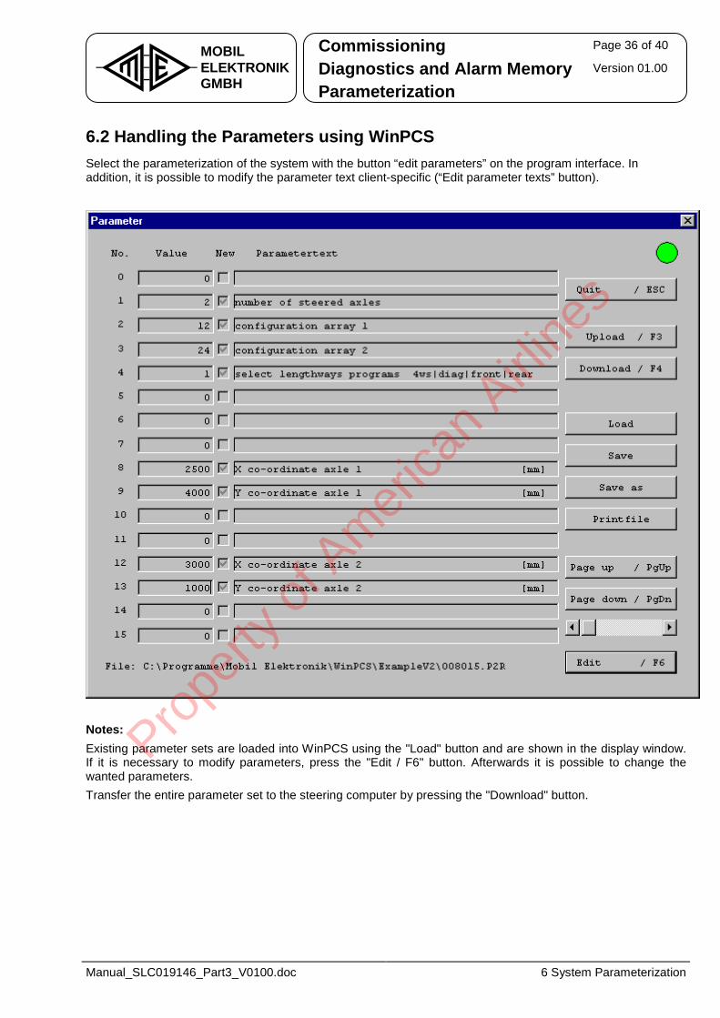
Commissioning Page 36 of 40
Diagnostics and Alarm Memory Version 01.00 MOBILELEKTRONIKGMBH Parameterization
Manual_SLC019146_Part3_V0100.doc 6 System Parameterization
6.2 Handling the Parameters using WinPCS Select the parameterization of the system with the button “edit parameters” on the program interface. In addition, it is possible to modify the parameter text client-specific (“Edit parameter texts” button).
Notes: Existing parameter sets are loaded into WinPCS using the "Load" button and are shown in the display window. If it is necessary to modify parameters, press the "Edit / F6" button. Afterwards it is possible to change the wanted parameters. Transfer the entire parameter set to the steering computer by pressing the "Download" button.
Prope
rty o
f Am
erica
n Airli
nes
Commissioning Page 37 of 40
Diagnostics and Alarm Memory Version 01.00 MOBILELEKTRONIKGMBH Parameterization
Manual_SLC019146_Part3_V0100.doc 6 System Parameterization
6.3 Handling the Parameters using CAN Diagnostic Terminal As described in chapter 2.3 it is possible to handle the on-board diagnostics of the steering computer with the aid of the CAN diagnostic terminal. Therefore, handling the parameters is as described in chapter 6.1.
6.4 Handling the Parameters using Operation Terminal As described in chapter 2.4 it is possible to handle the on-board diagnostics of the steering computer with the aid of the operating terminal. Therefore, handling the parameters is as described in chapter 6.1. To leave the diagnostic mode with indication of the steering computer press the buttons 1 and 2 (lower bank of buttons) simultaneously. Afterwards the position of the rear axle is displayed with a bar graph again.
Prope
rty o
f Am
erica
n Airli
nes
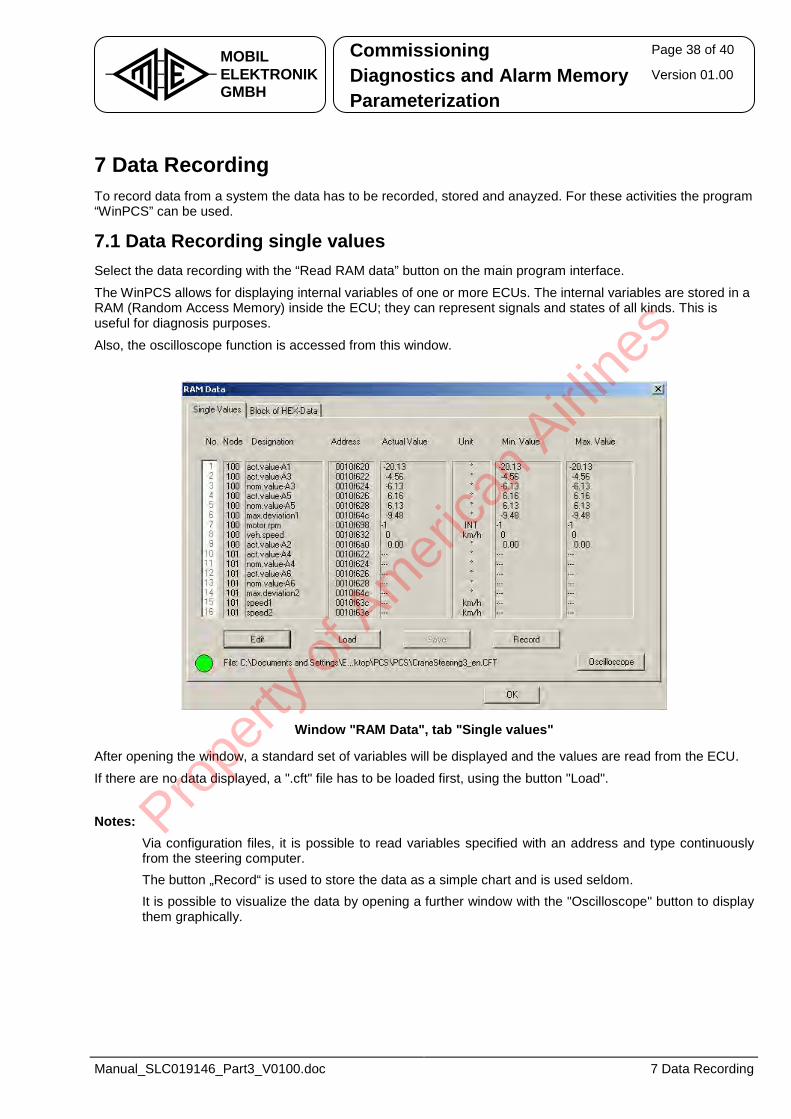
Commissioning Page 38 of 40
Diagnostics and Alarm Memory Version 01.00 MOBILELEKTRONIKGMBH Parameterization
Manual_SLC019146_Part3_V0100.doc 7 Data Recording
7 Data Recording To record data from a system the data has to be recorded, stored and anayzed. For these activities the program “WinPCS” can be used.
7.1 Data Recording single values Select the data recording with the “Read RAM data” button on the main program interface.
The WinPCS allows for displaying internal variables of one or more ECUs. The internal variables are stored in a RAM (Random Access Memory) inside the ECU; they can represent signals and states of all kinds. This is useful for diagnosis purposes.
Also, the oscilloscope function is accessed from this window.
Window "RAM Data", tab "Single values"
After opening the window, a standard set of variables will be displayed and the values are read from the ECU.
If there are no data displayed, a ".cft" file has to be loaded first, using the button "Load". Notes:
• Via configuration files, it is possible to read variables specified with an address and type continuously from the steering computer.
• The button „Record“ is used to store the data as a simple chart and is used seldom. • It is possible to visualize the data by opening a further window with the "Oscilloscope" button to display
them graphically.
Prope
rty o
f Am
erica
n Airli
nes
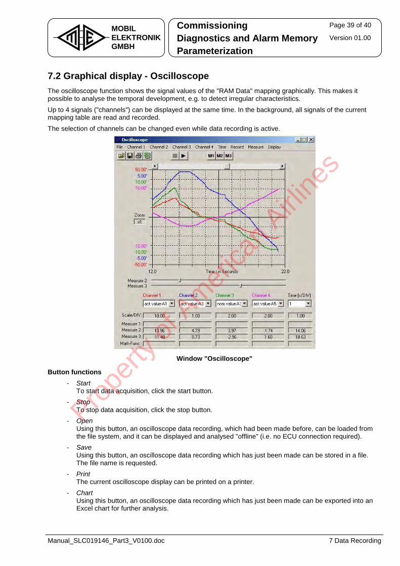
Commissioning Page 39 of 40
Diagnostics and Alarm Memory Version 01.00 MOBILELEKTRONIKGMBH Parameterization
Manual_SLC019146_Part3_V0100.doc 7 Data Recording
7.2 Graphical display - Oscilloscope The oscilloscope function shows the signal values of the "RAM Data" mapping graphically. This makes it possible to analyse the temporal development, e.g. to detect irregular characteristics.
Up to 4 signals ("channels") can be displayed at the same time. In the background, all signals of the current mapping table are read and recorded.
The selection of channels can be changed even while data recording is active.
Window "Oscilloscope"
Button functions - Start
To start data acquisition, click the start button. - Stop
To stop data acquisition, click the stop button. - Open
Using this button, an oscilloscope data recording, which had been made before, can be loaded from the file system, and it can be displayed and analysed "offline" (i.e. no ECU connection required).
- Save Using this button, an oscilloscope data recording which has just been made can be stored in a file. The file name is requested.
- Print The current oscilloscope display can be printed on a printer.
- Chart Using this button, an oscilloscope data recording which has just been made can be exported into an Excel chart for further analysis.
Prope
rty o
f Am
erica
n Airli
nes
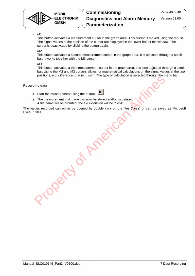
Commissioning Page 40 of 40
Diagnostics and Alarm Memory Version 01.00 MOBILELEKTRONIKGMBH Parameterization
Manual_SLC019146_Part3_V0100.doc 7 Data Recording
- M1 This button activates a measurement cursor in the graph area. This cursor is moved using the mouse. The signal values at the position of the cursor are displayed in the lower half of the window. The cursor is deactivated by clicking the button again.
- M2 This button activates a second measurement cursor in the graph area. It is adjusted through a scroll bar. It works together with the M3 cursor.
- M3 This button activates a third measurement cursor in the graph area. It is also adjusted through a scroll bar. Using the M2 and M3 cursors allows for mathematical calculations on the signal values at the two positions, e.g. difference, gradient, sum. The type of calculation is selected through the menu bar.
Recording data
1. Start the measurement using the button .2. The measurement just made can now be stored and/or visualised.
A file name will be promted, the file extension will be “*.osz” The values recorded can either be opened by double click on the files (*.osz) or can be saved as Microsoft Excel™ files.
Prope
rty o
f Am
erica
n Airli
nes
Bössingerstraße 33 D-74243 Langenbeutingen � +49 (0) 7946 / 9194 - 0 FAX +49 (0) 7946 / 9194 - 130 http://www.mobil-elektronik.com
System Documentation - Part 4 Alarm List ME Alarm Codes
Electro-Hydraulic Auxiliary Steering System for Rear Axles
Type: SLC 019 146
Prope
rty o
f Am
erica
n Airli
nes
Alarm List Page 2 of 49
ME Alarm Codes Version 01.02
Manual_SLC019146_Part4_V0102.doc 0 History
Table of Contents History ............................................................................................................... 3
1 General ........................................................................................................... 4
1.1 Safety Notes................................................................................................................... 4
2 Alarm list......................................................................................................... 5
2.1 System Alarms (L-Errors) ............................................................................................. 6
2.1 System Alarms (L-Errors Failop) ............................................................................... 40
2.2 Control Unit Alarms (U-Errors)................................................................................... 44
Prope
rty o
f Am
erica
n Airli
nes
Alarm List Page 3 of 49
ME Alarm Codes Version 01.02
Manual_SLC019146_Part4_V0102.doc 0 History
History File Manual_SLC019146_Part4_V0101.doc
01.00 2011-05-09 TH new document based on “Manual_EHLA-Multi_Std_Part 4_V0204.doc”
01.01 2011-08-09 TH added ETC1 fault codes
01.02 2012-02-22 TH added new fault codes for dual cab variant
Version
Subject to technical modifications.
Prope
rty o
f Am
erica
n Airli
nes
Alarm List Page 4 of 49
ME Alarm Codes Version 01.02
Manual_SLC019146_Part4_V0102.doc 1 General
1 General The system documentation EHLA (electro-hydraulic steering system) comprises four parts:
1. System description, installation and maintenance 2. Project specific documentation
3. Commissioning and diagnostics 4. Alarm list
This third part on hand contains the error lists. For defined characters and abbreviations, see part 1 of the system documentation.
1.1 Safety Notes
Safety note: Please observe absolutely the safety notes from part 1 of the system documentation.
Prope
rty o
f Am
erica
n Airli
nes
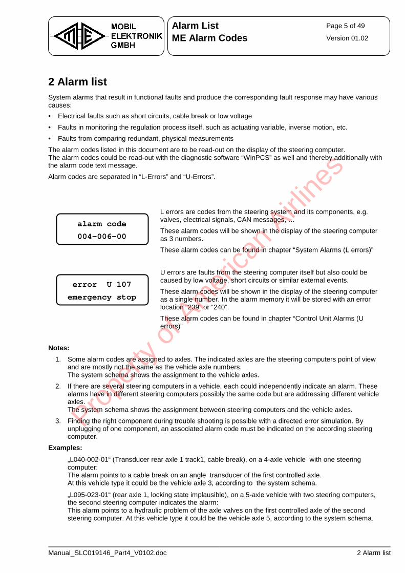
Alarm List Page 5 of 49
ME Alarm Codes Version 01.02
Manual_SLC019146_Part4_V0102.doc 2 Alarm list
2 Alarm list System alarms that result in functional faults and produce the corresponding fault response may have various causes: • Electrical faults such as short circuits, cable break or low voltage
• Faults in monitoring the regulation process itself, such as actuating variable, inverse motion, etc. • Faults from comparing redundant, physical measurements
The alarm codes listed in this document are to be read-out on the display of the steering computer. The alarm codes could be read-out with the diagnostic software “WinPCS” as well and thereby additionally with the alarm code text message.
Alarm codes are separated in “L-Errors” and “U-Errors”.
L errors are codes from the steering system and its components, e.g. valves, electrical signals, CAN messages, …
These alarm codes will be shown in the display of the steering computer as 3 numbers. These alarm codes can be found in chapter “System Alarms (L errors)”
U errors are faults from the steering computer itself but also could be caused by low voltage, short circuits or similar external events.
These alarm codes will be shown in the display of the steering computer as a single number. In the alarm memory it will be stored with an error location “239” or “240”.
These alarm codes can be found in chapter “Control Unit Alarms (U errors)”
Notes:
1. Some alarm codes are assigned to axles. The indicated axles are the steering computers point of view and are mostly not the same as the vehicle axle numbers. The system schema shows the assignment to the vehicle axles.
2. If there are several steering computers in a vehicle, each could independently indicate an alarm. These alarms have in different steering computers possibly the same code but are addressing different vehicle axles. The system schema shows the assignment between steering computers and the vehicle axles.
3. Finding the right component during trouble shooting is possible with a directed error simulation. By unplugging of one component, an associated alarm code must be indicated on the according steering computer.
Examples:
• „L040-002-01“ (Transducer rear axle 1 track1, cable break), on a 4-axle vehicle with one steering computer: The alarm points to a cable break on an angle transducer of the first controlled axle. At this vehicle type it could be the vehicle axle 3, according to the system schema.
• „L095-023-01“ (rear axle 1, locking state implausible), on a 5-axle vehicle with two steering computers, the second steering computer indicates the alarm: This alarm points to a hydraulic problem of the axle valves on the first controlled axle of the second steering computer. At this vehicle type it could be the vehicle axle 5, according to the system schema.
error U 107 emergency stop
alarm code 004-006-00
Prope
rty o
f Am
erica
n Airli
nes
Alarm List Page 6 of 49
ME Alarm Codes Version 01.02
Manual_SLC019146_Part4_V0102.doc 2 Alarm list
2.1 System Alarms (L-Errors) Alarms with causes to be found in peripheral devices, e.g. errors in the wiring, failure of sensors or hydraulic problems are known as L-Errors.
To simplify the process of determining the causes of errors, alarm codes are divided into location, type and priority. An alarm is denoted by the alarm location and alarm type: • Alarm location : E.g. Angle transducer track 1 of rear axle 1, pressure sensor, ...
• Alarm type : E.g. Cable break, maximum value exceeded, ... The priority determines the reaction of the steering system to an alarm: • Priority 0: Warning, the steering characteristics are not affected.
• Priority 1: Move the axle to the next straight position. • Priority 2: Automatic steer to the straight position.
• Priority 3: Safety-based shut-down to a safe status
The underlying safety strategy in place for this is explained in part 2 of the system documentation.
Structure of the alarm table:
Alarm code Description
aaa - bbb – pp Alarm location aaa Alarm type bbb aaa - ccc – pp Alarm location aaa Alarm type ccc
Explanations, notes Alarm type bbb Description Alarm type ccc Description
Prope
rty o
f Am
erica
n Airli
nes
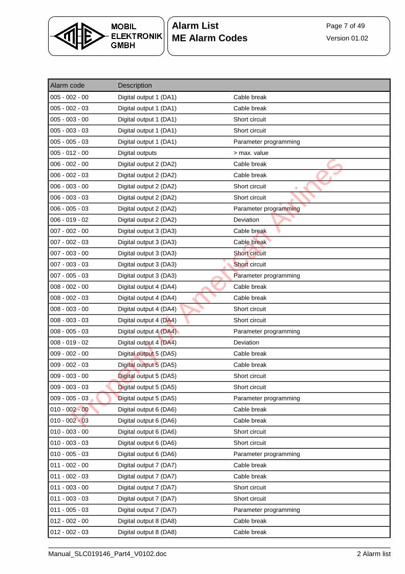
Alarm List Page 7 of 49
ME Alarm Codes Version 01.02
Manual_SLC019146_Part4_V0102.doc 2 Alarm list
Alarm code Description
005 - 002 - 00 Digital output 1 (DA1) Cable break
005 - 002 - 03 Digital output 1 (DA1) Cable break
005 - 003 - 00 Digital output 1 (DA1) Short circuit
005 - 003 - 03 Digital output 1 (DA1) Short circuit
005 - 005 - 03 Digital output 1 (DA1) Parameter programming
005 - 012 - 00 Digital outputs > max. value
006 - 002 - 00 Digital output 2 (DA2) Cable break
006 - 002 - 03 Digital output 2 (DA2) Cable break
006 - 003 - 00 Digital output 2 (DA2) Short circuit
006 - 003 - 03 Digital output 2 (DA2) Short circuit
006 - 005 - 03 Digital output 2 (DA2) Parameter programming
006 - 019 - 02 Digital output 2 (DA2) Deviation
007 - 002 - 00 Digital output 3 (DA3) Cable break
007 - 002 - 03 Digital output 3 (DA3) Cable break
007 - 003 - 00 Digital output 3 (DA3) Short circuit
007 - 003 - 03 Digital output 3 (DA3) Short circuit
007 - 005 - 03 Digital output 3 (DA3) Parameter programming
008 - 002 - 00 Digital output 4 (DA4) Cable break
008 - 002 - 03 Digital output 4 (DA4) Cable break
008 - 003 - 00 Digital output 4 (DA4) Short circuit
008 - 003 - 03 Digital output 4 (DA4) Short circuit
008 - 005 - 03 Digital output 4 (DA4) Parameter programming
008 - 019 - 02 Digital output 4 (DA4) Deviation
009 - 002 - 00 Digital output 5 (DA5) Cable break
009 - 002 - 03 Digital output 5 (DA5) Cable break
009 - 003 - 00 Digital output 5 (DA5) Short circuit
009 - 003 - 03 Digital output 5 (DA5) Short circuit
009 - 005 - 03 Digital output 5 (DA5) Parameter programming
010 - 002 - 00 Digital output 6 (DA6) Cable break
010 - 002 - 03 Digital output 6 (DA6) Cable break
010 - 003 - 00 Digital output 6 (DA6) Short circuit
010 - 003 - 03 Digital output 6 (DA6) Short circuit
010 - 005 - 03 Digital output 6 (DA6) Parameter programming
011 - 002 - 00 Digital output 7 (DA7) Cable break
011 - 002 - 03 Digital output 7 (DA7) Cable break
011 - 003 - 00 Digital output 7 (DA7) Short circuit
011 - 003 - 03 Digital output 7 (DA7) Short circuit
011 - 005 - 03 Digital output 7 (DA7) Parameter programming
012 - 002 - 00 Digital output 8 (DA8) Cable break
012 - 002 - 03 Digital output 8 (DA8) Cable break
Prope
rty o
f Am
erica
n Airli
nes
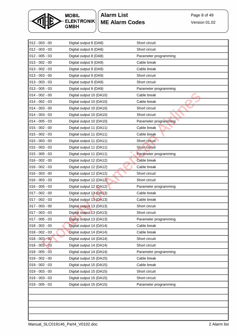
Alarm List Page 8 of 49
ME Alarm Codes Version 01.02
Manual_SLC019146_Part4_V0102.doc 2 Alarm list
012 - 003 - 00 Digital output 8 (DA8) Short circuit
012 - 003 - 03 Digital output 8 (DA8) Short circuit
012 - 005 - 03 Digital output 8 (DA8) Parameter programming
013 - 002 - 00 Digital output 9 (DA9) Cable break
013 - 002 - 03 Digital output 9 (DA9) Cable break
013 - 003 - 00 Digital output 9 (DA9) Short circuit
013 - 003 - 03 Digital output 9 (DA9) Short circuit
013 - 005 - 03 Digital output 9 (DA9) Parameter programming
014 - 002 - 00 Digital output 10 (DA10) Cable break
014 - 002 - 03 Digital output 10 (DA10) Cable break
014 - 003 - 00 Digital output 10 (DA10) Short circuit
014 - 003 - 03 Digital output 10 (DA10) Short circuit
014 - 005 - 03 Digital output 10 (DA10) Parameter programming
015 - 002 - 00 Digital output 11 (DA11) Cable break
015 - 002 - 03 Digital output 11 (DA11) Cable break
015 - 003 - 00 Digital output 11 (DA11) Short circuit
015 - 003 - 03 Digital output 11 (DA11) Short circuit
015 - 005 - 03 Digital output 11 (DA11) Parameter programming
016 - 002 - 00 Digital output 12 (DA12) Cable break
016 - 002 - 03 Digital output 12 (DA12) Cable break
016 - 003 - 00 Digital output 12 (DA12) Short circuit
016 - 003 - 03 Digital output 12 (DA12) Short circuit
016 - 005 - 03 Digital output 12 (DA12) Parameter programming
017 - 002 - 00 Digital output 13 (DA13) Cable break
017 - 002 - 03 Digital output 13 (DA13) Cable break
017 - 003 - 00 Digital output 13 (DA13) Short circuit
017 - 003 - 03 Digital output 13 (DA13) Short circuit
017 - 005 - 03 Digital output 13 (DA13) Parameter programming
018 - 002 - 00 Digital output 14 (DA14) Cable break
018 - 002 - 03 Digital output 14 (DA14) Cable break
018 - 003 - 00 Digital output 14 (DA14) Short circuit
018 - 003 - 03 Digital output 14 (DA14) Short circuit
018 - 005 - 03 Digital output 14 (DA14) Parameter programming
019 - 002 - 00 Digital output 15 (DA15) Cable break
019 - 002 - 03 Digital output 15 (DA15) Cable break
019 - 003 - 00 Digital output 15 (DA15) Short circuit
019 - 003 - 03 Digital output 15 (DA15) Short circuit
019 - 005 - 03 Digital output 15 (DA15) Parameter programming
Prope
rty o
f Am
erica
n Airli
nes
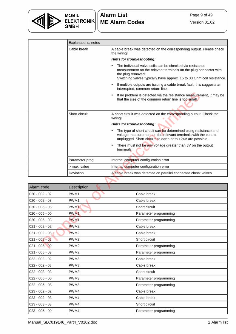
Alarm List Page 9 of 49
ME Alarm Codes Version 01.02
Manual_SLC019146_Part4_V0102.doc 2 Alarm list
Explanations, notes
Cable break A cable break was detected on the corresponding output. Please check the wiring!
Hints for troubleshooting:
• The individual valve coils can be checked via resistance measurement on the relevant terminals on the plug connector with the plug removed: Switching valves typically have approx. 15 to 30 Ohm coil resistance.
• If multiple outputs are issuing a cable break fault, this suggests an interrupted, common return line.
• If no problem is detected via the resistance measurement, it may be that the size of the common return line is too small.
Short circuit A short circuit was detected on the corresponding output. Check the wiring!
Hints for troubleshooting:
• The type of short circuit can be determined using resistance and voltage measurement on the relevant terminals with the control unplugged. Short circuits to earth or to +24V are possible.
• There must not be any voltage greater than 3V on the output terminals!
Parameter prog Internal computer configuration error
> max. value Internal computer configuration error
Deviation A cable break was detected on parallel connected check valves.
Alarm code Description
020 - 002 - 02 PWM1 Cable break
020 - 002 - 03 PWM1 Cable break
020 - 003 - 03 PWM1 Short circuit
020 - 005 - 00 PWM1 Parameter programming
020 - 005 - 03 PWM1 Parameter programming
021 - 002 - 02 PWM2 Cable break
021 - 002 - 03 PWM2 Cable break
021 - 003 - 03 PWM2 Short circuit
021 - 005 - 00 PWM2 Parameter programming
021 - 005 - 03 PWM2 Parameter programming
022 - 002 - 02 PWM3 Cable break
022 - 002 - 03 PWM3 Cable break
022 - 003 - 03 PWM3 Short circuit
022 - 005 - 00 PWM3 Parameter programming
022 - 005 - 03 PWM3 Parameter programming
023 - 002 - 02 PWM4 Cable break
023 - 002 - 03 PWM4 Cable break
023 - 003 - 03 PWM4 Short circuit
023 - 005 - 00 PWM4 Parameter programming
Prope
rty o
f Am
erica
n Airli
nes
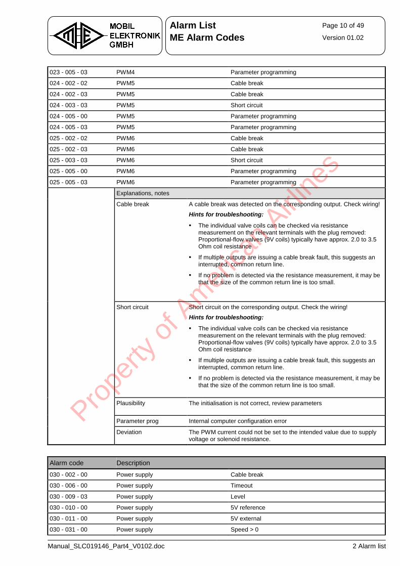
Alarm List Page 10 of 49
ME Alarm Codes Version 01.02
Manual_SLC019146_Part4_V0102.doc 2 Alarm list
023 - 005 - 03 PWM4 Parameter programming
024 - 002 - 02 PWM5 Cable break
024 - 002 - 03 PWM5 Cable break
024 - 003 - 03 PWM5 Short circuit
024 - 005 - 00 PWM5 Parameter programming
024 - 005 - 03 PWM5 Parameter programming
025 - 002 - 02 PWM6 Cable break
025 - 002 - 03 PWM6 Cable break
025 - 003 - 03 PWM6 Short circuit
025 - 005 - 00 PWM6 Parameter programming
025 - 005 - 03 PWM6 Parameter programming
Explanations, notes
Cable break A cable break was detected on the corresponding output. Check wiring!
Hints for troubleshooting:
• The individual valve coils can be checked via resistance measurement on the relevant terminals with the plug removed: Proportional-flow valves (9V coils) typically have approx. 2.0 to 3.5 Ohm coil resistance
• If multiple outputs are issuing a cable break fault, this suggests an interrupted, common return line.
• If no problem is detected via the resistance measurement, it may be that the size of the common return line is too small.
Short circuit Short circuit on the corresponding output. Check the wiring!
Hints for troubleshooting:
• The individual valve coils can be checked via resistance measurement on the relevant terminals with the plug removed: Proportional-flow valves (9V coils) typically have approx. 2.0 to 3.5 Ohm coil resistance
• If multiple outputs are issuing a cable break fault, this suggests an interrupted, common return line.
• If no problem is detected via the resistance measurement, it may be that the size of the common return line is too small.
Plausibility The initialisation is not correct, review parameters
Parameter prog Internal computer configuration error
Deviation The PWM current could not be set to the intended value due to supply voltage or solenoid resistance.
Alarm code Description
030 - 002 - 00 Power supply Cable break
030 - 006 - 00 Power supply Timeout
030 - 009 - 03 Power supply Level
030 - 010 - 00 Power supply 5V reference
030 - 011 - 00 Power supply 5V external
030 - 031 - 00 Power supply Speed > 0
Prope
rty o
f Am
erica
n Airli
nes
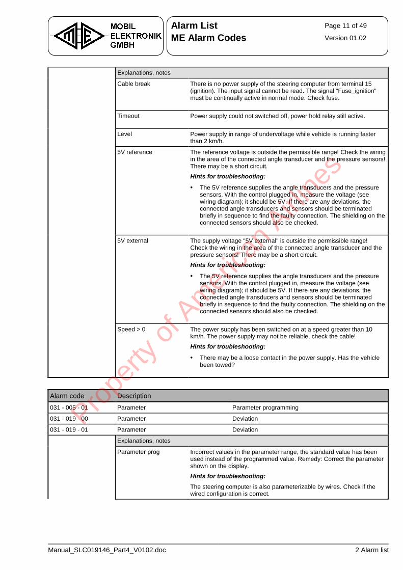
Alarm List Page 11 of 49
ME Alarm Codes Version 01.02
Manual_SLC019146_Part4_V0102.doc 2 Alarm list
Explanations, notes
Cable break There is no power supply of the steering computer from terminal 15 (ignition). The input signal cannot be read. The signal "Fuse_ignition" must be continually active in normal mode. Check fuse.
Timeout Power supply could not switched off, power hold relay still active.
Level Power supply in range of undervoltage while vehicle is running faster than 2 km/h.
5V reference The reference voltage is outside the permissible range! Check the wiring in the area of the connected angle transducer and the pressure sensors! There may be a short circuit.
Hints for troubleshooting:
• The 5V reference supplies the angle transducers and the pressure sensors. With the control plugged in, measure the voltage (see wiring diagram); it should be 5V. If there are any deviations, the connected angle transducers and sensors should be terminated briefly in sequence to find the faulty connection. The shielding on the connected sensors should also be checked.
5V external The supply voltage "5V external" is outside the permissible range! Check the wiring in the area of the connected angle transducer and the pressure sensors! There may be a short circuit.
Hints for troubleshooting:
• The 5V reference supplies the angle transducers and the pressure sensors. With the control plugged in, measure the voltage (see wiring diagram); it should be 5V. If there are any deviations, the connected angle transducers and sensors should be terminated briefly in sequence to find the faulty connection. The shielding on the connected sensors should also be checked.
Speed > 0 The power supply has been switched on at a speed greater than 10 km/h. The power supply may not be reliable, check the cable!
Hints for troubleshooting:
• There may be a loose contact in the power supply. Has the vehicle been towed?
Alarm code Description
031 - 005 - 01 Parameter Parameter programming
031 - 019 - 00 Parameter Deviation
031 - 019 - 01 Parameter Deviation
Explanations, notes
Parameter prog Incorrect values in the parameter range, the standard value has been used instead of the programmed value. Remedy: Correct the parameter shown on the display.
Hints for troubleshooting:
The steering computer is also parameterizable by wires. Check if the wired configuration is correct.
Prope
rty o
f Am
erica
n Airli
nes
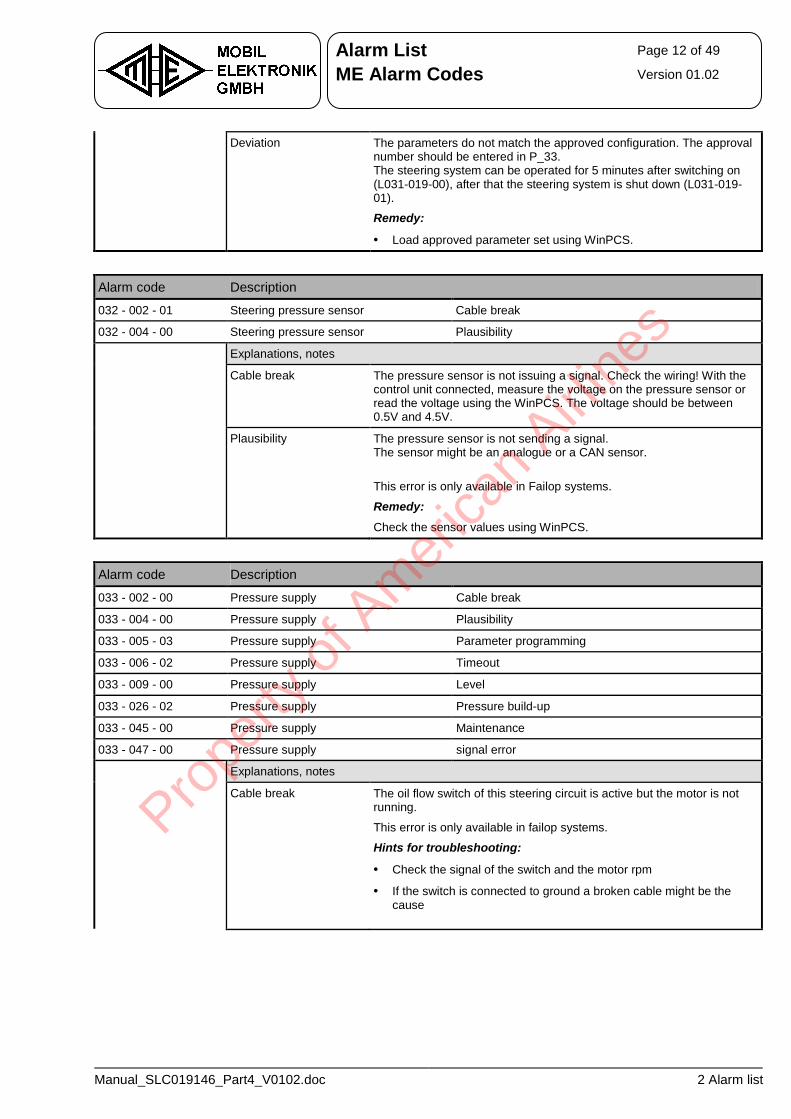
Alarm List Page 12 of 49
ME Alarm Codes Version 01.02
Manual_SLC019146_Part4_V0102.doc 2 Alarm list
Deviation The parameters do not match the approved configuration. The approval number should be entered in P_33. The steering system can be operated for 5 minutes after switching on (L031-019-00), after that the steering system is shut down (L031-019-01).
Remedy:
• Load approved parameter set using WinPCS.
Alarm code Description
032 - 002 - 01 Steering pressure sensor Cable break
032 - 004 - 00 Steering pressure sensor Plausibility
Explanations, notes
Cable break The pressure sensor is not issuing a signal. Check the wiring! With the control unit connected, measure the voltage on the pressure sensor or read the voltage using the WinPCS. The voltage should be between 0.5V and 4.5V.
Plausibility The pressure sensor is not sending a signal. The sensor might be an analogue or a CAN sensor.
This error is only available in Failop systems.
Remedy:
Check the sensor values using WinPCS.
Alarm code Description
033 - 002 - 00 Pressure supply Cable break
033 - 004 - 00 Pressure supply Plausibility
033 - 005 - 03 Pressure supply Parameter programming
033 - 006 - 02 Pressure supply Timeout
033 - 009 - 00 Pressure supply Level
033 - 026 - 02 Pressure supply Pressure build-up
033 - 045 - 00 Pressure supply Maintenance
033 - 047 - 00 Pressure supply signal error
Explanations, notes
Cable break The oil flow switch of this steering circuit is active but the motor is not running.
This error is only available in failop systems.
Hints for troubleshooting:
• Check the signal of the switch and the motor rpm
• If the switch is connected to ground a broken cable might be the cause
Prope
rty o
f Am
erica
n Airli
nes
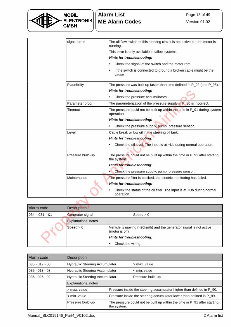
Alarm List Page 13 of 49
ME Alarm Codes Version 01.02
Manual_SLC019146_Part4_V0102.doc 2 Alarm list
signal error The oil flow switch of this steering circuit is not active but the motor is running.
This error is only available in failop systems.
Hints for troubleshooting:
• Check the signal of the switch and the motor rpm
• If the switch is connected to ground a broken cable might be the cause
Plausibility The pressure was built up faster than time defined in P_92 (and P_93).
Hints for troubleshooting:
• Check the pressure accumulators.
Parameter prog The parameterization of the pressure supply in P_80 is incorrect.
Timeout The pressure could not be built up within the time in P_91 during system operation.
Hints for troubleshooting:
• Check the pressure supply, pump, pressure sensor.
Level Cable break or low oil in the steering oil tank.
Hints for troubleshooting:
• Check the oil level. The input is at +Ub during normal operation.
Pressure build-up The pressure could not be built up within the time in P_91 after starting the system.
Hints for troubleshooting:
• Check the pressure supply, pump, pressure sensor.
Maintenance The pressure filter is blocked, the electric monitoring has failed.
Hints for troubleshooting:
• Check the status of the oil filter. The input is at +Ub during normal operation.
Alarm code Description
034 – 031 – 01 Generator signal Speed > 0
Explanations, notes
Speed > 0 Vehicle is moving (>20km/h) and the generator signal is not active (motor is off).
Hints for troubleshooting:
• Check the wiring.
Alarm code Description
035 - 012 - 00 Hydraulic Steering Accumulator > max. value
035 - 013 - 03 Hydraulic Steering Accumulator < min. value
035 - 026 - 02 Hydraulic Steering Accumulator Pressure build-up
Explanations, notes
> max. value Pressure inside the steering accumulator higher than defined in P_90.
< min. value Pressure inside the steering accumulator lower than defined in P_89.
Pressure build-up The pressure could not be built up within the time in P_91 after starting the system.
Prope
rty o
f Am
erica
n Airli
nes
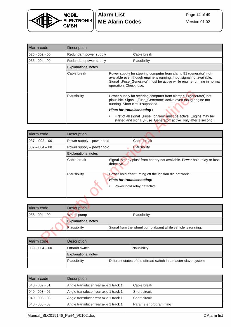
Alarm List Page 14 of 49
ME Alarm Codes Version 01.02
Manual_SLC019146_Part4_V0102.doc 2 Alarm list
Alarm code Description
036 - 002 - 00 Redundant power supply Cable break
036 - 004 - 00 Redundant power supply Plausibility
Explanations, notes
Cable break Power supply for steering computer from clamp 91 (generator) not available even though engine is running. Input signal not available. Signal „Fuse_Generator“ must be active while engine running in normal operation. Check fuse.
Plausibility Power supply for steering computer from clamp 91 (generator) not plausible. Signal „Fuse_Generator“ active even thoug engine not running. Short circuit supposed.
Hints for troubleshooting :
• First of all signal „Fuse_Ignition“ must be active. Engine may be started and signal „Fuse_Generator“ active only after 1 second.
Alarm code Description
037 – 002 – 00 Power supply – power hold Cable break
037 – 004 – 00 Power supply – power hold Plausibility
Explanations, notes
Cable break Signal “steady plus“ from battery not available. Power hold relay or fuse defective.
Plausibility Power hold after turning off the ignition did not work. Hints for troubleshooting:
• Power hold relay defective
Alarm code Description
038 - 004 - 00 Wheel pump Plausibility
Explanations, notes
Plausibility Signal from the wheel pump absent while vehicle is running.
Alarm code Description
039 – 004 – 00 Offroad switch Plausibility
Explanations, notes
Plausibility Different states of the offroad switch in a master-slave-system.
Alarm code Description
040 - 002 - 01 Angle transducer rear axle 1 track 1 Cable break
040 - 003 - 02 Angle transducer rear axle 1 track 1 Short circuit
040 - 003 - 03 Angle transducer rear axle 1 track 1 Short circuit
040 - 005 - 03 Angle transducer rear axle 1 track 1 Parameter programming
Prope
rty o
f Am
erica
n Airli
nes
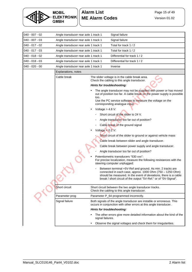
Alarm List Page 15 of 49
ME Alarm Codes Version 01.02
Manual_SLC019146_Part4_V0102.doc 2 Alarm list
040 - 007 - 02 Angle transducer rear axle 1 track 1 Signal failure
040 - 007 - 03 Angle transducer rear axle 1 track 1 Signal failure
040 - 017 - 02 Angle transducer rear axle 1 track 1 Total for track 1 / 2
040 - 017 - 03 Angle transducer rear axle 1 track 1 Total for track 1 / 2
040 - 018 - 02 Angle transducer rear axle 1 track 1 Differential for track 1 / 2
040 - 018 - 03 Angle transducer rear axle 1 track 1 Differential for track 1 / 2
040 - 020 - 00 Angle transducer rear axle 1 track 1 Inverse
Explanations, notes
Cable break The slider voltage is in the cable break area. Check the cabling to this angle transducer.
Hints for troubleshooting:
• The angle transducer may not be supplied with power or has moved out of position too far. A cable break on the power supply is possible too. Use the PC service software to measure the voltage on the corresponding analogue input.
• Voltage > 4.8 V:
- Short circuit of the slider to 24 V.
- Angle transducer too far out of position?
- Cable break of the ground signal
• Voltage < 0.2 V:
- Short circuit of the slider to ground or against vehicle mass
- Cable break between slider and angle transducer.
- Cable break between power supply and angle transducer.
- Angle transducer too far out of position?
• Potentiometric transducers “530 xxx”: For precise localization, measure the following resistances with the steering computer unplugged:
- Between terminal +5V-Ref and ground. As min. 2 tracks are connected in each case, approx. 1000 Ohm (750 – 1250 Ohm) should be measured. In the event of deviations, there is a cable break / short circuit of the output "5V-Ref." or of "0V-Signal".
Short circuit Short circuit between the two angle transducer tracks. Check the cabling to this angle transducer.
Parameter prog Parameter P_64 programmed incorrectly.
Signal failure Both signals of the angle transducer are instable or erroneous. This occurs in conjunction with other errors at this angle transducer.
Hints for troubleshooting:
• The other errors give more detailed information about the kind of the signal failures.
• Observe the signal voltages and check them for irregularities.
Prope
rty o
f Am
erica
n Airli
nes
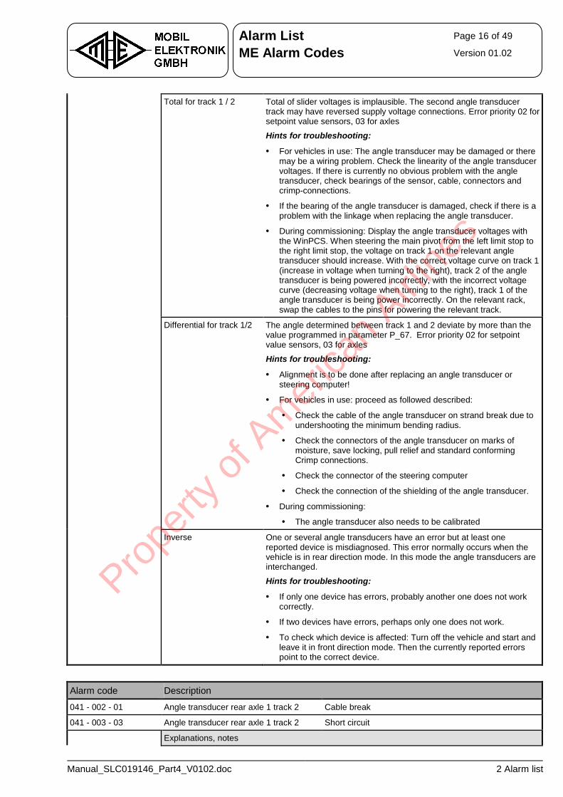
Alarm List Page 16 of 49
ME Alarm Codes Version 01.02
Manual_SLC019146_Part4_V0102.doc 2 Alarm list
Total for track 1 / 2 Total of slider voltages is implausible. The second angle transducer track may have reversed supply voltage connections. Error priority 02 for setpoint value sensors, 03 for axles
Hints for troubleshooting:
• For vehicles in use: The angle transducer may be damaged or there may be a wiring problem. Check the linearity of the angle transducer voltages. If there is currently no obvious problem with the angle transducer, check bearings of the sensor, cable, connectors and crimp-connections.
• If the bearing of the angle transducer is damaged, check if there is a problem with the linkage when replacing the angle transducer.
• During commissioning: Display the angle transducer voltages with the WinPCS. When steering the main pivot from the left limit stop to the right limit stop, the voltage on track 1 on the relevant angle transducer should increase. With the correct voltage curve on track 1 (increase in voltage when turning to the right), track 2 of the angle transducer is being powered incorrectly, with the incorrect voltage curve (decreasing voltage when turning to the right), track 1 of the angle transducer is being power incorrectly. On the relevant rack, swap the cables to the pins for powering the relevant track.
Differential for track 1/2 The angle determined between track 1 and 2 deviate by more than the value programmed in parameter P_67. Error priority 02 for setpoint value sensors, 03 for axles
Hints for troubleshooting:
• Alignment is to be done after replacing an angle transducer or steering computer!
• For vehicles in use: proceed as followed described:
• Check the cable of the angle transducer on strand break due to undershooting the minimum bending radius.
• Check the connectors of the angle transducer on marks of moisture, save locking, pull relief and standard conforming Crimp connections.
• Check the connector of the steering computer
• Check the connection of the shielding of the angle transducer.
• During commissioning:
• The angle transducer also needs to be calibrated
Inverse One or several angle transducers have an error but at least one reported device is misdiagnosed. This error normally occurs when the vehicle is in rear direction mode. In this mode the angle transducers are interchanged.
Hints for troubleshooting:
• If only one device has errors, probably another one does not work correctly.
• If two devices have errors, perhaps only one does not work.
• To check which device is affected: Turn off the vehicle and start and leave it in front direction mode. Then the currently reported errors point to the correct device.
Alarm code Description
041 - 002 - 01 Angle transducer rear axle 1 track 2 Cable break
041 - 003 - 03 Angle transducer rear axle 1 track 2 Short circuit
Explanations, notes
Prope
rty o
f Am
erica
n Airli
nes
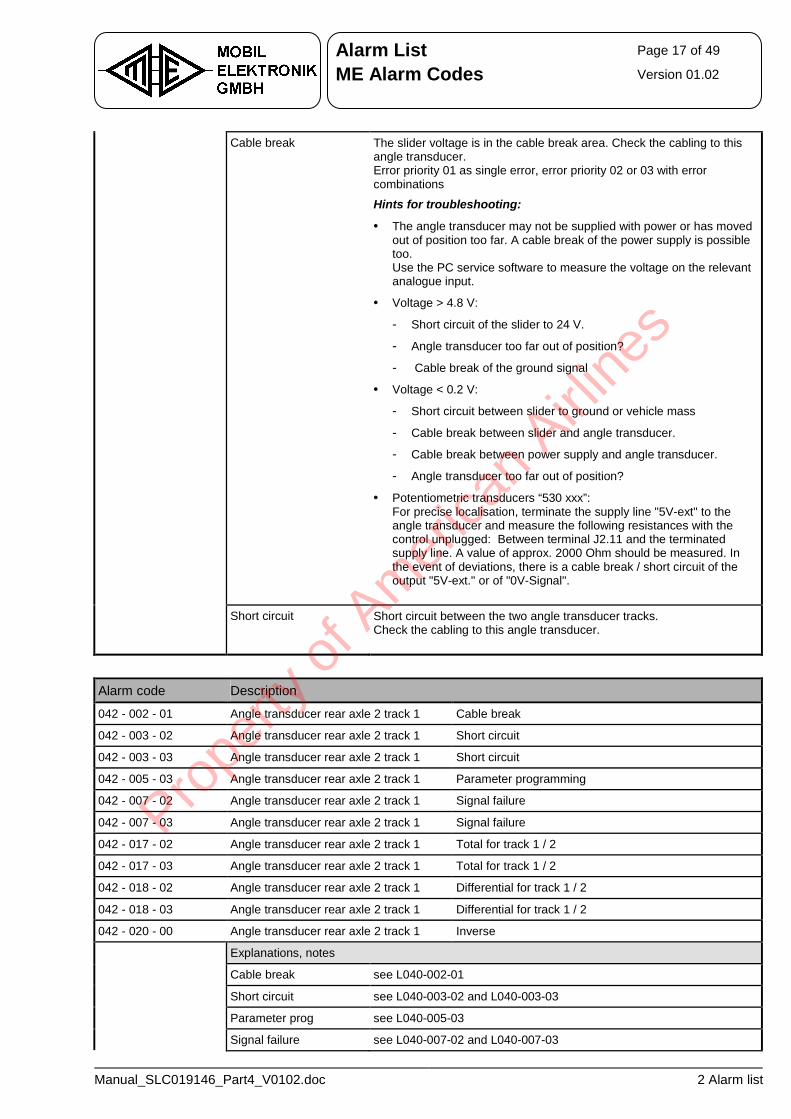
Alarm List Page 17 of 49
ME Alarm Codes Version 01.02
Manual_SLC019146_Part4_V0102.doc 2 Alarm list
Cable break The slider voltage is in the cable break area. Check the cabling to this angle transducer. Error priority 01 as single error, error priority 02 or 03 with error combinations
Hints for troubleshooting:
• The angle transducer may not be supplied with power or has moved out of position too far. A cable break of the power supply is possible too. Use the PC service software to measure the voltage on the relevant analogue input.
• Voltage > 4.8 V:
- Short circuit of the slider to 24 V.
- Angle transducer too far out of position?
- Cable break of the ground signal
• Voltage < 0.2 V:
- Short circuit between slider to ground or vehicle mass
- Cable break between slider and angle transducer.
- Cable break between power supply and angle transducer.
- Angle transducer too far out of position?
• Potentiometric transducers “530 xxx”: For precise localisation, terminate the supply line "5V-ext" to the angle transducer and measure the following resistances with the control unplugged: Between terminal J2.11 and the terminated supply line. A value of approx. 2000 Ohm should be measured. In the event of deviations, there is a cable break / short circuit of the output "5V-ext." or of "0V-Signal".
Short circuit Short circuit between the two angle transducer tracks. Check the cabling to this angle transducer.
Alarm code Description
042 - 002 - 01 Angle transducer rear axle 2 track 1 Cable break
042 - 003 - 02 Angle transducer rear axle 2 track 1 Short circuit
042 - 003 - 03 Angle transducer rear axle 2 track 1 Short circuit
042 - 005 - 03 Angle transducer rear axle 2 track 1 Parameter programming
042 - 007 - 02 Angle transducer rear axle 2 track 1 Signal failure
042 - 007 - 03 Angle transducer rear axle 2 track 1 Signal failure
042 - 017 - 02 Angle transducer rear axle 2 track 1 Total for track 1 / 2
042 - 017 - 03 Angle transducer rear axle 2 track 1 Total for track 1 / 2
042 - 018 - 02 Angle transducer rear axle 2 track 1 Differential for track 1 / 2
042 - 018 - 03 Angle transducer rear axle 2 track 1 Differential for track 1 / 2
042 - 020 - 00 Angle transducer rear axle 2 track 1 Inverse
Explanations, notes
Cable break see L040-002-01
Short circuit see L040-003-02 and L040-003-03
Parameter prog see L040-005-03
Signal failure see L040-007-02 and L040-007-03
Prope
rty o
f Am
erica
n Airli
nes
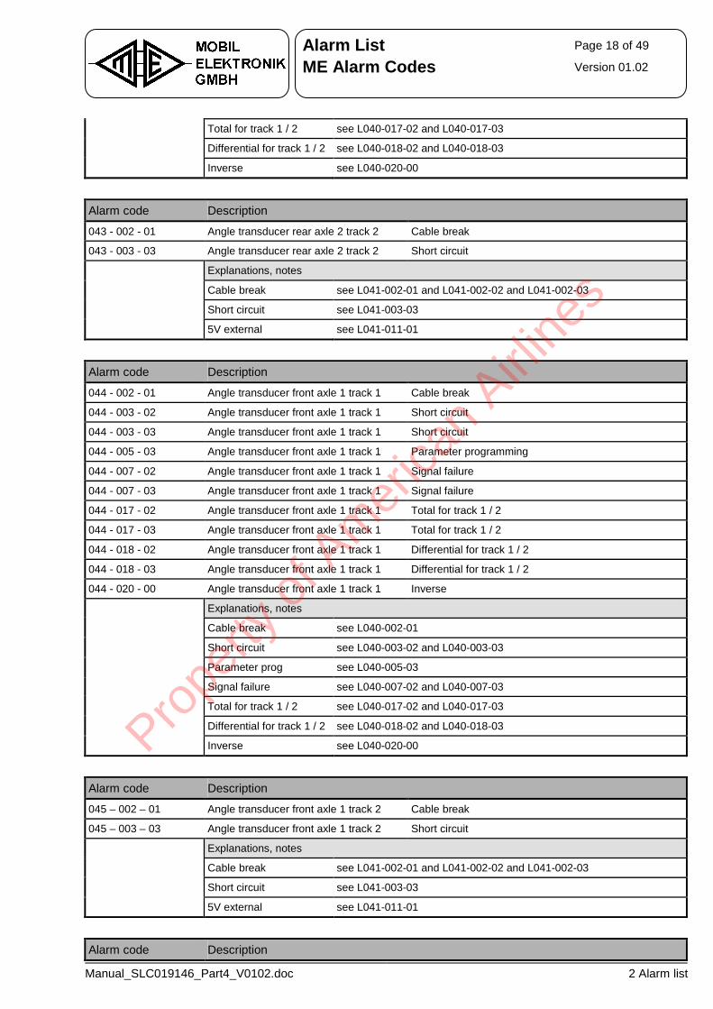
Alarm List Page 18 of 49
ME Alarm Codes Version 01.02
Manual_SLC019146_Part4_V0102.doc 2 Alarm list
Total for track 1 / 2 see L040-017-02 and L040-017-03
Differential for track 1 / 2 see L040-018-02 and L040-018-03
Inverse see L040-020-00
Alarm code Description
043 - 002 - 01 Angle transducer rear axle 2 track 2 Cable break
043 - 003 - 03 Angle transducer rear axle 2 track 2 Short circuit
Explanations, notes
Cable break see L041-002-01 and L041-002-02 and L041-002-03
Short circuit see L041-003-03
5V external see L041-011-01
Alarm code Description
044 - 002 - 01 Angle transducer front axle 1 track 1 Cable break
044 - 003 - 02 Angle transducer front axle 1 track 1 Short circuit
044 - 003 - 03 Angle transducer front axle 1 track 1 Short circuit
044 - 005 - 03 Angle transducer front axle 1 track 1 Parameter programming
044 - 007 - 02 Angle transducer front axle 1 track 1 Signal failure
044 - 007 - 03 Angle transducer front axle 1 track 1 Signal failure
044 - 017 - 02 Angle transducer front axle 1 track 1 Total for track 1 / 2
044 - 017 - 03 Angle transducer front axle 1 track 1 Total for track 1 / 2
044 - 018 - 02 Angle transducer front axle 1 track 1 Differential for track 1 / 2
044 - 018 - 03 Angle transducer front axle 1 track 1 Differential for track 1 / 2
044 - 020 - 00 Angle transducer front axle 1 track 1 Inverse
Explanations, notes
Cable break see L040-002-01
Short circuit see L040-003-02 and L040-003-03
Parameter prog see L040-005-03
Signal failure see L040-007-02 and L040-007-03
Total for track 1 / 2 see L040-017-02 and L040-017-03
Differential for track 1 / 2 see L040-018-02 and L040-018-03
Inverse see L040-020-00
Alarm code Description
045 – 002 – 01 Angle transducer front axle 1 track 2 Cable break
045 – 003 – 03 Angle transducer front axle 1 track 2 Short circuit
Explanations, notes
Cable break see L041-002-01 and L041-002-02 and L041-002-03
Short circuit see L041-003-03
5V external see L041-011-01
Alarm code Description
Prope
rty o
f Am
erica
n Airli
nes
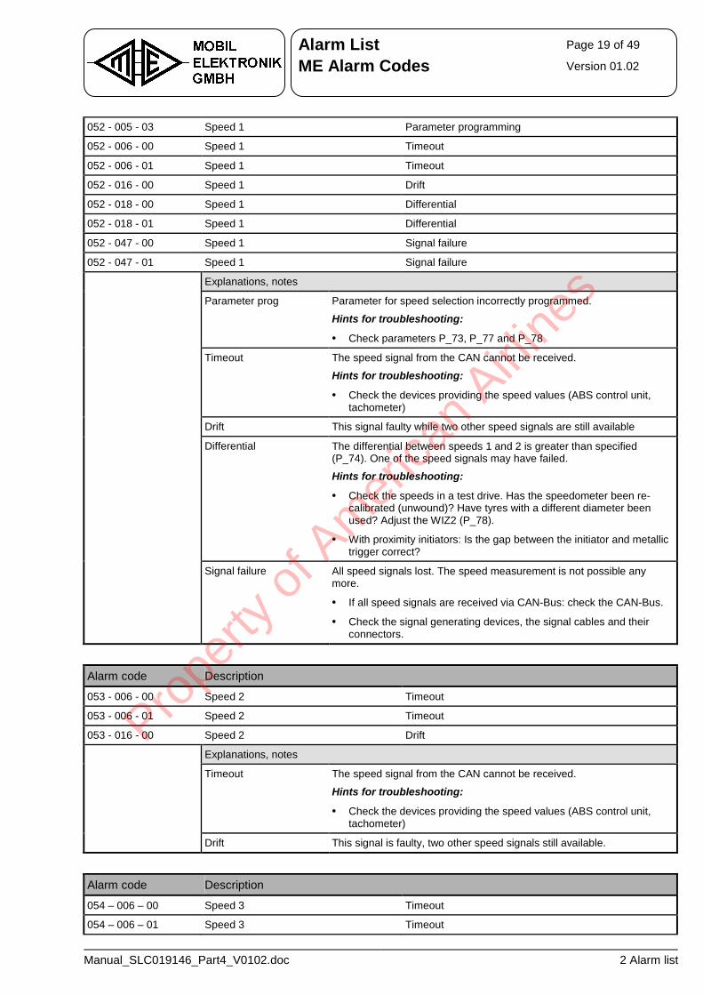
Alarm List Page 19 of 49
ME Alarm Codes Version 01.02
Manual_SLC019146_Part4_V0102.doc 2 Alarm list
052 - 005 - 03 Speed 1 Parameter programming
052 - 006 - 00 Speed 1 Timeout
052 - 006 - 01 Speed 1 Timeout
052 - 016 - 00 Speed 1 Drift
052 - 018 - 00 Speed 1 Differential
052 - 018 - 01 Speed 1 Differential
052 - 047 - 00 Speed 1 Signal failure
052 - 047 - 01 Speed 1 Signal failure
Explanations, notes
Parameter prog Parameter for speed selection incorrectly programmed.
Hints for troubleshooting:
• Check parameters P_73, P_77 and P_78
Timeout The speed signal from the CAN cannot be received.
Hints for troubleshooting:
• Check the devices providing the speed values (ABS control unit, tachometer)
Drift This signal faulty while two other speed signals are still available
Differential The differential between speeds 1 and 2 is greater than specified (P_74). One of the speed signals may have failed.
Hints for troubleshooting:
• Check the speeds in a test drive. Has the speedometer been re-calibrated (unwound)? Have tyres with a different diameter been used? Adjust the WIZ2 (P_78).
• With proximity initiators: Is the gap between the initiator and metallic trigger correct?
Signal failure All speed signals lost. The speed measurement is not possible any more.
• If all speed signals are received via CAN-Bus: check the CAN-Bus.
• Check the signal generating devices, the signal cables and their connectors.
Alarm code Description
053 - 006 - 00 Speed 2 Timeout
053 - 006 - 01 Speed 2 Timeout
053 - 016 - 00 Speed 2 Drift
Explanations, notes
Timeout The speed signal from the CAN cannot be received.
Hints for troubleshooting:
• Check the devices providing the speed values (ABS control unit, tachometer)
Drift This signal is faulty, two other speed signals still available.
Alarm code Description
054 – 006 – 00 Speed 3 Timeout
054 – 006 – 01 Speed 3 Timeout
Prope
rty o
f Am
erica
n Airli
nes
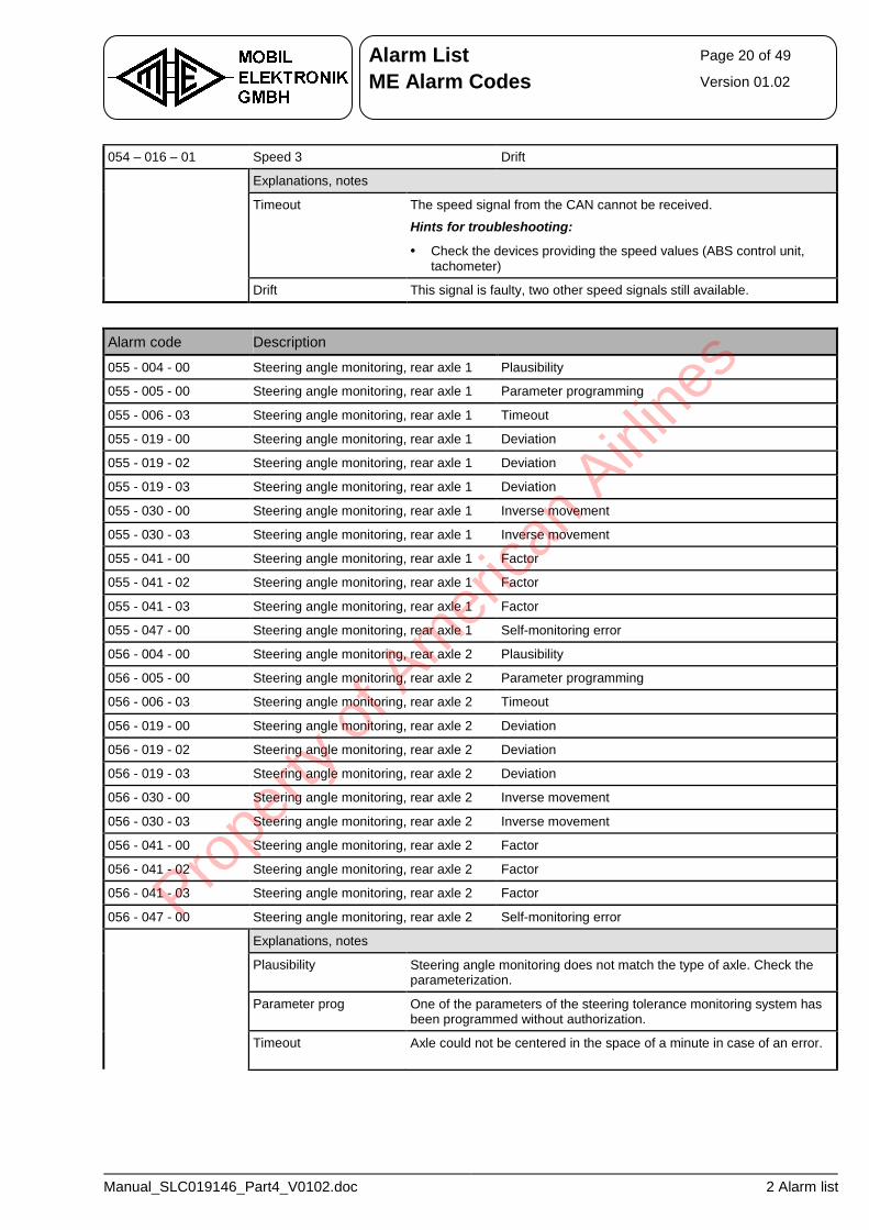
Alarm List Page 20 of 49
ME Alarm Codes Version 01.02
Manual_SLC019146_Part4_V0102.doc 2 Alarm list
054 – 016 – 01 Speed 3 Drift
Explanations, notes
Timeout The speed signal from the CAN cannot be received.
Hints for troubleshooting:
• Check the devices providing the speed values (ABS control unit, tachometer)
Drift This signal is faulty, two other speed signals still available.
Alarm code Description
055 - 004 - 00 Steering angle monitoring, rear axle 1 Plausibility
055 - 005 - 00 Steering angle monitoring, rear axle 1 Parameter programming
055 - 006 - 03 Steering angle monitoring, rear axle 1 Timeout
055 - 019 - 00 Steering angle monitoring, rear axle 1 Deviation
055 - 019 - 02 Steering angle monitoring, rear axle 1 Deviation
055 - 019 - 03 Steering angle monitoring, rear axle 1 Deviation
055 - 030 - 00 Steering angle monitoring, rear axle 1 Inverse movement
055 - 030 - 03 Steering angle monitoring, rear axle 1 Inverse movement
055 - 041 - 00 Steering angle monitoring, rear axle 1 Factor
055 - 041 - 02 Steering angle monitoring, rear axle 1 Factor
055 - 041 - 03 Steering angle monitoring, rear axle 1 Factor
055 - 047 - 00 Steering angle monitoring, rear axle 1 Self-monitoring error
056 - 004 - 00 Steering angle monitoring, rear axle 2 Plausibility
056 - 005 - 00 Steering angle monitoring, rear axle 2 Parameter programming
056 - 006 - 03 Steering angle monitoring, rear axle 2 Timeout
056 - 019 - 00 Steering angle monitoring, rear axle 2 Deviation
056 - 019 - 02 Steering angle monitoring, rear axle 2 Deviation
056 - 019 - 03 Steering angle monitoring, rear axle 2 Deviation
056 - 030 - 00 Steering angle monitoring, rear axle 2 Inverse movement
056 - 030 - 03 Steering angle monitoring, rear axle 2 Inverse movement
056 - 041 - 00 Steering angle monitoring, rear axle 2 Factor
056 - 041 - 02 Steering angle monitoring, rear axle 2 Factor
056 - 041 - 03 Steering angle monitoring, rear axle 2 Factor
056 - 047 - 00 Steering angle monitoring, rear axle 2 Self-monitoring error
Explanations, notes
Plausibility Steering angle monitoring does not match the type of axle. Check the parameterization.
Parameter prog One of the parameters of the steering tolerance monitoring system has been programmed without authorization.
Timeout Axle could not be centered in the space of a minute in case of an error.
Prope
rty o
f Am
erica
n Airli
nes
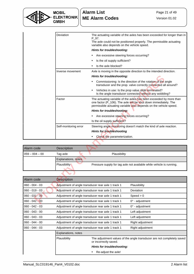
Alarm List Page 21 of 49
ME Alarm Codes Version 01.02
Manual_SLC019146_Part4_V0102.doc 2 Alarm list
Deviation The actuating variable of the axles has been exceeded for longer than in P_97. The axle could not be positioned properly. The permissible actuating variable also depends on the vehicle speed.
Hints for troubleshooting:
• Are excessive steering forces occurring?
• Is the oil supply sufficient?
• Is the axle blocked?
Inverse movement Axle is moving in the opposite direction to the intended direction.
Hints for troubleshooting:
• Commissioning: Is the direction of the rotation of the angle transducer and the prop. valve correctly connected all around?
• Vehicles in use: Is the prop value slide terminated? Is the angle transducer connected without any wobbling?
Factor The actuating variable of the axles has been exceeded by more than one factor (P_106). The axle will be shut down immediately. The permissible actuating variable also depends on the vehicle speed.
Hints for troubleshooting:
• Are excessive steering forces occurring?
Is the oil supply sufficient?
Self-monitoring error Steering angle monitoring doesn't match the kind of axle reaction.
Hints for troubleshooting
• Check the parameterization.
Alarm code Description
059 – 004 – 00 Tag axle Plausibility
Explanations, notes
Plausibility Pressure supply for tag axle not available while vehicle is running.
Alarm code Description
060 - 004 - 03 Adjustment of angle transducer rear axle 1 track 1 Plausibility
060 - 019 - 03 Adjustment of angle transducer rear axle 1 track 1 Deviation
060 - 031 - 00 Adjustment of angle transducer rear axle 1 track 1 Speed > 0
060 - 042 - 00 Adjustment of angle transducer rear axle 1 track 1 0° - adjustment
060 - 042 - 03 Adjustment of angle transducer rear axle 1 track 1 0° - adjustment
060 - 043 - 00 Adjustment of angle transducer rear axle 1 track 1 Left adjustment
060 - 043 - 03 Adjustment of angle transducer rear axle 1 track 1 Left adjustment
060 - 044 - 00 Adjustment of angle transducer rear axle 1 track 1 Right adjustment
060 - 044 - 03 Adjustment of angle transducer rear axle 1 track 1 Right adjustment
Explanations, notes
Plausibility The adjustment values of the angle transducer are not completely saved or incorrectly saved.
Hints for troubleshooting:
• Re-adjust the axle!
Prope
rty o
f Am
erica
n Airli
nes
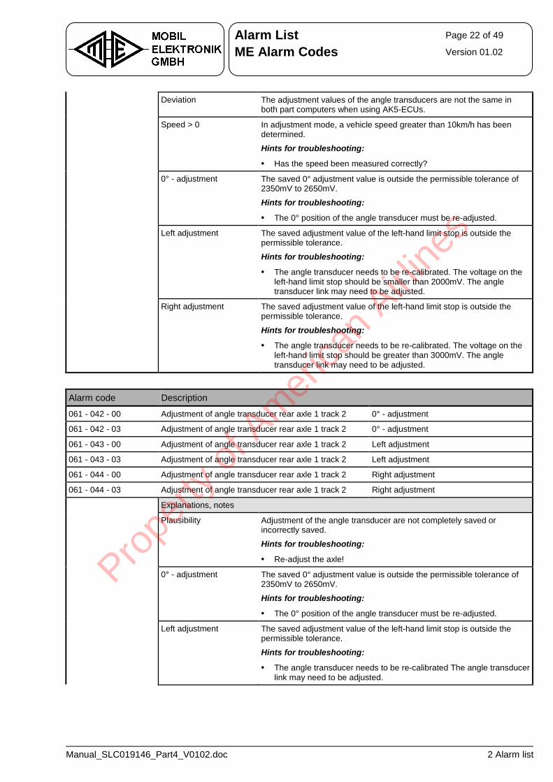
Alarm List Page 22 of 49
ME Alarm Codes Version 01.02
Manual_SLC019146_Part4_V0102.doc 2 Alarm list
Deviation The adjustment values of the angle transducers are not the same in both part computers when using AK5-ECUs.
Speed > 0 In adjustment mode, a vehicle speed greater than 10km/h has been determined.
Hints for troubleshooting:
• Has the speed been measured correctly?
0° - adjustment The saved 0° adjustment value is outside the permissible tolerance of 2350mV to 2650mV.
Hints for troubleshooting:
• The 0° position of the angle transducer must be re-adjusted.
Left adjustment The saved adjustment value of the left-hand limit stop is outside the permissible tolerance.
Hints for troubleshooting:
• The angle transducer needs to be re-calibrated. The voltage on the left-hand limit stop should be smaller than 2000mV. The angle transducer link may need to be adjusted.
Right adjustment The saved adjustment value of the left-hand limit stop is outside the permissible tolerance.
Hints for troubleshooting:
• The angle transducer needs to be re-calibrated. The voltage on the left-hand limit stop should be greater than 3000mV. The angle transducer link may need to be adjusted.
Alarm code Description
061 - 042 - 00 Adjustment of angle transducer rear axle 1 track 2 0° - adjustment
061 - 042 - 03 Adjustment of angle transducer rear axle 1 track 2 0° - adjustment
061 - 043 - 00 Adjustment of angle transducer rear axle 1 track 2 Left adjustment
061 - 043 - 03 Adjustment of angle transducer rear axle 1 track 2 Left adjustment
061 - 044 - 00 Adjustment of angle transducer rear axle 1 track 2 Right adjustment
061 - 044 - 03 Adjustment of angle transducer rear axle 1 track 2 Right adjustment
Explanations, notes
Plausibility Adjustment of the angle transducer are not completely saved or incorrectly saved.
Hints for troubleshooting:
• Re-adjust the axle!
0° - adjustment The saved 0° adjustment value is outside the permissible tolerance of 2350mV to 2650mV.
Hints for troubleshooting:
• The 0° position of the angle transducer must be re-adjusted.
Left adjustment The saved adjustment value of the left-hand limit stop is outside the permissible tolerance.
Hints for troubleshooting:
• The angle transducer needs to be re-calibrated The angle transducer link may need to be adjusted.
Prope
rty o
f Am
erica
n Airli
nes
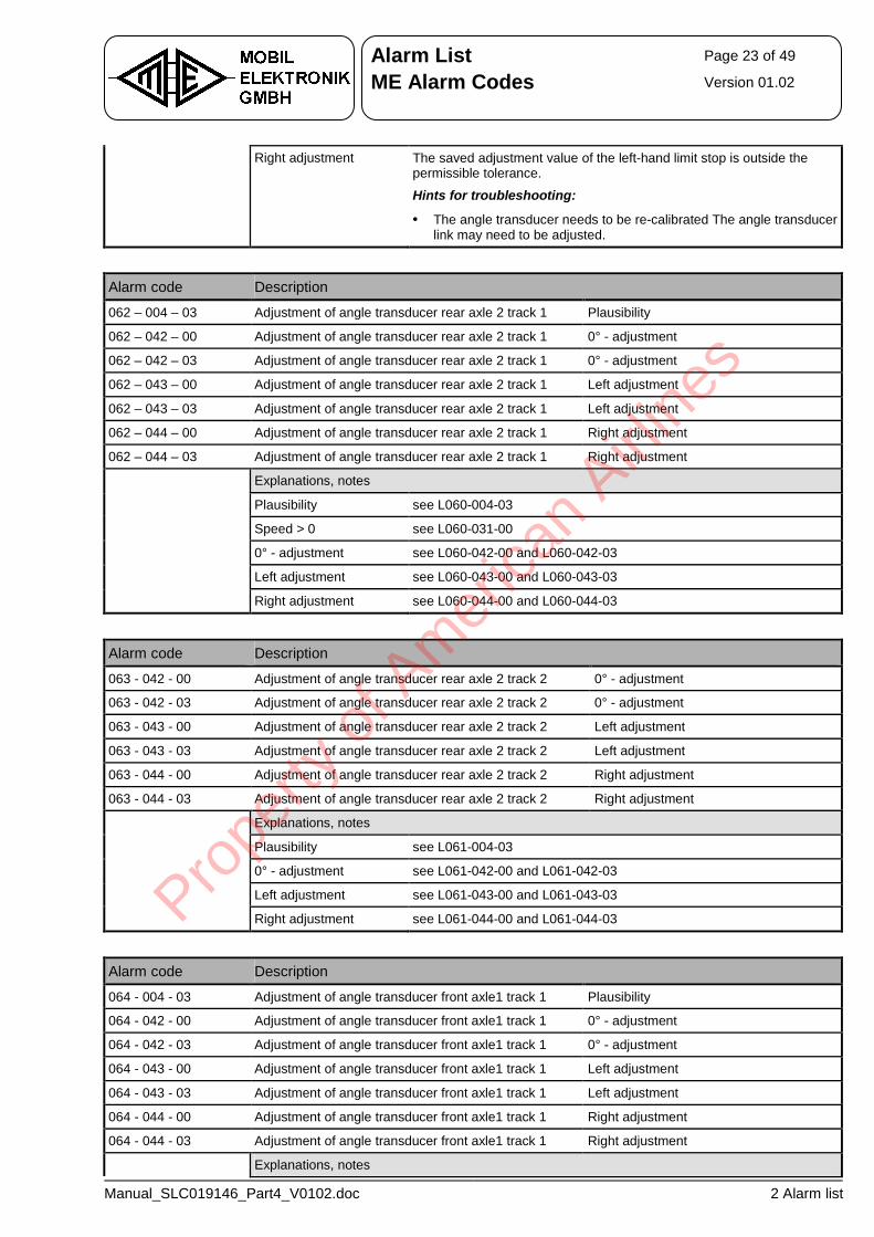
Alarm List Page 23 of 49
ME Alarm Codes Version 01.02
Manual_SLC019146_Part4_V0102.doc 2 Alarm list
Right adjustment The saved adjustment value of the left-hand limit stop is outside the permissible tolerance.
Hints for troubleshooting:
• The angle transducer needs to be re-calibrated The angle transducer link may need to be adjusted.
Alarm code Description
062 – 004 – 03 Adjustment of angle transducer rear axle 2 track 1 Plausibility
062 – 042 – 00 Adjustment of angle transducer rear axle 2 track 1 0° - adjustment
062 – 042 – 03 Adjustment of angle transducer rear axle 2 track 1 0° - adjustment
062 – 043 – 00 Adjustment of angle transducer rear axle 2 track 1 Left adjustment
062 – 043 – 03 Adjustment of angle transducer rear axle 2 track 1 Left adjustment
062 – 044 – 00 Adjustment of angle transducer rear axle 2 track 1 Right adjustment
062 – 044 – 03 Adjustment of angle transducer rear axle 2 track 1 Right adjustment
Explanations, notes
Plausibility see L060-004-03
Speed > 0 see L060-031-00
0° - adjustment see L060-042-00 and L060-042-03
Left adjustment see L060-043-00 and L060-043-03
Right adjustment see L060-044-00 and L060-044-03
Alarm code Description
063 - 042 - 00 Adjustment of angle transducer rear axle 2 track 2 0° - adjustment
063 - 042 - 03 Adjustment of angle transducer rear axle 2 track 2 0° - adjustment
063 - 043 - 00 Adjustment of angle transducer rear axle 2 track 2 Left adjustment
063 - 043 - 03 Adjustment of angle transducer rear axle 2 track 2 Left adjustment
063 - 044 - 00 Adjustment of angle transducer rear axle 2 track 2 Right adjustment
063 - 044 - 03 Adjustment of angle transducer rear axle 2 track 2 Right adjustment
Explanations, notes
Plausibility see L061-004-03
0° - adjustment see L061-042-00 and L061-042-03
Left adjustment see L061-043-00 and L061-043-03
Right adjustment see L061-044-00 and L061-044-03
Alarm code Description
064 - 004 - 03 Adjustment of angle transducer front axle1 track 1 Plausibility
064 - 042 - 00 Adjustment of angle transducer front axle1 track 1 0° - adjustment
064 - 042 - 03 Adjustment of angle transducer front axle1 track 1 0° - adjustment
064 - 043 - 00 Adjustment of angle transducer front axle1 track 1 Left adjustment
064 - 043 - 03 Adjustment of angle transducer front axle1 track 1 Left adjustment
064 - 044 - 00 Adjustment of angle transducer front axle1 track 1 Right adjustment
064 - 044 - 03 Adjustment of angle transducer front axle1 track 1 Right adjustment
Explanations, notes
Prope
rty o
f Am
erica
n Airli
nes
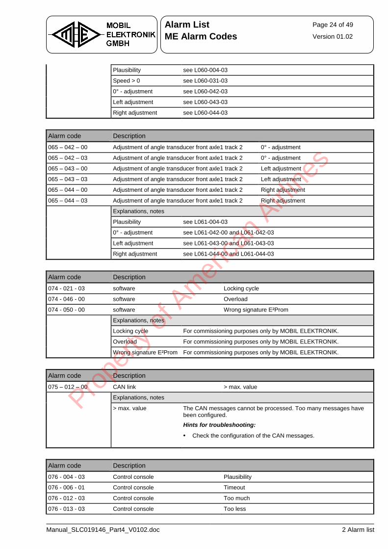
Alarm List Page 24 of 49
ME Alarm Codes Version 01.02
Manual_SLC019146_Part4_V0102.doc 2 Alarm list
Plausibility see L060-004-03
Speed > 0 see L060-031-03
0° - adjustment see L060-042-03
Left adjustment see L060-043-03
Right adjustment see L060-044-03
Alarm code Description
065 – 042 – 00 Adjustment of angle transducer front axle1 track 2 0° - adjustment
065 – 042 – 03 Adjustment of angle transducer front axle1 track 2 0° - adjustment
065 – 043 – 00 Adjustment of angle transducer front axle1 track 2 Left adjustment
065 – 043 – 03 Adjustment of angle transducer front axle1 track 2 Left adjustment
065 – 044 – 00 Adjustment of angle transducer front axle1 track 2 Right adjustment
065 – 044 – 03 Adjustment of angle transducer front axle1 track 2 Right adjustment
Explanations, notes
Plausibility see L061-004-03
0° - adjustment see L061-042-00 and L061-042-03
Left adjustment see L061-043-00 and L061-043-03
Right adjustment see L061-044-00 and L061-044-03
Alarm code Description
074 - 021 - 03 software Locking cycle
074 - 046 - 00 software Overload
074 - 050 - 00 software Wrong signature E²Prom
Explanations, notes
Locking cycle For commissioning purposes only by MOBIL ELEKTRONIK.
Overload For commissioning purposes only by MOBIL ELEKTRONIK.
Wrong signature E²Prom For commissioning purposes only by MOBIL ELEKTRONIK.
Alarm code Description
075 – 012 – 00 CAN link > max. value
Explanations, notes
> max. value The CAN messages cannot be processed. Too many messages have been configured.
Hints for troubleshooting:
• Check the configuration of the CAN messages.
Alarm code Description
076 - 004 - 03 Control console Plausibility
076 - 006 - 01 Control console Timeout
076 - 012 - 03 Control console Too much
076 - 013 - 03 Control console Too less
Prope
rty o
f Am
erica
n Airli
nes
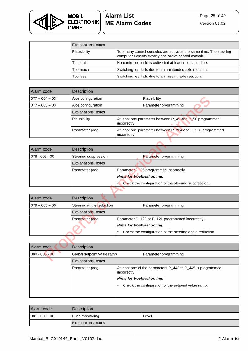
Alarm List Page 25 of 49
ME Alarm Codes Version 01.02
Manual_SLC019146_Part4_V0102.doc 2 Alarm list
Explanations, notes
Plausibility Too many control consoles are active at the same time. The steering computer expects exactly one active control console.
Timeout No control console is active but at least one should be.
Too much Switching test fails due to an unintended axle reaction.
Too less Switching test fails due to an missing axle reaction.
Alarm code Description
077 – 004 – 03 Axle configuration Plausibility
077 – 005 – 03 Axle configuration Parameter programming
Explanations, notes
Plausibility At least one parameter between P_49 and P_50 programmed incorrectly.
Parameter prog At least one parameter between P_224 and P_228 programmed incorrectly.
Alarm code Description
078 - 005 - 00 Steering suppression Parameter programming
Explanations, notes
Parameter prog Parameter P_25 programmed incorrectly.
Hints for troubleshooting:
• Check the configuration of the steering suppression.
Alarm code Description
079 – 005 – 00 Steering angle reduction Parameter programming
Explanations, notes
Parameter prog Parameter P_120 or P_121 programmed incorrectly.
Hints for troubleshooting:
• Check the configuration of the steering angle reduction.
Alarm code Description
080 - 005 - 00 Global setpoint value ramp Parameter programming
Explanations, notes
Parameter prog At least one of the parameters P_443 to P_445 is programmed incorrectly.
Hints for troubleshooting:
• Check the configuration of the setpoint value ramp.
Alarm code Description
081 - 009 - 00 Fuse monitoring Level
Explanations, notes
Prope
rty o
f Am
erica
n Airli
nes
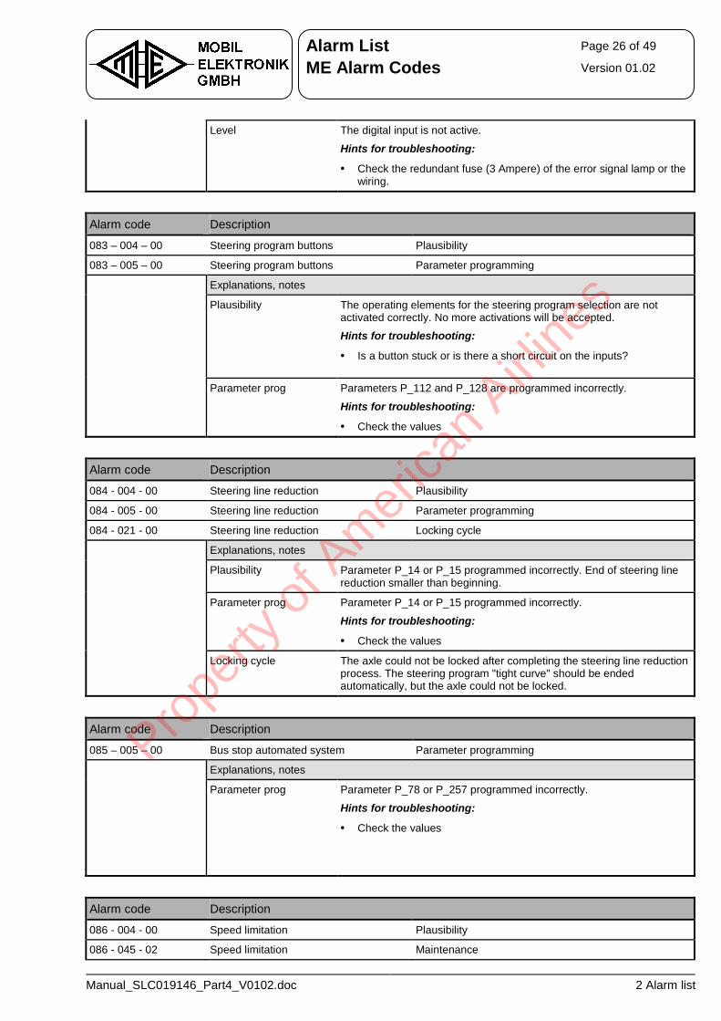
Alarm List Page 26 of 49
ME Alarm Codes Version 01.02
Manual_SLC019146_Part4_V0102.doc 2 Alarm list
Level The digital input is not active.
Hints for troubleshooting:
• Check the redundant fuse (3 Ampere) of the error signal lamp or the wiring.
Alarm code Description
083 – 004 – 00 Steering program buttons Plausibility
083 – 005 – 00 Steering program buttons Parameter programming
Explanations, notes
Plausibility The operating elements for the steering program selection are not activated correctly. No more activations will be accepted.
Hints for troubleshooting:
• Is a button stuck or is there a short circuit on the inputs?
Parameter prog Parameters P_112 and P_128 are programmed incorrectly.
Hints for troubleshooting:
• Check the values
Alarm code Description
084 - 004 - 00 Steering line reduction Plausibility
084 - 005 - 00 Steering line reduction Parameter programming
084 - 021 - 00 Steering line reduction Locking cycle
Explanations, notes
Plausibility Parameter P_14 or P_15 programmed incorrectly. End of steering line reduction smaller than beginning.
Parameter prog Parameter P_14 or P_15 programmed incorrectly.
Hints for troubleshooting:
• Check the values
Locking cycle The axle could not be locked after completing the steering line reduction process. The steering program "tight curve" should be ended automatically, but the axle could not be locked.
Alarm code Description
085 – 005 – 00 Bus stop automated system Parameter programming
Explanations, notes
Parameter prog Parameter P_78 or P_257 programmed incorrectly.
Hints for troubleshooting:
• Check the values
Alarm code Description
086 - 004 - 00 Speed limitation Plausibility
086 - 045 - 02 Speed limitation Maintenance
Prope
rty o
f Am
erica
n Airli
nes
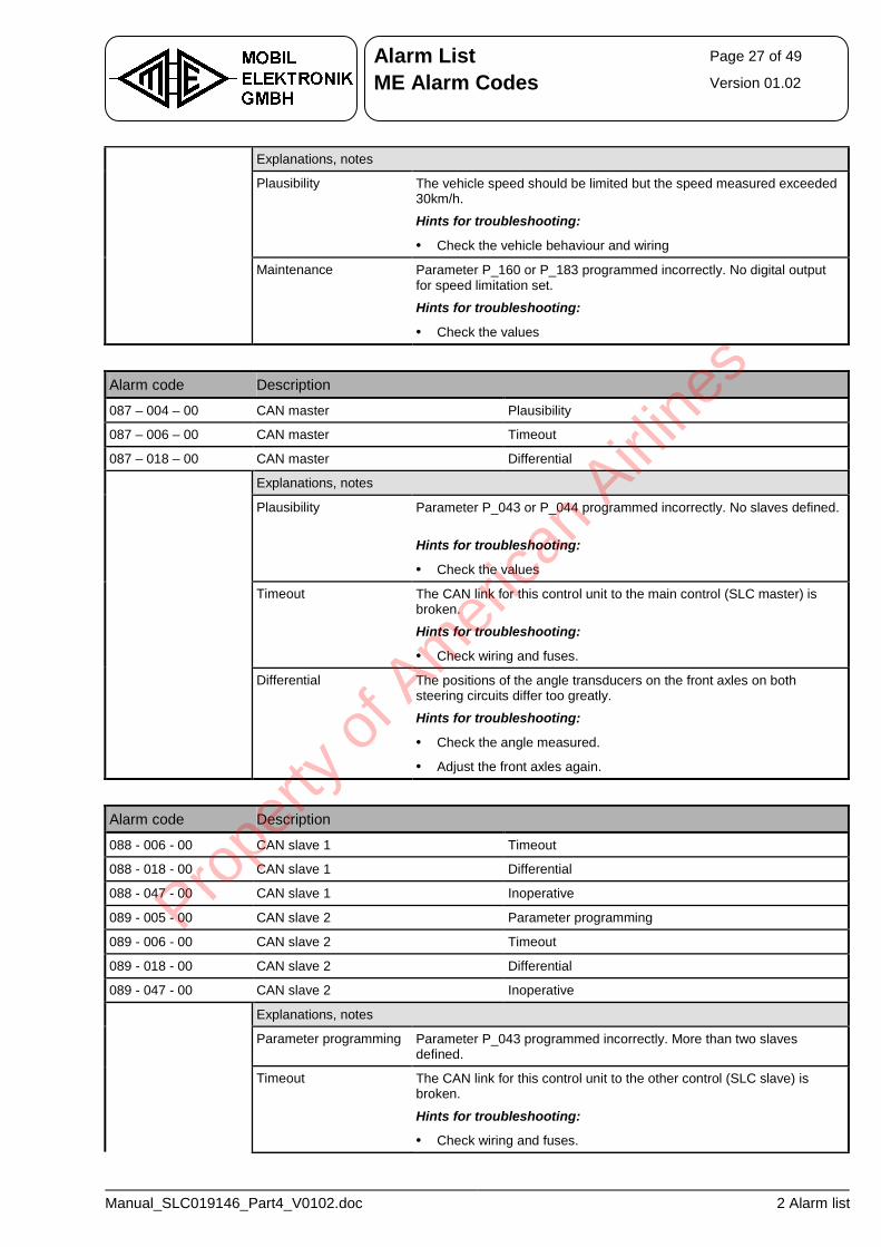
Alarm List Page 27 of 49
ME Alarm Codes Version 01.02
Manual_SLC019146_Part4_V0102.doc 2 Alarm list
Explanations, notes
Plausibility The vehicle speed should be limited but the speed measured exceeded 30km/h.
Hints for troubleshooting:
• Check the vehicle behaviour and wiring
Maintenance Parameter P_160 or P_183 programmed incorrectly. No digital output for speed limitation set.
Hints for troubleshooting:
• Check the values
Alarm code Description
087 – 004 – 00 CAN master Plausibility
087 – 006 – 00 CAN master Timeout
087 – 018 – 00 CAN master Differential
Explanations, notes
Plausibility Parameter P_043 or P_044 programmed incorrectly. No slaves defined.
Hints for troubleshooting:
• Check the values
Timeout The CAN link for this control unit to the main control (SLC master) is broken.
Hints for troubleshooting:
• Check wiring and fuses.
Differential The positions of the angle transducers on the front axles on both steering circuits differ too greatly.
Hints for troubleshooting:
• Check the angle measured.
• Adjust the front axles again.
Alarm code Description
088 - 006 - 00 CAN slave 1 Timeout
088 - 018 - 00 CAN slave 1 Differential
088 - 047 - 00 CAN slave 1 Inoperative
089 - 005 - 00 CAN slave 2 Parameter programming
089 - 006 - 00 CAN slave 2 Timeout
089 - 018 - 00 CAN slave 2 Differential
089 - 047 - 00 CAN slave 2 Inoperative
Explanations, notes
Parameter programming Parameter P_043 programmed incorrectly. More than two slaves defined.
Timeout The CAN link for this control unit to the other control (SLC slave) is broken.
Hints for troubleshooting:
• Check wiring and fuses.
Prope
rty o
f Am
erica
n Airli
nes
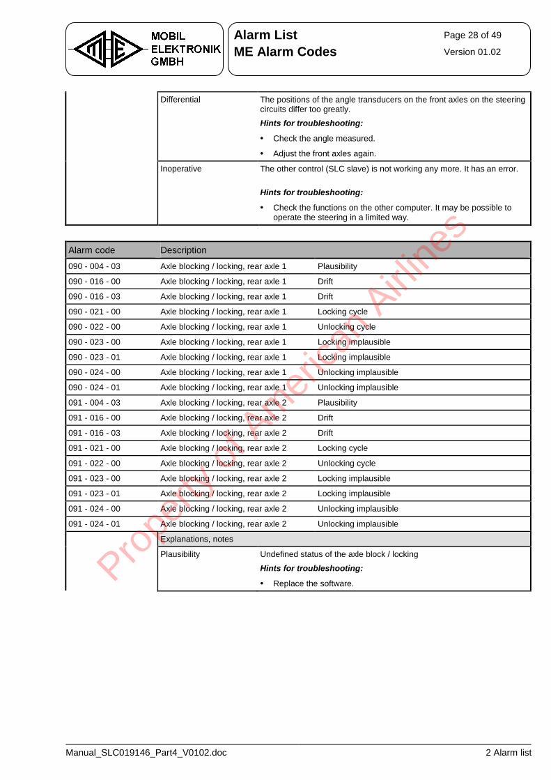
Alarm List Page 28 of 49
ME Alarm Codes Version 01.02
Manual_SLC019146_Part4_V0102.doc 2 Alarm list
Differential The positions of the angle transducers on the front axles on the steering circuits differ too greatly.
Hints for troubleshooting:
• Check the angle measured.
• Adjust the front axles again.
Inoperative The other control (SLC slave) is not working any more. It has an error.
Hints for troubleshooting:
• Check the functions on the other computer. It may be possible to operate the steering in a limited way.
Alarm code Description
090 - 004 - 03 Axle blocking / locking, rear axle 1 Plausibility
090 - 016 - 00 Axle blocking / locking, rear axle 1 Drift
090 - 016 - 03 Axle blocking / locking, rear axle 1 Drift
090 - 021 - 00 Axle blocking / locking, rear axle 1 Locking cycle
090 - 022 - 00 Axle blocking / locking, rear axle 1 Unlocking cycle
090 - 023 - 00 Axle blocking / locking, rear axle 1 Locking implausible
090 - 023 - 01 Axle blocking / locking, rear axle 1 Locking implausible
090 - 024 - 00 Axle blocking / locking, rear axle 1 Unlocking implausible
090 - 024 - 01 Axle blocking / locking, rear axle 1 Unlocking implausible
091 - 004 - 03 Axle blocking / locking, rear axle 2 Plausibility
091 - 016 - 00 Axle blocking / locking, rear axle 2 Drift
091 - 016 - 03 Axle blocking / locking, rear axle 2 Drift
091 - 021 - 00 Axle blocking / locking, rear axle 2 Locking cycle
091 - 022 - 00 Axle blocking / locking, rear axle 2 Unlocking cycle
091 - 023 - 00 Axle blocking / locking, rear axle 2 Locking implausible
091 - 023 - 01 Axle blocking / locking, rear axle 2 Locking implausible
091 - 024 - 00 Axle blocking / locking, rear axle 2 Unlocking implausible
091 - 024 - 01 Axle blocking / locking, rear axle 2 Unlocking implausible
Explanations, notes
Plausibility Undefined status of the axle block / locking
Hints for troubleshooting:
• Replace the software. Prope
rty o
f Am
erica
n Airli
nes
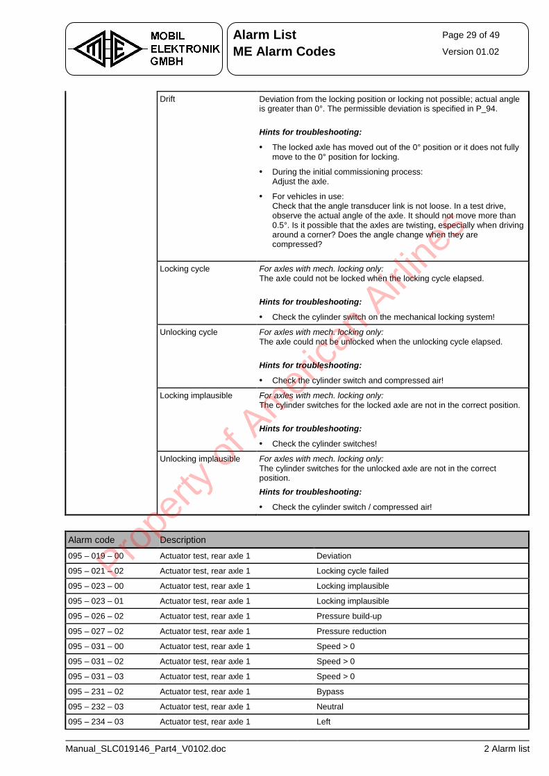
Alarm List Page 29 of 49
ME Alarm Codes Version 01.02
Manual_SLC019146_Part4_V0102.doc 2 Alarm list
Drift Deviation from the locking position or locking not possible; actual angle is greater than 0°. The permissible deviation is specified in P_94.
Hints for troubleshooting:
• The locked axle has moved out of the 0° position or it does not fully move to the 0° position for locking.
• During the initial commissioning process: Adjust the axle.
• For vehicles in use: Check that the angle transducer link is not loose. In a test drive, observe the actual angle of the axle. It should not move more than 0.5°. Is it possible that the axles are twisting, especially when driving around a corner? Does the angle change when they are compressed?
Locking cycle For axles with mech. locking only: The axle could not be locked when the locking cycle elapsed.
Hints for troubleshooting:
• Check the cylinder switch on the mechanical locking system!
Unlocking cycle For axles with mech. locking only: The axle could not be unlocked when the unlocking cycle elapsed.
Hints for troubleshooting:
• Check the cylinder switch and compressed air!
Locking implausible For axles with mech. locking only: The cylinder switches for the locked axle are not in the correct position.
Hints for troubleshooting:
• Check the cylinder switches!
Unlocking implausible For axles with mech. locking only: The cylinder switches for the unlocked axle are not in the correct position.
Hints for troubleshooting:
• Check the cylinder switch / compressed air!
Alarm code Description
095 – 019 – 00 Actuator test, rear axle 1 Deviation
095 – 021 – 02 Actuator test, rear axle 1 Locking cycle failed
095 – 023 – 00 Actuator test, rear axle 1 Locking implausible
095 – 023 – 01 Actuator test, rear axle 1 Locking implausible
095 – 026 – 02 Actuator test, rear axle 1 Pressure build-up
095 – 027 – 02 Actuator test, rear axle 1 Pressure reduction
095 – 031 – 00 Actuator test, rear axle 1 Speed > 0
095 – 031 – 02 Actuator test, rear axle 1 Speed > 0
095 – 031 – 03 Actuator test, rear axle 1 Speed > 0
095 – 231 – 02 Actuator test, rear axle 1 Bypass
095 – 232 – 03 Actuator test, rear axle 1 Neutral
095 – 234 – 03 Actuator test, rear axle 1 Left
Prope
rty o
f Am
erica
n Airli
nes
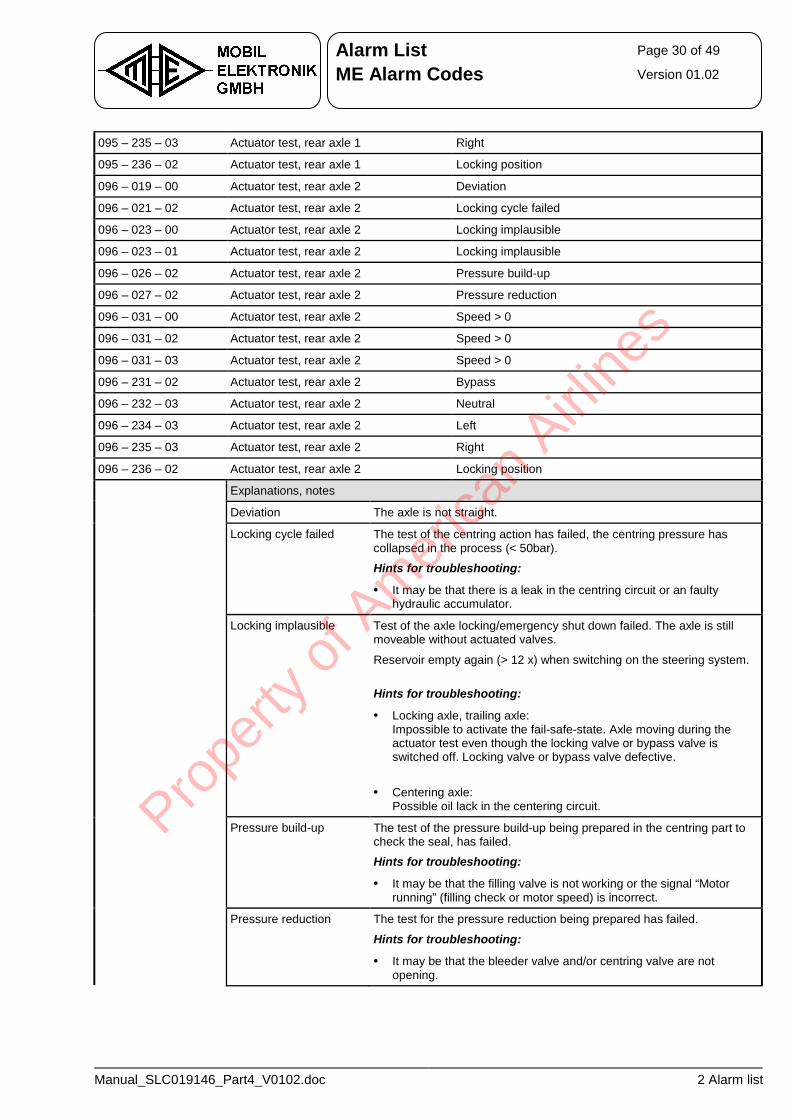
Alarm List Page 30 of 49
ME Alarm Codes Version 01.02
Manual_SLC019146_Part4_V0102.doc 2 Alarm list
095 – 235 – 03 Actuator test, rear axle 1 Right
095 – 236 – 02 Actuator test, rear axle 1 Locking position
096 – 019 – 00 Actuator test, rear axle 2 Deviation
096 – 021 – 02 Actuator test, rear axle 2 Locking cycle failed
096 – 023 – 00 Actuator test, rear axle 2 Locking implausible
096 – 023 – 01 Actuator test, rear axle 2 Locking implausible
096 – 026 – 02 Actuator test, rear axle 2 Pressure build-up
096 – 027 – 02 Actuator test, rear axle 2 Pressure reduction
096 – 031 – 00 Actuator test, rear axle 2 Speed > 0
096 – 031 – 02 Actuator test, rear axle 2 Speed > 0
096 – 031 – 03 Actuator test, rear axle 2 Speed > 0
096 – 231 – 02 Actuator test, rear axle 2 Bypass
096 – 232 – 03 Actuator test, rear axle 2 Neutral
096 – 234 – 03 Actuator test, rear axle 2 Left
096 – 235 – 03 Actuator test, rear axle 2 Right
096 – 236 – 02 Actuator test, rear axle 2 Locking position
Explanations, notes
Deviation The axle is not straight.
Locking cycle failed The test of the centring action has failed, the centring pressure has collapsed in the process (< 50bar).
Hints for troubleshooting:
• It may be that there is a leak in the centring circuit or an faulty hydraulic accumulator.
Locking implausible Test of the axle locking/emergency shut down failed. The axle is still moveable without actuated valves.
Reservoir empty again (> 12 x) when switching on the steering system.
Hints for troubleshooting:
• Locking axle, trailing axle: Impossible to activate the fail-safe-state. Axle moving during the actuator test even though the locking valve or bypass valve is switched off. Locking valve or bypass valve defective.
• Centering axle: Possible oil lack in the centering circuit.
Pressure build-up The test of the pressure build-up being prepared in the centring part to check the seal, has failed.
Hints for troubleshooting:
• It may be that the filling valve is not working or the signal “Motor running” (filling check or motor speed) is incorrect.
Pressure reduction The test for the pressure reduction being prepared has failed.
Hints for troubleshooting:
• It may be that the bleeder valve and/or centring valve are not opening.
Prope
rty o
f Am
erica
n Airli
nes
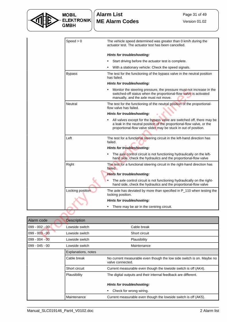
Alarm List Page 31 of 49
ME Alarm Codes Version 01.02
Manual_SLC019146_Part4_V0102.doc 2 Alarm list
Speed > 0 The vehicle speed determined was greater than 0 km/h during the actuator test. The actuator test has been cancelled.
Hints for troubleshooting:
• Start driving before the actuator test is complete.
• With a stationary vehicle: Check the speed signals.
Bypass The test for the functioning of the bypass valve in the neutral position has failed.
Hints for troubleshooting:
• Monitor the steering pressure, the pressure must not increase in the switched-off status when the proportional-flow valve is activated manually, and the axle must not move.
Neutral The test for the functioning of the neutral position of the proportional-flow valve has failed.
Hints for troubleshooting:
• All valves except for the bypass valve are switched off, there may be a leak in the neutral position of the proportional-flow valve, or the proportional-flow valve slider may be stuck in out of position.
Left The test for a functional steering circuit in the left-hand direction has failed.
Hints for troubleshooting:
• The axle control circuit is not functioning hydraulically on the left-hand side, check the hydraulics and the proportional-flow valve
Right The test for a functional steering circuit in the right-hand direction has failed.
Hints for troubleshooting:
• The axle control circuit is not functioning hydraulically on the right-hand side, check the hydraulics and the proportional-flow valve
Locking position The axle has deviated by more than specified in P_110 when testing the locking position.
Hints for troubleshooting:
• There may be air in the centring circuit.
Alarm code Description
099 - 002 - 00 Lowside switch Cable break
099 - 003 - 00 Lowside switch Short circuit
099 - 004 - 00 Lowside switch Plausibility
099 - 045 - 00 Lowside switch Maintenance
Explanations, notes
Cable break No current measurable even though the low side switch is on. Maybe no valve connected.
Short circuit Current measurable even though the lowside switch is off (AK4).
Plausibility The digital outputs and their internal feedback are different.
Hints for troubleshooting:
• Check for wrong wiring.
Maintenance Current measurable even though the lowside switch is off (AK5).
Prope
rty o
f Am
erica
n Airli
nes
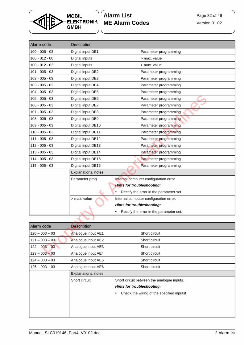
Alarm List Page 32 of 49
ME Alarm Codes Version 01.02
Manual_SLC019146_Part4_V0102.doc 2 Alarm list
Alarm code Description
100 - 005 - 03 Digital input DE1 Parameter programming
100 - 012 - 00 Digital inputs > max. value
100 - 012 - 03 Digital inputs > max. value
101 - 005 - 03 Digital input DE2 Parameter programming
102 - 005 - 03 Digital input DE3 Parameter programming
103 - 005 - 03 Digital input DE4 Parameter programming
104 - 005 - 03 Digital input DE5 Parameter programming
105 - 005 - 03 Digital input DE6 Parameter programming
106 - 005 - 03 Digital input DE7 Parameter programming
107 - 005 - 03 Digital input DE8 Parameter programming
108 - 005 - 03 Digital input DE9 Parameter programming
109 - 005 - 03 Digital input DE10 Parameter programming
110 - 005 - 03 Digital input DE11 Parameter programming
111 - 005 - 03 Digital input DE12 Parameter programming
112 - 005 - 03 Digital input DE13 Parameter programming
113 - 005 - 03 Digital input DE14 Parameter programming
114 - 005 - 03 Digital input DE15 Parameter programming
115 - 005 - 03 Digital input DE16 Parameter programming
Explanations, notes
Parameter prog Internal computer configuration error.
Hints for troubleshooting:
• Rectify the error in the parameter set.
> max. value Internal computer configuration error.
Hints for troubleshooting:
• Rectify the error in the parameter set.
Alarm code Description
120 – 003 – 03 Analogue input AE1 Short circuit
121 – 003 – 03 Analogue input AE2 Short circuit
122 – 003 – 03 Analogue input AE3 Short circuit
123 – 003 – 03 Analogue input AE4 Short circuit
124 – 003 – 03 Analogue input AE5 Short circuit
125 – 003 – 03 Analogue input AE6 Short circuit
Explanations, notes
Short circuit Short circuit between the analogue inputs.
Hints for troubleshooting:
• Check the wiring of the specified inputs!
Prope
rty o
f Am
erica
n Airli
nes
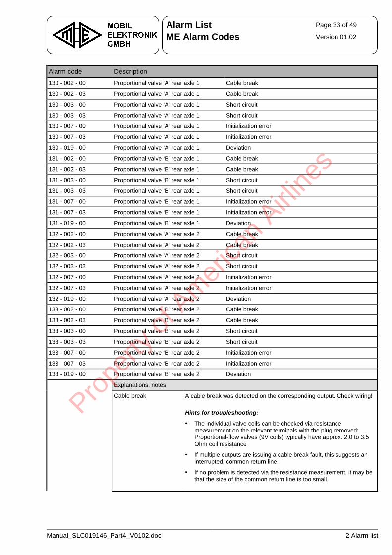
Alarm List Page 33 of 49
ME Alarm Codes Version 01.02
Manual_SLC019146_Part4_V0102.doc 2 Alarm list
Alarm code Description
130 - 002 - 00 Proportional valve ‘A’ rear axle 1 Cable break
130 - 002 - 03 Proportional valve ‘A’ rear axle 1 Cable break
130 - 003 - 00 Proportional valve ‘A’ rear axle 1 Short circuit
130 - 003 - 03 Proportional valve ‘A’ rear axle 1 Short circuit
130 - 007 - 00 Proportional valve ‘A’ rear axle 1 Initialization error
130 - 007 - 03 Proportional valve ‘A’ rear axle 1 Initialization error
130 - 019 - 00 Proportional valve ‘A’ rear axle 1 Deviation
131 - 002 - 00 Proportional valve ‘B’ rear axle 1 Cable break
131 - 002 - 03 Proportional valve ‘B’ rear axle 1 Cable break
131 - 003 - 00 Proportional valve ‘B’ rear axle 1 Short circuit
131 - 003 - 03 Proportional valve ‘B’ rear axle 1 Short circuit
131 - 007 - 00 Proportional valve ‘B’ rear axle 1 Initialization error
131 - 007 - 03 Proportional valve ‘B’ rear axle 1 Initialization error
131 - 019 - 00 Proportional valve ‘B’ rear axle 1 Deviation
132 - 002 - 00 Proportional valve ‘A’ rear axle 2 Cable break
132 - 002 - 03 Proportional valve ‘A’ rear axle 2 Cable break
132 - 003 - 00 Proportional valve ‘A’ rear axle 2 Short circuit
132 - 003 - 03 Proportional valve ‘A’ rear axle 2 Short circuit
132 - 007 - 00 Proportional valve ‘A’ rear axle 2 Initialization error
132 - 007 - 03 Proportional valve ‘A’ rear axle 2 Initialization error
132 - 019 - 00 Proportional valve ‘A’ rear axle 2 Deviation
133 - 002 - 00 Proportional valve ‘B’ rear axle 2 Cable break
133 - 002 - 03 Proportional valve ‘B’ rear axle 2 Cable break
133 - 003 - 00 Proportional valve ‘B’ rear axle 2 Short circuit
133 - 003 - 03 Proportional valve ‘B’ rear axle 2 Short circuit
133 - 007 - 00 Proportional valve ‘B’ rear axle 2 Initialization error
133 - 007 - 03 Proportional valve ‘B’ rear axle 2 Initialization error
133 - 019 - 00 Proportional valve ‘B’ rear axle 2 Deviation
Explanations, notes
Cable break A cable break was detected on the corresponding output. Check wiring!
Hints for troubleshooting:
• The individual valve coils can be checked via resistance measurement on the relevant terminals with the plug removed: Proportional-flow valves (9V coils) typically have approx. 2.0 to 3.5 Ohm coil resistance
• If multiple outputs are issuing a cable break fault, this suggests an interrupted, common return line.
• If no problem is detected via the resistance measurement, it may be that the size of the common return line is too small.
Prope
rty o
f Am
erica
n Airli
nes
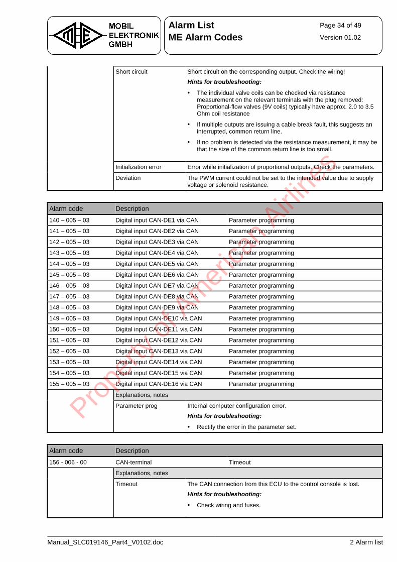
Alarm List Page 34 of 49
ME Alarm Codes Version 01.02
Manual_SLC019146_Part4_V0102.doc 2 Alarm list
Short circuit Short circuit on the corresponding output. Check the wiring!
Hints for troubleshooting:
• The individual valve coils can be checked via resistance measurement on the relevant terminals with the plug removed: Proportional-flow valves (9V coils) typically have approx. 2.0 to 3.5 Ohm coil resistance
• If multiple outputs are issuing a cable break fault, this suggests an interrupted, common return line.
• If no problem is detected via the resistance measurement, it may be that the size of the common return line is too small.
Initialization error Error while initialization of proportional outputs. Check the parameters.
Deviation The PWM current could not be set to the intended value due to supply voltage or solenoid resistance.
Alarm code Description
140 – 005 – 03 Digital input CAN-DE1 via CAN Parameter programming
141 – 005 – 03 Digital input CAN-DE2 via CAN Parameter programming
142 – 005 – 03 Digital input CAN-DE3 via CAN Parameter programming
143 – 005 – 03 Digital input CAN-DE4 via CAN Parameter programming
144 – 005 – 03 Digital input CAN-DE5 via CAN Parameter programming
145 – 005 – 03 Digital input CAN-DE6 via CAN Parameter programming
146 – 005 – 03 Digital input CAN-DE7 via CAN Parameter programming
147 – 005 – 03 Digital input CAN-DE8 via CAN Parameter programming
148 – 005 – 03 Digital input CAN-DE9 via CAN Parameter programming
149 – 005 – 03 Digital input CAN-DE10 via CAN Parameter programming
150 – 005 – 03 Digital input CAN-DE11 via CAN Parameter programming
151 – 005 – 03 Digital input CAN-DE12 via CAN Parameter programming
152 – 005 – 03 Digital input CAN-DE13 via CAN Parameter programming
153 – 005 – 03 Digital input CAN-DE14 via CAN Parameter programming
154 – 005 – 03 Digital input CAN-DE15 via CAN Parameter programming
155 – 005 – 03 Digital input CAN-DE16 via CAN Parameter programming
Explanations, notes
Parameter prog Internal computer configuration error.
Hints for troubleshooting:
• Rectify the error in the parameter set.
Alarm code Description
156 - 006 - 00 CAN-terminal Timeout
Explanations, notes
Timeout The CAN connection from this ECU to the control console is lost.
Hints for troubleshooting:
• Check wiring and fuses.
Prope
rty o
f Am
erica
n Airli
nes
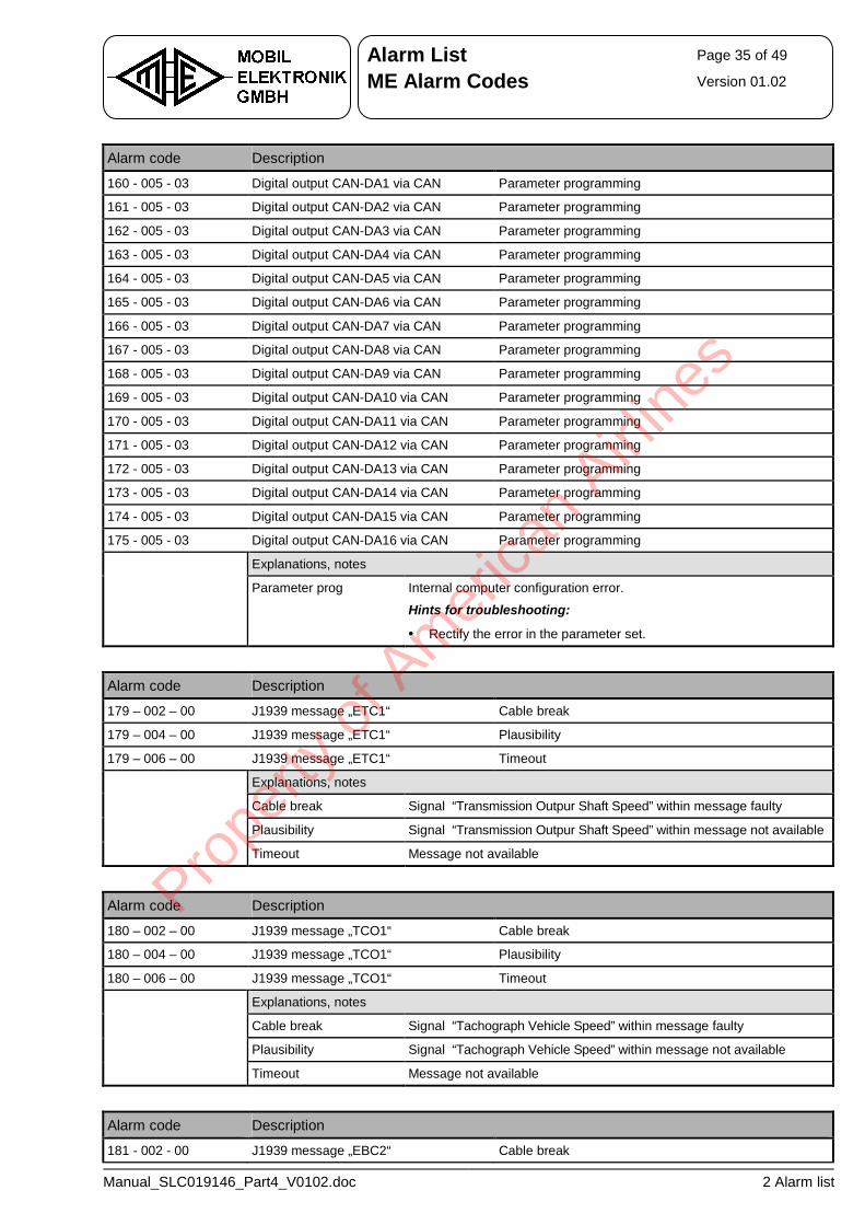
Alarm List Page 35 of 49
ME Alarm Codes Version 01.02
Manual_SLC019146_Part4_V0102.doc 2 Alarm list
Alarm code Description
160 - 005 - 03 Digital output CAN-DA1 via CAN Parameter programming
161 - 005 - 03 Digital output CAN-DA2 via CAN Parameter programming
162 - 005 - 03 Digital output CAN-DA3 via CAN Parameter programming
163 - 005 - 03 Digital output CAN-DA4 via CAN Parameter programming
164 - 005 - 03 Digital output CAN-DA5 via CAN Parameter programming
165 - 005 - 03 Digital output CAN-DA6 via CAN Parameter programming
166 - 005 - 03 Digital output CAN-DA7 via CAN Parameter programming
167 - 005 - 03 Digital output CAN-DA8 via CAN Parameter programming
168 - 005 - 03 Digital output CAN-DA9 via CAN Parameter programming
169 - 005 - 03 Digital output CAN-DA10 via CAN Parameter programming
170 - 005 - 03 Digital output CAN-DA11 via CAN Parameter programming
171 - 005 - 03 Digital output CAN-DA12 via CAN Parameter programming
172 - 005 - 03 Digital output CAN-DA13 via CAN Parameter programming
173 - 005 - 03 Digital output CAN-DA14 via CAN Parameter programming
174 - 005 - 03 Digital output CAN-DA15 via CAN Parameter programming
175 - 005 - 03 Digital output CAN-DA16 via CAN Parameter programming
Explanations, notes
Parameter prog Internal computer configuration error.
Hints for troubleshooting:
• Rectify the error in the parameter set.
Alarm code Description
179 – 002 – 00 J1939 message „ETC1“ Cable break
179 – 004 – 00 J1939 message „ETC1“ Plausibility
179 – 006 – 00 J1939 message „ETC1“ Timeout
Explanations, notes
Cable break Signal “Transmission Outpur Shaft Speed” within message faulty
Plausibility Signal “Transmission Outpur Shaft Speed” within message not available
Timeout Message not available
Alarm code Description
180 – 002 – 00 J1939 message „TCO1“ Cable break
180 – 004 – 00 J1939 message „TCO1“ Plausibility
180 – 006 – 00 J1939 message „TCO1“ Timeout
Explanations, notes
Cable break Signal “Tachograph Vehicle Speed” within message faulty
Plausibility Signal “Tachograph Vehicle Speed” within message not available
Timeout Message not available
Alarm code Description
181 - 002 - 00 J1939 message „EBC2“ Cable break
Prope
rty o
f Am
erica
n Airli
nes
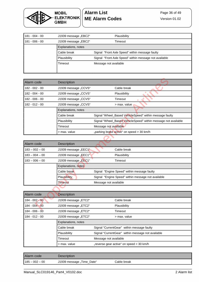
Alarm List Page 36 of 49
ME Alarm Codes Version 01.02
Manual_SLC019146_Part4_V0102.doc 2 Alarm list
181 - 004 - 00 J1939 message „EBC2“ Plausibility
181 - 006 - 00 J1939 message „EBC2“ Timeout
Explanations, notes
Cable break Signal “Front Axle Speed” within message faulty
Plausibility Signal “Front Axle Speed” within message not available
Timeout Message not available
Alarm code Description
182 - 002 - 00 J1939 message „CCVS“ Cable break
182 - 004 - 00 J1939 message „CCVS“ Plausibility
182 - 006 - 00 J1939 message „CCVS“ Timeout
182 - 012 - 00 J1939 message „CCVS“ > max. value
Explanations, notes
Cable break Signal “Wheel_Based VehicleSpeed” within message faulty
Plausibility Signal “Wheel_Based VehicleSpeed” within message not available
Timeout Message not available
> max. value „parking brake active“ on speed > 30 km/h
Alarm code Description
183 – 002 – 00 J1939 message „EEC1“ Cable break
183 – 004 – 00 J1939 message „EEC1“ Plausibility
183 – 006 – 00 J1939 message „EEC1“ Timeout
Explanations, notes
Cable break Signal “Engine Speed” within message faulty
Plausibility Signal “Engine Speed” within message not available
Timeout Message not available
Alarm code Description
184 - 002 - 00 J1939 message „ETC2“ Cable break
184 - 004 - 00 J1939 message „ETC2“ Plausibility
184 - 006 - 00 J1939 message „ETC2“ Timeout
184 - 012 - 00 J1939 message „ETC2“ > max. value
Explanations, notes
Cable break Signal “CurrentGear” within message faulty
Plausibility Signal “CurrentGear” within message not available
Timeout Message not available
> max. value „reverse gear active“ on speed > 30 km/h
Alarm code Description
185 – 002 – 00 J1939 message „Time_Date“ Cable break
Prope
rty o
f Am
erica
n Airli
nes
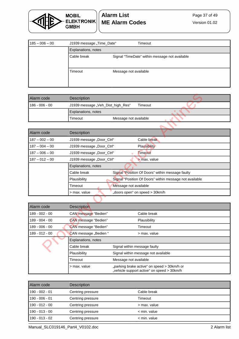
Alarm List Page 37 of 49
ME Alarm Codes Version 01.02
Manual_SLC019146_Part4_V0102.doc 2 Alarm list
185 – 006 – 00 J1939 message „Time_Date“ Timeout
Explanations, notes
Cable break Signal “TimeDate” within message not available
Timeout Message not available
Alarm code Description
186 - 006 - 00 J1939 message „Veh_Dist_high_Res“ Timeout
Explanations, notes
Timeout Message not available
Alarm code Description
187 – 002 – 00 J1939 message „Door_Ctrl“ Cable break
187 – 004 – 00 J1939 message „Door_Ctrl“ Plausibility
187 – 006 – 00 J1939 message „Door_Ctrl“ Timeout
187 – 012 – 00 J1939 message „Door_Ctrl“ > max. value
Explanations, notes
Cable break Signal “Position Of Doors” within message faulty
Plausibility Signal “Position Of Doors” within message not available
Timeout Message not available
> max. value „doors open“ on speed > 30km/h
Alarm code Description
189 - 002 - 00 CAN message “Bedien” Cable break
189 - 004 - 00 CAN message “Bedien” Plausibility
189 - 006 - 00 CAN message “Bedien” Timeout
189 - 012 - 00 CAN message „Bedien “ > max. value
Explanations, notes
Cable break Signal within message faulty
Plausibility Signal within message not available
Timeout Message not available
> max. value „parking brake active“ on speed > 30km/h or „vehicle support active“ on speed > 30km/h
Alarm code Description
190 - 002 - 01 Centring pressure Cable break
190 - 006 - 01 Centring pressure Timeout
190 - 012 - 00 Centring pressure > max. value
190 - 013 - 00 Centring pressure < min. value
190 - 013 - 02 Centring pressure < min. value
Prope
rty o
f Am
erica
n Airli
nes
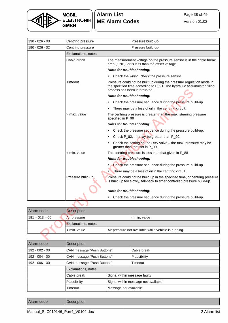
Alarm List Page 38 of 49
ME Alarm Codes Version 01.02
Manual_SLC019146_Part4_V0102.doc 2 Alarm list
190 - 026 - 00 Centring pressure Pressure build-up
190 - 026 - 02 Centring pressure Pressure build-up
Explanations, notes
Cable break The measurement voltage on the pressure sensor is in the cable break area (GND), or is less than the offset voltage.
Hints for troubleshooting:
• Check the wiring, check the pressure sensor.
Timeout Pressure could not be built up during the pressure regulation mode in the specified time according to P_91. The hydraulic accumulator filling process has been interrupted.
Hints for troubleshooting:
• Check the pressure sequence during the pressure build-up.
• There may be a loss of oil in the centring circuit.
> max. value The centring pressure is greater than the max. steering pressure specified in P_90
Hints for troubleshooting:
• Check the pressure sequence during the pressure build-up.
• Check P_82. – it may be greater than P_90.
• Check the setting on the DBV valve – the max. pressure may be greater than that set in P_90.
< min. value The centring pressure is less than that given in P_88
Hints for troubleshooting:
• Check the pressure sequence during the pressure build-up.
• There may be a loss of oil in the centring circuit.
Pressure build-up Pressure could not be build up in the specified time, or centring pressure is build up too slowly, fall-back to timer controlled pressure build-up.
Hints for troubleshooting:
• Check the pressure sequence during the pressure build-up.
Alarm code Description
191 – 013 – 00 Air pressure < min. value
Explanations, notes
< min. value Air pressure not available while vehicle is running.
Alarm code Description
192 - 002 - 00 CAN message “Push Buttons” Cable break
192 - 004 - 00 CAN message “Push Buttons” Plausibility
192 - 006 - 00 CAN message “Push Buttons” Timeout
Explanations, notes
Cable break Signal within message faulty
Plausibility Signal within message not available
Timeout Message not available
Alarm code Description
Prope
rty o
f Am
erica
n Airli
nes
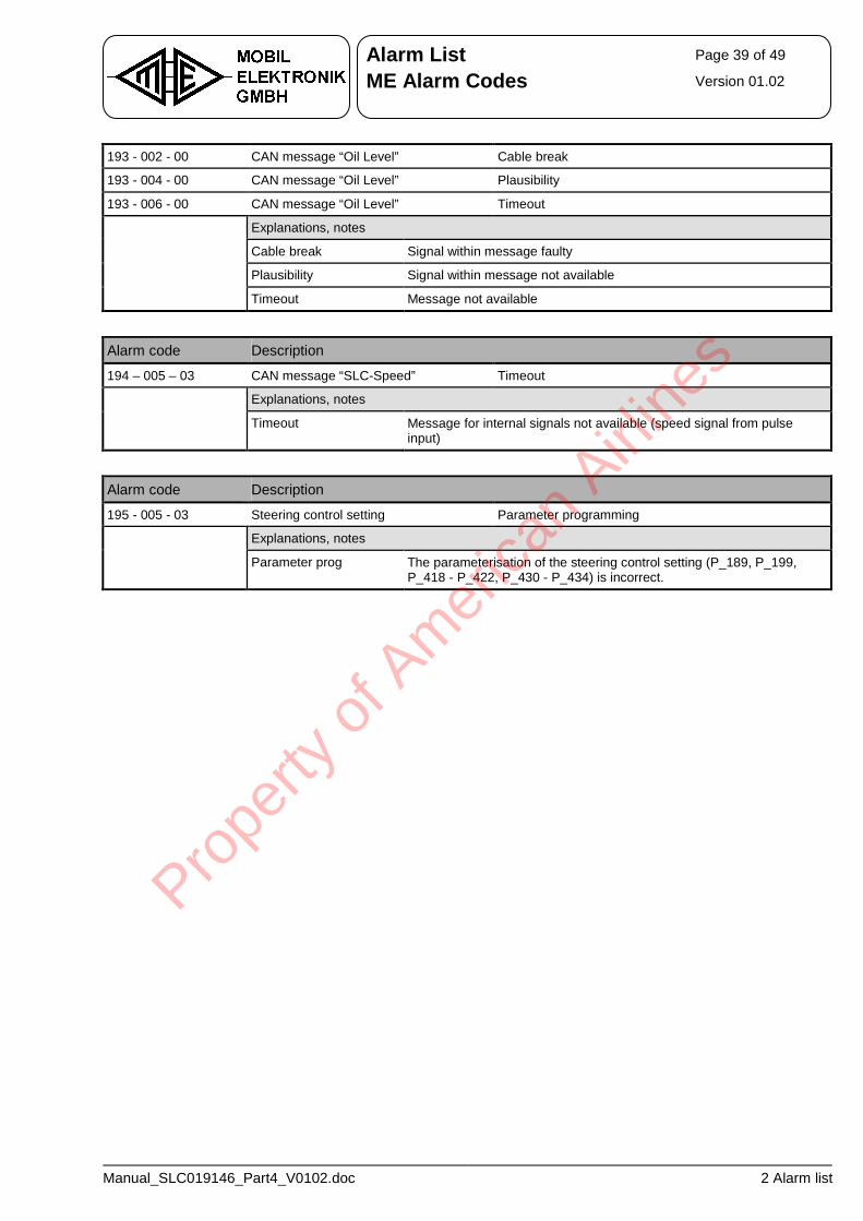
Alarm List Page 39 of 49
ME Alarm Codes Version 01.02
Manual_SLC019146_Part4_V0102.doc 2 Alarm list
193 - 002 - 00 CAN message “Oil Level” Cable break
193 - 004 - 00 CAN message “Oil Level” Plausibility
193 - 006 - 00 CAN message “Oil Level” Timeout
Explanations, notes
Cable break Signal within message faulty
Plausibility Signal within message not available
Timeout Message not available
Alarm code Description
194 – 005 – 03 CAN message “SLC-Speed” Timeout
Explanations, notes
Timeout Message for internal signals not available (speed signal from pulse input)
Alarm code Description
195 - 005 - 03 Steering control setting Parameter programming
Explanations, notes
Parameter prog The parameterisation of the steering control setting (P_189, P_199, P_418 - P_422, P_430 - P_434) is incorrect.
Prope
rty o
f Am
erica
n Airli
nes
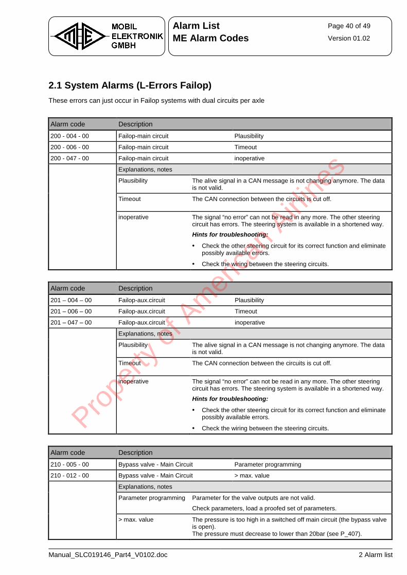
Alarm List Page 40 of 49
ME Alarm Codes Version 01.02
Manual_SLC019146_Part4_V0102.doc 2 Alarm list
2.1 System Alarms (L-Errors Failop) These errors can just occur in Failop systems with dual circuits per axle
Alarm code Description
200 - 004 - 00 Failop-main circuit Plausibility
200 - 006 - 00 Failop-main circuit Timeout
200 - 047 - 00 Failop-main circuit inoperative
Explanations, notes
Plausibility The alive signal in a CAN message is not changing anymore. The data is not valid.
Timeout The CAN connection between the circuits is cut off.
inoperative The signal “no error” can not be read in any more. The other steering circuit has errors. The steering system is available in a shortened way.
Hints for troubleshooting:
• Check the other steering circuit for its correct function and eliminate possibly available errors.
• Check the wiring between the steering circuits.
Alarm code Description
201 – 004 – 00 Failop-aux.circuit Plausibility
201 – 006 – 00 Failop-aux.circuit Timeout
201 – 047 – 00 Failop-aux.circuit inoperative
Explanations, notes
Plausibility The alive signal in a CAN message is not changing anymore. The data is not valid.
Timeout The CAN connection between the circuits is cut off.
inoperative The signal “no error” can not be read in any more. The other steering circuit has errors. The steering system is available in a shortened way.
Hints for troubleshooting:
• Check the other steering circuit for its correct function and eliminate possibly available errors.
• Check the wiring between the steering circuits.
Alarm code Description
210 - 005 - 00 Bypass valve - Main Circuit Parameter programming
210 - 012 - 00 Bypass valve - Main Circuit > max. value
Explanations, notes
Parameter programming Parameter for the valve outputs are not valid.
Check parameters, load a proofed set of parameters. > max. value The pressure is too high in a switched off main circuit (the bypass valve
is open). The pressure must decrease to lower than 20bar (see P_407).
Prope
rty o
f Am
erica
n Airli
nes
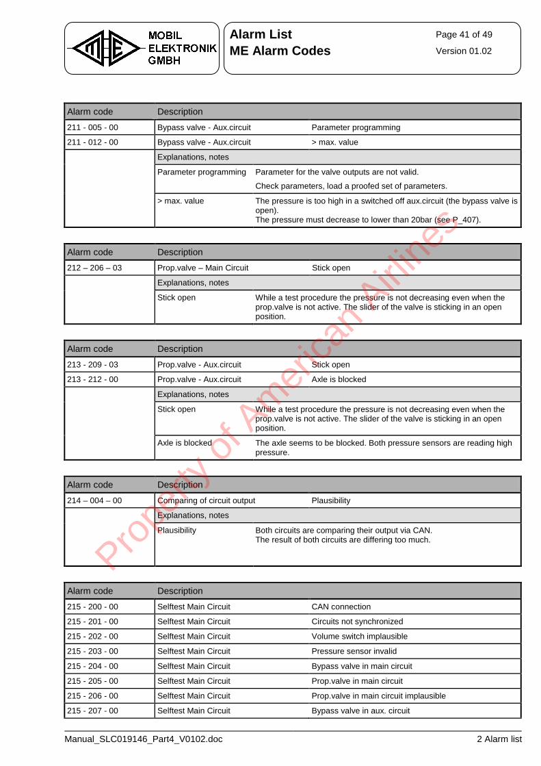
Alarm List Page 41 of 49
ME Alarm Codes Version 01.02
Manual_SLC019146_Part4_V0102.doc 2 Alarm list
Alarm code Description
211 - 005 - 00 Bypass valve - Aux.circuit Parameter programming
211 - 012 - 00 Bypass valve - Aux.circuit > max. value
Explanations, notes
Parameter programming Parameter for the valve outputs are not valid.
Check parameters, load a proofed set of parameters. > max. value The pressure is too high in a switched off aux.circuit (the bypass valve is
open). The pressure must decrease to lower than 20bar (see P_407).
Alarm code Description
212 – 206 – 03 Prop.valve – Main Circuit Stick open
Explanations, notes
Stick open While a test procedure the pressure is not decreasing even when the prop.valve is not active. The slider of the valve is sticking in an open position.
Alarm code Description
213 - 209 - 03 Prop.valve - Aux.circuit Stick open
213 - 212 - 00 Prop.valve - Aux.circuit Axle is blocked
Explanations, notes
Stick open While a test procedure the pressure is not decreasing even when the prop.valve is not active. The slider of the valve is sticking in an open position.
Axle is blocked The axle seems to be blocked. Both pressure sensors are reading high pressure.
Alarm code Description
214 – 004 – 00 Comparing of circuit output Plausibility
Explanations, notes
Plausibility Both circuits are comparing their output via CAN. The result of both circuits are differing too much.
Alarm code Description
215 - 200 - 00 Selftest Main Circuit CAN connection
215 - 201 - 00 Selftest Main Circuit Circuits not synchronized
215 - 202 - 00 Selftest Main Circuit Volume switch implausible
215 - 203 - 00 Selftest Main Circuit Pressure sensor invalid
215 - 204 - 00 Selftest Main Circuit Bypass valve in main circuit
215 - 205 - 00 Selftest Main Circuit Prop.valve in main circuit
215 - 206 - 00 Selftest Main Circuit Prop.valve in main circuit implausible
215 - 207 - 00 Selftest Main Circuit Bypass valve in aux. circuit
Prope
rty o
f Am
erica
n Airli
nes
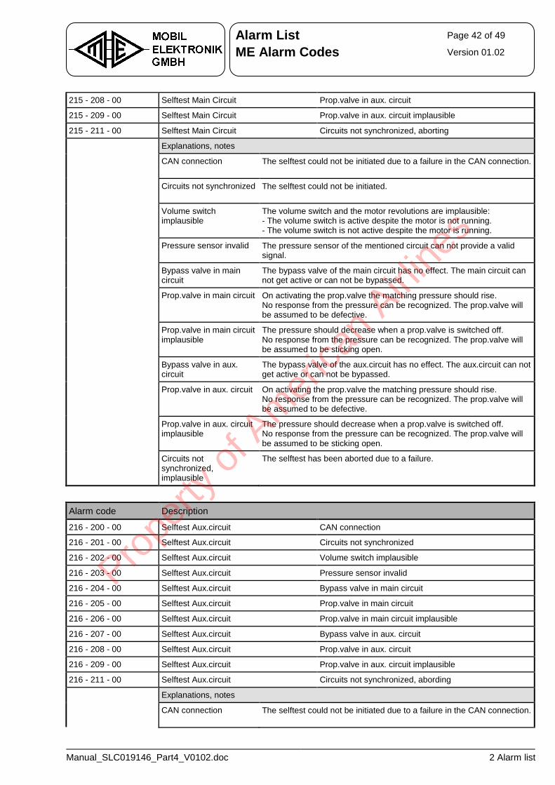
Alarm List Page 42 of 49
ME Alarm Codes Version 01.02
Manual_SLC019146_Part4_V0102.doc 2 Alarm list
215 - 208 - 00 Selftest Main Circuit Prop.valve in aux. circuit
215 - 209 - 00 Selftest Main Circuit Prop.valve in aux. circuit implausible
215 - 211 - 00 Selftest Main Circuit Circuits not synchronized, aborting
Explanations, notes
CAN connection The selftest could not be initiated due to a failure in the CAN connection.
Circuits not synchronized The selftest could not be initiated.
Volume switch implausible
The volume switch and the motor revolutions are implausible: - The volume switch is active despite the motor is not running. - The volume switch is not active despite the motor is running.
Pressure sensor invalid The pressure sensor of the mentioned circuit can not provide a valid signal.
Bypass valve in main circuit
The bypass valve of the main circuit has no effect. The main circuit can not get active or can not be bypassed.
Prop.valve in main circuit On activating the prop.valve the matching pressure should rise. No response from the pressure can be recognized. The prop.valve will be assumed to be defective.
Prop.valve in main circuit implausible
The pressure should decrease when a prop.valve is switched off. No response from the pressure can be recognized. The prop.valve will be assumed to be sticking open.
Bypass valve in aux. circuit
The bypass valve of the aux.circuit has no effect. The aux.circuit can not get active or can not be bypassed.
Prop.valve in aux. circuit On activating the prop.valve the matching pressure should rise. No response from the pressure can be recognized. The prop.valve will be assumed to be defective.
Prop.valve in aux. circuit implausible
The pressure should decrease when a prop.valve is switched off. No response from the pressure can be recognized. The prop.valve will be assumed to be sticking open.
Circuits not synchronized, implausible
The selftest has been aborted due to a failure.
Alarm code Description
216 - 200 - 00 Selftest Aux.circuit CAN connection
216 - 201 - 00 Selftest Aux.circuit Circuits not synchronized
216 - 202 - 00 Selftest Aux.circuit Volume switch implausible
216 - 203 - 00 Selftest Aux.circuit Pressure sensor invalid
216 - 204 - 00 Selftest Aux.circuit Bypass valve in main circuit
216 - 205 - 00 Selftest Aux.circuit Prop.valve in main circuit
216 - 206 - 00 Selftest Aux.circuit Prop.valve in main circuit implausible
216 - 207 - 00 Selftest Aux.circuit Bypass valve in aux. circuit
216 - 208 - 00 Selftest Aux.circuit Prop.valve in aux. circuit
216 - 209 - 00 Selftest Aux.circuit Prop.valve in aux. circuit implausible
216 - 211 - 00 Selftest Aux.circuit Circuits not synchronized, abording
Explanations, notes
CAN connection The selftest could not be initiated due to a failure in the CAN connection.
Prope
rty o
f Am
erica
n Airli
nes
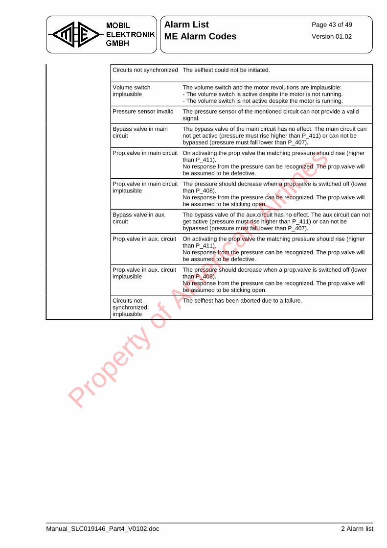
Alarm List Page 43 of 49
ME Alarm Codes Version 01.02
Manual_SLC019146_Part4_V0102.doc 2 Alarm list
Circuits not synchronized The selftest could not be initiated.
Volume switch implausible
The volume switch and the motor revolutions are implausible: - The volume switch is active despite the motor is not running. - The volume switch is not active despite the motor is running.
Pressure sensor invalid The pressure sensor of the mentioned circuit can not provide a valid signal.
Bypass valve in main circuit
The bypass valve of the main circuit has no effect. The main circuit can not get active (pressure must rise higher than P_411) or can not be bypassed (pressure must fall lower than P_407).
Prop.valve in main circuit On activating the prop.valve the matching pressure should rise (higher than P_411). No response from the pressure can be recognized. The prop.valve will be assumed to be defective.
Prop.valve in main circuit implausible
The pressure should decrease when a prop.valve is switched off (lower than P_408). No response from the pressure can be recognized. The prop.valve will be assumed to be sticking open.
Bypass valve in aux. circuit
The bypass valve of the aux.circuit has no effect. The aux.circuit can not get active (pressure must rise higher than P_411) or can not be bypassed (pressure must fall lower than P_407).
Prop.valve in aux. circuit On activating the prop.valve the matching pressure should rise (higher than P_411). No response from the pressure can be recognized. The prop.valve will be assumed to be defective.
Prop.valve in aux. circuit implausible
The pressure should decrease when a prop.valve is switched off (lower than P_408). No response from the pressure can be recognized. The prop.valve will be assumed to be sticking open.
Circuits not synchronized, implausible
The selftest has been aborted due to a failure.
Prope
rty o
f Am
erica
n Airli
nes
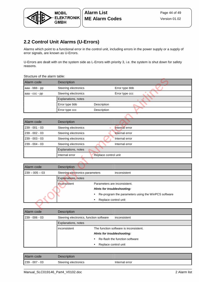
Alarm List Page 44 of 49
ME Alarm Codes Version 01.02
Manual_SLC019146_Part4_V0102.doc 2 Alarm list
2.2 Control Unit Alarms (U-Errors) Alarms which point to a functional error in the control unit, including errors in the power supply or a supply of error signals, are known as U-Errors. U-Errors are dealt with on the system side as L-Errors with priority 3, i.e. the system is shut down for safety reasons. Structure of the alarm table:
Alarm code Description
aaa - bbb - pp Steering electronics Error type bbb
aaa - ccc - pp Steering electronics Error type ccc
Explanations, notes
Error type bbb Description
Error type ccc Description
Alarm code Description
239 - 001 - 03 Steering electronics Internal error
239 - 002 - 03 Steering electronics Internal error
239 - 003 - 03 Steering electronics Internal error
239 - 004 - 03 Steering electronics Internal error
Explanations, notes
Internal error Replace control unit
Alarm code Description
239 – 005 – 03 Steering electronics parameters inconsistent
Explanations, notes
inconsistent Parameters are inconsistent.
Hints for troubleshooting:
• Re-program the parameters using the WinPCS software
• Replace control unit
Alarm code Description
239 - 006 - 03 Steering electronics, function software inconsistent
Explanations, notes
inconsistent The function software is inconsistent.
Hints for troubleshooting:
• Re-flash the function software
• Replace control unit
Alarm code Description
239 - 007 - 03 Steering electronics Internal error
Prope
rty o
f Am
erica
n Airli
nes
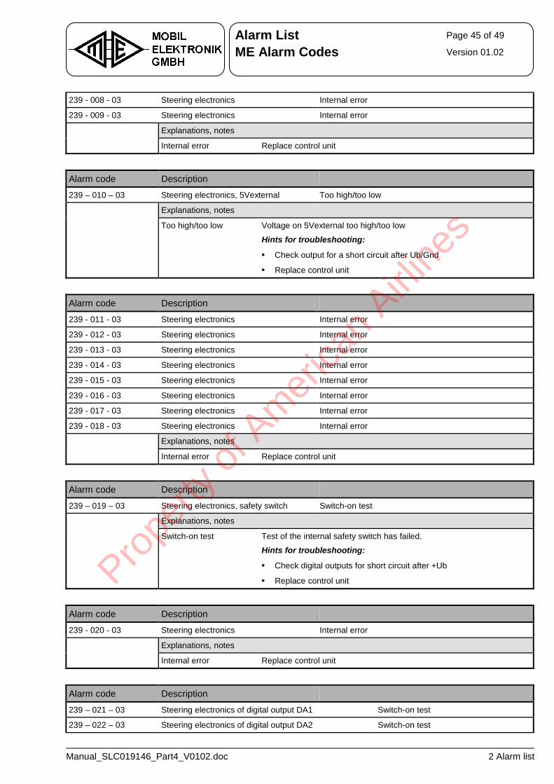
Alarm List Page 45 of 49
ME Alarm Codes Version 01.02
Manual_SLC019146_Part4_V0102.doc 2 Alarm list
239 - 008 - 03 Steering electronics Internal error
239 - 009 - 03 Steering electronics Internal error
Explanations, notes
Internal error Replace control unit
Alarm code Description
239 – 010 – 03 Steering electronics, 5Vexternal Too high/too low
Explanations, notes
Too high/too low Voltage on 5Vexternal too high/too low
Hints for troubleshooting:
• Check output for a short circuit after Ub/Gnd
• Replace control unit
Alarm code Description
239 - 011 - 03 Steering electronics Internal error
239 - 012 - 03 Steering electronics Internal error
239 - 013 - 03 Steering electronics Internal error
239 - 014 - 03 Steering electronics Internal error
239 - 015 - 03 Steering electronics Internal error
239 - 016 - 03 Steering electronics Internal error
239 - 017 - 03 Steering electronics Internal error
239 - 018 - 03 Steering electronics Internal error
Explanations, notes
Internal error Replace control unit
Alarm code Description
239 – 019 – 03 Steering electronics, safety switch Switch-on test
Explanations, notes
Switch-on test Test of the internal safety switch has failed.
Hints for troubleshooting:
• Check digital outputs for short circuit after +Ub
• Replace control unit
Alarm code Description
239 - 020 - 03 Steering electronics Internal error
Explanations, notes
Internal error Replace control unit
Alarm code Description
239 – 021 – 03 Steering electronics of digital output DA1 Switch-on test
239 – 022 – 03 Steering electronics of digital output DA2 Switch-on test
Prope
rty o
f Am
erica
n Airli
nes
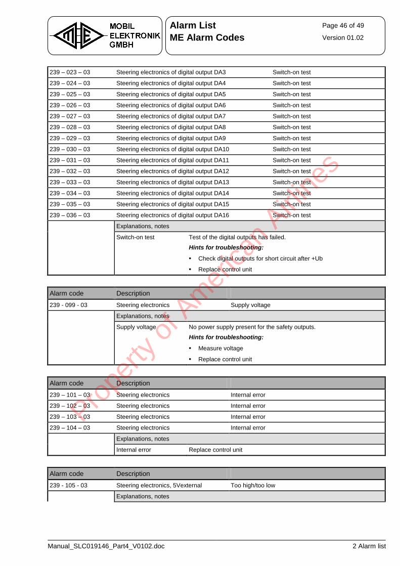
Alarm List Page 46 of 49
ME Alarm Codes Version 01.02
Manual_SLC019146_Part4_V0102.doc 2 Alarm list
239 – 023 – 03 Steering electronics of digital output DA3 Switch-on test
239 – 024 – 03 Steering electronics of digital output DA4 Switch-on test
239 – 025 – 03 Steering electronics of digital output DA5 Switch-on test
239 – 026 – 03 Steering electronics of digital output DA6 Switch-on test
239 – 027 – 03 Steering electronics of digital output DA7 Switch-on test
239 – 028 – 03 Steering electronics of digital output DA8 Switch-on test
239 – 029 – 03 Steering electronics of digital output DA9 Switch-on test
239 – 030 – 03 Steering electronics of digital output DA10 Switch-on test
239 – 031 – 03 Steering electronics of digital output DA11 Switch-on test
239 – 032 – 03 Steering electronics of digital output DA12 Switch-on test
239 – 033 – 03 Steering electronics of digital output DA13 Switch-on test
239 – 034 – 03 Steering electronics of digital output DA14 Switch-on test
239 – 035 – 03 Steering electronics of digital output DA15 Switch-on test
239 – 036 – 03 Steering electronics of digital output DA16 Switch-on test
Explanations, notes
Switch-on test Test of the digital outputs has failed.
Hints for troubleshooting:
• Check digital outputs for short circuit after +Ub
• Replace control unit
Alarm code Description
239 - 099 - 03 Steering electronics Supply voltage
Explanations, notes
Supply voltage No power supply present for the safety outputs.
Hints for troubleshooting:
• Measure voltage
• Replace control unit
Alarm code Description
239 – 101 – 03 Steering electronics Internal error
239 – 102 – 03 Steering electronics Internal error
239 – 103 – 03 Steering electronics Internal error
239 – 104 – 03 Steering electronics Internal error
Explanations, notes
Internal error Replace control unit
Alarm code Description
239 - 105 - 03 Steering electronics, 5Vexternal Too high/too low
Explanations, notes
Prope
rty o
f Am
erica
n Airli
nes
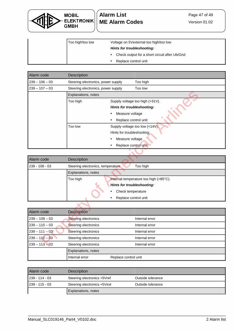
Alarm List Page 47 of 49
ME Alarm Codes Version 01.02
Manual_SLC019146_Part4_V0102.doc 2 Alarm list
Too high/too low Voltage on 5Vexternal too high/too low
Hints for troubleshooting:
• Check output for a short circuit after Ub/Gnd
• Replace control unit
Alarm code Description
239 – 106 – 03 Steering electronics, power supply Too high
239 – 107 – 03 Steering electronics, power supply Too low
Explanations, notes
Too high Supply voltage too high (>31V).
Hints for troubleshooting:
• Measure voltage
• Replace control unit
Too low Supply voltage too low (<14V).
Hints for troubleshooting:
• Measure voltage
• Replace control unit
Alarm code Description
239 - 108 - 03 Steering electronics, temperature Too high
Explanations, notes
Too high Internal temperature too high (>85°C).
Hints for troubleshooting:
• Check temperature
• Replace control unit
Alarm code Description
239 – 109 – 03 Steering electronics Internal error
239 – 110 – 03 Steering electronics Internal error
239 – 111 – 03 Steering electronics Internal error
239 – 112 – 03 Steering electronics Internal error
239 – 113 – 03 Steering electronics Internal error
Explanations, notes
Internal error Replace control unit
Alarm code Description
239 - 114 - 03 Steering electronics +5Vref Outside tolerance
239 - 115 - 03 Steering electronics +5Vext Outside tolerance
Explanations, notes
Prope
rty o
f Am
erica
n Airli
nes
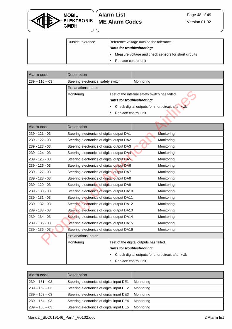
Alarm List Page 48 of 49
ME Alarm Codes Version 01.02
Manual_SLC019146_Part4_V0102.doc 2 Alarm list
Outside tolerance Reference voltage outside the tolerance.
Hints for troubleshooting:
• Measure voltage and check sensors for short circuits
• Replace control unit
Alarm code Description
239 – 116 – 03 Steering electronics, safety switch Monitoring
Explanations, notes
Monitoring Test of the internal safety switch has failed.
Hints for troubleshooting:
• Check digital outputs for short circuit after +Ub
• Replace control unit
Alarm code Description
239 - 121 - 03 Steering electronics of digital output DA1 Monitoring
239 - 122 - 03 Steering electronics of digital output DA2 Monitoring
239 - 123 - 03 Steering electronics of digital output DA3 Monitoring
239 - 124 - 03 Steering electronics of digital output DA4 Monitoring
239 - 125 - 03 Steering electronics of digital output DA5 Monitoring
239 - 126 - 03 Steering electronics of digital output DA6 Monitoring
239 - 127 - 03 Steering electronics of digital output DA7 Monitoring
239 - 128 - 03 Steering electronics of digital output DA8 Monitoring
239 - 129 - 03 Steering electronics of digital output DA9 Monitoring
239 - 130 - 03 Steering electronics of digital output DA10 Monitoring
239 - 131 - 03 Steering electronics of digital output DA11 Monitoring
239 - 132 - 03 Steering electronics of digital output DA12 Monitoring
239 - 133 - 03 Steering electronics of digital output DA13 Monitoring
239 - 134 - 03 Steering electronics of digital output DA14 Monitoring
239 - 135 - 03 Steering electronics of digital output DA15 Monitoring
239 - 136 - 03 Steering electronics of digital output DA16 Monitoring
Explanations, notes
Monitoring Test of the digital outputs has failed.
Hints for troubleshooting:
• Check digital outputs for short circuit after +Ub
• Replace control unit
Alarm code Description
239 – 161 – 03 Steering electronics of digital input DE1 Monitoring
239 – 162 – 03 Steering electronics of digital input DE2 Monitoring
239 – 163 – 03 Steering electronics of digital input DE3 Monitoring
239 – 164 – 03 Steering electronics of digital input DE4 Monitoring
239 – 165 – 03 Steering electronics of digital input DE5 Monitoring
Prope
rty o
f Am
erica
n Airli
nes
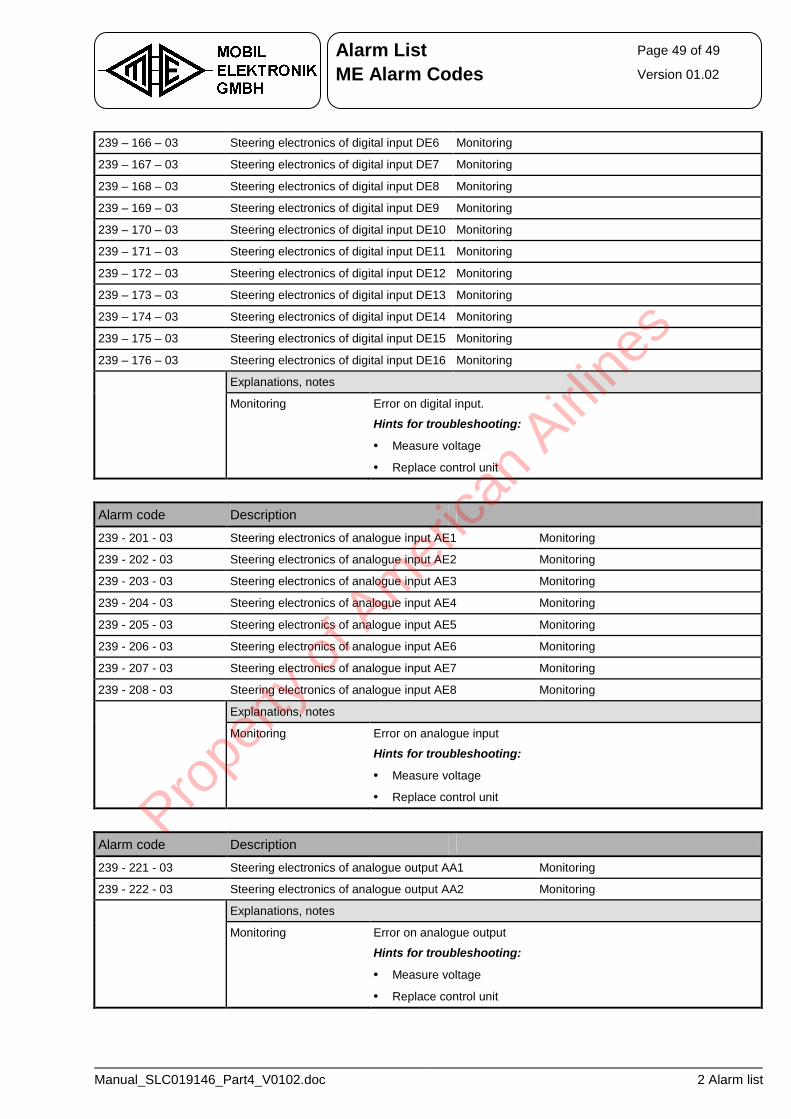
Alarm List Page 49 of 49
ME Alarm Codes Version 01.02
Manual_SLC019146_Part4_V0102.doc 2 Alarm list
239 – 166 – 03 Steering electronics of digital input DE6 Monitoring
239 – 167 – 03 Steering electronics of digital input DE7 Monitoring
239 – 168 – 03 Steering electronics of digital input DE8 Monitoring
239 – 169 – 03 Steering electronics of digital input DE9 Monitoring
239 – 170 – 03 Steering electronics of digital input DE10 Monitoring
239 – 171 – 03 Steering electronics of digital input DE11 Monitoring
239 – 172 – 03 Steering electronics of digital input DE12 Monitoring
239 – 173 – 03 Steering electronics of digital input DE13 Monitoring
239 – 174 – 03 Steering electronics of digital input DE14 Monitoring
239 – 175 – 03 Steering electronics of digital input DE15 Monitoring
239 – 176 – 03 Steering electronics of digital input DE16 Monitoring
Explanations, notes
Monitoring Error on digital input.
Hints for troubleshooting:
• Measure voltage
• Replace control unit
Alarm code Description
239 - 201 - 03 Steering electronics of analogue input AE1 Monitoring
239 - 202 - 03 Steering electronics of analogue input AE2 Monitoring
239 - 203 - 03 Steering electronics of analogue input AE3 Monitoring
239 - 204 - 03 Steering electronics of analogue input AE4 Monitoring
239 - 205 - 03 Steering electronics of analogue input AE5 Monitoring
239 - 206 - 03 Steering electronics of analogue input AE6 Monitoring
239 - 207 - 03 Steering electronics of analogue input AE7 Monitoring
239 - 208 - 03 Steering electronics of analogue input AE8 Monitoring
Explanations, notes
Monitoring Error on analogue input
Hints for troubleshooting:
• Measure voltage
• Replace control unit
Alarm code Description
239 - 221 - 03 Steering electronics of analogue output AA1 Monitoring
239 - 222 - 03 Steering electronics of analogue output AA2 Monitoring
Explanations, notes
Monitoring Error on analogue output
Hints for troubleshooting:
• Measure voltage
• Replace control unit
Prope
rty o
f Am
erica
n Airli
nes

Prope
rty o
f Am
erica
n Airli
nes