Embed Size (px)
Citation preview

7.3 Electric FieldsIf you have typed a letter on a computer, heard musical tones from a cellphone, or even just pressed a floor button in an elevator, then you have applied an electric force. In fact, almost everywhere you go you will find a device that, in one way or another, uses electric fields. An electric field is what causes the electric force. At the dentist’s office, the X-ray machine uses an electric field to accelerate electrons as part of the process for producing X-rays. At coal-burning power plants, electric fields in smokestack scrubbers remove soot and other pollutants before gases are released into the air. Even when you are speaking into a telephone or listening to the other person on the line, electric fields help convert sound to electricity and back to sound again.
The liquid crystal display (LCD) is a device that uses electric fields. Nearly all computer monitors, digital cameras, and smart phones use LCDs for their visual components (Figure 1). LCDs consist of a liquid crystal between two transparent sheets of glass or plastic, with a thin conducting material on the outside of the sheets. An electric field across the crystal causes its molecular arrangement to change, so that light passing through it is made either lighter or darker, depending on the design of the device. In this way, small changes in the electric field can make nearly any pattern appear on the LCD.
Properties of Electric FieldsWe can describe the electric force between a pair of charges using Coulomb’s law, but there is another way to describe electric forces. Suppose there is a single isolated point charge that is far from any other charges. This charge produces an electric field, a region in which a force is exerted on an electric charge. The electric field is similar to the gravitational field near an isolated mass, as discussed in Chapter 6. Were another charge to enter this field, the electric field would exert a force on it, much as a gravitational field exerts a force on a mass. The electric field has both magnitude and direction, so electric field is a vector denoted by e>.
Consider a particular point in space where there is a uniform electric field e>
(Figure 2). A point charge or an arrangement of several charges may have produced this field. A charge q at this location in the field will be affected by the electric field and experience an electric force given by
F>E 5 qe
>
The electric force, F>E, is thus parallel to e>, with direction depending on whether
the charge is positive or negative.
electric field (e$) the region in which a force is exerted on an electric charge; the electric force per unit positive charge; unit is N/C
Figure 1 LCDs use changing electric fields to alter the crystal’s optical properties, creating images.
334 Chapter 7 • Electric Fields NEL
8160_CH07_p318-345.indd 334 4/27/12 10:37 AM

The charge q1, or the charge affected by the field, in Figure 2 is called a test charge. As a convention, physicists use a positive test charge to determine direction. By measuring the force on a positive test charge, you can determine the magnitude and direction of the electric field at the location of the test charge. Since we are working with a positive test charge, q1, the electric field points in the same direction as the force that the test charge experiences. If q1 happens to be a negative charge, then the direction of the elec-tric field is in the opposite direction of the force that the negative charge experiences. The units for the electric field can be determined from the equation relating electric force to electric field. Force is measured in newtons (N), and charge is measured in coulombs (C), so the electric field is expressed in newtons per coulomb (N/C).
test charge
force on test charge
q2
q1
FE � q1e
e
Figure 2 The electric field at a particular point in space is related to the electric force on a test charge q1 at that location.
The electric field e> also relates to Coulomb’s law for electric force. Coulomb’s
law for electric force allows you to calculate the electric field using the amount of charge that produces the field, q2, and the distance of the field from the charge. As an example, calculate the magnitude of the electric field at a distance r from a charge q2. The test charge is, once again, q1. According to Coulomb’s law, the electric force exerted on q1 has a magnitude of
FE 5kq1q2
r 2
FE 5 q1kq2
r 2
Inserting this expression into the equation relating electric force to the electric field gives the result
qe 5 FE
qe 5 q1kq2
r 2
In this equation q 5 q1, so we get
e 5kq2
r 2
This is the magnitude of the electric field at a distance r from a point charge q2. The direction of e> lies along the line that connects the charge producing the field, q2, to the point where the field is measured. The direction of the electric field is determined by a positive test charge. If q2 is positive, then a positive test charge will be repelled away from it, and thus the electric field points in a direction away from a positive charge. If q2 is negative, then a positive test charge will be attracted toward it and thus the electric field points in a direction toward a negative charge. As a result of the direction of the electric field depending on the type of charge and the location in relation to the charge, we do not include the signs of charges in the equations to avoid implying a direction.
7.3 Electric Fields 335NEL
8160_CH07_p318-345.indd 335 4/27/12 10:37 AM

In Tutorial 1, you will solve problems related to the electric field in both one and two dimensions. When using the equation for electric field, the symbol q really means the absolute value of q, just like it does for Coulomb’s law.
Two point charges are 45 cm apart (Figure 3). The charge on q1 is 3.3 3 1029 C, and the charge on q2 is 21.00 3 1028 C.
q1P
q2
r1 r2
��
Figure 3
(a) Calculate the net electric field at point P, 27 cm from the positive charge, on the line connecting the charges.
(b) A new charge of 12.0 3 10–12 C is placed at P. Determine the electric force on this new charge.
Solution (a) Given: r12 5 45 cm; r1 5 27 cm; q1 5 3.3 3 10–9 C;
q2 5 21.00 3 10–8 C; k 5 8.99 3 109 N.m2/C2
Required: net electric field e>net at point P
Analysis: The net electric field at point P equals the vector sum of the electric fields from the charges producing the
fields. Use the equation e 5kq
r 2 to calculate e for each
of the charges q1 and q2 at point P. Then determine the direction of each field based on the signs of the charges. Combine the two vector quantities to calculate e
>net.
r2 5 r12 2 r1 5 45 cm 2 27 cm 5 18 cm 5 0.18 m
Solution: Calculate the magnitude of the electric field at a distance r1 from charge q1 and determine the field’s direction.
e1 5kq1
r 12
5 a8.99 3 109
N #m2
C2 b 13.3 3 1029 C2
10.27 m2 2e1 5 4.070 3 102 N/C 1two extra digits carried2Since q1 is a positive charge, the electric field on a positive test charge at P will be directed away from q1.
e>1 5 4.070 3 102 N/C 3right 4
Calculate the magnitude of the electric field at a distance r2 from charge q2 and determine the field’s direction.
e2 5kq2
r 22
5 a8.99 3 109
N #m2
C2 b 11.00 3 1028 C2
10.18 m2 2e2 5 2.775 3 103 N/C 1two extra digits carried2Since q2 is a negative charge, the electric field on a positive test charge at P will be directed toward q2.
e>2 5 2.775 3 103 N/C 3right 4
Now determine the vector sum of the two electric fields. Choose right as positive, so left is negative.
e>net 5 e
>1 1 e
>2
5 14.070 3 102 N/C 1 2.775 3 103 N/C
5 13.182 3 103 N/C 1two extra digits carried2e>net 5 3.2 3 103 N/C 3right 4
Statement: The net electric field is 3.2 3 103 N/C to the right of point P.
(b) Given: e>net 5 3.182 3 103 N/C, directed to the right of point P;
q 5 12.0 3 10–12 C
Required: net electric force F>Enet
Analysis: Use the equation F>E 5 qe
>to calculate the net
electric force for the test charge q at point P.
Solution: Use the sign of the charge to determine the direction of the electric field. Since the charge is positive, the electric force is directed to the right. Choose right as positive, so left is negative.
F>Enet
5 qe>net
5 112.0 3 10212 C 2 113.182 3 103 N/C2 5 16.4 3 1029 NF>Enet
5 6.4 3 1029 N 3right 4Statement: The electric force acting on the new charge at point P is 6.4 3 1029 N to the right of point P.
Sample Problem 1: Electric Field Due to Two Point Charges in One Dimension
Tutorial 1 Determining Electric Fields
This Tutorial shows how to determine the electric field due to charge distribution at a point some distance from the charge.
336 Chapter 7 • Electric Fields NEL
8160_CH07_p318-345.indd 336 4/27/12 10:37 AM
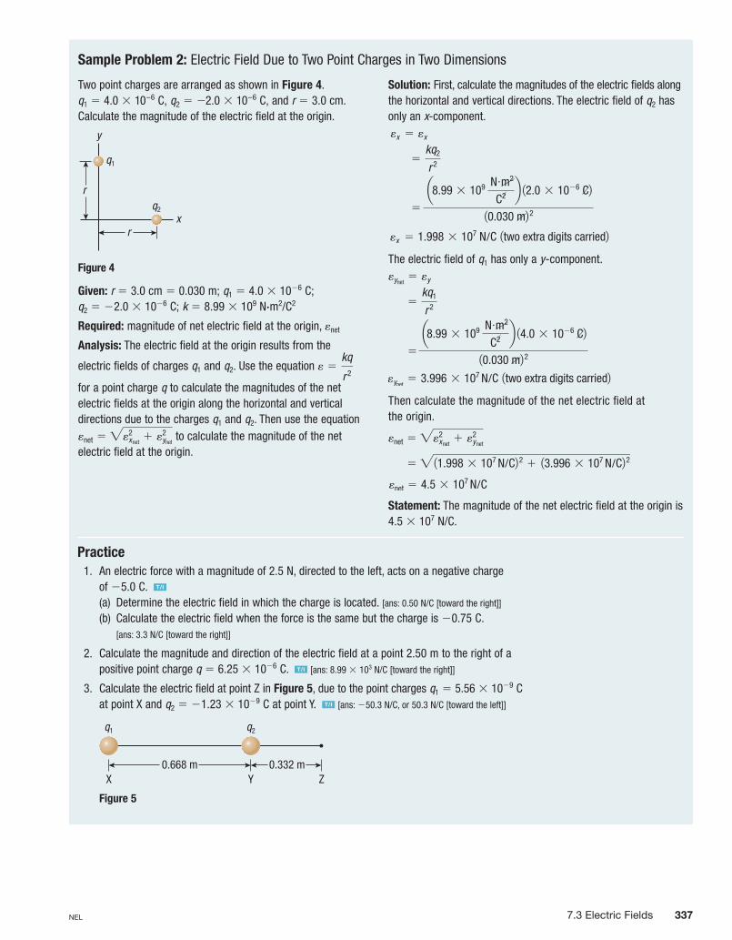
Practice 1. An electric force with a magnitude of 2.5 N, directed to the left, acts on a negative charge
of 25.0 C. T/I
(a) Determine the electric field in which the charge is located. [ans: 0.50 N/C [toward the right]]
(b) Calculate the electric field when the force is the same but the charge is 20.75 C. [ans: 3.3 N/C [toward the right]]
2. Calculate the magnitude and direction of the electric field at a point 2.50 m to the right of a positive point charge q 5 6.25 3 1026 C. T/I [ans: 8.99 3 103 N/C [toward the right]]
3. Calculate the electric field at point Z in Figure 5, due to the point charges q1 5 5.56 3 1029 C at point X and q2 5 21.23 3 1029 C at point Y. T/I [ans: 250.3 N/C, or 50.3 N/C [toward the left]]
q1 q2
0.668 m 0.332 mX Y Z
Figure 5
Sample Problem 2: Electric Field Due to Two Point Charges in Two Dimensions
Two point charges are arranged as shown in Figure 4. q1 5 4.0 3 10–6 C, q2 5 22.0 3 10–6 C, and r 5 3.0 cm. Calculate the magnitude of the electric field at the origin.
r
rq2
q1
x
y
Figure 4
Given: r 5 3.0 cm 5 0.030 m; q1 5 4.0 3 1026 C; q2 5 22.0 3 1026 C; k 5 8.99 3 109 N.m2/C2
Required: magnitude of net electric field at the origin, enet
Analysis: The electric field at the origin results from the
electric fields of charges q1 and q2. Use the equation e 5kq
r 2
for a point charge q to calculate the magnitudes of the net electric fields at the origin along the horizontal and vertical directions due to the charges q1 and q2. Then use the equation enet 5 "e2
xnet1 e2
ynet to calculate the magnitude of the net
electric field at the origin.
Solution: First, calculate the magnitudes of the electric fields along the horizontal and vertical directions. The electric field of q2 has only an x-component. ex 5 ex
5kq2
r 2
5
a8.99 3 109 N #m2
C2 b 12.0 3 1026 C210.030 m2 2
ex 5 1.998 3 107 N/C 1two extra digits carried2
The electric field of q1 has only a y-component.eynet
5 ey
5kq1
r 2
5
a8.99 3 109 N #m2
C2 b 14.0 3 1026 C210.030 m2 2
eynet5 3.996 3 107
N/C 1two extra digits carried2Then calculate the magnitude of the net electric field at the origin.
enet 5 "e2xnet
1 e2ynet
5 "11.998 3 107
N/C2 2 1 13.996 3 107 N/C2 2
enet 5 4.5 3 107 N/C
Statement: The magnitude of the net electric field at the origin is 4.5 3 107 N/C.
7.3 Electric Fields 337NEL
8160_CH07_p318-345.indd 337 4/27/12 10:37 AM

According to Coulomb’s law, the force between two point charges varies as 1r 2
,
where r is the separation between the two charges. In a similar way, the electric field produced by a point charge also varies as
1r 2
. The electric field thus obeys an inverse-
square law, just as the gravitational force does (Figure 7(a)).The magnitude of the electric force is proportional to the density of field lines—that
is, the number of field lines per unit area of space—at some distance r from the charge or charges producing the field. For a point charge q (Figure 7(b)), the density of field lines decreases farther away from the charge. The field lines from q spread out through a surface area. Therefore, the number of field lines per unit area (A), and thus the respective strengths of the electric field and electric force, decreases as r2 increases.
Figure 6 Electric field lines near a point charge placed at the origin. (a) If the charge is positive, the electric field lines are directed outward, away from the charge. (b) If the charge is negative, the electric field lines are directed inward, toward the charge.
�q
e
�q
e
(a) (b)
Figure 7 (a) The gravitational force lines from a mass M spread out as r increases in all directions. (b) The electric field lines from a charge q also spread out in all directions. Both types of field lines pass through larger spherical surface areas at greater distances. The surface areas (A) over which the fields act increase as r 2 increases, so the fields themselves exert inverse-square forces.
M
r1
r2
(a)
q
A2 ∝ r22
portions of aspherical surface
r1
r2
A1 ∝ r12
(b)
Electric Field LinesAn electric field exists in a region around a charge. The field and its properties can be represented with electric field lines. These electric field lines can help us determine the direction of the force on a nearby test charge.
As was stated earlier, electric fields point away from positive charges and toward negative charges. This convention is based on using a positive test charge to deter-mine direction. To show what the electric field would look like around a positive point charge, we draw electric field lines that extend radially outward from the charge, as shown in Figure 6(a). For a negative charge, the field lines are directed inward, toward the charge (Figure 6(b)). As you may expect, the electric field lines are parallel to e>, and the density of the field lines is proportional to the magnitude of e>. In both parts of Figure 6, the field lines are densest near the charges. In both cases,
the magnitude of e> increases as the distance to the charge decreases.
electric field lines the continuous lines of force around charges that show the direction of the electric force at all points in the electric field
338 Chapter 7 • Electric Fields NEL
8160_CH07_p318-345.indd 338 4/27/12 10:37 AM

Another interesting aspect of the electric force relates to the question of action at a distance. How do two point charges that interact through Coulomb’s law “know” about each other? In other words, how does one charge transmit electric force to another charge? In terms of the electric field lines, every charge generates (or carries with it) an electric field, through which the electric force is transmitted.
Electric DipolesConsider the two point particles with equal but opposite charge in Figure 8. Charges 2q and 1q, where q is the positive magnitude of the charge, are separated by a small distance r. This charge configuration is called an electric dipole.
r
Figure 8 Two opposite charges separated by a distance r form an electric dipole.
The two charges in an electric dipole give rise to a more complicated electric field than the one associated with a single electric charge. This is because the electric fields around the individual charges interact most strongly with each other at close distances, such as those that are similar in size to the dipole separation. Initially, the fields at the negative charge radiate inward toward the charge, and the fields at the positive charge radiate outward from the charge (Figure 9(a)). As the fields extend into the space around the other charge, they interact with each other, producing field lines that bend toward the other charge (Figure 9(b)).
electric dipole a pair of equal and opposite electric charges with centres separated by a small distance
Figure 9 The electric field lines around each individual charge of an electric dipole (a) are affected by the field lines from the other charge, causing them to bend (b). It is important to note that the field lines extend in three dimensions around the charges, and that the view depicted here is of the field lines in a plane perpendicular to the line of sight.
�q�q
field lines from�q alone
field lines from�q alone
(a)
�q�q
(b)
Notice that, along the vertical axis midway between the two charges, the electric field is parallel to the line connecting the two charges. This remains true along the vertical axis at all distances from the dipole, although the magnitude of the electric field decreases at distances that are farther from the dipole. The direction of this elec-tric field always points from the positive charge to the negative charge.
Although the field lines of a dipole merge at the midpoint, field lines do not cross. Instead, the cumulative effect, or the vector sum, of the electric fields from both charges produces a net electric field. That net electric field is represented by the elec-tric field line.
7.3 Electric Fields 339NEL
8160_CH07_p318-345.indd 339 4/27/12 10:37 AM

Notice that, farther away from the charges, the field behaviour starts to resemble that of a single charge. That is, the field lines appear to be radiating from a single point charge. This makes sense because, at a large distance from the two charges, the separation between them is not noticeable, and both charges have the same sign. Midway between the two charges, there is a gap where there are no field lines. This is expected because the vector sum of the two electric fields from both charges is zero at the midpoint.
Note that this electric field pattern would be the same if the two charges were both negative. The difference would be in the direction in which the field lines were pointing but not the shape of the combined fields.
Finally, consider a dipole-like arrangement of two charges that have different magnitudes and signs. If the positive charge 1q is replaced with a charge 12q, the symmetry of the dipole field is altered (Figure 11 on the next page). This is because the number of field lines for each charge is proportional to the magnitude of that charge. The number of field lines leaving the positive charge is therefore twice the number of field lines meeting at the negative charge. Half of these lines converge on the negative charge, while the other half emanate outward, as if there were only one charge (12q). At large distances, where r is much greater than the charge separation, the electric field radiates outward as it would for a charge of 12q.
The field-line pattern for unequal and opposite charges includes regions near the charges where the density of field lines becomes very high. Note that this does not mean that the electric field is stronger in these regions. The electric field is still strongest along the line connecting the charges. Electric field patterns can become very complex, but many simulations exist to show what the electric field would look like in a multi-charge system. WEB LINK
�q�q
Figure 10 Two identical charges separated by a small distance produce this electric field pattern. Again, the field lines occupy all the space around the charges. This illustration shows how they appear in a plane. Note that the electric field is zero along the line that bisects the line connecting the charges.
Now consider an arrangement of charges slightly different from an electric dipole. In this case, a positive charge, 1q, replaces the negative charge, 2q, so that the two charges are equal and alike. Now the electric field lines extend outward from both charges. Instead of the field lines from a positive charge merging with the lines from a negative charge, the lines from similar charges do not connect at any point. This arrangement produces a disk-shaped region of zero electric field everywhere around the midpoint between the two charges (Figure 10).
340 Chapter 7 • Electric Fields NEL
8160_CH07_p318-345.indd 340 4/27/12 10:37 AM

�2q �q
Figure 11 The electric field lines around a dipole consisting of charges 2q and 12q. The number of lines from the larger charge is twice the number of lines from the smaller charge. Half of these lines extend from the positive charge to the negative charge. The other half extend outward, as if there were only one charge, 12q.
Uniform Electric FieldsSo far, you have learned about electric fields that vary with distance from a charge. In the case of a dipole, for instance, the strength of the electric field varies with the number of charges, their placement, and the distance from the charges.
A different electric field arises from a different type of dipole. Instead of point charges, suppose you have two parallel planes of charge. As with the dipole, one plane has a positive charge and the other plane has a negative charge. In both cases, the charge spreads uniformly along each plane.
Just as the electric field along the line connecting two unlike charges extends straight from the positive to the negative charge, the electric field between the planes of charge extends from the positive plane of charge to the negative plane and is uniform. These field lines are straight, parallel to each other, and perpendicular to the planes of charge. At any location between the planes, the electric field has the same magnitude and direction. Outside the planes, the vector sum of the electric fields from all the individual charges in the two parallel planes yields a value of zero.
This description of planes of charges involves “infinite” parallel planes carrying “infinite” amounts of charge and thus does not exist in real-world scenarios. However, you can create a close approximation by using two large conducting plates charged by dry cells. These plates are parallel and carry equal and opposite charges. As long as the separation between the plates is much smaller than their surface area, the electric field between the plates remains uniform (Figure 12). In fact, except near the edges of the plates, the magnitude of the electric field depends only on the amount of charge, the area of the plates, and the material between the plates.
total charge � �q� � � �
� � ��total charge � �q
�
�
� � � �
� � ��
�
�
Figure 12 The electric field between two parallel conducting plates is uniform in direction and magnitude.
7.3 Electric Fields 341NEL
8160_CH07_p318-345.indd 341 4/27/12 10:37 AM

Earth’s Electric FieldEnergy from the Sun bombards Earth’s upper atmosphere. Some of this energy strips electrons from atoms, leaving a region of positively charged ions and free electrons. Some of the electrons recombine with the ions, but others travel into space and other regions of the atmosphere. Th is region, appropriately called the ionosphere, therefore has a positive charge and is able to conduct electricity.
In contrast to the ionosphere, Earth’s surface is more negatively charged. Both areas tend to stay charged, so that a permanent electric fi eld exists throughout the atmosphere. Near Earth’s surface, when the sky is clear of storms, the electric fi eld has an average magnitude of about 120 N/C.
Th is electric fi eld varies seasonally, but the greatest and most sudden change occurs during thunderstorms, when the atmospheric electric fi eld can reverse direc-tion. Cloud-to-ground lightning, which oft en accompanies these storms, is both very common and potentially very destructive, so it is essential that scientists understand how Earth’s electric fi eld changes during storms, and what fi eld conditions are likely to result in a lightning strike.
One device, called an electric fi eld mill, or just fi eld mill, is widely used to measure Earth’s electric fi eld. A fi eld mill makes use of the uniform electric fi eld between two parallel conducting plates and detects changes in the fi eld strength at a given location.
Th e design of a fi eld mill incorporates two circular conducting plates (Figure 13). Th e conducting plate at the front of the mill is the sensor plate. Th is part of the mill is exposed to the atmospheric electric fi eld. A set of motor-driven, rotating shutter blades (the mill) exposes the sensor plate for a short time and then blocks the plate from the electric fi eld for an identical length of time. During exposure, the plate becomes charged. During non-exposure, an analyzer circuit measures the elec-tric fi eld between the charged sensor plate and the uncharged detector plate. Th is process repeats continuously, providing information about variations in the fi eld strength of Earth’s electric fi eld over a given time interval and in a particular region of the atmosphere. CAREER LINK
Field mills have fairly simple designs and generally perform reliably. Although oft en set up in permanent positions on the ground, fi eld mills located in balloons and aircraft measure fi eld changes at diff erent elevations. Field mills are used in cases where lightning could do extreme damage, such as to spacecraft before launch.
Figure 13 A fi eld mill measures the electric fi eld between two parallel conducting plates to determine the changes in Earth’s electric fi eld.
conductingsensorplate
detectorplate
electric fieldanalyzercircuit
rotatingshutter blade
(the mill)
shutter motor
You can apply what you have learned about electric fi elds to the Unit Task on page 422.
UNIT TASK BOOKMARK
342 Chapter 7 • Electric Fields NEL
8160_CH07_p318-345.indd 342 4/27/12 10:37 AM

Some of the devices used for home air purifi cation use the basic principles of elec-trostatic precipitators. However, the results from these air cleaners have been mixed, partly because of the comparatively low levels of particles in household air, and partly because the electric fi elds are not as strong as in industrial precipitators.
Electrostatic PrecipitatorsDuring the Industrial Age, heavily polluted air resulted from the smoke pouring out of chimneys and smokestacks. Most of these emissions, called fl ue gases because they passed through the fl ues of chimneys, consisted of gases such as nitrogen and carbon dioxide, both of which are clear substances. However, tiny particles of carbon, sulfur compounds, and dust produced by various chemical processes and combustion com-bined with the gases. Th ese particles gave the air its smoky appearance.
Today, industrial processes continue to pollute our air. Air containing polluting gases leads to many environmental concerns such as climate change and acid precipi-tation. Acid precipitation is known to harm both plant and aquatic life. Th e polluting gases also aff ect the respiratory health of not only the people who live nearby but also those who live where the prevailing winds tend to push the gases.
In recent years, devices called electrostatic precipitators have reduced the numbers of these particles released into the atmosphere. Electrostatic precipitators use electric fi elds to remove extremely small particles of soot, dust, and ash from fl ue gases and other emissions produced by combustion, smelting, and refi ning.
Th e exact arrangements of diff erent electrostatic precipitators vary, but the basic principle is the same in all of them. In the design shown in Figure 14, the fl ue gas and particles it contains pass between a grid of negatively charged conducting wires and a conducting plate carrying a positive charge. Th e wires transfer electrons to the various particles that come into contact with the wires, making the particles negatively charged. Th e electric fi eld between the wires and the plates is about 1 3 106 N/C, so the force drawing these negatively charged particles toward the positively charged plates is very large. Shaking the plates from time to time loosens the particles that accumu-late on them. A storage (collection) hopper below the precipitator collects this refuse. Repeating the procedure of passing the fl ue gas through several series of plates and wires removes about 99 % of the various particles from the gas.
collection hopper
plate (+)
flue gas
wires (–)
Figure 14 An electrostatic precipitator uses electric fi elds to remove particles from fl ue gases.
7.3 Electric Fields 343NEL
8160_CH07_p318-345.indd 343 4/27/12 10:37 AM

Electric Fields in NatureElectric fi elds are also produced by animals. Th ese fi elds are oft en weak and produced by ordinary actions, such as motion in the muscles. Some animals have organs that detect and respond to these weak electric fi elds. Hammerhead sharks, for instance, detect fi elds as low as 6 N/C in fi sh that hide beneath the sand or in tunnelled shelters along shallow ocean bottoms.
Th e hammerhead shark swims close to the sandy ocean fl oor (Figure 15). It preys on goby, small fi sh that hide in sand-covered holes. A goby produces electric fi elds from muscular movements of its fi ns or gills. Although the shark cannot see the goby, it can detect these electric fi elds up to 25 cm above the sand. Having detected the goby, the hammerhead shark swims in a fi gure eight until it pinpoints the location of greatest electric fi eld strength and then catches and consumes the goby.
Many fi sh use electric fi elds to detect or stun their prey, or to ward off predators. Some examples are electric eels, electric catfi sh, elephant fi sh, Nile knifefi sh, and torpedo fi sh.
1. Research one of these fi sh on the Internet, and determine how it detects or uses electric fi elds.
2. Compare this fi sh’s abilities with those of the hammerhead shark.
3. Write a brief report of your fi ndings that includes answers to the following questions.
A. What types of behaviours that are related to electric fi elds are typical for the organism you chose? T/I
B. Why are fi sh that stun prey with electric fi elds typically freshwater species? T/I
C. Many fi sh are able to detect weak electric fi elds from prey that live in rivers with large amounts of silt and soil suspended in the water. Why would an adaptation such as electric-fi eld detection be benefi cial for these fi sh? T/I
Fish and Electric Fields
Research This
Skills: Researching, Communicating SKILLSHANDBOOK A4.1
WEB LINK
Figure 15 A hammerhead shark can detect the electric fi elds pro duced by the movements of its prey.
344 Chapter 7 • Electric Fields NEL
8160_CH07_p318-345.indd 344 4/27/12 10:37 AM

Questions
1. A proton and an electron are placed in a uniform electric field. Comment on the magnitudes of the forces experienced by both. K/U
2. Calculate the magnitude of the electric field at a distance of 1.5 m from a point charge with q 5 3.5 C. K/U
3. A point particle of charge q1 5 4.5 3 1026 C is placed on the x-axis at x 5 210 cm. A second particle of charge q2 is placed on the x-axis at x 5 125 cm. The electric field at the origin is zero. Determine the charge q2. K/U T/I
4. A ring with a radius of 25 cm and total charge 5.00 3 1024 C is centred at the origin as shown in Figure 16. The charge is distributed uniformly around the ring. Calculate the electric field at the origin. (Hint: Think of applying symmetry.) K/U T/I
y
rx
���
���
�
�
�
�
�
�
Figure 16
5. When drawing electric field lines, what determines the number of lines originating from a charge? K/U
Summary
• An electric field exists in a region of space when a test charge placed at any point in the region has a force exerted upon it.
• The electric field is a vector and is denoted by e>. A test charge q will experience an electric force given by F
>E 5 qe
>. The directions of the electric force and
electric field are determined by a positive test charge.• For a point charge q2, the magnitude of the electric field at a distance r from
the charge is e 5kq2
r 2 .• Electric field lines are continuous lines of force that show the direction of
electric force at all points in the electric field around a charge or charges. • An electric dipole consists of two equal but opposite charges separated by some
small distance.• The electric field between two parallel plates of charge is uniform and
perpendicular to the plates. The electric field outside the parallel plates is zero.• One application of electric fields is in electrostatic precipitators, which use electric
fields to remove extremely small particles of soot, dust, and ash from flue gases.• Some organisms can detect the weak electric fields produced by the movement
of other organisms.
Review7.3
6. Two point particles with charges q1 and q2 are separated by a distance L, as shown in Figure 17. The electric field is zero at point A, which is a distance L4 from q1. Determine the ratio q1:q2. K/U T/I
y
xq2
q1
L
L4
A
Figure 17
7. Five point charges, all with q 5 7.5 C, are spaced equally along a semicircle with a radius of 2.3 m, as shown in Figure 18. Calculate the electric field at the origin. K/U T/I
y
x
q
q q
Figure 18
8. Draw the electric field lines between the wires and plates of an electrostatic precipitator. T/I C
7.3 Electric Fields 345NEL
8160_CH07_p318-345.indd 345 4/27/12 10:37 AM