Embed Size (px)
Citation preview
Propeller Particulars and Scale Effect Analysis of ECO-Cap by CFD
Masafumi Okazaki, Taro Kajihama, Kenta Katayama, Yoshihisa Okada, Nakashima Propeller Co.,Ltd. Okayama/Japan, [email protected]
List of symbols
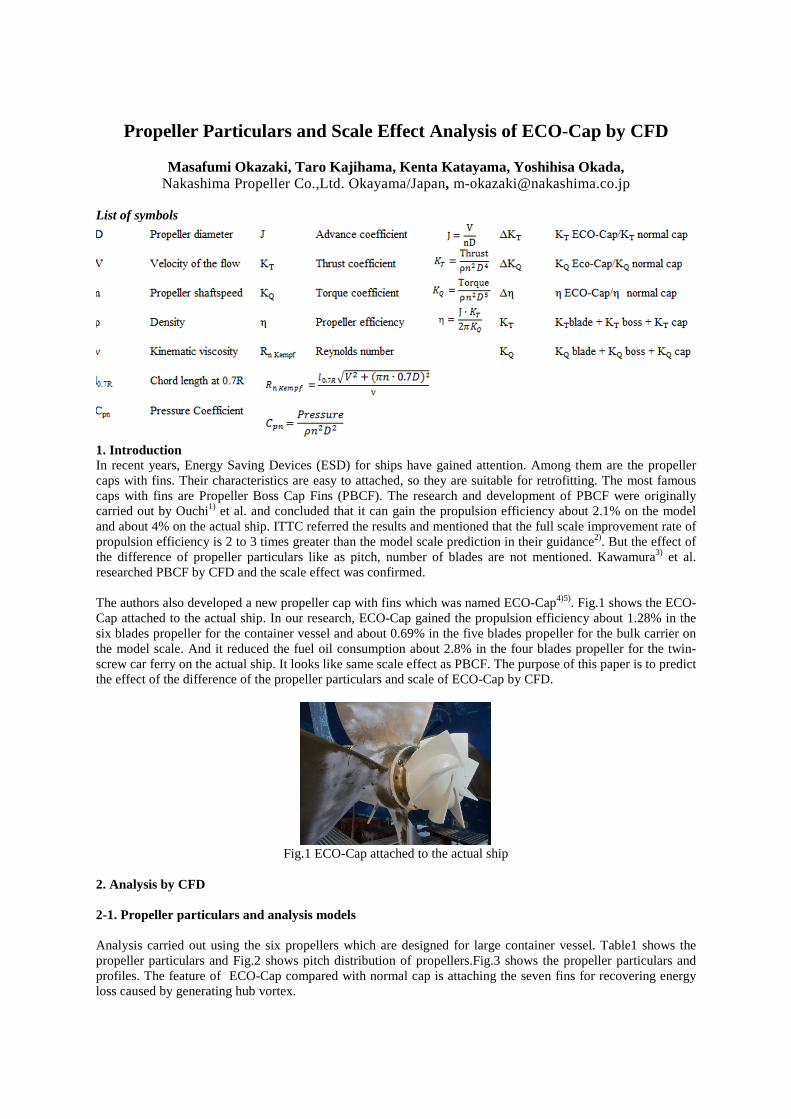
1. Introduction In recent years, Energy Saving Devices (ESD) for ships have gained attention. Among them are the propeller caps with fins. Their characteristics are easy to attached, so they are suitable for retrofitting. The most famous caps with fins are Propeller Boss Cap Fins (PBCF). The research and development of PBCF were originally carried out by Ouchi1) et al. and concluded that it can gain the propulsion efficiency about 2.1% on the model and about 4% on the actual ship. ITTC referred the results and mentioned that the full scale improvement rate of propulsion efficiency is 2 to 3 times greater than the model scale prediction in their guidance2). But the effect of the difference of propeller particulars like as pitch, number of blades are not mentioned. Kawamura3) et al. researched PBCF by CFD and the scale effect was confirmed. The authors also developed a new propeller cap with fins which was named ECO-Cap4)5). Fig.1 shows the ECO-Cap attached to the actual ship. In our research, ECO-Cap gained the propulsion efficiency about 1.28% in the six blades propeller for the container vessel and about 0.69% in the five blades propeller for the bulk carrier on the model scale. And it reduced the fuel oil consumption about 2.8% in the four blades propeller for the twin-screw car ferry on the actual ship. It looks like same scale effect as PBCF. The purpose of this paper is to predict the effect of the difference of the propeller particulars and scale of ECO-Cap by CFD.
Fig.1 ECO-Cap attached to the actual ship
2. Analysis by CFD 2-1. Propeller particulars and analysis models Analysis carried out using the six propellers which are designed for large container vessel. Table1 shows the propeller particulars and Fig.2 shows pitch distribution of propellers.Fig.3 shows the propeller particulars and profiles. The feature of ECO-Cap compared with normal cap is attaching the seven fins for recovering energy loss caused by generating hub vortex.
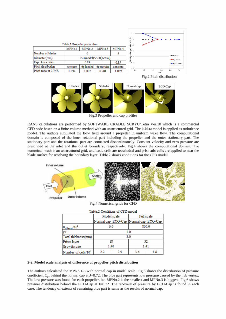
Fig.2 Pitch distribution
Fig.3 Propeller and cap profiles
RANS calculations are performed by SOFTWARE CRADLE SCRYU/Tetra Ver.10 which is a commercial CFD code based on a finite volume method with an unstructured grid. The k-kl-ω model is applied as turbulence model. The authors simulated the flow field around a propeller in uniform wake flow. The computational domain is composed of the inner rotational part including the propeller and the outer stationary part. The stationary part and the rotational part are connected discontinuously. Constant velocity and zero pressure are prescribed at the inlet and the outlet boundary, respectively. Fig.4 shows the computational domain. The
numerical mesh is an unstructured grid, and basic cells are tetrahedral and prismatic cells are applied to near the blade surface for resolving the boundary layer. Table.2 shows conditions for the CFD model.
Fig.4 Numerical grids for CFD
2-2. Model scale analysis of difference of propeller pitch distribution The authors calculated the MPNo.1-3 with normal cap in model scale. Fig.5 shows the distribution of pressure coefficient Cpn behind the normal cap at J=0.72. The blue part represents low pressure caused by the hub vortex. The low pressure was found for each propeller, but MPNo.2 is the smallest and MPNo.3 is biggest. Fig.6 shows pressure distribution behind the ECO-Cap at J=0.72. The recovery of pressure by ECO-Cap is found in each case. The tendency of extents of remaining blue part is same as the results of normal cap.
Normal cap ECO-Cap 6 blades 5 blades
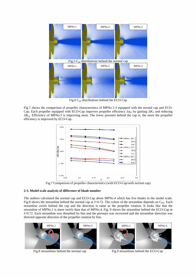
Fig.5 Cpn distributions behind the normal cap
Fig.6 Cpn distributions behind the ECO-Cap
Fig.7 shows the comparison of propeller characteristics of MPNo.1-3 equipped with the normal cap and ECO-Cap. Each propeller equipped with ECO-Cap improves propeller efficiency ∆ηO by gaining ∆KT and reducing ∆KQ. Efficiency of MPNo.3 is improving most. The lower pressure behind the cap is, the more the propeller efficiency is improved by ECO-Cap.
Fig.7 Comparison of propeller characteristics (with ECO-Cap/with normal cap)
2-3. Model scale analysis of difference of blade number The authors calculated the normal cap and ECO-Cap about MPNo.4 which has five blades in the model scale. Fig.8 shows the streamline behind the normal cap at J=0.72. The colour of the streamline depends on CPN. Each streamline swirls behind the cap and the direction is same as the propeller rotation. It looks like that the streamline of MPNo.1 is more swirly than that of MPNo.4. Fig. 9 shows the streamline behind the ECO-Cap at J=0.72. Each streamline was disturbed by fins and the pressure was recovered and the streamline direction was directed opposite direction of the propeller rotation by fins.
Fig.8 streamlines behind the normal cap Fig.9 streamlines behind the ECO-Cap
MPNo.1 MPNo.2 MPNo.3
MPNo.1 MPNo.2 MPNo.3
MPNo.1 MPNo.4 MPNo.1 MPNo.4
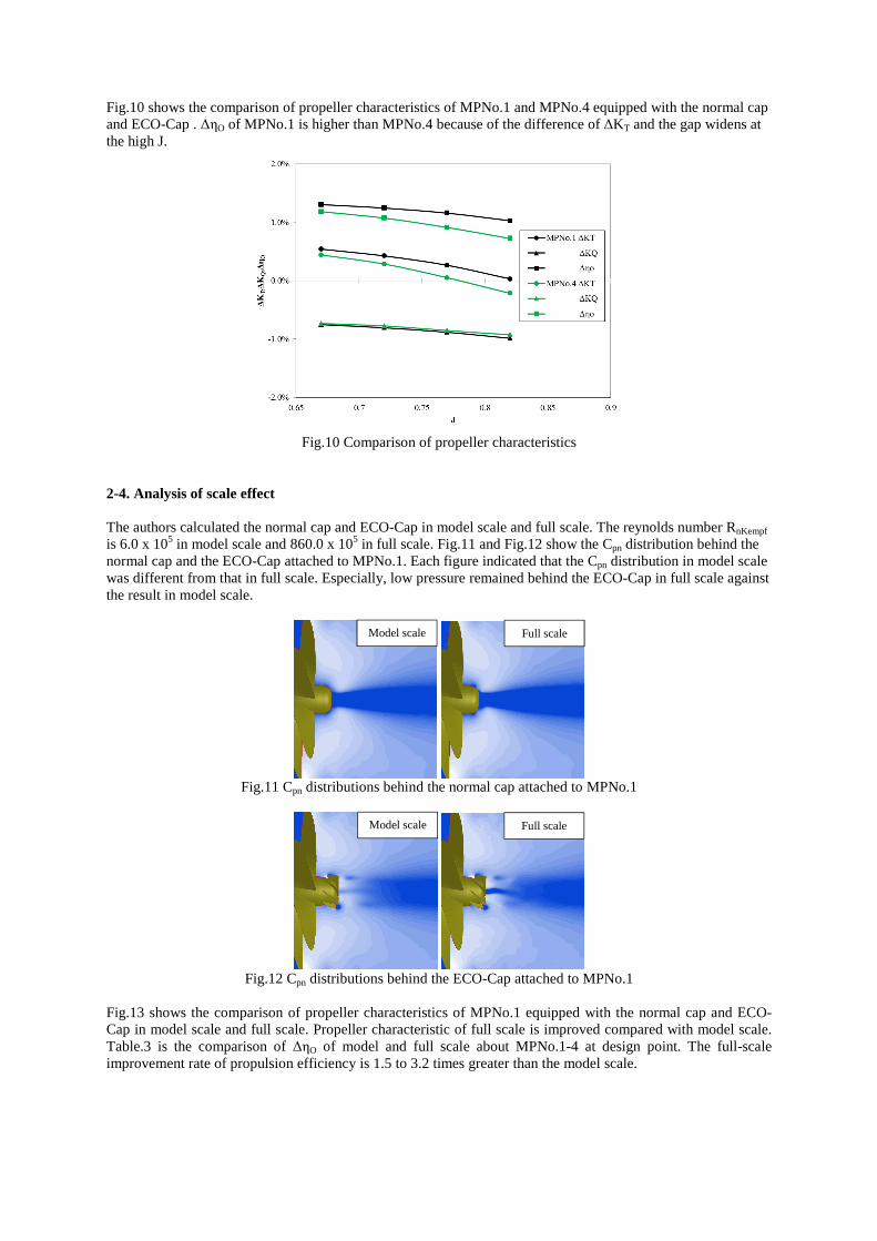
2-4. Analysis of scale effect The authors calculated the normal cap and ECO-Cap in model scale and full scale. The reynolds number RnKempf is 6.0 x 10⁵ in model scale and 860.0 x 10⁵ in full scale. Fig.11 and Fig.12 show the Cpn distribution behind the normal cap and the ECO-Cap attached to MPNo.1. Each figure indicated that the Cpn distribution in model scale was different from that in full scale. Especially, low pressure remained behind the ECO-Cap in full scale against the result in model scale.
Fig.11 Cpn distributions behind the normal cap attached to MPNo.1
Fig.12 Cpn distributions behind the ECO-Cap attached to MPNo.1
Fig.13 shows the comparison of propeller characteristics of MPNo.1 equipped with the normal cap and ECO-Cap in model scale and full scale. Propeller characteristic of full scale is improved compared with model scale. Table.3 is the comparison of ∆ηO of model and full scale about MPNo.1-4 at design point. The full-scale improvement rate of propulsion efficiency is 1.5 to 3.2 times greater than the model scale.
Fig.10 shows the comparison of propeller characteristics of MPNo.1 and MPNo.4 equipped with the normal cap and ECO-Cap . ∆ηO of MPNo.1 is higher than MPNo.4 because of the difference of ∆KT and the gap widens at the high J.
Fig.10 Comparison of propeller characteristics
Model scale Full scale
Model scale Full scale
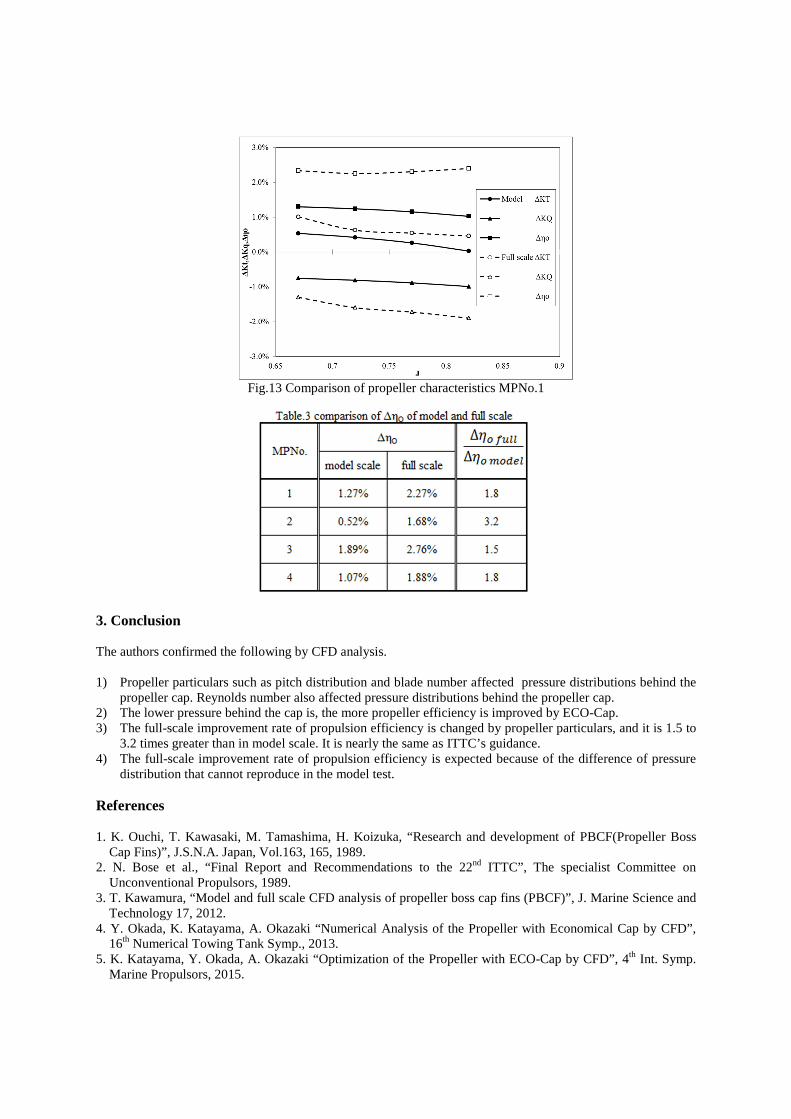
Fig.13 Comparison of propeller characteristics MPNo.1
3. Conclusion The authors confirmed the following by CFD analysis. 1) Propeller particulars such as pitch distribution and blade number affected pressure distributions behind the
propeller cap. Reynolds number also affected pressure distributions behind the propeller cap. 2) The lower pressure behind the cap is, the more propeller efficiency is improved by ECO-Cap. 3) The full-scale improvement rate of propulsion efficiency is changed by propeller particulars, and it is 1.5 to
3.2 times greater than in model scale. It is nearly the same as ITTC’s guidance. 4) The full-scale improvement rate of propulsion efficiency is expected because of the difference of pressure
distribution that cannot reproduce in the model test. References 1. K. Ouchi, T. Kawasaki, M. Tamashima, H. Koizuka, “Research and development of PBCF(Propeller Boss
Cap Fins)”, J.S.N.A. Japan, Vol.163, 165, 1989. 2. N. Bose et al., “Final Report and Recommendations to the 22nd ITTC”, The specialist Committee on
Unconventional Propulsors, 1989. 3. T. Kawamura, “Model and full scale CFD analysis of propeller boss cap fins (PBCF)”, J. Marine Science and
Technology 17, 2012. 4. Y. Okada, K. Katayama, A. Okazaki “Numerical Analysis of the Propeller with Economical Cap by CFD”,
16th Numerical Towing Tank Symp., 2013. 5. K. Katayama, Y. Okada, A. Okazaki “Optimization of the Propeller with ECO-Cap by CFD”, 4th Int. Symp.
Marine Propulsors, 2015.