Embed Size (px)
Citation preview
Manual No. 13661-00-36Revision 2February 2017
Propeller Owner's Manual and Logbook
Reversible Propeller Model HC-E3YR-7( )
Pressure Control Unit B-4270-( )
Hartzell Propeller Inc.One Propeller PlacePiqua, OH 45356-2634 U.S.A.Ph: 937-778-4200 (Hartzell Propeller Inc.)Ph: 937-778-4379 (Product Support)Product Support Fax: 937-778-4215
Propeller Owner's Manual136
61-00-36 COVERInside Cover
Rev. 2 Feb/17
(This page is intentionally blank.)
© 1982, 2013, 2017 - Hartzell Propeller Inc. - All rights reserved
Page 1 Rev. 2 Feb/17
Propeller Owner's Manual 136
MESSAGE 61-00-36
As a fellow pilot, I urge you to read this Manual thoroughly. It contains a wealth of information about your new propeller.
The propeller is among the most reliable components of your airplane. It is also among the most critical to flight safety. It therefore deserves the care and maintenance called for in this Manual. Please give it your attention, especially the section dealing with Inspections and Checks.
Thank you for choosing a Hartzell propeller. Properly maintained it will give you many years of reliable service.
Jim Brown Chairman, Hartzell Propeller Inc.
Page 2 Rev. 2 Feb/17MESSAGE 61-00-36
Propeller Owner's Manual 136
WARNINGPeople who fly should recognize that various types of risks are involved; and they should take all precautions to minimize them, since they cannot be eliminated entirely. The propeller is a vital component of the aircraft. A mechanical failure of the propeller could cause a forced landing or create vibrations sufficiently severe to damage the aircraft, possibly causing it to become uncontrollable.
Propellers are subject to constant vibration stresses from the engine and airstream, which are added to high bending and centrifugal stresses.
Before a propeller is certified as being safe to operate on an airplane, an adequate margin of safety must be demonstrated. Even though every precaution is taken in the design and manufacture of a propeller, history has revealed rare instances of failures, particularly of the fatigue type.
It is essential that the propeller is properly maintained according to the recommended service procedures and a close watch is exercised to detect impending problems before they become serious. Any grease or oil leakage, loss of air pressure, unusual vibration, or unusual operation should be investigated and repaired, as it could be a warning that something serious is wrong.
Page 3 Rev. 2 Feb/17
Propeller Owner's Manual 136
MESSAGE 61-00-36
For operators of uncertified or experimental aircraft an even greater level of vigilance is required in the maintenance and inspection of the propeller. Experimental installations often use propeller-engine combinations that have not been tested and approved. In these cases, the stress on the propeller and, therefore, its safety margin is unknown. Failure could be as severe as loss of propeller or propeller blades and cause loss of propeller control and/or loss of aircraft control.
Hartzell Propeller Inc. follows FAA regulations for propeller certification on certificated aircraft. Experimental aircraft may operate with unapproved engines or propellers or engine modifications to increase horsepower, such as unapproved crankshaft damper configurations or high compression pistons. These issues affect the vibration output of the engine and the stress levels on the propeller. Significant propeller life reduction and failure are real possibilities.
Frequent inspections are strongly recommended if operating with a non-certificated installation; however, these inspections may not guarantee propeller reliability, as a failing device may be hidden from the view of the inspector. Propeller overhaul is strongly recommended to accomplish periodic internal inspection.
Visually examine blades for cracks. Examine hubs, with particular emphasis on each blade arm for cracks. Eddy current equipment is recommended for hub inspection, since cracks are usually not apparent.
Page 4 Rev. 2 Feb/17MESSAGE 61-00-36
Propeller Owner's Manual 136
(This page is intentionally blank.)

Propeller Owner's Manual 136
Page 5 Rev. 2 Feb/17 REVISION HIGHLIGHTS 61-00-36
REVISION HIGHLIGHTSRevision 2, dated February 2017, reissued in its entirety

Page 6 Rev. 2 Feb/17 REVISION HIGHLIGHTS 61-00-36
Propeller Owner's Manual 136
(This page is intentionally blank.)
Propeller Owner's Manual 136
Page 7 Rev. 2 Feb/17 REVISION HIGHLIGHTS 61-00-36
REVISIONS HIGHLIGHTS
1. IntroductionA. General
This is a list of current revisions that have been issued against this manual. Please compare it to the RECORD OF REVISIONS page to ensure that all revisions have been added to the manual.
B. Components(1) Revision No. indicates the revisions incorporated in this
manual.(2) Issue Date is the date of the revision.(3) Comments indicates the level of the revision.
(a) New Issue is a new manual distribution. The manual is distributed in its entirety. All the page revision dates are the same and no change bars are used.
(b) Reissue is a revision to an existing manual that includes major content and/or major format changes. The manual is distributed in its entirety. All the page revision dates are the same and no change bars are used.
(c) Major Revision is a revision to an existing manual that includes major content or minor content changes over a large portion of the manual. The manual is distributed in its entirety. All the page revision dates are the same, but change bars are used to indicate the changes incorporated in the latest revision of the manual.
(d) Minor Revision is a revision to an existing manual that includes minor content changes to the manual. Only the revised pages of the manual are distributed. Each page retains the date and the change bars associated with the last revision to that page.
Page 8 Rev. 2 Feb/17 REVISION HIGHLIGHTS 61-00-36
Propeller Owner's Manual 136
Revision No. Issue Date Comments Orig Jun/82 Initial Release Rev. 1 Aug/13 Minor Revision Rev. 2 Feb/17 Reissue
Propeller Owner's Manual 136
Page 9 Rev. 2 Feb/17RECORD OF REVISIONS 61-00-36
RECORD OF REVISIONS
Rev. No. Issue Date Date Inserted Inserted ByOrig Jun/82 Jun/82 HPI
1 Aug/13 Aug/13 HPI
2 Feb/17 Feb/17 HPI
Page 10 Rev. 2 Feb/17RECORD OF REVISIONS 61-00-36
Propeller Owner's Manual 136
(This page is intentionally blank.)
Page 11 Rev. 2 Feb/17
Propeller Owner's Manual 136
RECORD OF TEMPORARY REVISIONS 61-00-36
TR No.
Issue Date
Date Inserted
Inserted By
Date Removed
Removed By
RECORD OF TEMPORARY REVISIONS
Page 12 Rev. 2 Feb/17RECORD OF TEMPORARY REVISIONS 61-00-36
Propeller Owner's Manual 136
(This page is intentionally blank.)
SERVICE DOCUMENTS LIST
Page 13 Rev. 2 Feb/17
Propeller Owner's Manual 136
SERVICE DOCUMENTS LIST 61-00-36
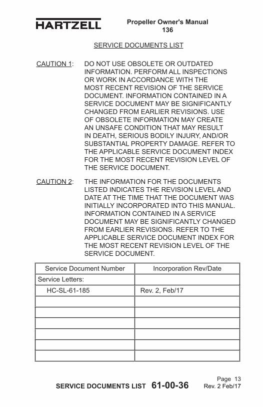
CAUTION 1: DO NOT USE OBSOLETE OR OUTDATED INFORMATION. PERFORM ALL INSPECTIONS OR WORK IN ACCORDANCE WITH THE MOST RECENT REVISION OF THE SERVICE DOCUMENT. INFORMATION CONTAINED IN A SERVICE DOCUMENT MAY BE SIGNIFICANTLY CHANGED FROM EARLIER REVISIONS. USE OF OBSOLETE INFORMATION MAY CREATE AN UNSAFE CONDITION THAT MAY RESULT IN DEATH, SERIOUS BODILY INJURY, AND/OR SUBSTANTIAL PROPERTY DAMAGE. REFER TO THE APPLICABLE SERVICE DOCUMENT INDEX FOR THE MOST RECENT REVISION LEVEL OF THE SERVICE DOCUMENT.
CAUTION 2: THE INFORMATION FOR THE DOCUMENTS LISTED INDICATES THE REVISION LEVEL AND DATE AT THE TIME THAT THE DOCUMENT WAS INITIALLY INCORPORATED INTO THIS MANUAL. INFORMATION CONTAINED IN A SERVICE DOCUMENT MAY BE SIGNIFICANTLY CHANGED FROM EARLIER REVISIONS. REFER TO THE APPLICABLE SERVICE DOCUMENT INDEX FOR THE MOST RECENT REVISION LEVEL OF THE SERVICE DOCUMENT.
Service Document Number Incorporation Rev/DateService Letters:
HC-SL-61-185 Rev. 2, Feb/17
Page 14 Rev. 2 Feb/17SERVICE DOCUMENTS LIST 61-00-36
Propeller Owner's Manual 136
(This page is intentionally blank.)
Propeller Owner's Manual 136
Page 15 Rev. 2 Feb/17AIRWORTHINESS LIMITATIONS 61-00-36
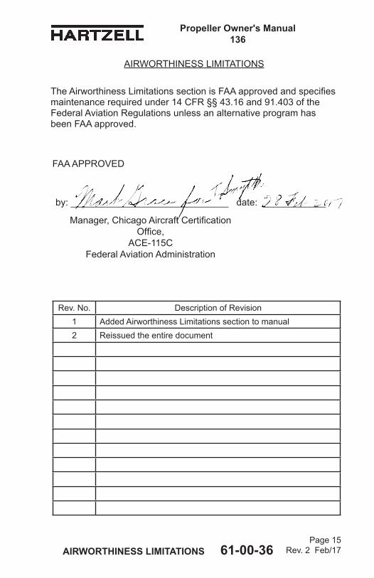
Rev. No. Description of Revision1 Added Airworthiness Limitations section to manual2 Reissued the entire document
AIRWORTHINESS LIMITATIONS
The Airworthiness Limitations section is FAA approved and specifies maintenance required under 14 CFR §§ 43.16 and 91.403 of the Federal Aviation Regulations unless an alternative program has been FAA approved.
FAA APPROVED
by: ______________________________ date: ____________
Manager, Chicago Aircraft Certification Office,
ACE-115CFederal Aviation Administration
Page 16 Rev. 2 Feb/17AIRWORTHINESS LIMITATIONS 61-00-36
Propeller Owner's Manual136
1. The FAA establishes specific life limits for certain component parts as well as the entire propeller. Such limits require replacement of the identified parts after a specified number of hours of use.
2. The following data summarizes all current information about Hartzell Propeller Inc. life limited parts that relate to propeller models affected by this manual. These parts are not life limited on other installations; however, time accumulated toward life limit accrues when first operated on aircraft/engine/propeller combinations listed and continues regardless of subsequent installations (that may or may not be life limited).A. Propeller models affected by this manual currently do not
have any life limited parts.B. There are no new (or additional) Airworthiness Limitations
associated with this equipment and/or installation.
AIRWORTHINESS LIMITATIONS
FAA APPROVED
by: ______________________________ date: ____________
Manager, Chicago Aircraft Certification Office,
ACE-115CFederal Aviation Administration
LIST OF EFFECTIVE PAGES
Propeller Owner's Manual 136
Chapter Page Revision Date
LIST OF EFFECTIVE PAGES 61-00-15Page 17
Rev. 2 Feb/17
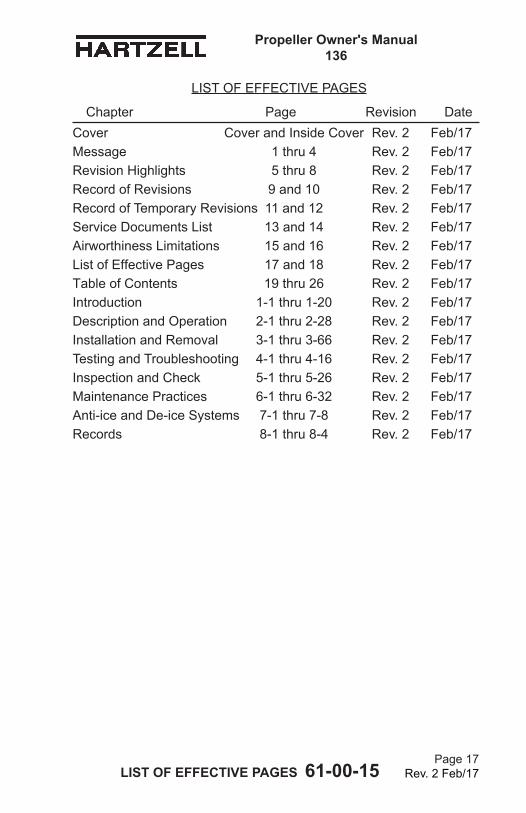
Cover Cover and Inside Cover Rev. 2 Feb/17Message 1 thru 4 Rev. 2 Feb/17Revision Highlights 5 thru 8 Rev. 2 Feb/17Record of Revisions 9 and 10 Rev. 2 Feb/17Record of Temporary Revisions 11 and 12 Rev. 2 Feb/17Service Documents List 13 and 14 Rev. 2 Feb/17Airworthiness Limitations 15 and 16 Rev. 2 Feb/17List of Effective Pages 17 and 18 Rev. 2 Feb/17Table of Contents 19 thru 26 Rev. 2 Feb/17Introduction 1-1 thru 1-20 Rev. 2 Feb/17Description and Operation 2-1 thru 2-28 Rev. 2 Feb/17Installation and Removal 3-1 thru 3-66 Rev. 2 Feb/17Testing and Troubleshooting 4-1 thru 4-16 Rev. 2 Feb/17Inspection and Check 5-1 thru 5-26 Rev. 2 Feb/17Maintenance Practices 6-1 thru 6-32 Rev. 2 Feb/17Anti-ice and De-ice Systems 7-1 thru 7-8 Rev. 2 Feb/17Records 8-1 thru 8-4 Rev. 2 Feb/17
LIST OF EFFECTIVE PAGES 61-00-36Page 18
Rev. 2 Feb/17
Propeller Owner's Manual 136
(This page is intentionally blank.)
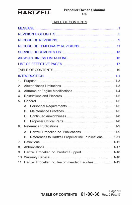
TABLE OF CONTENTS 61-00-36Page 19
Rev. 2 Feb/17
Propeller Owner's Manual 136
MESSAGE ..........................................................................................1
REVISION HIGHLIGHTS ...................................................................5
RECORD OF REVISIONS .................................................................9
RECORD OF TEMPORARY REVISIONS ........................................11
SERVICE DOCUMENTS LIST .........................................................13
AIRWORTHINESS LIMITATIONS ....................................................15
LIST OF EFFECTIVE PAGES ..........................................................17
TABLE OF CONTENTS ....................................................................19
INTRODUCTION ............................................................................ 1-11. Purpose .................................................................................... 1-32. Airworthiness Limitations ......................................................... 1-33. AirframeorEngineModifications ............................................. 1-44. RestrictionsandPlacards ........................................................ 1-55. General .................................................................................... 1-5
A. PersonnelRequirements ................................................... 1-5B. MaintenancePractices ...................................................... 1-5C. Continued Airworthiness .................................................... 1-8D. PropellerCriticalParts ....................................................... 1-8
6. ReferencePublications ............................................................ 1-9
A. HartzellPropellerInc.Publications .................................... 1-9B. ReferencestoHartzellPropellerInc.Publications ...........1-11
7. Definitions .............................................................................. 1-128. Abbreviations ......................................................................... 1-179. HartzellPropellerInc.ProductSupport .................................. 1-1810.WarrantyService .................................................................... 1-1811. HartzellPropellerInc.RecommendedFacilities .................... 1-19
TABLE OF CONTENTS
TABLE OF CONTENTS 61-00-36Page 20
Rev. 2 Feb/17
Propeller Owner's Manual 136
DESCRIPTION AND OPERATION ................................................. 2-11. DescriptionofPropellerandSystems ...................................... 2-6
A. GeneralOperationandSystemOverview ......................... 2-6B. PropellerandPressureControlUnitFeatures. ................... 2-7C. PropellerGovernedOperation ......................................... 2-10D. PropellerBeta(Reverse)Operation ................................ 2-12
2. PilotOperationofPropellerBladeAngleinBetaRange (LowPitchtoFullReversePitch)forManeuvering ................ 2-173. ModelDesignation ................................................................. 2-20
A. AluminumHubPropellerModelIdentification .................. 2-20B. AluminumBladeModelIdentification .............................. 2-21
4. Governors .............................................................................. 2-23A. Theory of Operation ......................................................... 2-23B. Governor Types ............................................................... 2-25C. IdentificationofHartzellPropellerInc.Governors ........... 2-25
5. PropellerIceProtectionSystems ........................................... 2-26A. PropellerAnti-iceSystem ................................................ 2-26B. PropellerDe-iceSystem .................................................. 2-27
INSTALLATION AND REMOVAL .................................................... 3-11. Tools,Consumables,andExpendables ................................... 3-5
A. Tooling ............................................................................... 3-5B. Consumables ..................................................................... 3-6C. Expendables ...................................................................... 3-6
2. Pre-Installation ......................................................................... 3-7A. InspectionofShippingPackage ........................................ 3-7B. Uncrating ........................................................................... 3-7C. InspectionafterShipment .................................................. 3-7D. ReassemblyofaPropellerDisassembledforShipment ... 3-7
3. SpinnerPre-Installation ...........................................................3-11A. General .............................................................................3-11B. InstallationofaMetalSpinnerBulkhead onaPropellerHub ............................................................3-14
TABLEOFCONTENTS,CONTINUED
TABLE OF CONTENTS 61-00-36Page 21
Rev. 2 Feb/17
Propeller Owner's Manual 136
C. InstallationofaCompositeSpinnerBulkheadona PropellerHub ....................................................................3-19D. Spinner Adapter Ring Unit toStarterRingGearInstallation ...................................... 3-23
4.PressureGaugeAttachmenttothePressureControlUnit ....... 3-295. PressureControlUnitandGovernorInstallation ................... 3-31
A. BeforeInstallation ............................................................ 3-31B. Preparing the Governor Mounting Pad on the Engine. .... 3-35C. InstallingthePressureControlUnitandtheGovernor .... 3-41D. PressureControlUnitAdjustment ................................... 3-43
6. PropellerInstallation .............................................................. 3-53A. FlangeDescription ........................................................... 3-53B. Installationof“R”FlangePropellers ................................ 3-53
7. SpinnerDomeInstallation ...................................................... 3-58A. General ............................................................................ 3-58B. InstallingtheSpinnerDome ............................................ 3-58
8. Post-InstallationChecks ........................................................ 3-599. PressureControlUnitandGovernorRemoval ...................... 3-6110.SpinnerRemoval ................................................................... 3-63
A. RemovaloftheSpinner ................................................... 3-63B. HubMountedSpinnerBulkheadRemoval ...................... 3-63
11. PropellerRemoval ................................................................. 3-64A. Removalof“R”FlangePropellers ................................... 3-64
TESTING AND TROUBLESHOOTING .......................................... 4-1
1. OperationalTests ..................................................................... 4-3A. General .............................................................................. 4-3B. InitialRun-UptoPurgeTrappedAir ................................... 4-3C. BetaRangeOperationCheck ............................................ 4-4D. GovernorOperationCheck ................................................ 4-4E. StaticRPMCheck ............................................................. 4-5F. OilLeakageCheck ............................................................ 4-6
TABLEOFCONTENTS,CONTINUED
TABLE OF CONTENTS 61-00-36Page 22
Rev. 2 Feb/17
Propeller Owner's Manual 136
2. PropellerIceProtectionSystems ............................................. 4-6A. ElectricDe-iceSystem ...................................................... 4-6B. Anti-iceSystem .................................................................. 4-6
3. Troubleshooting ....................................................................... 4-7A. Hunting and Surging .......................................................... 4-7B. Engine/PropellerSpeedVarieswithAirspeed ................... 4-8C. Engine/PropellerSpeedIncreasesWithIncreasing EnginePowerAndDecreasesWithDecreasing Engine Power .................................................................... 4-9D. GovernorRPMControlofEngine/PropellerSpeedHas LittleorNoEffect ............................................................... 4-9E. PropellerUnderspeed ...................................................... 4-10F. PropellerOverspeed .........................................................4-11G. Beta Range Operation ..................................................... 4-12H. Vibration .......................................................................... 4-13I. OilorGreaseLeakage .................................................... 4-15
INSPECTION AND CHECK ............................................................ 5-11. Pre-FlightChecks .................................................................... 5-32. OperationalChecks ................................................................. 5-53. RequiredPeriodicInspectionsandMaintenance ..................... 5-7
A. PeriodicInspections .......................................................... 5-7B. PeriodicMaintenance ........................................................ 5-8C. Airworthiness Limitations ................................................... 5-9D. OverhaulPeriods ............................................................. 5-10
4. InspectionProcedures ............................................................5-11A. BladeDamage ..................................................................5-11B. GreaseorOilLeakage .................................................... 5-12C. Vibration .......................................................................... 5-14D. TachometerInspection .................................................... 5-15E. BladeTrack ...................................................................... 5-17
TABLEOFCONTENTS,CONTINUED
TABLE OF CONTENTS 61-00-36Page 23
Rev. 2 Feb/17
Propeller Owner's Manual 136
F. LooseBlades ................................................................... 5-18G. Corrosion ......................................................................... 5-18H. Spinner Damage .............................................................. 5-19I. ElectricDe-iceSystem .................................................... 5-19J. Anti-iceSystem ................................................................ 5-19
5. SpecialInspections ................................................................ 5-21A. Overspeed ....................................................................... 5-21B. LightningStrike ................................................................ 5-22C. ForeignObjectStrike ....................................................... 5-23D. Fire Damage or Heat Damage ........................................ 5-25
6. Long Term Storage................................................................. 5-26
MAINTENANCE PRACTICES ........................................................ 6-1
1. Cleaning ................................................................................... 6-3A. GeneralCleaning ............................................................... 6-3B. SpinnerCleaningandPolishing ........................................ 6-4
2. Lubrication ............................................................................... 6-7A. LubricationIntervals .......................................................... 6-7B. LubricationProcedure ....................................................... 6-9C. ApprovedLubricants ........................................................ 6-12
3. BladeRepairs ........................................................................ 6-13A. RepairofNicksorGouges .............................................. 6-15B. RepairofBentBlades ...................................................... 6-17
4. Painting After Repair .............................................................. 6-19A. General ............................................................................ 6-19B. PaintingofAluminumBlades ........................................... 6-20
5. DynamicBalance ................................................................... 6-23A. Overview .......................................................................... 6-23B. InspectionProceduresBeforeBalancing ........................ 6-24C. ModifyingSpinnerBulkheadtoAccommodate DynamicBalanceWeights ............................................... 6-25D. PlacementofBalanceWeightsforDynamicBalance ..... 6-26
TABLEOFCONTENTS,CONTINUED
TABLE OF CONTENTS 61-00-36Page 24
Rev. 2 Feb/17
Propeller Owner's Manual 136
6. PropellerLowPitchSetting .................................................... 6-27A. LowPitch ......................................................................... 6-27
7. PropellerPitchSettings .......................................................... 6-29A. HighPitchStop ............................................................... 6-29B. LowPitchStop ................................................................ 6-29C. ReversePitchStop ......................................................... 6-29
8. PropellerIceProtectionSystems ........................................... 6-29A. ElectricDe-iceSystem .................................................... 6-29B. Anti-iceSystem ................................................................ 6-29
ANTI-ICE AND DE-ICE SYSTEMS ................................................ 7-11. Introduction .............................................................................. 7-3
A. PropellerDe-iceSystem .................................................... 7-3B. PropellerAnti-iceSystem .................................................. 7-3
2. SystemDescription .................................................................. 7-4A. De-iceSystem ................................................................... 7-4B. Anti-iceSystem .................................................................. 7-5
3. De-iceSystemOperationChecks ............................................ 7-64. Anti-iceSystemOperational/FunctionalChecks ...................... 7-65. De-iceandAnti-iceSystemInspections ................................... 7-7
A. De-iceSystemInspections ................................................ 7-7B. Anti-iceSystemInspections .............................................. 7-7
6. De-iceandAnti-iceSystemTroubleshooting ........................... 7-8A. De-iceSystemTroubleshooting ......................................... 7-8B. Anti-iceSystemTroubleshooting ....................................... 7-8
RECORDS ..................................................................................... 8-1
1. Introduction .............................................................................. 8-32. RecordKeeping ....................................................................... 8-3
A. InformationtobeRecorded ............................................... 8-3
TABLEOFCONTENTS,CONTINUED
TABLE OF CONTENTS 61-00-36Page 25
Rev. 2 Feb/17
Propeller Owner's Manual 136
LIST OF FIGURES
-7 Series Constant Speed and Reversing PropellerHC-E3YR-7() ............................. Figure 2-1 ........... 2-3
PressureControlReversingPropeller System .......................................................Figure 2-2 ............ 2-4
OilPressures-PressureControl ReversingPropeller ................................... Figure 2-3 ............ 2-5
PressureControlUnit ....................................... Figure 2-4 ............ 2-8
Governor in Onspeed Condition ....................... Figure 2-5 .......... 2-22
Governor in Underspeed Condition .................. Figure 2-6 .......... 2-22
Governor in Overspeed Condition .................... Figure 2-7 .......... 2-22
Synchronizer/SynchrophaserGovernor ........... Figure 2-8 .......... 2-24
DeterminingTorqueValue WhenUsingTorquingAdapter ................... Figure 3-1 ............ 3-8
HubClampingBoltLocation for Spinner Mounting .................................. Figure 3-2 .......... 3-10
MetalSpinnerBulkheadandSpinner Mounting(HubMountedSpinner) .............. Figure 3-3 .......... 3-12
SpinnerInstallationClearance.......................... Figure 3-4 .......... 3-13
CompositeBulkheadandSpinner Mounting(HubMountedSpinner) .............. Figure 3-5 .......... 3-18
Spinner Adapter and Spinner Mounting(StarterRingGearMount) .......... Figure 3-6 .......... 3-22
SamplePressureControlUnit .......................... Figure 3-7 .......... 3-25
SampleGovernorUnitandPressure ControlUnitInstalledontheEngine .......... Figure 3-8 .......... 3-26
A-3147-3 Stud ..................................................Figure 3-9 .......... 3-27
B-1104GovernorGasket .................................. Figure 3-10 ........ 3-27
SampleofaPressureControlUnit andPressureGaugeAttachment ............... Figure 3-11 ........ 3-28
A-3144-2GovernorDriveExtension................. Figure 3-12 ........ 3-30
TABLE OF CONTENTS 61-00-36Page 26
Rev. 2 Feb/17
Propeller Owner's Manual 136
LIST OF TABLES
TorqueTable .....................................................Table3-1 ............. 3-9
MetalSpinnerBulkheadMountingHardware ...Table3-2 ........... 3-16
CompositeSpinnerBulkhead Mounting Hardware ....................................Table3-3 ........... 3-20
Propeller/EngineFlangeO-rings and Mounting Hardware .............................Table3-4 .......... 3-54
ApprovedTouch-upPaints ...............................Table6-1 ........... 6-18
GovernorMountingPadWithStudsInstalled... Figure 3-13 ........ 3-34
PressureControlComponents -FieldSupplied .......................................... Figure 3-14 ........ 3-38
PressureControlComponents -HartzellPropellerInc.Supplied ............... Figure 3-15 ........ 3-39
OilPressuresforPressureUnitAdjustment ..... Figure 3-16 ........ 3-40
“R”FlangePropellerMounting ......................... Figure 3-17 ........ 3-52
DiagramofTorquingSequence forPropellerMountingHardware .............. Figure 3-18 ........ 3-56
CheckingBladeTrack....................................... Figure 5-1 ......... 5-16
BladePlay ........................................................Figure 5-2 .......... 5-16
ReciprocatingEngineOverspeedLimits .......... Figure 5-3 .......... 5-20
LubricationFittingLocation............................... Figure 6-1 ............ 6-6
LubricationFitting .............................................Figure 6-2 ............ 6-8
LubricationLabel ..............................................Figure 6-3 .......... 6-10
Repair Limitations .............................................Figure 6-4 .......... 6-14
LISTOFFIGURES,CONTINUED
Propeller Owner's Manual 136
INTRODUCTION 61-00-36 Page 1-1
Rev. 2 Feb/17
INTRODUCTION - CONTENTS
1. Purpose ....................................................................................1-3
2. Airworthiness Limitations .........................................................1-3
3. AirframeorEngineModifications .............................................1-4
4. RestrictionsandPlacards ........................................................1-5
5. General ....................................................................................1-5A. PersonnelRequirements ...................................................1-5B. MaintenancePractices ......................................................1-5C. Continued Airworthiness ....................................................1-8D. PropellerCriticalParts .......................................................1-8
6. ReferencePublications ............................................................1-9
A. HartzellPropellerInc.Publications ....................................1-9B. ReferencestoHartzellPropellerInc.Publications .......... 1-11
7. Definitions ..............................................................................1-12
8. Abbreviations .........................................................................1-17
9. HartzellPropellerInc.ProductSupport ..................................1-18
10.WarrantyService ....................................................................1-18
11. HartzellPropellerInc.RecommendedFacilities ....................1-19
Propeller Owner's Manual 136
INTRODUCTION 61-00-36 Page 1-2
Rev. 2 Feb/17
(Thispageisintentionallyblank.)
Propeller Owner's Manual 136
INTRODUCTION 61-00-36 Page 1-3
Rev. 2 Feb/17
1. PurposeA. ThismanualhasbeenreviewedandacceptedbytheFAA.
Additionally,theAirworthinessLimitationsSectionofthismanualhasbeenapprovedbytheFAA.
CAUTION: KEEP THIS MANUAL WITH THE PROPELLER OR THE AIRCRAFT UPON WHICH IT IS INSTALLED AT ALL TIMES. THE LOGBOOK RECORD WITHIN THIS MANUAL MUST BE MAINTAINED,RETAINEDCONCURRENTLY,AND BECOME A PART OF THE AIRCRAFT AND ENGINE SERVICE RECORDS.
B. ThismanualsupportsHartzellPropellerInc.ConstantSpeed,ReversingHC-E3YR-7()compactpropellerswithaluminumblades.
C. Thepurposeofthismanualistoenablequalifiedpersonneltoinstall,operate,andmaintainaHartzellPropellerInc.HC-E3YR-7()propeller.Separatemanualsareavailableconcerningoverhaulproceduresandspecificationsforthepropeller.
D. ThismanualincludestheHC-E3YR-7()design.SamplehubandblademodelnumberswithinthisdesignarecoveredintheDescriptionandOperationChapterofthismanual.NOTE: Allpropellermodelscoveredbythismanualuse
aluminumpropellerblades.
2. Airworthiness LimitationsA. RefertotheAirworthinessLimitationschapterofthismanual
for Airworthiness Limits information.
Propeller Owner's Manual 136
INTRODUCTION 61-00-36 Page 1-4
Rev. 2 Feb/17
3. AirframeorEngineModificationsA. Propellersareapprovedvibrationwiseonairframeand
enginecombinationsbasedontestsoranalysisofsimilarinstallations.Thisdatahasdemonstratedthatpropellerstresslevelsareaffectedbyairframeconfiguration,airspeed,weight,power,engineconfigurationandapprovedflightmaneuvers.Aircraftmodificationsthatcaneffectpropellerstressinclude,butarenotlimitedto:aerodynamicchangesaheadoforbehindthepropeller,realignmentofthethrustaxis,increasingordecreasingairspeedlimits,increasingordecreasingweightlimits(lesssignificantonpistonengines),theadditionofapprovedflightmaneuvers(utilityandaerobatic).
B. Enginemodificationscanalsoaffectthepropeller.Thetwoprimarycategoriesofenginemodificationsarethosethataffectstructureandthosethataffectpower.Anexampleofastructuralenginemodificationisthealterationofthecrankshaftordamperofapistonengine.Anychangetotheweight,stiffnessortuningofrotatingcomponentscouldresultinapotentiallydangerousresonantconditionthatisnotdetectablebythepilot.Mostcommonenginemodificationsaffectthepowerduringsomephaseofoperation.Somemodificationsincreasethemaximumpoweroutput,whileothersimprovethepoweravailableduringhotandhighoperation(flatrating)oratoff-peakconditions.Examplesofsuchenginemodificationsinclude,butarenotlimitedto:changestothecompressor,powerturbineorhotsectionofaturbopropengine;andonpistonengines,theadditionoralterationofaturbochargerorturbonormalizer,increasedcompressionratio,increasedrpm,alteredignitiontiming,electronicignition,fullauthoritydigitalelectroniccontrols(FADEC),ortunedinductionorexhaust.
C. Allsuchmodificationsmustbereviewedandapprovedbythepropellermanufacturerbeforeobtainingapprovalontheaircraft.
Propeller Owner's Manual 136
INTRODUCTION 61-00-36 Page 1-5
Rev. 2 Feb/17
4. RestrictionsandPlacardsA. Thepropellersincludedinthismanualmayhavearestricted
operatingrangethatrequiresacockpitplacard.(1) Therestrictions,ifpresent,willvarydependingonthe
propeller,blade,engine,and/oraircraftmodel.(2) Reviewthepropellerandaircrafttypecertificatedata
sheet(TCDS),PilotOperatingHandbook(POH),andanyapplicableAirworthinessDirectivesforspecificinformation.
5. GeneralA. PersonnelRequirements
(1) Inspection,Repair,andOverhaul(a) Compliancetotheapplicableregulatory
requirementsestablishedbytheFederalAviationAdministration(FAA)orforeignequivalentismandatoryforanyoneperformingoracceptingresponsibilityforanyinspectionand/orrepairand/oroverhaulofanyHartzellPropellerInc.product.
(b) Personnelperformingmaintenanceonsteelhubpropellersareexpectedtohavesufficienttrainingandcertifications(whenrequiredbytheapplicableAviationAuthority)toaccomplishtheworkrequiredinasafeand airworthy manner.
B. MaintenancePractices(1) Thepropelleranditscomponentsarehighlyvulnerable
todamagewhiletheyareremovedfromtheengine.Properlyprotectallcomponentsuntiltheyarereinstalledon the engine.
(2) Neverattempttomovetheaircraftbypullingonthepropeller.
(3) Avoidtheuseofbladepaddles.Ifbladepaddlesmustbeused,useatleasttwopaddles.Donotputthebladepaddleintheareaofthede-iceoranti-icingbootwhenapplyingtorquetoabladeassembly.Putthebladepaddleinthethickestareaoftheblade,justoutsideofthede-iceoranti-icingboot.Useonebladepaddleperblade.
(4) Useonlytheapprovedconsumables,e.g.,cleaningagents,lubricants,etc.
Propeller Owner's Manual 136
INTRODUCTION 61-00-36 Page 1-6
Rev. 2 Feb/17
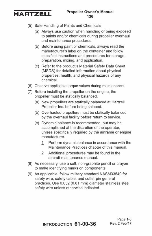
(5) SafeHandlingofPaintsandChemicals(a) Alwaysusecautionwhenhandlingorbeingexposed
topaintsand/orchemicalsduringpropelleroverhaulandmaintenanceprocedures.
(b) Beforeusingpaintorchemicals,alwaysreadthemanufacturer’slabelonthecontainerandfollowspecifiedinstructionsandproceduresforstorage,preparation,mixing,andapplication.
(c) Refertotheproduct’sMaterialSafetyDataSheet(MSDS)fordetailedinformationaboutphysicalproperties,health,andphysicalhazardsofanychemical.
(6) Observeapplicabletorquevaluesduringmaintenance.(7) Beforeinstallingthepropellerontheengine,the
propellermustbestaticallybalanced.(a) NewpropellersarestaticallybalancedatHartzell
PropellerInc.beforebeingshipped.(b) Overhauledpropellersmustbestaticallybalanced
bytheoverhaulfacilitybeforereturntoservice.(c) Dynamicbalanceisrecommended,butmaybe
accomplishedatthediscretionoftheoperator,unlessspecificallyrequiredbytheairframeorenginemanufacturer.1 Performdynamicbalanceinaccordancewiththe
MaintenancePracticeschapterofthismanual.2 Additionalproceduresmaybefoundinthe
aircraftmaintenancemanual.(8) Asnecessary,useasoft,non-graphitepencilorcrayon
tomakeidentifyingmarksoncomponents.(9) Asapplicable,followmilitarystandardNASM33540for
safetywire,safetycable,andcotterpingeneralpractices.Use0.032(0.81mm)diameterstainlesssteelsafetywireunlessotherwiseindicated.
Propeller Owner's Manual 136
INTRODUCTION 61-00-36 Page 1-7
Rev. 2 Feb/17
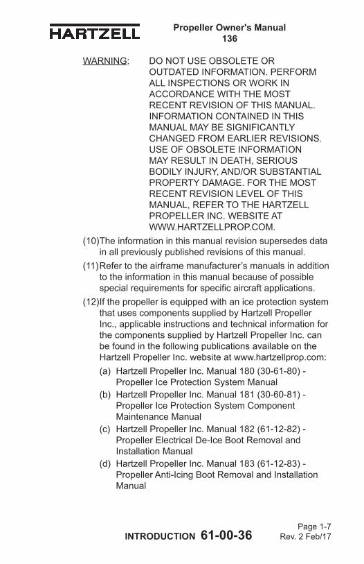
WARNING: DO NOT USE OBSOLETE OR OUTDATED INFORMATION. PERFORM ALL INSPECTIONS OR WORK IN ACCORDANCE WITH THE MOST RECENT REVISION OF THIS MANUAL. INFORMATION CONTAINED IN THIS MANUALMAYBESIGNIFICANTLYCHANGED FROM EARLIER REVISIONS. USE OF OBSOLETE INFORMATION MAYRESULTINDEATH,SERIOUSBODILYINJURY,AND/ORSUBSTANTIALPROPERTYDAMAGE.FOR THE MOST RECENT REVISION LEVEL OF THIS MANUAL,REFERTOTHEHARTZELLPROPELLER INC. WEBSITE AT WWW.HARTZELLPROP.COM.
(10)Theinformationinthismanualrevisionsupersedesdatainallpreviouslypublishedrevisionsofthismanual.
(11)Refertotheairframemanufacturer’smanualsinaddition totheinformationinthismanualbecauseofpossiblespecialrequirementsforspecificaircraftapplications.
(12)IfthepropellerisequippedwithaniceprotectionsystemthatusescomponentssuppliedbyHartzellPropellerInc.,applicableinstructionsandtechnicalinformationforthecomponentssuppliedbyHartzellPropellerInc.canbefoundinthefollowingpublicationsavailableontheHartzellPropellerInc.websiteatwww.hartzellprop.com:(a) HartzellPropellerInc.Manual180(30-61-80)-
PropellerIceProtectionSystemManual(b) HartzellPropellerInc.Manual181(30-60-81)-
PropellerIceProtectionSystemComponentMaintenanceManual
(c) HartzellPropellerInc.Manual182(61-12-82)- PropellerElectricalDe-IceBootRemovalandInstallationManual
(d) HartzellPropellerInc.Manual183(61-12-83)-PropellerAnti-IcingBootRemovalandInstallationManual
Propeller Owner's Manual 136
INTRODUCTION 61-00-36 Page 1-8
Rev. 2 Feb/17
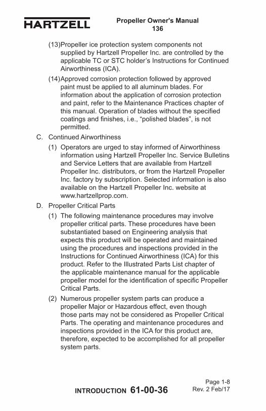
(13)PropellericeprotectionsystemcomponentsnotsuppliedbyHartzellPropellerInc.arecontrolledbytheapplicableTCorSTCholder’sInstructionsforContinuedAirworthiness(ICA).
(14)Approvedcorrosionprotectionfollowedbyapprovedpaintmustbeappliedtoallaluminumblades.Forinformationabouttheapplicationofcorrosionprotectionandpaint,refertotheMaintenancePracticeschapterofthismanual.Operationofbladeswithoutthespecifiedcoatingsandfinishes,i.e.,“polishedblades”,isnotpermitted.
C. Continued Airworthiness(1) OperatorsareurgedtostayinformedofAirworthiness
informationusingHartzellPropellerInc.ServiceBulletinsandServiceLettersthatareavailablefromHartzellPropellerInc.distributors,orfromtheHartzellPropellerInc.factorybysubscription.SelectedinformationisalsoavailableontheHartzellPropellerInc.websiteat www.hartzellprop.com.
D. PropellerCriticalParts(1) Thefollowingmaintenanceproceduresmayinvolve
propellercriticalparts.TheseprocedureshavebeensubstantiatedbasedonEngineeringanalysisthatexpectsthisproductwillbeoperatedandmaintainedusingtheproceduresandinspectionsprovidedintheInstructionsforContinuedAirworthiness(ICA)forthisproduct.RefertotheIllustratedPartsListchapteroftheapplicablemaintenancemanualfortheapplicablepropellermodelfortheidentificationofspecificPropellerCriticalParts.
(2) NumerouspropellersystempartscanproduceapropellerMajororHazardouseffect,eventhoughthosepartsmaynotbeconsideredasPropellerCriticalParts.TheoperatingandmaintenanceproceduresandinspectionsprovidedintheICAforthisproductare,therefore,expectedtobeaccomplishedforallpropellersystem parts.
Propeller Owner's Manual 136
INTRODUCTION 61-00-36 Page 1-9
Rev. 2 Feb/17
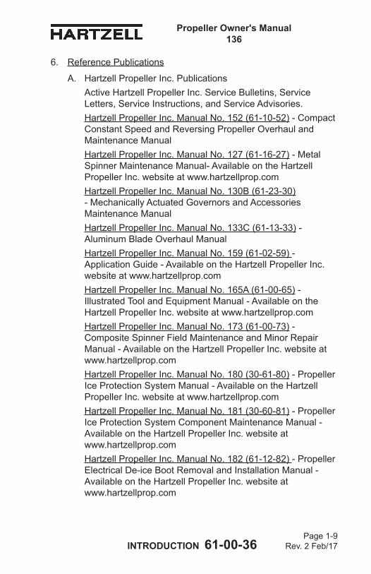
6. ReferencePublications
A. HartzellPropellerInc.PublicationsActiveHartzellPropellerInc.ServiceBulletins,ServiceLetters,ServiceInstructions,andServiceAdvisories.HartzellPropellerInc.ManualNo.152(61-10-52)-CompactConstantSpeedandReversingPropellerOverhaulandMaintenanceManualHartzellPropellerInc.ManualNo.127(61-16-27)-MetalSpinnerMaintenanceManual-AvailableontheHartzellPropellerInc.websiteatwww.hartzellprop.comHartzellPropellerInc.ManualNo.130B(61-23-30) -MechanicallyActuatedGovernorsandAccessoriesMaintenanceManualHartzellPropellerInc.ManualNo.133C(61-13-33) - AluminumBladeOverhaulManualHartzellPropellerInc.ManualNo.159(61-02-59)- ApplicationGuide-AvailableontheHartzellPropellerInc.websiteatwww.hartzellprop.comHartzellPropellerInc.ManualNo.165A(61-00-65) - IllustratedToolandEquipmentManual-AvailableontheHartzellPropellerInc.websiteatwww.hartzellprop.comHartzellPropellerInc.ManualNo.173(61-00-73) - CompositeSpinnerFieldMaintenanceandMinorRepairManual-AvailableontheHartzellPropellerInc.websiteatwww.hartzellprop.comHartzellPropellerInc.ManualNo.180(30-61-80)-PropellerIceProtectionSystemManual-AvailableontheHartzellPropellerInc.websiteatwww.hartzellprop.comHartzellPropellerInc.ManualNo.181(30-60-81)-PropellerIceProtectionSystemComponentMaintenanceManual-AvailableontheHartzellPropellerInc.websiteat www.hartzellprop.comHartzellPropellerInc.ManualNo.182(61-12-82)-PropellerElectricalDe-iceBootRemovalandInstallationManual-AvailableontheHartzellPropellerInc.websiteat www.hartzellprop.com
Propeller Owner's Manual 136
INTRODUCTION 61-00-36 Page 1-10
Rev. 2 Feb/17
HartzellPropellerInc.ManualNo.183(61-12-83)-PropellerAnti-icingBootRemovalandInstallationManual- AvailableontheHartzellPropellerInc.websiteat www.hartzellprop.comHartzellPropellerInc.ManualNo.202A(61-01-02) - StandardPracticesManual,Volumes1through11 (Volume7,ConsumableMaterialsandPackagingandStorageisavailableontheHartzellPropellerInc.website atwww.hartzellprop.com)HartzellPropellerInc.ServiceLetterHC-SL-61-61Y - OverhaulPeriodsandServiceLifeLimitsforHartzellPropellerInc.AviationComponents-Propellers,Governors,Accumulators,andPropellerDamperAssemblies-AvailableontheHartzellPropellerInc.websiteatwww.hartzellprop.com
Propeller Owner's Manual 136
INTRODUCTION 61-00-36 Page 1-11
Rev. 2 Feb/17
B. ReferencestoHartzellPropellerInc.PublicationsNOTE: SpecificHartzellPropellerInc.manualsand
servicedocumentsareavailableontheHartzellPropellerInc.websiteatwww.hartzellprop.com.Refertothesection“RequiredPublications”inthischapterfortheidentificationofthesepublications.
(1) Specialtoolingisrequiredforproceduresthroughout thismanual.Forfurthertoolinginformation,refertoHartzellPropellerInc.IllustratedToolandEquipmentManual165A(61-00-65).(a) Toolingreferencesappearwiththeprefix“TE”
directlyfollowingthetoolnametowhichthey apply.Forexample,atemplatewhichisreferencenumber133willappearas:templateTE133.
(2) Consumablematerialsarereferencedincertain sectionsthroughoutthismanual.SpecificapprovedmaterialsarelistedintheConsumableMaterials chapterofHartzellPropellerInc.StandardPracticesManual202A(61-01-02),Volume7ontheHartzellPropellerInc.website.(a) Thereferencenumberforconsumablematerials
appearwiththeprefix“CM”directlyfollowingthematerialtowhichtheyapply.Forexample,anapprovedadhesivethatisreferencenumber16willappearas:approvedadhesiveCM16.Onlythoseitemsspecifiedmaybeused.
Propeller Owner's Manual 136
INTRODUCTION 61-00-36 Page 1-12
Rev. 2 Feb/17
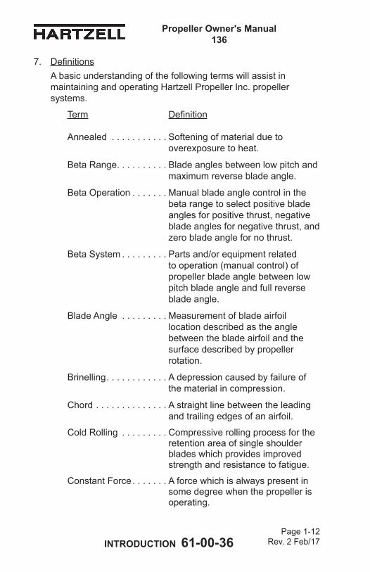
7. DefinitionsAbasicunderstandingofthefollowingtermswillassistinmaintainingandoperatingHartzellPropellerInc.propellersystems.
Term Definition
Annealed . . . . . . . . . . . Softeningofmaterialduetooverexposuretoheat.
Beta Range . . . . . . . . . . Bladeanglesbetweenlowpitchandmaximumreversebladeangle.
Beta Operation . . . . . . . Manualbladeanglecontrolinthebetarangetoselectpositivebladeanglesforpositivethrust,negativebladeanglesfornegativethrust,andzerobladeanglefornothrust.
Beta System . . . . . . . . . Partsand/orequipmentrelatedtooperation(manualcontrol)ofpropellerbladeanglebetweenlowpitchbladeangleandfullreversebladeangle.
BladeAngle . . . . . . . . . Measurementofbladeairfoillocationdescribedastheanglebetweenthebladeairfoilandthesurfacedescribedbypropellerrotation.
Brinelling . . . . . . . . . . . . Adepressioncausedbyfailureofthematerialincompression.
Chord . . . . . . . . . . . . . . Astraightlinebetweentheleadingandtrailingedgesofanairfoil.
ColdRolling . . . . . . . . . Compressiverollingprocessfortheretentionareaofsingleshoulderbladeswhichprovidesimprovedstrengthandresistancetofatigue.
ConstantForce . . . . . . . Aforcewhichisalwayspresentinsomedegreewhenthepropellerisoperating.
Propeller Owner's Manual 136
INTRODUCTION 61-00-36 Page 1-13
Rev. 2 Feb/17
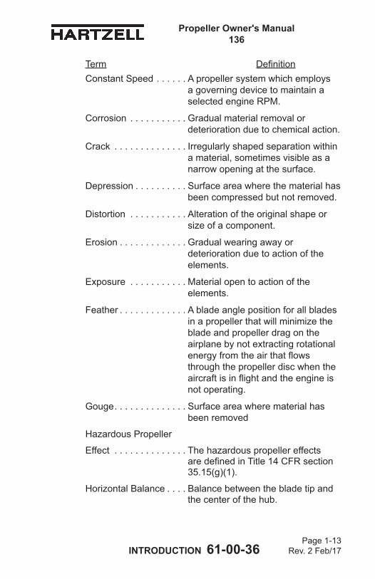
Constant Speed . . . . . . ApropellersystemwhichemploysagoverningdevicetomaintainaselectedengineRPM.
Corrosion . . . . . . . . . . . Gradualmaterialremovalordeteriorationduetochemicalaction.
Crack . . . . . . . . . . . . . . Irregularlyshapedseparationwithinamaterial,sometimesvisibleasanarrowopeningatthesurface.
Depression . . . . . . . . . . Surfaceareawherethematerialhasbeencompressedbutnotremoved.
Distortion . . . . . . . . . . . Alterationoftheoriginalshapeorsizeofacomponent.
Erosion . . . . . . . . . . . . . Gradualwearingawayordeteriorationduetoactionoftheelements.
Exposure . . . . . . . . . . . Materialopentoactionoftheelements.
Feather . . . . . . . . . . . . . Abladeanglepositionforallbladesinapropellerthatwillminimizethebladeandpropellerdragontheairplanebynotextractingrotationalenergyfromtheairthatflowsthroughthepropellerdiscwhentheaircraftisinflightandtheengineisnot operating.
Gouge . . . . . . . . . . . . . . Surfaceareawherematerialhasbeen removed
HazardousPropeller
Effect . . . . . . . . . . . . . . ThehazardouspropellereffectsaredefinedinTitle14CFRsection35.15(g)(1).
HorizontalBalance . . . . Balancebetweenthebladetipandthecenterofthehub.
Term Definition
Propeller Owner's Manual 136
INTRODUCTION 61-00-36 Page 1-14
Rev. 2 Feb/17
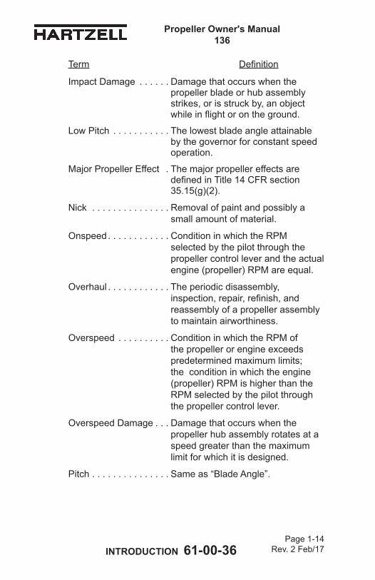
ImpactDamage . . . . . . Damagethatoccurswhenthepropellerbladeorhubassemblystrikes,orisstruckby,anobjectwhileinflightorontheground.
LowPitch . . . . . . . . . . . Thelowestbladeangleattainablebythegovernorforconstantspeedoperation.
MajorPropellerEffect . ThemajorpropellereffectsaredefinedinTitle14CFRsection35.15(g)(2).
Nick . . . . . . . . . . . . . . . Removalofpaintandpossiblyasmallamountofmaterial.
Onspeed . . . . . . . . . . . . ConditioninwhichtheRPMselectedbythepilotthroughthepropellercontrolleverandtheactualengine(propeller)RPMareequal.
Overhaul . . . . . . . . . . . . Theperiodicdisassembly,inspection,repair,refinish,andreassemblyofapropellerassemblyto maintain airworthiness.
Overspeed . . . . . . . . . . ConditioninwhichtheRPMofthepropellerorengineexceedspredeterminedmaximumlimits;theconditioninwhichtheengine(propeller)RPMishigherthantheRPMselectedbythepilotthroughthepropellercontrollever.
Overspeed Damage . . . Damagethatoccurswhenthe propellerhubassemblyrotatesataspeedgreaterthanthemaximum limitforwhichitisdesigned.
Pitch . . . . . . . . . . . . . . . Sameas“BladeAngle”.
Term Definition
Propeller Owner's Manual 136
INTRODUCTION 61-00-36 Page 1-15
Rev. 2 Feb/17
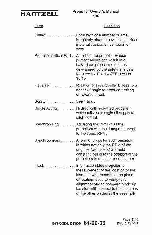
Pitting . . . . . . . . . . . . . . Formationofanumberofsmall,irregularlyshapedcavitiesinsurfacematerialcausedbycorrosionorwear.
PropellerCriticalPart . . Apartonthepropellerwhoseprimaryfailurecanresultinahazardouspropellereffect,asdeterminedbythesafetyanalysisrequiredbyTitle14CFRsection35.15.
Reverse . . . . . . . . . . . . Rotationofthepropellerbladestoanegativeangletoproducebrakingor reverse thrust.
Scratch . . . . . . . . . . . . . See“Nick”.
SingleActing . . . . . . . . . Hydraulicallyactuatedpropeller whichutilizesasingleoilsupplyforpitchcontrol.
Synchronizing . . . . . . . . AdjustingtheRPMofallthepropellersofamulti-engineaircraftto the same RPM.
Synchrophasing . . . . . . AformofpropellersychronizationinwhichnotonlytheRPMoftheengines(propellers)areheldconstant,butalsothepositionofthepropellersinrelationtoeachother.
Track . . . . . . . . . . . . . . . Inanassembledpropeller,ameasurementofthelocationofthebladetipwithrespecttotheplane ofrotation,usedtoverifyfacealignmentandtocomparebladetiplocationwithrespecttothelocationsoftheotherbladesintheassembly.
Term Definition
Propeller Owner's Manual 136
INTRODUCTION 61-00-36 Page 1-16
Rev. 2 Feb/17
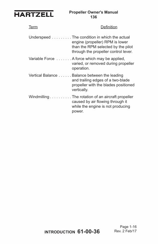
Underspeed . . . . . . . . . Theconditioninwhichtheactualengine(propeller)RPMislowerthantheRPMselectedbythepilot throughthepropellercontrollever.
VariableForce . . . . . . . Aforcewhichmaybeapplied,varied,orremovedduringpropelleroperation.
VerticalBalance . . . . . . Balancebetweentheleadingandtrailingedgesofatwo-bladepropellerwiththebladespositionedvertically.
Windmilling . . . . . . . . . . Therotationofanaircraftpropellercausedbyairflowingthroughitwhiletheengineisnotproducingpower.
Term Definition
Propeller Owner's Manual 136
INTRODUCTION 61-00-36 Page 1-17
Rev. 2 Feb/17
8. Abbreviations
Abbreviation Term
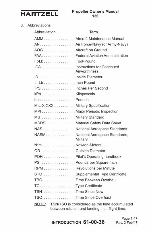
AMM . . . . . . . . . . . . . . . AircraftMaintenanceManualAN . . . . . . . . . . . . . . . . . AirForce-Navy(orArmy-Navy)AOG . . . . . . . . . . . . . . . AircraftonGroundFAA . . . . . . . . . . . . . . . . FederalAviationAdministrationFt-Lb . . . . . . . . . . . . . . . Foot-PoundICA . . . . . . . . . . . . . . . . InstructionsforContinued
AirworthinessID . . . . . . . . . . . . . . . . . Inside DiameterIn-Lb . . . . . . . . . . . . . . . Inch-PoundIPS . . . . . . . . . . . . . . . . InchesPerSecondkPa . . . . . . . . . . . . . . . . KilopascalsLbs . . . . . . . . . . . . . . . . Pounds MIL-X-XXX . . . . . . . . . . MilitarySpecificationMPI . . . . . . . . . . . . . . . . MajorPeriodicInspectionMS . . . . . . . . . . . . . . . . MilitaryStandardMSDS . . . . . . . . . . . . . . MaterialSafetyDataSheetNAS . . . . . . . . . . . . . . . NationalAerospaceStandardsNASM . . . . . . . . . . . . . . NationalAerospaceStandards,
MilitaryN•m . . . . . . . . . . . . . . . . Newton-MetersOD . . . . . . . . . . . . . . . . Outside DiameterPOH . . . . . . . . . . . . . . . Pilot’sOperatinghandbookPSI . . . . . . . . . . . . . . . . PoundsperSquareInchRPM . . . . . . . . . . . . . . . RevolutionsperMinuteSTC . . . . . . . . . . . . . . . SupplementalTypeCertificateTBO . . . . . . . . . . . . . . . TimeBetweenOverhaulTC . . . . . . . . . . . . . . . . . TypeCertificateTSN . . . . . . . . . . . . . . . TimeSinceNewTSO . . . . . . . . . . . . . . . TimeSinceOverhaul
NOTE: TSN/TSOisconsideredasthetimeaccumulatedbetweenrotationandlanding,i.e.,flighttime.
Propeller Owner's Manual 136
INTRODUCTION 61-00-36 Page 1-18
Rev. 2 Feb/17
9. HartzellPropellerInc.ProductSupportA. HartzellPropellerInc.isreadytoassistyouwithquestions
concerningyourpropellersystem.HartzellPropellerInc.ProductSupportmaybereachedduringbusinesshours(8:00amthrough5:00pm,UnitedStatesEasternTime)at (937)778-4379orat(800)942-7767,tollfreefromtheUnitedStatesandCanada.HartzellPropellerInc.ProductSupportcanalsobereachedbyfaxat(937)778-4215,[email protected].
B. Afterbusinesshours,youmayleaveamessageonour 24hourproductsupportlineat(937)778-4376orat (800)942-7767,tollfreefromtheUnitedStatesandCanada.Atechnicalrepresentativewillcontactyouduringnormalbusinesshours.UrgentAOGsupportisavailable24hoursperday,sevendaysperweekviathismessageservice.
C. Additionalinformationisavailableonourwebsiteat www.hartzellprop.com.
NOTE: WhencallingfromoutsidetheUnitedStates,dial(001)beforedialingtheabovetelephonenumbers.
10. WarrantyServiceA. Ifyoubelieveyouhaveawarrantyclaim,itisnecessaryto
contacttheHartzellPropellerInc.WarrantyAdministrator.TheWarrantyAdministratorwillprovideablankWarranty Applicationform.ItisnecessarytocompletethisformandreturnittotheWarrantyAdministratorforevaluationbefore proceeding with repair or inspection work. Upon receiptofthisform,theWarrantyAdministratorwillprovideinstructionsonhowtoproceed.HartzellPropellerInc.Warrantymaybereachedduringbusinesshours (8:00am.through5:00pm.,UnitedStatesEasternTime)at(937)778-4379,ortollfreefromtheUnitedStatesandCanadaat(800)942-7767.HartzellPropellerInc. WarrantyAdministrationcanalsobereachedbyfax,at (937)778-4215,[email protected]: WhencallingfromoutsidetheUnitedStates,dial
(001)beforedialingtheabovetelephonenumbers.
Propeller Owner's Manual 136
INTRODUCTION 61-00-36 Page 1-19
Rev. 2 Feb/17
11. HartzellPropellerInc.RecommendedFacilitiesA. HartzellPropellerInc.recommendsusingHartzell
PropellerInc.approveddistributorsandrepairfacilitiesforthepurchase,repairandoverhaulofHartzellPropellerInc.propellerassembliesorcomponents.
B. InformationabouttheHartzellPropellerInc.worldwidenetworkofaftermarketdistributorsandapprovedrepairfacilitiesisavailableontheHartzellPropellerInc.websiteat www.hartzellprop.com.
Propeller Owner's Manual 136
INTRODUCTION 61-00-36 Page 1-20
Rev. 2 Feb/17
(Thispageisintentionallyblank.)
Propeller Owner's Manual 136
DESCRIPTION AND OPERATION 61-00-36 Page 2-1
Rev. 2 Feb/17
DESCRIPTION AND OPERATION - CONTENTS
1. Description of Propeller and Systems ......................................2-6A. General Operation and System Overview .........................2-6B. Propeller and Pressure Control Unit Features. ...................2-7C. Propeller Governed Operation .........................................2-10D. Propeller Beta (Reverse) Operation ................................2-12
2. Pilot Operation of Propeller Blade Angle in Beta Range (Low Pitch to Full Reverse Pitch) for Maneuvering ................2-17
3. Model Designation .................................................................2-20A. AluminumHubPropellerModelIdentification ..................2-20B. AluminumBladeModelIdentification ..............................2-21
4. Governors ..............................................................................2-23A. Theory of Operation .........................................................2-23B. Governor Types ...............................................................2-25C. IdentificationofHartzellPropellerInc.Governors ...........2-25
5. Propeller Ice Protection Systems ...........................................2-26A. Propeller Anti-ice System ................................................2-26B. Propeller De-ice System ..................................................2-27
Propeller Owner's Manual 136
DESCRIPTION AND OPERATION 61-00-36 Page 2-2
Rev. 2 Feb/17
LIST OF FIGURES-7 Series Constant Speed and Reversing
Propeller HC-E3YR-7( ) ........................... Figure 2-1 .............2-3
Pressure Control Reversing Propeller System ..................................................... Figure 2-2 ..............2-4
Oil Pressures - Pressure Control Reversing Propeller ................................. Figure 2-3 ..............2-5
Pressure Control Unit ..................................... Figure 2-4 ..............2-8
Governor in Onspeed Condition ..................... Figure 2-5 ............2-22
Governor in Underspeed Condition ................ Figure 2-6 ............2-22
Governor in Overspeed Condition .................. Figure 2-7 ............2-22
Synchronizer/SynchrophaserGovernor ......... Figure 2-8 ............2-24
Propeller Owner's Manual 136
DESCRIPTION AND OPERATION 61-00-36 Page 2-3
Rev. 2 Feb/17
-7 S
erie
s C
onst
ant S
peed
and
Rev
ersi
ng P
rope
ller H
C-E
3YR
-7( )
Fi
gure
2-1
HU
B
BLA
DE
RE
TEN
TIO
N B
EA
RIN
G
CY
LIN
DE
R
(OIL
PR
ES
SU
RE
TO
R
ED
UC
E B
LAD
E A
NG
LE
AN
D IN
CR
EA
SE
RP
M)
PIS
TON
PIT
CH
STO
P
EN
GIN
E
FLA
NG
E
SH
AFT
O-R
ING
S
EA
L
BLA
DE
TPI-1
36-0
01a
SP
INN
ER
DO
ME
OIL
SP
RIN
GS
PIT
CH
CH
AN
GE
RO
DFO
RK
MO
UN
TIN
G S
TUD
CO
UN
TER
WE
IGH
T
MO
UN
TIN
G N
UT
BE
TA L
OC
KO
UT
A
SS
EM
BLY
RE
VE
RS
ING
S
PR
ING
O-R
ING
S
EA
L
O-R
ING
S
EA
L
O-R
ING
S
EA
L
PIT
CH
AD
JUS
T S
PAC
ER
S
STO
P C
OLL
AR
BE
TA L
OC
KO
UT
FL
YW
EIG
HT
O-R
ING
S
EA
L
PIT
CH
CH
AN
GE
KN
OB
O-R
ING
S
EA
L
Propeller Owner's Manual 136
DESCRIPTION AND OPERATION 61-00-36 Page 2-4
Rev. 2 Feb/17
Pressure Control Reversing Propeller System Figure 2-2
Governor
Oil Pressure Gauge
Oil
Stop Collar
Engine Shaft
Retaining Ring
Reversing Spring
Hub Blade
Pitch Change Knob
Pitch Change Rod
Oil
Cylinder
PistonSpring
Fork
Counterweight
Beta Lockout AssemblyBeta
Lockout Flyweight
Pilot Control
Pressure Control Unit
Minimum Pressure Adjustment
Relief Valve
Plunger
Engine
Dra
in
Eng
ine
Dra
in O
il
Pressure Relief Compression Spring
TPI-1
36-0
05
Pitch Adjust Spacers Lower Oil
PressureHigher Oil Pressure
Propeller Owner's Manual 136
DESCRIPTION AND OPERATION 61-00-36 Page 2-5
Rev. 2 Feb/17
Hig
h P
itch
Con
stan
t S
peed
Bet
a
Ran
geLo
w
Pitc
hM
axim
um
Rev
erse
Pitc
h
Dec
reas
ing
Pitc
h
Hig
h P
itch
Pre
ssur
e
Low
Pitc
h P
ress
ure
Bet
a E
ntry
P
ress
ure
Max
. Rev
erse
P
ress
ure
Bet
a R
ange
O
pera
ting
Pre
ssur
e
Pre
load
ed
Rev
ersi
ng
Spr
ing
Flig
ht
Ope
ratin
g P
ress
ure
Incr
easi
ng
Pitc
h
TPI-1
36-0
06
Oil
Pres
sure
s - P
ress
ure
Con
trol
Rev
ersi
ng P
rope
ller
Figu
re 2
-3
Propeller Owner's Manual 136
DESCRIPTION AND OPERATION 61-00-36 Page 2-6
Rev. 2 Feb/17
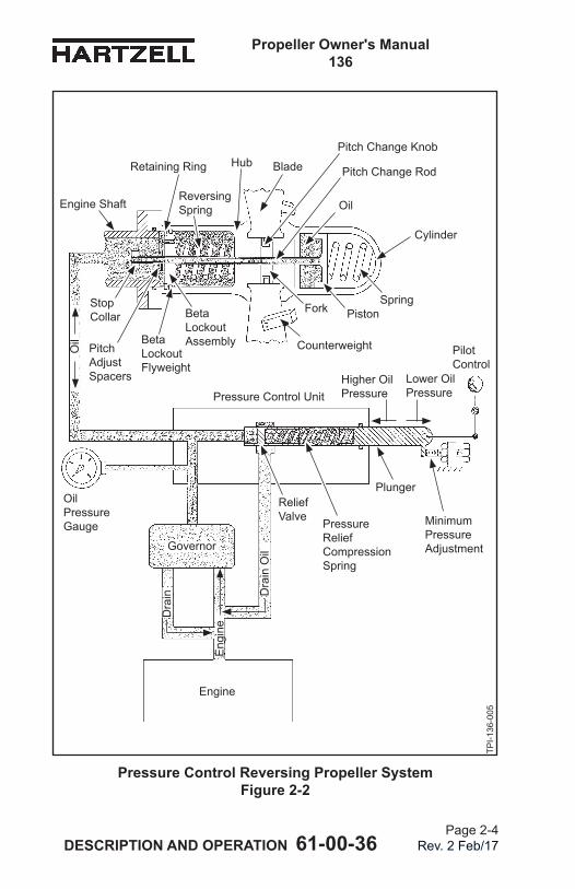
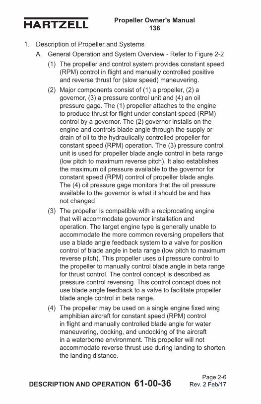
1. Description of Propeller and SystemsA. General Operation and System Overview - Refer to Figure 2-2
(1) The propeller and control system provides constant speed (RPM)controlinflightandmanuallycontrolledpositiveand reverse thrust for (slow speed) maneuvering.
(2) Major components consist of (1) a propeller, (2) a governor, (3) a pressure control unit and (4) an oil pressure gage. The (1) propeller attaches to the engine toproducethrustforflightunderconstantspeed(RPM)control by a governor. The (2) governor installs on the engine and controls blade angle through the supply or drain of oil to the hydraulically controlled propeller for constant speed (RPM) operation. The (3) pressure control unit is used for propeller blade angle control in beta range (low pitch to maximum reverse pitch). It also establishes the maximum oil pressure available to the governor for constant speed (RPM) control of propeller blade angle. The (4) oil pressure gage monitors that the oil pressure available to the governor is what it should be and has not changed
(3) The propeller is compatible with a reciprocating engine that will accommodate governor installation and operation. The target engine type is generally unable to accommodate the more common reversing propellers that use a blade angle feedback system to a valve for position control of blade angle in beta range (low pitch to maximum reverse pitch). This propeller uses oil pressure control to the propeller to manually control blade angle in beta range for thrust control. The control concept is described as pressure control reversing. This control concept does not use blade angle feedback to a valve to facilitate propeller blade angle control in beta range.
(4) Thepropellermaybeusedonasingleenginefixedwingamphibian aircraft for constant speed (RPM) control inflightandmanuallycontrolledbladeangleforwatermaneuvering, docking, and undocking of the aircraft in a waterborne environment. This propeller will not accommodate reverse thrust use during landing to shorten the landing distance.
Propeller Owner's Manual 136
DESCRIPTION AND OPERATION 61-00-36 Page 2-7
Rev. 2 Feb/17
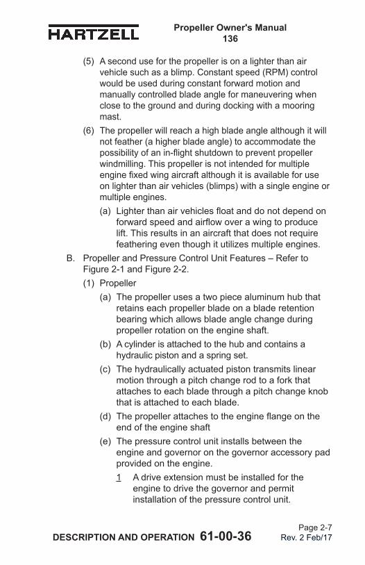
(5) A second use for the propeller is on a lighter than air vehicle such as a blimp. Constant speed (RPM) control would be used during constant forward motion and manually controlled blade angle for maneuvering when close to the ground and during docking with a mooring mast.
(6) The propeller will reach a high blade angle although it will not feather (a higher blade angle) to accommodate the possibilityofanin-flightshutdowntopreventpropellerwindmilling. This propeller is not intended for multiple enginefixedwingaircraftalthoughitisavailableforuseon lighter than air vehicles (blimps) with a single engine or multiple engines. (a) Lighterthanairvehiclesfloatanddonotdependon
forwardspeedandairflowoverawingtoproducelift. This results in an aircraft that does not require featheringeventhoughitutilizesmultipleengines.
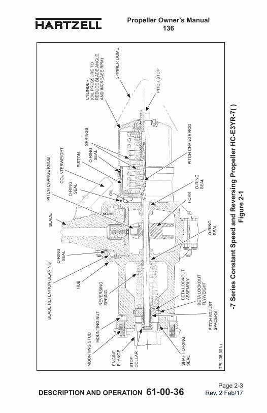
B. Propeller and Pressure Control Unit Features – Refer to Figure 2-1 and Figure 2-2.(1) Propeller
(a) The propeller uses a two piece aluminum hub that retains each propeller blade on a blade retention bearing which allows blade angle change during propeller rotation on the engine shaft.
(b) A cylinder is attached to the hub and contains a hydraulic piston and a spring set.
(c) The hydraulically actuated piston transmits linear motion through a pitch change rod to a fork that attaches to each blade through a pitch change knob that is attached to each blade.
(d) Thepropellerattachestotheengineflangeontheend of the engine shaft
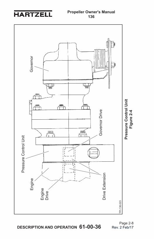
(e) The pressure control unit installs between the engine and governor on the governor accessory pad provided on the engine. 1 A drive extension must be installed for the
engine to drive the governor and permit installation of the pressure control unit.
Propeller Owner's Manual 136
DESCRIPTION AND OPERATION 61-00-36 Page 2-8
Rev. 2 Feb/17
Pres
sure
Con
trol
Uni
t Fi
gure
2-4
TPI-1
36-0
23
Eng
ine
Eng
ine
Driv
e
Pre
ssur
e C
ontro
l Uni
t
Gov
erno
r
Gov
erno
r Driv
eD
rive
Ext
ensi
on
Propeller Owner's Manual 136
DESCRIPTION AND OPERATION 61-00-36 Page 2-9
Rev. 2 Feb/17
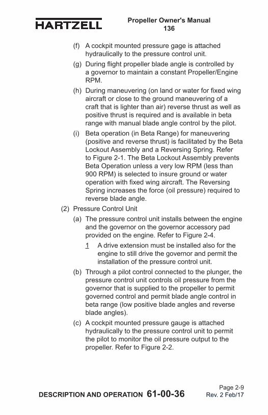
(f) A cockpit mounted pressure gage is attached hydraulically to the pressure control unit.
(g) Duringflightpropellerbladeangleiscontrolledbya governor to maintain a constant Propeller/Engine RPM.
(h) Duringmaneuvering(onlandorwaterforfixedwingaircraft or close to the ground maneuvering of a craft that is lighter than air) reverse thrust as well as positive thrust is required and is available in beta range with manual blade angle control by the pilot.
(i) Beta operation (in Beta Range) for maneuvering (positive and reverse thrust) is facilitated by the Beta Lockout Assembly and a Reversing Spring. Refer to Figure 2-1. The Beta Lockout Assembly prevents Beta Operation unless a very low RPM (less than 900 RPM) is selected to insure ground or water operationwithfixedwingaircraft.TheReversingSpring increases the force (oil pressure) required to reverse blade angle.
(2) Pressure Control Unit(a) The pressure control unit installs between the engine
and the governor on the governor accessory pad provided on the engine. Refer to Figure 2-4.1 A drive extension must be installed also for the
engine to still drive the governor and permit the installation of the pressure control unit.
(b) Through a pilot control connected to the plunger, the pressure control unit controls oil pressure from the governor that is supplied to the propeller to permit governed control and permit blade angle control in beta range (low positive blade angles and reverse blade angles).
(c) A cockpit mounted pressure gauge is attached hydraulically to the pressure control unit to permit the pilot to monitor the oil pressure output to the propeller. Refer to Figure 2-2.
Propeller Owner's Manual 136
DESCRIPTION AND OPERATION 61-00-36 Page 2-10
Rev. 2 Feb/17
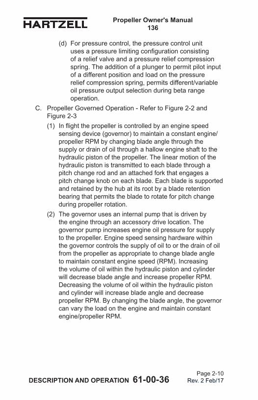
(d) For pressure control, the pressure control unit usesapressurelimitingconfigurationconsistingof a relief valve and a pressure relief compression spring. The addition of a plunger to permit pilot input of a different position and load on the pressure relief compression spring, permits different/variable oil pressure output selection during beta range operation.
C. Propeller Governed Operation - Refer to Figure 2-2 and Figure 2-3(1) Inflightthepropelleriscontrolledbyanenginespeed
sensing device (governor) to maintain a constant engine/propeller RPM by changing blade angle through the supply or drain of oil through a hallow engine shaft to the hydraulic piston of the propeller. The linear motion of the hydraulic piston is transmitted to each blade through a pitch change rod and an attached fork that engages a pitch change knob on each blade. Each blade is supported and retained by the hub at its root by a blade retention bearing that permits the blade to rotate for pitch change during propeller rotation.
(2) The governor uses an internal pump that is driven by the engine through an accessory drive location. The governor pump increases engine oil pressure for supply to the propeller. Engine speed sensing hardware within the governor controls the supply of oil to or the drain of oil from the propeller as appropriate to change blade angle to maintain constant engine speed (RPM). Increasing the volume of oil within the hydraulic piston and cylinder will decrease blade angle and increase propeller RPM. Decreasing the volume of oil within the hydraulic piston and cylinder will increase blade angle and decrease propeller RPM. By changing the blade angle, the governor can vary the load on the engine and maintain constant engine/propeller RPM.
Propeller Owner's Manual 136
DESCRIPTION AND OPERATION 61-00-36 Page 2-11
Rev. 2 Feb/17
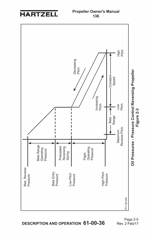
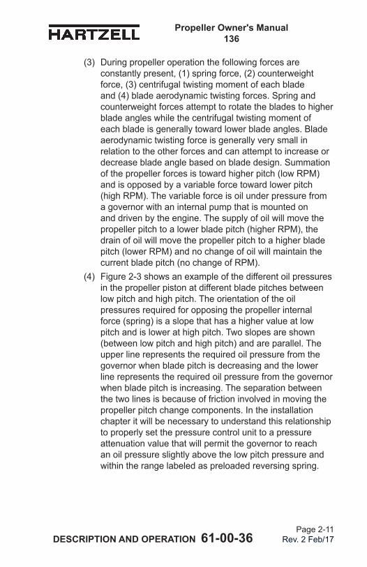
(3) During propeller operation the following forces are constantly present, (1) spring force, (2) counterweight force, (3) centrifugal twisting moment of each blade and (4) blade aerodynamic twisting forces. Spring and counterweight forces attempt to rotate the blades to higher blade angles while the centrifugal twisting moment of each blade is generally toward lower blade angles. Blade aerodynamic twisting force is generally very small in relation to the other forces and can attempt to increase or decrease blade angle based on blade design. Summation of the propeller forces is toward higher pitch (low RPM) and is opposed by a variable force toward lower pitch (high RPM). The variable force is oil under pressure from a governor with an internal pump that is mounted on and driven by the engine. The supply of oil will move the propeller pitch to a lower blade pitch (higher RPM), the drain of oil will move the propeller pitch to a higher blade pitch (lower RPM) and no change of oil will maintain the current blade pitch (no change of RPM).
(4) Figure 2-3 shows an example of the different oil pressures in the propeller piston at different blade pitches between low pitch and high pitch. The orientation of the oil pressures required for opposing the propeller internal force (spring) is a slope that has a higher value at low pitch and is lower at high pitch. Two slopes are shown (between low pitch and high pitch) and are parallel. The upper line represents the required oil pressure from the governor when blade pitch is decreasing and the lower line represents the required oil pressure from the governor when blade pitch is increasing. The separation between the two lines is because of friction involved in moving the propeller pitch change components. In the installation chapter it will be necessary to understand this relationship to properly set the pressure control unit to a pressure attenuation value that will permit the governor to reach an oil pressure slightly above the low pitch pressure and within the range labeled as preloaded reversing spring.
Propeller Owner's Manual 136
DESCRIPTION AND OPERATION 61-00-36 Page 2-12
Rev. 2 Feb/17
D. Propeller Beta (Reverse) Operation - Refer to Figure 2-2 and Figure 2-3(1) Propeller beta operation is in the range between low pitch
and maximum reverse pitch. Blade pitch or blade angle is controlled manually by the pilot through a lever/cable connected to a plunger in the pressure control unit; thus, blade angle control in beta range is not controlled by the RPM sensing hardware of the governor and constant speed operation is not maintained in beta range. RPM will change as blade angle is changed. Blade angle control of the propeller by the governor is disabled and is manually controlled by the pilot.
(2) Constant speed propellers that do not reverse will operate between a high pitch and a low pitch range under governor blade pitch control for constant speed operation. In these propellerslowpitchismaintainedwithafixedstopandwillnot permit blade angle movement below low pitch.
(3) A propeller with reversing capability must be able to reach blade pitch below low pitch in the beta range (between low pitch and maximum reverse pitch). Maximum reverse pitch ismaintainedbyafixedstop.
(4) The low pitch stop on a reversing propeller must function as a stop when in constant speed operation (governor control), but it must permit blade pitch movement below low pitch into the beta range when amphibian water maneuvering or lighter than air vehicle maneuvering is desired. Beta range permits manual selection of a low positive blade pitch for variable low positive thrust and selectable reverse blade pitch for variable reverse thrust.
Thesolutiontotherequirementofafixedlowpitchstopfor constant speed operation and releasable to permit movement into beta range operation is the beta lockout assembly shown in Figure 2-2. This unit is held in place between a preloaded reversing spring and a retaining ring that is anchored in the barrel of the hub, as shown in Figure 2-2.
Propeller Owner's Manual 136
DESCRIPTION AND OPERATION 61-00-36 Page 2-13
Rev. 2 Feb/17
Centrifugal locks built into the beta lockout assembly are RPM sensitive such that they will engage a groove in the hub barrel at RPMs above 900 RPM to prevent axial moment in the barrel of the hub. At an RPM below 900 RPM the centrifugal locks will retract into the body of the low pitch stop unit and permit axial movement in the barrel of the hub for beta range operation.
Forfixedwingamphibianaircraftthisrequiresthattheaircraft is landed with minimum forward movement to permit the engine to be idled down to an RPM below 900 RPM to permit release of the centrifugal locks and allow linear movement of the beta lockout assembly below low pitch into beta range.
A lighter than air vehicle, such as a blimp, will also need to idle the engine below 900 RPM to facilitate movement of blade pitch from low pitch into beta range.
(5) Before selecting beta range for maneuvering (low positive blade pitch and reverse blade pitch) the governor must be set by the pilot to a maximum RPM selection. It is important to understand that all operation in the beta range must be at an RPM less than the maximum governor RPM selection. In this manner the governor interprets all beta range operation as an underspeed and will continue to supply maximum oil pressure to the pressure control unit in an effort to decrease blade angle for RPM increase in a positive thrust constant speed situation.
If the RPM is allowed to exceed the governor maximum RPM selection then the governor will interpret this as an overspeed and will immediately drain oil to force a sudden and unexpected blade angle increase. This will cause a sudden and powerful positive thrust that could cause damage to the aircraft during manual pilot control during maneuvering.
The supply of maximum oil pressure (270 to 300 PSI) to the pressure control unit is required to maintain pilot control of propeller blade angle in beta range (between low pitch and maximum reverse blade angle) for maneuvering. A minimum pressure of 270 PSI from the governor is required to reach maximum reverse pitch. Refer to Figure 2-3.
Propeller Owner's Manual 136
DESCRIPTION AND OPERATION 61-00-36 Page 2-14
Rev. 2 Feb/17
(6) Operation in beta range is at elevated pressures that are considerably above oil pressures required for constant speed operation as shown in Figure 2-3. The slope of the line representing oil pressures required for beta range operation is shown to be much steeper than for constant speed operation.
Operation in constant speed only compresses a spring set located in the propeller cylinder that pushes against the piston. Operation in beta range requires that two spring sets be compressed; one spring set is acting against the piston (as in constant speed operation) and the second spring set is in the barrel of the propeller hub (between the bladesandtheengineflange)andidentifiedasareversingspring in Figure 2-2. The reversing spring is compressed by the moving the beta lockout unit when blade angle movement below low pitch occurs.
Compression of one spring set (for constant speed operation) versus compression of two spring sets (during beta range operation) is why the slope of the operating oil pressure line in constant speed operation is less that the slope of the oil pressure line in beta range.
Propeller Owner's Manual 136
DESCRIPTION AND OPERATION 61-00-36 Page 2-15
Rev. 2 Feb/17
(7) The function of the Pressure Control Unit is to reduce the governor supplied oil pressure of 270 to 300 PSI to a lower oil pressure. Refer to Figure 2-2. One mode of reductionisfixedandthesecondisvariable.Thetwomodes of reduction are discussed in paragraphs 1.D.(7)(a) and 1.D.(7)(b).(a) This adjustment supports governor control constant
speed operation. Initial adjustment of the Pressure Control Unit requires that the plunger position (length of extension from the pressure control unit body) is limited by a restraining bolt or screw. This is to limit the minimum (lower) oil pressure that the Pressure Control Unit will reduce the governor supplied oil pressure of 270 to 300 PSI. This pressure must be high enough to make sure that the governor will be able to supply enough oil pressure to the propeller to reach low pitch during normal constant speed operation (governed control). Refer to Figure 2-3. 1 The minimum pressure adjustment is the lowest
pressure that the pressure control unit will attenuate the governor supplied oil pressure of 270 to 300 PSI. This lowest pressure for the pressure control unit is conversely the maximum pressure permitted by the pressure control unit to reach the propeller during constant speed operation between low pitch and high pitch. Refer to Figure 2-3.
Propeller Owner's Manual 136
DESCRIPTION AND OPERATION 61-00-36 Page 2-16
Rev. 2 Feb/17
(b) During maneuvering, the propeller operates in Beta Range (Low Pitch to Full Reverse Pitch) which is manually selectable. Manual selection of blade angle by the pilot is accomplished by moving the pilot control that pushes a Plunger into the Pressure Control Unit to increase the oil pressure allowed by the Pressure Control Unit to reach the propeller. Refer to Figure 2-2. Control of the higher pressure by the pilot is what allows selection of different blade angles in Beta Range. Refer to Figure 2-3. Oil pressures controlled by the pilot will vary between the minimum oil pressure, that is discussed in paragraph 1.D.(7)(a), through the maximum oil pressure of 270 to 300 PSI available from the governor. Moving toward minimum oil pressure will obtain positive thrust and moving toward maximum oil pressure will obtain negative thrust. Refer to Figure 2-2.
(8) It is recommended that the cockpit mounted lever used by the pilot to control the pressure control unit be equipped with a catch or detent that must be consciously disabled to prevent an unintentional attempt to enter beta range.
(9) Operationinbetarangeduringflightwithafixedwingaircraft is not permitted. A lighter than air vehicle is permitted to operate in beta range with no restrictions sincetheairvehiclefloatsanddoesnotflyonanairfoiland does not stall at a slower forward airspeed.
Propeller Owner's Manual 136
DESCRIPTION AND OPERATION 61-00-36 Page 2-17
Rev. 2 Feb/17
2. Pilot Operation of Propeller Blade Angle in Beta Range (Low Pitch to Full Reverse Pitch) for ManeuveringA. The blade angle selection is manually controlled by the pilot.B. First, decrease throttle to idle to decrease RPM below
900 RPM to disengage the centrifugal locks in the low pitch stop unit.
C. Second, the pilot must select maximum RPM on the governor control.
D. Third, the pilot moves the pilot control cockpit lever past the catch or detent into beta range. The pilot control is connected to the plunger in the pressure control unit to compress the pressure control spring and increase the oil pressure supply to the propeller Refer to Figure 2-2.
E. Fourth, decrease blade angle to approximately neutral thrust, i.e., no forward or reverse sensation in the aircraft.
F. Fifth, increase throttle (for power) to an RPM that is clearly under the maximum RPM selected for governor control. In this manner the pilot will be able to move only the pilot control cockpit lever freely to higher positive pitch (lower oil pressure) still less than low pitch or back through neutral pitch and into reverse pitch (higher oil pressure). This procedure will permit simple one lever control without fear of an overspeed.
WARNING: PROPELLER OVERSPEED WHILE IN BETA RANGE WILL CAUSE SUDDEN AND UNWANTED BLADE ANGLE MOVEMENT THAT IS CONTROLLED BY THE GOVERNOR AND NOT THE PILOT.
(1) Too much power selected when moving through neutral pitch with the pilot control could cause an unwanted overspeed that will prompt the governor to suddenly drop oil pressure (drain oil) and move the propeller to a blade angle higher than low pitch. (a) If this occurs the RPM will probably be higher than
900 RPM and the centrifugal locks will re-engage a groove in the barrel of the hub and prevent reversal even if the pilot control cockpit lever is quickly moved toward a reverse pitch (thrust) selection.
Propeller Owner's Manual 136
DESCRIPTION AND OPERATION 61-00-36 Page 2-18
Rev. 2 Feb/17
(b) This occurrence could be unsettling to the pilot and could cause unwanted and severe movement of the aircraft causing property damage.1 Use of one lever only during beta range
operation is strongly recommended because using two levers (adding the throttle control lever) introduces the strong possibility that the pilot will inadvertently have the throttle at high power while moving the propeller blade angle through neutral pitch (blade angle) and cause overspeed and the unwanted consequences (damage) described in paragraph 2.F.(1).
G. Sixth, pilot selects blade angle as required to obtain the desired thrust direction for maneuvering.
H. Seventh, return the Pilot Control to the original position past the catch or detent out of beta range after maneuvering is complete.
Propeller Owner's Manual 136
DESCRIPTION AND OPERATION 61-00-36 Page 2-19
Rev. 2 Feb/17
(This page is intentionally blank.)
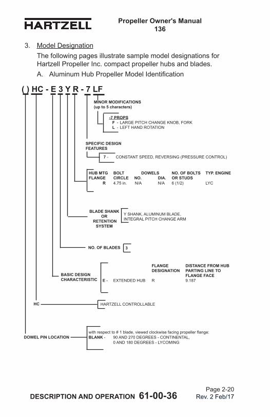
Propeller Owner's Manual 136
DESCRIPTION AND OPERATION 61-00-36 Page 2-20
Rev. 2 Feb/17
3. Model DesignationThe following pages illustrate sample model designations for HartzellPropellerInc.compactpropellerhubsandblades.A. AluminumHubPropellerModelIdentification
( ) HC - E 3 Y R - 7 LF
HARTZELL CONTROLLABLE
DOWEL PIN LOCATION
NO. OF BLADES 3
withrespectto#1blade,viewedclockwisefacingpropellerflange:BLANK - 90 AND 270 DEGREES - CONTINENTAL, 0 AND 180 DEGREES - LYCOMING
BLADE SHANK OR
RETENTION SYSTEM
Y SHANK, ALUMINUM BLADE, INTEGRAL PITCH CHANGE ARM
FLANGE DISTANCE FROM HUB DESIGNATION PARTING LINE TO FLANGE FACEE - EXTENDED HUB R 9.187
HUB MTG BOLT DOWELS NO. OF BOLTS TYP. ENGINE FLANGE CIRCLE NO. DIA. OR STUDS R 4.75 in. N/A N/A 6 (1/2) LYC
BASIC DESIGN CHARACTERISTIC
HC
-7 PROPS F - LARGE PITCH CHANGE KNOB, FORK L - LEFT HAND ROTATION
MINOR MODIFICATIONS (up to 5 characters)
SPECIFIC DESIGN FEATURES
7 - CONSTANT SPEED, REVERSING (PRESSURE CONTROL)
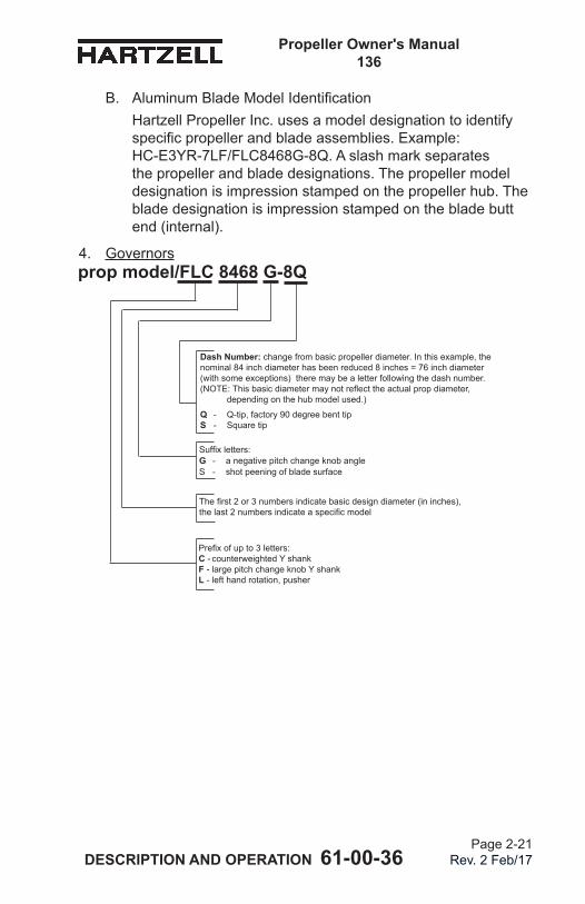
Propeller Owner's Manual 136
DESCRIPTION AND OPERATION 61-00-36 Page 2-21
Rev. 2 Feb/17
Dash Number: change from basic propeller diameter. In this example, the nominal 84 inch diameter has been reduced 8 inches = 76 inch diameter (with some exceptions) there may be a letter following the dash number. (NOTE:Thisbasicdiametermaynotreflecttheactualpropdiameter, depending on the hub model used.)
Q - Q-tip, factory 90 degree bent tip S - Square tip
prop model/FLC 8468 G-8Q
Prefixofupto3letters: C - counterweighted Y shank F - large pitch change knob Y shank L - left hand rotation, pusher
Suffixletters: G - a negative pitch change knob angle S - shot peening of blade surface
Thefirst2or3numbersindicatebasicdesigndiameter(ininches), thelast2numbersindicateaspecificmodel
B. AluminumBladeModelIdentificationHartzellPropellerInc.usesamodeldesignationtoidentifyspecificpropellerandbladeassemblies.Example: HC-E3YR-7LF/FLC8468G-8Q. A slash mark separates the propeller and blade designations. The propeller model designation is impression stamped on the propeller hub. The blade designation is impression stamped on the blade butt end (internal).
4. Governors
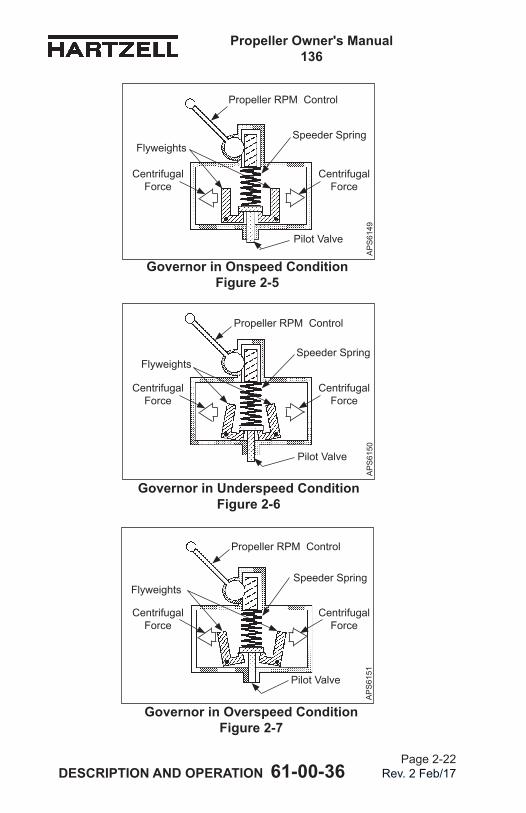
Propeller Owner's Manual 136
DESCRIPTION AND OPERATION 61-00-36 Page 2-22
Rev. 2 Feb/17
Governor in Onspeed Condition Figure 2-5
Governor in Underspeed Condition Figure 2-6
Governor in Overspeed Condition Figure 2-7
Propeller RPM Control
Speeder SpringFlyweights
Pilot Valve
Speeder SpringFlyweights
Pilot Valve
Speeder SpringFlyweights
Pilot Valve
AP
S61
49A
PS
6150
AP
S61
51
Centrifugal Force
Centrifugal Force
Centrifugal Force
Centrifugal Force
Centrifugal Force
Centrifugal Force
Propeller RPM Control
Propeller RPM Control
Propeller Owner's Manual 136
DESCRIPTION AND OPERATION 61-00-36 Page 2-23
Rev. 2 Feb/17
A. Theory of Operation(1) A governor is an engine RPM sensing device and high
pressure oil pump. In a constant speed propeller system, the governor responds to a change in engine RPM by directing oil under pressure to the propeller hydraulic cylinder or by releasing oil from the hydraulic cylinder. The change in oil volume in the hydraulic cylinder changes the blade angle and maintains the propeller system RPM. The governorissetforaspecificRPMviathecockpitpropellercontrol, which compresses or releases the governor speeder spring.
(2) When the engine is operating at the RPM set by the pilot using the cockpit control, the governor is operating onspeed. Refer to Figure 2-5. In an onspeed condition, thecentrifugalforceactingontheflyweightsisbalancedby the speeder spring, and the pilot valve is neither directing oil to nor from the propeller hydraulic cylinder.
(3) When the engine is operating below the RPM set by the pilot using the cockpit control, the governor is operating underspeed. Refer to Figure 2-6. In an underspeed condition,theflyweightstiltinwardbecausethereisnotenoughcentrifugalforceontheflyweightstoovercomethe force of the speeder spring. The pilot valve, forced down by thespeederspring,metersoilflowtodecreasepropellerpitch and raise engine RPM.
(4) When the engine is operating above the RPM set by the pilot using the cockpit control, the governor is operating overspeed. Refer to Figure 2-7. In an overspeed condition,thecentrifugalforceactingontheflyweightsis greaterthanthespeederspringforce.Theflyweightstiltoutward, and raise the pilot valve. The pilot valve then metersoilflowtoincreasepropellerpitchandlowerengine RPM.
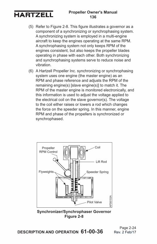
Propeller Owner's Manual 136
DESCRIPTION AND OPERATION 61-00-36 Page 2-24
Rev. 2 Feb/17
Synchronizer/Synchrophaser Governor Figure 2-8
Propeller RPM Control
Speeder SpringFlyweights
Pilot Valve
Coil
Lift Rod
AP
S61
53A
(5) RefertoFigure2-8.Thisfigureillustratesagovernorasacomponentofasynchronizingorsynchrophasingsystem.Asynchronizingsystemisemployedinamulti-engineaircraft to keep the engines operating at the same RPM. A synchrophasing system not only keeps RPM of the engines consistent, but also keeps the propeller blades operatinginphasewitheachother.Bothsynchronizingand synchrophasing systems serve to reduce noise and vibration.
(6) AHartzellPropellerInc.synchronizingorsynchrophasingsystem uses one engine (the master engine) as an RPM and phase reference and adjusts the RPM of the remaining engine(s) [slave engine(s)] to match it. The RPM of the master engine is monitored electronically, and this information is used to adjust the voltage applied to the electrical coil on the slave governor(s). The voltage to the coil either raises or lowers a rod which changes the force on the speeder spring. In this manner, engine RPMandphaseofthepropellersissynchronizedorsynchrophased.
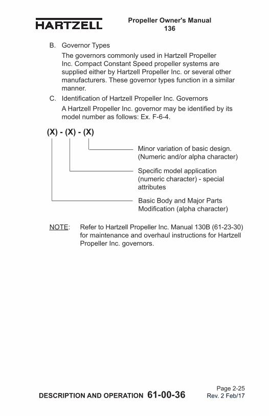
Propeller Owner's Manual 136
DESCRIPTION AND OPERATION 61-00-36 Page 2-25
Rev. 2 Feb/17
B. Governor TypesThegovernorscommonlyusedinHartzellPropellerInc. Compact Constant Speed propeller systems are suppliedeitherbyHartzellPropeller Inc. or several other manufacturers. These governor types function in a similar manner.
C. IdentificationofHartzellPropellerInc.GovernorsAHartzellPropeller Inc. governormaybeidentifiedbyitsmodel number as follows: Ex. F-6-4.
NOTE: RefertoHartzellPropellerInc.Manual130B(61-23-30)formaintenanceandoverhaulinstructionsforHartzellPropeller Inc. governors.
(X) - (X) - (X)
Minor variation of basic design. (Numeric and/or alpha character)
Specificmodelapplication (numeric character) - special attributes
Basic Body and Major Parts Modification(alphacharacter)
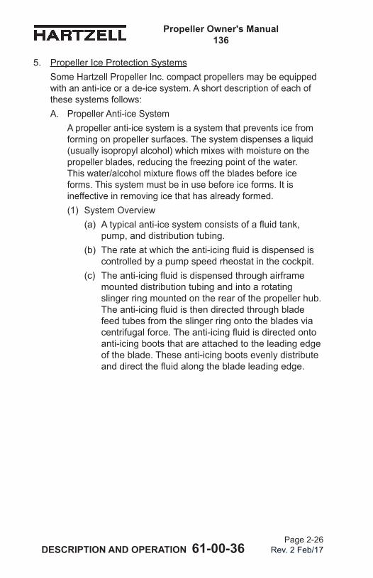
Propeller Owner's Manual 136
DESCRIPTION AND OPERATION 61-00-36 Page 2-26
Rev. 2 Feb/17
5. Propeller Ice Protection SystemsSomeHartzellPropellerInc.compactpropellersmaybeequippedwith an anti-ice or a de-ice system. A short description of each of these systems follows:A. Propeller Anti-ice System
A propeller anti-ice system is a system that prevents ice from forming on propeller surfaces. The system dispenses a liquid (usually isopropyl alcohol) which mixes with moisture on the propellerblades,reducingthefreezingpointofthewater. Thiswater/alcoholmixtureflowsoffthebladesbeforeiceforms. This system must be in use before ice forms. It is ineffective in removing ice that has already formed.(1) System Overview
(a) Atypicalanti-icesystemconsistsofafluidtank,pump, and distribution tubing.
(b) Therateatwhichtheanti-icingfluidisdispensediscontrolled by a pump speed rheostat in the cockpit.
(c) Theanti-icingfluidisdispensedthroughairframemounted distribution tubing and into a rotating slinger ring mounted on the rear of the propeller hub. Theanti-icingfluidisthendirectedthroughbladefeed tubes from the slinger ring onto the blades via centrifugalforce.Theanti-icingfluidisdirectedontoanti-icing boots that are attached to the leading edge of the blade. These anti-icing boots evenly distribute anddirectthefluidalongthebladeleadingedge.
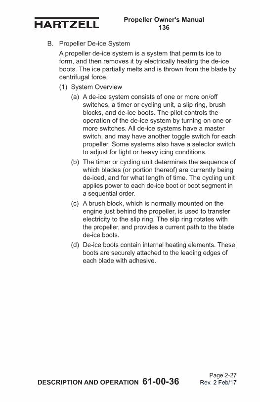
Propeller Owner's Manual 136
DESCRIPTION AND OPERATION 61-00-36 Page 2-27
Rev. 2 Feb/17
B. Propeller De-ice SystemA propeller de-ice system is a system that permits ice to form, and then removes it by electrically heating the de-ice boots. The ice partially melts and is thrown from the blade by centrifugal force.(1) System Overview
(a) A de-ice system consists of one or more on/off switches, a timer or cycling unit, a slip ring, brush blocks, and de-ice boots. The pilot controls the operation of the de-ice system by turning on one or more switches. All de-ice systems have a master switch, and may have another toggle switch for each propeller. Some systems also have a selector switch to adjust for light or heavy icing conditions.
(b) The timer or cycling unit determines the sequence of which blades (or portion thereof) are currently being de-iced, and for what length of time. The cycling unit applies power to each de-ice boot or boot segment in a sequential order.
(c) A brush block, which is normally mounted on the engine just behind the propeller, is used to transfer electricity to the slip ring. The slip ring rotates with the propeller, and provides a current path to the blade de-ice boots.
(d) De-ice boots contain internal heating elements. These boots are securely attached to the leading edges of each blade with adhesive.

Propeller Owner's Manual 136
DESCRIPTION AND OPERATION 61-00-36 Page 2-28
Rev. 2 Feb/17
(This page is intentionally blank.)
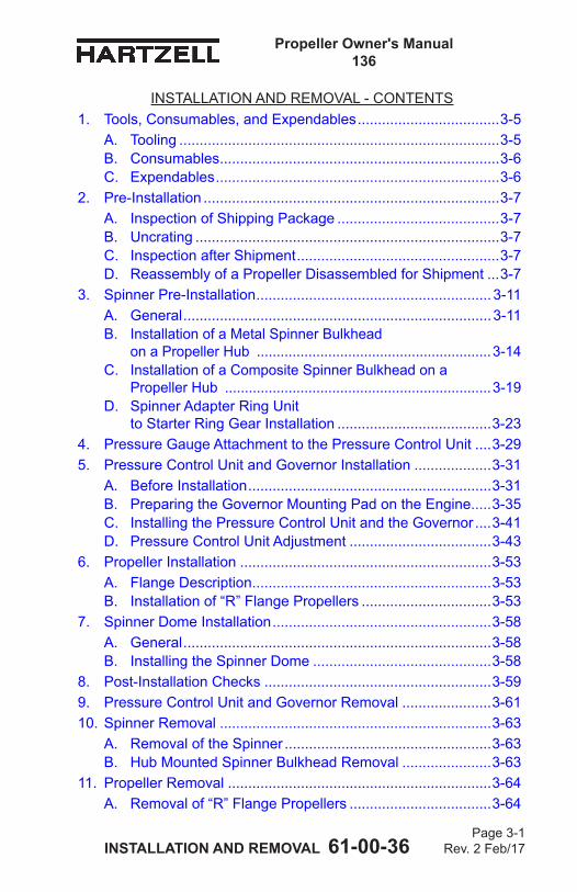
Propeller Owner's Manual 136
INSTALLATION AND REMOVAL 61-00-36 Page 3-1
Rev. 2 Feb/17
INSTALLATION AND REMOVAL - CONTENTS1. Tools, Consumables, and Expendables ...................................3-5
A. Tooling ...............................................................................3-5B. Consumables .....................................................................3-6C. Expendables ......................................................................3-6
2. Pre-Installation .........................................................................3-7A. Inspection of Shipping Package ........................................3-7B. Uncrating ...........................................................................3-7C. Inspection after Shipment ..................................................3-7D. Reassembly of a Propeller Disassembled for Shipment ...3-7
3. Spinner Pre-Installation ..........................................................3-11A. General ............................................................................3-11B. Installation of a Metal Spinner Bulkhead
on a Propeller Hub ...........................................................3-14C. Installation of a Composite Spinner Bulkhead on a
Propeller Hub ...................................................................3-19D. Spinner Adapter Ring Unit
to Starter Ring Gear Installation ......................................3-234. Pressure Gauge Attachment to the Pressure Control Unit ....3-295. Pressure Control Unit and Governor Installation ...................3-31
A. Before Installation ............................................................3-31B. Preparing the Governor Mounting Pad on the Engine. ....3-35C. Installing the Pressure Control Unit and the Governor ....3-41D. Pressure Control Unit Adjustment ...................................3-43
6. Propeller Installation ..............................................................3-53A. Flange Description ...........................................................3-53B. Installation of “R” Flange Propellers ................................3-53
7. Spinner Dome Installation ......................................................3-58A. General ............................................................................3-58B. Installing the Spinner Dome ............................................3-58
8. Post-Installation Checks ........................................................3-599. Pressure Control Unit and Governor Removal ......................3-6110. Spinner Removal ...................................................................3-63
A. Removal of the Spinner ...................................................3-63B. Hub Mounted Spinner Bulkhead Removal ......................3-63
11. Propeller Removal .................................................................3-64A. Removal of “R” Flange Propellers ...................................3-64
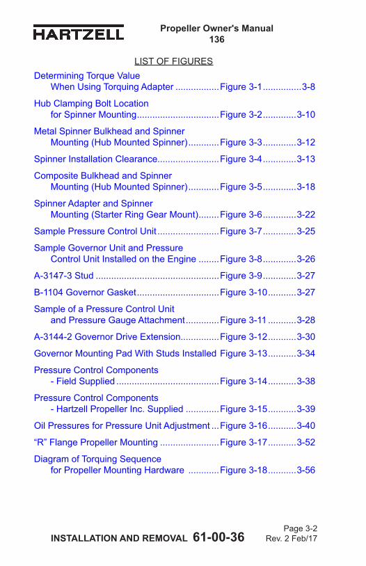
Propeller Owner's Manual 136
INSTALLATION AND REMOVAL 61-00-36 Page 3-2
Rev. 2 Feb/17
LIST OF FIGURESDetermining Torque Value
When Using Torquing Adapter .................Figure 3-1 ...............3-8
Hub Clamping Bolt Location for Spinner Mounting ................................Figure 3-2 .............3-10
Metal Spinner Bulkhead and Spinner Mounting (Hub Mounted Spinner) ............Figure 3-3 .............3-12
Spinner Installation Clearance........................Figure 3-4 .............3-13
Composite Bulkhead and Spinner Mounting (Hub Mounted Spinner) ............Figure 3-5 .............3-18
Spinner Adapter and Spinner Mounting (Starter Ring Gear Mount) ........Figure 3-6 .............3-22
Sample Pressure Control Unit ........................Figure 3-7 .............3-25
Sample Governor Unit and Pressure Control Unit Installed on the Engine ........Figure 3-8 .............3-26
A-3147-3 Stud ................................................Figure 3-9 .............3-27
B-1104 Governor Gasket ................................Figure 3-10 ...........3-27
Sample of a Pressure Control Unit and Pressure Gauge Attachment .............Figure 3-11 ...........3-28
A-3144-2 Governor Drive Extension...............Figure 3-12 ...........3-30
Governor Mounting Pad With Studs Installed Figure 3-13 ...........3-34
Pressure Control Components - Field Supplied ........................................Figure 3-14 ...........3-38
Pressure Control Components - Hartzell Propeller Inc. Supplied .............Figure 3-15 ...........3-39
Oil Pressures for Pressure Unit Adjustment ...Figure 3-16 ...........3-40
“R” Flange Propeller Mounting .......................Figure 3-17 ...........3-52
Diagram of Torquing Sequence for Propeller Mounting Hardware ............Figure 3-18 ...........3-56
Propeller Owner's Manual 136
INSTALLATION AND REMOVAL 61-00-36 Page 3-3
Rev. 2 Feb/17
LIST OF TABLES
Torque Table ...................................................Table 3-1 ................3-9
Metal Spinner Bulkhead Mounting Hardware .Table 3-2 ..............3-16
Composite Spinner Bulkhead Mounting Hardware ..................................Table 3-3 ..............3-20
Propeller/Engine Flange O-rings and Mounting Hardware ...........................Table 3-4 .............3-54

Propeller Owner's Manual 136
INSTALLATION AND REMOVAL 61-00-36 Page 3-4
Rev. 2 Feb/17
(This page is intentionally blank.)
Propeller Owner's Manual 136
INSTALLATION AND REMOVAL 61-00-36 Page 3-5
Rev. 2 Feb/17
1. Tools, Consumables, and ExpendablesNOTE: SpecificHartzellPropellerInc.manualsand
service documents are available on the Hartzell Propeller Inc. website at www.hartzellprop.com. Refer to the Required Publications section in the Introductionchapterofthismanualfortheidentificationof these publications.
The following tools, consumables, and expendables will be required for propeller removal or installation:NOTE: Pressure control reversing compact propellers are
manufacturedwithonebasichubmountingflangedesign.Theflangetypeisdesignatedas“R”. Theflangetypeusedonaparticularpropeller installation is indicated in the propeller model number stamped on the hub. For example, HC-E3YR-7 indicates an“R”flange.RefertoAluminumHubPropellerModelIdentificationintheDescriptionandOperationchapterofthismanualforadescriptionofthisflange.
A. Tooling
CAUTION: USE CARE WHEN USING TOOLS. INCORRECT USE OF TOOLS COULD CAUSE DAMAGE TO THE HUB THAT CANNOT BE REPAIRED AND WOULD REQUIRE THAT THE HUB BE REPLACED.
(1) Tools for Bulkhead Mounting
CAUTION 1: DO NOT USE AN OPEN END WRENCH TO TORQUE THE HUB CLAMPING NUTS. THE POINTED ENDS CAN DAMAGE THE HUB.
CAUTION 2: WHEN USING THE TORQUE WRENCH ADAPTER TE457, MAKE SURE THAT IT IS CORRECTLY ENGAGED ON THE NUT BEFORE APPLYING TORQUE.
(a) Three-bladed propeller hubs:1 Newer hubs have less clearance around the
heads of the hub clamping bolts than the previous design of the compact hub.
Propeller Owner's Manual 136
INSTALLATION AND REMOVAL 61-00-36 Page 3-6
Rev. 2 Feb/17
2 Torque wrench adapter Hartzell Propeller Inc. Part Number 101939 (TE457) is required when torquing the hub clamping bolts for a three-bladed hub.
(2) Tools for Propeller Removal or Installation:R Flange Propellers• Safety wire pliers (Alternate: Safety cable tool) • Torque wrench (1/2 inch drive) • Torque wrench adapters: - Hartzell Propeller Inc. Part Number BST-2860 (TE150) or 3/4 inch crowfoot wrench
NOTE: Using a wrench other than Hartzell Propeller Inc. Part Number BST-2860 (TE150) increases the risk of the wrench causing damage to the hub in the areas around the mounting fasteners
• 3/4 inch open end wrenchB. Consumables
• Quick Dry Stoddard Solvent or Methyl-Ethyl-Ketone (MEK) C. Expendables
• 0.032 inch stainless steel aircraft safety wire (Alternate: 0.032 inch [0.81 mm] aircraft safety cable, and associated hardware) • O-ring - propeller to engine seal (see Table 3-4)
Propeller Owner's Manual 136
INSTALLATION AND REMOVAL 61-00-36 Page 3-7
Rev. 2 Feb/17
2. Pre-InstallationA. Inspection of Shipping Package
(1) Examine the exterior of the shipping container for signs of shipping damage, especially at the box ends around each blade. A hole, tear or crushed appearance at the end of the box (at the propeller tips) may indicate the propeller was dropped during shipment, possibly damaging the blades.
B. Uncrating(1) Placethepropelleronafirmsupport.(2) Remove the banding and any external wood bracing
from the cardboard shipping container. (3) Remove the cardboard from the hub and blades.
CAUTION: DO NOT STAND THE PROPELLER ON A BLADE TIP.
(4) Put the propeller on a padded surface or surfaces to support the propeller.
(5) Remove the plastic dust cover cup from the propeller mountingflange,ifinstalled.
C. Inspection after Shipment(1) After removing the propeller from the shipping container,
examine the propeller components for shipping damage.D. Reassembly of a Propeller Disassembled for Shipment
(1) If a propeller was received disassembled for shipment, it must be reassembled by trained personnel in accordance with Hartzell Propeller Inc. Overhaul and Maintenance Manual 152 (61-10-52).
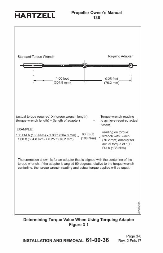
Propeller Owner's Manual 136
INSTALLATION AND REMOVAL 61-00-36 Page 3-8
Rev. 2 Feb/17
(actual torque required) X (torque wrench length) Torque wrench reading (torque wrench length) + (length of adapter) = to achieve required actual torque
Determining Torque Value When Using Torquing Adapter Figure 3-1
AP
S02
12A
0.25 foot(76.2 mm)
1.00 foot(304.8 mm)
Standard Torque Wrench Torquing Adapter
100 Ft-Lb (136 N•m) x 1.00 ft (304.8 mm) 1.00 ft (304.8 mm) + 0.25 ft (76.2 mm)
reading on torque wrench with 3-inch (76.2 mm) adapter for actual torque of 100 Ft-Lb (136 N•m)
EXAMPLE:
= < 80 Ft-Lb(108 N•m)
The correction shown is for an adapter that is aligned with the centerline of the torque wrench. If the adapter is angled 90 degrees relative to the torque wrench centerline, the torque wrench reading and actual torque applied will be equal.
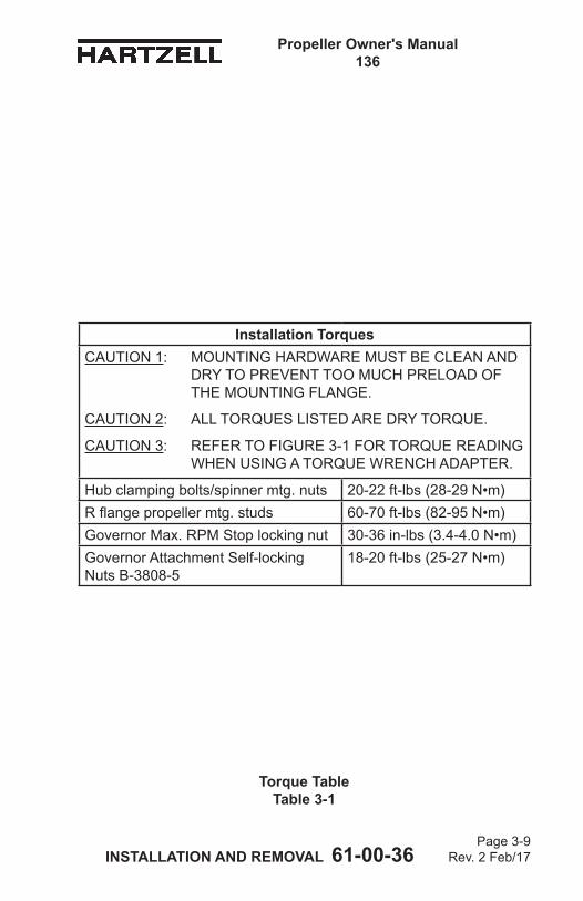
Propeller Owner's Manual 136
INSTALLATION AND REMOVAL 61-00-36 Page 3-9
Rev. 2 Feb/17
Installation TorquesCAUTION 1: MOUNTING HARDWARE MUST BE CLEAN AND
DRY TO PREVENT TOO MUCH PRELOAD OF THE MOUNTING FLANGE.
CAUTION 2: ALL TORQUES LISTED ARE DRY TORQUE.
CAUTION 3: REFER TO FIGURE 3-1 FOR TORQUE READING WHEN USING A TORQUE WRENCH ADAPTER.
Hub clamping bolts/spinner mtg. nuts 20-22 ft-lbs (28-29 N•m)Rflangepropellermtg.studs 60-70 ft-lbs (82-95 N•m)Governor Max. RPM Stop locking nut 30-36 in-lbs (3.4-4.0 N•m)Governor Attachment Self-locking Nuts B-3808-5
18-20 ft-lbs (25-27 N•m)
Torque Table Table 3-1
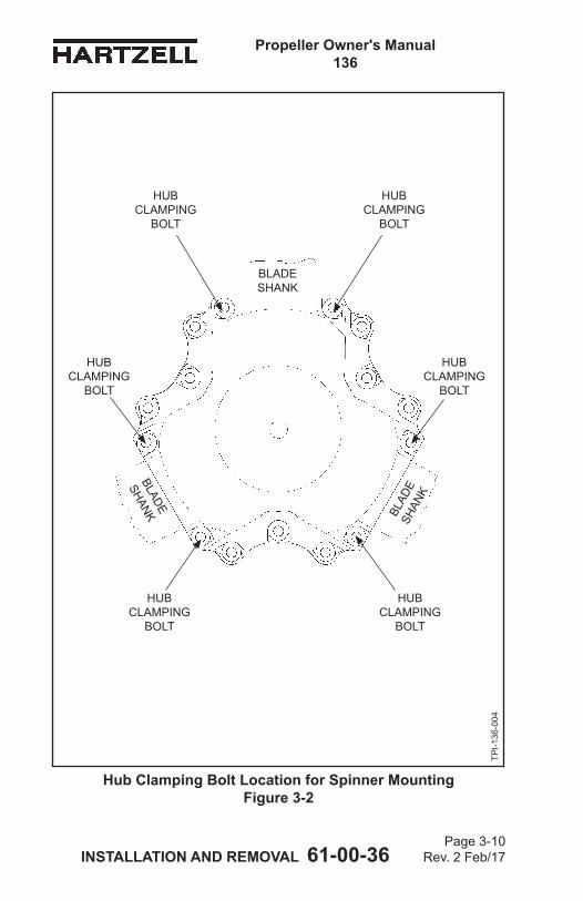
Propeller Owner's Manual 136
INSTALLATION AND REMOVAL 61-00-36 Page 3-10
Rev. 2 Feb/17
Hub Clamping Bolt Location for Spinner Mounting Figure 3-2
TPI-1
36-0
04
BLADE SHANK
BLAD
E SH
ANK
BLADE
SHANK
HUB CLAMPING
BOLT
HUB CLAMPING
BOLT
HUB CLAMPING
BOLT
HUB CLAMPING
BOLT
HUB CLAMPING
BOLT
HUB CLAMPING
BOLT
Propeller Owner's Manual 136
INSTALLATION AND REMOVAL 61-00-36 Page 3-11
Rev. 2 Feb/17
3. Spinner Pre-InstallationA. General
(1) The spinner support must be attached before the propeller can be installed. The spinner dome will attach either to a spinner bulkhead attached to the propeller hub, or, on some Lycoming engine installations, to an adapter ring unit attached to the engine starter ring gear. Follow the applicable directions in this section.
(2) Refer to Figure 3-2. Remove the nuts from the hub clamping bolts that are located on either side of the blade shank. (a) Do not loosen or remove the remaining nuts
and bolts.(3) Refer to Figure 3-2. The spinner may be supplied with
long hub clamping bolts. If the bolts were supplied with the spinner, remove the bolts on either side of the blade shank and replace them with the bolts supplied with the spinner. The supplied hub clamping bolts will be longer than those removed from the hub.NOTE: Depending upon the installation, the propeller
hub may have been shipped from the factory with the longer hub clamping bolts already installed. In this case, the hub clamping bolts will not be supplied with the spinner.
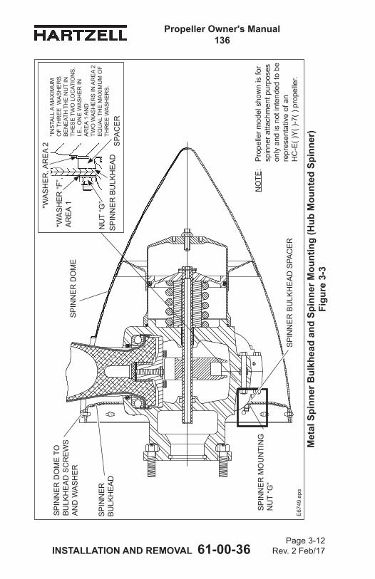
Propeller Owner's Manual 136
INSTALLATION AND REMOVAL 61-00-36 Page 3-12
Rev. 2 Feb/17
Met
al S
pinn
er B
ulkh
ead
and
Spin
ner M
ount
ing
(Hub
Mou
nted
Spi
nner
) Fi
gure
3-3
NO
TE:
Pro
pelle
r mod
el s
how
n is
for
spin
ner a
ttach
men
t pur
pose
s on
ly a
nd is
not
inte
nded
to b
e re
pres
enta
tive
of a
n
HC
-E( )
Y( )
-7( )
pro
pelle
r.
SP
INN
ER
B
ULK
HE
AD
SP
INN
ER
BU
LKH
EA
D S
PAC
ER
SP
INN
ER
MO
UN
TIN
G
NU
T “G
”
SP
INN
ER
DO
ME
TO
B
ULK
HE
AD
SC
RE
WS
A
ND
WA
SH
ER
E67
49.e
ps
NU
T “G
”*WA
SH
ER
, AR
EA
2*I
NS
TALL
A M
AX
IMU
M
OF
THR
EE
WA
SH
ER
S
BE
NE
ATH
TH
E N
UT
IN
THE
SE
TW
O L
OC
ATIO
NS
, I.E
., O
NE
WA
SH
ER
IN
AR
EA
1 A
ND
TW
O W
ASH
ERS
IN A
RE
A 2
E
QU
AL
THE
MA
XIM
UM
OF
THR
EE
WA
SH
ER
S.
*WA
SH
ER
“F”,
AR
EA
1
SPA
CE
RS
PIN
NE
R B
ULK
HE
AD
SP
INN
ER
DO
ME
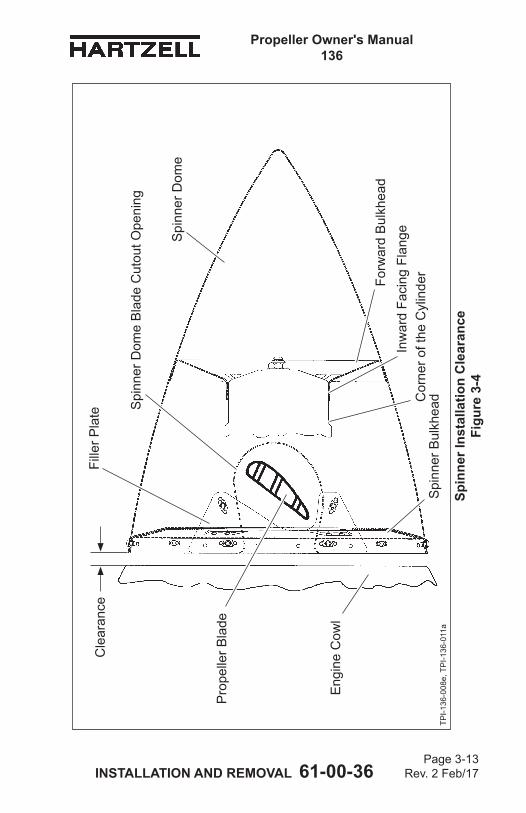
Propeller Owner's Manual 136
INSTALLATION AND REMOVAL 61-00-36 Page 3-13
Rev. 2 Feb/17
Spin
ner I
nsta
llatio
n C
lear
ance
Fi
gure
3-4
Spi
nner
Bul
khea
d
Eng
ine
Cow
l
TPI-1
36-0
08e,
TP
I-136
-011
a
Spi
nner
Dom
e
Spi
nner
Dom
e B
lade
Cut
out O
peni
ng
Forw
ard
Bul
khea
d
Fille
r Pla
teC
lear
ance
Cor
ner o
f the
Cyl
inde
rIn
war
d Fa
cing
Fla
nge
Pro
pelle
r Bla
de
Propeller Owner's Manual 136
INSTALLATION AND REMOVAL 61-00-36 Page 3-14
Rev. 2 Feb/17
B. Installation of a Metal Spinner Bulkhead on a Propeller Hub
CAUTION: INSTRUCTIONS AND PROCEDURES IN THIS SECTION MAY INVOLVE PROPELLER CRITICAL PARTS. REFER TO THE INTRODUCTION CHAPTER OF THIS MANUAL FOR INFORMATION ABOUT PROPELLER CRITICAL PARTS. REFER TO THE ILLUSTRATED PARTS LIST CHAPTER OF THE APPLICABLE OVERHAUL MANUAL FOR THE IDENTIFICATION OF SPECIFIC PROPELLER CRITICAL PARTS.
(1) Spinner installation must make sure of clearance in the following areas:(a) The spinner bulkhead must be spaced between the
hub and the engine cowl to permit the spinner dome blade cut-out openings to clear the propeller blades at all blade angle locations. Refer to Figure 3-4. 1 Thespinnerbulkheadandanyattachedfiller
plate must also clear the propeller blades at all blade angle locations. Refer to Figure 3-4.
(b) The edge of the spinner bulkhead and the installed spinner dome that faces the engine cowl must have space to clear the engine cowl and avoid interference during propeller/engine operation. Refer to Figure 3-4.
(c) The hub clamping bolts on which the spinner bulkhead is attached must not be so long that the bolts interfere with the engine cowl during propeller/engine operation. Refer to Figure 3-4.1 On some installations, it may be necessary to
install spacer(s)/washer(s) between the head of each hub clamping bolt and the hub to move the threaded end of the bolt away from the engine cowl. Refer to Figure 3-4.
Propeller Owner's Manual 136
INSTALLATION AND REMOVAL 61-00-36 Page 3-15
Rev. 2 Feb/17
(d) The spinner dome, spinner bulkhead, and the hub clamping bolts must not interfere with, or bind with, anti-ice or de-ice hardware, if installed.
(e) If a spinner forward bulkhead is installed and is bonded to the spinner dome, make sure that the inwardfacingflangethatpilotsonthepropellercylinder does not interfere with a corner on the propeller cylinder. Refer to Figure 3-4.
(2) Additional washers/spacers may have been installed on the hub clamping bolts from the factory to help with the installation of a reusable self-locking nut on the threaded part of each hub clamping bolt. (a) The additional washer(s)/spacer(s) must be removed
before spinner installation.(3) Install a washer or washers in Area 2 on the hub
clamping bolts if required, to make sure of clearance as listed in paragraphs 3.B(1)(a) through 3.B(1)(e). Refer to Figure 3-3.
(4) Install a spacer or spacers, if required, on each hub clamping bolt between the bulkhead and hub or bulkhead and washer(s).
CAUTION: DO NOT PERMIT THE SPINNER BULKHEAD TO TOUCH THE HUB.
(5) Install the spinner bulkhead over the hub clamping bolt locations as shown in Figure 3-2. The spinner bulkhead will be supported by some combination of spacer(s) or washer(s). (a) The spinner bulkhead must touch spacers(s) or
washer(s), not the hub. NOTE: If the spinner bulkhead and the hub touch,
it could cause damage to the spinner bulkhead and the hub.
(6) Installatleastoneflatwasher“F”inArea1onthehubcamping bolts over the spinner bulkhead. Refer to Figure 3-3 and Table 3-2.
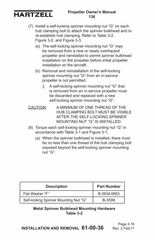
Propeller Owner's Manual 136
INSTALLATION AND REMOVAL 61-00-36 Page 3-16
Rev. 2 Feb/17
(7) Install a self-locking spinner mounting nut “G” on each hub clamping bolt to attach the spinner bulkhead and to re-establish hub clamping. Refer to Table 3-2, Figure 3-2, and Figure 3-3.(a) The self-locking spinner mounting nut “G” may
be removed from a new or newly overhauled propeller and reinstalled to permit spinner bulkhead installation on the propeller before initial propeller installation on the aircraft.
(b) Removal and reinstallation of the self-locking spinner mounting nut “G” from an in-service propeller is not permitted.1 A self-locking spinner mounting nut “G” that
is removed from an in-service propeller must be discarded and replaced with a new self-locking spinner mounting nut “G”.
CAUTION: A MINIMUM OF ONE THREAD OF THE HUB CLAMPING BOLT MUST BE VISIBLE AFTER THE SELF-LOCKING SPINNER MOUNTING NUT “G” IS INSTALLED.
(8) Torque each self-locking spinner mounting nut “G” in accordance with Table 3-1 and Figure 3-1. (a) When the spinner bulkhead is installed, there must
be no less than one thread of the hub clamping bolt exposed beyond the self-locking spinner mounting nut “G”.
Description Part Number
Flat Washer “F” B-3834-0663Self-locking Spinner Mounting Nut “G” B-3599
Metal Spinner Bulkhead Mounting Hardware Table 3-2

Propeller Owner's Manual 136
INSTALLATION AND REMOVAL 61-00-36 Page 3-17
Rev. 2 Feb/17
(This page is intentionally blank.)
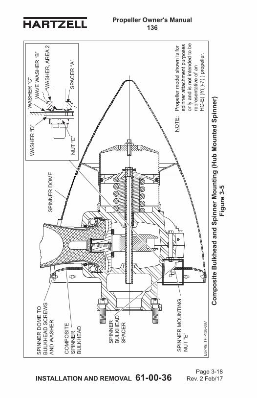
Propeller Owner's Manual 136
INSTALLATION AND REMOVAL 61-00-36 Page 3-18
Rev. 2 Feb/17
Com
posi
te B
ulkh
ead
and
Spin
ner M
ount
ing
(Hub
Mou
nted
Spi
nner
) Fi
gure
3-5
CO
MP
OS
ITE
S
PIN
NE
R
BU
LKH
EA
D
SP
INN
ER
B
ULK
HE
AD
S
PAC
ER
SP
INN
ER
MO
UN
TIN
G
NU
T ”E
”
SP
INN
ER
DO
ME
TO
B
ULK
HE
AD
SC
RE
WS
A
ND
WA
SH
ER
E67
49, T
PI-1
36-0
07
NO
TE:
Pro
pelle
r mod
el s
how
n is
for
spin
ner a
ttach
men
t pur
pose
s on
ly a
nd is
not
inte
nded
to b
e re
pres
enta
tive
of a
n
HC
-E( )
Y( )
-7( )
pro
pelle
r.
NU
T “E
”S
PAC
ER
“A”
WA
SH
ER
“D”
WAV
E W
AS
HE
R “B
” W
AS
HE
R “C
”
SP
INN
ER
DO
ME
*WA
SH
ER
, AR
EA
2
Propeller Owner's Manual 136
INSTALLATION AND REMOVAL 61-00-36 Page 3-19
Rev. 2 Feb/17
C. Installation of a Composite Spinner Bulkhead on a Propeller Hub
CAUTION: INSTRUCTIONS AND PROCEDURES IN THIS SECTION MAY INVOLVE PROPELLER CRITICAL PARTS. REFER TO THE INTRODUCTION CHAPTER OF THIS MANUAL FOR INFORMATION ABOUT PROPELLER CRITICAL PARTS. REFER TO THE ILLUSTRATED PARTS LIST CHAPTER OF THE APPLICABLE OVERHAUL MANUAL(S) FOR THE IDENTIFICATION OF SPECIFIC PROPELLER CRITICAL PARTS.
(1) Spinner installation must make sure of clearance in the following areas:(a) The spinner bulkhead must be spaced between the
hub and the engine cowl to permit the spinner dome blade cut-out openings to clear the propeller blades at all blade angle locations. Refer to Figure 3-4. 1 Thespinnerbulkheadandanyattachedfiller
plate must also clear the propeller blades at all blade angle locations. Refer to Figure 3-4.
(b) The edge of the spinner bulkhead and the installed spinner dome that faces the engine cowl must have space to clear the engine cowl and avoid interference during propeller/engine operation. Refer to Figure 3-4.
(c) The hub clamping bolts on which the spinner bulkhead is attached must not be so long that the bolts interfere with the engine cowl during propeller/engine operation. Refer to Figure 3-4.1 On some installations, it may be necessary to
install spacer(s)/washer(s) between the head of each hub clamping bolt to move the threaded end of the bolt away from the engine cowl. Refer to Figure 3-4.
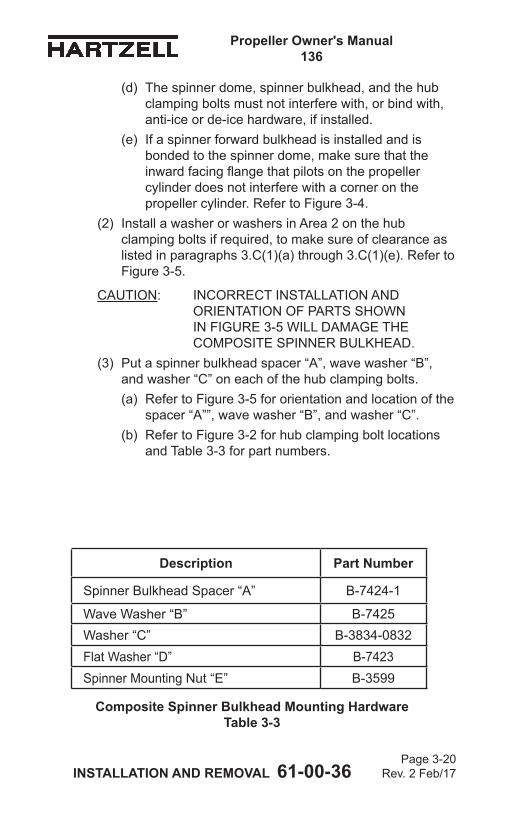
Propeller Owner's Manual 136
INSTALLATION AND REMOVAL 61-00-36 Page 3-20
Rev. 2 Feb/17
Description Part Number
Spinner Bulkhead Spacer “A” B-7424-1
Wave Washer “B” B-7425Washer “C” B-3834-0832Flat Washer “D” B-7423Spinner Mounting Nut “E” B-3599
Composite Spinner Bulkhead Mounting Hardware Table 3-3
(d) The spinner dome, spinner bulkhead, and the hub clamping bolts must not interfere with, or bind with, anti-ice or de-ice hardware, if installed.
(e) If a spinner forward bulkhead is installed and is bonded to the spinner dome, make sure that the inwardfacingflangethatpilotsonthepropellercylinder does not interfere with a corner on the propeller cylinder. Refer to Figure 3-4.
(2) Install a washer or washers in Area 2 on the hub clamping bolts if required, to make sure of clearance as listed in paragraphs 3.C(1)(a) through 3.C(1)(e). Refer to Figure 3-5.
CAUTION: INCORRECT INSTALLATION AND ORIENTATION OF PARTS SHOWN IN FIGURE 3-5 WILL DAMAGE THE COMPOSITE SPINNER BULKHEAD.
(3) Put a spinner bulkhead spacer “A”, wave washer “B”, and washer “C” on each of the hub clamping bolts. (a) Refer to Figure 3-5 for orientation and location of the
spacer “A””, wave washer “B”, and washer “C”.(b) Refer to Figure 3-2 for hub clamping bolt locations
and Table 3-3 for part numbers.
Propeller Owner's Manual 136
INSTALLATION AND REMOVAL 61-00-36 Page 3-21
Rev. 2 Feb/17
(4) Install the composite spinner bulkhead over the installed spacers “A”, wave washers “B”, and washers “C” on the hub clamping bolts. (a) Refer to Table 3-3 for part numbers.(b) Refer to Figure 3-5 for orientation and location.
(5) Installaflatwasher“D”onthehubclampingbolts,over the composite spinner bulkhead. Refer to Figure 3-5 and Table 3-3.
(6) Install a self-locking spinner mounting nut “E” on each of the hub clamping bolts used to mount the spinner bulkhead. (a) The self-locking nut may be removed from a new or
newly overhauled propeller and reinstalled to permit spinner bulkhead installation on the propeller before initial propeller installation on the aircraft.
(b) Removal and reinstallation of the self-locking nut from an in-service propeller is not permitted.1 A self-locking nut that is removed from an
in-service propeller must be discarded and replaced with a new self-locking nut.
CAUTION: A MINIMUM OF ONE THREAD OF THE HUB CLAMPING BOLT MUST BE VISIBLE AFTER THE SPINNER MOUNTING NUT IS INSTALLED.
(7) Torque each self-locking nut “E” in accordance with Table 3-1 and Figure 3-1.(a) When the spinner bulkhead is installed, there must
be no less than one thread of the hub clamping bolt exposed beyond the spinner mounting nut “E”.
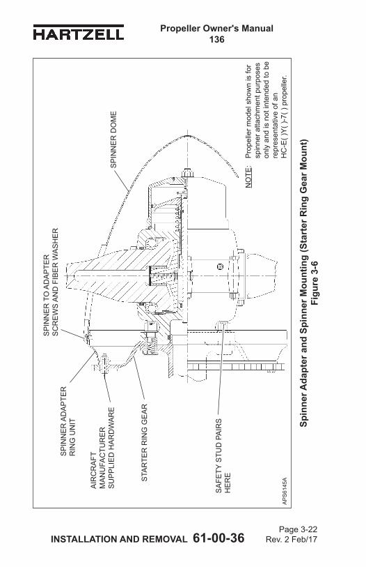
Propeller Owner's Manual 136
INSTALLATION AND REMOVAL 61-00-36 Page 3-22
Rev. 2 Feb/17
Spin
ner A
dapt
er a
nd S
pinn
er M
ount
ing
(Sta
rter
Rin
g G
ear M
ount
) Fi
gure
3-6
SP
INN
ER
AD
AP
TER
R
ING
UN
IT
STA
RTE
R R
ING
GE
AR
AIR
CR
AFT
M
AN
UFA
CTU
RE
R
SU
PP
LIE
D H
AR
DW
AR
E
SP
INN
ER
TO
AD
AP
TER
S
CR
EW
S A
ND
FIB
ER
WA
SH
ER
SA
FETY
STU
D P
AIR
S
HE
RE
AP
S61
45A
NO
TE:
Pro
pelle
r mod
el s
how
n is
for
spin
ner a
ttach
men
t pur
pose
s on
ly a
nd is
not
inte
nded
to b
e re
pres
enta
tive
of a
n
HC
-E( )
Y( )
-7( )
pro
pelle
r.
SP
INN
ER
DO
ME
Propeller Owner's Manual 136
INSTALLATION AND REMOVAL 61-00-36 Page 3-23
Rev. 2 Feb/17
D. Spinner Adapter Ring Unit to Starter Ring Gear Installation
CAUTION: INSTALL SPINNER ADAPTER BOLTS SO THAT THE BOLT HEADS ARE AT THE REAR OF THE STARTER RING GEAR AS INDICATED IN FIGURE 3-6. BOLTS INSTALLED INCORRECTLY MAY DAMAGE ENGINE COMPONENTS.
(1) Install the spinner adapter ring unit (supplied by Hartzell Propeller Inc.) to the starter ring gear (supplied by the engine manufacturer) using the hardware supplied by the airframe manufacturer. Refer to Figure 3-6.
(2) Torquetheboltsasspecifiedbytheairframemanufacturer.
Propeller Owner's Manual 136
INSTALLATION AND REMOVAL 61-00-36 Page 3-24
Rev. 2 Feb/17
(This page is intentionally blank.)
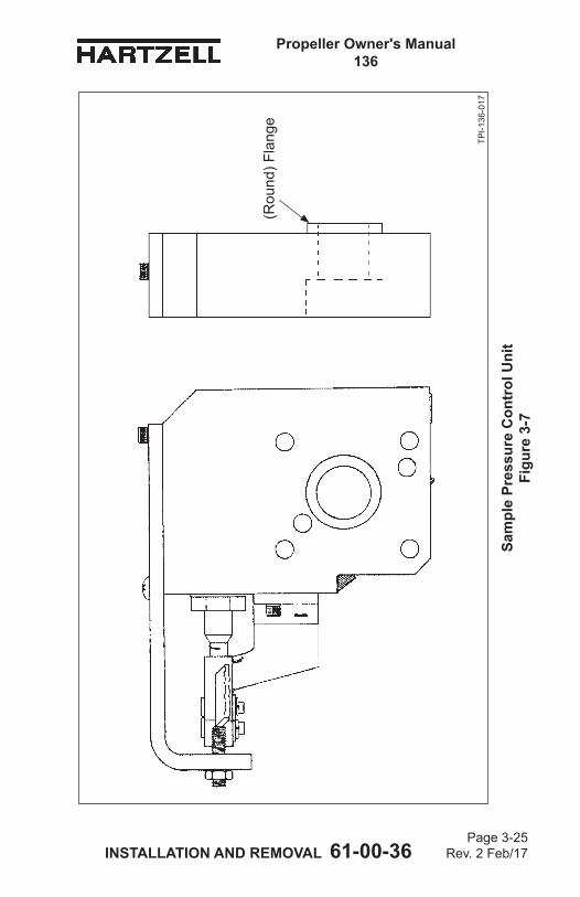
Propeller Owner's Manual 136
INSTALLATION AND REMOVAL 61-00-36 Page 3-25
Rev. 2 Feb/17
TPI-1
36-0
17
Sam
ple
Pres
sure
Con
trol
Uni
t Fi
gure
3-7
(Rou
nd) F
lang
e
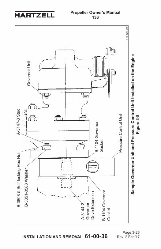
Propeller Owner's Manual 136
INSTALLATION AND REMOVAL 61-00-36 Page 3-26
Rev. 2 Feb/17
TPI-1
36-0
16
Sam
ple
Gov
erno
r Uni
t and
Pre
ssur
e C
ontr
ol U
nit I
nsta
lled
on th
e En
gine
Fi
gure
3-8
A-3
147-
3 S
tud
B-3
808-
5 S
elf-l
ocki
ng H
ex N
ut
B-3
851-
0563
Was
her
Gov
erno
r Uni
t
B-1
104
Gov
erno
r G
aske
t
Pre
ssur
e C
ontro
l Uni
t
A-3
144-
2
Gov
erno
r D
rive
Ext
ensi
onB
-110
4 G
over
nor
Gas
ket
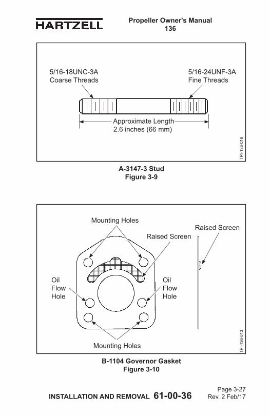
Propeller Owner's Manual 136
INSTALLATION AND REMOVAL 61-00-36 Page 3-27
Rev. 2 Feb/17
A-3147-3 Stud Figure 3-9
TPI-1
36-0
18
B-1104 Governor Gasket Figure 3-10
TPI-1
36-0
13
5/16-18UNC-3ACoarse Threads
5/16-24UNF-3AFine Threads
Raised Screen
Mounting Holes
Mounting Holes
Raised Screen
Oil Flow Hole
Oil Flow Hole
Approximate Length 2.6 inches (66 mm)
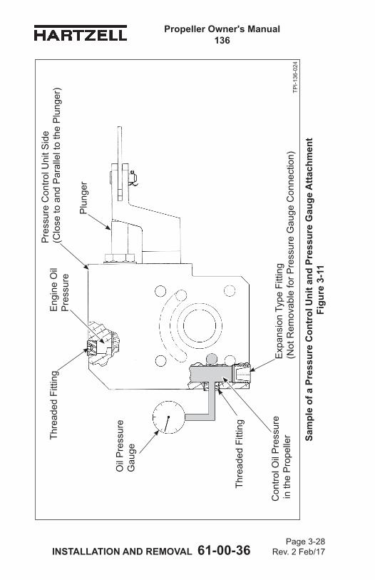
Propeller Owner's Manual 136
INSTALLATION AND REMOVAL 61-00-36 Page 3-28
Rev. 2 Feb/17
TPI-1
36-0
24
Sam
ple
of a
Pre
ssur
e C
ontr
ol U
nit a
nd P
ress
ure
Gau
ge A
ttach
men
t Fi
gure
3-1
1
Pre
ssur
e C
ontro
l Uni
t Sid
e
(Clo
se to
and
Par
alle
l to
the
Plu
nger
)
Con
trol O
il P
ress
ure
in th
e P
rope
ller
Thre
aded
Fitt
ing
Oil
Pre
ssur
e G
auge
Thre
aded
Fitt
ing
Exp
ansi
on T
ype
Fitti
ng
(Not
Rem
ovab
le fo
r Pre
ssur
e G
auge
Con
nect
ion)
Eng
ine
Oil
Pre
ssur
e
Plu
nger
Propeller Owner's Manual 136
INSTALLATION AND REMOVAL 61-00-36 Page 3-29
Rev. 2 Feb/17
4. Pressure Gauge Attachment to the Pressure Control UnitA. Hydraulic connection of the cockpit mounted pressure gauge
is shown in Figure 3-11.B. The pressure gauge is locally procured.
(1) The pressure range of the pressure gauge must be from a minimum of no more than 25 psi through a high pressure of no less than 300 psi.
(2) Aliquidfilledpressuregaugeisrecommendedfordamping of the needle movement.
C. There are many pressure control unit designs available because of the unique requirements of each installation/application. (1) Figure 3-11 shows a sample pressure control unit, which
can vary from the pressure control unit that is suppled.D. The pressure control unit side that is close to and parallel to
theplungerwillhaveseveralthreadedfittingstoconnecttoengine oil pressure and internal porting. Refer to Figure 3-11.(1) The oil pressure gauge is NOT to be connected to the
pressurecontrolunitatthesethreadedfittings.(2) Theoilpressuresunderthesefittingsarenot
representative of the control oil pressure in the propeller. Refer to Figure 3-11.
E. The oil pressure gauge is shown attached to the pressure controlunitatathreadedfittingthataccessesthecontroloilpressure in the propeller. Refer to Figure 3-11.(1) Thethreadedfittingiseasilyremovableandreplaceable
withanotherfittingandhydraulictubeforconnectiontothe pressure gauge.
F. Somepressurecontrolunitshaveoneoftwofittings,thataccess the control oil pressure in the propeller, as an expansiontypefittingthatinstallsinasmoothboreandisnotfieldremovableforpressuregaugeconnection.RefertoFigure 3-11.
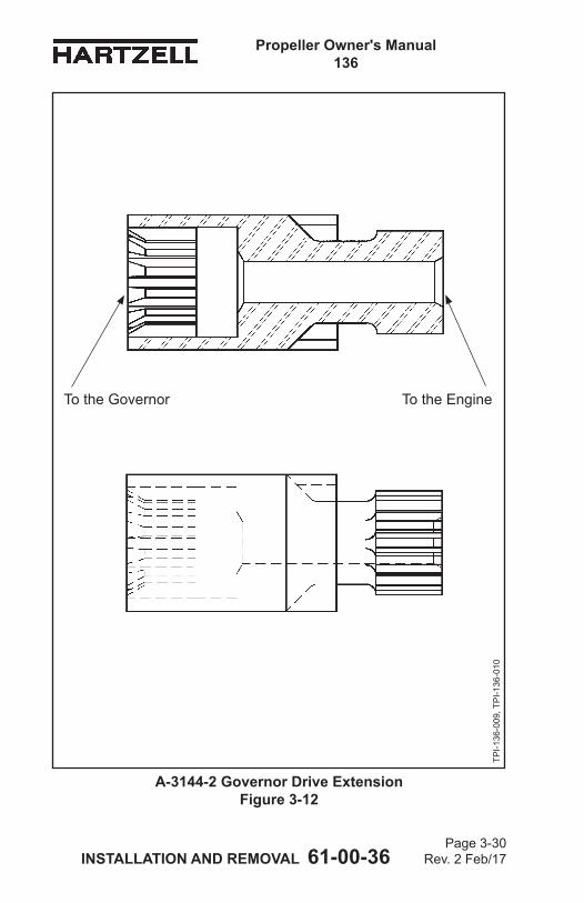
Propeller Owner's Manual 136
INSTALLATION AND REMOVAL 61-00-36 Page 3-30
Rev. 2 Feb/17
A-3144-2 Governor Drive Extension Figure 3-12
TPI-1
36-0
09, T
PI-1
36-0
10
To the Governor To the Engine
Propeller Owner's Manual 136
INSTALLATION AND REMOVAL 61-00-36 Page 3-31
Rev. 2 Feb/17
5. Pressure Control Unit and Governor InstallationNOTE: SpecificHartzellPropellerInc.manualsand
service documents are available on the Hartzell Propeller Inc. website at www.hartzellprop.com. Refer to the Required Publications section in the Introductionchapterofthismanualfortheidentificationof these publications
A. Before Installation(1) Before installation the following items must be available:
(a) One pressure control unit, available from Hartzell Propeller Inc. 1 For a sample pressure control unit, refer to
Figure 3-7. 2 Thespecificpressurecontrolunitsuppliedmay
vary from the sample shown in Figure 3-7.(a) The part number for the pressure control
unit is as required for the applicable installation.
(b) One governor unit, available from Hartzell Propeller Inc. 1 For a sample governor that is shown in the
installed position, refer to Figure 3-8.(a) The part number for the governor is as
required for the applicable installation.(c) Four A-3147-3 studs, available from Hartzell
Propeller Inc. Refer to Figure 3-9.(d) Two B-1104 governor gaskets, available from
Hartzell Propeller Inc. Refer to Figure 3-10.(e) One A-3144-2 governor drive extension, available
from Hartzell Propeller Inc. Refer to Figure 3-12.(f) Four B-3808-5 self-locking hex nuts. Refer to
Figure 3-8.(g) Four B-3851-0563 washers. Refer to Figure 3-8.(h) Threadlocker CM152, available from Hartzell
Propeller Inc. or locally procured
Propeller Owner's Manual 136
INSTALLATION AND REMOVAL 61-00-36 Page 3-32
Rev. 2 Feb/17
(i) Primer T CM127, available from Hartzell Propeller Inc. or locally procured
(j) A torque wrench and a torque wrench adapter to attach to B-3808-5 self-locking hex nuts (1/2 inch acrosstheflats), locally procured
(k) Stud installer/removertofita5/16-UNF24-3Athread,locally procured
Propeller Owner's Manual 136
INSTALLATION AND REMOVAL 61-00-36 Page 3-33
Rev. 2 Feb/17
(This page is intentionally blank.)
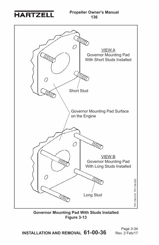
Propeller Owner's Manual 136
INSTALLATION AND REMOVAL 61-00-36 Page 3-34
Rev. 2 Feb/17
Governor Mounting Pad With Studs Installed Figure 3-13
TPI-1
36-0
19, T
PI-1
36-0
20
VIEW AGovernor Mounting Pad
With Short Studs Installed
VIEW BGovernor Mounting Pad
With Long Studs Installed
Short Stud
Long Stud
Governor Mounting Pad Surface on the Engine
Propeller Owner's Manual 136
INSTALLATION AND REMOVAL 61-00-36 Page 3-35
Rev. 2 Feb/17
B. Preparing the Governor Mounting Pad on the Engine.(1) General
(a) If a governor only was previously installed on the engine, the four studs installed in the governor mounting pad will be too short for the required installation of the pressure control unit between the governor and the engine.1 Figure 3-13, View A, shows the governor
mounting pad on the engine with short studs installed.
2 Figure 3-13, View B, shows the governor mounting pad on the engine with long studs installed.
(b) The four long studs are Hartzell Propeller Inc. part number A-3147-3. 1 The A-3147-3 studs have a 5/16-24UNF-3A
thread(finethread)ononeendanda5/16-18UNC-3A thread (coarse thread) on the other end and are approximately 2.6 inches (66 mm) long.
(2) Using a locally procured stud installer/remover, remove the four short studs.
(3) Using a plastic tool, remove any remaining gasket material to make the governor mounting pad surface on theengineflat.
Propeller Owner's Manual 136
INSTALLATION AND REMOVAL 61-00-36 Page 3-36
Rev. 2 Feb/17
WARNING: ADHESIVES AND SOLVENTS ARE FLAMMABLE AND TOXIC TO THE SKIN, EYES, AND RESPIRATORY TRACT. SKIN AND EYE PROTECTION ARE REQUIRED. AVOID PROLONGED CONTACT AND BREATHING OF VAPORS. USE SOLVENT RESISTANT GLOVES TO MINIMIZE SKIN CONTACT AND WEAR SAFETY GLASSES FOR EYE PROTECTION. USE IN A WELL VENTILATED AREA AWAY FROM SPARKS AND FLAME. READ AND OBSERVE ALL WARNING LABELS.
(4) Using solvent MEK CM106 or MPK CM219, clean the governor mounting pad surface on the engine.
(5) Using solvent MEK CM106 or MPK CM219, clean each of the four 5/16-18 threaded holes in the governor mounting pad on the engine.
(6) Using solvent MEK CM106 or MPK CM219, clean the 5/16-18UNC-3A threads (coarse threads) on each of the four A-3147-3 studs.
(7) Apply Primer T CM127 to each of the four 5/16-18 threaded holes in the governor mounting pad on the engine and let air dry.
(8) Apply Primer T CM127 to the 5/16-18UNC-3A threads (coarse threads) on each of the four studs and let air dry.
CAUTION: APPLY CM152 TO BOTH THE THREADS ON THE STUD AND THE THREADS IN THE GOVERNOR MOUNTING PAD.
(9) Apply threadlocker CM152 to each of the 5/16-18 threaded holes in the governor mounting pad on the engine.NOTE: Application of CM152 to both the threads
on the stud and the threads in the governor mounting pad is required to prevent loss of CM152 during installation of the studs into a blind hole. Displaced air in the blind hole will try to push the CM152 off of the stud and out of the hole.
Propeller Owner's Manual 136
INSTALLATION AND REMOVAL 61-00-36 Page 3-37
Rev. 2 Feb/17
(10) Apply threadlocker CM152 to the 5/16-18UNC-3A threads (coarse threads) on each stud.
(11) Turn the 5/16-18UNC-3A threads (coarse threads) of a stud into each of the 5/16-18 threaded holes in the governor mounting pad on the engine.
(12) Let the threadlocker CM152 cure for a minimum of 24 hours.
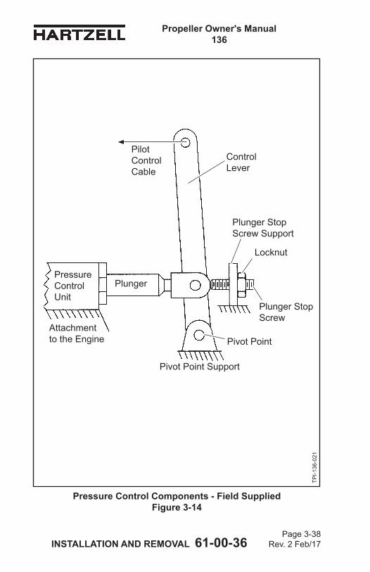
Propeller Owner's Manual 136
INSTALLATION AND REMOVAL 61-00-36 Page 3-38
Rev. 2 Feb/17
Pressure Control Components - Field Supplied Figure 3-14
TPI-1
36-0
21
Pilot Control Cable
Plunger Stop Screw Support
Locknut
Plunger Stop Screw
Pivot Point
Pivot Point Support
PlungerPressure Control Unit
Attachment to the Engine
Control Lever
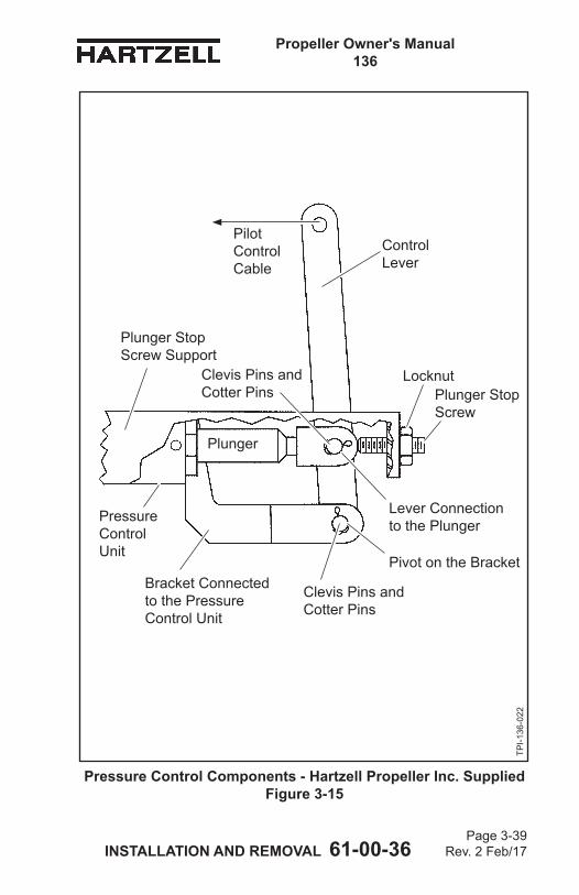
Propeller Owner's Manual 136
INSTALLATION AND REMOVAL 61-00-36 Page 3-39
Rev. 2 Feb/17
Pressure Control Components - Hartzell Propeller Inc. Supplied Figure 3-15
TPI-1
36-0
22
Pilot Control Cable
Plunger Stop Screw Support
LocknutPlunger Stop Screw
Pivot on the BracketBracket Connected to the Pressure Control Unit
Plunger
Pressure Control Unit
Control Lever
Clevis Pins and Cotter Pins
Clevis Pins and Cotter Pins
Lever Connection to the Plunger
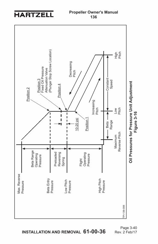
Propeller Owner's Manual 136
INSTALLATION AND REMOVAL 61-00-36 Page 3-40
Rev. 2 Feb/17
Hig
h P
itch
Con
stan
t S
peed
Bet
a
Ran
geLo
w
Pitc
hM
axim
um
Rev
erse
Pitc
h
Dec
reas
ing
Pitc
h
Hig
h P
itch
Pre
ssur
e
Low
Pitc
h P
ress
ure
Bet
a E
ntry
P
ress
ure
Max
. Rev
erse
P
ress
ure
Bet
a R
ange
O
pera
ting
Pre
ssur
e
Pre
load
ed
Rev
ersi
ng
Spr
ing
Flig
ht
Ope
ratin
g P
ress
ure
Incr
easi
ng
Pitc
h
TPI-1
36-0
06
Oil
Pres
sure
s fo
r Pre
ssur
e U
nit A
djus
tmen
t Fi
gure
3-1
6
Pos
ition
2
Pos
ition
1
10-2
0 ps
i
Pos
ition
3
Fixe
d O
il P
ress
ure
Atte
nuat
ion
Valv
e
(Plu
nger
Sto
p S
crew
Loc
atio
n)
Pos
ition
4
Propeller Owner's Manual 136
INSTALLATION AND REMOVAL 61-00-36 Page 3-41
Rev. 2 Feb/17
C. Installing the Pressure Control Unit and the Governor(1) With the raised screen pointing away from the engine
mounting pad, install the B-1104 governor gasket over the four studs, making sure that the screened slot and oilflowholesinthegovernorgasketcorrectlyalignwiththe oil holes in the governor mounting pad of the engine. Refer to Figure 3-10. (a) Oneoilflowholeinthegovernorgasketmaynotbe
needed.(2) Withthe(round)flangepointing toward the engine
governor mounting pad, install the pressure control unit. Refer to Figure 3-7 and Figure 3-8. (a) The pressure control unit will only install in one of
four possible orientations.(b) Make sure that the pressure control unit, control
lever, and pressure gauge port align with the aircraft fittings.
(3) With the raised screen pointing away from the pressure control unit, install a second B-1104 governor gasket overthefourstuds,makingsurethattheoilflowholesin the pressure control unit correctly align with the screenedslotandoilflowholesintheB-1104 governor gasket.
(4) Install the governor over the four studs.(a) Make sure that the semicircular screen in the B-1104
governor gasket aligns with the semicircular groove in the governor base and that the oil ports of the governor correctly align with the pressure control unitandgovernorgasketoilflowholes(s).
(b) Push the four studs through the four holes in the governor until the studs are through the governor flangesurfaceandawasherandnutcanbeinstalled.
(5) Install a B-3851-0563 washer on each of the four studs.(6) Turn a B-3808-5 self-locking hex nut on each stud.
Propeller Owner's Manual 136
INSTALLATION AND REMOVAL 61-00-36 Page 3-42
Rev. 2 Feb/17
(7) Torque each B-3808-5 self-locking hex nut with a torque wrenchandatorqueadapter(thatfitsahexnutthatis1/2inchacrosstheflats)inaccordancewithTable3-1and Figure 3-1.
(8) Attach the RPM control cable to the control arm of the governor.
(9) Attach the pilot control cable (manual reverse thrust operation and maneuvering) to the pressure control unit control lever.
Propeller Owner's Manual 136
INSTALLATION AND REMOVAL 61-00-36 Page 3-43
Rev. 2 Feb/17
D. Pressure Control Unit Adjustment(1) After installation of the propeller, pressure control unit,
and governor, the pressure control unit will require adjustment for correct operation of the propeller. (a) The adjustment instructions assume that the
governor RPM control has been connected to the cockpit control and that any maximum RPM adjustments at the governor or cockpit control have been completed.
(2) The distance that the plunger of the pressure control unit is permitted to extend out of the pressure control unit body must be adjusted and secured. (a) The procedure used to determine this distance will
be discussed in the section, “Plunger Stop Screw Adjustment” in this chapter.
(b) This section discusses the additional parts outside the basic pressure control unit that are required and the geometries associated with these parts. 1 The pressure control reversing propeller system
in Figure 2-2, “Pressure Control Reversing Propeller System” in the Description and Operation chapter of this manual shows a bolt or set screw and a locking nut attached to a secure feature to restrain the amount of movement of the plunger away from the pressure control unit body. a If the plunger extends farther out of the
pressure control unit body, it will lower the oil pressure permitted to reach the propeller duringnormalgovernedflight.(1) Reducing this distance will increase
the oil pressure to the propeller during normalgovernedflight.
Propeller Owner's Manual 136
INSTALLATION AND REMOVAL 61-00-36 Page 3-44
Rev. 2 Feb/17
2 Figure 2-2, “Pressure Control Reversing Propeller System” in the Description and Operation chapter of this manual isasimplifiedrepresentation of the pressure control reversing propeller system and does not show some detail and components. a A more accurate representation of the parts
involved with the minimum oil pressure adjustment is shown in Figure 3-14 or Figure 3-15.(1) If installing a pressure control unit that
does not have a plunger stop, pivot point (bracket), or control lever, refer to Figure 3-14. (a) These pressure control units still
require these features and the customer or airframe manufacturer must provide these features or parts.
(2) If installing a pressure control unit with the plunger stop, pivot point (bracket) and lever incorporated into the Hartzell Propeller Inc. supplied pressure control unit, refer to Figure 3-15.
3 A control lever has been introduced to permit the pilot to pull on a cable and push the plunger into the pressure control unit body. a The plunger compresses the pressure
relief compression spring that resists the movement of the plunger into the pressure control unit body. Refer to Figure 2-2, “Pressure Control Reversing Propeller System” in the Description and Operation chapter of this manual.
Propeller Owner's Manual 136
INSTALLATION AND REMOVAL 61-00-36 Page 3-45
Rev. 2 Feb/17
4 Thecontrolleverisfirstattachedtoapivotpointthat is secured. a The control lever rotates around the pivot
point that is attached at one end of its length. Refer to Figure 3-14 or Figure 3-15.
5 The second control lever attachment is to the pressure control unit plunger. Refer to Figure 3-14 or Figure 3-15.
6 The third control lever attachment is to the pilot control through a cable. Refer to Figure 3-14 or Figure 3-15.
7 The pressure relief compression spring pushes on the plunger that pushes the control lever away from the pressure control unit until it is stopped by the plunger stop screw. Refer to Figure 2-2, “Pressure Control Reversing Propeller System” in the Description and Operation chapter of this manual and Figure 3-14 or Figure 3-15.
8 Moving the propeller blade angle from low pitch into beta range is done by pulling on the pilot control. a This will pull the lever and plunger away
from the plunger stop screw and increase oil pressure supplied to the propeller.
9 Determination of the adjustment location of the plunger stop screw is discussed in the section, “Plunger Stop Screw Adjustment” in this chapter.
Propeller Owner's Manual 136
INSTALLATION AND REMOVAL 61-00-36 Page 3-46
Rev. 2 Feb/17
(3) Plunger Stop Screw Adjustment(a) It is necessary to understand the operational
features of the pressure control reversing propeller system to correctly locate the plunger stop screw location of the pressure control unit.1 In the Description and Operation chapter, the
section 1.C.(4) discusses setting the Pressure Control Unit to a pressure attenuation value which will be performed by the plunger stop screw.
(b) Refer to the Description and Operation chapter of this manual for construction, hardware description, and operation. 1 Careful reading and understanding of the
section “Propeller Beta (Reverse) Operation” in the Description and Operation chapter of this manual is required.
2 The section 1.D.(7)(a) addresses the feature of fixedoilpressureattenuationthat is performed by correct location (adjustment) of the plunger stop screw.
(c) The propeller control oil pressures that are shown in Figure 2-3 “Oil Pressures - Pressure Control Reversing Propeller” in the Description and Operation chapter of this manual are reproduced with some additional information as Figure 3-16 in this section. 1 The oil pressure chart in Figure 3-16 will be used
to help understand how to determine where to locate the plunger stop screw to obtain the correctfixedoilpressurereductionfor governed propeller operation.
Propeller Owner's Manual 136
INSTALLATION AND REMOVAL 61-00-36 Page 3-47
Rev. 2 Feb/17
(d) Figure 3-16 shows propeller control oil pressures that are required between the blade angle ranges of high pitch and maximum reverse pitch. 1 The horizontal axis represents the blade angle
of the propeller.2 The vertical axis represents the magnitude of oil
pressure required for propeller control. (e) Between low pitch and high pitch there are two
straight sloped lines that are parallel to each other. Refer to Figure 3-16.1 The lower line represents the oil pressure that
is required for propeller control when the blade angle is increasing.
2 The upper line represents the oil pressure that is required for propeller control when the blade angle is decreasing.
3 The different oil pressures that are required for propeller control at the same blade angle when increasing or decreasing blade angle is caused by friction involved in moving the propeller pitch change components.
4 The oil pressure between low pitch and high pitch, which changes, is caused by the springs in the cylinder of the propeller. Refer to Figure 2-2, “Pressure Control Reversing Propeller System” in the Description and Operation chapter of this manual.
(f) The plunger stop screw must be adjusted get a pressure that is 10 to 20 psi above the low pitch oil pressure that was obtained during a decrease pitch movement of the propeller blades. Refer to Position 3 in Figure 3-16.
Propeller Owner's Manual 136
INSTALLATION AND REMOVAL 61-00-36 Page 3-48
Rev. 2 Feb/17
(g) The preloaded spring in the hub that is between thepropellerbladesandtheengineflange,mustbe overcome by the propeller oil pressure before the blades will move from low pitch to lower blade angles in the beta range. Refer to Figure 2-2, “Pressure Control Reversing Propeller System” in the Description and Operation chapter of this manual and Position 2 in Figure 3-16.
(h) When at low pitch blade angle position it is possible to be at many oil pressures ranging from Position 1 (increasing pitch from low pitch) to Position 2 (decreasing blade pitch into beta range). Refer to Figure 3-16.
(i) The plunger stop screw is to be adjusted to get an oil pressure at Position 3 that is 10 to 20 psi above the oil pressure that it takes to reach low pitch position during decreasing pitch, which is shown as Position 4. Refer to Figure 3-16.
(j) The installed cockpit mounted oil pressure gauge is shown in Figure 2-2, “Pressure Control Reversing Propeller System” in the Description and Operation chapter of this manual and discussed in the Description and Operation chapter. 1 The pressure range recommended is
0 to 300 psi. 2 The purpose is to monitor that the oil pressure
reduction value is still at Position 3 before eachflight.a This is to make sure that the governor has
sufficientoilpressureavailableforbladeanglecontrolduringgovernedflightandthatthe oil pressure is not so high, oil pressure above Position 2, that accidental entry into beta range might occur.
Propeller Owner's Manual 136
INSTALLATION AND REMOVAL 61-00-36 Page 3-49
Rev. 2 Feb/17
(k) Position 4 at low pitch blade angle must be determined. 1 The objective is to determine what oil pressure
is required to just reach low pitch blade angle during decreasing blade pitch.
2 The blade model, counterweights, cylinder mounted springs, and friction resisting blade movement will affect the oil pressure required to reach low pitch blade angle.
3 The cockpit mounted oil pressure gauge will be monitored to identify the Position 4 oil pressure.
(l) Determine the Position 4 oil pressure:1 Before starting the engine, adjust the plunger
stop screw away from the plunger. Refer to Figure 3-14 or Figure 3-15.a This will make sure that the oil pressure will
be lower than required.b With the aircraft static on the ground start
the engine at idle power. c Select maximum RPM with the governor
RPM control. d Increase engine power (throttle) slowly until
reaching 1200 to 1400 RPM. e Now move the pilot control in the cockpit to
push the plunger into the pressure control unit and get an oil pressure of 100 PSI for thefirstefforttodeterminethePosition4oilpressure value.
f Continue increasing engine power (throttle) slowly to maximum power.
Propeller Owner's Manual 136
INSTALLATION AND REMOVAL 61-00-36 Page 3-50
Rev. 2 Feb/17
(m) If the engine RPM reaches maximum before reaching maximum power, then the governor was activated to increase blade angle to stop the RPM increase and will have dropped the oil pressure shown on the cockpit mounted oil pressure gauge to a Position 1 location or lower. Refer to Figure 3-16. 1 This is not a true indication of the oil pressure
permitted by the pressure control unit. 2 Repeat step 4.D.(3)(l) and move the pilot control
in the cockpit to push the plunger into the pressure control unit and obtain an oil pressure that is increased 10 PSI from the previous effort.
(n) If the engine RPM does not reach the maximum RPM permitted by the governor, then move the pilot control to push the plunger farther into the pressure control unit and slowly increase oil pressure above the previously selected oil pressure until the resultant increase of RPM just reaches maximum RPM. 1 This is the Position 4 oil pressure. Refer to
Figure 3-16.2 Move the pilot control to obtain an additional
10 to 15 PSI increase. 3 This is Position 3 oil pressure value. Refer to
Figure 3-16. a Record this pressure value in the propeller
logbook.4 Lock the pilot control in place to permit later
examination of the pressure control unit plunger location after the engine is shut down.
5 Shut down the engine.
Propeller Owner's Manual 136
INSTALLATION AND REMOVAL 61-00-36 Page 3-51
Rev. 2 Feb/17
(o) The pressure control unit plunger was repositioned into the pressure control unit by the pilot control and control lever. Refer to Figure 3-14 or Figure 3-15. 1 Release the locknut on the plunger stop screw
and turn the plunger stop screw toward the new location of the pressure control unit plunger until it contacts the pressure control unit plunger.
2 Apply threadlocker CM152 to the interface between the locknut and the plunger stop screw and mechanically jam the lock nut onto the plunger stop screw and against the plunger stop screw support.
(p) Determine that the Position 3 oil pressure is still the same. Refer to Figure 3-16.1 With the aircraft static on the ground, start the
engine at idle power. 2 Select maximum RPM with the governor RPM
control. 3 Increase engine power (throttle) slowly until
reaching 1200 to 1400 RPM. 4 The oil pressure value on the oil pressure gauge
should be the same Position 3 oil pressure as previously obtained. Refer to Figure 2-2 and Figure 3-16.
5 Minor plunger stop screw positional changes are permitted to obtain the previously determined Position 3, oil pressure value. Refer to Figure 3-16.
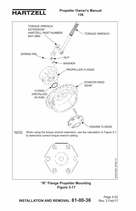
Propeller Owner's Manual 136
INSTALLATION AND REMOVAL 61-00-36 Page 3-52
Rev. 2 Feb/17
“R” Flange Propeller Mounting Figure 3-17
TORQUE WRENCH
AP
S61
60D
, AP
S61
72
*NOTE: When using the torque wrench extension, use the calculation in Figure 3-1 to determine correct torque wrench setting
PROPELLER FLANGE
STARTER RING GEAR
ENGINE FLANGE
O-RING (INSTALLED
IN HUB)
WASHER
TORQUE WRENCH EXTENSION* HARTZELL PART NUMBER BST-2860
NUTSPRING PIN
Propeller Owner's Manual 136
INSTALLATION AND REMOVAL 61-00-36 Page 3-53
Rev. 2 Feb/17
WARNING: FAILURE TO FOLLOW THESE INSTALLATION INSTRUCTIONS MAY LEAD TO PROPELLER DAMAGE, ENGINE DAMAGE, OR PROPELLER FAILURE, WHICH MAY RESULT IN DEATH, SERIOUS BODILY INJURY, AND/OR SUBSTANTIAL PROPERTY DAMAGE. UNUSUAL OR ABNORMAL VIBRATION DEMANDS IMMEDIATE INSPECTION FOR IMPROPER PROPELLER INSTALLATION. PROPELLER SEPARATION MAY OR MAY NOT BE PROCEEDED BY VIBRATION.
6. Propeller InstallationA. Flange Description
(1) Compact propellers are manufactured with six basic hub mountingflangedesigns.Theflangetypedesignatorsare D, F, K, L, N, or R.
(2) Theflangetypeusedonaparticularpropellerinstallationis indicated in the propeller model stamped on the hub. For example, HC-E3YR-7indicatesan“R”flange.
(3) RefertoAluminumHubPropellerModelIdentificationinthe Description and Operation Chapter of this manual for descriptionofeachflangetype.Asample“R”flangeisalso shown in Figure 3-17.
B. Installation of “R” Flange Propellers
CAUTION: INSTRUCTIONS AND PROCEDURES IN THIS SECTION MAY INVOLVE PROPELLER CRITICAL PARTS. REFER TO THE INTRODUCTION CHAPTER OF THIS MANUAL FOR INFORMATION ABOUT PROPELLER CRITICAL PARTS. REFER TO THE ILLUSTRATED PARTS LIST CHAPTER OF THE APPLICABLE OVERHAUL MANUAL(S) FOR THE IDENTIFICATION OF SPECIFIC PROPELLER CRITICAL PARTS.
(1) General(a) An“R”flangeisanSAENo.2flangethathassix
1/2inchstudsconfiguredina4.75inchcircle.
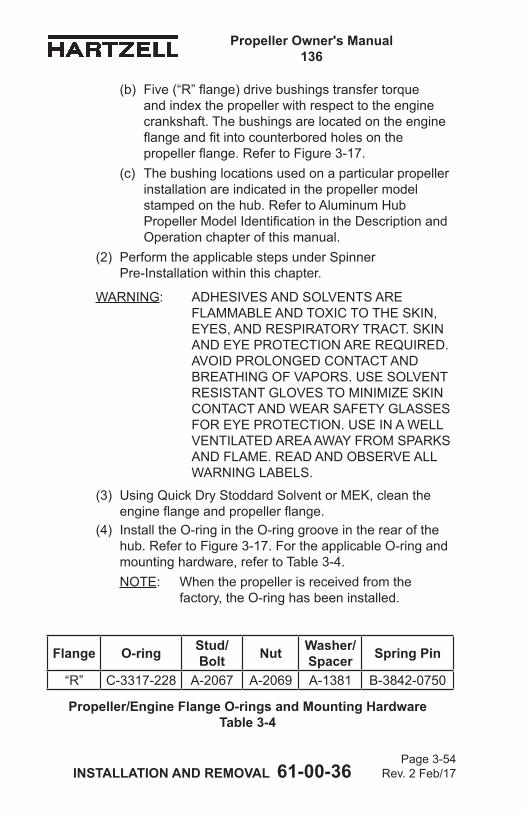
Propeller Owner's Manual 136
INSTALLATION AND REMOVAL 61-00-36 Page 3-54
Rev. 2 Feb/17
(b) Five(“R”flange)drivebushingstransfertorqueand index the propeller with respect to the engine crankshaft. The bushings are located on the engine flangeandfitintocounterboredholesonthepropellerflange.RefertoFigure3-17.
(c) The bushing locations used on a particular propeller installation are indicated in the propeller model stamped on the hub. Refer to Aluminum Hub PropellerModelIdentificationintheDescriptionandOperation chapter of this manual.
(2) Perform the applicable steps under Spinner Pre-Installation within this chapter.
WARNING: ADHESIVES AND SOLVENTS ARE FLAMMABLE AND TOXIC TO THE SKIN, EYES, AND RESPIRATORY TRACT. SKIN AND EYE PROTECTION ARE REQUIRED. AVOID PROLONGED CONTACT AND BREATHING OF VAPORS. USE SOLVENT RESISTANT GLOVES TO MINIMIZE SKIN CONTACT AND WEAR SAFETY GLASSES FOR EYE PROTECTION. USE IN A WELL VENTILATED AREA AWAY FROM SPARKS AND FLAME. READ AND OBSERVE ALL WARNING LABELS.
(3) Using Quick Dry Stoddard Solvent or MEK, clean the engineflangeandpropellerflange.
(4) Install the O-ring in the O-ring groove in the rear of the hub. Refer to Figure 3-17. For the applicable O-ring and mounting hardware, refer to Table 3-4.NOTE: When the propeller is received from the
factory, the O-ring has been installed.
Propeller/Engine Flange O-rings and Mounting Hardware Table 3-4
Flange O-ring Stud/Bolt Nut Washer/
Spacer Spring Pin
“R” C-3317-228 A-2067 A-2069 A-1381 B-3842-0750
Propeller Owner's Manual 136
INSTALLATION AND REMOVAL 61-00-36 Page 3-55
Rev. 2 Feb/17
WARNING: MAKE SURE THAT ANY EQUIPMENT USED TO INSTALL THE PROPELLER IS RATED UP TO 800 LBS. (363 KG) TO SUPPORT THE WEIGHT OF THE PROPELLER ASSEMBLY DURING INSTALLATION. ONE PERSON MUST NEVER ATTEMPT TO INSTALL AN UNSUPPORTED PROPELLER BY HIMSELF, REGARDLESS OF THE SIZE OR WEIGHT OF THE PROPELLER. MANUALLY LIFTING THE PROPELLER ONTO THE ENGINE CAN RESULT IN PERSONAL INJURY.
CAUTION 1: A PROPELLER MUST BE CORRECTLY SUPPORTED DURING INSTALLATION ON THE ENGINE. AVOID ANY ROCKING OR SHIFTING OF THE PROPELLER WHEN IT IS PARTIALLY ENGAGED WITH THE ENGINE. ROCKING OF THE PROPELLER DURING PROPELLER INSTALLATION CAN DAMAGE THE PROPELLER HUB MOUNTING FACE, CAUSING ACTUATION OIL LEAKAGE OR DAMAGE THAT MAY SCRAP THE HUB. HUB DAMAGE CAN ALSO INTRODUCE METAL INTO THE PROPELLER OIL ACTUATION SYSTEM, WHICH COULD POSSIBLY DAMAGE THE ENGINE.
CAUTION 2: WHEN INSTALLING THE PROPELLER ON THE AIRCRAFT, DO NOT DAMAGE THE ICE PROTECTION SYSTEM COMPONENTS, IF APPLICABLE.
(5) With a suitable support, such as a crane hoist or similar equipment, carefully move the propeller assembly to theaircraftenginemountingflangeinpreparationforinstallation.
(6) Installthepropellerontheengineflange.Aligntheengineflangebushingswiththecorrespondingholesinthepropellerflange.
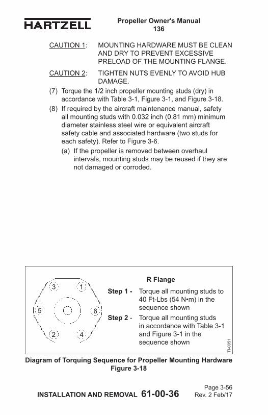
Propeller Owner's Manual 136
INSTALLATION AND REMOVAL 61-00-36 Page 3-56
Rev. 2 Feb/17
CAUTION 1: MOUNTING HARDWARE MUST BE CLEAN AND DRY TO PREVENT EXCESSIVE PRELOAD OF THE MOUNTING FLANGE.
CAUTION 2: TIGHTEN NUTS EVENLY TO AVOID HUB DAMAGE.
(7) Torque the 1/2 inch propeller mounting studs (dry) in accordance with Table 3-1, Figure 3-1, and Figure 3-18.
(8) If required by the aircraft maintenance manual, safety all mounting studs with 0.032 inch (0.81 mm) minimum diameter stainless steel wire or equivalent aircraft safety cable and associated hardware (two studs for each safety). Refer to Figure 3-6.(a) If the propeller is removed between overhaul
intervals, mounting studs may be reused if they are not damaged or corroded.
Diagram of Torquing Sequence for Propeller Mounting Hardware Figure 3-18
1
2
3
4
5 6
R FlangeStep 1 - Torque all mounting studs to
40 Ft-Lbs (54 N•m) in the sequence shown
Step 2 - Torque all mounting studs in accordance with Table 3-1 and Figure 3-1 in the sequence shown
TI-0
051
Propeller Owner's Manual 136
INSTALLATION AND REMOVAL 61-00-36 Page 3-57
Rev. 2 Feb/17
(9) If the propeller is equipped with an ice protection system that uses components supplied by Hartzell Propeller Inc., applicable instructions and technical information for the components supplied by Hartzell Propeller Inc. can be found in the following publications available on the Hartzell Propeller Inc. website at www.hartzellprop.com: (a) Hartzell Propeller Inc. Manual 180 (30-61-80) -
Propeller Ice Protection System Manual(b) Hartzell Propeller Inc. Manual 181 (30-60-81) -
Propeller Ice Protection System Component Maintenance Manual
(c) Hartzell Propeller Inc. Manual 182 (61-12-82) - Propeller Electrical De-ice Boot Removal and Installation Manual
(d) Hartzell Propeller Inc. Manual 183 (61-12-83) - Propeller Anti-icing Boot Removal and Installation Manual
(10) Propeller ice protection system components not supplied by Hartzell Propeller Inc. are controlled by the applicable TC or STC holder’s Instructions for Continued Airworthiness (ICA).
(11) Install the propeller spinner dome in accordance with the section, “Spinner Installation” in this chapter.
Propeller Owner's Manual 136
INSTALLATION AND REMOVAL 61-00-36 Page 3-58
Rev. 2 Feb/17
7. Spinner Dome Installation
CAUTION 1: TO PREVENT DAMAGE TO THE BLADE AND BLADE PAINT, WRAP THE BLADE SHANKS IN SEVERAL LAYERS OF MASKING OR DUCT TAPE BEFORE INSTALLING THE SPINNER DOME. REMOVE THE TAPE AFTER THE SPINNER IS INSTALLED.
CAUTION 2: THE SPINNER DOME WILL WOBBLE IF NOT ALIGNED CORRECTLY. THIS COULD AFFECT THE DYNAMIC BALANCE OF THE PROPELLER.
A. General(1) The following instructions apply to Hartzell Propeller Inc.
spinners only. In some cases, the airframe manufacturer produced the spinner assembly. If so, refer to the airframe manufacturer’s manual for spinner installation instructions.
B. Installing the Spinner Dome(1) Examine the interior of the spinner dome. If the spinner
dome has a forward bulkhead that encircles the propeller cylinder, the cylinder may need to be wrapped with one or more layers of UHMW tape (Hartzell Propeller Inc. P/N B-6654-100).
CAUTION: THE SPINNER DOME INTERNAL SUPPORT MUST FIT SNUGLY ON THE CYLINDER. AN INCORRECTLY SUPPORTED DOME COULD CAUSE CYLINDER DAMAGE OR A CRACK IN THE DOME OR BULKHEAD.
(2) Installthespinnerdomeandexamineforasnugfitwhere the internal support contacts the cylinder. (a) Ifthesupportdoesnotfitsnuglyonthecylinder,
apply a layer of UHMW tape and re-examine. (b) Repeatuntilthespinnersupportfitssnuglyon
the cylinder.
Propeller Owner's Manual 136
INSTALLATION AND REMOVAL 61-00-36 Page 3-59
Rev. 2 Feb/17
CAUTION: TO AVOID DAMAGING THE AIRCRAFT COWLING, THE SCREWS MUST NOT EXTEND MORE THAN THREE THREADS PAST THE BULKHEAD NUTPLATES.
(3) Attach the spinner dome to the spinner bulkhead or to the adapter ring with the supplied screws and washers. Refer to Table 3-5.(a) When the spinner dome has been removed during
maintenance,examinethefitofthespinnerforwardbulkhead to the cylinder.
(b) If the spinner dome loosens in service, add one or more layers of UHMW tape to the cylinder until the spinnerdomefitssnugly.
8. Post-Installation ChecksA. Perform Static RPM Check as outlined in the Testing and
Troubleshooting chapter in this manual.
Propeller Owner's Manual 136
INSTALLATION AND REMOVAL 61-00-36 Page 3-60
Rev. 2 Feb/17
(This page is intentionally blank.)
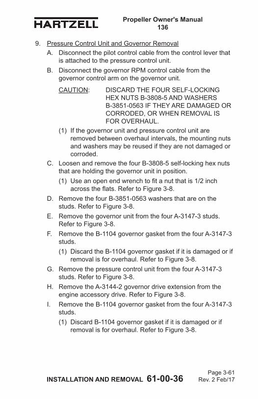
Propeller Owner's Manual 136
INSTALLATION AND REMOVAL 61-00-36 Page 3-61
Rev. 2 Feb/17
9. Pressure Control Unit and Governor RemovalA. Disconnect the pilot control cable from the control lever that
is attached to the pressure control unit.B. Disconnect the governor RPM control cable from the
governor control arm on the governor unit.
CAUTION: DISCARD THE FOUR SELF-LOCKING HEX NUTS B-3808-5 AND WASHERS B-3851-0563 IF THEY ARE DAMAGED OR CORRODED, OR WHEN REMOVAL IS FOR OVERHAUL.
(1) If the governor unit and pressure control unit are removed between overhaul intervals, the mounting nuts and washers may be reused if they are not damaged or corroded.
C. Loosen and remove the four B-3808-5 self-locking hex nuts that are holding the governor unit in position. (1) Useanopenendwrenchtofitanutthatis1/2inch
acrosstheflats.RefertoFigure3-8.D. Remove the four B-3851-0563 washers that are on the
studs. Refer to Figure 3-8.E. Remove the governor unit from the four A-3147-3 studs.
Refer to Figure 3-8.F. Remove the B-1104 governor gasket from the four A-3147-3
studs. (1) Discard the B-1104 governor gasket if it is damaged or if
removal is for overhaul. Refer to Figure 3-8.G. Remove the pressure control unit from the four A-3147-3
studs. Refer to Figure 3-8.H. Remove the A-3144-2 governor drive extension from the
engine accessory drive. Refer to Figure 3-8.I. Remove the B-1104 governor gasket from the four A-3147-3
studs. (1) Discard B-1104 governor gasket if it is damaged or if
removal is for overhaul. Refer to Figure 3-8.
Propeller Owner's Manual 136
INSTALLATION AND REMOVAL 61-00-36 Page 3-62
Rev. 2 Feb/17
J. Examine each of the four A-3147-3 studs for damage or corrosion. (1) Remove and replace any stud that is damaged or
corroded.K. Use a plastic tool to remove remaining gasket material that is
on the governor unit base, either side of the pressure control unit, or the governor mounting pad surface on the engine.
Propeller Owner's Manual 136
INSTALLATION AND REMOVAL 61-00-36 Page 3-63
Rev. 2 Feb/17
10. Spinner Removal
CAUTION: WRAP THE BLADE SHANKS IN SEVERAL LAYERS OF MASKING OR DUCT TAPE BEFORE REMOVING THE SPINNER DOME TO PREVENT DAMAGING THE BLADE AND BLADE PAINT.
A. Removal of the Spinner(1) Remove the screws and washers that attach the spinner
dome to the spinner bulkhead or adapter ring.(2) Remove the spinner dome.
B. Hub Mounted Spinner Bulkhead Removal(1) Remove propeller. Refer to Propeller Removal in this
chapter.(2) Removetheflatwashersandself-lockingnutsthat
attach the spinner bulkhead to the propeller hub. Remove the spinner bulkhead.
(3) Reinstalltheflatwashersandself-lockingnutsthatwereremoved during the spinner bulkhead removal.
Propeller Owner's Manual 136
INSTALLATION AND REMOVAL 61-00-36 Page 3-64
Rev. 2 Feb/17
11. Propeller RemovalA. Removal of “R” Flange Propellers
(1) Remove the spinner dome in accordance with the Spinner Removal procedures in this chapter.
(2) If the propeller is equipped with an ice protection system that uses components supplied by Hartzell Propeller Inc., applicable instructions and technical information for the components supplied by Hartzell Propeller Inc. can be found in the following publications available on the Hartzell Propeller Inc. website at www.hartzellprop.com:(a) Hartzell Propeller Inc. Manual 180 (30-61-80) -
Propeller Ice Protection System Manual (b) Hartzell Propeller Inc. Manual 181 (30-60-81) -
Propeller Ice Protection System Component Maintenance Manual
(c) Hartzell Propeller Inc. Manual 182 (61-12-82) - Propeller Electrical De-Ice Boot Removal and Installation Manual
(d) Hartzell Propeller Inc. Manual 183 (61-12-83) - Propeller Anti-Icing Boot Removal and Installation Manual
(3) Propeller ice protection system components not supplied by Hartzell Propeller Inc. are controlled by the applicable TC or STC holder’s Instructions for Continued Airworthiness (ICA).
(4) If installed, cut and remove the safety wire or safety cable on the propeller mounting stud nuts.
WARNING: MAKE SURE THE SLING IS RATED UP TO 800 LBS. (363 KG) TO SUPPORT THE WEIGHT OF THE PROPELLER ASSEMBLY DURING REMOVAL.
(5) Support the propeller assembly with a sling.
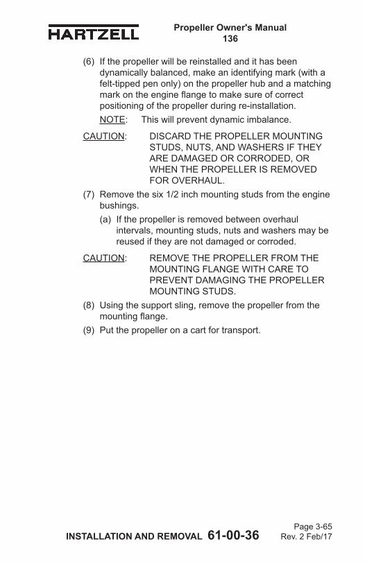
Propeller Owner's Manual 136
INSTALLATION AND REMOVAL 61-00-36 Page 3-65
Rev. 2 Feb/17
(6) If the propeller will be reinstalled and it has been dynamically balanced, make an identifying mark (with a felt-tipped pen only) on the propeller hub and a matching markontheengineflangetomakesureofcorrectpositioning of the propeller during re-installation.NOTE: This will prevent dynamic imbalance.
CAUTION: DISCARD THE PROPELLER MOUNTING STUDS, NUTS, AND WASHERS IF THEY ARE DAMAGED OR CORRODED, OR WHEN THE PROPELLER IS REMOVED FOR OVERHAUL.
(7) Remove the six 1/2 inch mounting studs from the engine bushings.(a) If the propeller is removed between overhaul
intervals, mounting studs, nuts and washers may be reused if they are not damaged or corroded.
CAUTION: REMOVE THE PROPELLER FROM THE MOUNTING FLANGE WITH CARE TO PREVENT DAMAGING THE PROPELLER MOUNTING STUDS.
(8) Using the support sling, remove the propeller from the mountingflange.
(9) Put the propeller on a cart for transport.

Propeller Owner's Manual 136
INSTALLATION AND REMOVAL 61-00-36 Page 3-66
Rev. 2 Feb/17
(This page is intentionally blank.)
Propeller Owner's Manual 136
TESTING AND TROUBLESHOOTING 61-00-36 Page 4-1
Rev. 2 Feb/17
TESTING AND TROUBLESHOOTING - CONTENTS
1. Operational Tests .......................................................................4-3A. General ..............................................................................4-3B. Initial Run-Up to Purge Trapped Air ...................................4-3C. Beta Range Operation Check ............................................4-4D. Governor Operation Check ................................................4-4E. Static RPM Check .............................................................4-5F. Oil Leakage Check ............................................................4-6
2. Propeller Ice Protection Systems ...............................................4-6A. Electric De-ice System ......................................................4-6B. Anti-ice System ..................................................................4-6
3. Troubleshooting ..........................................................................4-7A. Hunting and Surging ..........................................................4-7B. Engine/Propeller Speed Varies with Airspeed ...................4-8C. Engine/Propeller Speed Increases With Increasing
Engine Power And Decreases With Decreasing Engine Power ....................................................................4-9
D. Governor RPM Control of Engine/Propeller Speed Has Little or No Effect ...............................................................4-9
E. Propeller Underspeed ......................................................4-10F. Propeller Overspeed ........................................................4-11G. Beta Range Operation .....................................................4-12H. Vibration ..........................................................................4-13I. Oil or Grease Leakage ....................................................4-15
Propeller Owner's Manual 136
TESTING AND TROUBLESHOOTING 61-00-36 Page 4-2
Rev. 2 Feb/17
(This page is intentionally blank.)
Propeller Owner's Manual 136
TESTING AND TROUBLESHOOTING 61-00-36 Page 4-3
Rev. 2 Feb/17
1. Operational Tests
CAUTION: INSTRUCTIONS AND PROCEDURES IN THIS SECTION MAY INVOLVE PROPELLER CRITICAL PARTS. REFER TO THE INTRODUCTION CHAPTER OF THIS MANUAL FOR INFORMATION ABOUT PROPELLER CRITICAL PARTS. REFER TO THE ILLUSTRATED PARTS LIST CHAPTER OF THE APPLICABLE OVERHAUL MANUAL(S) FOR THE IDENTIFICATION OF SPECIFIC PROPELLER CRITICAL PARTS.
A. General(1) The propeller must be installed on an application that
uses a propeller governor.(2) Perform the test after propeller installation and before
every flight.(3) The propeller system must be purged of air and correct
operation verified.B. Initial Run-Up to Purge Trapped Air
(1) Perform engine start and warm-up in accordance with the Pilot's Operating Handbook (POH).
CAUTION: AIR TRAPPED IN THE PROPELLER HYDRAULIC SYSTEM WILL CAUSE THE PITCH CONTROL TO BE IMPRECISE AND MAY RESULT IN PROPELLER SURGING.
(2) Cycle the propeller control throughout its operating range from low to high blade pitch (or as directed by the POH).
(3) Repeat this procedure at least three times to purge air from the propeller hydraulic system and to introduce warmed oil to the cylinder.NOTE: Pitch change response on the first operation
from low to high blade pitch may be slow, but should speed up on the second and third cycles.
(4) Shut down the engine in accordance with the POH.
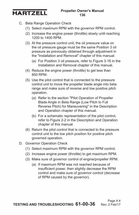
Propeller Owner's Manual 136
TESTING AND TROUBLESHOOTING 61-00-36 Page 4-4
Rev. 2 Feb/17
C. Beta Range Operation Check(1) Select maximum RPM with the governor RPM control.(2) Increase the engine power (throttle) slowly until reaching
1200 to 1400 RPM.(3) At the pressure control unit, the oil pressure value on
the oil pressure gauge must be the same Position 3 oil pressure as previously obtained through adjustment in the "Installation and Removal" chapter of this manual. (a) For Position 3 oil pressure, refer to Figure 3-16 in the
Installation and Removal chapter of this manual.(4) Reduce the engine power (throttle) to get less than
850 RPM. (5) Use the pilot control that is connected to the pressure
control unit to move the propeller blade angle into beta range and make sure of reverse and low positive pitch operation.(a) Refer to the section "Pilot Operation of Propeller
Blade Angle in Beta Range (Low Pitch to Full Reverse Pitch) for Maneuvering" in the Description and Operation chapter of this manual.
(b) For a schematic representation of the pilot control, refer to Figure 2-2 in the Description and Operation chapter of this manual.
(6) Return the pilot control that is connected to the pressure control unit to the low pitch position for positive pitch governed operation.
D. Governor Operation Check(1) Select maximum RPM with the governor RPM control.(2) Increase engine power (throttle) to get maximum RPM.(3) Make sure of governor control of engine/propeller RPM.
(a) If maximum RPM was not reached because of insufficient power, then slightly decrease the RPM control and make sure of governor control (decrease of RPM caused by the governor).
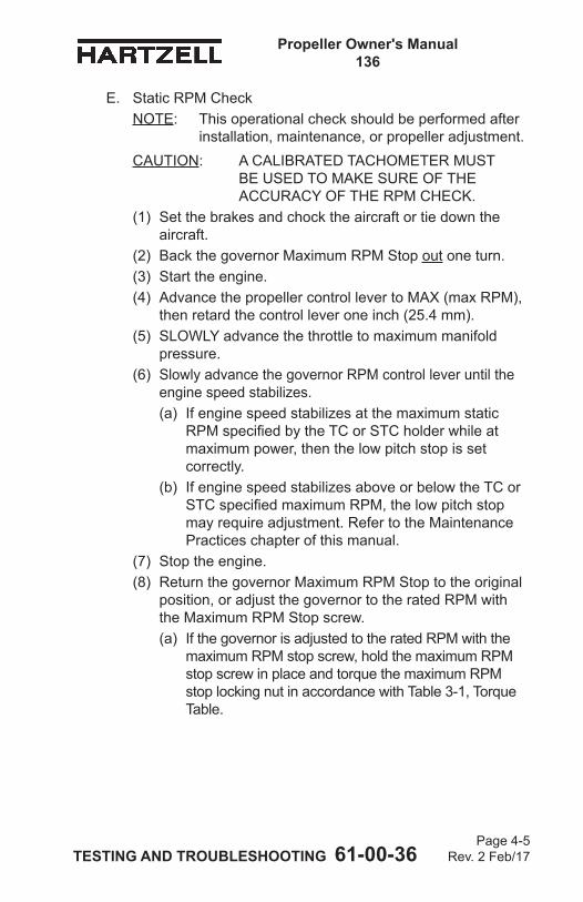
Propeller Owner's Manual 136
TESTING AND TROUBLESHOOTING 61-00-36 Page 4-5
Rev. 2 Feb/17
E. Static RPM CheckNOTE: This operational check should be performed after
installation, maintenance, or propeller adjustment.CAUTION: A CALIBRATED TACHOMETER MUST
BE USED TO MAKE SURE OF THE ACCURACY OF THE RPM CHECK.
(1) Set the brakes and chock the aircraft or tie down the aircraft.
(2) Back the governor Maximum RPM Stop out one turn.(3) Start the engine.(4) Advance the propeller control lever to MAX (max RPM),
then retard the control lever one inch (25.4 mm).(5) SLOWLY advance the throttle to maximum manifold
pressure.(6) Slowly advance the governor RPM control lever until the
engine speed stabilizes.(a) If engine speed stabilizes at the maximum static
RPM specified by the TC or STC holder while at maximum power, then the low pitch stop is set correctly.
(b) If engine speed stabilizes above or below the TC or STC specified maximum RPM, the low pitch stop may require adjustment. Refer to the Maintenance Practices chapter of this manual.
(7) Stop the engine.(8) Return the governor Maximum RPM Stop to the original
position, or adjust the governor to the rated RPM with the Maximum RPM Stop screw.(a) If the governor is adjusted to the rated RPM with the
maximum RPM stop screw, hold the maximum RPM stop screw in place and torque the maximum RPM stop locking nut in accordance with Table 3-1, Torque Table.
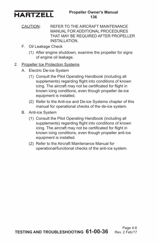
Propeller Owner's Manual 136
TESTING AND TROUBLESHOOTING 61-00-36 Page 4-6
Rev. 2 Feb/17
CAUTION: REFER TO THE AIRCRAFT MAINTENANCE MANUAL FOR ADDITIONAL PROCEDURES THAT MAY BE REQUIRED AFTER PROPELLER INSTALLATION.
F. Oil Leakage Check(1) After engine shutdown, examine the propeller for signs
of engine oil leakage.
2. Propeller Ice Protection SystemsA. Electric De-ice System
(1) Consult the Pilot Operating Handbook (including all supplements) regarding flight into conditions of known icing. The aircraft may not be certificated for flight in known icing conditions, even though propeller de-ice equipment is installed.
(2) Refer to the Anti-ice and De-ice Systems chapter of this manual for operational checks of the de-ice system.
B. Anti-ice System(1) Consult the Pilot Operating Handbook (including all
supplements) regarding flight into conditions of known icing. The aircraft may not be certificated for flight in known icing conditions, even though propeller anti-ice equipment is installed.
(2) Refer to the Aircraft Maintenance Manual for operational/functional checks of the anti-ice system.
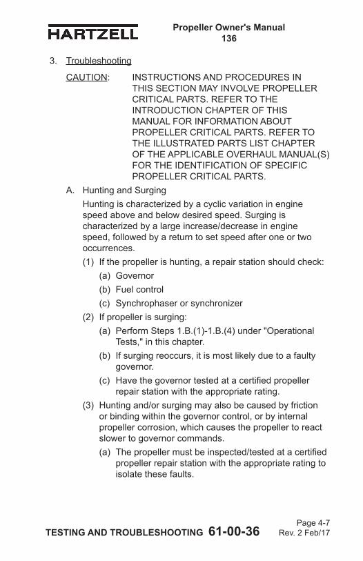
Propeller Owner's Manual 136
TESTING AND TROUBLESHOOTING 61-00-36 Page 4-7
Rev. 2 Feb/17
3. Troubleshooting
CAUTION: INSTRUCTIONS AND PROCEDURES IN THIS SECTION MAY INVOLVE PROPELLER CRITICAL PARTS. REFER TO THE INTRODUCTION CHAPTER OF THIS MANUAL FOR INFORMATION ABOUT PROPELLER CRITICAL PARTS. REFER TO THE ILLUSTRATED PARTS LIST CHAPTER OF THE APPLICABLE OVERHAUL MANUAL(S) FOR THE IDENTIFICATION OF SPECIFIC PROPELLER CRITICAL PARTS.
A. Hunting and SurgingHunting is characterized by a cyclic variation in engine speed above and below desired speed. Surging is characterized by a large increase/decrease in engine speed, followed by a return to set speed after one or two occurrences. (1) If the propeller is hunting, a repair station should check:
(a) Governor(b) Fuel control(c) Synchrophaser or synchronizer
(2) If propeller is surging:(a) Perform Steps 1.B.(1)-1.B.(4) under "Operational
Tests," in this chapter. (b) If surging reoccurs, it is most likely due to a faulty
governor. (c) Have the governor tested at a certified propeller
repair station with the appropriate rating.(3) Hunting and/or surging may also be caused by friction
or binding within the governor control, or by internal propeller corrosion, which causes the propeller to react slower to governor commands. (a) The propeller must be inspected/tested at a certified
propeller repair station with the appropriate rating to isolate these faults.
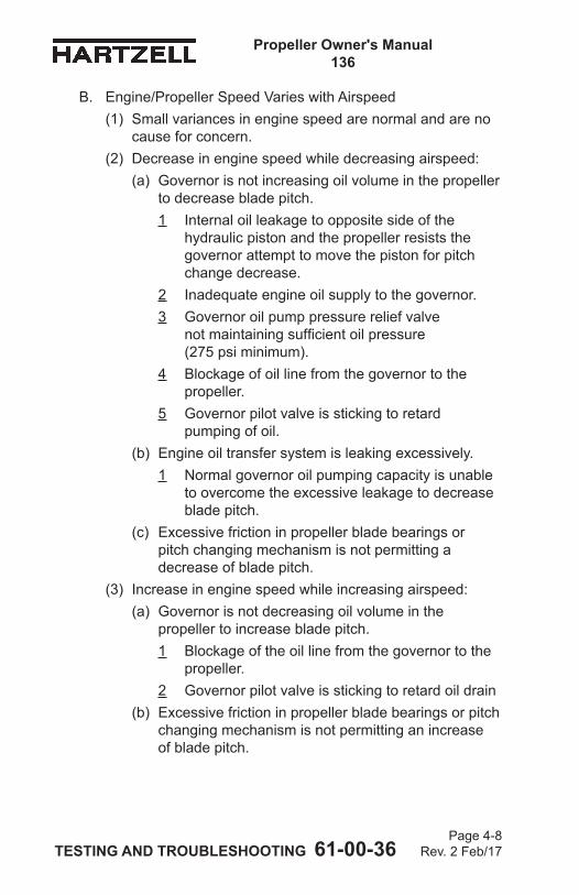
Propeller Owner's Manual 136
TESTING AND TROUBLESHOOTING 61-00-36 Page 4-8
Rev. 2 Feb/17
B. Engine/Propeller Speed Varies with Airspeed(1) Small variances in engine speed are normal and are no
cause for concern.(2) Decrease in engine speed while decreasing airspeed:
(a) Governor is not increasing oil volume in the propeller to decrease blade pitch.1 Internal oil leakage to opposite side of the
hydraulic piston and the propeller resists the governor attempt to move the piston for pitch change decrease.
2 Inadequate engine oil supply to the governor.3 Governor oil pump pressure relief valve
not maintaining sufficient oil pressure (275 psi minimum).
4 Blockage of oil line from the governor to the propeller.
5 Governor pilot valve is sticking to retard pumping of oil.
(b) Engine oil transfer system is leaking excessively.1 Normal governor oil pumping capacity is unable
to overcome the excessive leakage to decrease blade pitch.
(c) Excessive friction in propeller blade bearings or pitch changing mechanism is not permitting a decrease of blade pitch.
(3) Increase in engine speed while increasing airspeed:(a) Governor is not decreasing oil volume in the
propeller to increase blade pitch.1 Blockage of the oil line from the governor to the
propeller.2 Governor pilot valve is sticking to retard oil drain
(b) Excessive friction in propeller blade bearings or pitch changing mechanism is not permitting an increase of blade pitch.
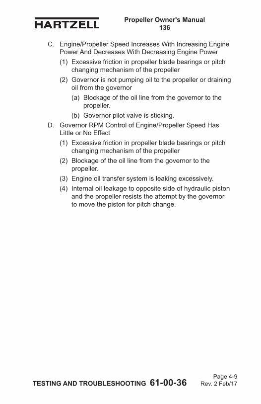
Propeller Owner's Manual 136
TESTING AND TROUBLESHOOTING 61-00-36 Page 4-9
Rev. 2 Feb/17
C. Engine/Propeller Speed Increases With Increasing Engine Power And Decreases With Decreasing Engine Power(1) Excessive friction in propeller blade bearings or pitch
changing mechanism of the propeller(2) Governor is not pumping oil to the propeller or draining
oil from the governor(a) Blockage of the oil line from the governor to the
propeller.(b) Governor pilot valve is sticking.
D. Governor RPM Control of Engine/Propeller Speed Has Little or No Effect(1) Excessive friction in propeller blade bearings or pitch
changing mechanism of the propeller(2) Blockage of the oil line from the governor to the
propeller.(3) Engine oil transfer system is leaking excessively.(4) Internal oil leakage to opposite side of hydraulic piston
and the propeller resists the attempt by the governor to move the piston for pitch change.
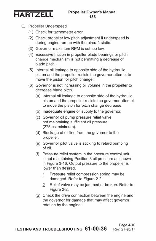
Propeller Owner's Manual 136
TESTING AND TROUBLESHOOTING 61-00-36 Page 4-10
Rev. 2 Feb/17
E. Propeller Underspeed(1) Check for tachometer error.(2) Check propeller low pitch adjustment if underspeed is
during engine run-up with the aircraft static.(3) Governor maximum RPM is set too low.(4) Excessive friction in propeller blade bearings or pitch
change mechanism is not permitting a decrease of blade pitch.
(5) Internal oil leakage to opposite side of the hydraulic piston and the propeller resists the governor attempt to move the piston for pitch change.
(6) Governor is not increasing oil volume in the propeller to decrease blade pitch.(a) Internal oil leakage to opposite side of the hydraulic
piston and the propeller resists the governor attempt to move the piston for pitch change decrease.
(b) Inadequate engine oil supply to the governor.(c) Governor oil pump pressure relief valve
not maintaining sufficient oil pressure (275 psi minimum).
(d) Blockage of oil line from the governor to the propeller.
(e) Governor pilot valve is sticking to retard pumping of oil.
(f) Pressure relief system in the pressure control unit is not maintaining Position 3 oil pressure as shown in Figure 3-16. Output pressure to the propeller is lower than desired.1 Pressure relief compression spring may be
damaged. Refer to Figure 2-2.2 Relief valve may be jammed or broken. Refer to
Figure 2-2.(g) Check the drive connection between the engine and
the governor for damage that may affect governor rotation by the engine.
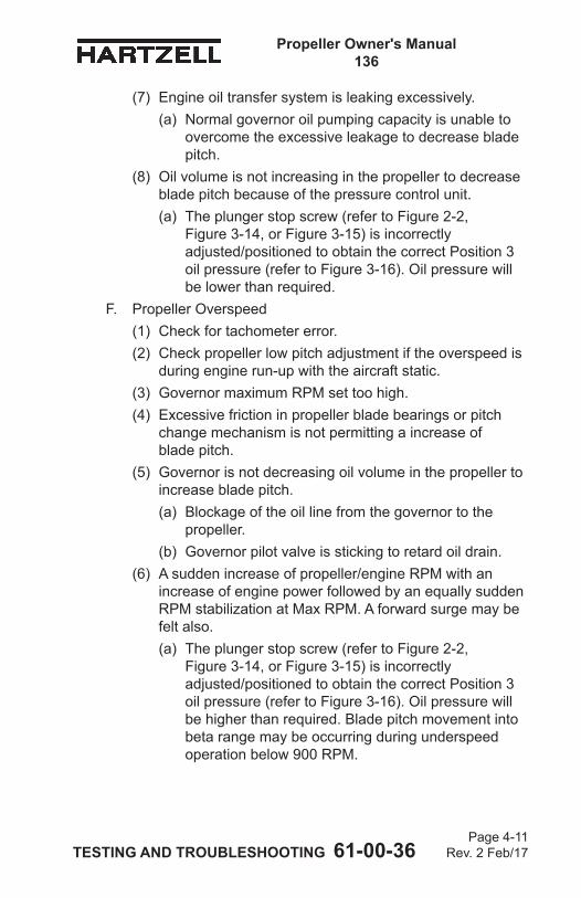
Propeller Owner's Manual 136
TESTING AND TROUBLESHOOTING 61-00-36 Page 4-11
Rev. 2 Feb/17
(7) Engine oil transfer system is leaking excessively. (a) Normal governor oil pumping capacity is unable to
overcome the excessive leakage to decrease blade pitch.
(8) Oil volume is not increasing in the propeller to decrease blade pitch because of the pressure control unit.(a) The plunger stop screw (refer to Figure 2-2,
Figure 3-14, or Figure 3-15) is incorrectly adjusted/positioned to obtain the correct Position 3 oil pressure (refer to Figure 3-16). Oil pressure will be lower than required.
F. Propeller Overspeed(1) Check for tachometer error.(2) Check propeller low pitch adjustment if the overspeed is
during engine run-up with the aircraft static.(3) Governor maximum RPM set too high.(4) Excessive friction in propeller blade bearings or pitch
change mechanism is not permitting a increase of blade pitch.
(5) Governor is not decreasing oil volume in the propeller to increase blade pitch.(a) Blockage of the oil line from the governor to the
propeller.(b) Governor pilot valve is sticking to retard oil drain.
(6) A sudden increase of propeller/engine RPM with an increase of engine power followed by an equally sudden RPM stabilization at Max RPM. A forward surge may be felt also.(a) The plunger stop screw (refer to Figure 2-2,
Figure 3-14, or Figure 3-15) is incorrectly adjusted/positioned to obtain the correct Position 3 oil pressure (refer to Figure 3-16). Oil pressure will be higher than required. Blade pitch movement into beta range may be occurring during underspeed operation below 900 RPM.
Propeller Owner's Manual 136
TESTING AND TROUBLESHOOTING 61-00-36 Page 4-12
Rev. 2 Feb/17
G. Beta Range Operation(1) Propeller refuses to enter beta range from low pitch
blade angle.(a) Propeller RPM is not below 900 RPM.
1 Beta lockout flyweights in the beta lockout assembly prevent movement into the beta range unless the engine/propeller speed is below 900 RPM.
2 Beta lockout flyweights will not disengage from a groove in the barrel (inside diameter) because of damage. Propeller must disassembled and repaired by qualified personnel at a certified propeller repair station with the appropriate rating.
(b) Low oil pressure. Oil pressure supplied to the propeller by the pressure control unit when commanded by the pilot control is less that required to move blade angle from low pitch into beta range.1 Check the output oil pressure increase on the
oil pressure gauge that is connected to the pressure control unit. Refer to Figure 2-2.
2 Oil pressure increase from the Position 3 oil pressure valve at low pitch (refer to Figure 3-16) should be a minimum of 75 PSI to easily enter beta range.
3 Pressure relief compression spring in the pressure control unit may be broken. Refer to Figure 2-2.
4 Relief valve may be jammed or broken. Refer to Figure 2-2.
(c) Mechanical connection between the pilot control to the pressure control unit is either jammed or disconnected.
Propeller Owner's Manual 136
TESTING AND TROUBLESHOOTING 61-00-36 Page 4-13
Rev. 2 Feb/17
H. Vibration
CAUTION 1: ANY VIBRATION THAT OCCURS SUDDENLY, OR THAT IS ACCOMPANIED BY UNEXPLAINED GREASE LEAKAGE SHOULD BE INVESTIGATED IMMEDIATELY BEFORE FURTHER FLIGHT.
CAUTION 2: VIBRATION PROBLEMS BECAUSE OF PROPELLER SYSTEM IMBALANCE ARE NORMALLY FELT THROUGHOUT THE RPM RANGE, WITH THE INTENSITY OF VIBRATION INCREASING WITH RPM. VIBRATION PROBLEMS THAT OCCUR IN A NARROW RPM RANGE ARE A SYMPTOM OF RESONANCE, THAT IS POTENTIALLY HARMFUL TO THE PROPELLER. AVOID OPERATION UNTIL THE PROPELLER CAN BE CHECKED AT A CERTIFIED PROPELLER REPAIR STATION WITH THE APPROPRIATE RATING.
(1) Check:(a) Control surfaces, cowl flaps, exhaust system,
landing gear doors, etc. for excessive play, which may be causing vibration unrelated to the propeller.
(b) Secure attachment of engine mounted hardware.(c) Engine mount wear.(d) Uneven or over lubrication of propeller.(e) Correct engine/propeller flange mating. (f) Blade track. Refer to Blade Track in the Inspection
and Check chapter of this manual.(g) Blade angles: Blade angle must be within 0.2 degree
from blade to blade.(h) Spinner for cracks, incorrect installation, or "wobble"
during operation.(i) Static balance.
Propeller Owner's Manual 136
TESTING AND TROUBLESHOOTING 61-00-36 Page 4-14
Rev. 2 Feb/17
(j) Airfoil profile identical between blades. After overhaul or repair for nicks - verify at a certified propeller repair station with the appropriate rating.
(k) Hub or blade damage or cracking.(l) Grease or oil leakage.(m) Bends or blade deformation.
NOTE: Dynamic balancing is recommended after installing or performing maintenance on a propeller. While normally an optional task, it may be required by the engine or airframe manufacturer to make certain the propeller/engine combination is balanced correctly before operation. Refer to the engine or airframe manuals, and the Maintenance Practices chapter of this manual.
Propeller Owner's Manual 136
TESTING AND TROUBLESHOOTING 61-00-36 Page 4-15
Rev. 2 Feb/17
I. Oil or Grease LeakageNOTE: A new propeller may leak grease slightly during
the first several hours of operation. This leakage may be caused by the seating of seals and O-rings, and the slinging of lubricants used during assembly. Such leakage should stop within the first ten hours of operation.
CAUTION: GREASE LEAKAGE THAT CAN BE DESCRIBED AS EXCESSIVE AND APPEARING SUDDENLY, ESPECIALLY WHEN ACCOMPANIED BY VIBRATION SHOULD BE INVESTIGATED IMMEDIATELY BEFORE FURTHER FLIGHT.
(1) Check:(a) Improperly torqued or loose lubrication fitting(b) Defective lubrication fitting(c) Damaged blade shank to hub O-ring seal(d) Damaged hub seal (at hub parting line)(e) Damaged O-ring at hub/engine flange interface(f) Cracked hub.
1 A cracked hub is often indicated by grease emerging from a seemingly solid surface, especially in the blade arm area

Propeller Owner's Manual 136
TESTING AND TROUBLESHOOTING 61-00-36 Page 4-16
Rev. 2 Feb/17
(This page is intentionally blank.)
Propeller Owner’s Manual 136
INSPECTION AND CHECK 61-00-36 Page 5-1
Rev. 2 Feb/17
INSPECTION AND CHECK - CONTENTS
1. Pre-Flight Checks .................................................................... 5-3
2. Operational Checks ................................................................. 5-5
3. Required Periodic Inspections and Maintenance ..................... 5-7A. Periodic Inspections .......................................................... 5-7B. Periodic Maintenance ........................................................ 5-8C. Airworthiness Limitations ................................................... 5-9D. Overhaul Periods ............................................................. 5-10
4. Inspection Procedures ............................................................5-11A. Blade Damage ..................................................................5-11B. Grease or Oil Leakage .................................................... 5-12C. Vibration .......................................................................... 5-14D. Blade Track ...................................................................... 5-17E. Loose Blades ................................................................... 5-18F. Corrosion ......................................................................... 5-18G. Spinner Damage .............................................................. 5-19H. Electric De-ice System .................................................... 5-19I. Anti-ice System ................................................................ 5-19
5. Special Inspections ................................................................ 5-21A. Overspeed ....................................................................... 5-21B. Lightning Strike ................................................................ 5-22C. Foreign Object Strike ....................................................... 5-23D. Fire Damage or Heat Damage ........................................ 5-25
6. Long Term Storage................................................................. 5-26
Propeller Owner’s Manual 136
INSPECTION AND CHECK 61-00-36 Page 5-2
Rev. 2 Feb/17
LIST OF FIGURES
Checking Blade Track.................................. Figure 5-1 ............... 5-16
Blade Play ................................................... Figure 5-2 ................ 5-16
Reciprocating Engine Overspeed Limits ..... Figure 5-3 ................ 5-20
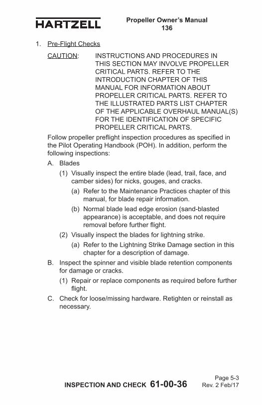
Propeller Owner’s Manual 136
INSPECTION AND CHECK 61-00-36 Page 5-3
Rev. 2 Feb/17
1. Pre-Flight Checks
CAUTION: INSTRUCTIONS AND PROCEDURES IN THIS SECTION MAY INVOLVE PROPELLER CRITICAL PARTS. REFER TO THE INTRODUCTION CHAPTER OF THIS MANUAL FOR INFORMATION ABOUT PROPELLER CRITICAL PARTS. REFER TO THE ILLUSTRATED PARTS LIST CHAPTER OF THE APPLICABLE OVERHAUL MANUAL(S) FOR THE IDENTIFICATION OF SPECIFIC PROPELLER CRITICAL PARTS.
Follow propeller preflight inspection procedures as specified in the Pilot Operating Handbook (POH). In addition, perform the following inspections:A. Blades
(1) Visually inspect the entire blade (lead, trail, face, and camber sides) for nicks, gouges, and cracks. (a) Refer to the Maintenance Practices chapter of this
manual, for blade repair information. (b) Normal blade lead edge erosion (sand-blasted
appearance) is acceptable, and does not require removal before further flight.
(2) Visually inspect the blades for lightning strike. (a) Refer to the Lightning Strike Damage section in this
chapter for a description of damage.B. Inspect the spinner and visible blade retention components
for damage or cracks. (1) Repair or replace components as required before further
flight.C. Check for loose/missing hardware. Retighten or reinstall as
necessary.
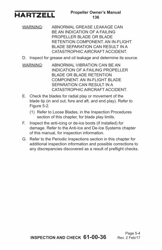
Propeller Owner’s Manual 136
INSPECTION AND CHECK 61-00-36 Page 5-4
Rev. 2 Feb/17
WARNING: ABNORMAL GREASE LEAKAGE CAN BE AN INDICATION OF A FAILING PROPELLER BLADE OR BLADE RETENTION COMPONENT. AN IN-FLIGHT BLADE SEPARATION CAN RESULT IN A CATASTROPHIC AIRCRAFT ACCIDENT.
D. Inspect for grease and oil leakage and determine its source.
WARNING: ABNORMAL VIBRATION CAN BE AN INDICATION OF A FAILING PROPELLER BLADE OR BLADE RETENTION COMPONENT. AN IN-FLIGHT BLADE SEPARATION CAN RESULT IN A CATASTROPHIC AIRCRAFT ACCIDENT.
E. Check the blades for radial play or movement of the blade tip (in and out, fore and aft, and end play). Refer to Figure 5-2.(1) Refer to Loose Blades, in the Inspection Procedures
section of this chapter, for blade play limits. F. Inspect the anti-icing or de-ice boots (if installed) for
damage. Refer to the Anti-Ice and De-Ice Systems chapter of this manual, for inspection information.
G. Refer to the Periodic Inspections section in this chapter for additional inspection information and possible corrections to any discrepancies discovered as a result of preflight checks.
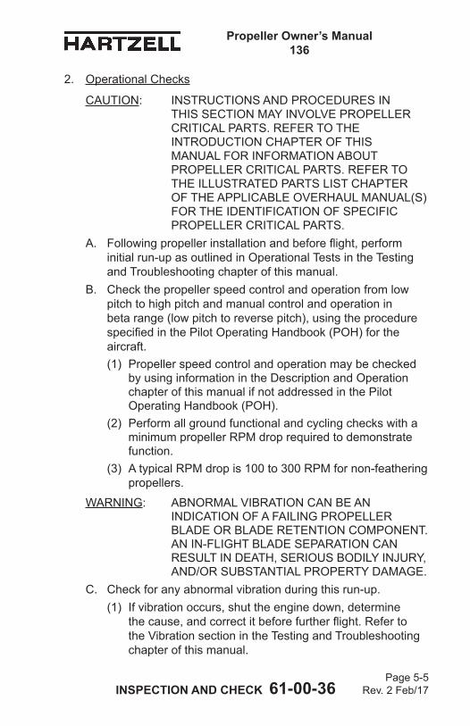
Propeller Owner’s Manual 136
INSPECTION AND CHECK 61-00-36 Page 5-5
Rev. 2 Feb/17
2. Operational Checks
CAUTION: INSTRUCTIONS AND PROCEDURES IN THIS SECTION MAY INVOLVE PROPELLER CRITICAL PARTS. REFER TO THE INTRODUCTION CHAPTER OF THIS MANUAL FOR INFORMATION ABOUT PROPELLER CRITICAL PARTS. REFER TO THE ILLUSTRATED PARTS LIST CHAPTER OF THE APPLICABLE OVERHAUL MANUAL(S) FOR THE IDENTIFICATION OF SPECIFIC PROPELLER CRITICAL PARTS.
A. Following propeller installation and before flight, perform initial run-up as outlined in Operational Tests in the Testing and Troubleshooting chapter of this manual.
B. Check the propeller speed control and operation from low pitch to high pitch and manual control and operation in beta range (low pitch to reverse pitch), using the procedure specified in the Pilot Operating Handbook (POH) for the aircraft.(1) Propeller speed control and operation may be checked
by using information in the Description and Operation chapter of this manual if not addressed in the Pilot Operating Handbook (POH).
(2) Perform all ground functional and cycling checks with a minimum propeller RPM drop required to demonstrate function.
(3) A typical RPM drop is 100 to 300 RPM for non-feathering propellers.
WARNING: ABNORMAL VIBRATION CAN BE AN INDICATION OF A FAILING PROPELLER BLADE OR BLADE RETENTION COMPONENT. AN IN-FLIGHT BLADE SEPARATION CAN RESULT IN DEATH, SERIOUS BODILY INJURY, AND/OR SUBSTANTIAL PROPERTY DAMAGE.
C. Check for any abnormal vibration during this run-up. (1) If vibration occurs, shut the engine down, determine
the cause, and correct it before further flight. Refer to the Vibration section in the Testing and Troubleshooting chapter of this manual.
Propeller Owner’s Manual 136
INSPECTION AND CHECK 61-00-36 Page 5-6
Rev. 2 Feb/17
D. Refer to Periodic Inspections in this chapter for additional inspection information and possible corrections to any discrepancies discovered as a result of Pre-Flight Checks.
E. Refer to the airframe manufacturer’s manual for additional operational checks.
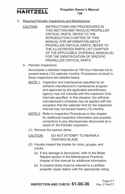
Propeller Owner’s Manual 136
INSPECTION AND CHECK 61-00-36 Page 5-7
Rev. 2 Feb/17
3. Required Periodic Inspections and Maintenance
CAUTION: INSTRUCTIONS AND PROCEDURES IN THIS SECTION MAY INVOLVE PROPELLER CRITICAL PARTS. REFER TO THE INTRODUCTION CHAPTER OF THIS MANUAL FOR INFORMATION ABOUT PROPELLER CRITICAL PARTS. REFER TO THE ILLUSTRATED PARTS LIST CHAPTER OF THE APPLICABLE OVERHAUL MANUAL(S) FOR THE IDENTIFICATION OF SPECIFIC PROPELLER CRITICAL PARTS.
A. Periodic InspectionsAccomplish a detailed inspection at 100 hour intervals not to exceed twelve (12) calendar months. Procedures involved in these inspections are detailed below.NOTE 1: Inspection and maintenance specified by an
airframe manufacturer's maintenance program and approved by the applicable airworthiness agency may not coincide with the inspection time intervals specified. In this situation, the airframe manufacturer's schedule may be applied with the exception that the calendar limit for the inspection interval may not exceed twelve (12) months.
NOTE 2: Refer to Inspection Procedures in this chapter for additional inspection information and possible corrections to any discrepancies discovered as a result of the Periodic Inspection.
(1) Remove the spinner dome.
CAUTION: DO NOT ATTEMPT TO REPAIR A CRACKED BLADE.
(2) Visually inspect the blades for nicks, gouges, and cracks. (a) If any damage is discovered, refer to the Blade
Repairs section in the Maintenance Practices chapter of this manual for additional information.
(b) A cracked blade must be referred to a certified propeller repair station with the appropriate rating.
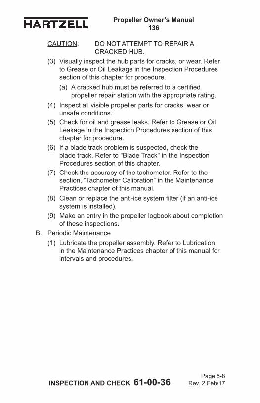
Propeller Owner’s Manual 136
INSPECTION AND CHECK 61-00-36 Page 5-8
Rev. 2 Feb/17
CAUTION: DO NOT ATTEMPT TO REPAIR A CRACKED HUB.
(3) Visually inspect the hub parts for cracks, or wear. Refer to Grease or Oil Leakage in the Inspection Procedures section of this chapter for procedure. (a) A cracked hub must be referred to a certified
propeller repair station with the appropriate rating. (4) Inspect all visible propeller parts for cracks, wear or
unsafe conditions.(5) Check for oil and grease leaks. Refer to Grease or Oil
Leakage in the Inspection Procedures section of this chapter for procedure.
(6) If a blade track problem is suspected, check the blade track. Refer to "Blade Track" in the Inspection Procedures section of this chapter.
(7) Check the accuracy of the tachometer. Refer to the section, “Tachometer Calibration” in the Maintenance Practices chapter of this manual.
(8) Clean or replace the anti-ice system filter (if an anti-ice system is installed).
(9) Make an entry in the propeller logbook about completion of these inspections.
B. Periodic Maintenance(1) Lubricate the propeller assembly. Refer to Lubrication
in the Maintenance Practices chapter of this manual for intervals and procedures.
Propeller Owner’s Manual 136
INSPECTION AND CHECK 61-00-36 Page 5-9
Rev. 2 Feb/17
C. Airworthiness Limitations(1) Certain components, as well as the entire propeller
may have specific life limits established as part of the certification by the FAA. Such limits require mandatory replacement of specified parts after a defined number of hours and/or cycles of use.
(2) Life limited component times may exist for the propeller models included in this manual. Refer to the Airworthiness Limitations chapter of this manual.
(3) Operators are urged to keep informed of airworthiness information via Hartzell Propeller Inc. Service Bulletins and Service Letters, which are available from Hartzell Propeller Inc. distributors or from the Hartzell Propeller Inc. factory by subscription. Selected information is also available on the Hartzell Propeller Inc. website at www.hartzellprop.com.
Propeller Owner’s Manual 136
INSPECTION AND CHECK 61-00-36 Page 5-10
Rev. 2 Feb/17
D. Overhaul PeriodsIn flight, the propeller is constantly subjected to vibration from the engine and the airstream, as well as high centrifugal forces. The propeller is also subject to corrosion, wear, and general deterioration due to aging. Under these conditions, metal fatigue or mechanical failures can occur. In order to protect your safety, your investment, and to maximize the safe operating lifetime of your propeller, it is essential that a propeller be properly maintained and overhauled according to the recommended service procedures.
CAUTION 1: OVERHAUL PERIODS LISTED BELOW, ALTHOUGH CURRENT AT THE TIME OF PUBLICATION, ARE FOR REFERENCE PURPOSES ONLY. OVERHAUL PERIODS MAY BE INCREASED OR DECREASED AS A RESULT OF EVALUATION.
CAUTION 2: REFER TO THE LATEST REVISION OF HARTZELL PROPELLER INC. SERVICE LETTER HC-SL-61-61Y FOR THE MOST CURRENT INFORMATION. THE SERVICE LETTER IS AVAILABLE ON THE HARTZELL PROPELLER INC. WEBSITE AT WWW.HARTZELLPROP.COM.
(1) Reciprocating Engine Installations(a) Three blade propellers manufactured before 1983
are to be overhauled at 2000 hours. See paragraph 3.D.(1)(c) for calendar limits.
(b) Three blade propellers manufactured after 1983 are to be overhauled at 2400 hours. See paragraph 3.D.(1)(c) for calendar limits.
(c) Propellers manufactured or overhauled since October 1991 are required to have the internal hub surface painted for additional corrosion protection. Hubs with painted internal surface have a 72 month overhaul calendar limit. Hubs which have not had the internal surface painted have a 60 month overhaul calendar limit until the hub internal surface is painted for corrosion protection. After painting, calendar limit increases to 72 months.
Propeller Owner’s Manual 136
INSPECTION AND CHECK 61-00-36 Page 5-11
Rev. 2 Feb/17
4. Inspection Procedures
CAUTION: INSTRUCTIONS AND PROCEDURES IN THIS SECTION MAY INVOLVE PROPELLER CRITICAL PARTS. REFER TO THE INTRODUCTION CHAPTER OF THIS MANUAL FOR INFORMATION ABOUT PROPELLER CRITICAL PARTS. REFER TO THE ILLUSTRATED PARTS LIST CHAPTER OF THE APPLICABLE OVERHAUL MANUAL(S) FOR THE IDENTIFICATION OF SPECIFIC PROPELLER CRITICAL PARTS.
The following inspections must be made on a regular basis, either before flight, during required periodic inspection, as described in this chapter, or if a problem is noted. Possible corrections to problems discovered during inspections, additional inspections, and limits are detailed in the following inspection procedures.A. Blade Damage
(1) Refer to Blade Repairs section in the Maintenance Practices chapter of this manual for information regarding blade damage.
Propeller Owner’s Manual 136
INSPECTION AND CHECK 61-00-36 Page 5-12
Rev. 2 Feb/17
B. Grease or Oil Leakage
WARNING: UNUSUAL OR ABNORMAL GREASE LEAKAGE OR VIBRATION, WHERE THE CONDITION STARTED SUDDENLY, CAN BE AN INDICATION OF A FAILING PROPELLER BLADE OR BLADE RETENTION COMPONENT. AN INFLIGHT BLADE SEPARATION CAN RESULT IN DEATH, SERIOUS BODILY INJURY, AND/OR SUBSTANTIAL PROPERTY DAMAGE. UNUSUAL OR ABNORMAL GREASE LEAKAGE OR VIBRATION DEMANDS IMMEDIATE INSPECTION FOR A POSSIBLE CRACKED HUB.
NOTE: A new or newly overhauled propeller may leak slightly during the first several hours of operation. This leakage may be caused by the seating of seals and O-rings, and the slinging of lubricants used for seal lubrication during assembly. Such leakage should cease within the first ten hours of operation.
(1) Leakage that persists beyond the first ten hours of operation ona new or newly overhauled propeller, or occurs on a propeller that has been in service for some time will require repair. A determination should be made as to the source of the leak. The only leakage that is field repairable is the removal and replacement of the O-ring seal between the engine and propeller flange. All other leakage repairs should be referred to a certified propeller repair station with the appropriate rating. An instance of abnormal grease leakage should be inspected using the following the procedure:(a) Remove the spinner dome.
Propeller Owner’s Manual 136
INSPECTION AND CHECK 61-00-36 Page 5-13
Rev. 2 Feb/17
CAUTION: PERFORM A VISUAL INSPECTION WITHOUT CLEANING THE PARTS. A TIGHT CRACK IS OFTEN EVIDENT DUE TO TRACES OF GREASE EMANATING FROM THE CRACK. CLEANING CAN REMOVE SUCH EVIDENCE AND MAKE A CRACK VIRTUALLY IMPOSSIBLE TO SEE.
(b) Perform a visual inspection for cracks in the hub. 1 A crack may be readily visible, or may be indicated
by grease leaking from a seemingly solid surface. Extra attention should be given to the blade retention area of the hub.
(c) Perform a visual inspection of the hub and blade retention areas to locate the origin of leakage. 1 If the origin of grease leakage is determined to be a
noncritical part such as an O-ring or sealant, repairs can be accomplished during scheduled maintenance, as long as flight safety is not compromised.
(d) If cracks are suspected, additional inspections must be performed before further flight. 1 These inspections must be
performed by qualified personnel at a certified propeller repair station with the appropriate rating to verify the condition. Such inspections typically include disassembly of the propeller followed by inspection of parts, using nondestructive methods in accordance with published procedures.
(e) If cracks or failing components are found, parts must be replaced before further flight. 1 Report such incidents to the appropriate
airworthiness authorities and Hartzell Propeller Inc. Product Support.
Propeller Owner’s Manual 136
INSPECTION AND CHECK 61-00-36 Page 5-14
Rev. 2 Feb/17
C. VibrationInstances of abnormal vibration should be investigated immediately. If the cause of the vibration is not readily apparent, the propeller may be inspected following the procedure below:NOTE: It may be difficult to readily identify the cause of
abnormal vibration. It may originate in the engine, propeller, or airframe. Troubleshooting procedures typically initiate with investigation of the engine. Airframe components (such as engine mounts or loose landing gear doors) can also be the source of vibration. When investigating an abnormal vibration, the possibility of a failing blade or blade retention component should be considered as a potential source of the problem.
(1) Perform troubleshooting and evaluation of possible sources of vibration in accordance with engine or airframe manufacturer's instructions.
(2) Refer to the Vibration section in the Testing and Troubleshooting chapter of this manual. Perform the checks to determine possible cause of the vibration. (a) If no cause is found, then consider that the origin of
the problem could be the propeller and proceed with steps 4.C.(3) through 4.C.(8) in this chapter.
(3) Remove the spinner dome.(4) Perform a visual inspection for cracks in the hub.
(a) Pay particular attention to the blade retention areas of the hub.
(b) A crack may be readily visible or may be indicated by grease leaking from a seemingly solid surface.
(5) If cracks are suspected, additional inspections must be performed before further flight. These inspections must be performed by qualified personnel at a certified propeller repair station with the appropriate rating to verify the condition. Such inspections typically include disassembly of the propeller, followed by inspection of parts, using nondestructive methods in accordance with published procedures.
Propeller Owner’s Manual 136
INSPECTION AND CHECK 61-00-36 Page 5-15
Rev. 2 Feb/17
(6) Examine the blades and compare blade-to-blade differences:(a) Inspect the propeller blades for unusual looseness or
movement. Refer to the section "Loose Blades" in this chapter.
(b) Examine blade track. Refer to the section "Blade Track" in this chapter.
CAUTION: DO NOT USE BLADE PADDLES TO TURN THE BLADES.
(c) Manually (by hand) attempt to turn the blades (change pitch).
(d) Visually check for damaged blades.(7) If abnormal blade conditions or damage are found,
perform additional inspections by qualified personnel at a certified propeller repair station with the appropriate rating to evaluate the condition. Refer to the Blade Repairs section in the Maintenance Practices chapter of this manual.
(8) If cracks or failing components are found, these parts must be replaced before further flight. (a) Report such incidents to airworthiness authorities and
Hartzell Propeller Inc. Product Support.
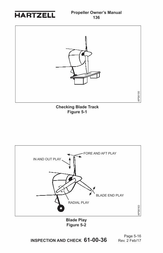
Propeller Owner’s Manual 136
INSPECTION AND CHECK 61-00-36 Page 5-16
Rev. 2 Feb/17
AP
S61
55
Checking Blade Track Figure 5-1
Blade Play Figure 5-2
AP
S61
63
BLADE END PLAY
IN AND OUT PLAY
RADIAL PLAY
FORE AND AFT PLAY
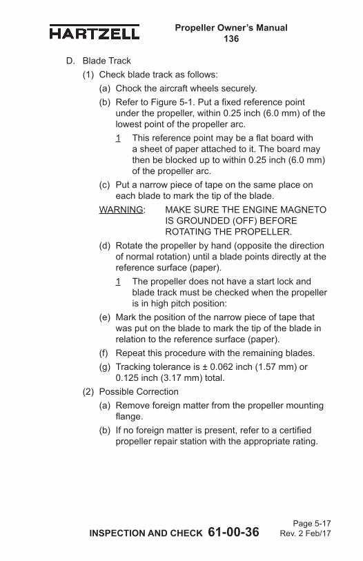
Propeller Owner’s Manual 136
INSPECTION AND CHECK 61-00-36 Page 5-17
Rev. 2 Feb/17
D. Blade Track(1) Check blade track as follows:
(a) Chock the aircraft wheels securely.(b) Refer to Figure 5-1. Put a fixed reference point
under the propeller, within 0.25 inch (6.0 mm) of the lowest point of the propeller arc. 1 This reference point may be a flat board with
a sheet of paper attached to it. The board may then be blocked up to within 0.25 inch (6.0 mm) of the propeller arc.
(c) Put a narrow piece of tape on the same place on each blade to mark the tip of the blade.
WARNING: MAKE SURE THE ENGINE MAGNETO IS GROUNDED (OFF) BEFORE ROTATING THE PROPELLER.
(d) Rotate the propeller by hand (opposite the direction of normal rotation) until a blade points directly at the reference surface (paper). 1 The propeller does not have a start lock and
blade track must be checked when the propeller is in high pitch position:
(e) Mark the position of the narrow piece of tape that was put on the blade to mark the tip of the blade in relation to the reference surface (paper).
(f) Repeat this procedure with the remaining blades.(g) Tracking tolerance is ± 0.062 inch (1.57 mm) or
0.125 inch (3.17 mm) total.(2) Possible Correction
(a) Remove foreign matter from the propeller mounting flange.
(b) If no foreign matter is present, refer to a certified propeller repair station with the appropriate rating.
Propeller Owner’s Manual 136
INSPECTION AND CHECK 61-00-36 Page 5-18
Rev. 2 Feb/17
E. Loose BladesRefer to Figure 5-2. Limits for blade looseness are as follows:End Play (leading edge to trailing edge) See Note below Fore & Aft Movement (Face to camber) See Note below In & Out None Radial Play (pitch change) ± 0.5 degree (1 degree total) measured at reference stationNOTE: Blades are intended to be tight in the propeller,
however slight movement is acceptable if the blade returns to its original position when released. Blades with excessive movement, or that do not return to their original position when released may indicate internal wear or damage which should be referred to a certified propeller repair station with the appropriate rating.
F. Corrosion
WARNING: REWORK THAT INVOLVES COLD WORKING THE METAL, RESULTING IN CONCEALMENT OF A DAMAGED AREA IS NOT PERMITTED.
(1) Light corrosion on the blades may be removed by qualified personnel in accordance with the Blade Repairs section in the Maintenance Practices chapter of this manual.
(2) Heavy corrosion that results in severe pitting must be referred to a certified propeller repair station with the appropriate rating.
Propeller Owner’s Manual 136
INSPECTION AND CHECK 61-00-36 Page 5-19
Rev. 2 Feb/17
G. Spinner Damage(1) Examine the spinner for cracks, missing hardware, or
other damage. (a) For metal spinners, refer to Hartzell Propeller Inc.
Metal Spinner Maintenance Manual 127 (61-16-27) or a certified propeller repair station with the appropriate rating for spinner damage acceptance and repair information. Contact the local airworthiness authority for repair approval.
(b) For composite spinners, refer to Hartzell Propeller Inc. Composite Spinner Maintenance Manual 173 (61-16-73) or a certified propeller repair station with the appropriate rating for spinner damage acceptance and repair information. Contact the local airworthiness authority for repair approval.
H. Electric De-ice System(1) Refer to the Anti-ice and De-ice Systems chapter of this
manual for inspection procedures.I. Anti-ice System
(1) Refer to the Anti-ice and De-ice Systems chapter of this manual for inspection procedures.
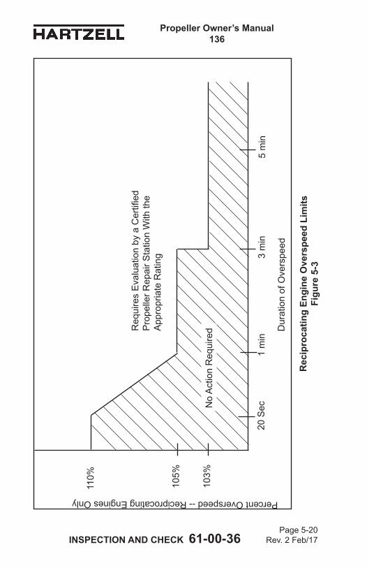
Propeller Owner’s Manual 136
INSPECTION AND CHECK 61-00-36 Page 5-20
Rev. 2 Feb/17
Percent Overspeed -- Reciprocating Engines Only
Rec
ipro
catin
g En
gine
Ove
rspe
ed L
imits
Fi
gure
5-3
Dur
atio
n of
Ove
rspe
ed
105%
20 S
ec1
min
3 m
in5
min
110%
103%
Req
uire
s E
valu
atio
n by
a C
ertifi
ed
Pro
pelle
r Rep
air S
tatio
n W
ith th
e A
ppro
pria
te R
atin
g
No
Act
ion
Req
uire
d
Propeller Owner’s Manual 136
INSPECTION AND CHECK 61-00-36 Page 5-21
Rev. 2 Feb/17
5. Special Inspections
CAUTION: INSTRUCTIONS AND PROCEDURES IN THIS SECTION MAY INVOLVE PROPELLER CRITICAL PARTS. REFER TO THE INTRODUCTION CHAPTER OF THIS MANUAL FOR INFORMATION ABOUT PROPELLER CRITICAL PARTS. REFER TO THE ILLUSTRATED PARTS LIST CHAPTER OF THE APPLICABLE OVERHAUL MANUAL(S) FOR THE IDENTIFICATION OF SPECIFIC PROPELLER CRITICAL PARTS.
A. OverspeedAn overspeed occurrs when the propeller RPM exceeds the maximum RPM stated in the applicable Aircraft Type Certificate Data Sheet. An overspeed condition occurs when the engine speed exceeds the limits established by the engine, propeller, or airframe manufacturer. The duration of time at overspeed for a single event determines the corrective action that must be taken to make sure no damage to the propeller has occurred.The criteria for determining the required action after an overspeed are based on many factors. The additional centrifugal forces that occur during overspeed are not the only concern. Some applications have sharp increases in vibratory stresses at RPMs above the maximum rated for the airframe/engine/propeller combination.(1) When a propeller installed on a reciprocating engine has
an overspeed event, refer to the Reciprocating Engine Overspeed Limits (Figure 5-3) to determine the corrective action to be taken.
(2) Make an entry in the propeller logbook about the overspeed event.
Propeller Owner’s Manual 136
INSPECTION AND CHECK 61-00-36 Page 5-22
Rev. 2 Feb/17
B. Lightning Strike
CAUTION: ALSO CONSULT ENGINE AND AIRFRAME MANUFACTURER'S MANUALS. THERE MAY BE ADDITIONAL REQUIREMENTS SUCH AS DE-ICE AND ENGINE SYSTEM CHECKS TO PERFORM AFTER A PROPELLER LIGHTNING STRIKE.
(1) General(a) In the event of a propeller lightning strike, an inspection
is required before further flight. It may be permissible for a propeller to be operated for an additional ten (10) hours if the propeller is not severely damaged and meets the requirements in paragraph 5.B.(2).
(b) Regardless of the outcome of the initial inspection, the propeller must be removed from the aircraft, disassembled, evaluated, and/or repaired by a certified propeller repair station with the appropriate rating.
(2) Procedure for Temporary OperationIf temporary additional operation is desired before propeller removal and disassembly:(a) Remove spinner dome and perform visual inspection
of propeller, spinner, and de-ice system for evidence of significant damage that would require repair before flight (such as broken de-ice wires or arcing damage to propeller hub).
CAUTION: IF THE PROPELLER EXPERIENCES A LIGHTNING STRIKE,THE ALUMINUM BLADES MUST BE WITHIN AIRWORTHY LIMITS FOR ANY ADDITIONAL FLIGHT.
(b) If the only evident damage is slight arcing burns to the blades, then operation for ten (10) hours is acceptable before disassembly and inspection.
(c) Perform a functional check of the propeller de-ice system (if installed) in accordance with aircraft maintenance manual procedures.
Propeller Owner’s Manual 136
INSPECTION AND CHECK 61-00-36 Page 5-23
Rev. 2 Feb/17
(d) Regardless of the degree of damage, make an entry in the propeller logbook about the lightning strike.
(e) The propeller must be removed from the aircraft, disassembled, evaluated, and/or repaired by a certified propeller repair station with the appropriate rating for flight beyond the temporary operation limits granted above.
C. Foreign Object Strike(1) General
(a) A foreign object strike can include a broad spectrum of damage, from a minor stone nick to severe ground impact damage. A conservative approach in evaluating the damage is required because there may be hidden damage that is not readily apparent during an on-wing, visual inspection.
(b) A foreign object strike is defined as:1 Any incident, whether or not the engine is
operating, that requires repair to the propeller other than minor dressing of the blades. Examples of foreign object strike include situations where an aircraft is stationary and the landing gear collapses causing one or more blades to be significantly damaged, or where a hangar door (or other object) strikes the propeller blade. These cases should be handled as foreign object strikes because of potentially severe side loading on the propeller hub, blades and retention bearings.
2 Any incident during engine operation in which the propeller impacts a solid object that causes a drop in revolutions per minute (RPM) and also requires structural repair of the propeller (incidents requiring only paint touch-up are not included). This is not restricted to propeller strikes against the ground.
3 A sudden RPM drop while impacting water, tall grass, or similar yielding medium, where propeller blade damage is not normally incurred.
Propeller Owner’s Manual 136
INSPECTION AND CHECK 61-00-36 Page 5-24
Rev. 2 Feb/17
(2) Procedure(a) In the event of a foreign object strike, an inspection is
required before further flight. If the inspection reveals one or more of the following indications, the propeller must be removed from the aircraft, disassembled and overhauled in accordance with the applicable propeller and blade maintenance manuals.1 A loose blade in the hub.2 Any noticeable or suspected damage to the pitch
change mechanism. 3 A bent blade (out of track or angle).4 Any blade diameter reduction.5 A bent, cracked, or failed engine shaft.6 Vibration during operation that was not present
before the event.(b) Nicks, gouges, and scratches on blade surfaces
or the leading and trailing edges must be removed before flight. Refer to the Blade Repairs section in the Maintenance Practices chapter of this manual.
(c) For engine mounted accessories - for example, governors, pumps, and propeller control units manufactured by Hartzell Propeller Inc. - if the foreign object strike resulted in a sudden stop of the engine, the unit must be disassembled and inspected in accordance with the applicable maintenance manual.
(d) Regardless of the degree of damage, make a log book entry to document the foreign object strike incident and any corrective action(s) taken.
Propeller Owner’s Manual 136
INSPECTION AND CHECK 61-00-36 Page 5-25
Rev. 2 Feb/17
D. Fire Damage or Heat Damage
WARNING: HUBS ARE MANUFACTURED FROM HEAT TREATED FORGINGS AND ARE SHOT PEENED. BLADES ARE MANUFACTURED FROM HEAT TREATED FORGINGS AND ARE COMPRESSIVELY ROLLED AND SOMETIMES SHOT PEENED. EXPOSURE TO HIGH TEMPERATURES CAN DESTROY THE FATIGUE BENEFITS OBTAINED FROM THESE PROCESSES.
(1) On rare occasions propellers may be exposed to fire or heat damage such as an engine or hangar fire. In the event of such an incident, an inspection by a certified propeller repair station with the appropriate rating is required before further flight.
Propeller Owner’s Manual 136
INSPECTION AND CHECK 61-00-36 Page 5-26
Rev. 2 Feb/17
6. Long Term StorageNOTE: Specific Hartzell Propeller Inc. manuals and service
documents are available on the Hartzell Propeller Inc. website at www.hartzellprop.com. Refer to the Required Publications section in the Introduction chapter of this manual for the identification of these publications.
A. Parts shipped from the Hartzell Propeller Inc. factory are not shipped or packaged in a container that is designed for long term storage.
B. Long term storage procedures may be obtained by contacting a Hartzell Propeller Inc. distributor, or the Hartzell Propeller Inc. factory via the Product Support number listed in the Introduction chapter of this manual. Storage information is also detailed in Hartzell Propeller Inc. Standard Practices Manual 202A (61-01-02), Volume 7, Consumable Materials and Packaging and Storage that is on the Hartzell Propeller Inc. website at www.hartzellprop.com.
C. Information about the return of a propeller assembly to service after long term storage may be obtained by contacting a Hartzell Propeller Inc. distributor, or the Hartzell Propeller Inc. factory via the Product Support number listed in the Introduction chapter of this manual. This information is also detailed in Hartzell Propeller Inc. Standard Practices Manual 202A (61-01-02), Volume 7, Consumable Materials and Packaging and Storage that is on the Hartzell Propeller Inc. website at www.hartzellprop.com.
MAINTENANCE PRACTICES 61-00-36 Page 6-1
Rev. 2 Feb/17
Propeller Owner's Manual 136
MAINTENANCE PRACTICES - CONTENTS1. Cleaning ................................................................................... 6-3
A. General Cleaning ............................................................... 6-3B. Spinner Cleaning and Polishing ........................................ 6-4
2. Lubrication ............................................................................... 6-7A. Lubrication Intervals .......................................................... 6-7B. Lubrication Procedure ....................................................... 6-9C. Approved Lubricants ........................................................ 6-12
3. Blade Repairs ........................................................................ 6-13A. Repair of Nicks or Gouges .............................................. 6-15B. Repair of Bent Blades ...................................................... 6-17
4. Painting After Repair .............................................................. 6-19A. General ............................................................................ 6-19B. Painting of Aluminum Blades ........................................... 6-20
5. Dynamic Balance ................................................................... 6-23A. Overview .......................................................................... 6-23B. Inspection Procedures Before Balancing ........................ 6-24C. Modifying Spinner Bulkhead to Accommodate Dynamic Balance Weights ............................................... 6-25D. Placement of Balance Weights for Dynamic Balance ..... 6-26
6. Propeller Low Pitch Setting .................................................... 6-27A. Low Pitch ......................................................................... 6-27
7. Propeller Pitch Settings .......................................................... 6-29A. High Pitch Stop ............................................................... 6-29B. Low Pitch Stop ................................................................ 6-29C. Reverse Pitch Stop ......................................................... 6-29
8. Propeller Ice Protection Systems ........................................... 6-29A. Electric De-ice System .................................................... 6-29B. Anti-ice System ................................................................ 6-29
9. Tachometer Calibration .......................................................... 6-30
MAINTENANCE PRACTICES 61-00-36 Page 6-2
Rev. 2 Feb/17
Propeller Owner's Manual 136
LIST OF FIGURES
LIST OF TABLES
Approved Touch-up Paints .................................. Table 6-1 .........6-18
Lubrication Fitting Location.................................. Figure 6-1 .........6-6Lubrication Fitting ................................................ Figure 6-2 .........6-8Lubrication Label ................................................. Figure 6-3 .......6-10Repair Limitations ................................................ Figure 6-4 .......6-14
MAINTENANCE PRACTICES 61-00-36 Page 6-3
Rev. 2 Feb/17
Propeller Owner's Manual 136
1. Cleaning
CAUTION 1: INSTRUCTIONS AND PROCEDURES IN THIS SECTION MAY INVOLVE PROPELLER CRITICAL PARTS. REFER TO THE INTRODUCTION CHAPTER OF THIS MANUAL FOR INFORMATION ABOUT PROPELLER CRITICAL PARTS. REFER TO THE ILLUSTRATED PARTS LIST CHAPTER OF THE APPLICABLE OVERHAUL MANUAL(S) FOR THE IDENTIFICATION OF SPECIFIC PROPELLER CRITICAL PARTS.
CAUTION 2: DO NOT USE PRESSURE WASHING EQUIPMENT TO CLEAN THE PROPELLER OR CONTROL COMPONENTS. PRESSURE WASHING CAN FORCE WATER AND/OR CLEANING FLUIDS PAST SEALS AND LEAD TO INTERNAL CORROSION OF PROPELLER COMPONENTS.
A. General Cleaning
CAUTION 1: WHEN CLEANING THE PROPELLER, DO NOT PERMIT SOAP OR SOLVENT SOLUTIONS TO RUN OR SPLASH INTO THE HUB AREA.
CAUTION 2: DO NOT CLEAN THE PROPELLER WITH CAUSTIC OR ACIDIC SOAP SOLUTIONS. IRREPARABLE CORROSION OF PROPELLER COMPONENTS MAY OCCUR.
CAUTION 3: DO NOT USE ANY SOLVENT DURING CLEANING THAT COULD SOFTEN OR DESTROY THE BOND BETWEEN CHEMICALLY ATTACHED PARTS.
(1) To remove grease or oil from propeller surfaces, apply Stoddard Solvent or equivalent to a clean cloth and wipe the part clean.
(2) Using a noncorrosive soap solution, wash the propeller.(3) Thoroughly rinse with water.(4) Permit to dry.
MAINTENANCE PRACTICES 61-00-36 Page 6-4
Rev. 2 Feb/17
Propeller Owner's Manual 136
B. Spinner Cleaning and Polishing(1) Clean the spinner using the General Cleaning
procedures in paragraph 1.A. in this chapter.(2) Polish the dome, if necessary, with an automotive-type
aluminum polish.
MAINTENANCE PRACTICES 61-00-36 Page 6-5
Rev. 2 Feb/17
Propeller Owner's Manual 136
(This page is intentionally blank.)
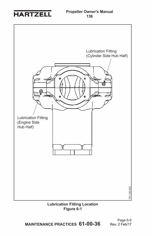
MAINTENANCE PRACTICES 61-00-36 Page 6-6
Rev. 2 Feb/17
Propeller Owner's Manual 136
Lubrication Fitting Location Figure 6-1
Lubrication Fitting (Cylinder Side Hub Half)
Lubrication Fitting (Engine Side Hub Half)
TPI-1
36-0
02
MAINTENANCE PRACTICES 61-00-36 Page 6-7
Rev. 2 Feb/17
Propeller Owner's Manual 136
2. Lubrication
CAUTION: INSTRUCTIONS AND PROCEDURES IN THIS SECTION MAY INVOLVE PROPELLER CRITICAL PARTS. REFER TO THE INTRODUCTION CHAPTER OF THIS MANUAL FOR INFORMATION ABOUT PROPELLER CRITICAL PARTS. REFER TO THE ILLUSTRATED PARTS LIST CHAPTER OF THE APPLICABLE OVERHAUL MANUAL(S) FOR THE IDENTIFICATION OF SPECIFIC PROPELLER CRITICAL PARTS.
A. Lubrication Intervals(1) The propeller must be lubricated at intervals not to
exceed 100 hours or at 12 calendar months, whichever occurs first.(a) If annual operation is significantly less than 100
hours, calendar lubrication intervals should be reduced to six months.
(b) If the aircraft is operated or stored under adverse atmospheric conditions, e.g., high humidity, salt air, calendar lubrication intervals should be reduced to six months.
(2) Owners of high use aircraft may wish to extend their lubrication interval. Lubrication interval may be gradually extended after evaluation of previous propeller overhauls with regard to bearing wear and internal corrosion.
(3) Hartzell Propeller Inc. recommends that new or newly overhauled propellers be lubricated after the first one or two hours of operation because centrifugal loads will pack and redistribute grease, which may result in a propeller imbalance. Redistribution of grease may also result in voids in the blade bearing area where moisture can collect.(a) Purchasers of new aircraft should check the
propeller logbook to verify whether the propeller was lubricated by the manufacturer during flight testing. If it was not lubricated, the propeller should be serviced at the earliest convenience.
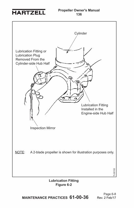
MAINTENANCE PRACTICES 61-00-36 Page 6-8
Rev. 2 Feb/17
Propeller Owner's Manual 136
Lubrication Fitting Figure 6-2
Lubrication Fitting or Lubrication Plug Removed From the Cylinder-side Hub Half
Lubrication Fitting Installed in the Engine-side Hub Half
TI-0
0102
NOTE: A 2-blade propeller is shown for illustration purposes only.
Cylinder
Inspection Mirror
MAINTENANCE PRACTICES 61-00-36 Page 6-9
Rev. 2 Feb/17
Propeller Owner's Manual 136
B. Lubrication Procedure
WARNING 1: FOLLOW LUBRICATION PROCEDURES CORRECTLY TO MAINTAIN AN ACCURATE BALANCE OF THE PROPELLER ASSEMBLY.
WARNING 2: PITCH CONTROL DIFFICULTY COULD RESULT IF THE PROPELLER IS NOT CORRECTLY LUBRICATED.
(1) Remove the propeller spinner dome.(2) Refer to Figure 6-1 and Figure 6-2. Each blade socket has
two lubrication fittings or one lubrication fitting and one lubrication hole plug.
(3) Remove the lubrication fitting caps from the lubrication fittings.
(4) Remove the lubrication fittings or the lubrication hole plugs, as applicable. (a) For all tractor or pusher propellers with clockwise
(standard) rotation when viewed from BEHIND the aircraft, remove the lubrication fittings P/N A-279 or C-6349 or lubrication hole plugs P/N 106545 in the CYLINDER-SIDE hub half.
(b) For all tractor or pusher propellers with counter-clockwise (backward) rotation when viewed from BEHIND the aircraft, remove the lubrication fittings P/N A-279 or C-6349 or lubrication hole plugs P/N 106545 in the ENGINE-SIDE hub half.
(c) Some propellers use an internal blade seal that prevents grease from entering the hub cavity. Because this seal is very efficient, it is important to remove the opposite lubrication fitting. Pitch control difficulty could result if the propeller is not correctly lubricated.
(5) Using a piece of safety wire, loosen any blockage or hardened grease at the threaded holes where the lubrication fitting or lubrication hole plug was removed.
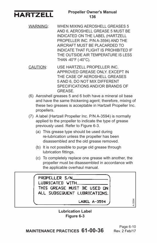
MAINTENANCE PRACTICES 61-00-36 Page 6-10
Rev. 2 Feb/17
Propeller Owner's Manual 136
WARNING: WHEN MIXING AEROSHELL GREASES 5 AND 6, AEROSHELL GREASE 5 MUST BE INDICATED ON THE LABEL (HARTZELL PROPELLER INC. P/N A-3594) AND THE AIRCRAFT MUST BE PLACARDED TO INDICATE THAT FLIGHT IS PROHIBITED IF THE OUTSIDE AIR TEMPERATURE IS LESS THAN -40°F (-40°C).
CAUTION: USE HARTZELL PROPELLER INC. APPROVED GREASE ONLY. EXCEPT IN THE CASE OF AEROSHELL GREASES 5 AND 6, DO NOT MIX DIFFERENT SPECIFICATIONS AND/OR BRANDS OF GREASE.
(6) Aeroshell greases 5 and 6 both have a mineral oil base and have the same thickening agent; therefore, mixing of these two greases is acceptable in Hartzell Propeller Inc. propellers.
(7) A label (Hartzell Propeller Inc. P/N A-3594) is normally applied to the propeller to indicate the type of grease previously used. Refer to Figure 6-3. (a) This grease type should be used during
re-lubrication unless the propeller has been disassembled and the old grease removed.
(b) It is not possible to purge old grease through lubrication fittings.
(c) To completely replace one grease with another, the propeller must be disassembled in accordance with the applicable overhaul manual.
Lubrication Label Figure 6-3
A-3
594
MAINTENANCE PRACTICES 61-00-36 Page 6-11
Rev. 2 Feb/17
Propeller Owner's Manual 136
CAUTION 1: OVER LUBRICATING AN ALUMINUM HUB PROPELLER MAY CAUSE THE GREASE TO ENTER THE CENTRAL HUB CAVITY, LEADING TO EXCESSIVE VIBRATION AND/OR SLUGGISH OPERATION. THE PROPELLER MUST THEN BE DISASSEMBLED TO REMOVE THIS GREASE.
CAUTION 2: IF A PNEUMATIC GREASE GUN IS USED, EXTRA CARE MUST BE TAKEN TO AVOID EXCESSIVE PRESSURE BUILDUP.
CAUTION 3: GREASE MUST BE APPLIED TO ALL BLADES OF A PROPELLER ASSEMBLY AT THE TIME OF LUBRICATION.
CAUTION 4: DO NOT ATTEMPT TO PUMP MORE THAN 1 FL. OZ. (30 ML) OF GREASE INTO THE LUBRICATION FITTING. USING MORE THAN 1 FL. OZ. (30 ML) OF GREASE COULD RESULT IN OVER SERVICING OF THE PROPELLER.
(8) Pump a maximum of 1 fl. oz. (30 ml) grease into the lubrication fitting, or until grease emerges from the hole where the lubrication fitting or lubrication hole plug was removed, whichever occurs first. NOTE: 1 fl. oz. (30 ml) is approximately 6 pumps with
a hand-operated grease gun.(a) For all tractor or pusher propellers with clockwise
(standard) rotation when viewed from BEHIND the aircraft, apply grease to the lubrication fitting that is in the ENGINE-SIDE hub half.
(b) For all tractor or pusher propellers with counter-clockwise (backward) rotation when viewed from BEHIND the aircraft, apply grease to the lubrication fitting that is in the CYLINDER-SIDE hub half.
MAINTENANCE PRACTICES 61-00-36 Page 6-12
Rev. 2 Feb/17
Propeller Owner's Manual 136
CAUTION: IF A LUBRICATION FITTING P/N A-279 OR C-6349 WAS REMOVED, IT IS HIGHLY RECOMMENDED THAT IT BE REPLACED WITH A LUBRICATION HOLE PLUG P/N 106545.
(9) If a lubrication fitting P/N A-279 or C-6349 was removed, it may be either reinstalled or replaced with a lubrication hole plug P/N 106545.(a) Reinstall the removed lubrication fitting or lubrication
hole plug.(b) Tighten until finger-tight, then tighten one additional
360 degree turn.(10) Make sure that the ball of each lubrication fitting is
correctly seated.(11) Reinstall a lubrication fitting cap on each lubrication fitting.
C. Approved Lubricants(1) The following lubricants are approved for use in Hartzell
Propeller Inc. compact propellers:Aeroshell 6 - Recommended "all purpose" grease.
Used in most new production propellers since 1989. Higher leakage/oil separation than Aeroshell 5 at higher temperatures (approximately 100°F [38°C]).
Aeroshell 5 - Good high temperature qualities, very little oil separation or leakage. Cannot be used in temperatures colder than -40°F (-40°C). Aircraft serviced with this grease must be placarded to indicate that flight is prohibited if the outside air temperature is less than -40°F (-40°C).
Aeroshell 7 - Good low temperature grease, but high leakage/oil separation at higher temperatures. This grease has been associated with sporadic problems involving seal swelling.
Aeroshell 22 - Qualities similar to Aeroshell 7. Royco 22CF - Not widely used. Qualities similar to
Aeroshell 22.
MAINTENANCE PRACTICES 61-00-36 Page 6-13
Rev. 2 Feb/17
Propeller Owner's Manual 136
3. Blade Repairs
WARNING: ALL NICKS, GOUGES, OR SCRATCHES OF ANY SIZE CAN CREATE A STRESS RISER THAT COULD POTENTIALLY LEAD TO BLADE CRACKING. ALL DAMAGE SHOULD BE VISUALLY EXAMINED CAREFULLY BEFORE FLIGHT FOR THE PRESENCE OF CRACKS OR OTHER ABNORMALITIES.
CAUTION 1: BLADES THAT HAVE BEEN PREVIOUSLY REPAIRED OR OVERHAULED MAY HAVE BEEN DIMENSIONALLY REDUCED. BEFORE REPAIRING SIGNIFICANT DAMAGE OR MAKING REPAIRS ON BLADES THAT ARE APPROACHING SERVICEABLE LIMITS, CONTACT A CERTIFIED PROPELLER REPAIR STATION WITH THE APPROPRIATE RATING OR THE HARTZELL PROPELLER INC. PRODUCT SUPPORT DEPARTMENT FOR BLADE DIMENSIONAL LIMITS.
CAUTION 2: INSTRUCTIONS AND PROCEDURES IN THIS SECTION MAY INVOLVE PROPELLER CRITICAL PARTS. REFER TO THE INTRODUCTION CHAPTER OF THIS MANUAL FOR INFORMATION ABOUT PROPELLER CRITICAL PARTS. REFER TO THE ILLUSTRATED PARTS LIST CHAPTER OF THE APPLICABLE OVERHAUL MANUAL(S) FOR THE IDENTIFICATION OF SPECIFIC PROPELLER CRITICAL PARTS.
Nicks, gouges, and scratches on blade surfaces or on the leading or trailing edges of the blade, greater than 1/32 inch wide or deep, must be removed before flight. Field repair of small nicks and scratches may be performed by qualified personnel in accordance with FAA Advisory Circular 43.13-1B, as well as the procedures specified below. Normal blade lead edge erosion (sand-blasted appearance) is acceptable, and does not require removal before further flight.
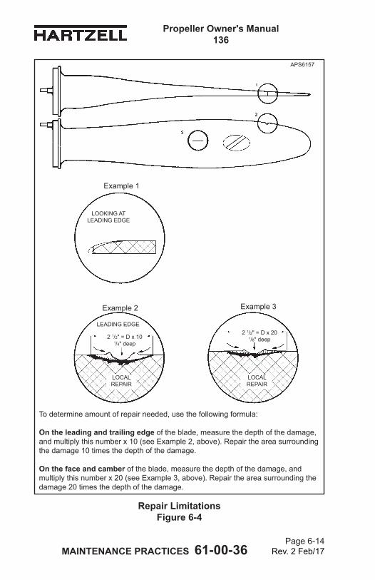
MAINTENANCE PRACTICES 61-00-36 Page 6-14
Rev. 2 Feb/17
Propeller Owner's Manual 136
LOOKING ATLEADING EDGE
LEADING EDGE
2 1/2" = D x 101/4" deep
LOCAL REPAIR
LOCAL REPAIR
Repair Limitations Figure 6-4
To determine amount of repair needed, use the following formula:
On the leading and trailing edge of the blade, measure the depth of the damage, and multiply this number x 10 (see Example 2, above). Repair the area surrounding the damage 10 times the depth of the damage.
On the face and camber of the blade, measure the depth of the damage, and multiply this number x 20 (see Example 3, above). Repair the area surrounding the damage 20 times the depth of the damage.
Example 1
Example 2 Example 3
APS6157
2 1/2" = D x 201/8" deep
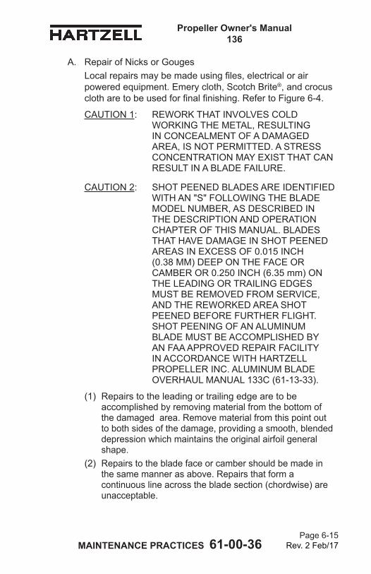
MAINTENANCE PRACTICES 61-00-36 Page 6-15
Rev. 2 Feb/17
Propeller Owner's Manual 136
A. Repair of Nicks or GougesLocal repairs may be made using files, electrical or air powered equipment. Emery cloth, Scotch Brite®, and crocus cloth are to be used for final finishing. Refer to Figure 6-4.
CAUTION 1: REWORK THAT INVOLVES COLD WORKING THE METAL, RESULTING IN CONCEALMENT OF A DAMAGED AREA, IS NOT PERMITTED. A STRESS CONCENTRATION MAY EXIST THAT CAN RESULT IN A BLADE FAILURE.
CAUTION 2: SHOT PEENED BLADES ARE IDENTIFIED WITH AN "S" FOLLOWING THE BLADE MODEL NUMBER, AS DESCRIBED IN THE DESCRIPTION AND OPERATION CHAPTER OF THIS MANUAL. BLADES THAT HAVE DAMAGE IN SHOT PEENED AREAS IN EXCESS OF 0.015 INCH (0.38 MM) DEEP ON THE FACE OR CAMBER OR 0.250 INCH (6.35 mm) ON THE LEADING OR TRAILING EDGES MUST BE REMOVED FROM SERVICE, AND THE REWORKED AREA SHOT PEENED BEFORE FURTHER FLIGHT. SHOT PEENING OF AN ALUMINUM BLADE MUST BE ACCOMPLISHED BY AN FAA APPROVED REPAIR FACILITY IN ACCORDANCE WITH HARTZELL PROPELLER INC. ALUMINUM BLADE OVERHAUL MANUAL 133C (61-13-33).
(1) Repairs to the leading or trailing edge are to be accomplished by removing material from the bottom of the damaged area. Remove material from this point out to both sides of the damage, providing a smooth, blended depression which maintains the original airfoil general shape.
(2) Repairs to the blade face or camber should be made in the same manner as above. Repairs that form a continuous line across the blade section (chordwise) are unacceptable.
MAINTENANCE PRACTICES 61-00-36 Page 6-16
Rev. 2 Feb/17
Propeller Owner's Manual 136
(3) The area of repair should be determined as follows: Leading and trailing edge damage: Depth of nick x 10. Face and camber: Depth of nick x 20. Refer to Figure 6-6.NOTE: Leading edge includes the first 10% of chord
from the leading edge. The trailing edge consists of the last 20% of chord adjacent to the trailing edge.
(4) After filing or sanding of the damaged area, the area must then be polished, first with emery cloth or Scotch Brite® pad, and finally with crocus cloth to remove any traces of filing.
(5) Inspect the repaired area with a 10X magnifying glass. (a) Make sure that indications of the damage, file marks,
or coarse surface finish do not remain.(6) If inspections shows any remaining blade damage,
repeat steps 3.A.(4) and 3.A.(5) until no damage remains. (a) Penetrant inspection is recommended in accordance
with Hartzell Propeller Inc. Standard Practices Manual 202A (61-01-02).
(7) Apply chemical conversion coating and approved paint to the repaired area before returning the blade to service. Refer to the section "Painting After Repair" in this chapter.
MAINTENANCE PRACTICES 61-00-36 Page 6-17
Rev. 2 Feb/17
Propeller Owner's Manual 136
B. Repair of Bent Blades
CAUTION: DO NOT ATTEMPT TO "PRE-STRAIGHTEN" A BLADE BEFORE DELIVERY TO A CERTIFIED PROPELLER REPAIR STATION WITH THE APPROPRIATE RATING. THIS WILL CAUSE THE BLADE TO BE SCRAPPED BY THE REPAIR STATION.
(1) Repair of a bent blade or blades is considered a major repair. This type of repair must be accomplished by a certified propeller repair station with the appropriate rating, and only within approved guidelines.
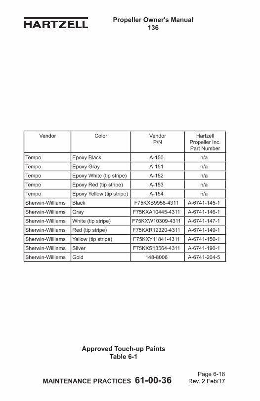
MAINTENANCE PRACTICES 61-00-36 Page 6-18
Rev. 2 Feb/17
Propeller Owner's Manual 136
Approved Touch-up Paints Table 6-1
Vendor Color VendorP/N
Hartzell Propeller Inc. Part Number
Tempo Epoxy Black A-150 n/a
Tempo Epoxy Gray A-151 n/a
Tempo Epoxy White (tip stripe) A-152 n/a
Tempo Epoxy Red (tip stripe) A-153 n/a
Tempo Epoxy Yellow (tip stripe) A-154 n/a
Sherwin-Williams Black F75KXB9958-4311 A-6741-145-1
Sherwin-Williams Gray F75KXA10445-4311 A-6741-146-1
Sherwin-Williams White (tip stripe) F75KXW10309-4311 A-6741-147-1
Sherwin-Williams Red (tip stripe) F75KXR12320-4311 A-6741-149-1
Sherwin-Williams Yellow (tip stripe) F75KXY11841-4311 A-6741-150-1
Sherwin-Williams Silver F75KXS13564-4311 A-6741-190-1
Sherwin-Williams Gold 148-8006 A-6741-204-5
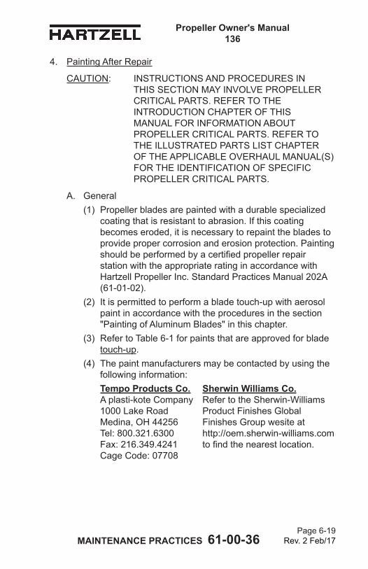
MAINTENANCE PRACTICES 61-00-36 Page 6-19
Rev. 2 Feb/17
Propeller Owner's Manual 136
4. Painting After Repair
CAUTION: INSTRUCTIONS AND PROCEDURES IN THIS SECTION MAY INVOLVE PROPELLER CRITICAL PARTS. REFER TO THE INTRODUCTION CHAPTER OF THIS MANUAL FOR INFORMATION ABOUT PROPELLER CRITICAL PARTS. REFER TO THE ILLUSTRATED PARTS LIST CHAPTER OF THE APPLICABLE OVERHAUL MANUAL(S) FOR THE IDENTIFICATION OF SPECIFIC PROPELLER CRITICAL PARTS.
A. General(1) Propeller blades are painted with a durable specialized
coating that is resistant to abrasion. If this coating becomes eroded, it is necessary to repaint the blades to provide proper corrosion and erosion protection. Painting should be performed by a certified propeller repair station with the appropriate rating in accordance with Hartzell Propeller Inc. Standard Practices Manual 202A (61-01-02).
(2) It is permitted to perform a blade touch-up with aerosol paint in accordance with the procedures in the section "Painting of Aluminum Blades" in this chapter.
(3) Refer to Table 6-1 for paints that are approved for blade touch-up.
(4) The paint manufacturers may be contacted by using the following information:
Tempo Products Co. Sherwin Williams Co. A plasti-kote Company Refer to the Sherwin-Williams 1000 Lake Road Product Finishes Global Medina, OH 44256 Finishes Group wesite at Tel: 800.321.6300 http://oem.sherwin-williams.com Fax: 216.349.4241 to find the nearest location. Cage Code: 07708
MAINTENANCE PRACTICES 61-00-36 Page 6-20
Rev. 2 Feb/17
Propeller Owner's Manual 136
B. Painting of Aluminum Blades
WARNING: CLEANING AGENTS (ACETONE, #700 LACQUER THINNER, AND MEK), ARE FLAMMABLE AND TOXIC TO THE SKIN, EYES, AND RESPIRATORY TRACT. SKIN AND EYE PROTECTION ARE REQUIRED. AVOID PROLONGED CONTACT. USE IN WELL VENTILATED AREA.
CAUTION: ANY REFINISHING PROCEDURE CAN ALTER PROPELLER BALANCE. PROPELLERS THAT ARE OUT OF BALANCE MAY EXPERIENCE EXCESSIVE VIBRATIONS WHILE IN OPERATION.
(1) Using a clean cloth moistened with acetone, #700 lacquer thinner, or MEK, wipe the surface of the blade to remove any contaminants and permit the solvent to evaporate.
(2) Using 120 to 180 grit sandpaper, sand to feather the existing coatings away from the eroded or repaired area.(a) Paint erosion is typically very similar on all blades
in a propeller assembly. If one blade has more extensive paint erosion, e.g., in the tip area, sand all the blades in the tip area to replicate the repair of the most severely damaged blade tip. This practice is essential in maintaining balance after refinishing.
(3) Using acetone, #700 lacquer thinner, or MEK, wipe the surface of the blade and permit the solvent to evaporate.
(4) Before refinishing the blades, apply a corrosion preventive coating to the bare aluminum surface. (a) Tasdip AL 100, Chromicote L-25, Alodine 1200,
Alodine 1200S, Alodine 1201, Iridate 14-2, Birite Guard-Aldip CF, and Brush Alochrome 1200 are approved chemical conversion coatings.
(b) Apply these coatings in accordance with the directions provided by the product manufacturer.
(5) Apply masking material for the anti-icing or de-ice boot and tip stripes, as needed.
MAINTENANCE PRACTICES 61-00-36 Page 6-21
Rev. 2 Feb/17
Propeller Owner's Manual 136
WARNING: FINISH COATINGS ARE FLAMMABLE AND TOXIC TO THE SKIN, EYES AND RESPIRATORY TRACT. SKIN AND EYE PROTECTION ARE REQUIRED. AVOID PROLONGED CONTACT. USE IN A WELL VENTILATED AREA.
CAUTION: APPLY FINISH COATING ONLY TO THE DEGREE REQUIRED TO UNIFORMLY COVER THE REPAIR/EROSION. AVOID EXCESSIVE PAINT BUILD-UP ALONG THE TRAILING EDGE TO AVOID CHANGING THE BLADE PROFILE.
(6) Apply a sufficient amount of finish coating to achieve 2 to 4 mil thickness when dry. (a) Re-coat before 30 minutes, or after 48 hours. (b) If the paint is permitted to dry longer than four (4)
hours, it must be lightly sanded before another coat is applied.
(7) Remove the masking material from the tip stripes and re-mask to permit the tip stripe refinishing, if required.
(8) Apply sufficient tip stripe coating to achieve 2 to 4 mil thickness when dry. (a) Re-coat before 30 minutes, or after 48 hours. (b) If the paint is permitted to dry longer than four (4)
hours, it must be lightly sanded before another coat is applied.
(9) Remove the masking immediately from the anti-icing or de-ice boot and tip stripes, if required.
(10) Optionally, perform dynamic balancing in accordance with the procedures and limitations specified in the Dynamic Balance section of this chapter.
MAINTENANCE PRACTICES 61-00-36 Page 6-22
Rev. 2 Feb/17
Propeller Owner's Manual 136
(This page is intentionally blank.)
MAINTENANCE PRACTICES 61-00-36 Page 6-23
Rev. 2 Feb/17
Propeller Owner's Manual 136
5. Dynamic BalanceA. Overview
CAUTION 1: INSTRUCTIONS AND PROCEDURES IN THIS SECTION MAY INVOLVE PROPELLER CRITICAL PARTS. REFER TO THE INTRODUCTION CHAPTER OF THIS MANUAL FOR INFORMATION ABOUT PROPELLER CRITICAL PARTS. REFER TO THE ILLUSTRATED PARTS LIST CHAPTER OF THE APPLICABLE OVERHAUL MANUAL(S) FOR THE IDENTIFICATION OF SPECIFIC PROPELLER CRITICAL PARTS.
CAUTION 2: IF REFLECTIVE TAPE IS USED FOR DYNAMIC BALANCING, DO NOT APPLY THE TAPE ON EXPOSED BARE METAL OF THE BLADE. THIS WILL PERMIT MOISTURE TO COLLECT UNDER THE TAPE AND CAUSE CORROSION THAT CAN PERMANENTLY DAMAGE THE BLADE. REFLECTIVE TAPE MUST BE REMOVED AFTER DYNAMIC BALANCING IS COMPLETED.
NOTE: Dynamic balance is recommended to reduce vibrations that may be caused by a rotating system (propeller and engine) imbalance. Dynamic balancing can help prolong the life of the propeller, engine, airframe, and avionics.
(1) Dynamic balance is accomplished by using an accurate means of measuring the amount and location of the dynamic imbalance.
(2) The number of balance weights installed must not exceed the limits specified in this chapter.
(3) Follow the dynamic balance equipment manufacturer’s instructions for dynamic balance in addition to the specifications of this section.NOTE: Some engine manufacturers' instructions also
contain information on dynamic balance limits.
MAINTENANCE PRACTICES 61-00-36 Page 6-24
Rev. 2 Feb/17
Propeller Owner's Manual 136
B. Inspection Procedures Before Balancing(1) Visually inspect the propeller assembly before dynamic
balancing.NOTE: The first run-up of a new or overhauled
propeller assembly may leave a small amount of grease on the blades and inner surface of the spinner dome.
(a) Use Stoddard solvent (or equivalent) to completely remove any grease on the blades or inner surface of the spinner dome.
(b) Visually examine each propeller blade assembly for evidence of grease leakage.
(c) Visually examine the inner surface of the spinner dome for evidence of grease leakage.
(2) If there is no evidence of grease leakage, lubricate the propeller in accordance with the Maintenance Practices chapter in this manual. If grease leakage is evident, determine the location of the leak and correct before re-lubricating the propeller and dynamic balancing.
(3) Before dynamic balance, record the number and location of all balance weights.
(4) Static balance is accomplished at a propeller overhaul facility when an overhaul or major repair is performed. NOTE: If static balancing is not accomplished before
dynamic balancing, the propeller may be so severely unbalanced that dynamic balance may not be possible because of measurement equipment limitations.
MAINTENANCE PRACTICES 61-00-36 Page 6-25
Rev. 2 Feb/17
Propeller Owner's Manual 136
C. Modifying Spinner Bulkhead to Accommodate Dynamic Balance Weights
CAUTION: ALL HOLE/BALANCE WEIGHT LOCATIONS MUST TAKE INTO CONSIDERATION, AND MUST AVOID, ANY POSSIBILITY OF INTERFERING WITH THE ADJACENT AIRFRAME, PROPELLER ICE PROTECTION SYSTEM, AND ENGINE COMPONENTS.
(1) It is recommended that balance weights be placed in a radial location on aluminum spinner bulkheads that have not been previously drilled.
(2) The radial location should be outboard of the de-ice slip ring or bulkhead doubler and inboard of the bend where the bulkhead creates the flange surface to attach the spinner dome.
(3) Twelve equally spaced locations are recommended for weight attachment.
(4) Installing nut plates (10-32 thread) of the type used to attach the spinner dome will permit convenient balance weight attachment on the engine side of the bulkhead.
(5) Alternatively, drilling holes for use with the AN3-( ) type bolts with self-locking nuts is permitted.
(6) Chadwick-Helmuth Manual AW-9511-2, “The Smooth Propeller”, specifies several generic bulkhead rework procedures. These are permitted if they comply with the conditions specified herein.
MAINTENANCE PRACTICES 61-00-36 Page 6-26
Rev. 2 Feb/17
Propeller Owner's Manual 136
D. Placement of Balance Weights for Dynamic Balance(1) The preferred method of attachment of dynamic balance
weights is to add the weights to the spinner bulkhead.NOTE: Many spinner bulkheads have factory installed
self-locking nut plates provided for this purpose.(2) If the location of static balance weights has not been
altered, subsequent removal of the dynamic balance weights will return the propeller to its original static balance condition.
(3) Use only stainless or plated steel washers as dynamic balance weights on the spinner bulkhead.
(4) A maximum of six AN970 style washers weighing up to approximately 1.0 ounce (28.0 g) may be installed at any one location. NOTE: The dimensions of an AN970 washer are:
ID 0.203 inch (5.16 mm), OD 0.875 inch (22.23 mm), and thickness 0.063 inch (1.59 mm).
(5) Install weights using aircraft quality #10-32 or AN-3( ) type screws or bolts.
(6) Balance weight screws attached to the spinner bulkhead must protrude through the self-locking nuts or nut plates a minimum of one thread and a maximum of four threads.
CAUTION: IF REFLECTIVE TAPE IS USED FOR DYNAMIC BALANCING, REMOVE THE TAPE IMMEDIATELY UPON COMPLETION. TAPE THAT REMAINS ON THE BLADE WILL PERMIT MOISTURE TO COLLECT UNDER THE TAPE AND CAUSE CORROSION THAT CAN PERMANENTLY DAMAGE THE BLADE.
(7) Unless otherwise specified by the engine or airframe manufacturer, Hartzell Propeller Inc. recommends that the propeller be dynamically balanced to a reading of 0.2 IPS, or less.
(8) If reflective tape is used for dynamic balancing, remove the tape immediately after balancing is completed.
(9) Make a record in the propeller logbook of the number and location of dynamic balance weights, and static balance weights if they have been reconfigured.
MAINTENANCE PRACTICES 61-00-36 Page 6-27
Rev. 2 Feb/17
Propeller Owner's Manual 136
6. Propeller Low Pitch Setting
WARNING 1: RPM ADJUSTMENTS MUST BE MADE WITH REFERENCE TO A CALIBRATED TACHOMETER. AIRCRAFT MECHANICAL TACHOMETERS DEVELOP ERRORS OVER TIME, AND SHOULD BE PERIODICALLY RECALIBRATED TO MAKE SURE THE PROPER RPM IS DISPLAYED.
WARNING 2: LOW PITCH BLADE ANGLE ADJUSTMENTS MUST BE MADE IN CONSULTATION WITH THE APPLICABLE TYPE CERTIFICATE OR SUPPLEMENTAL TYPE CERTIFICATE HOLDERS MAINTENANCE DATA.
CAUTION: INSTRUCTIONS AND PROCEDURES IN THIS SECTION MAY INVOLVE PROPELLER CRITICAL PARTS. REFER TO THE INTRODUCTION CHAPTER OF THIS MANUAL FOR INFORMATION ABOUT PROPELLER CRITICAL PARTS. REFER TO THE ILLUSTRATED PARTS LIST CHAPTER OF THE APPLICABLE OVERHAUL MANUAL(S) FOR THE IDENTIFICATION OF SPECIFIC PROPELLER CRITICAL PARTS.
A. Low Pitch(1) The propeller low pitch stop is set at the factory to the
aircraft TC or STC Holder's requirements and should not require any additional adjustment. The TC or STC Holder provides the required low pitch stop blade angle and may also provide the acceptable RPM range for a maximum power static condition. Be aware that the aircraft TC or STC holder may specify the static RPM to be less than the RPM to which the engine is rated.
(2) An overspeed at the maximum power static condition may indicate that the propeller low-pitch blade angle is set too low or that the governor is improperly adjusted.
MAINTENANCE PRACTICES 61-00-36 Page 6-28
Rev. 2 Feb/17
Propeller Owner's Manual 136
(3) An underspeed during the maximum power static condition may be caused by any one or a combination of the following: The propeller low pitch blade angle is too high; the governor is improperly adjusted; the engine is not producing rated power.
MAINTENANCE PRACTICES 61-00-36 Page 6-29
Rev. 2 Feb/17
Propeller Owner's Manual 136
7. Propeller Pitch SettingsA. High Pitch Stop
(1) The high pitch stop is set at the factory per the aircraft manufacturer's recommendations. This stop is adjustable only by a certified propeller repair station with the appropriate rating or the Hartzell Propeller Inc. factory.
B. Low Pitch Stop (1) The low pitch stop is set at the factory per the aircraft
manufacturer's recommendations. This stop is adjustable only by a certified propeller repair station with the appropriate rating or the Hartzell Propeller Inc. factory.
C. Reverse Pitch Stop (1) The reverse pitch stop is set at the factory per the
aircraft manufacturer's recommendations. This stop is adjustable only by a certified propeller repair station with the appropriate rating or the Hartzell Propeller Inc. factory.
8. Propeller Ice Protection SystemsA. Electric De-ice System
(1) Consult the Pilot Operating Handbook (including all supplements) regarding flight into conditions of known icing. The aircraft may not be certificated for flight in known icing conditions, even though propeller de-ice equipment is installed.
(2) Refer to the Anti-ice and De-ice Systems chapter of this manual for operational checks of the de-ice system.
B. Anti-ice System(1) Consult the Pilot Operating Handbook (including all
supplements) regarding flight into conditions of known icing. The aircraft may not be certificated for flight in known icing conditions, even though propeller anti-ice equipment is installed.
(2) Refer to the Aircraft Maintenance Manual for operational/functional checks of the anti-ice system.
MAINTENANCE PRACTICES 61-00-36 Page 6-30
Rev. 2 Feb/17
Propeller Owner's Manual 136
9. Tachometer Calibration
WARNING: OPERATION WITH AN INACCURATE TACHOMETER CAN CAUSE RESTRICTED RPM OPERATION AND DAMAGING HIGH STRESSES. PROPELLER LIFE WILL BE SHORTENED AND COULD CAUSE CATASTROPHIC FAILURE.
A. All engine/propeller combinations have certain frequencies (RPM) at which the propeller blade stresses begin to reach design limits. (1) In most cases, these frequencies are above the
maximum rated RPM of the engine. (2) Some engine/propeller combinations have certain
ranges of RPM that are less than maximum engine speed, where stresses are at a level considered too high for continuous operation. This results in a “placarded range” where continuous operation is not permitted.
(3) In other cases, the maximum permitted stresses occur at an RPM only slightly above the maximum engine RPM.
(4) For these reasons, it is very important to accurately monitor engine speed.
B. The accuracy of the tachometer is critical to the safe operation of the aircraft. (1) Some tachometers have been found to be in error by as
much as 200 RPM. (2) Operating the aircraft with an inaccurate tachometer
could cause continued operation in a placarded range of unacceptable high stresses, including repeatedly exceeding the maximum engine RPM.
(3) Continuous operation in a placarded range of unacceptable high stresses subjects the propeller to a high amplitude frequency that causes stresses higher than the design limits.
(4) Stresses that are higher than the design limits will shorten the life of the propeller and could cause a catastrophic failure.
MAINTENANCE PRACTICES 61-00-36 Page 6-31
Rev. 2 Feb/17
Propeller Owner's Manual 136
C. Tachometer Calibration(1) Hartzell Propeller Inc. recommends that propeller
owners/operators calibrate the engine tachometer in accordance with the National Institute of Standards and Technology (NIST) or similar national standard (traceable).
(2) Contact Hartzell Propeller Inc. if it is determined that a propeller was operated in a restricted RPM range because of a tachometer error.
MAINTENANCE PRACTICES 61-00-36 Page 6-32
Rev. 2 Feb/17
Propeller Owner's Manual 136
(This page is intentionally blank.)
ANTI-ICE AND DE-ICE SYSTEMS 61-00-36Page 7-1
Rev. 2 Feb/17
Propeller Owner's Manual 136
ANTI-ICE AND DE-ICE SYSTEM - CONTENTS
1. Introduction .............................................................................. 7-3A. Propeller De-ice System .................................................... 7-3B. Propeller Anti-ice System .................................................. 7-3
2. System Description .................................................................. 7-4A. De-ice System ................................................................... 7-4B. Anti-ice System .................................................................. 7-5
3. De-ice System Operation Checks ............................................ 7-6
4. Anti-ice System Operational/Functional Checks ...................... 7-6
5. De-ice and Anti-ice System Inspections ................................... 7-7A. De-ice System Inspections ................................................ 7-7B. Anti-ice System Inspections .............................................. 7-7
6. De-ice and Anti-ice System Troubleshooting ........................... 7-8A. De-ice System Troubleshooting ......................................... 7-8B. Anti-ice System Troubleshooting ....................................... 7-8
ANTI-ICE AND DE-ICE SYSTEMS 61-00-36Page 7-2
Rev. 2 Feb/17
Propeller Owner's Manual 136
(This page is intentionally blank.)
ANTI-ICE AND DE-ICE SYSTEMS 61-00-36Page 7-3
Rev. 2 Feb/17
Propeller Owner's Manual 136
1. IntroductionA. Propeller De-ice System
(1) A propeller de-ice system is a system that removes ice after it forms on the propeller blades. A de-ice system uses electrical heating elements to melt the ice layer next to the blades, permitting the ice to be thrown from the blade by centrifugal force. Blades are alternately heated and permitted to cool as the current is applied and removed automatically by the de-ice system timer.
(2) System components include a timer or cycling unit, electrical slip ring(s), brush block assembly, and blade mounted de-ice boots.
B. Propeller Anti-ice System(1) A propeller anti-ice system is a system that prevents
formation of ice on propeller surfaces. An anti-ice system dispenses a fluid that mixes with, and reduces the freezing point of, moisture on the propeller blades. The mixture may then flow off the blades before it forms ice.
(2) System components include a fluid tank, pump, slinger ring, blade mounted fluid anti-icing boots, and a fluid dispensing tube that is located at each blade anti-icing boot.
ANTI-ICE AND DE-ICE SYSTEMS 61-00-36Page 7-4
Rev. 2 Feb/17
Propeller Owner's Manual 136
2. System DescriptionA. De-ice System
NOTE: Because of the wide variances of various de-ice systems, the following description is general in nature. Consult the airframe manufacturer’s manual for a description of your specific de-ice system and controls.
(1) The de-ice system is controlled by the pilot via a cockpit control switch. This switch applies electrical power to the de-ice system, which will operate as long as the switch is in the ON position. Depending upon the system, another set of cockpit controls may be available. One of these controls is a mode selector, which permits the pilot to select two cycling speeds, for heavy or light icing conditions. Some systems on twin engine aircraft have a switch which provides a full de-ice mode, which permits the pilot to de-ice both propellers simultaneously. This switch may only be used for short periods and is used when ice builds up on the propeller before the system is turned on.
(2) An ammeter, which indicates current drawn by the system, is normally located near the de-ice system switches. This meter may indicate total system load, or a separate meter may be supplied for each propeller.
(3) A timer, which is turned off and on by the cockpit control, is used to sequence the de-ice system. This timer turns the de-ice system on and off in proper sequence, controlling the heating interval to each propeller for even de-icing.
(4) A brush block, which is mounted on the engine immediately behind the propeller, supplies electrical current to the de-ice boot on each propeller blade via a slip ring. The slip ring is normally mounted on the spinner bulkhead.
(5) When the pilot places the de-ice system cockpit control switch in the ON position, the system timer begins to operate. As the timer sequences, power is delivered to a power relay. The power relay delivers high current to the brush block and slip ring. Each propeller is de-iced in turn by the timer.
ANTI-ICE AND DE-ICE SYSTEMS 61-00-36Page 7-5
Rev. 2 Feb/17
Propeller Owner's Manual 136
B. Anti-ice System(1) The anti-ice system is controlled by the pilot via a
cockpit mounted rheostat. This rheostat operates a pump that pumps anti-ice fluid from the tank at a controlled rate.
(2) The anti-ice fluid is delivered through a filter, a check valve, and then through tubing to a slinger ring located at the rear of the spinner bulkhead. The anti-ice fluid is dispensed into the rotating slinger ring, which holds the fluid in a curved channel by centrifugal force. The fluid then flows out of the slinger ring through feed tubes which are welded to the slinger ring, and then out onto the blade anti-icing boots.
(3) The blade anti-icing boots are ridged rubber sheets that are glued to the leading edge of the blades. The ridges in the anti-icing boots direct the fluid out onto the blades and permit for an even distribution of the anti-ice fluid across the blades.
ANTI-ICE AND DE-ICE SYSTEMS 61-00-36Page 7-6
Rev. 2 Feb/17
Propeller Owner's Manual 136
3. De-ice System Operational ChecksA. Operational checks of the de-ice system should be
performed in accordance with the following Hartzell Propeller Inc. manuals that are available on the Hartzell Propeller Inc. website at www.hartzellprop.com:
(1) Hartzell Propeller Inc. Manual 181 (30-60-81) - Propeller Ice Protection System Component Maintenance Manual
(2) Hartzell Propeller Inc. Manual 182 (61-12-82) - Propeller Electrical De-ice Boot Removal and Installation Manual
B. Components supplied by Hartzell Propeller Inc. for use in de-ice systems are found in the following manuals that are available on the Hartzell Propeller Inc. website at www.hartzellprop.com:
(1) Hartzell Propeller Inc. Manual 180 (30-61-80) - Propeller Ice Protection System Manual
(2) Hartzell Propeller Inc. Manual 182 (61-12-82) - Propeller Electrical De-ice Boot Removal and Installation Manual
4. Anti-ice System Operational/Functional ChecksA. Operational/functional checks of the anti-ice system should
be performed in accordance with the Aircraft Maintenance Manual and the following Hartzell Propeller Inc. manual that is available on the Hartzell Propeller Inc. website at www.hartzellprop.com:
(1) Hartzell Propeller Inc. Manual 181 (30-61-81) - Propeller Ice Protection System Component Maintenance Manual
B. Components supplied by Hartzell Propeller Inc. for use in anti-ice systems are found in the following manuals that are available on the Hartzell Propeller Inc. website at www.hartzellprop.com:
(1) Hartzell Propeller Inc. Manual 180 (30-61-80) - Propeller Ice Protection System Manual
(2) Hartzell Propeller Inc. Manual 183 (61-12-83) - Propeller Anti-icing Boot Removal and Installation Manual
ANTI-ICE AND DE-ICE SYSTEMS 61-00-36Page 7-7
Rev. 2 Feb/17
Propeller Owner's Manual 136
5. De-ice and Anti-ice System InspectionsThe inspections detailed below are made on a regular basis, either before flight, during the 100 hour inspection, or if a problem is noted. Possible corrections to problems discovered during inspections, additional inspections, and limits are detailed in the following Hartzell Propeller Inc. manuals.A. De-ice System Inspections
(1) Perform inspections in accordance with the following Hartzell Propeller Inc. manuals, which are available on the Hartzell Propeller Inc. website at www.hartzellprop.com:
(a) Hartzell Propeller Inc. Manual 181 (30-60-81) - Propeller Ice Protection System Component Maintenance Manual
(b) Hartzell Propeller Inc. Manual 182 (61-12-82) - Propeller Electrical De-ice Boot Removal and Installation Manual
B. Anti-ice System Inspections(1) Perform inspections in accordance with the Aircraft
Maintenance Manual or the following Hartzell Propeller Inc. Manuals, which are available on the Hartzell Propeller Inc. website at www.hartzellprop.com:
(a) Hartzell Propeller Inc. Manual 181 (30-60-81) - Propeller Ice Protection System Component Maintenance Manual
(b) Hartzell Propeller Inc.Manual 183 (61-12-83) - Propeller Anti-icing Boot Removal and Installation Manual
ANTI-ICE AND DE-ICE SYSTEMS 61-00-36Page 7-8
Rev. 2 Feb/17
Propeller Owner's Manual 136
6. De-ice and Anti-ice System TroubleshootingA. De-ice System Troubleshooting
(1) Perform troubleshooting in accordance with the following Hartzell Propeller Inc. manuals, which are available on the Hartzell Propeller Inc. website at www.hartzellprop.com:
(a) Hartzell Propeller Inc. Manual No. 181 (30-60-81) - Propeller Ice Protection System Component Maintenance Manual
(b) Hartzell Propeller Inc. Manual No. 182 (61-12-82) - Propeller Electrical De-ice Boot Removal and Installation Manual
B. Anti-ice System Troubleshooting(1) Perform troubleshooting in accordance with the
following Hartzell Propeller Inc. manuals, which are available on the Hartzell Propeller Inc. website at www.hartzellprop.com:
(a) Hartzell Propeller Inc. Manual No. 181 (30-60-81) - Propeller Ice Protection System Component Maintenance Manual
(b) Hartzell Propeller Inc. Manual No. 183 (61-12-83) - Propeller Anti-icing Boot Removal and Installation Manual
RECORDS 61-00-36Page 8-1
Rev. 2 Feb/17
Propeller Owner’s Manual 136
RECORDS - CONTENTS
1. Introduction ................................................................................8-3
2. Record Keeping .........................................................................8-3A. Information to be Recorded ...................................................8-3
RECORDS 61-00-36Page 8-2
Rev. 2 Feb/17
Propeller Owner’s Manual 136
(This page is intentionally blank.)
RECORDS 61-00-36Page 8-3
Rev. 2 Feb/17
Propeller Owner’s Manual 136
1. IntroductionFederal Aviation Regulations require that a record be kept of any repairs, adjustments, maintenance, or required inspections performed on a propeller or propeller system.This chapter provides a method for maintaining these records. It also provides a location for recording information that can aid the service technician in maintaining the propeller system.
2. Record KeepingA. Information to be Recorded
(1) Information which is required to be recorded is listed in Part 43 of the U.S. Federal Aviation Regulations.
(2) The log book may also be used to record:(a) Propeller position (on aircraft)(b) Propeller model(c) Propeller serial number(d) Blade design number(e) Blade serial numbers(f) Spinner assembly part number(g) Propeller pitch range(h) Aircraft information (aircraft type, model, serial
number and registration number)(i) Dynamic balance information(j) Modificationofthelowpitchstophardware(k) Maintenance activity(l) Foreign object strike incident and corrective action(m) Lightning strike incident and corrective action(n) Overspeed event and corrective action(o) Significanteventandcorrectiveaction(p) Position 3 oil pressure. Refer to
Figure 3-16.
RECORDS 61-00-36Page 8-4
Rev. 2 Feb/17
Propeller Owner’s Manual 136
(This page is intentionally blank.)