Embed Size (px)
Citation preview

270
Balal1, G. A. Pinhasi
2, Y. Pinhasi
1
1Department of Electrical and Electronic Engineering, Ariel University Center of Samaria
2Department of Chemical Engineering and Biotechnology, Ariel University Center of Samaria
P.O. Box 3, Ariel 40700, Israel, Tel. +972 (3) 9066272, e-mail: [email protected]
ABSTRACT
The demand for high resolution directive RADARS the lack of wide frequency bands within the
conventional spectrum causes one to seek bandwidth in the higher millimeter and sub- millimeter
wave spectrum at Extremely High Frequencies (EHF) above 30GHz. Since the EHF band covers a
relatively large spectrum which is free of users, enables the utilization of ultra wideband signals,
resulting in better resolution in the longitudinal and transverse dimensions. The fact that the
millimeter and sub-millimeter RF sources are producing low radiation power, the method of
continuous wave wide band frequency modulation becomes the natural technique for remote
sensing and detection.
One of the principal challenges in realizing ultra wide band RADARs in the EHF band is
phenomenon occurring during electromagnetic wave propagation through the atmosphere. Space-
frequency theory for the propagation of an ultra-wide band radiation in a inhomogeneous dielectric
media is presented. Characterization of the atmospheric medium is via its refractivity leading to a
transfer function, which describes the changing response of the medium in the frequency domain.
This description enables the consideration of broadband FMCW signals taking into account
inhomogeneous absorptive and dispersive effects of the medium.
1. INTRODUCTION
During the past two decades, millimeter wave radar systems operating in FMCW mode have been
intensively developed for a variety of applications such as collision avoidance in automobile [1-3]
remote sensing [4,5] concealed weapon detection for homeland security needs [6-8] and other
related areas. The choice of operating frequency and modulation bandwidth is the critical issue in
design FMCW systems and greatly depends on atmospheric propagation and penetration depth
through various materials.
The demand for broadband RADAR systems and the deficiency of wide frequency bands
within the conventional spectrum, require utilization of higher frequencies and millimeter-wave
spectrum at the Extremely High Frequencies (EHF) above 30GHz. In addition to the fact that the
EHF band (30-300GHz) covers a wide range, which is relatively free of spectrum users, it offers
many advantages for high resolution RADAR systems. Among the practical advantages of using
millimeter and sub- millimeter wavelengths RADAR systems is the ability to employ smaller
transmitting and receiving antennas.
Some of the principal challenges in realizing modern RADAR at the EHF band are the effects
emerging when the electromagnetic radiation propagates through the atmosphere. When millimeter-
wave radiation passes through the atmosphere, it suffers from selective molecular absorption [9-14].
Several empirical and analytical models were suggested for estimating the millimeter and sub-
millimeter wave transmission of the atmospheric medium. The transmission characteristics of the
PROPAGATION OF ULTRA-WIDE BAND 'CHIRPED' MILLIMETER
AND TERA-HERTZ WAVES IN THE ATMOSPHERIC MEDIUM
271
atmosphere at the EHF band, as shown in Figure 1 was calculated with the millimeter propagation
model (MPM), developed by Liebe [15-18].
The inhomogeneous transmission in a band of frequencies causes absorptive and dispersive
effects in the amplitude and in phase of wide-band signals transmitted in the EHF band [19]. These
effects should be taken into account in the design of broadband FMCW RADAR systems [20]. In
this paper, we develop a general approach for studying wideband RADARs operating in the EHF
band. The theory is used to compare between analytical and numerical models. The MPM model
[15-16] is used in the numerical model for calculation of atmospheric characteristics in the
frequency domain. The resulting propagation factor is calculated numerically, enabling one to deal
with ultra-wide band arbitrary signals.
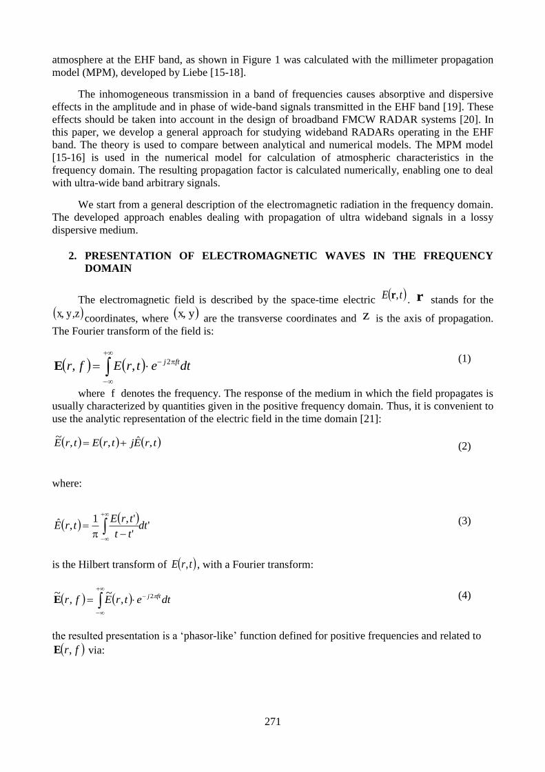
We start from a general description of the electromagnetic radiation in the frequency domain.
The developed approach enables dealing with propagation of ultra wideband signals in a lossy
dispersive medium.
2. PRESENTATION OF ELECTROMAGNETIC WAVES IN THE FREQUENCY
DOMAIN
The electromagnetic field is described by the space-time electric tE ,r . r stands for the
zy,x, coordinates, where yx, are the transverse coordinates and z is the axis of propagation.
The Fourier transform of the field is:
dtetrEfr ftj2,,E (1)
where f denotes the frequency. The response of the medium in which the field propagates is
usually characterized by quantities given in the positive frequency domain. Thus, it is convenient to
use the analytic representation of the electric field in the time domain [21]:
trEjtrEtrE ,ˆ,,~
(2)
where:
''
',1,ˆ dt
tt
trEtrE
(3)
is the Hilbert transform of trE , , with a Fourier transform:
dtetrEfr ftj 2,~
,~E
(4)
the resulted presentation is a ‘phasor-like’ function defined for positive frequencies and related to
fr,E via:

272
00
0,2,
~
f
ffrfr
EE
(5)
Since the electromagnetic signal is real (i.e. trEtrE ,,* ), its Fourier transform satisfies
frfr ,,* EE . Consequently, the Fourier transform can be decomposed in terms of the
phasor-like function according to:
frfrfr ,~
2
1,
~
2
1, *
EEE (6)
The time domain field is obtained by inverse Fourier transformation of Eq. (6):
0
22 ,~
Re,, dfefrdfefrtrE ftjftj EE (7)
3. PROPAGATION OF LINEAR FM SIGNAL IN A DIELECTRIC MEDIA
In FMCW radar (see Figure 1), a linear frequency modulated signal ("chirp") is transmitted toward
the target. The instantaneous frequency of the transmission is changing linearly according to:
tT
fftf
sweep
c
(8)
where the carrier frequency is cf and the frequency span f
divided by the sweep time sweepT is the
compression ratio of the linear FM signal. The transmitted signal can be presented as a carrier wave
at frequency cf modulated by a wide-band signal:
tfj
TTcetAtE
2Re)( (9)
here tAT is a complex envelope, representing the base-band modulating signal. In the case of
linear FM, the complex amplitude of the 'chirp' is:
2exp t
T
fjtA
sweep
T (10)
273
Fourier transform of the transmitted field (9) yields:
cTcTT fffff *
2
1
2
1)( AAE (11)
where fTA is the Fourier transform of the complex envelope tAT . The transmitted signal
directed to the target located at a distance d is scattered back and arrived to the receiver. After
propagating along a total distance d2 in the dielectric medium, the phasor-like field presentation in
the positive frequency domain is given by:
dfkj
cTRzefff
2
)(~
AE (12)
where fkz is the complex propagation factor of the electromagnetic field in the medium. In order
to find the field in the time domain, we substitute Eq. (12) into expression (7) and bring the result to
the form:
tfj
TRcetAtE
2Re)( (13)
where the complex envelope of the received signal is:
dfeftA
dffkj
TRcz2
A (14)
The delayed echoes, reflected from the target, are mixed with its local oscillator (LO) signal, and
then filtered to remove higher-order harmonics. The resulted signal at the output of the filter is:
dfeftAtAtAtV
dffkj
TTRTcz2**~
A (15)
The detected signal tV~
is at baseband or intermediate frequencies. The distance to the target is
measured via the instantaneous frequency resulted from the derivative:
tV
tVarctg
dt
dtfIF ~
Re
~Im
2
1
(16)
If the signal is propagating in vacuum, i.e. when the index of refraction is a constant 1cfn
, the
propagation factor is cffk z /2
. As expected, the detected signal resulted from Eq. (15) is a
pure tone:

274
c
df
c
d
T
fjt
c
d
T
fjtV c
sweep
f
sweep
m
22
222exp
~2
(17)
at a single frequency proportional to the distance to the target:
c
d
T
ff
sweep
m
2 (18)
Dispersive behavior of atmospheric media will cause deviations in the frequency calculated in (16),
and thus produce errors in the measured distance. We now demonstrate the atmospheric effects on
the resulted measured distance in millimeter wavelengths.
LPF
VCO
Product Detector
ET(t)
ER(t)=ET(t-) 0 T T+
fpeak
fm
V(t)
Figure 1: Linear FM RADAR
4. MILLIMETER WAVE PROPAGATTION IN THE ATMOSPHERE
The millimeter wave propagation model is based on a complex presentation of the refraction index:
6101 fNfn (19)
where )('')(')( 0 fjNfNNfN is the complex refractivity given in PPM [15-16]. The
propagation factor fk can be written in terms of the index of refraction:
275
f
f
f
fNc
fN
c
ffN
c
fjfn
c
ffk
66
0
6 10'2
1012
10''22
(20)
where c is the speed of light in vacuum. The attenuation factor is:
610''2
)(Im
fNc
ffkf z
(21)
and the wavenumber of the propagating wave is given by:
f
z fNc
fN
c
ffkf
66
0 10'2
1012
)(Re (22)
The transmission characteristics of the atmosphere at the EHF band, as shown in Figure 2 was
calculated with the millimeter propagation model (MPM), developed by Liebe [15-18]. Curves are
drawn for several values of relative-humidity (RH), assuming clear sky and no rain. Inspection of
Figure 2 reveals absorption peaks at 22GHz and 183GHz, where resonance absorption of water (
OH2 ) occurs, as well as absorption peaks at 60GHz and 119GHz, due to absorption resonances of
oxygen ( 2O ) [22-24]. Between these frequencies, minimum attenuation is obtained at 35GHz (Ka-
band), 94GHz (W-band), 130GHz and 220GHz, which are known as atmospheric transmission
'windows' [12].
The oxygen absorption band, in the vicinity of 60GHz is especially interesting. The unused
frequency space and the high attenuation due to oxygen absorption (-15dB/Km) make this
frequency range naturally fitting for local broadband wireless links with small reuse distances [25].
A number of administrations have even allocated this spectrum as an unlicensed one and allow
short-range, broadband communications technologies. Equipment to utilize this band is starting to
become available.

276
Figure 2: Millimeter wave (a) attenuation coefficient fe )log(20 in [dB/Km]
and (b) wavenumber increment f in [Deg./Km]
for various values of relative humidity (RH).
277
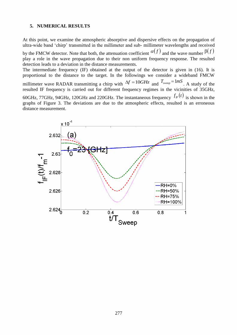
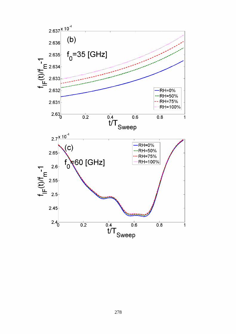
5. NUMERICAL RESULTS
At this point, we examine the atmospheric absorptive and dispersive effects on the propagation of
ultra-wide band ‘chirp’ transmitted in the millimeter and sub- millimeter wavelengths and received
by the FMCW detector. Note that both, the attenuation coefficient f and the wave number f
play a role in the wave propagation due to their non uniform frequency response. The resulted
detection leads to a deviation in the distance measurements.
The intermediate frequency (IF) obtained at the output of the detector is given in (16). It is
proportional to the distance to the target. In the followings we consider a wideband FMCW
millimeter wave RADAR transmitting a chirp with GHzf 10 and mSTsweap 1
. A study of the
resulted IF frequency is carried out for different frequency regimes in the vicinities of 35GHz,
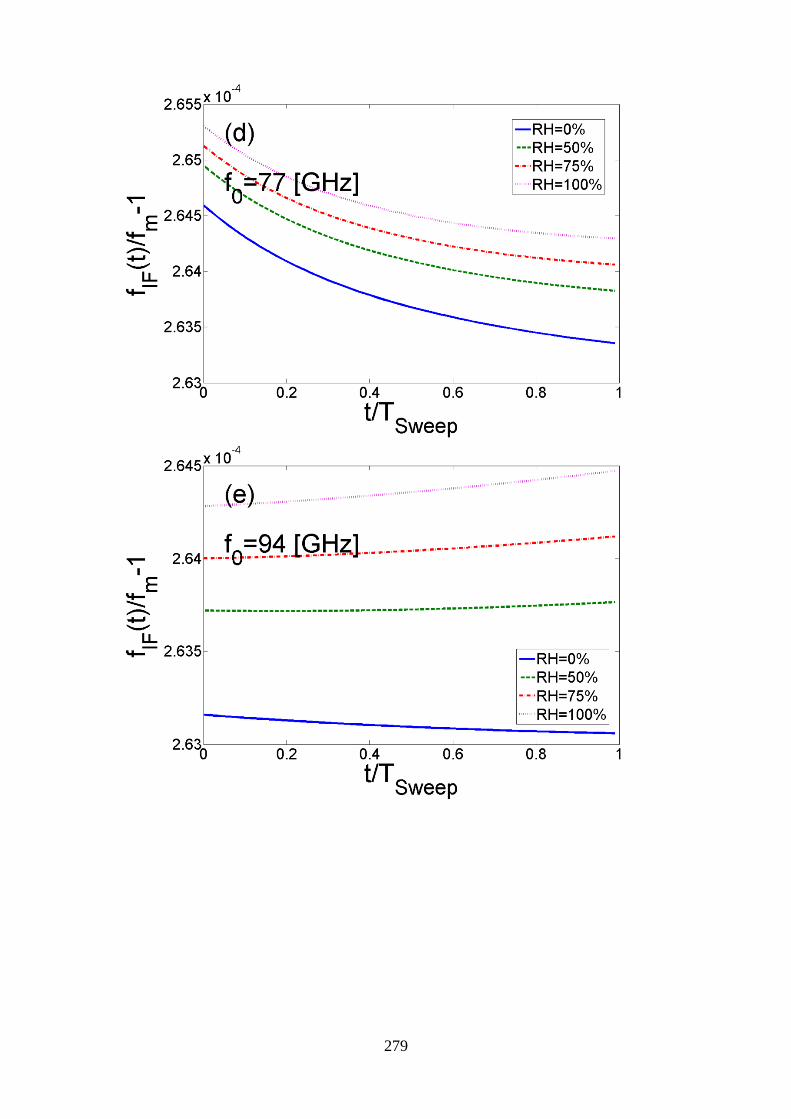
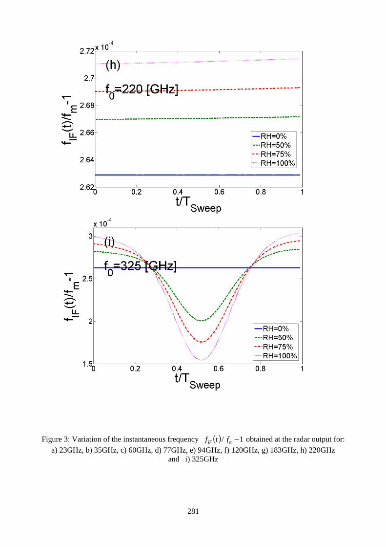
60GHz, 77GHz, 94GHz, 120GHz and 220GHz. The instantaneous frequency tfIF is shown in the
graphs of Figure 3. The deviations are due to the atmospheric effects, resulted is an erroneous
distance measurement.
278
279

280
281
Figure 3: Variation of the instantaneous frequency 1/ mIF ftf obtained at the radar output for:
a) 23GHz, b) 35GHz, c) 60GHz, d) 77GHz, e) 94GHz, f) 120GHz, g) 183GHz, h) 220GHz
and i) 325GHz
282
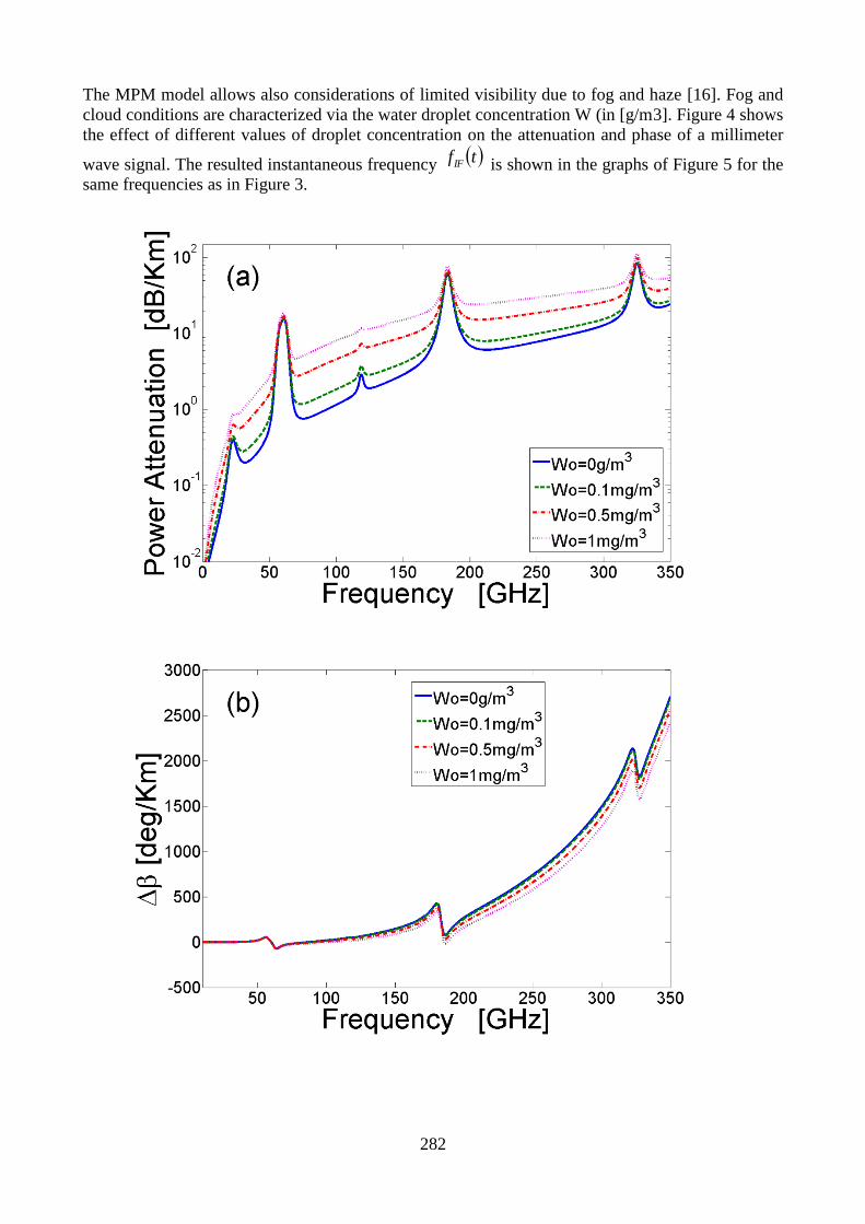
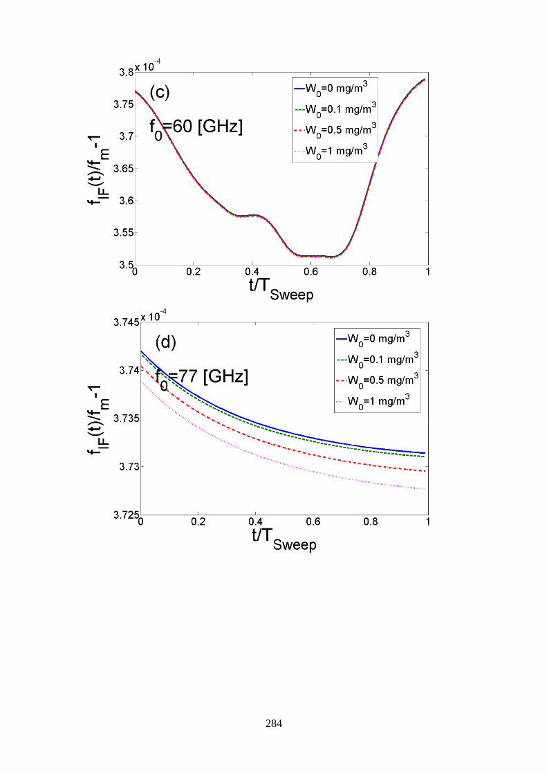
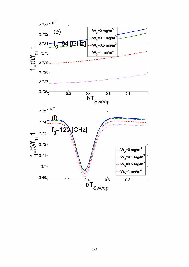
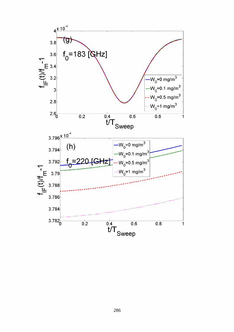
The MPM model allows also considerations of limited visibility due to fog and haze [16]. Fog and
cloud conditions are characterized via the water droplet concentration W (in [g/m3]. Figure 4 shows
the effect of different values of droplet concentration on the attenuation and phase of a millimeter
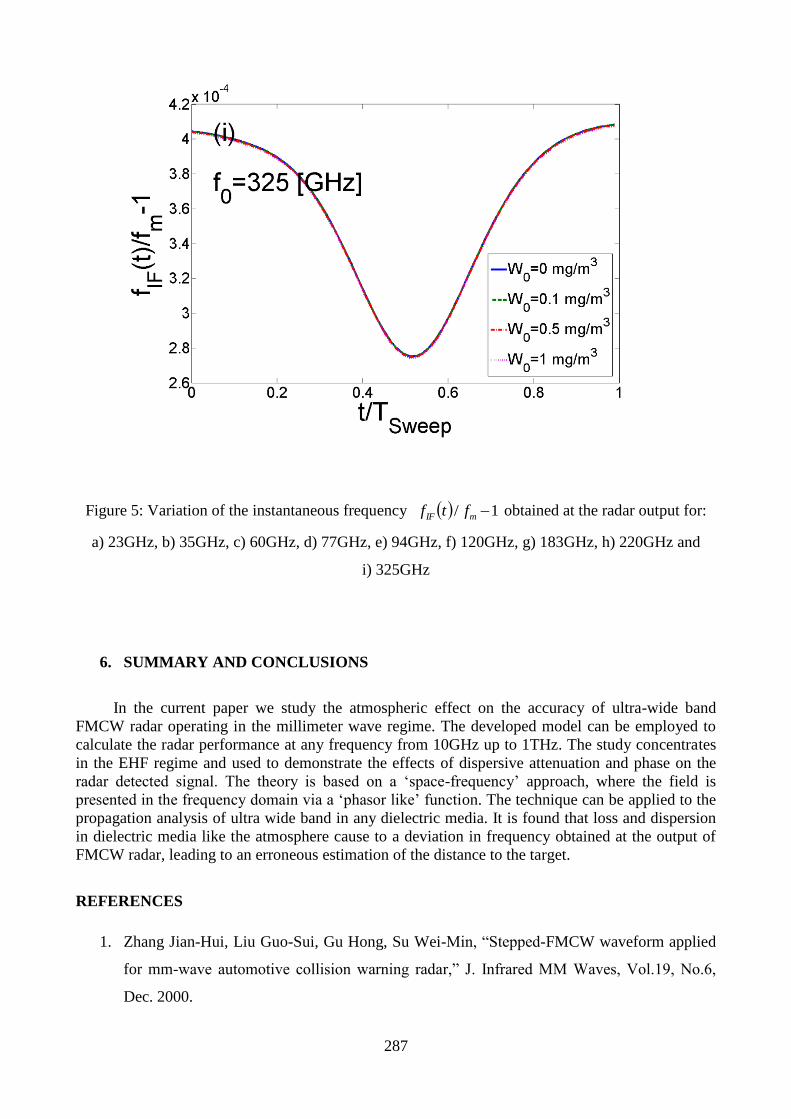
wave signal. The resulted instantaneous frequency tfIF is shown in the graphs of Figure 5 for the
same frequencies as in Figure 3.
283
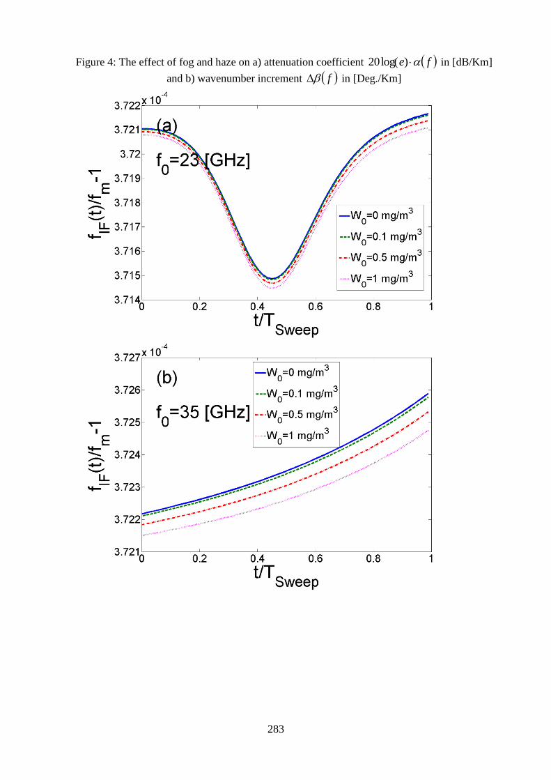
Figure 4: The effect of fog and haze on a) attenuation coefficient fe )log(20 in [dB/Km]
and b) wavenumber increment f in [Deg./Km]
284
285
286
287
Figure 5: Variation of the instantaneous frequency 1/ mIF ftf obtained at the radar output for:
a) 23GHz, b) 35GHz, c) 60GHz, d) 77GHz, e) 94GHz, f) 120GHz, g) 183GHz, h) 220GHz and
i) 325GHz
6. SUMMARY AND CONCLUSIONS
In the current paper we study the atmospheric effect on the accuracy of ultra-wide band
FMCW radar operating in the millimeter wave regime. The developed model can be employed to
calculate the radar performance at any frequency from 10GHz up to 1THz. The study concentrates
in the EHF regime and used to demonstrate the effects of dispersive attenuation and phase on the
radar detected signal. The theory is based on a ‘space-frequency’ approach, where the field is
presented in the frequency domain via a ‘phasor like’ function. The technique can be applied to the
propagation analysis of ultra wide band in any dielectric media. It is found that loss and dispersion
in dielectric media like the atmosphere cause to a deviation in frequency obtained at the output of
FMCW radar, leading to an erroneous estimation of the distance to the target.
REFERENCES
1. Zhang Jian-Hui, Liu Guo-Sui, Gu Hong, Su Wei-Min, “Stepped-FMCW waveform applied
for mm-wave automotive collision warning radar,” J. Infrared MM Waves, Vol.19, No.6,
Dec. 2000.
288
2. I. Gresham, N. Jain, T. Budka, A. Alexanian, N. Kinayman, B. Zeigler, S. Brown, and P.
Staecker, "A 76-77GHz Pulsed-Doppler Radar Module for Autonomous Cruise Control
Applications," in IEEE International Microwave Symposium, pp.1551-1554, 2000.
3. J. Detlefsen, "Imaging Applications of Millimeter Wave sensors in Robotics and Road
Traffic," in IEEE Microwave Systems Conference, Orlando, FA USA, pp.115-124, 1995.
4. A. Britton and D. Joynson, "An all weather millimetre wave imaging radar for UAVs," The
Aeronautical Journal, vol. November, pp. 609-612, 2001.
5. L. Bui, D. Uecker, E. loose, and Y. Alon, "Test results of an experimental autonomous
aircraft landing system utilizing a 94 GHz FM-CW imaging radar," in Microwave
Symposium Digest, Atlanta, GA USA, pp.857-860,1993.
6. G. Brooker, "A W-Band Interrupted FMCW Imaging Radar," in SPIE Aerosense, Proc.
SPIE Vol. 5081, Enhanced and Synthetic Vision, Orlando, Florida USA, pp.11-22, 2003.
7. H. W. Hübers, A. D. Semenov, H. Richter, and U. Böttger: Imaging THz Radar for Security
Applications, Terahertz for Military and Security Applications, Proceedings of the SPIE,
Volume 6949, pp. 694902-694902-11 (2008).
8. Cooper, K.B. Dengler, R.J. Chattopadhyay, G. Schlecht, E. Gill, J. Skalare, A. Mehdi, I.
Siegel, P.H.: A High-Resolution Imaging Radar at 580GHz, Jet propulsion Laboratory,
California institute of technology, Pasadena, USA. Microwave and Wireless Components
Letters, IEEE, Volume 18, pp.64-66, ISSN: 1531-1309, 2008.
9. R.K. Crane, “Propagation phenomena affecting satellite communication systems operating
in the centimeter and millimeter wavelength bands”, Proc. of the IEEE, 59, (2), (1971), 173-
188
10. R.K. Crane, “Fundamental limitations caused by RF propagation”, Proc. IEEE, 69, (2),
(1981), 196-209
11. L.J. Ippolito, “Radio propagation for space communication systems”, Proc. IEEE, 69, (6),
(1981), 697-727
12. H.J. Liebe, “Atmospheric EHF window transparencies near 35, 90, 140 and 220 GHz”,
IEEE Trans. On Antennas and Propagation, 31, (1), (1983), 127-135
13. R.A. Bohlander, R. W. McMillan: “Atmospheric effects on near millimeter wave
propagation”, Proc. Of the IEEE, 73, (1), (1985), 49-60
14. N.C. Currie, and C.E. Brown, Principles and applications of millimeter-wave radar, Artech
House (1987)
15. H. J. Liebe, “An updated model for millimeter wave propagation in moist air”, Radio Sci.,
20, (1985), 1069-1089
289
16. H.J. Liebe, “MPM – An atmospheric millimeter-wave propagation model”, Int. J. of
Infrared and Millimeter waves, 10, (6), (1989), 631-650
17. H.J. Liebe, T. Manabe and G.A. Hufford, “Millimeter-wave attenuation and delay rates due
to fog / cloud conditions”, IEEE Trans. On Antennas and Propagation, 37, (12), (1989),
1617-1623
18. H.J. Liebe, G.A. Hufford and T. Manabe, “A model for the complex permittivity of water at
frequencies below 1THz”, Int. J. of Infrared and Millimeter waves, 12, (7), (1991), 659-675
19. Y. Pinhasi, A. Yahalom, O. Harpaz and G. Vilner, “Study of ultra wideband transmission in
the extremely high frequency (EHF) band”, IEEE Trans. On Antennas and Propagation, 52
(2004), 2833-2842
20. Y. Pinhasi and A. Yahalom, “Spectral Characteristics of Gaseous Media and Their effects
on Propagation of Ultra-Wideband Radiation in the Millimeter Wavelengths”, J. Non-Cryst.
Sol., 351, (2005), 2925-2928
21. Y. Pinhasi, A. Yahalom and G.A. Pinhasi, “Propagation Analysis of Ultra-Short Pulses in
Resonant Dielectric Media”, J. Opt. Soc. Am. B, Vol. 26, No. 12/December 2009
22. J.H. van Vleck, “The absorption of microwaves by oxygen”, Phys. Rev., 71, (1947), 413-
424
23. P. W. Rosenkranz, “Shape of the 5 mm oxygen band in the atmosphere”, IEEE Trans. On
Antennas and Propagation, 23 (1975), 498-506
24. H.J. Liebe, P. W. Rosenkranz and G.A. Hufford, “Atmospheric 60GHz oxygen spectrum:
new laboratory measurements and line parameters”, J. of Quantitative Spectroscopy and
Radiative Transfer, 48, (1992), 629-643
25. F. Giannetti, M. Luise and R. Reggiani, “Mobile and personal communications in the
60GHz band: a survey”, Wireless Personal Communications, 10, (1999), 207-243