Embed Size (px)
Citation preview
Mechanics and Mechanical Engineering
Vol. 18, No. 2 (2014) 97–106c⃝ Lodz University of Technology
Propagation of the Lamellar Cracks
Mieczys law Jaroniek
Department of Strength of MaterialsLodz University of Technology
Stefanowskiego 1/15, 90–924 Lodz, Poland
Tadeusz Niezgodzinski
Department of DynamicsLodz University of Technology
Stefanowskiego 1/15, 90–924 Lodz, Poland
Received (10 September 2014)
Revised (16 September 2014)
Accepted (25 September 2014)
The aim of the study is to include studying the effects of the interaction of lamellar cracksand their effect on the degradation of the structure. Lamellar cracking phenomenon ismost common in the construction of welded ship hulls, bridges, pressure vessels andpiping. The structures of these, as a result of errors in production and welding cracks.The sudden breakage occurs in the construction of real time, although they have beendesigned properly in terms of both the volume of the stress and strain. The growthof these cracks, at a rate equal to the speed of sound in the material, it is a suddenbreakage.
Keywords: Experimental tests, lamellar cracks, numerical method, finite element method.
1. Introduction
The aim of the study is to include studying the effects of the interaction of lamellarcracks and their effect on the degradation of the structure
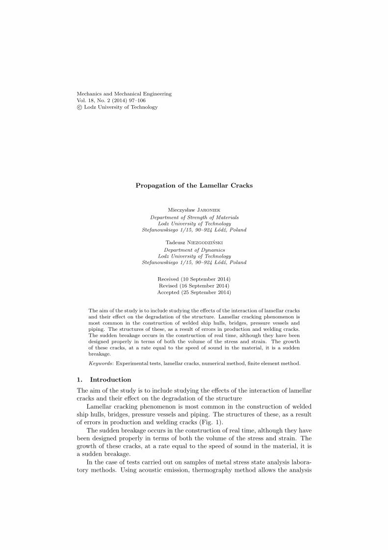
Lamellar cracking phenomenon is most common in the construction of weldedship hulls, bridges, pressure vessels and piping. The structures of these, as a resultof errors in production and welding cracks (Fig. 1).
The sudden breakage occurs in the construction of real time, although they havebeen designed properly in terms of both the volume of the stress and strain. Thegrowth of these cracks, at a rate equal to the speed of sound in the material, it isa sudden breakage.
In the case of tests carried out on samples of metal stress state analysis labora-tory methods. Using acoustic emission, thermography method allows the analysis
98 Jaroniek, M., Niezgodzinski, T.
of deformation, but does not reflect the view of the state of stress.Based on typical images metallographic steel sheets were admitted to study
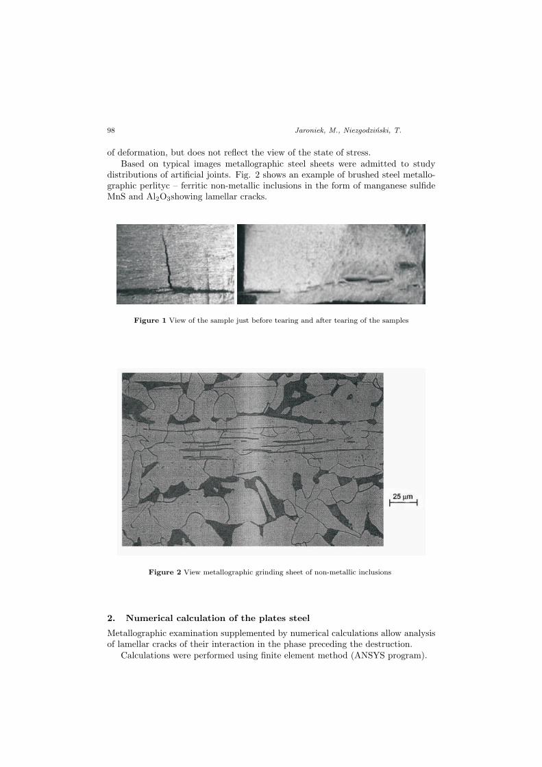
distributions of artificial joints. Fig. 2 shows an example of brushed steel metallo-graphic perlityc – ferritic non-metallic inclusions in the form of manganese sulfideMnS and Al2O3showing lamellar cracks.
Figure 1 View of the sample just before tearing and after tearing of the samples
Figure 2 View metallographic grinding sheet of non-metallic inclusions
2. Numerical calculation of the plates steel
Metallographic examination supplemented by numerical calculations allow analysisof lamellar cracks of their interaction in the phase preceding the destruction.
Calculations were performed using finite element method (ANSYS program).
Propagation of the Lamellar Cracks 99
For the analysis of stresses and deformations in part modeling sheet structureused flat triangular element A six PLANE2.
It was assumed:– Plane strain and the left edge of the restraint structure of the model,– Displacement of the right edge of the model with εx = 0.06 %.Analyzed models perlitic- ferritic steel structure with on metallic inclusions –
lamellar.Steel structure was modeled by adopting the following material data:– Ferrite: elastic material order;Young’s modulus in the range of elastic E = 204 GPaYoung’s modulus in the range of plastic Ep = 10 GPaPoisson’s ratio ν = 0.3yield strength Re = 150 MPatensile strength Rm = 300 MPa– Non–metallic inclusions:Young’s modulus E = 1 MPaPoisson’s ratio ν = 0.499In view of the slight value of Young’s modulus non–metallic inclusions was as-
sumed that these voids. The small size of the inclusions required to modeled steelstructure was the analysis of the micro. Constructed corresponding FEM model, inwhich the unit of length adopted micrometer [µm ].
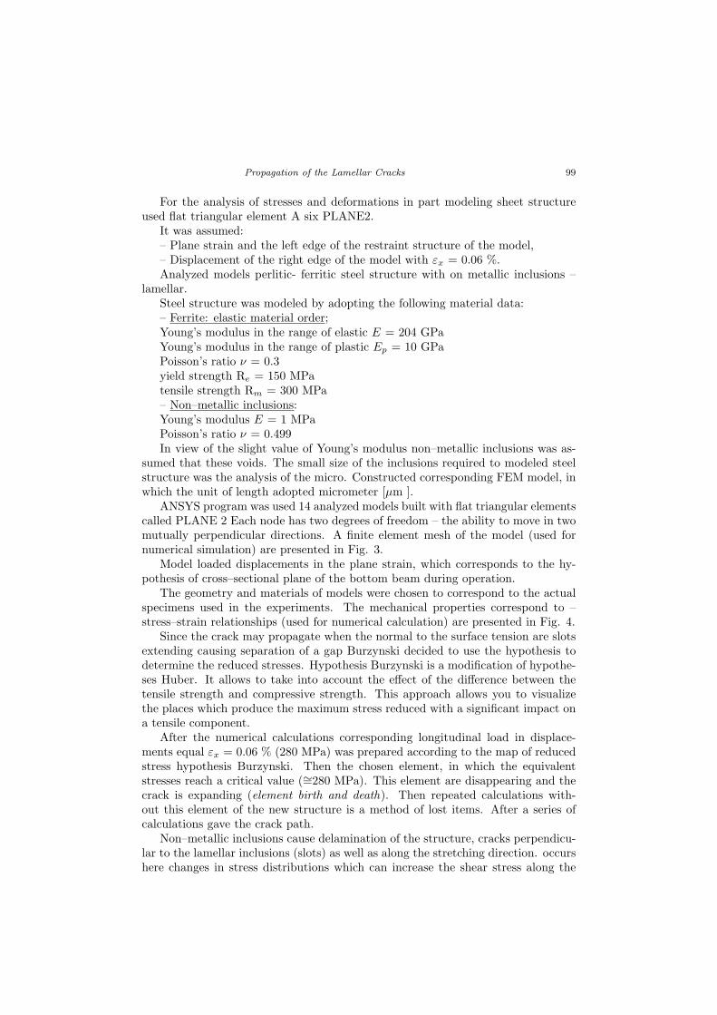
ANSYS program was used 14 analyzed models built with flat triangular elementscalled PLANE 2 Each node has two degrees of freedom – the ability to move in twomutually perpendicular directions. A finite element mesh of the model (used fornumerical simulation) are presented in Fig. 3.
Model loaded displacements in the plane strain, which corresponds to the hy-pothesis of cross–sectional plane of the bottom beam during operation.
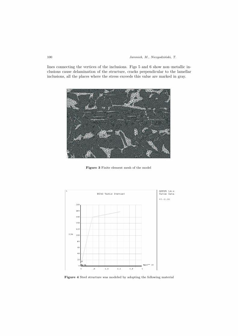
The geometry and materials of models were chosen to correspond to the actualspecimens used in the experiments. The mechanical properties correspond to –stress–strain relationships (used for numerical calculation) are presented in Fig. 4.
Since the crack may propagate when the normal to the surface tension are slotsextending causing separation of a gap Burzynski decided to use the hypothesis todetermine the reduced stresses. Hypothesis Burzynski is a modification of hypothe-ses Huber. It allows to take into account the effect of the difference between thetensile strength and compressive strength. This approach allows you to visualizethe places which produce the maximum stress reduced with a significant impact ona tensile component.
After the numerical calculations corresponding longitudinal load in displace-ments equal εx = 0.06 % (280 MPa) was prepared according to the map of reducedstress hypothesis Burzynski. Then the chosen element, in which the equivalentstresses reach a critical value (∼=280 MPa). This element are disappearing and thecrack is expanding (element birth and death). Then repeated calculations with-out this element of the new structure is a method of lost items. After a series ofcalculations gave the crack path.
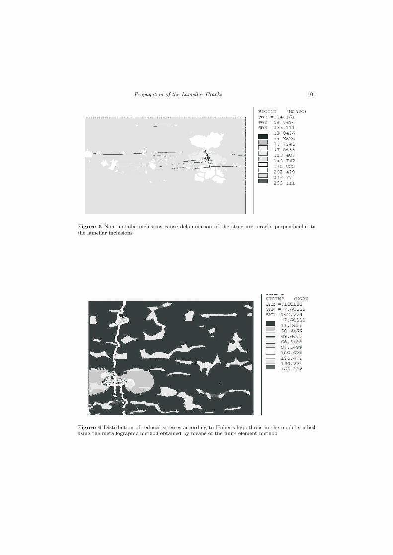
Non–metallic inclusions cause delamination of the structure, cracks perpendicu-lar to the lamellar inclusions (slots) as well as along the stretching direction. occurshere changes in stress distributions which can increase the shear stress along the
100 Jaroniek, M., Niezgodzinski, T.
lines connecting the vertices of the inclusions. Figs 5 and 6 show non–metallic in-clusions cause delamination of the structure, cracks perpendicular to the lamellarinclusions, all the places where the stress exceeds this value are marked in gray.
Figure 3 Finite element mesh of the model
Figure 4 Steel structure was modeled by adopting the following material
Propagation of the Lamellar Cracks 101
Figure 5 Non–metallic inclusions cause delamination of the structure, cracks perpendicular tothe lamellar inclusions
Figure 6 Distribution of reduced stresses according to Huber’s hypothesis in the model studiedusing the metallographic method obtained by means of the finite element method
102 Jaroniek, M., Niezgodzinski, T.
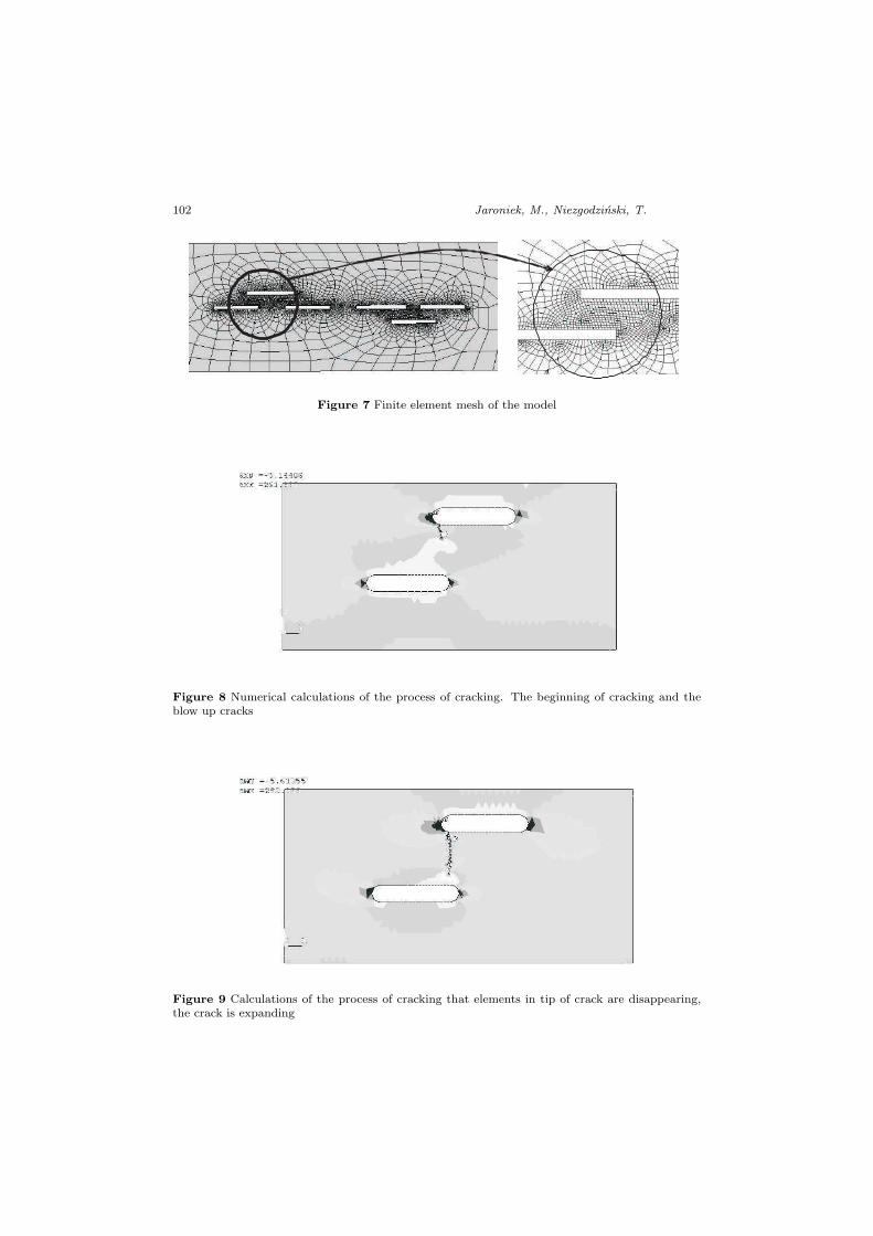
Figure 7 Finite element mesh of the model
Figure 8 Numerical calculations of the process of cracking. The beginning of cracking and theblow up cracks
Figure 9 Calculations of the process of cracking that elements in tip of crack are disappearing,the crack is expanding
Propagation of the Lamellar Cracks 103
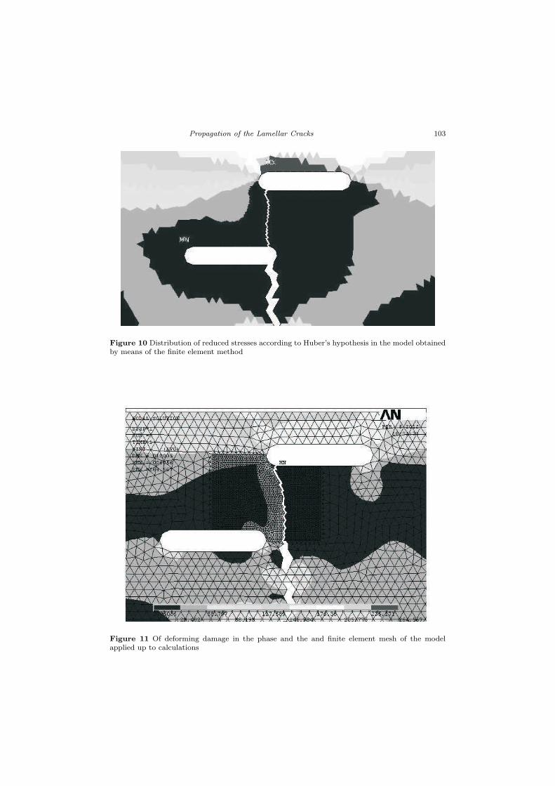
Figure 10 Distribution of reduced stresses according to Huber’s hypothesis in the model obtainedby means of the finite element method
Figure 11 Of deforming damage in the phase and the and finite element mesh of the modelapplied up to calculations
104 Jaroniek, M., Niezgodzinski, T.
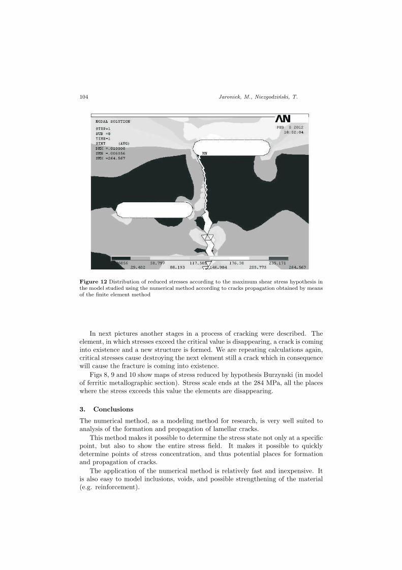
Figure 12 Distribution of reduced stresses according to the maximum shear stress hypothesis inthe model studied using the numerical method according to cracks propagation obtained by meansof the finite element method
In next pictures another stages in a process of cracking were described. Theelement, in which stresses exceed the critical value is disappearing, a crack is cominginto existence and a new structure is formed. We are repeating calculations again,critical stresses cause destroying the next element still a crack which in consequencewill cause the fracture is coming into existence.
Figs 8, 9 and 10 show maps of stress reduced by hypothesis Burzynski (in modelof ferritic metallographic section). Stress scale ends at the 284 MPa, all the placeswhere the stress exceeds this value the elements are disappearing.
3. Conclusions
The numerical method, as a modeling method for research, is very well suited toanalysis of the formation and propagation of lamellar cracks.
This method makes it possible to determine the stress state not only at a specificpoint, but also to show the entire stress field. It makes it possible to quicklydetermine points of stress concentration, and thus potential places for formationand propagation of cracks.
The application of the numerical method is relatively fast and inexpensive. Itis also easy to model inclusions, voids, and possible strengthening of the material(e.g. reinforcement).
Propagation of the Lamellar Cracks 105
This method, like every research method, should be used along with other meth-ods, e.g. experimental and numerical.
It is particularly effective to compare test results with results obtained usingthe finite element method; this is because, using this method, a numerical image ofreduced stresses according to the crack propagation.
The metallographic experimental method is very well suited to validation of anumerical model based on the finite element method.
This method makes it possible to determine distribution of reduced stressesaccording to Huber’s hypothesis in the model studied using the metallographicmethod obtained by means of the finite element method.
This work has been financed by funds from the National Science Centre. Projectno. 7151/B/T02/2011/40
References
[1] Dylag, Z., Jakubowicz, A. and Oros, Z.: Strength of Materials, (in Polish), WNT,1996.
[2] Blum, A. and Niezgodzinski, T.: Lamellar cracks, Publisher Institute for Sustain-able Technologies – Monographs, (in Polish), 2007.
[3] Neimitz, A.: Mechanics of fracture, PWN, (in Polish), 1998.
[4] Stupnicki, J.: Trends of experimental mechanics, Journ. of Theoterical and AppliedMechanics, Vol. 2, No 34, 207–233, 1965.
[5] Szymczyk, J. and Wozniak, C.: Continuum modelling of laminates with a slowlygraded microstructure, Archives of Mechanics, 58, 4–5, 445–458, 2006.
[6] User’s Guide ANSYS, Ansys, Inc., Huston, USA.
[7] Woniak, C.: Nonlinear Macro–Elastodynamics of Microperiodic Composites, Bull.Ac. Pol. Sci.: Tech. Sci., 41, 315–321, 1993.
[8] Zienkiewicz, O. C.: The Finite Element Method in Engineering Science, Mc Graw –Hill, 1971.


![A damage-based model for mixed-mode crack propagation in … · 2019. 12. 16. · propagation of interface cracks in bonded joints and delaminations in laminates (e.g. [9–17])](https://img.pdfslide.us/doc/110x75/61394fc1a4cdb41a985b9ef3/a-damage-based-model-for-mixed-mode-crack-propagation-in-2019-12-16-propagation.jpg)