Embed Size (px)
Citation preview
Proportional flow control valves
Wandfluh AG Tel. +41 33 672 72 72 E-mail: [email protected] Illustrations not obligatory Data sheet no.Postfach Fax +41 33 672 72 12 Internet: www.wandfluh.com Data subject to change 2.6-634E 1/3CH-3714 Frutigen Edition 17 01
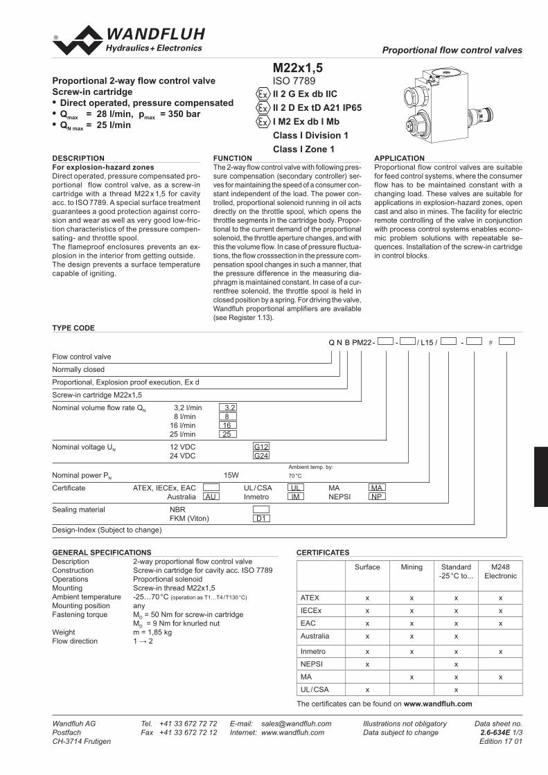
Proportional 2-way flow control valveScrew-in cartridge• Direct operated, pressure compensated• Qmax = 28 l/min, pmax = 350 bar• QN max = 25 l/min
DESCRIPTIONFor explosion-hazard zonesDirect operated, pressure compensated pro-portional flow control valve, as a screw-in cartridge with a thread M22 x 1,5 for cavity acc. to ISO 7789. A special surface treatment guarantees a good protection against corro-sion and wear as well as very good low-fric-tion characteristics of the pressure compen-sating- and throttle spool. The flameproof enclosures prevents an ex-plosion in the interior from getting outside. The design prevents a surface temperature capable of igniting.
FUNCTIONThe 2-way flow control valve with following pres-sure compensation (secondary controller) ser-ves for maintaining the speed of a consumer con-stant independent of the load. The power con-trolled, proportional solenoid running in oil acts directly on the throttle spool, which opens the throttle segments in the cartridge body. Propor-tional to the current demand of the proportional solenoid, the throttle aperture changes, and with this the volume flow. In case of pressure fluctua-tions, the flow crosssection in the pressure com-pensation spool changes in such a manner, that the pressure difference in the measuring dia-phragm is maintained constant. In case of a cur-rentfree solenoid, the throttle spool is held in closed position by a spring. For driving the valve, Wandfluh proportional amplifiers are available (see Register 1.13).
APPLICATIONProportional flow control valves are suitable for feed control systems, where the consumer flow has to be maintained constant with a changing load. These valves are suitable for applications in explosion-hazard zones, open cast and also in mines. The facility for electric remote controlling of the valve in conjunction with process control systems enables econo-mic problem solutions with repeatable se-quences. Installation of the screw-in cartridge in control blocks.
GENERAL SPECIFICATIONSDescription 2-way proportional flow control valveConstruction Screw-in cartridge for cavity acc. ISO 7789Operations Proportional solenoidMounting Screw-in thread M22x1,5Ambient temperature -25…70 °C (operation as T1…T4 / T130 °C)Mounting position anyFastening torque MD = 50 Nm for screw-in cartridge MD = 9 Nm for knurled nutWeight m = 1,85 kgFlow direction 1 → 2
TYPE CODE
Q N B PM22 - - / L15 / - #
Flow control valve
Normally closed
Proportional, Explosion proof execution, Ex d
Screw-in cartridge M22x1,5
Nominal volume flow rate QN 3,2 l/min 3,2 8 l/min 8 16 l/min 16 25 l/min 25
Nominal voltage UN 12 VDC G12 24 VDC G24 Ambient temp. by: Nominal power PN 15W 70 °C
Certificate ATEX, IECEx, EAC UL / CSA UL MA MA Australia AU Inmetro IM NEPSI NP
Sealing material NBR FKM (Viton) D1Design-Index (Subject to change)
M22x1,5ISO 7789II 2 G Ex db IICII 2 D Ex tD A21 IP65I M2 Ex db I MbClass I Division 1Class I Zone 1
CERTIFICATES
Surface Mining Standard-25 °C to...
M248 Electronic
ATEX x x x x
IECEx x x x x
EAC x x x x
Australia x x x
Inmetro x x x x
NEPSI x x
MA x x x
UL / CSA x x
The certificates can be found on www.wandfluh.com
Proportional flow control valves
Wandfluh AG Tel. +41 33 672 72 72 E-mail: [email protected] Illustrations not obligatory Data sheet no.Postfach Fax +41 33 672 72 12 Internet: www.wandfluh.com Data subject to change 2.6-634E 2/3CH-3714 Frutigen Edition 17 01
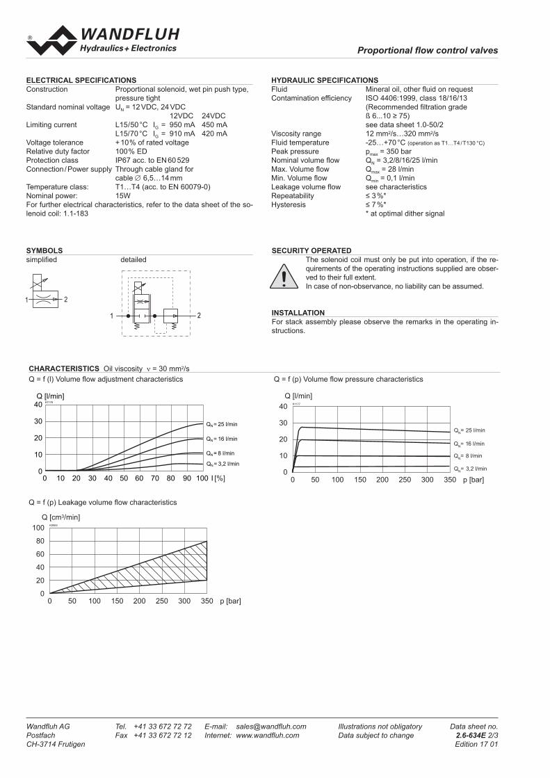
CHARACTERISTICS Oil viscosity ν= 30 mm2/sQ = f (l) Volume flow adjustment characteristics
Q = f (p) Leakage volume flow characteristics
Q = f (p) Volume flow pressure characteristics
HYDRAULIC SPECIFICATIONSFluid Mineral oil, other fluid on requestContamination efficiency ISO 4406:1999, class 18/16/13 (Recommended filtration grade ß 6...10 ≥ 75) see data sheet 1.0-50/2Viscosity range 12 mm2/s…320 mm2/sFluid temperature -25…+70 °C (operation as T1…T4 / T130 °C)Peak pressure pmax = 350 barNominal volume flow QN = 3,2/8/16/25 l/minMax. Volume flow Qmax = 28 l/minMin. Volume flow Qmin = 0,1 l/minLeakage volume flow see characteristicsRepeatability ≤ 3 %*Hysteresis ≤ 7 %* * at optimal dither signal
ELECTRICAL SPECIFICATIONSConstruction Proportional solenoid, wet pin push type, pressure tightStandard nominal voltage UN = 12 VDC, 24 VDC 12VDC 24VDCLimiting current L15/50 °C IG = 950 mA 450 mA L15/70 °C IG = 910 mA 420 mAVoltage tolerance + 10% of rated voltageRelative duty factor 100% EDProtection class IP67 acc. to EN 60 529Connection / Power supply Through cable gland for cable ∅ 6,5…14 mmTemperature class: T1…T4 (acc. to EN 60079-0)Nominal power: 15WFor further electrical characteristics, refer to the data sheet of the so-lenoid coil: 1.1-183
SYMBOLSsimplified detailed
SECURITY OPERATED The solenoid coil must only be put into operation, if the re-
quirements of the operating instructions supplied are obser-ved to their full extent.
In case of non-observance, no liability can be assumed.
INSTALLATIONFor stack assembly please observe the remarks in the operating in-structions.
K1176
QN = 25 l/min
QN = 16 l/min
QN = 8 l/min
QN = 3,2 l/min
Q [l/min]40
30
20
10
00 10 20 30 40 50 60 70 80 90 100 I [%]
40
30
20
10
00 50 100 150 200 250 300 350 p [bar]
K1177
Q [l/min]
QN= 25 l/min
QN= 16 l/min
QN= 3,2 l/min
QN= 8 l/min
100
80
60
40
20
00 50 100 150 200 250 300 350 p [bar]
K0965
Q [cm3/min]
s 30
M 22
x 1,5
22.5
42
64.5
93.3
38.6
10
60705040403020
80
95.6
134.2
1(P)
2(T)
1 2
1 2
Proportional flow control valves
Wandfluh AG Tel. +41 33 672 72 72 E-mail: [email protected] Illustrations not obligatory Data sheet no.Postfach Fax +41 33 672 72 12 Internet: www.wandfluh.com Data subject to change 2.6-634E 3/3CH-3714 Frutigen Edition 17 01
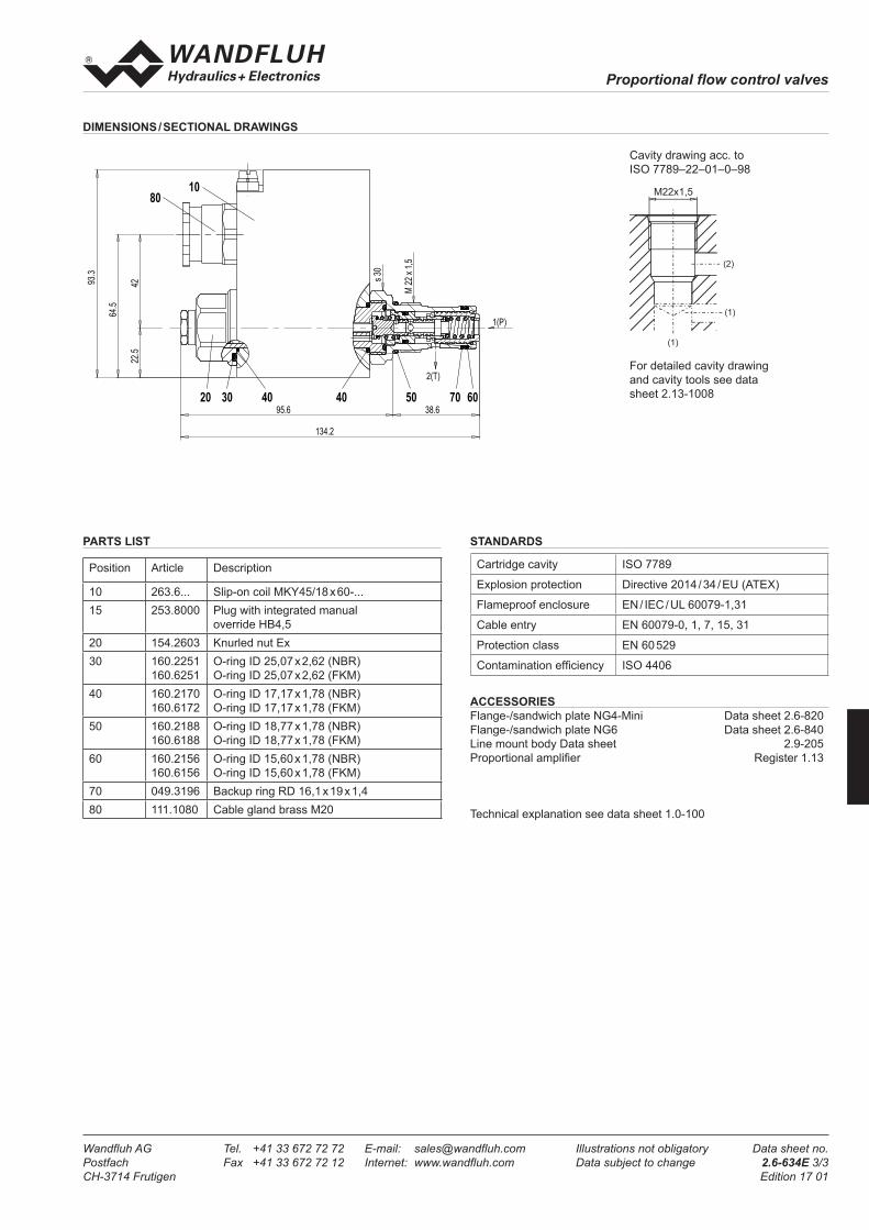
DIMENSIONS / SECTIONAL DRAWINGS
ACCESSORIESFlange-/sandwich plate NG4-Mini Data sheet 2.6-820Flange-/sandwich plate NG6 Data sheet 2.6-840Line mount body Data sheet 2.9-205Proportional amplifier Register 1.13
Technical explanation see data sheet 1.0-100
PARTS LIST
Position Article Description
10 263.6... Slip-on coil MKY45/18 x 60-...15 253.8000 Plug with integrated manual
override HB4,520 154.2603 Knurled nut Ex30 160.2251
160.6251O-ring ID 25,07 x 2,62 (NBR)O-ring ID 25,07 x 2,62 (FKM)
40 160.2170160.6172
O-ring ID 17,17 x 1,78 (NBR)O-ring ID 17,17 x 1,78 (FKM)
50 160.2188160.6188
O-ring ID 18,77 x 1,78 (NBR)O-ring ID 18,77 x 1,78 (FKM)
60 160.2156160.6156
O-ring ID 15,60 x 1,78 (NBR)O-ring ID 15,60 x 1,78 (FKM)
70 049.3196 Backup ring RD 16,1 x 19 x 1,480 111.1080 Cable gland brass M20
Cavity drawing acc. to ISO 7789–22–01–0–98
For detailed cavity drawingand cavity tools see datasheet 2.13-1008
(2)
(1)
M22x1,5
(1)
s 30
M 22
x 1,5
22.5
42
64.5
93.3
38.6
10
60705040403020
80
95.6
134.2
1(P)
2(T)
1 2
1 2STANDARDS
Cartridge cavity ISO 7789
Explosion protection Directive 2014 / 34 / EU (ATEX)
Flameproof enclosure EN / IEC / UL 60079-1,31
Cable entry EN 60079-0, 1, 7, 15, 31
Protection class EN 60 529
Contamination efficiency ISO 4406
![Spray paint booth · 2020. 2. 28. · Ga] IIC T5 Gb ATEX II 2(1) D Ex tb [ia Ga] IIIC T80°C Db HC2-SM-EX ATEX II 1/2 G Ex ia IIC T5 Ga/ Gb ATEX II 1/2 D Ex ia IIIC T80°C Da/Db IP66](https://img.pdfslide.us/doc/110x75/612e7b481ecc51586942d756/spray-paint-2020-2-28-ga-iic-t5-gb-atex-ii-21-d-ex-tb-ia-ga-iiic-t80c.jpg)

![Electromagnetic flowmeter ProcessMaster FEP630 ... · II 2 (1) G Ex db eb ib mb [ia Ga] IIC T6 T1 Gb II 2 (1) D Ex tb [ia Da] IIIC T80°C T medium Db DN3-100: II 2 (1) G Ex db eb](https://img.pdfslide.us/doc/110x75/5f0fde527e708231d4464930/electromagnetic-flowmeter-processmaster-fep630-ii-2-1-g-ex-db-eb-ib-mb-ia.jpg)

![Coriolis Mass Flowmeter - rockwin.com · ATEX approval Ex II (1) G ... ATEX approval Ex II 2(1) G Ex db eb [ia Ga] IIC T5 ATEX approval Ex II 2(1) G Ex db [ia Ga] IIC T6 ATEX rating](https://img.pdfslide.us/doc/110x75/5b3fe5ef7f8b9a4b3f8ca4f0/coriolis-mass-flowmeter-atex-approval-ex-ii-1-g-atex-approval-ex-ii.jpg)


![Type X & Ex px purge and pressurization system 6000 ...files.pepperl-fuchs.com/selector_files/navi/productInfo/edb/514685... · Ex db [ib pxb] IIIC T80 °C Db (-20 °C ≤ Ta ≤](https://img.pdfslide.us/doc/110x75/5bed6f5809d3f2da098b8cf8/type-x-ex-px-purge-and-pressurization-system-6000-filespepperl-fuchscomselectorfilesnaviproductinfoedb514685.jpg)


![ex.IECEx CML 15.0089X 1 - ppi-engineering.com · Ex tb [pxb] [ib] IIIC T135°C Db Ex db eb [ib] [pxb] IIC T4 Gb Ex tb [pxb] [ib] IIIC T135°C Db Ta = -40°C to +55°C Ta = -20°C](https://img.pdfslide.us/doc/110x75/5ca4610288c993fb118bff8e/exiecex-cml-150089x-1-ppi-ex-tb-pxb-ib-iiic-t135c-db-ex-db-eb-ib.jpg)