Embed Size (px)
Citation preview

Service Manual
DEALER: Keep this manual. The procedures in this manual MUST be performed by a qualified technician.
For more information regarding Invacare products, parts, and services,
please visit www.invacare.com
Pronto® SeriesM50™
M51™
M61™

RECOMMENDED TOOLS
Pronto® Series 2 Part No 1125075
� WARNINGA QUALIFIED TECHNICIAN MUST PERFORM ALL PROCEDURES IN THIS SERVICE MANUAL.
DEALERS AND QUALIFIED TECHNICIANS: DO NOT SERVICE OR OPERATE THIS EQUIPMENT WITHOUT FIRST READING AND UNDERSTANDING (1) THE OWNER’S OPERATOR AND MAINTENANCE MANUAL, (2) THE SERVICE MANUAL (IF APPLICABLE) AND (3) THE SEATING SYSTEM’S MANUAL (IF APPLICABLE). IF YOU ARE UNABLE TO UNDERSTAND THE WARNINGS, CAUTIONS AND INSTRUCTIONS, CONTACT INVACARE TECHNICAL SUPPORT BEFORE ATTEMPTING TO SERVICE OR OPERATE THIS EQUIPMENT. OTHERWISE, INJURY OR DAMAGE MAY RESULT.
RECOMMENDED TOOLSThe following tools are recommended for servicing this wheelchair:• Invacare Power Mobility Field Service Kit - p/n 1125222• 5mm ball head 10-inch t-handle allen wrench• Flat tip screwdriver• ½-inch deep socket and 3/8-inch ratchet• Small and Medium Phillips® screwdriver• Needle nose pliers• Wire cutters• Tie-wrap assortment• Dead blow hammer• ¼-inch to ½-inch wrenches
REFERENCE DOCUMENTS
DOCUMENT PART NUMBER
M50/51/61 Owner’s Manual 1125085
MK5™NX™Electronics Manual 1110532
Quad-Link Instruction Sheet (for assemblies after 4/6/06) 1134844
MK6i™Field Reference Guide 1141471
MK6i Service Manual 1143203
NOTE: Updated versions of this manual are available on www.invacare.com.

TABLE OF CONTENTS
TABLE OF CONTENTS
RECOMMENDED TOOLS .................................................................... 2REFERENCE DOCUMENTS ................................................................. 2SPECIAL NOTES ................................................................................ 6LABEL LOCATION ............................................................................ 8TYPICAL PRODUCT PARAMETERS .................................................... 9SECTION 1—GENERAL GUIDELINES ................................................. 11Accessories Information .........................................................................................................................11Batteries......................................................................................................................................................12Operation Information ............................................................................................................................13Tire Pressure .............................................................................................................................................14Grounding Instructions ...........................................................................................................................15Rain Test.....................................................................................................................................................15Repair or Service ......................................................................................................................................16Weight Training ........................................................................................................................................17Weight Limitation.....................................................................................................................................17
SECTION 2—EMI INFORMATION ..................................................... 18SECTION 3—SAFETY INSPECTION/TROUBLESHOOTING .................... 20
Safety Inspection Checklists ...................................................................................................................20Troubleshooting........................................................................................................................................21Checking Battery Charge Level.............................................................................................................30Field Load Test..........................................................................................................................................31Motor Testing............................................................................................................................................32
SECTION 4—WHEELCHAIR OPERATION ........................................... 33Turning the Power On/Off.....................................................................................................................33Using the Joystick to Drive the Wheelchair ......................................................................................34Adjusting the Speed .................................................................................................................................36Using the Horn..........................................................................................................................................37Elevating the Seat......................................................................................................................................38SPJ™Joystick Switches and Indicators .................................................................................................39SPJ+ and SPJ+ w/ACC Joystick Switches and Indicators .................................................................41
SECTION 5—ARMS ......................................................................... 44Removing/Installing Van Seat Arm........................................................................................................44Adjusting Van Seat Arm Width .............................................................................................................44Adjusting Van Seat Arm Angle ..............................................................................................................45Adjusting Van Seat Arm Height (Adjustable Height Arms Only)..................................................45Replacing Van Seat Armrest Assembly................................................................................................46Removing/Installing Flip Back Armrest ................................................................................................47Adjusting the Flip Back Armrest Height..............................................................................................48
SECTION 6—VAN SEAT ................................................................... 49Adjusting the Back Angle ........................................................................................................................49Adjusting the Headrest (Semi-Recline Only) .....................................................................................50Removing/Installing the Seat Assembly................................................................................................50Adjusting Seat Depth ...............................................................................................................................51Adjusting the Seat Height .......................................................................................................................53Adjusting Seat Position on Seat Base ...................................................................................................56Replacing the Seat Positioning Strap ....................................................................................................58
Part No 1125075 3 Pronto® Series

TABLE OF CONTENTS
TABLE OF CONTENTS
SECTION 7—ASBA SEAT ................................................................. 59Removing/Installing the Seat Assembly................................................................................................59Adjusting the Seat Height .......................................................................................................................60Removing/Installing the Seat Pan...........................................................................................................62Adjusting the Seat Width........................................................................................................................63Removing/Installing the Seat Frame......................................................................................................63Adjusting the Seat Frame Position........................................................................................................64Removing/Installing the Seat Positioning Strap ..................................................................................67Removing/Installing the Back Upholstery............................................................................................68Removing/Installing/Changing the Back Cane Height .......................................................................68Adjusting the Back Angle ........................................................................................................................72
SECTION 8—FRONT RIGGINGS/FOOTBOARD .................................... 74Installing/Removing Front Riggings .......................................................................................................74Adjusting Footrest Height ......................................................................................................................75Replacing Heel Loops ..............................................................................................................................76Raising/Lowering Elevating Front Riggings ..........................................................................................77Adjusting/Replacing Telescoping Front Rigging Supports................................................................77Removing/Installing the Footboard Assembly....................................................................................79Adjusting the Footboard Assembly ......................................................................................................80Checking the Clearance between the Front Rigging and Caster Wheel or Front Rigging andFront Shroud .............................................................................................................................................82
SECTION 9—WHEELS ....................................................................... 83Replacing the Front/Rear Casters.........................................................................................................83Adjusting Caster Assembly.....................................................................................................................83Removing/Installing the Front/Rear Caster Assemblies...................................................................84Removing/Installing the Front Headtube Assembly..........................................................................84Removing/Installing the Drive Wheel ..................................................................................................85Replacing the 2-Piece Wheel Rim and/or the Foam Filled or Pneumatic Tires.........................86
SECTION 10—SHROUDS AND FRAME .............................................. 88Removing/Installing the Top Shroud ....................................................................................................88Removing/Installing the Side Shrouds ..................................................................................................89Removing/Installing the Front Shroud .................................................................................................90Removing/Installing the Inner Shrouds ................................................................................................91Removing/Installing the Pivot Tube ......................................................................................................92Removing/Installing the SureStep Spring .............................................................................................94Removing/Installing the Walking Beam................................................................................................94Removing/Installing the Elevate Actuator ...........................................................................................95Removing/Installing the Actuator Switch Sensor ..............................................................................98
SECTION 11—BATTERIES ................................................................ 99Warnings For Handling and Replacing Batteries ...............................................................................99Using the Proper Batteries.................................................................................................................. 100Removing/Installing Batteries from/into Battery Tray................................................................... 100Connecting/Disconnecting Battery Cables ...................................................................................... 102Charging Batteries ................................................................................................................................. 105Battery Charger Operation................................................................................................................. 106Replacing the On-Board Battery Charger Fuse.............................................................................. 109Replacing the On-Board Battery Charger ....................................................................................... 110
Pronto® Series 4 Part No 1125075

TABLE OF CONTENTS
TABLE OF CONTENTS
SECTION 12—MOTORS .................................................................. 113Removing/Installing the Motor ........................................................................................................... 113Engaging/Disengaging Motor Release Lever .................................................................................... 115Removing/Installing the Motor Release Lever ................................................................................ 116Replacing Motor Brushes..................................................................................................................... 117Electro-Mechanical Parking Brake Testing....................................................................................... 119
SECTION 13—ELECTRONICS .......................................................... 121Removing/Installing the Joystick ......................................................................................................... 121Repositioning the Joystick Mounting Bracket ................................................................................. 122Disconnecting/Connecting the Joystick............................................................................................ 124Adjusting the Quad-Link Retractable Mount .................................................................................. 125Replacing the Controller ..................................................................................................................... 126Wire Routing.......................................................................................................................................... 128
SECTION 14—ACCESSORIES .......................................................... 129Installing/Removing the Crutch/Cane Holder................................................................................. 129Installing/Removing the Oxygen Holder .......................................................................................... 130Installing/Removing/Using the Walker Holder ............................................................................... 131
Part No 1125075 5 Pronto® Series

SPECIAL NOTES
SPECIAL NOTESSignal words are used in this manual and apply to hazards or unsafe practices which could result in personal injury or property damage. Refer to the table below for definitions of the signal words.
NOTICETHE INFORMATION CONTAINED IN THIS DOCUMENT IS SUBJECT TO CHANGE WITHOUT NOTICE.WHEELCHAIR USERAs a manufacturer of wheelchairs, Invacare endeavors to supply a wide variety of wheelchairs to meet many needs of the end user. However, final selection of the type of wheelchair to be used by an individual rests solely with the user and his/her healthcare professional capable of making such a selection.WHEELCHAIR TIE-DOWN RESTRAINTS AND SEAT RESTRAINTSWheelchair users should not be transported in vehicles of any kind while in wheelchairs. As of this date, the Department of Transportation has not approved any tie-down systems for transportation of a user while in a wheelchair, in a moving vehicle of any type.It is Invacare’s position that users of wheelchairs should be transferred into appropriate seating in vehicles for transportation and use be made of the restraints made available by the auto industry. Invacare cannot and does not recommend any wheelchair transportation systems.
� DANGERRisk of Death or Serious InjuryNot wearing your seat positioning strap could result in death or serious injury.ALWAYS wear your seat positioning strap. Your seat positioning strap helps reduce the possibility of a fall from the wheelchair. The seat positioning strap is a position-ing belt only. It is not designed for use as a safety device withstanding high stress loads such as auto or aircraft safety belts. If signs of wear appear, seat positioning strap MUST be replaced IMMEDIATELY.
SIGNAL WORD MEANING
DANGERDanger indicates an imminently hazardous situation which, if not avoided, will result in death or serious injury.
WARNINGWarning indicates a potentially hazardous situation which, if not avoided, could result in death or serious injury.
CAUTIONCaution indicates a potentially hazardous situation which, if not avoided, may result in property damage.
Pronto® Series 6 Part No 1125075
SPECIAL NOTES
� WARNINGThe drive behavior initially experienced by the user may be different from other chairs previously used. This power wheelchair has Invacare’s SureStep® technology, a feature that provides the chair with optimum traction and stability when driving forward over transitions and thresholds of up to 2-inches.The following warnings apply specifically to the SureStep Feature.• DO NOT use on inclines greater than 9°.To determine and establish your particular safety limits, practice use of this product on various sloping surfaces in the presence of a qualified healthcare provider before attempting active use of this wheelchair. Other general warnings listed within this document also apply.
Part No 1125075 7 Pronto® Series

LABEL LOCATION
Pronto® Series 8 Part No 1125075
LABEL LOCATIONThe serial number label is located inside of the front frame. The top shroud and front battery need to be removed to view the label.M50/M51 Wheelchairs
M61 Wheelchairs

SPECIFICATIONS
SPECIFICATIONSMEDIUM
BACKSEMI-RECLINE
BACKOFFICE STYLE, SEMI-RECLINE
BACK
ASBA
SEAT WIDTH RANGE: 18 inches 16 inches
18 inches
20 inches
18 inches 16 - 20 inches
SEAT DEPTH: 16 - 18 inches
16 - 18 inches 18 - 20 inches
16 - 18 inches 16 - 20 inches
BACK HEIGHT: 16½ inches 19 inches 23½ inches (w/ headrest)18¾ inches
(w/o headrest)
16 - 20 inches
BACK ANGLE RANGE: 95° to 100° in 5°
increments
90 to 114° 90 to 115° 80° to 100°in 5° increments
UPHOLSTERY: Light Grey Vinyl
Light Grey Vinyl, Grey Cloth, Tan Vinyl
Charcoal Grey Vinyl Black Nylon Back with Seat
Pan
SEAT-TO-FLOORWITH FOOTBOARD (M50/M51):
WITH FRONT RIGGINGS (M50/M51):
WITH ELEVATING SEAT (M61):
20 to 24 inches
22 to 24 inches
21-23 inches + up to 5 inches of Elevate
19 to 23 inches
19-23 inches
19 to 21 inches + up to 5 inches of
Elevate
17-21 inches
19-21 inches
17 to 19 inches + up to 5 inches
of Elevate
OVERALL WIDTH: 24 inches (Without Joystick)
OVERALL HEIGHT: 35 to 43¾ inches 41½ inches
OVERALL LENGTH: 34 inches (With Footboard Folded)39½ inches (With Footboard Extended)
OPERATING TEMPER-ATURE
122 F (50 C) Maximum to -13 F (-25 C) Minimum
STORAGE TEMPERA-TURE
149 F (65 C) Maximum to -58 F (-40 C) Minimum
DRIVE WHEELS/TIRES: 10 x 3-inch (Flat Free inserts)
CASTER: 6 x 2-inch Front/Rear w/Precision Sealed Bearings
FOOTRESTS/LEGRESTS:
Flip Up, Depth and Height Adjustable, Footboard, Swingaway Front Rigging, Elevating Legrest
*WEIGHTW/O BATTERIES:W/BATTERIES (U1):
145 to 170 lbs192 to 217 lbs
Part No 1125075 9 Pronto® Series

SPECIFICATIONS
*NOTE: Includes seating systems and accessories.
**NOTE: Values for range are calculated for maximum chair weight rating using largest batteries applicable (U1), per test procedures described in ANSI/RESNA WC/VOL2-1998 Section 4 and meet federal reimbursement requirements for this product. While considered typical, they are derived based on certain ideal conditions. Variances in battery condition, user weight, usage pattern or overall terrain conditions will result in actual values for range that differ from these stated values. Users should become accustomed to how their unique conditions impact their individual results. Users should become familiar with the battery discharge indicator on the joystick to determine the range of their wheelchair. Refer to Battery Charger Operation on page 106 for more information about the battery discharge indicator.
SHIPPINGBASE W/O BATTERIES:BASE WITH BATTERIES:MEDIUM BACK:SEMI-RECLINE:OFFICE STYLE:ASBA (20 X 20 X 20):
107 lbs154 lbs40 lbs64 lbs44 lbs48 lbs
ARMRESTS: Adjustable Width, Angle, Heights and Depth
BATTERIES: U1 - Quantity 2
WEIGHT LIMITATION: 300 lbs
PERFORMANCESPEED:TURNING RADIUS:**RANGE (VARIABLE):
0 to 4.3 m.p.h.19½ inches
up to 12 miles
MEDIUM BACK
SEMI-RECLINE BACK
OFFICE STYLE, SEMI-RECLINE
BACK
ASBA
Pronto® Series 10 Part No 1125075

SECTION 1—GENERAL GUIDELINES
SECTION 1—GENERAL GUIDELINES
� WARNINGSECTION 1 - GENERAL GUIDELINES contains important information for the safe operation and use of this product.
� DANGERRisk of Death, Serious Injury or DamageImproper use of this product may cause injury or damageIf you are unable to understand the warnings, cautions or instructions, contact a health care professional or dealer before attempting to use this equipment.DO NOT use this product or any available optional equipment without first completely reading and understanding these instructions and any additional instructional material such as user manual, service manuals or instruction sheets supplied with this product or optional equipment.
Accessories Information
� WARNINGRisk of Serious Injury or DamageUse of non-Invacare accessories may result in serious injury or damage.Invacare products are specifically designed and manufactured for use in conjunction with Invacare accessories. Accessories designed by other manufacturers have not been tested by Invacare and are not recommended for use with Invacare products.DO NOT use non-Invacare accessories.To obtain Invacare accessories, contact Invacare by phone or at www.invacare.com.
� WARNINGExtreme care should be exercised when using oxygen in close proximity to electric circuits and other combustible materials. Contact your oxygen supplier for instruction in the use of oxygen.
Part No 1125075 11 Pronto® Series

SECTION 1—GENERAL GUIDELINES
Batteries
� WARNINGThe warranty and performance specifications contained in this manual are based on the use of deep cycle gel cell or sealed lead acid batteries. Invacare strongly recommends their use as the power source for this unit.Carefully read battery/battery charger information prior to installing, servicing or operating your wheelchair.
Charging Batteries
� DANGERWhen using an extension cord, use only a three wire extension cord having at least 16 AWG (American Wire Gauge) wire and the same or higher electrical rating as the device being connected. Use of improper extension cord could result in risk of fire and electric shock. Three prong to two prong adapters should not be used. Use of three prong adapters can result in improper grounding and present a shock hazard to the user.
� WARNINGNEVER attempt to recharge the batteries by attaching cables directly to the battery terminals.DO NOT attempt to recharge the batteries and operate the wheelchair at the same time.DO NOT operate wheelchair with extension cord attached to the AC cable.DO NOT attempt to recharge the batteries when the wheelchair has been exposed to any type of moisture.DO NOT attempt to recharge the batteries when the wheelchair is outside.DO NOT sit in the wheelchair while charging the batteries.DO NOT attempt to recharge batteries using both the on-board battery charger and an independent battery charger (plugged into the joystick charger port) at the same time. Doing so will reduce the life of the batteries.Read and carefully follow the manufacturer’s instructions for each charger (supplied or purchased). If charging instructions are not supplied, consult a qualified technician for proper procedures.Ensure the pins of the extension cord plug are the same number, size, and shape as those on the charger.
DO NOT under any circumstances cut or remove the round grounding plug from the charger AC cable plug or the extension cord plug.
Pronto® Series 12 Part No 1125075

SECTION 1—GENERAL GUIDELINES
Operation Information
� WARNINGRisk of Serious Injury or DamageMoving the seating system from the factory setting may reduce driver control, wheelchair stability, traction and increase caster wear resulting in serious injury or damage.Move the seating system ONLY when necessary to fit the wheelchair to the user.If the seating system must be moved, ALWAYS inspect the wheelchair to ensure the front rigging DOES NOT interfere with the front casters.If the seating system must be moved, ALWAYS inspect to ensure the wheelchair DOES NOT easily tip forward or backward.
� DANGERRisk of Death, Serious Injury, or DamageContinued use of the wheelchair that is not set to the correct specifications may cause erratic behavior of the wheelchair resulting in death, serious injury, or damage.Performance adjustments should only be made by professionals of the healthcare field or persons fully conversant with this process and the driver's capabilities. After the wheelchair has been set up/adjusted, check to make sure that the wheelchair performs to the specifications entered during the set up procedure. If the wheelchair does not perform to specifications, turn the wheelchair Off immediately and reenter set up specifications. Contact Invacare, if wheelchair still does not perform to correct specifications.Electric shock can cause death or serious injuryTo avoid electric shock, inspect plug and cord for cuts and/or frayed wires. Replace cut cords or frayed wires immediately.
� DANGERRisk of Death or Serious InjuryTraveling on inclines with wet, slippery, icy or oily surfaces could cause loss of traction resulting in death or serious injury.DO NOT use on inclines with wet, slippery, icy or oily surfaces. This may include certain painted or otherwise treated wood surfaces.
� WARNINGRisk of Minor to Serious InjuryPinch points can cause minor to serious injury.Be mindful of potential pinch points and use caution when using this product.
Part No 1125075 13 Pronto® Series

SECTION 1—GENERAL GUIDELINES
� WARNINGALWAYS shift your weight in the direction you are turning. DO NOT shift your weight in the opposite direction of the turn. Shifting your weight in the opposite direction of the turn may cause the inside drive wheel to lose traction and the wheelchair to tip over.DO NOT shift your weight or sitting position toward the direction you are reaching as the wheelchair may tip over.DO NOT engage or disengage the motor release levers until the power is in the Off position.DO NOT climb, go up or down ramps or traverse slopes greater than 9°.DO NOT attempt to drive over curbs or obstacles. Doing so may cause your wheelchair to turn over and cause bodily harm or damage to the chair.DO NOT leave the power button in the On position when entering or exiting your wheelchair.DO NOT stand on the frame of the wheelchair.DO NOT stand on the flip-up footboard, otherwise damage may occur. When getting in or out of the wheelchair, make sure that the flip-up footboard is in the upward position.Before performing any maintenance, adjustment or service verify that On/Off switch on the joystick is in the Off position.Avoid storing or using the wheelchair near open flame or combustible products. Serious injury or damage to property may result.ALWAYS keep hands and fingers clear of moving parts to avoid injury.NEVER leave an unoccupied wheelchair on an incline.DO NOT attempt to lift the wheelchair by any removable (detachable) parts. Lifting by means of any removable (detachable) parts of the wheelchair may result in injury to the user or damage to the wheelchair.Make sure the detent balls of the quick-release pin are fully released beyond the outer edge of the tube before operating the wheelchair. Otherwise, injury and/or damage may result.
Keep detent balls clean.
Tire Pressure
� WARNINGDO NOT release wheelchair from service unless it has the proper tire pressure (P.S.I.). DO NOT overinflate the tires. Failure to follow these recommendations may cause the tire to explode and cause bodily harm. The recommended tire pressure is listed on the side wall of the tire.
Pronto® Series 14 Part No 1125075

SECTION 1—GENERAL GUIDELINES
Grounding Instructions
� WARNINGDO NOT, under any circumstances, cut or remove the round grounding prong from any plug used with or for Invacare products. Some devices are equipped with three-prong (grounding) plugs for protection against possible shock hazards and fire. Where a two-prong wall receptacle is encountered, it is the personal responsibility and obligation of the customer to contact a qualified electrician and have the two-prong receptacle replaced with a properly grounded three-prong wall receptacle in accordance with the National Electrical Code. If you must use an extension cord, use only a three-wire extension cord having the same or higher electrical rating as the device being connected. In addition, Invacare has placed RED/ORANGE warning tags on some equipment. DO NOT remove these tags.
Rain Test
� CAUTIONRisk of DamageOperating the wheelchair in rain or dampness may cause the wheelchair to malfunction electrically and mechanically; may cause the wheelchair to prematurely rust or may damage the upholstery.DO NOT leave wheelchair in a rain storm of any kind.DO NOT use wheelchair in a shower.DO NOT leave wheelchair in a damp area for any length of time.Check to ensure that the battery covers are secured in place, joystick boot is NOT torn or cracked where water can enter and that all electrical connections are secure at all times. DO NOT use if the joystick boot is torn or cracked. If the joystick boot becomes torn or cracked, replace IMMEDIATELY.
NOTE: Invacare has tested its power wheelchairs in accordance with ISO 7176 “Rain Test.” This provides the end user or his/her assistant sufficient time to remove his/her power wheelchair from a rain storm and retain wheelchair operation.
Part No 1125075 15 Pronto® Series

SECTION 1—GENERAL GUIDELINES
Repair or Service
� DANGERRisk of Death, Serious Injury or DamageUse of incorrect or improper replacement (service) parts may cause death, serious injury, or damage.Replacement parts MUST match original Invacare parts.ALWAYS provide the wheelchair serial number to assist in ordering the correct replacement parts.Corroded electrical components due to water, liquid exposure, or incontinent users can result in death, serious injury, or damage.Minimize exposure of electrical components to water and/or liquids. Electrical components damaged by corrosion MUST be replaced immediately.Wheelchairs that are used by incontinent users and/or are frequently exposed to water/liquids may require replacement of electrical components more frequently.
� DANGERRisk of Death, Serious Injury, or DamageMissing attaching hardware could cause instability resulting in death, serious injury or damage.Ensure all attaching hardware is present and tightened securely.
� WARNINGRisk of Serious Injury or DamageAttaching hardware that is loosely secured could cause loss of stability resulting in serious injury or damageAfter ANY adjustments, repair or service and before use, make sure that all attaching hardware is tightened securely.
� WARNINGRisk of Serious Injury or Damage Improperly connecting the motor leads to the controller may cause injury or damage.WHEELCHAIRS WITH G-TRAC: Crossing the motor leads (for example: connecting the left motor lead into the right motor connector on the controller) may result in unintended movement.DO NOT cross the motor leads when connecting the motors to the controller - otherwise injury or damage may occur.
Pronto® Series 16 Part No 1125075

SECTION 1—GENERAL GUIDELINES
� WARNINGSet-up of the Electronic Control Unit is to be performed only by a qualified technician. The final adjustments of the controller may affect other activities of the wheelchair. Damage to the equipment could occur if improperly set-up or adjusted.
Weight Training
� WARNINGInvacare does not recommend the use of its wheelchairs as a weight training apparatus. Invacare wheelchairs have not been designed or tested as a seat for any kind of weight training. If occupant uses said wheelchair as a weight training apparatus, Invacare shall not be liable for bodily injury and the warranty is void.
Weight Limitation
� WARNINGThe M50, M51 and M61 wheelchairs with SureStep have a weight limitation of 300 lbs.
Part No 1125075 17 Pronto® Series

SECTION 2—EMI INFORMATION
SECTION 2—EMI INFORMATION
� WARNINGCAUTION: IT IS VERY IMPORTANT THAT YOU READ THIS INFORMATION REGARDING THE POSSIBLE EFFECTS OF ELECTROMAGNETIC INTERFERENCE ON YOUR POWERED WHEELCHAIR.Electromagnetic Interference (EMI) From Radio Wave Sources Powered wheelchairs and motorized scooters (in this text, both will be referred to as powered wheelchairs) may be susceptible to electromagnetic interference (EMI), which is interfering electromagnetic energy (EM) emitted from sources such as radio stations, TV stations, amateur radio (HAM) transmitters, two way radios, and cellular phones. The interference (from radio wave sources) can cause the powered wheelchair to release its brakes, move by itself, or move in unintended directions. It can also permanently damage the powered wheelchair's control system. The intensity of the interfering EM energy can be measured in volts per meter (V/m). Each powered wheelchair can resist EMI up to a certain intensity. This is called its "immunity level." The higher the immunity level, the greater the protection. At this time, current technology is capable of achieving at least a 20 V/m immunity level, which would provide useful protection from the more common sources of radiated EMI.There are a number of sources of relatively intense electromagnetic fields in the everyday environment. Some of these sources are obvious and easy to avoid. Others are not apparent and exposure is unavoidable. However, we believe that by following the warnings listed below, your risk to EMI will be minimized. The sources of radiated EMI can be broadly classified into three types:1) Hand-held Portable transceivers (transmitters-receivers with the antenna
mounted directly on the transmitting unit. Examples include: citizens band (CB) radios, "walkie talkie", security, fire and police transceivers, cellular telephones, and other personal communication devices).
NOTE: Some cellular telephones and similar devices transmit signals while they are ON, even when not being used.2) Medium-range mobile transceivers, such as those used in police cars, fire trucks,
ambulances and taxis. These usually have the antenna mounted on the outside of the vehicle; and
3) Long-range transmitters and transceivers, such as commercial broadcast transmitters (radio and TV broadcast antenna towers) and amateur (HAM) radios.
NOTE: Other types of hand-held devices, such as cordless phones, laptop computers, AM/FM radios, TV sets, CD players, cassette players, and small appliances, such as elec-tric shavers and hair dryers, so far as we know, are not likely to cause EMI problems to your powered wheelchair.
Pronto® Series 18 Part No 1125075

SECTION 2—EMI INFORMATION
� WARNINGPowered Wheelchair Electromagnetic Interference (EMI)Because EM energy rapidly becomes more intense as one moves closer to the transmitting antenna (source), the EM fields from hand-held radio wave sources (transceivers) are of special concern. It is possible to unintentionally bring high levels of EM energy very close to the powered wheelchair's control system while using these devices. This can affect powered wheelchair movement and braking. Therefore, the warnings listed below are recommended to prevent possible interference with the control system of the powered wheelchair.Electromagnetic interference (EMI) from sources such as radio and TV stations, amateur radio (HAM) transmitters, two-way radios, and cellular phones can affect powered wheelchairs and motorized scooters. FOLLOWING THE WARNINGS LISTED BELOW SHOULD REDUCE THE CHANCE OF UNINTENDED BRAKE RELEASE OR POWERED WHEELCHAIR MOVEMENT WHICH COULD RESULT IN SERIOUS INJURY.1) Do not operate hand-held transceivers (transmitters receivers), such as citizens
band (CB) radios, or turn ON personal communication devices, such as cellular phones, while the powered wheelchair is turned ON;
2) Be aware of nearby transmitters, such as radio or TV stations, and try to avoid coming close to them;
3) If unintended movement or brake release occurs, turn the powered wheelchair OFF as soon as it is safe;
4) Be aware that adding accessories or components, or modifying the powered wheelchair, may make it more susceptible to EMI (NOTE: There is no easy way to evaluate their effect on the overall immunity of the powered wheelchair); and
5) Report all incidents of unintended movement or brake release to the powered wheelchair manufacturer, and note whether there is a source of EMI nearby.
Important Information
1) 20 volts per meter (V/m) is a generally achievable and useful immunity level against EMI (as of May 1994) (the higher the level, the greater the protection);
2) This device has been tested to a radiated immunity level of 20 volts per meter.3) The immunity level of the product is unknown.Modification of any kind to the electronics of this wheelchair as manufactured by Invacare may adversely affect the EMI immunity levels.
Part No 1125075 19 Pronto® Series

SECTION 3—SAFETY INSPECTION/TROUBLESHOOTING
SECTION 3—SAFETY INSPECTION/TROUBLESHOOTING
Safety Inspection ChecklistsInitial adjustments should be made to suit the end user’s personal body structure, needs, and preferences. After initial setup, perform these procedures every time the product is serviced.
All Wheelchairs
CAUTIONAs with any vehicle, the wheels and tires should be checked periodically for cracks and wear, and should be replaced.
❑ Ensure that the wheelchair rolls straight (no excessive drag or pull to one side).❑ Ensure that the arms are secure but easy to release and adjustment levers engage
properly.❑ Ensure that adjustable height arms operate and lock securely.❑ Ensure armrest pads sit flush against arm.❑ Ensure seat is secured to wheelchair frame.❑ Ensure seat release latch is functional. Replace if necessary.❑ Clean upholstery and armrests.❑ Ensure no excessive side movement or binding occurs when drive wheels are lifted
and spun when disengaged (freewheeling).❑ Inspect caster assembly has proper tension when caster is spun. Caster should come
to a gradual stop.❑ Loosen/tighten caster locknut if wheel wobbles noticeably or binds to a stop.❑ Ensure casters are free of debris.❑ Ensure all caster/wheel/fork/headtube fasteners are secure.❑ Inspect tires for flat spots and wear.❑ Ensure all fasteners on clothing guards are secure.❑ Seat and/or back upholstery have no rips and do not sag. Replace if necessary.❑ Inspect seat positioning strap for any signs of wear. Ensure buckle latches. Verify
hardware that attaches strap to frame is secure and undamaged. Replace if necessary.
❑ Ensure wheel mounting nuts are secure on drive wheels.
❑ Check pneumatic tires for proper inflation.
❑ Inspect motor brushes and gearbox coupling.
Pronto® Series 20 Part No 1125075

SECTION 3—SAFETY INSPECTION/TROUBLESHOOTING
❑ Ensure seat is secured to wheelchair frame.❑ Ensure seat release latch is not worn and is functional. Replace if necessary.❑ Ensure arm pivot points are not worn and/or loose. Replace if necessary.❑ Inspect for any loose hardware on the wheelchair.❑ Inspect charger AC power cord for damage. Replace if necessary.❑ Check that all labels are present and legible. Replace if necessary.❑ Inspect electrical components for signs of corrosion. Replace if corroded or damaged.
Additional Requirements for M61 Wheelchairs
❑ Make sure elevate operates smoothly and properly.
❑ Make sure elevate systems drive with reduced speed when seat is in elevated position.
TroubleshootingNOTE: For additional troubleshooting information and explanation of error codes, refer to the individual electronics manual supplied with each wheelchair.
Wheels
About Joystick Diagnostics
The joystick information gauge and the service indicator give indications of the type of fault or error detected by the control module. When a fault is detected, the wheelchair may stop and not drive. The LEDs on the information gauge may flash in a particular pattern or the service indicator light will flash. The number or type of flashes indicates the nature of the error. If multiple errors are found, only the first error encountered by the control module will be displayed.
WH
EELC
HA
IR V
EER
SLE
FT/R
IGH
T
SLU
GG
ISH
TU
RN
/PE
RFO
RM
AN
CE
CA
STER
SFL
UT
TER
SQU
EAK
S A
ND
RA
TT
LES
LOO
SEN
ESS
IN W
HEE
LCH
AIR
WH
EELC
HA
IR 3
WH
EELS
SOLUTIONS
X X X If pneumatic, check tires for correct and equal pressure.
X X X X Check for loose stem nuts/bolts.
X X Check that casters contact ground at the same time.
Part No 1125075 21 Pronto® Series

SECTION 3—SAFETY INSPECTION/TROUBLESHOOTING
SPJ+ Information Gauge Display Diagnostics
DISPLAY DESCRIPTION DEFINITION COMMENTS
All LEDs are off. Power is off.
All LEDs are on. Power is on. Fewer than three LEDs on implies reduced battery charge.
Left RED LED is flashing. Battery charge is low. The batteries should be charged as soon as possi-ble.
Left to Right “chase” alter-nating with steady display.
Joystick is in program-ming, inhibit and/or charg-ing mode.
The steady LEDs indicate the current state of the battery charge.
All LEDs are flashing slowly. Joystick has detected Out-of-Neutral-at-Power-Up mode.
Release the joystick back to Neutral.
Information Gauge Display
Pronto® Series 22 Part No 1125075

SECTION 3—SAFETY INSPECTION/TROUBLESHOOTING
SPJ Information Gauge Display Diagnostics
DISPLAY DESCRIPTION DEFINITION COMMENTS
All three LEDs are Off. Power is Off.
All three LEDs are On. Power is On. Fewer than three LEDs On implies reduced battery charge.
RED LED is flashing. Battery charge is low. The batteries should be charged as soon as possible.
Left to Right “chase” alternating with steady display.
Joystick is in programming, inhibit and/or charging mode.
The steady LEDs indicate the current state of the battery charge.
GREEN LED is flashing. Joystick is in Speed Limit mode.
The current state of battery charge will be displayed at the same time.
All LEDs are flashing slowly. Joystick has detected Out-of-Neutral-at-Power-Up mode.
Release the joystick back to Neutral.
All LEDs are flashing quickly.
Joystick has detected a fault.
Joystick uses Flash codes to indicate faults.
INVACARE
INVACARE
INVACARE
INVACARE
INVACARE
INVACARE
INVACARE
Part No 1125075 23 Pronto® Series

SECTION 3—SAFETY INSPECTION/TROUBLESHOOTING
Diagnostic CodesN
UM
BER
OF
FLA
SHES
DIA
GN
OST
ICS
CO
DE
ERR
OR
CO
DE
DES
CR
IPT
ION
SUB
CO
DE*
DET
AIL
S O
F ER
RO
R C
OD
E
POSS
IBLE
SO
LUT
ION
1 E 01 User Fault 00 Stall Timeout or user error. Release joystick to neutral and try again.
2 E02 Battery Fault 00 Recharge batteries or replace. Check the batteries and cable. Try charg-ing the batteries. Batteries may require
replacing.
3 E03 Left Motor Fault 00 Left Motor Short Circuit Check the left motor, connections and motor cable.01 Left Motor Open Circuit
02 Left Motor Connection Fault B-
03 Motor Terminal Connected to B+
04 Left Motor Voltage Fault
05 Left Motor Bridge Fault
06 Too Many Hardware Current Limit Events
07 Current Offset Out of Range
08 Hardware Current Limit Fault
4 E04 Right Motor Fault 00 Right Motor Short Circuit Check the right motor, connections and motor cable.01 Right Motor Open Circuit
02 Right Motor Connection Fault B-
03 Motor Terminal Connected to B+
04 Right Motor Voltage Fault
05 Right Motor Bridge Fault
06 Too Many Hardware Cur-rent Limit Events
07 Current Offset Out of Range
08 Hardware Current Limit Fault
Pronto® Series 24 Part No 1125075

SECTION 3—SAFETY INSPECTION/TROUBLESHOOTING
5 E05 Left Park Brake Fault
00 Left Park Brake Drive-Time Test Failed
Check the left park brake connections and cable.
01 Left Park Brake Output Enabled When Wheelchair
Idle
02 Left Park Brake Output Did not Enable When Entering
Drive Mode
03 Left Park Brake fault during power-up testing
04 Left park brake feedback low during drive (park brake
short)
6 E06 Right Park Brake Fault
00 Right Park Brake Drive-Time Test Failed
Check the right park brake connections and cable.
01 Right Park Brake Output Enabled When Wheelchair
Idle
02 Right Park Brake Output Did not Enable When Entering
Drive Mode
03 Right Park Brake fault during power-up testing
04 Right park brake feedback low during drive (park brake
short)
7 E07 Remote Fault 00 Local SR Fault (CPU, EEPROM, etc.)
Check the communications bus, connec-tions and wiring. Replace the remote.
01 Joystick fault at the remote
02 Speed pot fault at the remote
NU
MBE
R O
F FL
ASH
ES
DIA
GN
OST
ICS
CO
DE
ERR
OR
CO
DE
DES
CR
IPT
ION
SUB
CO
DE*
DET
AIL
S O
F ER
RO
R C
OD
E
POSS
IBLE
SO
LUT
ION
Part No 1125075 25 Pronto® Series

SECTION 3—SAFETY INSPECTION/TROUBLESHOOTING
Motor/Gearbox/Brake
8 E08 Controller Fault 00 Controller fault Check connections and wiring. Replace power module.01 RAM fault
02 ROM fault
03 CPU fault
04 EEPROM fault
05 Watchdog fault
06 Stack fault
07 Software fault
08 Power-up testing fault
09 Relay fault or precharge fault
10 Bridge fault or disable all fault
11 Electronics fault: Thermistor
12 Calibration setting fault
9 E09 Communications Fault
00 Remote connection lost Check connections and wiring. Replace Bus cable.01 Low communication mode
10 E10 General Fault 00 General fault Check all connections and wiring. Contact Invacare Technical Service.
11 E11 Incompati-ble/incorrect
Remote
00 Incompatible/incorrect Remote
Wrong type of remote connected. Ensure the branding of the joystick matches that
of controller unit.
SYMPTOM PROBABLE CAUSE SOLUTIONS
Motor makes a clicking noise.
Bad bearings. If bearings are bad, replace motor. Refer to Removing/Installing the Motor on page 113.
Raised commutator plate inside of motor.
Ohm out motor and replace motor if high reading is present. Normal reading is .5-5 Ohms. Refer to Motor Testing on page 32 or Removing/Installing the Motor on page 113.
Grinding noise or motor is locking up.
Bad bearings. Bad Gears. Replace motor/gearbox. Refer to Removing/Installing the Motor on page 113.
Motors stall and starts up again.
Current Rollback. Stop driving and let electronics cool.
NU
MBE
R O
F FL
ASH
ES
DIA
GN
OST
ICS
CO
DE
ERR
OR
CO
DE
DES
CR
IPT
ION
SUB
CO
DE*
DET
AIL
S O
F ER
RO
R C
OD
E
POSS
IBLE
SO
LUT
ION
Pronto® Series 26 Part No 1125075
SECTION 3—SAFETY INSPECTION/TROUBLESHOOTING
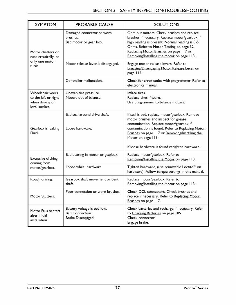
Motor chatters or runs erratically, or only one motor turns.
Damaged connector or worn brushes.Bad motor or gear box.
Ohm out motors. Check brushes and replace brushes if necessary. Replace motor/gearbox if high reading is present. Normal reading is 0-5 Ohms. Refer to Motor Testing on page 32, Replacing Motor Brushes on page 117 or Removing/Installing the Motor on page 113.
Motor release lever is disengaged. Engage motor release levers. Refer to Engaging/Disengaging Motor Release Lever on page 115.
Controller malfunction. Check for error codes with programmer. Refer to electronics manual.
Wheelchair veers to the left or right when driving on level surface.
Uneven tire pressure.Motors out of balance.
Inflate tires.Replace tires if worn.Use programmer to balance motors.
Gearbox is leaking Fluid.
Bad seal around drive shaft.
Loose hardware.
If seal is bad, replace motor/gearbox. Remove motor brushes and inspect for grease contamination. Replace motor/gearbox if contamination is found. Refer to Replacing Motor Brushes on page 117 or Removing/Installing the Motor on page 113.
If loose hardware is found retighten hardware.
Excessive clicking coming from motor/gearbox.
Bad bearing in motor or gearbox. Replace motor/gearbox. Refer to Removing/Installing the Motor on page 113.
Loose wheel hardware. Tighten hardware, (use removable Loctite™on hardware). Follow torque settings in this manual.
Rough driving. Gearbox shaft movement or bent shaft.
Replace motor/gearbox. Refer to Removing/Installing the Motor on page 113.
Motor Stutters.Poor connection or worn brushes. Check DCL connectors. Check brushes and
replace if necessary. Refer to Replacing Motor Brushes on page 117.
Motor Fails to start after initial installation.
Battery voltage is too low.Bad Connection.Brake Disengaged.
Check batteries and recharge if necessary. Refer to Charging Batteries on page 105.Check connector. Engage brake.
SYMPTOM PROBABLE CAUSE SOLUTIONS
Part No 1125075 27 Pronto® Series
SECTION 3—SAFETY INSPECTION/TROUBLESHOOTING
Battery
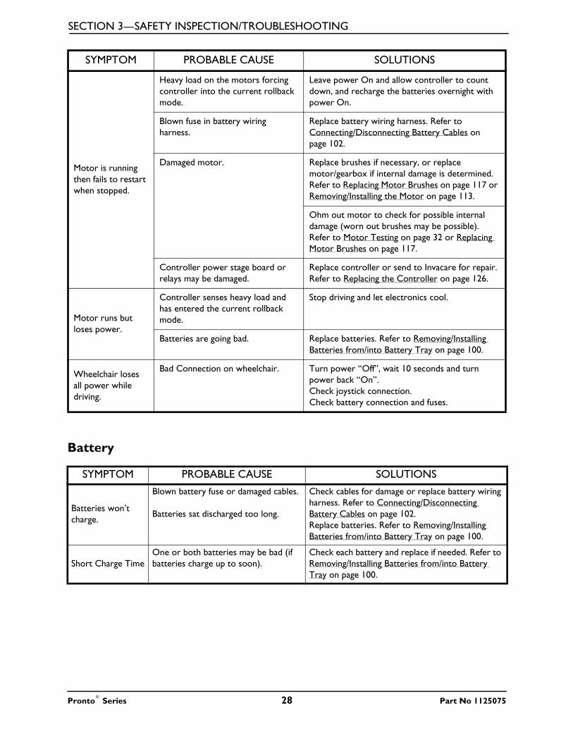
Motor is running then fails to restart when stopped.
Heavy load on the motors forcing controller into the current rollback mode.
Leave power On and allow controller to count down, and recharge the batteries overnight with power On.
Blown fuse in battery wiring harness.
Replace battery wiring harness. Refer to Connecting/Disconnecting Battery Cables on page 102.
Damaged motor. Replace brushes if necessary, or replace motor/gearbox if internal damage is determined. Refer to Replacing Motor Brushes on page 117 or Removing/Installing the Motor on page 113.
Ohm out motor to check for possible internal damage (worn out brushes may be possible). Refer to Motor Testing on page 32 or Replacing Motor Brushes on page 117.
Controller power stage board or relays may be damaged.
Replace controller or send to Invacare for repair. Refer to Replacing the Controller on page 126.
Motor runs but loses power.
Controller senses heavy load and has entered the current rollback mode.
Stop driving and let electronics cool.
Batteries are going bad. Replace batteries. Refer to Removing/Installing Batteries from/into Battery Tray on page 100.
Wheelchair loses all power while driving.
Bad Connection on wheelchair. Turn power “Off”, wait 10 seconds and turn power back “On”.Check joystick connection.Check battery connection and fuses.
SYMPTOM PROBABLE CAUSE SOLUTIONS
Batteries won’t charge.
Blown battery fuse or damaged cables.
Batteries sat discharged too long.
Check cables for damage or replace battery wiring harness. Refer to Connecting/Disconnecting Battery Cables on page 102.Replace batteries. Refer to Removing/Installing Batteries from/into Battery Tray on page 100.
Short Charge TimeOne or both batteries may be bad (if batteries charge up to soon).
Check each battery and replace if needed. Refer to Removing/Installing Batteries from/into Battery Tray on page 100.
SYMPTOM PROBABLE CAUSE SOLUTIONS
Pronto® Series 28 Part No 1125075

SECTION 3—SAFETY INSPECTION/TROUBLESHOOTING
Battery Charger
No power to wheelchair motors.
Bad connection or blown fuse. Check Joystick connection.
Batteries are dead.
Check all connections and housings for damage. If you have blown fuse a new battery wiring harness must be purchased. Refer to Connecting/Disconnecting Battery Cables on page 102.Check battery voltage and replace if necessary. Refer to Removing/Installing Batteries from/into Battery Tray on page 100.
Loose battery connections. Check battery cable connections, may have vibrated loose when driving on rough terrain.
Corroded battery wiring connections.
Possible water, salt, or urine damage.
Replace battery wiring harness. Refer to Connecting/Disconnecting Battery Cables on page 102.
SYMPTOM PROBABLE CAUSE SOLUTIONS
No LED’s on Charger
Charger not plugged into outlet, or disconnected from wiring harness on wheelchair.
Make sure the charger is plugged into the outlet and check the wiring on the wheelchair.
No AC power at outlet. Check for AC power with digital volt meter.
Damaged power cord. Check for damage on the power cord, replace if damaged or send to Invacare for repair.
Charger LED’s burnt out. Send charger to Invacare for repair.
Charger may have internal fuse that is blown.
Remove charger cover and check for fuses. iI fuses are present, Ohm out fuses and replace if necessary. Refer to Replacing the On-Board Battery Charger Fuse on page 109.
Batteries won’t charge.
Blown battery fuse in wiring harness, or charger.
Check battery wiring harness fuse on the wheelchair. Replace battery wiring harness if fuse is blown. Refer to Connecting/Disconnecting Battery Cables on page 102.Check fuse in the charger. Refer to Replacing the On-Board Battery Charger Fuse on page 109.
Charger not plugged into outlet. Make sure charger is plugged into the outlet.
No AC power at the outlet. Check for AC power with a digital volt meter.
Charger Power cord may bedamaged, or the connector may be damaged.
Check for damage and replace if necessary, or send in for repair.
Charger may have internal damage. Charge batteries with known good charger.
Battery voltage too low for charger to start charging cycle.
Replace batteries. Refer to Removing/Installing Batteries from/into Battery Tray on page 100.
SYMPTOM PROBABLE CAUSE SOLUTIONS
Part No 1125075 29 Pronto® Series

SECTION 3—SAFETY INSPECTION/TROUBLESHOOTING
M61 Only
Checking Battery Charge LevelThe following “Do’s” and “Don’ts” are provided for your convenience and safety.
Batteries have short driving range during a single charge. Battery Gauge falls off faster than normal.
Consumer not charging batteries long enough.
Instruct consumer to charge for 8-10 hours minimum.
Batteries may be weak. Perform load test or check “Battery Quality Menu” with the programmer. Refer to electronics manual. Refer to Field Load Test on page 31.
Check programming settings. Torque setting and power level setting may be too high. Refer to electronics manual.
Heavy load on motors. Chairs weight distribution may be offset (wheelchair may be front loaded).
SYMPTOM PROBABLE CAUSE SOLUTIONSWheelchair slows or stops while driving and the Seat Function I indicator is lit.
Elevating seat is elevated. Return seat to its lowest position. Refer to Elevating the Seat on page 38.
Elevating seat sensor is damaged. Examine elevating seat sensor. Replace if necessary. Refer to Removing/Installing the Actuator Switch Sensor on page 98.
DO DON’T
Read and understand this manual and any service information that accompanies a battery and charger before operating the wheelchair.
Don’t perform any installation or maintenance without first reading this manual.
Move the wheelchair to a work area before opening battery box or installing service batteries.
Don’t perform installation or maintenance of batteries in an area that could be damaged by battery spills.
Recharge as frequently as possible to maintain a high charge level and extend battery life.
Don’t make it a habit to discharge batteries to the lowest level.
Follow recommendations in this manual when selecting a battery or charger.
Don’t use randomly chosen batteries or chargers.
Fully charge new batteries before using. Don’t put new batteries into servcie before charging.
Use a carrying strap to remove, move or install a battery.
Don’t tip or tilt batteries.
Push battery clamps on the terminals. Spread clamps wider if necessary.
Don’t tap on clamps and terminals with tools.
Use ONLY a GEL charger for a GEL battery or “Sealed” battery.
Don’t mismatch your battery and chargers.
SYMPTOM PROBABLE CAUSE SOLUTIONS
Pronto® Series 30 Part No 1125075

SECTION 3—SAFETY INSPECTION/TROUBLESHOOTING
Field Load TestNOTE: For this procedure, refer to FIGURE 3.1 on page 32.
Old batteries lose their ability to store and release power, due to increased internal resistance. This means that as you try to take power from the battery, some of that power is used up in the process of passing through the battery, resulting in less voltage at the posts. The more power drawn, the lower the voltage available. When this lost voltage drops the output 1.0 volts under load (2.0 for a pair), replace the batteries.
To spot this problem, test batteries under load.
Use a digital voltmeter to check battery charge level at the charger connector. The charger connector is located on the joystick.NOTE: Read these instructions carefully and the manufacturer’s instructions on the digital voltmeter before using the digital voltmeter.
1. Ensure that power is Off.
2. Make sure battery is fully charged. An extremely discharged battery will exhibit the same symptoms as a bad one.
3. Remove the footrests from the wheelchair. Refer to Front Riggings/FootBoard on page 74.
4. Connect the voltmeter leads to the charger port on the wheelchair as shown in FIGURE 3.1. Most digital voltmeters are not affected by polarity, however, analog meters (meters with swinging needles) can be and should be used carefully. A good meter reading should be 25.5 to 26 VDC.
� WARNINGWhen performing STEPS 5 and 6, ensure feet are clear from casters and wall, otherwise injury may result.
5. Sit in wheelchair and place feet against a wall, workbench or other stationary object.
6. Turn the power On and carefully push the joystick forward, trying to drive the wheelchair through the stationary object.
NOTE: Performing STEP 6 puts a heavy load on the batteries as they try to push through the stationary object. If the wheels spin, have two individuals (one on each arm) apply as much downward pressure as possible on the arms of the wheelchair.
7. Read the meter while the motors are straining, no longer than 3-4 seconds, to determine the voltage under load.
NOTE: If the voltage drops more than 2 volts from a pair of fully charged batteries while under load, they should be replaced regardless of the unloaded voltages.
Part No 1125075 31 Pronto® Series

SECTION 3—SAFETY INSPECTION/TROUBLESHOOTING
FIGURE 3.1 Field Load Test
Motor TestingNOTE: For this procedure, refer to FIGURE 3.2.
1. On the 4-pin motor connector, locate the two contacts in the RED and BLACK housings.
2. Set the digital multimeter to measure resistance (ohms).
3. Measure the resistance between the two motor contacts.
NOTE: A normal reading is between .5 and 5 ohms. A reading of 0 ohms or in excess of 15 ohms indicates a problem. High readings are generally caused by bad connections and/or damaged brushes. Contact Invacare. FIGURE 3.2 Motor Testing
Charger Port
Digital Voltmeter
BATTERYQUALITY
0 to 2 volts Good
2 to 2.5 volts Poor
2.5 or more Bad
4 Pin Motor Connector
MotorCap
Pronto® Series 32 Part No 1125075

SECTION 4—WHEELCHAIR OPERATION
SECTION 4—WHEELCHAIR OPERATION
� DANGERRisk of Death, Serious Injury, or DamageMalfunctioning joystick could cause unintended/erratic movement resulting in death, serious injury, or damage.If unintended/erratic movement occurs, stop using the wheelchair immediately and contact a qualified technician.
� WARNINGAfter any adjustments, repair or service and before use, make sure that all attaching hardware is tightened securely - otherwise injury or damage may result.Set-up of the Electronic Control Unit is to be performed only by a qualified technician. The final adjustments of the controller may affect other activities of the wheelchair. Damage to the equipment could occur if improperly set-up or adjusted.
Turning the Power On/Off
M50 and M51 Wheelchairs Manufactured Before 8/15/05NOTE: For this procedure, refer to FIGURE 4.1.
1. Turn the power On by moving the On/Off switch up or down. The switch automatically retracts back to center position.
NOTE: After turning power On, all indicators will light briefly and the display gauge will indicate one of the following:
• The Current Battery Charge - Information gauge shows all LEDs lit or partial LEDs lit. Refer to table in Information Gauge Display on page 40.
• Out Of Neutral At Power Up - Information Gauge shows all LEDs flashing slowly. This occurs when the power is turned On when the joystick is out of neutral. This feature prevents sudden and unexpected movements of the power chair.
2. Turning the power Off can be achieved by moving the On/Off switch up or down. The switch automatically retracts back to center position.
Part No 1125075 33 Pronto® Series

SECTION 4—WHEELCHAIR OPERATION
FIGURE 4.1 Turning the Power On/Off - M50 and M51 Wheelchairs Manufactured Before 8/15/05
M50/M51 Wheelchairs Manufactured After 8/14/05 and all M61 WheelchairsNOTE: For this procedure, refer to FIGURE 4.2.
1. Turn the power On by pressing the On/Off button.
NOTE: After turning power On, the battery gauge indicators will light briefly. One of the following will occur after that:
• The current battery charge will be indicated on the information gauge display.
• Lock Mode will be indicated by all LEDs flashing briefly and the information gauge LEDs chasing slowly from right to left. If this occurs, press the horn button two times within ten seconds to unlock the joystick.
2. Turning the power Off by pressing the On/Off button.
FIGURE 4.2 Turning the Power On/Off - M50/M51 Wheelchairs Manufactured After
8/14/05 and all M61 WheelchairsNOTE: If the joystick has been programmed for lock mode, holding the On/Off button down for four seconds will lock the joystick. The LEDs will flash briefly and the horn will sound a short beep.
Using the Joystick to Drive the Wheelchair
� WARNINGDO NOT operate wheelchair on an incline while in an elevated position. Otherwise, the wheelchair may tip over and injury or damage may occur.
NOTE: For this procedure, refer to FIGURE 4.3 on page 35.
INVACARE
Information Gauge
ON/OFF Toggle Switch
On/Off Button
Information Gauge Display
NOTE: SPJ™+ w/ACC joystick shown. SPJ™+ joystick works the same way.
Pronto® Series 34 Part No 1125075

SECTION 4—WHEELCHAIR OPERATION
The joystick provides smooth control of speed and direction. It is equipped with 360 degrees of mobility for ease of operation. The joystick is spring-loaded, and automatically returns to the upright (neutral) position when released. Pushing the joystick in a given direction causes the chair to move in that direction.
The joystick has proportional control, meaning that the further it is pushed from the upright (neutral) position, the faster the wheelchair moves or the seat elevates/lowers. The maximum speed, however, is limited by the speed setting.
To slow the wheelchair to a stop, simply release the joystick. The wheelchair has automatic speed and direction compensation to minimize corrections.
When first learning to drive, select a slow speed and try to drive the wheelchair as slowly as possible by pushing the joystick slightly forward. This exercise will help you learn to utilize the full potential of the proportional control and allow you to start and stop smoothly.
To drive the wheelchair, perform the following:
1. Turn the power On. Refer to Turning the Power On/Off on page 33.
2. Adjust speed. Refer to Adjusting the Speed on page 36.
3. Maneuver the joystick in the following manner:
FIGURE 4.3 Using the Joystick to Drive the Wheelchair
MOVEMENT ACTIONFORWARD Push forward on the joystick.
REVERSE Pull back on the joystick.
Turn RIGHT Move the joystick RIGHT.
Turn LEFT Move the joystick LEFT.
STOP Release the joystick and the wheelchair will quickly slow down.
To Move Forward
To Move Right
To Move Left
To Move Backward
Joystick
M50 and M51 Wheelchairs Manufactured Before 8/15/05
M50/M51 Wheelchairs Manufactured After 8/14/05 and All M61 Wheelchairs
Joystick
To Move Left
To Move Forward
To Move Right
To Move Backward
NOTE: SPJ™+ w/ACC joystick shown. SPJ™+ joystick works the same way.
Part No 1125075 35 Pronto® Series
SECTION 4—WHEELCHAIR OPERATION
Adjusting the Speed
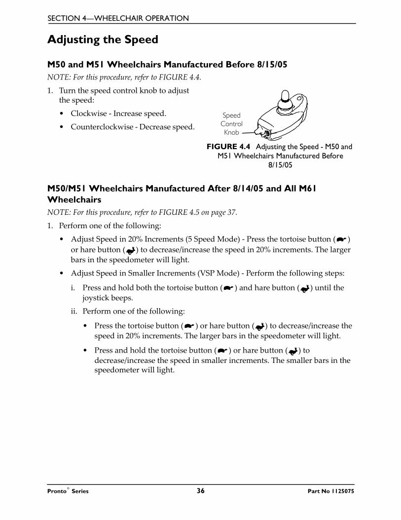
M50 and M51 Wheelchairs Manufactured Before 8/15/05NOTE: For this procedure, refer to FIGURE 4.4.
1. Turn the speed control knob to adjust the speed:
• Clockwise - Increase speed.
• Counterclockwise - Decrease speed.
FIGURE 4.4 Adjusting the Speed - M50 and M51 Wheelchairs Manufactured Before
8/15/05
M50/M51 Wheelchairs Manufactured After 8/14/05 and All M61 WheelchairsNOTE: For this procedure, refer to FIGURE 4.5 on page 37.
1. Perform one of the following:
• Adjust Speed in 20% Increments (5 Speed Mode) - Press the tortoise button ( ) or hare button ( ) to decrease/increase the speed in 20% increments. The larger bars in the speedometer will light.
• Adjust Speed in Smaller Increments (VSP Mode) - Perform the following steps:
i. Press and hold both the tortoise button ( ) and hare button ( ) until the joystick beeps.
ii. Perform one of the following:
• Press the tortoise button ( ) or hare button ( ) to decrease/increase the speed in 20% increments. The larger bars in the speedometer will light.
• Press and hold the tortoise button ( ) or hare button ( ) to decrease/increase the speed in smaller increments. The smaller bars in the speedometer will light.
Speed Control Knob
Pronto® Series 36 Part No 1125075

SECTION 4—WHEELCHAIR OPERATION
FIGURE 4.5 Adjusting the Speed - M50/M51 Wheelchairs Manufactured After 8/14/05 and All M61 Wheelchairs
Using the Horn
M50 and M51 Wheelchairs Manufactured Before 8/15/05NOTE: For this procedure, refer to FIGURE 4.6.
1. Press the horn button located above the information gauge on the joystick housing.
FIGURE 4.6 Using the Horn - M50 and M51 Wheelchairs Manufactured Before
8/15/05
M50/M51 Wheelchairs Manufactured After 8/14/05 and All M61 WheelchairsNOTE: For this procedure, refer to FIGURE 4.7.
1. Press the horn button located in the center of the speed indicator. The horn will sound for as long as the button is pressed.
FIGURE 4.7 Using the Horn - M50/M51 Wheelchairs Manufactured After 8/14/05 and
All M61 Wheelchairs
Tortoise Button Hare Button
Larger Bar in Speedometer
Smaller Bar in Speedometer
NOTE: SPJ+ w/ACC joystick shown. SPJ+ joystick works the same way.
Horn Button
Horn Button
NOTE: SPJ+ w/ACC joystick shown. SPJ+ joystick works the same way.
Part No 1125075 37 Pronto® Series

SECTION 4—WHEELCHAIR OPERATION
Elevating the Seat
� WARNINGDO NOT operate wheelchair on an incline while in an elevated position. Otherwise, the wheelchair may tip over and injury or damage may occur.DO NOT operate the elevate function near or under a fixed object such as a table or desk.Use only the MK5™NX w/ACC or MK660 w/ACC controller to activate the elevate function. DO NOT use any other actuator controls. Such devices may result in excess heating and cause damage to the actuator and associated wiring and could cause a fire, death, physical injury or property damage. If such devices are used, Invacare shall not be liable and the limited warranty is void.The elevated seat option is equipped with a speed reduction safety mechanism. While the seat is in an elevated position, the safety feature slows the speed of the wheelchair by 80%. If the wheelchair operates at maximum speed while in an elevated position, DO NOT operate the wheelchair. Have the wheelchair serviced IMMEDIATELY by a qualified technician.
NOTE: For this procedure, refer to FIGURE 4.8.
NOTE: This procedure applies to M61 wheelchairs only.
1. Make sure the wheelchair is on a level surface.
2. Press the mode button to switch from driving mode to elevate mode.
NOTE: The LED will light up with a circle around it.
3. Move the joystick:
• Forward - Elevates the seat.
• Backward - Lowers the seat.
Pronto® Series 38 Part No 1125075

SECTION 4—WHEELCHAIR OPERATION
FIGURE 4.8 Elevating the Seat
SPJ™Joystick Switches and IndicatorsNOTE: For the following information, refer to FIGURE 4.9.
NOTE: The SPJ joystick is used on M50 and M51 wheelchairs manufactured before 8/15/05 only.
FIGURE 4.9 SPJ™Joystick Switches and Indicators
On/Off Toggle Switch
This toggle switch is located at the back of the joystick housing.
Mode Button
Elevate the Seat
Lower the Seat
Joystick
Elevated Seat
Selected Drive Mode
Joystick
Speed Control Knob
On/Off Toggle Switch
Charger/Programming Input
To Controller
Part No 1125075 39 Pronto® Series

SECTION 4—WHEELCHAIR OPERATION
Speed Control Knob
The speed control knob is located on the back of the joystick housing. This rotary switch is used for controlling the speed and acceleration of the wheelchair.
1. Turn the switch clockwise to increase the speed of the wheelchair.
2. Turn the switch counterclockwise to decrease the speed of the wheelchair.
Joystick
The joystick has proportional drive control, meaning that further the wheelchair is pushed from the upright (neutral) position, the faster it moves. Your top speed, however, is limited by the setting of the speed-control knob and programmed settings.
To slow the wheelchair to a stop, simply release the joystick. The wheelchair has automatic speed and direction compensation to minimize corrections.
Charger/Programming Input
Located at the front of the joystick housing. This provides easy access for charging the wheelchair batteries. This port also serves as the Remote Programmer Communication connection.
Information Gauge Display
Located on the front of the joystick housing, it provides the following information to the user on the status of the wheelchair -
1. Power is On.
2. True state-of-battery-charge, including notification of when the battery requires charging:
A. GREEN LED is lit, indicating well charged batteries.
B. Only AMBER LEDs are lit, indicating batteries are moderately charged. Recharge batteries before taking a long trip.
C. Only RED LED is lit, indicating batteries are running out of charge. Recharge batteries as soon as possible.
The Information Gauge display also serves as a system diagnostic device when a fault is detected by the control module. A specific number of flashes of the LEDs indicate the type of fault detected. Refer to SPJ Information Gauge Display Diagnostics on page 23.
Pronto® Series 40 Part No 1125075

SECTION 4—WHEELCHAIR OPERATION
SPJ+ and SPJ+ w/ACC Joystick Switches and IndicatorsNOTE: For the following information, refer to FIGURE 4.10.
NOTE: SPJ+ joysticks are used on M50/M51 wheelchairs manufactured after 8/14/05.
NOTE: SPJ+ w/ACC joysticks are used on M61 wheelchairs.
FIGURE 4.10 SPJ+ and SPJ+ w/ACC Joystick Switches and Indicators
On/Off Button
DETAIL “A” - FRONT VIEW
Charger/Programming Input
Speedometer
Joystick
GREEN LED
Information Gauge Display
Service Indicator
Decrease Speed Button
(Tortoise) Increase Speed Button
(Hare)
Mode Button
SPJ+ w/ACC Joystick
On/Off Button
DETAIL “A” - FRONT VIEW
Charger/Programming Input
Speedometer
Joystick
GREEN LED
Information Gauge Display
Service Indicator
Decrease Speed Button
(Tortoise) Increase Speed Button
(Hare)
SPJ+ Joystick
Part No 1125075 41 Pronto® Series
SECTION 4—WHEELCHAIR OPERATION
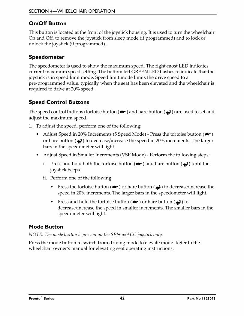
On/Off Button
This button is located at the front of the joystick housing. It is used to turn the wheelchair On and Off, to remove the joystick from sleep mode (if programmed) and to lock or unlock the joystick (if programmed).
Speedometer
The speedometer is used to show the maximum speed. The right-most LED indicates current maximum speed setting. The bottom left GREEN LED flashes to indicate that the joystick is in speed limit mode. Speed limit mode limits the drive speed to a pre-programmed value, typically when the seat has been elevated and the wheelchair is required to drive at 20% speed.
Speed Control Buttons
The speed control buttons (tortoise button ( ) and hare button ( )) are used to set and adjust the maximum speed.
1. To adjust the speed, perform one of the following:
• Adjust Speed in 20% Increments (5 Speed Mode) - Press the tortoise button ( ) or hare button ( ) to decrease/increase the speed in 20% increments. The larger bars in the speedometer will light.
• Adjust Speed in Smaller Increments (VSP Mode) - Perform the following steps:
i. Press and hold both the tortoise button ( ) and hare button ( ) until the joystick beeps.
ii. Perform one of the following:
• Press the tortoise button ( ) or hare button ( ) to decrease/increase the speed in 20% increments. The larger bars in the speedometer will light.
• Press and hold the tortoise button ( ) or hare button ( ) to decrease/increase the speed in smaller increments. The smaller bars in the speedometer will light.
Mode ButtonNOTE: The mode button is present on the SPJ+ w/ACC joystick only.
Press the mode button to switch from driving mode to elevate mode. Refer to the wheelchair owner’s manual for elevating seat operating instructions.
Pronto® Series 42 Part No 1125075

SECTION 4—WHEELCHAIR OPERATION
Joystick
The joystick has proportional drive control, meaning that further the joystick is pushed from the upright (neutral) position, the faster the wheelchair or seat moves. Your top speed, however, is limited by the programmed settings.
To slow the wheelchair to a stop, simply release the joystick. The wheelchair has automatic speed and direction compensation to minimize corrections.
Charger/Programming Input
The charger/programming input is located at the front of the joystick housing. This provides easy access for charging the wheelchair batteries. This port also serves as the Remote Programmer Communication connection. Driving is prevented while the system is charging.
Service Indicator
The AMBER service indicator will light when an error or fault occurs. Refer to electronics manual supplied with wheelchair.
Information Gauge Display
Located on the front of the joystick housing, it provides the following information to the user on the status of the wheelchair -
1. Power is On.
2. True state-of-battery-charge, including notification of when the battery requires charging:
A. GREEN LEDs are lit, indicating well charged batteries.
B. AMBER LEDs are lit, indicating batteries are moderately charged. Recharge batteries before taking a long trip.
C. RED LEDs are lit, indicating batteries are running out of charge. Recharge batteries as soon as possible.
The Information Gauge display also serves as a system diagnostic device when a fault is detected by the control module. A specific number of flashes of the LEDs indicate the type of fault detected. Refer to the table for the diagnostic indications of the wheelchair status.
Part No 1125075 43 Pronto® Series

SECTION 5—ARMS
SECTION 5—ARMS
� WARNINGAfter any adjustments, repair or service and before use, make sure that all attaching hardware is tightened securely - otherwise injury or damage may result.
Before performing any maintenance, adjustment or service verify that On/Off switch on the joystick is in the Off position.
Removing/Installing Van Seat ArmNOTE: For this procedure, refer to FIGURE 5.1 on page 45.
NOTE: Reverse this procedure to install the adjustable width arms.
1. If necessary, disconnect the joystick. Disconnecting/Connecting the Joystick on page 124.
2. Loosen lock knob that secures the adjustable width arm to the arm support tube.
3. Remove the adjustable width arm from the arm support tube.
4. If necessary, repeat STEPS 1-3 to remove the remaining adjustable width arm.
Adjusting Van Seat Arm Width
� WARNINGIncreasing the width of the arms may affect the overall width of the wheelchair. Ensure that there is enough clearance when attempting to pass through doorways or other tight spaces, otherwise serious injury or damage may result.
NOTE: For this procedure, refer to FIGURE 5.1 on page 45.
1. Loosen the two lock knobs that secure the adjustable width arms to the arm support tube.
NOTE: Both adjustable width arms should be adjusted to the same distance away from the arm support tube.
NOTE: Changing the width of the adjustable width arms may also effect the overall width of the wheelchair.
2. Reposition adjustable width arms until desired width is achieved.
3. Securely tighten the two lock knobs that secure the adjustable width arms to the arm support tube.
Pronto® Series 44 Part No 1125075

SECTION 5—ARMS
FIGURE 5.1 Removing/Installing Van Seat Arm and Adjusting Van Seat Arm Width
Adjusting Van Seat Arm Angle
� WARNINGPinch point may occur when adjusting the arm angle position.
NOTE: For this procedure, refer to FIGURE 5.2 on page 46.
1. Lift-up the armrest.
2. Loosen the jam nut.
3. Adjust the socket screw up or down to the desired arm angle position.
4. Tighten the jam nut.
5. To determine the same angle for the opposite armrest, count the exposed threads after the jam nut has been tightened.
6. Repeat STEPS 1-5 for opposite armrest, if necessary.
Adjusting Van Seat Arm Height (Adjustable Height Arms Only) NOTE: For this procedure, refer to FIGURE 5.2 on page 46.
1. Remove the lock knob that secures the armrest to the arm frame assembly.
2. Adjust the armrest to one of five positions in 1-inch increments.
3. Reinstall the lock knob that secures the armrest to the arm frame assembly and tighten securely.
Lock Knob(s)
Arm Support Tube
Adjustable Width Arm
Part No 1125075 45 Pronto® Series

SECTION 5—ARMS
FIGURE 5.2 Adjusting Van Seat Arm Height (Adjustable Height Arms Only)
Replacing Van Seat Armrest AssemblyNOTE: For this procedure, refer to FIGURE 5.3.
1. If necessary, remove the joystick. Removing/Installing the Joystick on page 121.
2. Remove the mounting screw, washers and locknut that secure the existing armrest assembly to the arm post.
3. Position the new armrest assembly on the armrest post and secure with the mounting screw, washers, and locknut. Refer to FIGURE 5.3 for correct hardware orientation.
4. If necessary, install the joystick. Removing/Installing the Joystick on page 121.
5. Repeat STEPS 1-4 for the opposite armrest assembly, if necessary.
FIGURE 5.3 Replacing Van Seat Armrest Assembly
Angle Height
Height Adjustment
HolesLock Knob
Arm Frame Assembly
Armrest
Pinch Point
Jam NutCount Exposed Threads
ArmrestSocket Screw
Mounting ScrewArm Post
Locknut
Armrest Assembly
Washers
Washer
Pronto® Series 46 Part No 1125075

SECTION 5—ARMS
Removing/Installing Flip Back Armrest
� WARNINGMake sure the flip back armrest release levers and height adjustment levers are in the locked position before using the wheelchair.
NOTE: For this procedure, refer to FIGURE 5.4.
NOTE: Flip back armrest release lever MUST be in unlocked position when placing armrest into the arm sockets.
NOTE: Reverse this procedure to install the flip back armrest.
1. If necessary, disconnect the joystick. Disconnecting/Connecting the Joystick on page 124.
2. Unlock flip back armrest by pulling flip back armrest release lever into the unlocked (horizontal) position.
3. Remove quick release pin securing the flip back armrest to the wheelchair frame.
4. Pull up on the flip back armrest and remove the armrest from the arm sockets.
5. Repeat STEPS 1-4 for the opposite flip back armrest, if necessary.
FIGURE 5.4 Removing/Installing Flip Back Armrest
Flip Back Armrest
Rear Arm Socket
Quick Release PinFront Arm Socket
Seat Frame
Flip Back Armrest Release Lever
Locked (Vertical)
Unlocked (Horizontal)
Part No 1125075 47 Pronto® Series
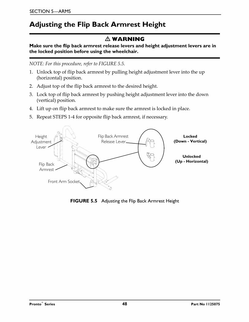
SECTION 5—ARMS
Adjusting the Flip Back Armrest Height
� WARNINGMake sure the flip back armrest release levers and height adjustment levers are in the locked position before using the wheelchair.
NOTE: For this procedure, refer to FIGURE 5.5.
1. Unlock top of flip back armrest by pulling height adjustment lever into the up (horizontal) position.
2. Adjust top of the flip back armrest to the desired height.
3. Lock top of flip back armrest by pushing height adjustment lever into the down (vertical) position.
4. Lift up on flip back armrest to make sure the armrest is locked in place.
5. Repeat STEPS 1-4 for opposite flip back armrest, if necessary.
FIGURE 5.5 Adjusting the Flip Back Armrest Height
Locked (Down - Vertical)
Unlocked (Up - Horizontal)
Height Adjustment
Lever
Flip Back Armrest
Front Arm Socket
Flip Back Armrest Release Lever
Pronto® Series 48 Part No 1125075

SECTION 6—VAN SEAT
SECTION 6—VAN SEAT
� WARNINGAfter any adjustments, repair or service and before use, make sure that all attaching hardware is tightened securely - otherwise injury or damage may result.
Before performing any maintenance, adjustment or service verify that On/Off switch on the joystick is in the Off position.
Adjusting the Back Angle
Semi-Recline Back AngleNOTE: For this procedure, refer to FIGURE 6.1.
1. Lift up on the release handle and adjust seat to desired angle.
2. Let go of the release handle to lock the back in position.
FIGURE 6.1 Adjusting the Back Angle - Semi-Recline Back Angle
Fold Down Back AngleNOTE: For this procedure, refer to FIGURE 6.2 on page 50.
1. Remove the two shoulder bolts and locknuts from the seat hinges on either side of the seat.
2. Select one of the four back angle positions as shown in Detail “A” of FIGURE 6.2.
3. Reinstall and tighten the two shoulder bolts and locknuts through the desired back angle setting on each seat hinge.
NOTE: Both seat hinges should be set to the same back angle setting.
Release Handle
NOTE: Office style van seat is shown. Standard van seat operates the same way.
Office Style Van Seat
Part No 1125075 49 Pronto® Series
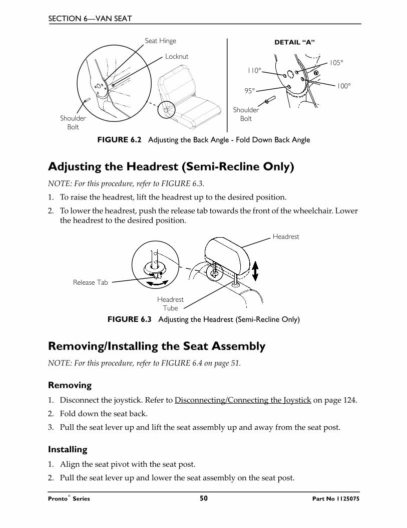
SECTION 6—VAN SEAT
FIGURE 6.2 Adjusting the Back Angle - Fold Down Back Angle
Adjusting the Headrest (Semi-Recline Only)NOTE: For this procedure, refer to FIGURE 6.3.
1. To raise the headrest, lift the headrest up to the desired position.
2. To lower the headrest, push the release tab towards the front of the wheelchair. Lower the headrest to the desired position.
FIGURE 6.3 Adjusting the Headrest (Semi-Recline Only)
Removing/Installing the Seat AssemblyNOTE: For this procedure, refer to FIGURE 6.4 on page 51.
Removing
1. Disconnect the joystick. Refer to Disconnecting/Connecting the Joystick on page 124.
2. Fold down the seat back.
3. Pull the seat lever up and lift the seat assembly up and away from the seat post.
Installing
1. Align the seat pivot with the seat post.
2. Pull the seat lever up and lower the seat assembly on the seat post.
Seat Hinge
Locknut
Shoulder Bolt
DETAIL “A”
100°95°
110°105°
Shoulder Bolt
Headrest
Release Tab
Headrest Tube
Pronto® Series 50 Part No 1125075

SECTION 6—VAN SEAT
NOTE: If necessary, slightly twist seat assembly back and forth to lock it in place.
3. Release the seat lever.
4. Pull the seat assembly up to ensure that it is locked in place.
5. Connect the joystick. Refer to Disconnecting/Connecting the Joystick on page 124.
FIGURE 6.4 Removing/Installing the Seat Assembly
Adjusting Seat DepthNOTE: For this procedure, refer to FIGURE 6.5 on page 52.
1. Remove the seat. Refer to Removing/Installing the Seat Assembly on page 50.
2. Perform one of the following:
• For Standard Van Seat -
i. Remove the seat base from the seat assembly. Refer to Adjusting Seat Position on Seat Base on page 56.
ii. Go to STEP 3.
• For Office Style Seat - Go to STEP 3.
3. Remove the six mounting screws located under the seat that secure the seat back assembly in place.
4. Adjust seat back assembly to desired position and reinstall the six mounting screws. Securely tighten.
Seat Assembly
Seat Lever
Seat Post
NOTE: Office style van seat is shown. Standard van seat installs the same way.
Part No 1125075 51 Pronto® Series

SECTION 6—VAN SEAT
NOTE: Refer to Detail “A” of FIGURE 6.5 for proper seat depth positions. For example, to achieve maximum seat depth, the front mounting hole on the seat back bracket aligns with the third hole on the seat base.
5. Perform one of the following:
• For Standard Van Seat -
i. Install the seat base onto the seat assembly. Refer to Adjusting Seat Position on Seat Base on page 56.
ii. Go to STEP 6.
• For Office Style Seat - Go to STEP 6.
6. Reinstall the seat base onto the seat assembly. Refer to Adjusting Seat Position on Seat Base on page 56.
7. Reinstall the seat. Refer to Removing/Installing the Seat Assembly on page 50.
FIGURE 6.5 Adjusting Seat Depth
Mounting Holes
Mounting Screws
Seat Back
NOTE: Office style van seat is shown. Standard van seat adjusts the same way.
Seat Back Bracket
Seat Base Seat Depth Seat Size
16 inch 16 X 18 inch
16 inch 18 X 18 inch
18 inch 20 X 20 inch
18 inch 22 X 20 inch
Minimum Seat Depth
Seat Depth Seat Size17 inch 16 X 18 inch
17 inch 18 X 18 inch
19 inch 20 X 20 inch
19 inch 22 X 20 inch
Middle Seat Depth
Seat Depth Seat Size18 inch 16 X 18 inch
18 inch 18 X 18 inch
20 inch 20 X 20 inch
20 inch 22 X 20 inch
Maximum Seat Depth
DETAIL “A” - SEAT DEPTH POSITIONS
Pronto® Series 52 Part No 1125075

SECTION 6—VAN SEAT
Adjusting the Seat Height
M50/M51 WheelchairsNOTE: For this procedure, refer to FIGURE 6.6.
NOTE: The seat can be adjusted to five height positions in 1-inch increments.
1. Remove the seat. Refer to Removing/Installing the Seat Assembly on page 50.
2. Remove the mounting screw that secures the seat post to the support tube.
� WARNINGRefer to the table in FIGURE 6.8 on page 57 for proper seat post mounting positions. For users over 220 lbs - Mounting holes 3, 4 and 5 (in FIGURE 6.6) MUST be used with the seat in the 1-inch back position (FIGURE 6.8). Refer to Adjusting Seat Position on Seat Base on page 56.
3. Adjust the seat post to desired mounting position.
4. Reinstall mounting screw. Securely tighten.
5. Reinstall the seat. Refer to Removing/Installing the Seat Assembly on page 50.
FIGURE 6.6 Adjusting the Seat Height - M50/M51 Wheelchairs
Mounting Screw
Seat Post
Support Tube
Mounting Positions
NOTE: Batteries and shrouds not shown for clarity.
12345
Part No 1125075 53 Pronto® Series

SECTION 6—VAN SEAT
M61 WheelchairsNOTE: For this procedure, refer to FIGURE 6.7 on page 55.NOTE: Seat height can be increased by one or two inches. Use the chart to determine the desired height of the seat.
NOTE: A maximum of two sets of spacers can be installed.
1. Remove the seat. Refer to Removing/Installing the Seat Assembly on page 50.
2. Perform one of the following:
• For Standard Van Seats - Remove the four mounting screws, washers, and locknuts securing the seat pivot and four 1-inch adjustment spacers to the seat mounting bracket.
• For Office Style Van Seats - Remove the four mounting screws and washers securing the seat pivot and four 1-inch adjustment spacers to the seat base.
3. Perform one of the following:
• To Reduce Seat Height by One Inch - Remove one set of 1-inch adjustment spacers to achieve desired height.
• To Reduce Seat Height by Two Inches - Remove both sets of 1-inch adjustment spacers to achieve desired height.
4. Perform one of the following:
NOTE: The seat comes installed with four 1-inch spacers secured by either 3-inch or 3½-inch mounting screws. 1-inch, 2-inch, and 2½-inch mounting screws are supplied with the seat.
• For Seat Height Reduced by One Inch -
i. Align the mounting holes on the seat pivot with the mounting holes on the adjustment spacers and either the seat mounting bracket on standard van seats or the seat base on office style van seats.
ii. Install the seat adapter to seat base using the 2-inch mounting screws and existing washers and locknuts (if required). Securely tighten.
• For Seat Height Reduced by Two Inches -
i. Align the mounting holes on the seat pivot with the mounting holes on the adjustment spacers and either the seat mounting bracket on standard van seats or the seat base on office style van seats.
ii. Install the seat adapter to seat base using the 1-inch mounting screws and existing washers and locknuts (if required). Securely tighten.
5. Reinstall the seat. Refer to Removing/Installing the Seat Assembly on page 50.
INCREASE IN SEAT HEIGHT
SETS OF SEAT SPACERS
TOTAL NUMBER OF SPACERS
LENGTH OF MOUNTING SCREWS
1 inch 1 22½-inches (Office Style Van Seat)
2-inches (Standard Van and ASBA Seat)
2 inch 2 43½-inches (Office Style Van Seat)
3-inches (Standard Van and ASBA Seat)
Pronto® Series 54 Part No 1125075

SECTION 6—VAN SEAT
CAUTIONSpacers should be placed in orientation shown, otherwise they will interfere with the seat lever.
FIGURE 6.7 Adjusting the Seat Height - M61 Wheelchairs
WashersMounting Screws
NOTE: Three-inch and three-and-a-half mounting screws shown. One-inch and two-inch mounting screws are supplied with the seat.
Seat Pivot
1-inch Adjustment
Spacers
Seat Base
1-inch Adjustment
Spacers
1-inch Adjustment
Spacers
1-inch Adjustment
Spacers
Washers
Mounting Screws
Seat Pivot
Seat Mounting Bracket
Standard Van SeatOffice Style Van Seat
Locknuts
Part No 1125075 55 Pronto® Series
SECTION 6—VAN SEAT
Adjusting Seat Position on Seat Base
� WARNINGRefer to the table in FIGURE 6.8 for proper seat post mounting positions. For users over 220 lbs - seat MUST be in the 1-inch back position (FIGURE 6.8) when using seat post mounting holes 3, 4 and 5 (FIGURE 6.6). Refer to Adjusting the Seat Height on page 53.
NOTE: For this procedure, refer to FIGURE 6.8 on page 57.
1. Remove the seat. Refer to Removing/Installing the Seat Assembly on page 50.
2. Remove the four mounting screws and washers securing the seat pivot to the seat base (FIGURE 6.8).
3. Separate the seat pivot from the seat base.
4. Refer to FIGURE 6.8 to determine the correct mounting holes to achieve the desired seat position.
5. Align the mounting holes on the seat pivot (determined in STEP 4) with the mounting holes on the seat base.
6. Using the four mounting screws and washers, secure the seat base to the seat assembly. Securely tighten.
7. Reinstall the seat. Refer to Removing/Installing the Seat Assembly on page 50.
Pronto® Series 56 Part No 1125075

SECTION 6—VAN SEAT
FIGURE 6.8 Adjusting Seat Position on Seat Base
WEIGHT LIMITATION
SEAT POST MOUNTING HOLE
1-INCH BACK
STANDARD 1-INCH FORWARD
300 LBS
1 Y Y N/A
2 Y Y N/A
3 Y N/A N/A
4 Y N/A N/A
5 Y N/A N/A
220 LBS
1 Y Y Y
2 Y Y N/A
3 Y N/A N/A
4 Y N/A N/A
5 Y N/A N/A
150 LBS
1 Y Y Y
2 Y Y Y
3 Y Y Y
4 Y Y Y
5 Y Y Y
Bolts
Washers
Seat Base
DETAIL “A” - SEAT POSITION
I-inch Back Seat Position
I-inch Back Seat Position
I-inch Back Seat Position
Standard Seat
Position
Standard Seat
Position
Standard Seat
PositionStandard
Seat Position
Front of Seat
Rear of Seat
Seat Assembly
I-inch Forward Position*
I-inch Forward Seat Position*
I-inch Back Seat Position
DETAIL “B” - PROPER SEAT POSITIONS FOR 18-INCH DEEP BACK SETTING
Legend: Y - Use N/A - DO NOT Use
*NOTE: For users over 220 lbs - DO NOT use 1-inch forward position.
I-inch Forward Position*
I-inch Forward Position*
NOTE: Office style van seat is shown. Standard van seat adjusts the same way.
Part No 1125075 57 Pronto® Series

SECTION 6—VAN SEAT
Replacing the Seat Positioning Strap
� WARNINGALWAYS wear your seat positioning strap. The seat positioning strap is a positioning belt only. It is not designed for use as a safety device withstanding high stress loads such as auto or aircraft safety belts. If signs of wear appear, belt MUST be replaced IMMEDIATELY.
NOTE: For this procedure, refer to FIGURE 6.9.
1. Remove the two mounting screws that secure the seat positioning straps to the seat frame.
2. Remove the two halves of the seat positioning strap from the rear seat frame.
3. Reposition the two new seat positioning strap halves underneath seat rails.
4. Reinstall the two mounting screws that secure the seat positioning straps to the seat frame. Securely tighten.
FIGURE 6.9 Replacing the Seat Positioning Strap
Seat Positioning Strap
Seat Positioning Strap Mounting Screws
Seat
Seat Lever
NOTE: Office style van seat is shown. Standard van seat adjusts the same way.
Pronto® Series 58 Part No 1125075

SECTION 7—ASBA SEAT
SECTION 7—ASBA SEAT
� WARNINGAfter any adjustments, repair or service and before use, make sure that all attaching hardware is tightened securely - otherwise injury or damage may result.
Before performing any maintenance, adjustment or service verify that On/Off switch on the joystick is in the Off position.
Removing/Installing the Seat AssemblyNOTE: For this procedure, refer to FIGURE 7.1 on page 59.
Removing
1. Disconnect the joystick. Refer to Disconnecting/Connecting the Joystick on page 124.
2. Fold down the seat back.
3. Pull the seat lever up and lift the seat assembly up and away from the seat post.
Installing
1. Align the seat pivot with the seat post
2. Pull the seat lever up and lower the seat assembly on the seat post.
NOTE: If necessary, slightly twist seat assembly back and forth to lock it in place.
3. Release the seat lever.
4. Pull the seat assembly up to ensure that it is locked in place.
5. Connect the joystick. Refer to Disconnecting/Connecting the Joystick on page 124.
FIGURE 7.1 Removing/Installing the Seat Assembly
Seat Assembly
Seat LeverSeat Post
Part No 1125075 59 Pronto® Series
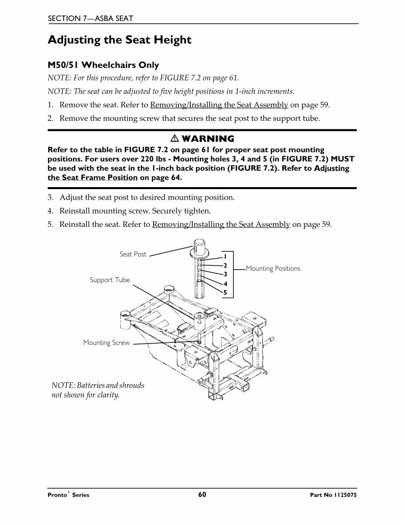
SECTION 7—ASBA SEAT
Adjusting the Seat Height
M50/51 Wheelchairs OnlyNOTE: For this procedure, refer to FIGURE 7.2 on page 61.
NOTE: The seat can be adjusted to five height positions in 1-inch increments.
1. Remove the seat. Refer to Removing/Installing the Seat Assembly on page 59.
2. Remove the mounting screw that secures the seat post to the support tube.
� WARNINGRefer to the table in FIGURE 7.2 on page 61 for proper seat post mounting positions. For users over 220 lbs - Mounting holes 3, 4 and 5 (in FIGURE 7.2) MUST be used with the seat in the 1-inch back position (FIGURE 7.2). Refer to Adjusting the Seat Frame Position on page 64.
3. Adjust the seat post to desired mounting position.
4. Reinstall mounting screw. Securely tighten.
5. Reinstall the seat. Refer to Removing/Installing the Seat Assembly on page 59.
Mounting Screw
Seat Post
Support Tube
Mounting Positions
NOTE: Batteries and shrouds not shown for clarity.
12345
Pronto® Series 60 Part No 1125075

SECTION 7—ASBA SEAT
FIGURE 7.2 Adjusting the Seat Height - M50/51 Wheelchairs Only
M61 WheelchairsNOTE: For this procedure, refer to FIGURE 7.3 on page 62.
NOTE: The seat comes installed with two sets of two 1-inch spacers. To reduce the seat height by 1 inch, one set of the 1-inch spacers MUST be removed. To reduce the seat height by 2 inches, both sets of the 1-inch spacers MUST be removed.
1. Remove the seat. Refer to Removing/Installing the Seat Assembly on page 59.
2. Remove the four mounting screws, washers, and locknuts securing the seat pivot and four 1-inch adjustment spacers to the seat frame plate.
3. Perform one of the following:
• To Reduce Seat Height by 1 Inch - Remove one set of 1-inch adjustment spacers to achieve desired height.
• To Reduce Seat Height by 2 Inches - Remove both sets of 1-inch adjustment spacers to achieve desired height.
4. Perform one of the following:
NOTE: The seat comes installed with four spacers secured by 3-inch mounting screws. 1-inch and 2-inch mounting screws are supplied with the seat.
WEIGHT LIMITATION
SEAT POST MOUNTING HOLE
SEAT DEPTH
1-INCH BACK
STANDARD 1-INCH FORWARD
300 LBS
1 Y Y N/A
2 Y Y N/A
3 Y N/A N/A
4 Y N/A N/A
5 Y N/A N/A
220 LBS
1 Y Y Y
2 Y Y N/A
3 Y N/A N/A
4 Y N/A N/A
5 Y N/A N/A
150 LBS
1 Y Y Y
2 Y Y Y
3 Y Y Y
4 Y Y Y
5 Y Y Y
Part No 1125075 61 Pronto® Series

SECTION 7—ASBA SEAT
• For Seat Height Reduced by 1 Inch -
i. Align the mounting holes on the seat pivot with the mounting holes on the adjustment spacers and the seat frame plate.
ii. Install the seat adapter to seat frame plate using the 2-inch mounting screws and the existing washers and locknuts. Securely tighten.
• For Seat Height Reduced by 2 Inches -
i. Align the mounting holes on the seat pivot with the mounting holes on the adjustment spacers and the seat frame plate.
ii. Install the seat adapter to seat frame plate using the 1-inch mounting screws and the existing washers and locknuts. Securely tighten.
5. Reinstall the seat. Refer to Removing/Installing the Seat Assembly on page 59.
FIGURE 7.3 Adjusting the Seat Height - M61 Wheelchairs
Removing/Installing the Seat PanNOTE: For this procedure, refer to FIGURE 7.4 on page 63.
NOTE: Note of the position and orientation of the mounting hardware, seat positioning straps and quick release pin tabs for installing of the seat pan.
NOTE: Reverse this procedure to install the seat pan. Torque locknuts to 75-inch-lbs.
1. Perform one of the following:
Seat Frame Plate
1-inch Adjustment Spacers
1-inch Adjustment Spacers
Seat Pivot
Mounting Screws
Washers
Locknuts
Seat Frame
Pronto® Series 62 Part No 1125075

SECTION 7—ASBA SEAT
• Remove seating system. Refer to manufacturers seating system installation instructions.
• Remove cushion by pulling up to release hook and loop strips. Remove cushion from seat pan.
2. Remove the two rear mounting screws, quick release pin tabs, spacers and locknuts that secure the seat pan and seat positioning straps to the seat frame.
NOTE: The two front mounting screws, spacers and locknuts also secure the front rigging support tubes to the seat frame.
3. Remove the four mounting screws, locknuts and four spacers securing the seat pan to the seat frame (FIGURE 7.4).
4. Remove the seat pan from the seat frame.
FIGURE 7.4 Removing/Installing the Seat Pan
Adjusting the Seat WidthThe ASBA seat width cannot be adjusted and the seat frame must be replaced to achieve a change in seat width for the user. Refer to Removing/Installing the Seat Pan on page 62.
Removing/Installing the Seat FrameNOTE: For this procedure, refer to FIGURE 7.5 on page 64.
Removing
1. Remove the accessories installed in the accessory tube. Refer to Accessories on page 129.
Seat Pan
Seat Frame
Seat Positioning
Strap
Locknut
Quick Release Pin
Mounting Screws
Tab
Locknut
Spacer
Part No 1125075 63 Pronto® Series

SECTION 7—ASBA SEAT
2. Remove the arms. Refer to Removing/Installing Flip Back Armrest on page 47.
3. Remove the four hex screws and locknuts securing the seat frame to the seat frame plate.
4. Remove the seat frame from the seat frame plate.
Installing
1. Position the seat frame onto the seat frame plate.
2. Secure the seat frame to the seat frame plate using the four hex screws and locknuts. Torque to 13 ft-lbs.
3. Install the arms. Refer to Removing/Installing Flip Back Armrest on page 47.
4. Install the accessories, if necessary. Refer to Accessories on page 129.
FIGURE 7.5 Removing/Installing the Seat Frame
Adjusting the Seat Frame Position
ASBA Seat Built Before 4/29/2008NOTE: For this procedure, refer to FIGURE 7.6 on page 65.
NOTE: The seat is shipped from the factory in the standard position. The seat can be moved 1-inch forward or 1-inch rearward. See Detail “A”).
1. Remove the four mounting screws, washers and locknuts securing the seat frame plate and 1-inch adjustment spacers* to the seat pivot.
Locknuts
Hex Screws
Seat Frame Plate
Seat Frame
Accessory Tube
Pronto® Series 64 Part No 1125075

SECTION 7—ASBA SEAT
*NOTE: M61 wheelchairs may have up to two sets of 1-inch adjustment spacers between the seat frame plate and the seat pivot.
• Reposition the seat frame plate, 1-inch adjustment spacers* and seat pivot to align the mounting holes with the desired seat adjustment position (Detail “A”) which allows for 1 to 1½-inch of clearance between the front riggings and the front casters in all caster positions.
2. Secure the seat frame plate and 1-inch adjustment spacers* to the seat pivot using the four mounting screws, washers and locknuts. Torque to 13 ft-lbs ± 20%.
FIGURE 7.6 Adjusting the Seat Frame Position - ASBA Seat Built Before 4/29/2008
ASBA Seat Built After 4/29/2008NOTE: For this procedure, refer to FIGURE 7.7 on page 66.
1. Remove the four mounting screws and locknuts securing the seat frame to the seat frame adapter.
2. Adjust the seat frame forward or back on the seat frame adapter that allows for 1 to 1½-inch clearance between the front riggings and the front casters in all caster positions.
3. Secure the seat frame to the seat frame adapter. Torque the four mounting screws and locknuts to 13 ft-lbs ± 20%.
Seat Frame Plate
1-inch Adjustment
Spacers
1-inch Adjustment
Spacers
Seat Pivot
Mounting Screws
Washers
Locknuts
Standard Position
1-inch Rearward Position
1-inch Forward Position
DETAIL “A” - SEAT ADJUSTMENT POSITIONS
Part No 1125075 65 Pronto® Series

SECTION 7—ASBA SEAT
FIGURE 7.7 Adjusting the Seat Frame Position - ASBA Seat Built After 4/29/2008
Formula CG TiltNOTE: For this procedure, refer to FIGURE 7.8.
1. Loosen, but DO NOT remove, the four mounting screws and clamping brackets securing the seat frame to the CG tilt interface mounting plate.
2. Perform one of the following to ensure the seating frame is in the proper mounting position:
NOTE: Some front rigging and seat depth combinations may not allow for the 1-inch gap. In this situation, slide the seat frame as far back as possible.
• Wheelchairs with Swing Away Front Rigging - Slide the seat frame as far as possible towards the rear of the wheelchair. Leave 1 to 1½-inch of clearance between the front riggings and the front casters in all caster positions.
• Wheelchairs with Center Mount Front Rigging - Slide the seat frame as far as possible towards the rear of the wheelchair. Leave 1 to 1½-inch of clearance between the center mount front riggings and the front shroud.
3. Ensure the CG tilt interface mounting plate and the seat frame are flush and square.4. Secure the seat frame to the CG tilt interface mounting plates. Torque the four
mounting screws and clamping brackets to 13 ft-lbs ± 20%.5. Cycle the tilt function to verify wiring harnesses DO NOT obstruct the path of the
system. If they do, perform one of the following:• Wires were damaged during inspection - Replace damaged wires.
• Wires were not damaged during inspection - Cut tie-wraps and relocate wires to a location where they will not become damaged.
Mounting Screws
Locknuts
Seat Frame
Seat Frame Adapter
Pronto® Series 66 Part No 1125075

SECTION 7—ASBA SEAT
FIGURE 7.8 Adjusting the Seat Frame Position - Formula CG Tilt
Removing/Installing the Seat Positioning StrapNOTE: For this procedure, refer to FIGURE 7.9 on page 68.
1. Remove the seat cushion from the seat pan.
2. Move the flip back armrests out of the way.
3. Remove the two mounting screws, quick release pin tabs, spacers, and locknuts that secure the seat pan and seat positioning straps to the seat frame.
4. Remove the two halves of the seat positioning strap from the rear seat frame.
5. Reposition the two new seat positioning strap halves underneath seat rails.
6. Reinstall the two mounting screws, quick release pin tabs, spacers, and locknuts that secure the seat pan and seat positioning straps to the seat frame and torque to 75 in-lbs.
7. Reinstall the seat cushion onto the seat pan.
Mounting Screws
Clamping Brackets
Seat Frame
CG Tilt Interface Mounting Plate
Part No 1125075 67 Pronto® Series

SECTION 7—ASBA SEAT
FIGURE 7.9 Adjusting the Seat Frame Position - ASBA Seat Built After 4/29/2008
Removing/Installing the Back UpholsteryNOTE: The back canes MUST be removed when removing/installing the back upholstery. Refer to Removing/Installing/Changing the Back Cane Height on page 68.
Removing/Installing/Changing the Back Cane HeightNOTE: For this procedure, refer to FIGURE 7.10 on page 71.
NOTE: If changing the back height, new back upholstery may be needed as well. Refer to the following chart to determine if new back upholstery is needed:
NOTE: Existing hardware and inserts will be reused.
NOTE: Take note of position and orientation of mounting hardware for reinstallation.
Removing
1. Remove flip back armrest from the wheelchair. Refer to Removing/Installing Flip Back Armrest on page 47.
NOTE: Note the back angle before disassembly for proper reinstallation.
NOTE BACK UPHOLSTERY HEIGHT
If back height required is within the range of the original back upholstery height, only new back canes will be needed.
16 to 17 inches
18 to 19 Inches
If the back height required is NOT within the range of the original back uphol-stery height, new back upholstery, and back canes will be required
20 inches
21 to 22 inches
Mounting Screw
Seat Positioning Strap
Quick Release Pin Tab
Seat Rail Locknut
Spacer
Seat Pan
Front of Seat Frame
Rear of Seat Frame
Pronto® Series 68 Part No 1125075

SECTION 7—ASBA SEAT
2. On the side of wheelchair with armrest removed, remove one of the mounting screws, washer, coved washer and locknut that secures the back cane to the seat frame.
3. Cut the tie-wraps that secure the bottom of the existing back upholstery to the seat frame.
4. Thread the mounting screw removed in STEP 2 through the back cane from the inside of the wheelchair to hold the insert in place.
5. Remove the remaining mounting screw, washer, coved washer and locknut that secures the back cane to the seat frame.
6. Repeat STEPS 1-4 for the opposite side of the wheelchair and remove back assembly from wheelchair.
7. Remove the two mounting screws and washers that secure the existing back upholstery to the back canes.
8. If present, release hook and loop strap securing the back upholstery to the back canes.
9. Remove the two mounting screws used to keep inserts in the back canes in STEP 3. Set mounting screws and inserts aside.
10. Loosen, but DO NOT remove, the two mounting screws and locknuts securing the spreader bar to the back canes.
11. Grasp the hand grip and slide the back cane out of the spreader bar (if applicable) and the back upholstery.
InstallingNOTE: If replacing back upholstery, discard existing back upholstery and perform this procedure using new back upholstery.
NOTE: If replacing back canes, discard existing back canes and perform this procedure using new back canes.
NOTE: Spreader bar is required on ALL back heights between 20-24-inches. Spreader bar is required on back heights 16, 17, 18, or 19 ONLY if the width or depth of the chair exceeds 19 inches. Refer to FIGURE 7.10 for proper spreader bar location on back canes.
1. Slide one back cane into back upholstery and through spreader bar (if applicable).
2. Position insert into bottom of back cane.
3. From inside of wheelchair, thread a mounting screw through the back cane to hold the insert in position when installing the back assembly.
4. Repeat STEPS 1-3 for remaining back cane.
NOTE: If changing the back angle, refer to Adjusting the Back Angle on page 72 to determine the proper mounting holes for the desired back angle.
5. Position back assembly between the back angle plates (FIGURE 7.10).
6. On one side of wheelchair, align back cane mounting holes with the desired mounting holes of the back angle plate.
Part No 1125075 69 Pronto® Series

SECTION 7—ASBA SEAT
7. Remove the two mounting screws used to keep inserts in the back canes in STEP 3. Set mounting screws and inserts aside.
� WARNINGThe back canes MUST be fastened securely to the seat frame BEFORE using the wheelchair. Torque to 75-inch-lbs.
8. From outside of wheelchair, secure the back cane to the back angle plate using two mounting screws, washers, coved washers and locknuts (FIGURE 7.10). Use Loctite 242 and torque to 75-inch-lbs.
9. Repeat STEPS 6-8 on opposite side of wheelchair.
10. Secure the top of the back upholstery to the back canes with the two existing mounting screws.
11. Using two new tie-wraps, secure bottom of back upholstery to the seat frame.
12. If necessary, reposition the spreader bar at the correct height for the corresponding back height and torque the mounting hardware to 60-inch-lbs (FIGURE 7.10).
13. If present, secure back upholstery hook and loop straps around back canes.
14. Reinstall the flip back armrest onto the wheelchair. Refer to Removing/Installing Flip Back Armrest on page 47.
Pronto® Series 70 Part No 1125075

SECTION 7—ASBA SEAT
FIGURE 7.10 Removing/Installing the Back Upholstery
Mounting Screws
Screws with Washers
Back Upholstery
Back Canes
Washers
Seat Frame
Screw with Lug
Locknut
Spreader Bar
Back Insert
NOTE: When replacing the back upholstery, back assembly or changing back height, follow these guidelines for spreader bar height:
*NOTE: Height of spreader bar from bottom of back canes to top of spreader bar clamp.
BACK HEIGHT *SPREADER BAR HEIGHT
16-inches 5-inches
17-inches 5-inches
18-19-inches 7-inches
20-22-inches 7-inches
Coved Washers
Locknuts
Back Angle Plate Mounting Holes
Part No 1125075 71 Pronto® Series

SECTION 7—ASBA SEAT
Adjusting the Back AngleNOTE: For this procedure, refer to FIGURE 7.11 on page 73.
1. Remove the flip back armrests from the wheelchair. Refer to Removing/Installing Flip Back Armrest on page 47.
2. Remove the mounting screw, washer, coved washer and locknut from the top mounting hole of back angle plate and back cane (FIGURE 7.11).
NOTE: To avoid losing the insert in each back cane, thread the mounting screw through the cane from the inside of wheelchair to hold the insert in place.
3. Remove the mounting screw, washer, coved washer and locknut from the bottom mounting hole of the back angle plate and back cane.
4. Reposition the back canes into the correct mounting holes of the back angle plate to obtain a back angle between 80° and 100° in 5° increments.
5. Starting with the bottom mounting hole, use the two mounting screws, washers, coved washers and locknuts to secure the back cane with insert to the back angle plate.
6. Torque mounting screws to 75-inch-lbs.
7. Reinstall the flip back armrests onto the wheelchair. Refer to Removing/Installing Flip Back Armrest on page 47.
Pronto® Series 72 Part No 1125075

SECTION 7—ASBA SEAT
FIGURE 7.11 Adjusting the Back Angle
ANGLE BACK CANE MOUNTING HOLE BACK ANGLE PLATE HOLE
80°
85°
90O
95°
100°
Top
Bottom
Back Cane
Top Front
Bottom RearBack Angle
Plate
Top
2nd From Bottom
Back Cane
Top FrontBottom Center
Back Angle Plate
Top
Bottom
Back Cane
Top FrontBottom Front
Back Angle Plate
Top
2nd From Bottom
Back Cane
Top CenterBottom Front
Back Angle Plate
Top
Bottom
Back Cane
Top Rear
Bottom FrontBack Angle
Plate
Part No 1125075 73 Pronto® Series

SECTION 8—FRONT RIGGINGS/FOOTBOARD
SECTION 8—FRONT RIGGINGS/FOOTBOARD
� WARNINGAfter ANY adjustments, repair or service and before use, make sure all attaching hardware is tightened securely - otherwise injury or damage may result.Before performing any maintenance, adjustment or service verify that On/Off switch on the joystick is in the Off position.DO NOT stand on the flip-up footboard or front riggings. When getting in or out of the wheelchair, make sure that the flip-up footboard or footplates are in the upward position.Limited Clearance Between Footboard and Caster - The user’s feet MUST remain on the footboard while operating the chair. If the user’s feet are allowed to rest off the side of the footboard they may come in contact with the caster possibly resulting in injury.
Installing/Removing Front Riggings
CAUTIONIf front riggings are used, then the seat MUST be adjusted to the highest mounting position - otherwise damage may occur.
NOTE: For this procedure, refer to FIGURE 8.1 on page 75.
Installing
1. If necessary, remove the footboard. Refer to Removing/Installing the Footboard Assembly on page 79.
2. Turn front rigging to the side (open footplate is perpendicular to wheelchair) and position mounting holes in the front rigging hinge plates with hinge pins on the wheelchair frame.
3. Install the front rigging hinge plates onto the hinge pins on the wheelchair frame.
4. Push the front rigging towards the inside of the wheelchair until it locks into place.
NOTE: The footplate will be on the inside of the wheelchair when locked in place.
5. Repeat STEPS 1-4 for opposite side of wheelchair.
Pronto® Series 74 Part No 1125075

SECTION 8—FRONT RIGGINGS/FOOTBOARD
Removing
1. Push the front rigging release lever inward and rotate the footrest outward.
2. Lift up on front rigging and remove from the wheelchair.
3. Repeat STEPS 1-2 for opposite side of wheelchair.
FIGURE 8.1 Installing/Removing Front Riggings
Adjusting Footrest Height
Model PHWH93 Front RiggingsNOTE: For this procedure, refer to FIGURE 8.2.
1. Remove any accessory from the front rigging(s).
2. Remove the front rigging from the wheelchair. Refer to Installing/Removing Front Riggings on page 74.
NOTE: Lay front rigging on a flat surface to simplify procedure.
3. Remove the hex bolt, coved washers and locknut that secure the lower footrest to the footrest support.
4. Reposition the lower footrest to the desired height.
5. Reinstall hex bolt, coved washers and locknut that secure lower footrest to footrest support. Tighten securely.
6. Repeat STEPS 1-5 for the opposite side of the wheelchair footrest, if necessary.
7. Reinstall the footrest(s) onto the wheelchair. Refer to Installing/Removing Front Riggings on page 74.
FIGURE 8.2 Model PHWH93 Front Riggings
Telescoping Front Rigging Support
Front Rigging Release Lever
Hinge Pins
Front Rigging Hinge Plate
Coved Washer
Hex Bolt
Lower Footrest
Coved Washer
Locknut Footrest Support
Part No 1125075 75 Pronto® Series

SECTION 8—FRONT RIGGINGS/FOOTBOARD
Model PH904A and PHAL4A Front RiggingsNOTE: For this procedure, refer to FIGURE 8.3.
1. Loosen, but DO NOT remove the lug bolt and locknut that secure the lower footrest to the footrest support.
2. Reposition the lower footrest to the desired height.
3. Securely tighten the lug bolt and locknut that secure the lower footrest to the footrest support.
4. Repeat STEPS 1-3 for the opposite side of the wheelchair footrest, if necessary.
FIGURE 8.3 Model PH904A and PHAL4A Front Riggings
Replacing Heel LoopsNOTE: For this procedure, refer to FIGURE 8.4.
1. Note the position of hex bolt, coved washers and locknut for reinstallation.
2. Remove the hex bolt, coved washers and locknut that secure the lower footrest to the footrest support.
3. Remove the lower footrest.
4. Remove the mounting screw, spacer and locknut that secure the existing heel loop to the lower footrest.
5. Slide the existing heel loop off the lower footrest.
6. Replace heel loop.
7. Reverse STEPS 1-6 to reassemble.
NOTE: When securing heel loop to lower footrest, tighten the mounting screw and locknut until the spacer is secure.
FIGURE 8.4 Replacing Heel Loops
Footrest Support
Lug Bolt
Locknut
Lower Footrest
NOTE: PH904A style front rigging shown. PHAL4A front rigging adjust the same way.
Footrest Support
Hex Bolt
Mounting Screw
Spacer
Heel Loop
Locknut
Lower Footrest
Coved Washer
Locknut
Pronto® Series 76 Part No 1125075

SECTION 8—FRONT RIGGINGS/FOOTBOARD
Raising/Lowering Elevating Front RiggingsNOTE: For this procedure, refer to FIGURE 8.5.
1. Perform one of the following:
• Raising - Pull back on the release lever and raise front rigging to the desired height.
• Lowering - Support front rigging with one hand away from the release lever. Push release lever downward with other hand.
FIGURE 8.5 Raising/Lowering Elevating Front Riggings
Adjusting/Replacing Telescoping Front Rigging Supports
Van SeatsNOTE: For this procedure, refer to FIGURE 8.6 on page 78.
NOTE: When adjusting the telescoping front rigging support depth, ensure the footplate does not interfere with the caster wheel rotation.
NOTE: Telescoping front rigging supports may be extended up to 2-inches from the wheelchair frame in 1-inch increments. This adjustment does not affect seat depth.
NOTE: When installing the front rigging support tubes, ensure that the hinge pins are on the outside of the chair facing away from the seat frame.
1. Remove the seat assembly. Refer to Removing/Installing the Seat Assembly on page 50.
2. Remove the two socket bolts, spacers and locknuts that secure telescoping front rigging support to the seat frame.
3. Perform one of the following:
• Adjusting - Align the appropriate mounting hole of the telescoping front rigging support with the front mounting hole in the seat frame tubes to achieve the desired depth (FIGURE 8.6).
• Replacing - Perform the following:
i. Remove the existing telescoping front rigging support from the wheelchair frame.
ii. Insert the new telescoping front rigging support into the seat frame.
iii. Align the appropriate mounting hole of the telescoping front rigging support with the front mounting hole in the seat frame tubes to achieve the desired depth (FIGURE 8.6).
NOTE: The footplate will be on the inside of the wheelchair when locked in place.
Release Lever
Part No 1125075 77 Pronto® Series

SECTION 8—FRONT RIGGINGS/FOOTBOARD
4. Using the two socket bolts, spacers and locknuts, secure the telescoping front rigging support to the seat frame.
5. If necessary, repeat STEPS 2-4 on remaining telescoping front rigging support.
6. Reinstall the seat assembly. Refer to Removing/Installing the Seat Assembly on page 50.
FIGURE 8.6 Adjusting/Replacing Telescoping Front Rigging Supports
ASBA SeatNOTE: For this procedure, refer to FIGURE 8.7 on page 79.
1. Remove the two mounting screws, spacers and locknuts that secure the telescoping front rigging support to the seat frame.
2. Perform one of the following:
• Slide existing telescoping front rigging support to one of three depth positions.
• Remove existing telescoping front rigging.
FRONT RIGGING MODEL
STANDARD POSITION
1 INCH OUT 2 INCHES OUT
PHW93Holes
4 and 5Holes
5 and 6Holes
6 and 7
PH904A and PHAL4AHoles
3 and 4Holes
4 and 5Holes
5 and 6
Spacers
Telescoping Front Rigging Support
Mounting Holes
Locknuts
Mounting Bolts
Seat
Inner Mounting
Holes 2Not Used4
357 6
Hinge Pins
8
Pronto® Series 78 Part No 1125075

SECTION 8—FRONT RIGGINGS/FOOTBOARD
3. Secure telescoping front rigging at desired depth with existing two mounting screws, spacers, and locknuts. Securely tighten.
NOTE: The two telescoping front rigging supports can be positioned at different depths.
FIGURE 8.7 Adjusting/Replacing Telescoping Front Rigging Supports
Removing/Installing the Footboard Assembly
� WARNINGPinch point may occur when rotating the footboard assembly.
NOTE: For this procedure, refer to FIGURE 8.8 on page 80.
Removing
1. Remove the quick release pin that secures the footboard assembly to the wheelchair frame by depressing the button while sliding the pin out.
2. Remove the footboard assembly from the wheelchair frame.
Spacer
Telescoping Front Rigging Support
Locknut
Mounting Screws
Locknut
Spacer
Seat Frame
Depth Mounting Positions
Depth Mounting Positions
Part No 1125075 79 Pronto® Series

SECTION 8—FRONT RIGGINGS/FOOTBOARD
Installing
� WARNINGMake sure the detent balls of the quick-release pin are fully released beyond the outer edge of the tube before operating the wheelchair. Otherwise, injury and/or damage may result.
Keep detent balls clean.
1. Position the footboard assembly onto the wheelchair frame so that the mounting hole in the wheelchair frame aligns with the desired mounting hole in the footboard assembly.
2. Install the quick release pin by depressing the button while sliding the pin in. Ensure that the detent balls of the quick release pin are fully released beyond the outer edge of the tube (Detail “A” of FIGURE 8.8).
FIGURE 8.8 Removing/Installing the Footboard Assembly
Adjusting the Footboard Assembly
AngleNOTE: For this procedure, refer to FIGURE 8.9 on page 81.
1. Loosen the jam nut and set screw located underneath on the backside of the footplate.
2. Adjust the set screw in or out to obtain the desired footboard assembly angle.
3. Thread the jam nut and washer inward until it is flush with the footboard bracket.
4. Securely tighten the jam nut and washer to secure the mounting screw in place.
DETAIL “A” - BOTTOM VIEW OF FOOTBOARD
Quick Release Pin Detent
Ball
Footboard Assembly
Mounting Hole
Top ShroudQuick Release Pin
Outer Edge of Tube
Detent Balls
Pinch Point
Pronto® Series 80 Part No 1125075

SECTION 8—FRONT RIGGINGS/FOOTBOARD
FIGURE 8.9 Adjusting the Footboard Assembly - Angle
DepthNOTE: For this procedure, refer to FIGURE 8.10.
1. Remove the quick release pin that secures the footboard assembly to the wheelchair frame.
� WARNINGMake sure the detent balls of the quick-release pin are fully released and beyond the outer edge of the tube before operating the wheelchair. Otherwise, injury and/or damage may result.Keep detent balls clean.
2. Adjust footboard to one of three mounting positions.
3. Install the quick release pin. Make sure the detent balls of the quick-release pin are fully released and beyond the outer edge of the tube (Detail “A”).
FIGURE 8.10 Adjusting the Footboard Assembly - Depth
Set Screw, Washer and Jam Nut
Footboard Assembly
Bottom View of Footboard
DETAIL “A” - BOTTOM VIEW OF FOOTBOARD
Quick Release Pin
Detent Ball
Footboard Assembly
Mounting Hole
Top ShroudQuick Release Pin
Outer Edge of Tube
Detent Balls
Three Depth Adjustment Holes
Part No 1125075 81 Pronto® Series

SECTION 8—FRONT RIGGINGS/FOOTBOARD
Checking the Clearance between the Front Rigging and Caster Wheel or Front Rigging and Front ShroudNOTE: For this procedure, refer to FIGURE 8.11.
NOTE: This procedure applies to ASBA standard seat and Formula CG tilt only.
1. Perform one of the following:
• Wheelchairs with Swing Away Front Rigging (Detail “A”) - Rotate front casters forward as if the wheelchair were moving in reverse.
NOTE: If wheelchair is equipped with composite footrests, point the front casters toward the footplate.
• Wheelchair with Center Mount Front Rigging (Detail “B”) - Position center mount front rigging to the lowest setting to position the footplate as close as possible to the front shroud.
2. Measure the gap:
• For swingaway front riggings - measure between the front caster and the footplate
• For center mount front rigging - measure between the footplate and the front shroud.
3. Perform one of the following:
• If the gap is between 1 inch and 1½ inches, the seat frame is in the proper mounting position.
• If the gap is greater than 1½ inches, the seat frame is not in the proper mounting position, refer to Adjusting the Seat Frame Position on page 64.
FIGURE 8.11 Checking the Clearance between the Front Rigging and Caster Wheel or Front Rigging and Front Shroud
Front Shroud
DETAIL “A” - SWING AWAY FRONT RIGGING DETAIL “B” - CENTER MOUNT FRONT RIGGING
1 to 1½-inch Gap
Swing Away Front Rigging
Center Mount Front Rigging
FootplateFront Caster
1 to 1½-inch Gap
Footplate
Front Caster
Pronto® Series 82 Part No 1125075

SECTION 9—WHEELS
SECTION 9—WHEELS� WARNING
After ANY adjustments, repair or service and before use, make sure all attaching hardware is tightened securely - otherwise injury or damage may result.Before performing any maintenance, adjustment or service verify that On/Off switch on the joystick is in the Off position.
Replacing the Front/Rear Casters NOTE: For this procedure, refer to For this procedure, refer to FIGURE 9.1.
NOTE: For this procedure, refer to Front and rear casters are replaced in the same manner.
NOTE: When replacing the front/rear casters, it is necessary to brace the caster to prevent spinning.
1. Remove the mounting screw, two washers and locknut that secures the caster to the fork.
2. Remove the caster and discard.
3. Secure new caster to fork with existing mounting screw, two washers and locknut. Securely tighten.
FIGURE 9.1 Replacing the Front/Rear Casters
Adjusting Caster AssemblyNOTE: For this procedure, refer to FIGURE 9.2.
1. Lift up front edge of the dust cover and remove from head tube.
2. To properly tighten caster assembly and guard against flutter, perform the following check:
NOTE: Two people are recommended to perform this STEP - one to tip wheelchair back and one to inspect/adjust the caster assembly.
A. Tip back the wheelchair.
B. Pivot both caster assemblies to top of their arc simultaneously.
C. Let casters drop to bottom of arc (casters should swing once to one-side, then IMMEDIATELY rest in a straight downward position).
D. Adjust locknuts according to freedom of caster swing.
Mounting Screw
Locknut
WasherWasher
Caster
Fork
Part No 1125075 83 Pronto® Series

SECTION 9—WHEELS
3. Test wheelchair for maneuverability.
4. Readjust locknuts if necessary, and repeat STEPS 1-3 until correct.
5. Snap dust cover into the caster headtube ensuring that the tabs are under the plastic side shrouds.
FIGURE 9.2 Adjusting Caster Assembly
Removing/Installing the Front/Rear Caster AssembliesNOTE: For this procedure, refer to FIGURE 9.2.
NOTE: Front and rear caster assemblies are replaced in the same manner.
Removing
1. Remove the dust cover.
2. Remove locknut and washer securing caster assembly to the headtube.
Installing
1. Insert threaded post of caster assembly into headtube.
2. Using washer and locknut, secure caster assembly to head tube.
3. Snap dust cover into the headtube.
Removing/Installing the Front Headtube AssemblyNOTE: For this procedure, refer to FIGURE 9.3.
NOTE: Take note of position and orientation of headtube and mounting hardware for installation.
NOTE: Reverse this procedure to install the front headtube assembly.
Base Frame
Tabs
Locknut
Dust Cover
Washer
Caster Headtube
Fork
Side Shroud
Washer
NOTE: Front caster shown. Rear caster installs the same way.
Pronto® Series 84 Part No 1125075
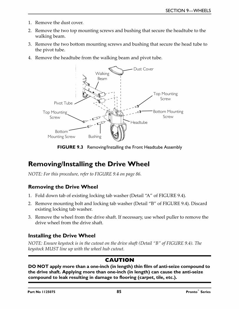
SECTION 9—WHEELS
1. Remove the dust cover.
2. Remove the two top mounting screws and bushing that secure the headtube to the walking beam.
3. Remove the two bottom mounting screws and bushing that secure the head tube to the pivot tube.
4. Remove the headtube from the walking beam and pivot tube.
FIGURE 9.3 Removing/Installing the Front Headtube Assembly
Removing/Installing the Drive WheelNOTE: For this procedure, refer to FIGURE 9.4 on page 86.
Removing the Drive Wheel
1. Fold down tab of existing locking tab washer (Detail “A” of FIGURE 9.4).
2. Remove mounting bolt and locking tab washer (Detail “B” of FIGURE 9.4). Discard existing locking tab washer.
3. Remove the wheel from the drive shaft. If necessary, use wheel puller to remove the drive wheel from the drive shaft.
Installing the Drive WheelNOTE: Ensure keystock is in the cutout on the drive shaft (Detail “B” of FIGURE 9.4). The keystock MUST line up with the wheel hub cutout.
CAUTIONDO NOT apply more than a one-inch (in length) thin film of anti-seize compound to the drive shaft. Applying more than one-inch (in length) can cause the anti-seize compound to leak resulting in damage to flooring (carpet, tile, etc.).
Top Mounting Screw
Dust Cover
Bushing
Headtube
Top Mounting Screw
Bottom Mounting Screw
Bottom Mounting Screw
Walking Beam
Pivot Tube
Part No 1125075 85 Pronto® Series

SECTION 9—WHEELS
1. Apply an anti-seize compound to drive shaft and keystock.
2. Align the keystock in the drive shaft with the cutout in the wheel hub and position the wheel on to the drive shaft (Detail “B” of FIGURE 9.4).
� WARNINGFailure to properly install locking tab washer can result in wheel separation and potential user injury or property damage. When replacing wheels ALWAYS use a new locking tab washer. DO NOT reuse locking tab washers.
NOTE: The locking tab of the locking tab washer MUST be inserted into the cutout in the rim and hub (Detail “B” of FIGURE 9.4).
3. Using the mounting bolt, washer and new locking tab washer, secure the wheel to the drive shaft (Detail “B” of FIGURE 9.4).
4. Fold one tab of the locking tab washer up so that the tab rests against one side of the mounting bolt (Detail “A” of FIGURE 9.4)
FIGURE 9.4 Removing/Installing the Drive Wheel
Replacing the 2-Piece Wheel Rim and/or the Foam Filled or Pneumatic Tires NOTE: For this procedure, refer to FIGURE 9.5 on page 87.
NOTE: When replacing the 2-piece wheel rim, DO NOT remove tire. Replacement 2-piece wheel rims are shipped assembled with a new tire. Refer to Removing/Installing the Drive Wheel on page 85 to remove the existing and install the new 2-piece wheel rim and tire.
DETAIL “A” DETAIL “B”
Locking Tab Washers (Tabs)
Locking Tab Washer (Tab)
Mounting Bolt
Mounting Bolt
NOTE: Locking tab washer shown with all tabs folded down to remove/install the mounting bolt.
NOTE: Locking tab washer shown with one tab folded up to secure the mounting bolt.
Mounting Bolt
Drive Shaft
Motor and Gearbox
Washer
Keystock
Wheel
Outer Rim Cutout
Locking Tab
Locking Tab Washer
Pronto® Series 86 Part No 1125075

SECTION 9—WHEELS
� WARNINGWhen replacing the hub of a pneumatic tire, ALWAYS deflate tire before removing/installing hub - otherwise, injury or damage may occur. Failure to observe this warning can result in sudden, violent rim separation and possible injury.
1. Deflate existing pneumatic tire.
2. Remove the four existing mounting screws, locknuts and washers that secure the existing outer rim and inner rim.
3. Separate the two halves of the rim and remove the existing tire. Discard existing tire.
NOTE: When installing the new pneumatic tire, if necessary, place the inner tube into the tire.
NOTE: When installing the outer rim into a pneumatic tire ensure the valve stem of the inner tube protrudes through the stem opening in the outer rim.
4. Insert the outer rim and inner rim into the new/existing tire.
5. Insert the hub into the inner rim and align the four mounting holes of the hub, inner rim and outer rim.
6. Using the four mounting screws, lock washers and hex nuts, secure the outer rim to the inner rim and hub. Torque hex nuts to 160 - 200-inch-lbs.
7. If pneumatic, fill tire to correct air pressure as noted on tire side wall.
FIGURE 9.5 Replacing the 2-Piece Wheel Rim and/or the Foam Filled or Pneumatic Tires
Inner Rim
Outer Rim
Tire
Wheel Hub Cutout
WashersLocknuts
Mounting ScrewsHub
Part No 1125075 87 Pronto® Series

SECTION 10—SHROUDS AND FRAME
SECTION 10—SHROUDS AND FRAME
� WARNINGAfter any adjustments, repair or service and before use, make sure that all attaching hardware is tightened securely - otherwise injury or damage may result.Before performing any maintenance, adjustment or service verify that On/Off switch on the joystick is in the Off position.To prevent cracking the plastic shroud material, DO NOT overtighten the mounting screws.
Removing/Installing the Top ShroudNOTE: For this procedure, refer to FIGURE 10.1 on page 89.
Removing
1. Disconnect the joystick. Refer to Disconnecting/Connecting the Joystick on page 124.
2. M61 Wheelchairs Only - Remove the joystick cable from the clip on the top shroud.
3. Remove the seat. Refer to Removing/Installing the Seat Assembly on page 50.
4. Remove the top shroud by pulling it up off the base frame.
Installing
1. Pull joystick cable through the center hole in the top shroud.
2. Place the top shroud on the base frame and push downward to engage the hook and loop straps.
3. M61 Wheelchairs Only - Secure the joystick cable using the clip on the top shroud.
4. Install the seat assembly. Refer to Removing/Installing the Seat Assembly on page 50.
5. Connect the joystick. Refer to Disconnecting/Connecting the Joystick on page 124.
Pronto® Series 88 Part No 1125075

SECTION 10—SHROUDS AND FRAME
FIGURE 10.1 Removing/Installing the Top Shroud
Removing/Installing the Side ShroudsNOTE: For this procedure, refer to FIGURE 10.2 on page 90.
Removing
1. Remove the two screws securing the side shroud to the frame.
2. Remove the side shroud from the frame.
Installing
1. Position the side shroud onto the frame.
2. Align the shroud mounting holes with the mounting holes in the frame.
3. Secure the side shroud to the frame using the two screws. DO NOT overtighten.
Top Shroud
Front Shroud
Base Frame
Hook and Loop Strap
Hook and Loop Strap
Joystick Cable and Connector
Center Hole in
Top Shroud
NOTE: Batteries not shown for clarity.
DETAIL “A” - M61 TOP SHROUD
Clip
Part No 1125075 89 Pronto® Series

SECTION 10—SHROUDS AND FRAME
FIGURE 10.2 Removing/Installing the Side Shrouds
Removing/Installing the Front ShroudNOTE: For this procedure, refer to FIGURE 10.3 on page 91.
Removing
1. Remove the two screws securing the top of the front shroud to the frame.
2. Remove the front shroud fo the frame.
Installing
1. Insert the tabs at the bottom of the front shroud into the slots in the bottom of the frame.
2. Secure the top of the front shroud to the frame using the two screws. DO NOT overtighten.
Side Shroud
ScrewsShroud Mounting Holes
Frame
Pronto® Series 90 Part No 1125075

SECTION 10—SHROUDS AND FRAME
FIGURE 10.3 Removing/Installing the Front Shroud
Removing/Installing the Inner ShroudsNOTE: For this procedure, refer to FIGURE 10.4 on page 92.
Removing
1. Remove the walking beam. Refer to Removing/Installing the Walking Beam on page 94.
2. Remove the large screw and locknut securing the inner shroud to the walking beam.
3. Remove the small screw securing the the inner shroud to the side shroud (if present).
4. Remove the inner shroud.
Installing
1. Position the inner shroud on the walking beam.
2. Use the small screw to secure the inner shroud to the side shroud. DO NOT overtighten.
3. Insert the large screw through the large mounting hole in the inner shroud and the walking beam.
4. Use the locknut to secure the inner shroud to the walking beam. DO NOT overtighten.
5. Install the walking beam. Refer to Removing/Installing the Walking Beam on page 94.
Front Shroud
Screw
Screw
Tabs
Slots
Frame
Part No 1125075 91 Pronto® Series

SECTION 10—SHROUDS AND FRAME
FIGURE 10.4 Removing/Installing the Inner Shrouds
Removing/Installing the Pivot TubeNOTE: For this procedure, refer to FIGURE 10.5 on page 93.
Removing
1. Remove the front headtube assembly. Refer to Removing/Installing the Front Headtube Assembly on page 84.
2. Remove the side shroud. Refer to Removing/Installing the Side Shrouds on page 89.
3. remove the locknut, two small washers and large washer securing the rear of the pivot tube to the threaded post.
4. Remove the pivot tube from the frame.
NOTE: The front and rear bushings may fall out of the pivot tube when it is removed. Retain these for installation.
Side Shroud
Walking Beam
Inner Shroud
Large Screw
Small ScrewLarge
Mounting Hole
Small Mounting
Hole
Pronto® Series 92 Part No 1125075

SECTION 10—SHROUDS AND FRAME
Installing
1. If necessary, insert one bushing into each end of the pivot tube.
2. Position the pivot tube onto the pivot post.
NOTE: Ensure the opposite end of the pivot tube is parallel to the end of the walking beam. If necessary, reposition the pivot tube.
3. Secure the end of the pivot tube to the pivot post using the two small washers, the large washer and the locknut. Torque to 90 in-lbs ± 20%.
4. Install the front headtube assembly. Refer to Removing/Installing the Front Headtube Assembly on page 84.
FIGURE 10.5 Removing/Installing the Pivot Tube
Small Washers
Locknut
Large Washer
Bushings
Pivot Tube
Pivot Post
Walking Beam
Part No 1125075 93 Pronto® Series

SECTION 10—SHROUDS AND FRAME
Removing/Installing the SureStep SpringNOTE: For this procedure, refer to FIGURE 10.6.
Removing
1. Unhook the SureStep spring from the hooks on the walking beam and the frame.
Installing
1. Position the SureStep spring on the hook on the frame.
2. Position the top of the SureStep spring onto the hook on the walking beam.
FIGURE 10.6 Removing/Installing the SureStep Spring
Removing/Installing the Walking BeamNOTE: For this procedure, refer to FIGURE 10.7 on page 95.
Removing
1. Remove the front headtube assembly. Refer to Removing/Installing the Front Headtube Assembly on page 84.
2. Unhook the top of the SureStep spring from the hook on the walking beam.
3. Remove the shoulder screw and locknut securing the walking beam to the frame bracket.
4. Remove the walking beam from the frame.
Installing
1. Position the walking beam into the frame bracket.
2. Secure the walking beam to the frame using the shoulder screw and locknut. Torque to 23 ft-lbs ± 20%.
Hook
SureStep Spring
HookWalking Beam
Frame
Pronto® Series 94 Part No 1125075

SECTION 10—SHROUDS AND FRAME
3. Hook the top of the SureStep spring to the hook on the walking beam.
4. Install the front headtube assembly. Refer to Removing/Installing the Front Headtube Assembly on page 84.
FIGURE 10.7 Removing/Installing the Walking Beam
Removing/Installing the Elevate ActuatorNOTE: For this procedure, refer to FIGURE 10.8 on page 97.
NOTE: This procedure applies to M61 wheelchairs only.
Removing
1. Remove the seat. Refer to one of the following procedures:
• Van Seats - Refer to Removing/Installing the Seat Assembly on page 50.
• ASBA Seats - Refer to Removing/Installing the Seat Assembly on page 59.
2. Remove the batteries. Refer to Removing/Installing Batteries from/into Battery Tray on page 100.
3. Disconnect the actuator connector from the controller connector (Detail “A”).
4. Cut the three tie-wraps securing the actuator cable to the frame (Detail “A”).
5. Remove the four hex screws and washers securing the elevate actuator to the bottom of the frame.
6. Remove the four button screws and washers securing the elevate actuator to the top of the frame.
7. Remove the two screws and small washers securing the actuator switch sensor to the elevate actuator.
Locknut
Shoulder Screw
SureStep SpringWalking Beam
Hook
Frame Bracket
Part No 1125075 95 Pronto® Series

SECTION 10—SHROUDS AND FRAME
Installing
1. Secure the actuator switch sensor to the elevate actuator using the two screws and small washers. Tighten securely.
2. Secure the elevate actuator to the top of the frame using the four button screws and washers. Torque to 75 in-lbs ± 20%.
3. Secure the elevate actuator to the bottom of the frame using the four hex screws and washers. Torque to 75 in-lbs ± 20%.
4. Connect the actuator connector to the controller connector (Detail “A”).
5. Secure the cables to the frame using three tie-wraps in the locations shown in Detail “A”.
6. Install the batteries. Refer to Removing/Installing Batteries from/into Battery Tray on page 100.
7. Install the seat. Refer to one of the following procedures:
• Van Seats - Refer to Removing/Installing the Seat Assembly on page 50.
• ASBA Seats - Refer to Removing/Installing the Seat Assembly on page 59.
Pronto® Series 96 Part No 1125075

SECTION 10—SHROUDS AND FRAME
FIGURE 10.8 Removing/Installing the Elevate Actuator
Hex Screw
Washer
Frame
Actuator Mounting Holes
Button Screw
Washer
ScrewActuator Switch
Sensor
Small Washer
Elevate Actuator
Washer
Button Screw
DETAIL “A” - WIRE ROUTING Tie-Wraps Actuator
Connector
Controller Connector
Part No 1125075 97 Pronto® Series

SECTION 10—SHROUDS AND FRAME
Removing/Installing the Actuator Switch SensorNOTE: For this procedure, refer to FIGURE 10.8 on page 97.
NOTE: This procedure applies to M61 wheelchairs only.
Removing
1. Elevate the seat. Refer to Elevating the Seat on page 38.
2. Remove the seat. Refer to one of the following procedures:
• Van Seats - Refer to Removing/Installing the Seat Assembly on page 50.
• ASBA Seats - Refer to Removing/Installing the Seat Assembly on page 59.
3. Remove the batteries. Refer to Removing/Installing Batteries from/into Battery Tray on page 100.
4. Remove the two screws and small washers securing the actuator switch sensor to the elevate actuator.
Installing
1. Secure the actuator switch sensor to the elevate actuator using the two screws and small washers. Tighten securely.
2. Install the batteries. Refer to Removing/Installing Batteries from/into Battery Tray on page 100.
3. Install the seat. Refer to one of the following procedures:
• Van Seats - Refer to Removing/Installing the Seat Assembly on page 50.
• ASBA Seats - Refer to Removing/Installing the Seat Assembly on page 59.
Pronto® Series 98 Part No 1125075

SECTION 11—BATTERIES
SECTION 11—BATTERIESWarnings For Handling and Replacing Batteries
� DANGERRisk of Death or Serious InjuryFailure to observe these warnings can cause an electrical short resulting in death, serious injury, or damage to the electrical system.
The POSITIVE (+) RED battery cable MUST connect to the POSITIVE (+) battery terminal(s)/post(s). The NEGATIVE (-) BLACK battery cable MUST connect to the NEGATIVE (-) battery terminal(s)/post(s). NEVER allow any of your tools and/or battery cable(s) to contact BOTH battery post(s) at the same time. An electrical short may occur and serious injury or damage may occur.Install protective caps on positive and negative battery terminals.Replace cable(s) immediately if cable(s) insulation becomes damaged. DO NOT remove fuse or mounting hardware from POSITIVE (+) red battery cable mounting screw.
� WARNINGAfter any adjustments, repair or service and before use, make sure that all attaching hardware is tightened securely - otherwise injury or damage may result.Make sure power to the wheelchair is Off before performing this section.The use of rubber gloves is recommended when working with batteries.Invacare strongly recommends that battery installation and battery replacement ALWAYS be done by a qualified technician.U1 batteries weigh 24 pounds each. Use proper lifting techniques (lift with your legs) to avoid injury.Use U1 batteries only. Failure to use the correct battery size and/or voltage may cause damage to your wheelchair and give you unsatisfactory performance.ALWAYS use a battery handle/lifting strap when lifting a battery. It is the most convenient method and assures that the battery acid will not spill. It also helps to prolong the life of the battery.DO NOT tip the batteries. Keep the batteries in an upright position.
Connect same color connectors to each other (RED to RED, BLACK to BLACK).
NOTE: If there is battery acid in the bottom of the battery tray or on the sides of the battery, apply baking soda to these areas to neutralize the battery acid. Before reinstalling the existing or new battery, clean the baking soda from the battery tray or battery being sure to avoid contact with skin and eyes. Determine source of contamination. NEVER install/reinstall a battery with a cracked or otherwise damaged case.
Part No 1125075 99 Pronto® Series
SECTION 11—BATTERIES
Using the Proper BatteriesNOTE: For this procedure, refer to FIGURE 11.1.
1. Place battery on ground/flat surface.
2. Visually draw a horizontal and vertical centerline through the middle of battery (FIGURE 11.1).
3. Position the battery so that the terminals are above the horizontal centerline.
4. Visually inspect the battery to ensure the correct position of the POSITIVE and NEGATIVE terminals (FIGURE 11.1).
� WARNINGBatteries with terminal configuration as shown below MUST be used. Batteries that have the reverse terminal configuration MUST NOT be used - otherwise injury and damage may occur.
FIGURE 11.1 Using the Proper Batteries
Removing/Installing Batteries from/into Battery Tray
� WARNINGALWAYS use the battery handle when lifting the battery. It is the most convenient method and assures that the battery acid will not spill. It also helps to prolong the life of the battery.
DO NOT tip the batteries. Keep the batteries in an upright position.
DO NOT Use
POSITIVE (+) Battery Terminal
U1 BatteryU1 Battery POSITIVE (+)
Battery Terminal
NEGATIVE (-) Battery Terminal
Use This Configuration
NEGATIVE (-) Battery Terminal
Pronto® Series 100 Part No 1125075

SECTION 11—BATTERIES
NOTE: For this procedure, refer to FIGURE 11.2 on page 102.
NOTE: If there is battery acid in the bottom of the battery tray or on the sides of the battery, apply baking soda to these areas to neutralize the battery acid. Before reinstalling the existing or new battery, clean the baking soda from the battery tray or battery being sure to avoid contact with skin and eyes. Determine source of contamination. NEVER install/reinstall a battery with a cracked or otherwise damaged case.
NOTE: Have the following tools available:
Removing
1. Place the wheelchair in a well ventilated area where work can be performed without risking damage to carpeting or floor covering.
2. Verify the joystick On/Off switch is in the Off position and disconnect joystick cable (not shown). Refer to Disconnecting/Connecting the Joystick on page 124.
3. Remove the seat. Refer to one of the following procedures:
• Van Seats - Refer to Removing/Installing the Seat Assembly on page 50.
• ASBA Seats - Refer to Removing/Installing the Seat Assembly on page 59.
4. Remove the top shroud. Refer to Removing/Installing the Top Shroud on page 88.
5. Disconnect the front battery from the controller (BLACK connector).
6. Disconnect the rear battery from the front battery (RED and BLACK connectors).
7. Lift rear and front battery out of the battery tray using the battery handles.
Installing
1. Verify the joystick On/Off switch is in the Off position and disconnect joystick cable. Refer to Disconnecting/Connecting the Joystick on page 124.
2. Position the front battery in the front of the battery tray.
3. Position rear battery in rear of battery tray.
NOTE: Ensure that both batteries are properly seated and resting on the battery tray.
4. Connect the rear battery to the front battery (RED and BLACK connectors).
5. Connect the front battery to the controller (BLACK connector).
6. Reinstall the top shroud. Refer to Removing/Installing the Top Shroud on page 88.
7. Reinstall the seat. Refer to one of the following procedures:
• Van Seats - Refer to Removing/Installing the Seat Assembly on page 50.
• ASBA Seats - Refer to Removing/Installing the Seat Assembly on page 59.
TOOL QTY COMMENTS7/16-INCH (6PT) BOX WRENCH 1 Not Supplied
DIAGONAL CUTTERS 1 Not Supplied
Part No 1125075 101 Pronto® Series

SECTION 11—BATTERIES
8. Connect joystick cable (not shown). Refer to Disconnecting/Connecting the Joystick on page 124.
FIGURE 11.2 Removing/Installing Batteries from/into Battery Tray
Connecting/Disconnecting Battery Cables
Connecting Battery Cables
� WARNINGNEVER allow any of your tools and/or battery cables to contact both battery terminals at the same time. An electrical short may occur and serious personal injury or damage may occur.Connect same color connectors to each other (RED to RED, BLACK to BLACK).DO NOT remove fuse or mounting hardware from POSITIVE (+) battery cable mounting screw. To replace the fuse, obtain and replace battery harness with fuse.The POSITIVE (+) battery cable MUST connect to the POSITIVE (+) battery terminal, otherwise serious damage will occur to the electrical system.The use of rubber gloves is recommended when working with batteries.
Rear Battery
Front Battery
RED Battery Connectors
Plug into Controller
BLACK Battery Connectors
Rear of Wheelchair
Front of Wheelchair
Wheelchair Base Frame
Top Shroud
Battery Handle
BLACK Controller Connector
Joystick Cable
Pronto® Series 102 Part No 1125075

SECTION 11—BATTERIES
� WARNINGBattery terminal configuration as shown in Detail “A” of FIGURE 11.3 MUST be used. Batteries that have the terminal configuration reversed MUST NOT be used - otherwise serious injury or damage may occur.Install protective caps on POSITIVE (+) and NEGATIVE (-) terminals.
All battery terminal covers (two on the front battery and two on the rear battery) MUST be installed prior to use.
CAUTIONWhen connecting the battery cables to the battery, the battery cables MUST be connected to the battery terminals, as shown in Detail “A” of FIGURE 11.3 (depending on battery type), otherwise damage to the battery cable may result when installing battery terminal caps.
NOTE: For this procedure, refer to FIGURE 11.3 on page 104.
1. Secure the battery cables to the battery terminals as described below. Securely tighten. Refer to Detail “A” of FIGURE 11.3:
A. Secure NEGATIVE (-) battery cable to the NEGATIVE (-) battery terminal using the mounting screw and the locknut.
B. Secure the POSITIVE (+) battery cable to the POSITIVE (+) battery terminal using the L-bracket with mounting screw and the locknut.
2. Verify all battery cables are correctly installed and securely tightened.
3. Slide terminal caps down battery cables and onto battery terminals.
4. Secure each terminal cap in place with a tie-wrap [use tie-wraps 11-1/2-inches long] (Detail “B” of FIGURE 11.3).
5. Position the batteries into the wheelchair. Refer to Removing/Installing Batteries from/into Battery Tray on page 100.
NOTE: New batteries MUST be fully charged before using, otherwise the life of the batteries will be reduced.
6. If necessary, charge the battery. Refer to Charging Batteries on page 105.
Part No 1125075 103 Pronto® Series

SECTION 11—BATTERIES
FIGURE 11.3 Connecting/Disconnecting Battery Cables
RED Connectors
POSITIVE (+) Battery Cable
POSITIVE (+) Battery terminal
NEGATIVE (-) Battery Cable
NEGATIVE (-) Battery Terminal
Cap
NEGATIVE (-) Battery terminal
Locknuts
U1 Battery
POSITIVE (+) Battery Terminal Cap
DETAIL “A”
DETAIL “B”
NOTE: Handles on batteries removed for clarity.
POSITIVE (+) Battery Terminal
NEGATIVE (-) Battery Terminal
Tie-wrapsU1 Battery
U1 Batteries
BLACK Connectors
BLACK Connector to
Controller
Plug into controller
NOTE: Handles on batteries removed for clarity.
RED Connectors
Mounting Screw
L-Bracket with Mounting Screw
BLACK Connectors
NOTE: Battery terminal caps not shown on front battery for clarity.
Pronto® Series 104 Part No 1125075

SECTION 11—BATTERIES
Disconnecting Battery Cables
� WARNINGThe use of rubber gloves is recommended when working with batteries.NEVER allow any of your tools and/or battery cables to contact both battery terminals at the same time. An electrical short may occur and serious personal injury or damage may occur.
NOTE: For this procedure, refer to FIGURE 11.3 on page 104.
1. Remove the seat. Perform one of the following:
• Van Seat - Refer to Removing/Installing the Seat Assembly on page 50.
• ASBA Seat - Refer to Removing/Installing the Seat Assembly on page 59.
2. Remove the batteries. Refer to Removing/Installing Batteries from/into Battery Tray on page 100.
3. Cut the tie-wrap that secures the battery terminal cap in place (Detail “B” of FIGURE 11.3).
4. Slide terminal caps up onto the battery cables (FIGURE 11.3).
5. Disconnect POSITIVE (+) battery cable from the POSITIVE (+) battery terminal (FIGURE 11.3).
6. Disconnect NEGATIVE (-) battery cable from NEGATIVE (-) battery terminal (FIGURE 11.3).
Charging Batteries
� WARNINGNEVER attempt to recharge the batteries by attaching cables directly to the battery terminals. DO NOT attempt to recharge the batteries and operate the wheelchair at the same time.DO NOT attempt to recharge the batteries when the wheelchair has been exposed to any type of moisture.DO NOT attempt to recharge the batteries when the wheelchair is outside.DO NOT sit in the wheelchair while recharging the batteries.DO NOT attempt to recharge the batteries using both the on-board battery charger and an independent battery charger (plugged into the joystick charger port) at the same time. Doing so will reduce the life of the batteries. Read and carefully follow the individual instructions for each charger (supplied or purchased). If charging instructions are not supplied, consult a qualified technician for proper procedures.
Part No 1125075 105 Pronto® Series

SECTION 11—BATTERIES
CAUTIONNew batteries MUST be fully charged prior to initial use of the wheelchair.ALWAYS charge new batteries before initial use or battery life will be reduced. As a general rule, you should recharge your batteries as frequently as possible to assure the longest possible life and to minimize required charging time. Plan to recharge them when you do not anticipate using the wheelchair.
Basic concepts which will help you understand this automatic process are:
The amount of electrical current drawn within a given time to charge a battery is called “charge rate”. If, due to usage, the charge stored in the battery is low, the charge rate is high. As a charge builds up, the charge rate is reduced, and the battery charger rate decreases to a “trickle charge”.NOTE: If the batteries need to be charged more often or take longer to charge than normal, they may need to be replaced. Contact a qualified technician.
NOTE: The batteries can be charged using the on-board battery charger or by plugging an independent battery charger into the port located on the front of the joystick.
Battery Charger Operation
� WARNINGRead and carefully follow the manufacturer’s instructions for each charger (supplied or purchased). If charging instructions are not supplied, consult a qualified technician for proper procedures.NEVER leave the charger unattended when the charger circuit breaker is tripping.
� DANGERUse of improper extension cord could result in risk of fire and electric shock.
Pronto® Series 106 Part No 1125075

SECTION 11—BATTERIES
On-Board Battery Charger
� DANGERWhen using an extension cord, use only a three wire extension cord having at least 16 AWG (American Wire Gauge) wire and the same or higher electrical rating as the device being connected. Use of improper extension cord could result in risk of fire and electric shock. Three prong to two prong adapters should not be used. Use of three prong adapters can result in improper grounding and present a shock hazard to the user.
� WARNINGEnsure the pins of the extension cord plug are the same number, size, and shape as those on the charger.DO NOT, under any circumstances, cut or remove the round grounding plug from the charger AC cable plug or the extension cord plug.
NOTE: For this procedure, refer to FIGURE 11.4 on page 108.
NOTE: The On/Off LED indicator light and the charger LED indicator light are located on the top of the charger on the rear of the wheelchair. Open rear shroud to view indicator lights.
NOTE: If the batteries are completely discharged, the charger will not charge them. Replace the batteries. Refer to Removing/Installing Batteries from/into Battery Tray on page 100.
1. Plug the female connector of the AC power cord (supplied) to the AC receptacle on the charger and plug in the male connector on the AC power cord into the wall outlet.
2. The On/Off LED indicator is blinking RED, this is abnormal. Unplug AC power cord from the on-board battery charger and wall outlet. Charger may need to be replaced. Refer to Replacing the On-Board Battery Charger Fuse on page 109.
3. When the On/Off LED indicator light is Off, charger is Off.
4. When the Charge LED indicator light is YELLOW, the batteries are charging.
5. When the Charge LED indicator light is solid GREEN, the batteries are fully charged (as their condition will allow).
6. When charging is complete, unplug the male connector of the AC power cord from the wall outlet and then unplug the female connector of the AC power cord from the AC receptacle on the charger.
� WARNINGDO NOT operate wheelchair with AC power cord attached to the wheelchair.
Part No 1125075 107 Pronto® Series

SECTION 11—BATTERIES
FIGURE 11.4 On-Board Battery Charger
Charging Using An Independent Charger Plugged Into The Joystick
� WARNINGRead and carefully follow the individual instructions for each charger (supplied or purchased). If charging instructions are not supplied, consult a qualified technician for proper procedures.DO NOT attempt to recharge the batteries using both the on-board battery charger and an independent battery charger (plugged into the joystick charger port) at the same time. Doing so will reduce the life of the batteries.
CAUTIONOnly use a charger approved by Invacare when charging through the joystick on this wheelchair model.DO NOT use an independent charger with an output rating of over 8A (Amps). Otherwise, damage may occur.
ON/OFF INDICATOR STATUSSOLID RED Charger On
“BLINKING” RED Abnormal
LED “OFF” Charger Off
CHARGING INDICATOR STATUS
YELLOW Charging
SOLID GREEN Fully charged
Charger(Hidden from View)
AC Receptacle on Charger
Male Connector on AC Power
Cord (Connects to Wall Outlet)
Female Connector on AC Power Cord (Connects to AC
Receptacle on Charger)
To Wall Outlet
Pronto® Series 108 Part No 1125075

SECTION 11—BATTERIES
NOTE: For this procedure, refer to FIGURE 11.5.
NOTE: The charger port located on the front of the joystick requires the use of an independent charger. The independent charger is NOT supplied with the wheelchair.
1. Attach the battery charger connector to the charger port on the front of the joystick.
2. Plug the charger’s AC power cord or extension into the grounded 110-volt wall outlet.
3. When charging is complete, turn charger Off.
4. Disconnect output cable from joystick charger port.
FIGURE 11.5 Charging Using An Independent Charger Plugged Into The Joystick
Replacing the On-Board Battery Charger Fuse
� WARNINGDO NOT replace the battery charger fuse with anything other than a 250V 47 Amp fuse. Otherwise, equipment damage and/or personnel injury may occur.DO NOT attempt to remove the battery charger fuse with power applied to the wheelchair. Otherwise, equipment damage and/or personnel injury may occur.
NOTE: For this procedure, refer to FIGURE 11.6 on page 110.
NOTE: The output of the battery charger is fused with a 250V, 4 amp fuse. The fuse holder is located on the left side of the charger as it is mounted to the wheelchair. This fuse should be checked first before replacing the battery charger for improper operation. If it has been determined the charger should be replaced. Refer to Replacing the On-Board Battery Charger on page 110.
NOTE: If the batteries are completely discharged, the charger will not charge them. Replace the batteries. Refer to Removing/Installing Batteries from/into Battery Tray on page 100.
1. Turn Off power and disconnect joystick. Refer to Disconnecting/Connecting the Joystick on page 124.
2. Remove top shroud. Refer to Removing/Installing the Top Shroud on page 88.
Independent Charger Port (Charger NOT supplied)
Part No 1125075 109 Pronto® Series

SECTION 11—BATTERIES
3. Remove the fuse holder from left side of charger next to battery charger cable and perform one of the following:
• If fuse is bad, replace with new 250V, 4 amp fuse.
• If fuse is good, replace charger. Refer to Replacing the On-Board Battery Charger on page 110.
4. Connect joystick and turn power On. Refer to Disconnecting/Connecting the Joystick on page 124.
5. Perform one of the following:
• If wheelchair functions, install top shroud. Refer to Removing/Installing the Top Shroud on page 88.
• If wheelchair does not function, replace charger. Refer to Replacing the On-Board Battery Charger on page 110.
FIGURE 11.6 Replacing the On-Board Battery Charger Fuse
Replacing the On-Board Battery Charger
� WARNINGDO NOT replace the battery charger fuse with anything other than a 250V 4 Amp fuse. Otherwise, equipment damage and/or personnel injury may occur.DO NOT attempt to remove the battery charger with power applied to the wheelchair. Otherwise, equipment damage and/or personnel injury may occur.
NOTE: For this procedure, refer to FIGURE 11.7 on page 112.
NOTE: Take note of position and orientation of battery charger cables and tie-wraps for reinstallation.
NOTE: The output of the battery charger is fused with a 250V, 4 amp fuse. The fuse holder is located at the left side of the charger as it is mounted to the wheelchair. This fuse should be checked
Fuse Holder with 250V, 4 amp Fuse
Charger
Battery Charger Cable
Pronto® Series 110 Part No 1125075

SECTION 11—BATTERIES
first before replacing the battery charger for improper operation. Refer to Replacing the On-Board Battery Charger Fuse on page 109.
1. Remove the top shroud. Refer to Removing/Installing the Top Shroud on page 88.
2. Remove the rear battery from the wheelchair. Refer to Removing/Installing Batteries from/into Battery Tray on page 100.
3. Disconnect the battery charger connector (Detail “B”) from the controller connector (not shown).
NOTE: The battery charger is secured to the frame with two hook and loop strips (Detail “B”).
4. Remove the four tie-wraps securing the battery charger connector cable to the wheelchair frame (Detail “A”).
5. Remove the two screws and locknuts securing the battery charger plug to the bracket (Detail “B”).
6. Pull existing charger away from wheelchair frame to release the hook and loop strips and remove the existing charger from the wheelchair frame (Detail “B”).
7. Remove the hook and loop strips from the underside of the existing charger.
8. Install the hook and loop strips onto the underside of the new charger.
9. Place the new battery charger against the wheelchair frame, ensuring that the hook and loop strips properly engage.
10. Secure the battery charger plug to the bracket using the two screws and locknuts. Torque to 75 in-lbs.
11. Route the battery charger connector cable to the right side (from the rear of the wheelchair) of the battery charger body (Detail “B”).
12. Connect the battery charger connector (Detail “B”) to the controller connector .
13. Using four tie-wraps, secure the charger cable to the wheelchair frame (Detail “A”).
14. Install the rear battery. Refer to Removing/Installing Batteries from/into Battery Tray on page 100.
15. Install the top shroud. Refer to Removing/Installing the Top Shroud on page 88.
16. Test the on-board charger for proper operation by performing the following steps:
A. Connect the battery charger to an outlet.
B. Locate pins 1 and 2 in the joystick charger port at the front of the joystick housing (Detail “C”).
C. Use a digital multimeter to check the voltage at pins 1 and 2.
NOTE: Voltage should start to increase after 30 seconds. This indicates that the batteries are being charged.
Part No 1125075 111 Pronto® Series

SECTION 11—BATTERIES
FIGURE 11.7 Replacing the On-Board Battery Charger
Battery Charger
Battery Charger
Connector Cable
Tie-WrapsHook
and Loop Strip
DETAIL “A” DETAIL “B”
Battery Charger Plug
Locknut
Screws
Locknut
Battery Charger
Connector Cable
Battery Charger
Connector
Bracket
Pin 1Pin 2
Front of SPJ JoystickDETAIL “C” - TESTING VOLTAGE
Joystick Charger
Port
Front of SPJ+ or SPJ+ w/ACC Joystick
Pronto® Series 112 Part No 1125075

SECTION 12—MOTORS
SECTION 12—MOTORS� WARNING
After ANY adjustments, repair or service and before use, make sure that all attaching hardware is tightened securely.ALWAYS turn the wheelchair power Off before repairing or servicing the wheelchair, otherwise injury or damage may occur.
Removing/Installing the MotorNOTE: For this procedure, refer to FIGURE 12.1 on page 114.
NOTE: Reverse this procedure to install the motor.
NOTE: Removing walking beam from the wheelchair, while not necessary, may improve access to the motor. Refer to Removing/Installing the Walking Beam on page 94.
1. Remove the seat. Refer to one of the following procedures:
• Van Seats - Refer to Removing/Installing the Seat Assembly on page 50.
• ASBA Seats - Refer to Removing/Installing the Seat Assembly on page 59.
2. Remove the front battery. Refer to Removing/Installing Batteries from/into Battery Tray on page 100.
3. Remove the drive wheel. Refer to Removing/Installing the Drive Wheel on page 85.
4. Remove the side shroud. Refer to Removing/Installing the Side Shrouds on page 89.
5. Remove the front shroud. Refer to Removing/Installing the Front Shroud on page 90.
6. Cut all tie-wraps securing the motor lead to the frame.
7. Disconnect the motor lead connector from the controller (Detail “A”).
8. Remove the cotter pin to disconnect the motor release lever. Refer to Removing/Installing the Motor Release Lever on page 116.
9. Using a 5 mm ball head 10-inch T-handle allen wrench, remove the three long mounting screws and three short mounting screws securing the motor to the walking beam (FIGURE 12.1).
NOTE: Long mounting screws are used on the same side of the motor as the drive shaft.
10. Remove the motor from the walking beam.
11. Position the new motor against the walking beam.
12. Loosely install all screws except the front inside short screw.
13. Install the front inside short screw.
14. Tighten the three long screws and three short screws.
15. If necessary, repeat STEPS 3-14 for the motor on the other side.
Part No 1125075 113 Pronto® Series

SECTION 12—MOTORS
16. Reverse STEPS 1 - 8 to reassemble the base.
FIGURE 12.1 Removing/Installing the Motor
Three Short and Three Long Mounting
Screws
Motor
NOTE: Drive wheel shown exploded from the motor drive shaft for clarity.
Drive Wheel
Drive Shaft
Walking Beam
Motor Lead
NOTE: Motor not shown for clarity
DETAIL “A”
Tie-Wraps
Motor Lead Connectors
Controller
Front Inside Short Screw
Pronto® Series 114 Part No 1125075

SECTION 12—MOTORS
Engaging/Disengaging Motor Release Lever
� WARNINGDO NOT engage or disengage the motor release lever until the On/Off switch on the joystick is in the Off position.
CAUTIONEnsure both motor release levers are fully engaged before driving the wheelchair
NOTE: For this procedure, refer to FIGURE 12.2.
NOTE: The motor lock disengagement/engagement allows freewheeling or joystick controlled operation. Freewheeling allows an attendant to maneuver the wheelchair without power.
1. Locate the motor release handles on the motors protruding through the top shroud on the rear of the wheelchair.
2. Perform one (1) of the following:
• To Disengage the Motor Release Levers - Pull the motor lock lever towards the rear of the wheelchair (freewheel position).
NOTE: This allows the chair to freewheel for pushing, if necessary.
NOTE: It may be necessary to rock the wheels slightly until the motor release lever disengages.
• To Engage the Motor Release Levers - Push the motor lock handles towards the front of the wheelchair (drive position).
NOTE: This allows the motors to drive the wheels.
NOTE: It may be necessary to rock the wheels slightly until the motor release lever engages.
FIGURE 12.2 Engaging/Disengaging Motor Release Lever
Disengaged
Right Motor Release Lever
Shown
Engaged
Part No 1125075 115 Pronto® Series
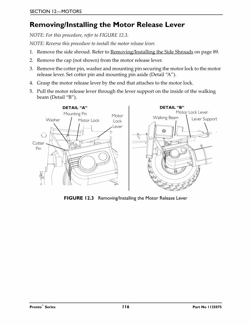
SECTION 12—MOTORS
Removing/Installing the Motor Release LeverNOTE: For this procedure, refer to FIGURE 12.3.
NOTE: Reverse this procedure to install the motor release lever.
1. Remove the side shroud. Refer to Removing/Installing the Side Shrouds on page 89.
2. Remove the cap (not shown) from the motor release lever.
3. Remove the cotter pin, washer and mounting pin securing the motor lock to the motor release lever. Set cotter pin and mounting pin aside (Detail “A”).
4. Grasp the motor release lever by the end that attaches to the motor lock.
5. Pull the motor release lever through the lever support on the inside of the walking beam (Detail “B”).
FIGURE 12.3 Removing/Installing the Motor Release Lever
Mounting PinLever SupportWalking Beam
DETAIL “B”DETAIL “A”
Washer
Cotter Pin
Motor LockMotor Lock Lever
Motor Lock Lever
Pronto® Series 116 Part No 1125075

SECTION 12—MOTORS
Replacing Motor BrushesNOTE: For this procedure, refer to FIGURE 12.4 on page 119.
1. Turn power Off.
2. Disengage motors. Refer to Engaging/Disengaging Motor Release Lever on page 115.
3. Remove the two end cap screws on the end cap. Refer to Detail “A.
4. Remove the end cap and locate the brush assembly on each side of the motor. Refer to Detail “B”.
CAUTIONUse caution when removing the screw and washer that attaches the shunt wire to the motor. DO NOT discard the screw and washer. The screw and washer are not available as service parts.
5. Remove the mounting screw and washer that mounts the shunt wire to the motor assembly. DO NOT discard the mounting screw and washer. Refer to Detail “C” .
CAUTIONWhen removing the existing brushes, ensure that the spring retainer is not removed and/or discarded. The spring retainer is not available as a service part.
6. Release the tension on the brush spring retainer with a small screwdriver and position the screwdriver in place to hold the spring retainer. Refer to Detail “D”.
7. Remove the motor brush and perform the following:
A. Inspect the commutator (not shown) for damage.
B. Inspect the motor brush thoroughly for excessive wear or chips in the brush and any discoloration in the shunt wire and perform one of the following:
• If motor brush is in good condition, (i.e., the end of the brushes are smooth and shiny and shunt wire is not discolored), reinstall existing brush back into brush holder.
• If motor brush is in bad condition, brush is worn or damaged, discard IMMEDIATELY and install new brush into brush holder.
8. Remove the screwdriver to release spring retainer so as to hold brush in place.
9. Attach the shunt wire to the motor housing using the mounting screw and washer (removed in STEP 5). Securely tighten.
10. Replace the motor end cap and secure using the two end cap screws.
NOTE: Repeat STEPS 1-10 for the opposite motor.
Part No 1125075 117 Pronto® Series

SECTION 12—MOTORS
11. If new motor brush was installed, perform the following process:
NOTE: This process, also called Brush Burn-in or Finger Printing Process, is necessary to seat the brush to the commutator plates inside the motor for optimum performance of the motor.
� WARNINGDO NOT leave the wheelchair unattended while performing this procedure - otherwise damage to wheelchair and/or property may occur.
NOTE: This procedure MUST be performed with little or no load on the motor.
A. Put the wheelchair on blocks so that the drive wheels do not contact the ground.
NOTE: For steps B and D, use a rubber band to hold the driver control in the direction needed or program the chair for latched driving. Refer to the electronics manual for latched programming instructions.
B. Run the motors forward for one hour.
C. Turn motors Off and allow 30 minutes for motors to cool off.
D. Run the motors in reverse for one hour.
E. When process is complete, remove wheelchair from blocks and test drive the wheel chair.
NOTE: If wheelchair still does not perform properly, call Technical Service at 1-800-832-4707.
Pronto® Series 118 Part No 1125075

SECTION 12—MOTORS
FIGURE 12.4 Replacing Motor Brushes
Electro-Mechanical Parking Brake Testing NOTE: For this procedure, refer to FIGURE 12.5 on page 120.
NOTE: This procedure should only be performed on wheelchairs with conventional motor/gearbox assembly.
1. Engage the motor release lever. Refer to Engaging/Disengaging Motor Release Lever on page 115.
2. On the four-pin motor connector, locate the side by side connectors in the black housings.
3. Set the digital multimeter to read ohms.
4. Measure the resistance between the two brake contacts.
• A normal reading is between 45-100 ohms depending on the motor.
• A reading of 0 ohms (W) or a very high reading; i.e., MEG ohms or O.L. (out of limit) indicates a shorted brake or an open connection respectively. If either condition exists, send the motor to Invacare Technical Service for inspection/repair.
DETAIL “A” - REMOVE END CAP DETAIL “B” - LOCATE MOTOR BRUSH
DETAIL “D” - REMOVE LARGE BRUSHDETAIL “C” - REMOVE SHUNT WIRE
NOTE: Brush assembly on one side of Motor shown.
End CapEnd Cap Screws
2-Pole DC Motor
Screwdriver to Remove End Cap Screws (STEP 1)
Spring Retainer
Motor Brush
Brush Housing
Shunt Wire
Screwdriver to Remove Shunt Wire
Screw(STEP 4)
Motor Brush
Shunt Wire
Shunt Wire Mounting Screw
Screwdriver to Release Tension on Spring Retainer (STEP 5)
Motor Brush
Shunt Wire
Spring Retainer
Part No 1125075 119 Pronto® Series

SECTION 12—MOTORS
� WARNINGA shorted electro-mechanical brake will damage the brake output section in the controller. DO NOT connect a shorted electro-mechanical brake to a good controller module. A shorted brake MUST be replaced.
NOTE: A bad motor can damage the controller module but a bad controller will NOT damage a motor..
FIGURE 12.5 Electro-Mechanical Parking Brake Testing
4 Pin Motor Connector
Digital Multimeter
Pronto® Series 120 Part No 1125075
SECTION 13—ELECTRONICS
SECTION 13—ELECTRONICS
� WARNINGAfter any adjustments, repair or service and before use, make sure that all attaching hardware is tightened securely - otherwise injury or damage may result.
Before performing any maintenance, adjustment or service verify that On/Off switch on the joystick is in the Off position.
Removing/Installing the JoystickNOTE: For this procedure, refer to FIGURE 13.1 on page 122.
Removing
1. Disconnect the joystick. Refer to Disconnecting/Connecting the Joystick on page 124.
2. Cut the tie-wraps that secure the joystick cable to the arm.
3. Loosen the adjustment lock lever to release the joystick mounting tube from the mounting bracket. Refer to FIGURE 13.1.
4. Remove the joystick and joystick mounting tube from the mounting bracket.
Installing
1. Slide joystick mounting tube through the mounting bracket to the desired position.
2. Tighten the adjustment lock lever to secure the joystick mounting tube to the mounting bracket on the other arm.
3. Tie-wrap the joystick cable to the arm as shown in FIGURE 13.1.
4. Connect the joystick. Refer to Disconnecting/Connecting the Joystick on page 124.
Part No 1125075 121 Pronto® Series

SECTION 13—ELECTRONICS
FIGURE 13.1 Removing/Installing the Joystick
Repositioning the Joystick Mounting Bracket
Van SeatNOTE: For this procedure, refer to FIGURE 13.2 on page 123.
NOTE: Take note of position and orientation of mounting hardware for reinstalling the joystick assembly.
1. Turn the adjustment lock lever to release the joystick mounting tube from the mounting bracket.
2. Remove the joystick from the wheelchair.
3. Remove the three hex mounting screws, spacers and locknuts that secure the mounting bracket to the three mounting holes on the arm frame.
NOTE: The mounting bracket is mounted to the inside of the arm frame.
4. Reposition the mounting bracket on the opposite arm frame.
Joystick
Joystick Mounting
Tube
Mounting Screws
Mounting Bracket and Adjustment Lock Lever
Office Style Seat
Standard Arm
JoystickOffice Style Seat
Joystick Cable
Tie-Wrap Here
Tie-Wrap HereStandard
Arm
DETAIL “A” - TIE-WRAP LOCATIONS
Pronto® Series 122 Part No 1125075

SECTION 13—ELECTRONICS
5. Using the three hex mounting screws, spacers and locknuts secure the mounting bracket to the three mounting holes of the arm frame.
6. If necessary, perform the following to reposition the adjustment lock:
A. Slide the adjustment lock from the mounting bracket.
B. Rotate adjustment lock 180° and slide adjustment lock over the opposite end of the mounting bracket.
7. Slide joystick mounting tube through the mounting bracket to the desired position and secure adjustment lock to tube by turning lever on adjustment lock.
FIGURE 13.2 Repositioning the Joystick Mounting Bracket
ASBA SeatNOTE: For this procedure, refer to FIGURE 13.3 on page 124.
1. Turn the lever on the adjustment lock to release the adjustment lock from joystick mounting tube.
2. Remove the joystick from the wheelchair.3. Remove the three hex screws that secure joystick mounting bracket, the threaded hole
half clamp and the opened hole half clamp to the arm tube.4. Reposition the threaded hole half clamp and opened hole half clamp on the opposite
arm tube. Make sure threaded hole half clamp is on the inside of arm tube.5. While holding the two half clamps, install the front hex screw into the two half clamps.
Securely tighten.6. Line up mounting holes of the joystick mounting bracket with the mounting holes in
the two half clamps.7. Secure the joystick mounting bracket to the two half clamps with the remaining two
hex screws.8. Slide tube through the bracket to the desired position.9. Slide adjustment lock over end of tube and secure adjustment lock to tube by turning
lever on adjustment lock.NOTE: If adjustment lock does not fit over tube, rotate 180°.
Hex Mounting Screws
Locknuts
Adjustment Lock Lever
Mounting BracketArmrest
Plate
SpacersMounting Holes on Arm Frame
Part No 1125075 123 Pronto® Series

SECTION 13—ELECTRONICS
FIGURE 13.3 Repositioning the Joystick Mounting Bracket - ASBA Seat
Disconnecting/Connecting the JoystickNOTE: For this procedure, refer to FIGURE 13.4 on page 125.
Disconnecting
1. Hold the light GREY collar portion of the joystick connector with one hand and the controller connector on the wheelchair in the other and disconnect them by pulling them apart.
Connecting
CAUTIONThe joystick connector and controller connector fit together in one way only. DO NOT force them together.
1. Hold the light GREY collar portion of the joystick connector with one hand and the controller connector on the wheelchair in the other and align them.
2. Lightly push to engage the joystick connector and the controller connector.
Washers
Hex Mounting Screws
Adjustment Lock LeverMounting Bracket
Joystick Mounting Tube
Joystick
Arm Tube
Mounting Bracket (Threaded Plate)
Pronto® Series 124 Part No 1125075

SECTION 13—ELECTRONICS
FIGURE 13.4 Disconnecting/Connecting the Joystick
Adjusting the Quad-Link Retractable MountNOTE: This procedure is for quad-link retractable mounts manufactured before 4/7/06. For quad-link retractable mounts manufactured after 4/6/06, refer to the quad-link instruction sheet, part number 1134844.
Adjusting Lock/Release TensionNOTE: For this procedure, refer to FIGURE 13.5 on page 126.
NOTE: The amount of force required to lock and release the quad-link can be adjusted by changing the position of the spring loaded ball plungers located on the underside of each Swivel Block.
1. Loosen the ¼-inch locknut.
2. With a slotted screwdriver, turn the ball plunger clockwise to increase tension and counterclockwise to decrease tension.
CAUTIONDO NOT adjust the ball plungers too deep into the swivel blocks or damage to the ball plunger and swivel links will occur. The ball plungers should be adjusted so that a “click” can always be heard when the swivel links are extended and retracted.
3. Once the desired tension is achieved, hold the position of the ball plunger with a slotted screwdriver and tighten the lock nut.
4. Repeat STEPS 1-3 for the other ball plunger.
CAUTIONDO NOT over-tighten the locknut, otherwise damage to the ball plunger will occur.
Joystick
Office Style Seat
Joystick Cable
Joystick Connector
Controller Connector
Light Grey Collar
Part No 1125075 125 Pronto® Series

SECTION 13—ELECTRONICS
FIGURE 13.5 Adjusting Lock/Release Tension
Replacing the Controller
� WARNINGDO NOT attempt to perform this procedure with any power supplied to the wheel chair. The joystick and batteries MUST be disconnected prior to beginning to remove the controller module. Otherwise, equipment damage and/or personnel injury may occur.
NOTE: For this procedure, refer to FIGURE 13.6 on page 127.
NOTE: There are four cables connected to the MK5-NX controller module. There are five cables connected to the MK5-NX w/ACC or MK660 w/ACC controller module. These cables must be disconnected before the controller can be removed.
NOTE: Take note of position and orientation of the controller, cables, connectors and mounting hardware for reinstallation of controller.
1. Remove the seat. Refer to one of the following procedures:
• Van Seats - Refer to Removing/Installing the Seat Assembly on page 50.
• ASBA Seats - Refer to Removing/Installing the Seat Assembly on page 59.
2. Remove the top shroud. Removing/Installing the Top Shroud on page 88.
3. Remove the front battery from the wheelchair. Refer to Removing/Installing Batteries from/into Battery Tray on page 100.
4. Remove the front shroud. Refer to Removing/Installing the Front Shroud on page 90.
5. Remove the footboard. Refer to Removing/Installing the Footboard Assembly on page 79.
6. Disconnect the right and left motor leads from the controller (Detail “A” or Detail “B”).
ArmQuad Link Retractable Mount
Joystick
Bottom View
Ball Plunger
Locknut
Pronto® Series 126 Part No 1125075

SECTION 13—ELECTRONICS
7. Perform one of the following:
• Non-elevating seats - Disconnect the controller charger cable from the controller (Detail “A”).
• Elevating seats - Disconnect the actuator cable from the controller (Detail “B”).
8. Disconnect the battery cable from the controller (Detail “A”or Detail “B”)
9. Disconnect the joystick cable from the controller (Detail “A” or Detail “B”).
10. From inside the wheelchair frame, remove the two mounting screws and locknuts that secure the existing controller to the wheelchair frame.
11. Remove the existing controller from wheelchair frame.
12. Reverse STEPS 1-8 to install new controller.
NOTE: Route the joystick cable (not shown) through the hole in the top shroud (not shown) when installing the new controller.
FIGURE 13.6 Replacing the Controller
RIGHT Motor Lead LEFT Motor Lead
Battery Cable
Joystick Cable
Wheelchair Frame
Charger Cable
Mounting Screw
MK5 Controller
DETAIL “A” - CONTROLLER FOR NON-ELEVATING SEAT
DETAIL “B” - CONTROLLER FOR ELEVATING SEAT
Locknut
Mounting Screw
Locknut
RIGHT Motor Lead LEFT Motor Lead
Battery Cable
Joystick Cable
Actuator Cable
Part No 1125075 127 Pronto® Series
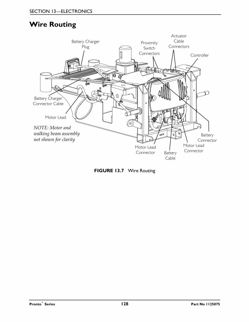
SECTION 13—ELECTRONICS
Wire Routing
FIGURE 13.7 Wire Routing
Motor Lead
Battery Charger Connector Cable
Proximity Switch
Connectors
Actuator Cable
ConnectorsBattery Charger
Plug
NOTE: Motor and walking beam assembly not shown for clarity
Battery Connector
Motor Lead Connector
Controller
Motor Lead ConnectorBattery
Cable
Pronto® Series 128 Part No 1125075

SECTION 14—ACCESSORIES
SECTION 14—ACCESSORIES
� WARNINGAfter any adjustments, repair or service and before use, make sure that all attaching hardware is tightened securely - otherwise injury or damage may result.
Before performing any maintenance, adjustment or service verify that On/Off switch on the joystick is in the Off position.
Installing/Removing the Crutch/Cane Holder
� WARNINGThe installation of the crutch/cane holder onto the back of the seat significantly increases the length of the wheelchair. When turning the wheelchair or swiveling the wheelchair seat, it is important to take note of this increased length - otherwise, injury and/or damage to the surrounding property may result.
NOTE: For this procedure, refer to FIGURE 14.1.
NOTE: The Crutch/Cane Holder and Oxygen Holder all install into the accessory tube. Only one of these may be installed at a time.
NOTE: To remove, reverse the following procedure.
Installing
1. If necessary, loosen but DO NOT remove the mounting knob.
2. Install the crutch/cane holder into the accessory tube located on the back of the seat.
3. Thread the mounting knob into the welded nut on the accessory tube. Securely tighten.
4. Align slot on base with hook on crutch/cane holder and slide base down into position.
FIGURE 14.1 Installing/Removing the Crutch/Cane Holder
Mounting Knob
Accessory Tube
Hook
Crutch/Cane Holder
Seat
Base
Part No 1125075 129 Pronto® Series

SECTION 14—ACCESSORIES
Installing/Removing the Oxygen Holder
� WARNINGContact your oxygen supplier for instructions in the use of oxygen. Extreme care MUST be exercised when using oxygen in close proximity to electric circuits.The Invacare oxygen holder is designed to be used in conjunction with oxygen cylinder models MD15 and ME24 only.To maintain safety, use only Invacare oxygen cylinder accessories (i.e. regulator, oxygen demand devices).DO NOT use the oxygen holder for anything other than its intended purpose of supporting an oxygen cylinder - otherwise, injury or damage may occur.DO NOT attempt to modify the oxygen holder to fit any other type of wheelchair. The oxygen holder was designed specifically for Invacare wheelchairs only.The installation of the oxygen holder onto the back of the wheelchair seat significantly increases the length of the wheelchair. When turning the wheelchair it is important to take note of this increased length - otherwise, injury or damage may occur.When using nasal or masked type administering equipment, oxygen or air tubing MUST be routed and secured properly to ensure that the tubing does not become entangled, kinked or severed. If necessary, loosen but DO NOT remove the mounting knob.
NOTE: For this procedure, refer to FIGURE 14.2.
NOTE: Reverse the following procedure to remove the oxygen holder.
NOTE: The O2 holder assembly can be mounted on the RIGHT or LEFT side of the seat back. Determine the appropriate side prior to installation.
1. Remove the top and bottom mounting screws and washers securing the upper hinge to the seat. Retain screws to install the O2 holder.
2. Align the O2 holder mounting holes with the mounting holes in the upper hinge and seat back as shown in FIGURE 14.2.
3. Using the two mounting screws and washers removed in STEP 1, secure the O2 holder to the upper hinge and seat back. Securely tighten.
FIGURE 14.2 Installing/Removing the Oxygen Holder
Top Mounting
Screw
Flat Washer
Flat Washer
O2 Holder
Right Side
Seat Back
O2 Cylinder
Upper Hinge
Bottom Mounting Screw
Left Side
Pronto® Series 130 Part No 1125075

SECTION 14—ACCESSORIES
Installing/Removing/Using the Walker Holder
� INSTALLATION WARNINGSAfter any adjustments, repair or service and before use, make sure that all attaching hardware is tightened securely.The installation of the walker holder onto the back of the wheelchair seat increases the length of the wheelchair up to nine inches. When turning the wheelchair it is important to take note of this increased length - otherwise, injury and/or damage to surrounding property may result.
NOTE: For this procedure, refer to FIGURE 14.3.
Installing/Removing the Walker HolderNOTE: Reverse this procedure to remove the walker holder.
1. If necessary, loosen but do not remove the mounting knob.
2. Install the walker holder into the accessory tube.
3. Thread the mounting knob into the welded nut on the accessory tube. Securely tighten.
Using the Walker Holder
1. Fold walker. Refer to instructions provided with the walker.
NOTE: Walker MUST be folded before using walker holder.
2. Hang folded walker on walker holder hooks.
3. Secure walker with hook and loop straps.
FIGURE 14.3 Installing/Removing/Using the Walker Holder
Seat
Accessory Tube
Mounting Knob
Walker Holder
Hook and Loop Straps
Hook
DETAIL “A”
Part No 1125075 131 Pronto® Series

Invacare Corporation www.invacare.com
USAOne Invacare WayElyria, Ohio USA44036-2125800-333-6900
Canada570 Matheson Blvd E Unit 8Mississauga OntarioL4Z 4G4 Canada800-668-5324
© 2015 Invacare Corporation. All rights reserved. Republication, duplication or modification in whole or in part is prohibited without prior written permission from Invacare. Trademarks are identified by ™ and ®. All trademarks are owned by or licensed to Invacare Corporation or its subsidiaries unless otherwise noted.
Part No. 1125075 Rev C~02 - 10/15
Making Life’s Experiences Possible™