Embed Size (px)
Citation preview
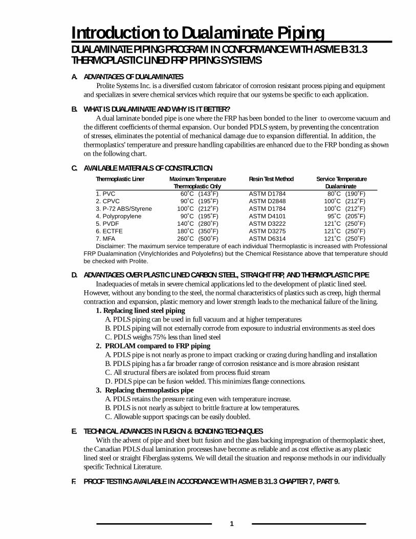
PROLITE SYSTEMS INC.PLASTICS DIVISION
C U S T O M FA B R I C AT O R S & D I S T R I B U T O R S O F C O R R O S I O N R E S I S TA N T P R O D U C T S
PSI20127 - 113B AvenueMaple Ridge, BCCanada V2X 0Z1
Tel: 604.460.8250Fax: 604.460.8254
www.prolitepiping.com
Contents
Introduction to Dualaminate Piping
PDLS-PVC/PDLS CPVC (PVC/FRP, CPVC/FRP)
PDLS-PP/ PDLS-PE (PP/FRP, PE/FRP)
PDLS-PV (PVDF/FRP)
PDLS-Halar (ECTFE/FRP)
PDLS (MFA/FRP)
Typical Properties of Most Engineered Thermoplastics
Design Parameters of PDLS Piping
Standard Dimensions of PDLS Piping
Metric DIN Standards
Japanese Industrial StandardsReferences to International Standards
1
2• Diagram – Thermoplastic Products:
Service Temperature versus Chemical Resistance 5
6
9
12• Diagram – Fluoropolymer Chemical Resistance:
Fluoropolymers within their Temperature Rating 15
16
19
20
• Filament Wound Pressure Pipe (Chlorolam-Class P, Chlorolam-Class C) 21• Filament Wound Pressure Pipe (Polylam-Class PP, Polylam-Class PE, 22
Fluorolam-Class PV, Flurolam-Class E, Fluorolam-Class M)• HLU Pressure Pipe (Chlorolam-Class P, Chlorolam-Class C) 23• HLU Pressure Pipe (Polylam-Class PP, Polylam-Class PE, 24
Fluorolam-Class PV, Flurolam-Class E, Fluorolam-Class M)• PDLS PVC/FRP and CPVC/FRP Full Face Flanges 25• PDLS PP/PE, PVDF, ECTFE and MFA Full Face Flanges 26• PDLS PP/PE, PVDF, ECTFE and MFA Stub Flanges 27
• Reference values for distance between supports [m] for pipes 28without thermal insulation
• Pipes to DIN 16 965, Part 2 29• Elbows to DIN 16 966, Part 2 30• T-Pieces and Branches to DIN 16 966, Part 4 31• Reducing Adapters, Concentric to DIN 16 966, Part 5 32• Reducing Adapters, Eccentric to DIN 16 966, Part 5 33• Nozzle with Bonded Collar and Backing Flange to DIN 16 966, Part 6 34• Connector with Integral Collar and Floating Flange to DIN 16 966, Part 6 35• Connector with Integral Fixed Flange to DIN 16 966, Part 6 36• Laminated Joints to DIN 16 966, Part 8 37
38
38
1
Introduction to Dualaminate PipingDUALAMINATE PIPING PROGRAM IN CONFORMANCE WITH ASME B 31.3THERMOPLASTIC LINED FRP PIPING SYSTEMSA. ADVANTAGES OF DUALAMINATES
Prolite Systems Inc. is a diversified custom fabricator of corrosion resistant process piping and equipmentand specializes in severe chemical services which require that our systems be specific to each application.
B. WHAT IS DUALAMINATE AND WHY IS IT BETTER?A dual laminate bonded pipe is one where the FRP has been bonded to the liner to overcome vacuum and
the different coefficients of thermal expansion. Our bonded PDLS system, by preventing the concentrationof stresses, eliminates the potential of mechanical damage due to expansion differential. In addition, thethermoplastics’ temperature and pressure handling capabilities are enhanced due to the FRP bonding as shownon the following chart.
C. AVAILABLE MATERIALS OF CONSTRUCTIONThermoplastic Liner Maximum Temperature Resin Test Method Service Temperature
Thermoplastic Only Dualaminate1. PVC 60˚C (143˚F) ASTM D1784 80˚C (190˚F)2. CPVC 90˚C (195˚F) ASTM D2848 100˚C (212˚F)3. P-72 ABS/Styrene 100˚C (212˚F) ASTM D1784 100˚C (212˚F)4. Polypropylene 90˚C (195˚F) ASTM D4101 95˚C (205˚F)5. PVDF 140˚C (280˚F) ASTM D3222 121˚C (250˚F)6. ECTFE 180˚C (350˚F) ASTM D3275 121˚C (250˚F)7. MFA 260˚C (500˚F) ASTM D6314 121˚C (250˚F)Disclaimer: The maximum service temperature of each individual Thermoplastic is increased with Professional
FRP Dualamination (Vinylchlorides and Polyolefins) but the Chemical Resistance above that temperature shouldbe checked with Prolite.
D. ADVANTAGES OVER PLASTIC LINED CARBON STEEL, STRAIGHT FRP, AND THERMOPLASTIC PIPEInadequacies of metals in severe chemical applications led to the development of plastic lined steel.
However, without any bonding to the steel, the normal characteristics of plastics such as creep, high thermalcontraction and expansion, plastic memory and lower strength leads to the mechanical failure of the lining.
1. Replacing lined steel pipingA. PDLS piping can be used in full vacuum and at higher temperaturesB. PDLS piping will not externally corrode from exposure to industrial environments as steel doesC. PDLS weighs 75% less than lined steel
2. PROLAM compared to FRP pipingA. PDLS pipe is not nearly as prone to impact cracking or crazing during handling and installationB. PDLS piping has a far broader range of corrosion resistance and is more abrasion resistantC. All structural fibers are isolated from process fluid streamD. PDLS pipe can be fusion welded. This minimizes flange connections.
3. Replacing thermoplastics pipeA. PDLS retains the pressure rating even with temperature increase.B. PDLS is not nearly as subject to brittle fracture at low temperatures.C. Allowable support spacings can be easily doubled.
E. TECHNICAL ADVANCES IN FUSION & BONDING TECHNIQUESWith the advent of pipe and sheet butt fusion and the glass backing impregnation of thermoplastic sheet,
the Canadian PDLS dual lamination processes have become as reliable and as cost effective as any plasticlined steel or straight Fiberglass systems. We will detail the situation and response methods in our individuallyspecific Technical Literature.
F. PROOF TESTING AVAILABLE IN ACCORDANCE WITH ASME B 31.3 CHAPTER 7, PART 9.
2
PDLS PVC/FRP AND CPVC/FRP Product and Material SpecificationsPRODUCT SPECIFICATIONS #APP 1961CHLOROLAM-CLASS P PIPING (PVC/FRP) AND CHLOROLAM-CLASS C (CPVC/FRP)
A. ADVANTAGES OF CHLOROLAM-CLASS P & CHLOROLAM-CLASS CPVC and CPVC are used as the basic chemical resistant liner for a very wide range of acids and alkalies at a
relatively low cost. They are resistant to most inorganic compounds and to a great many oxidants up to 80°C(PVC:FRP) and 100°C (CPVC:FRP). They are also resistant to most organic compounds except chlorinatedsolvents and aromatics.
B. APPLICATIONS OF CHLOROLAM-CLASS P & CHLOROLAM-CLASS CAt a moderate extra cost, PVC:FRP and CPVC:FRP dual laminates offer better chemical resistance and
longer service than Fiberglass. Like all thermoplastics, their abrasion resistance is better. With the advantage ofusing a wide range of PVC & CPVC resins, the bulk chemical businesses such as Sodium Chlorate, Chlorineand Caustic manufacturing have found very good success with these materials.
Other areas where these systems have been extensively used are in Zinc & Copper leaching processes usingSulphuric acid. Also Chlorine Dioxide manufacturing processes in Pulp & Paper bleaching are a major user.
SpecificationsPVC and CPVC LaminatesCHLOROLAM-CLASS P and CHLOROLAM-CLASS C
Special Fabrications – Chlorolam-Class NL and Chlorolam-Class HT:Prolite specializes in Trovidur Red NL unplasticized fabrications and Trovidur HT PVC-C fabrications.
Contact Prolite Engineering for custom systems.
1. SCOPEThe following design information applies to CHLOROLAM-CLASS P and CHLOROLAM-CLASS C
dual laminate or armoured thermoplastic piping products. This covers all piping, spooling, fittings and specialfabrications.
Pressure RatingsDual Laminate PDLS piping is available with pressure ratings of 50, 100 and150 psi.
Temperature RatingsFor continuous service operations, the maximum service temperatures should not exceedCHLOROLAM-CLASS P: — <180°FCORLAM-CLASS C: — <210°F
Thermal ExpansionCare should be exercised to compensate for thermal expansion & contraction forces, but for unreinforced
thermoplastics, the co-efficient is higher.CHLOROLAM-CLASS P 1.7 X 10⁻⁵/inch/inch/°FCORLAM-CLASS C
Bonding Procedure for CHLOROLAM-CLASS P and CHLOROLAM-CLASS CThe success of the PROLAM Systems Inc. lies with the chemical bond for PVC and CPVC bond
between the specific thermoplastic and the heterogenous fiberglass structural reinforcement. This bond isachieved by very careful preparation of the thermoplastic by sanding prior to applying the primary bondingagent. This is let cure for 24 hours. Subsequent to that, the fiberglass overlay is machine wound or customcontact moulded to achieve 7N/mm2 in accordance with DIN Test Method 53769 Part 1 for Shear strengthand ASTM D-1781-98 for Peel strength.
The general quality requirement is detailed in DIN 16964.
Vacuum ServiceThe bond strength and the fiberglass overlay allows PDLS piping to be made to accept full vacuum.
}
3
PDLS PVC/FRP AND CPVC/FRP Product and Material Specifications
2. MATERIALSOnly virgin pipe or sheet is used for thermoplastic liner. The thermoplastic resin will meet ASTM D-1784
requirements. A partial list of physical properties is shown below:Property PVC CPVC Test MethodSpecific Gravity 1.38-1.40 1.52 ASTM D-792Tensile Strength, psi 7,700 8,200 ASTM D-638
The fiberglass structural shall be made of either premium grade vinyl ester or polyester resin with the glassreinforcing applied by filament winding or by hand layup. The outer coating shall consist of a veil with a resinrich UV stabilized resin glaze coat. Where required, fire retardant resins can be used.
3. DIMENSIONAL DATAAll socket fittings shall conform to ASTM D-2567, all flanged fittings are to be in accordance with
ANSI B 16.0 for dimension and ANSI B 16.5 for standard 150 lb drilling. Socket fittings shall comply withASTM D-2467 for face to centerline dimensions.
TolerancesPipe and fitting tolerances are as follows:
Description Dimension TolerancesPipe spools Length ± 1/8”
Flange alignment ± 1/16”Flanges All data to comply ANSI B 16.5
except thicknessFittings Face to centerline ± 1/8”
Alignment ± 3/64”Flange I.D. radius 1/4” ± 1/16”
4. CORROSION RESISTANCEThermoplastic liner
The acid and alkali resistance of CHLOROLAM-CLASS P or CHLOROLAM-CLASS C is excellent. Forspecific data, consult Prolite.
Structural reinforcementThe chemical resistance of the vinylester or polyester resins to corrosive atmospheres does not normally
require any additional protection. This structural FRP casing also allows for direct burial. For specific environ-ments, consult Prolite.
Additional ServicesPDLS piping can be heat traced. Consult with Prolite. Without heat tracing and additional insulation,
the insulating properties are approximately K=1.5 BTU/ft/hr/°F/in.
5. FABRICATIONThermoplastic liner
All connections, flanges and fittings shall be joined to the pipe using hand welding and welding rod of the same resinquality. Butt fusion is permitted, where feasible. Where standard moulded fittings are used, they shall be cemented tothe pipe using proper thermoplastic procedures. All fittings shall be backwelded min. 24 hours after cementing. Anyfabricated pipe shall be fused along the length, where feasible, using modern automatic fusion machinery.
FiberglassAll fiberglass fabrication shall be in general accordance with NBS PS-15-69 for the structural reinforce-
ment. FRP reinforcements shall be made either by hand or via filament winding and comply with the requiredpipe pressure requirements. All thermoplastic fittings having an end lip, such as moulded connections, shallhave a putty radius applied to allow a smooth FRP overlay.
PermeationPermeation is not a problem with PDLS as it is with metal clad plastics. No weep holes are needed as
the FRP resin will allow and condensation to migrate safely.
4
PDLS PVC/FRP AND CPVC/FRP Product and Material Specifications
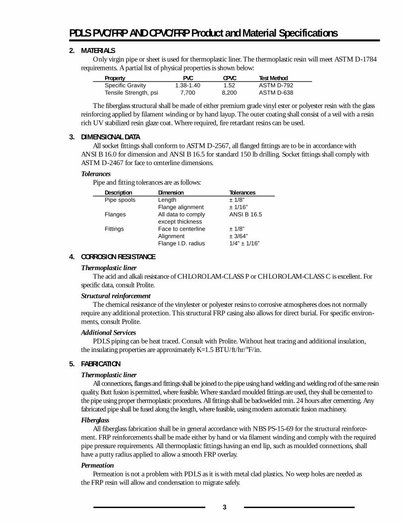
6. MAXIMUM BOLT TORQUE - FIBERGLASS FLANGES*Foot Pounds of TorqueNominal Internal Pipe Pressure Rating, PSIG, StandardDiameter 25 50 75 100 125 150
1” 15 15 15 15 15 151 1/2” 15 15 15 15 15 15
2” 25 25 25 25 25 253” 25 25 25 25 25 254” 25 25 25 30 30 306” 30 30 30 30 30 408” 30 30 35 40 40 40
10” 30 30 35 40 40 4012” 30 30 40 40 40 4514” 35 35 40 50 50 5016” 35 35 40 50 50 5018” 35 35 40 50 50 5020” 35 35 40 50 60 6024” 45 45 45 60 65 65
* The indicated bolt torque is required to seat gaskets of 65 durometer on full face flanges.
Torque of BoltsA. Grease all bolts and nuts with a suitable grease, finger tighten all nuts.B. With torque wrench, using a crisscross method, tighten each bolt until the torque for each bolt falls
within the range listed above.C. After 24-30 hours or a temperature cycle or a pressure cycle, torque for each bolt shall be checked and
those below the minimum are to be re-torqued to the range listed above.
Auxiliary neoprene gaskets and spacers must be used when flanging CHLOROLAM-CLASS P/CHLOROLAM- CLASS C of dissimilar material. Recommended gaskets to be 55 – 70 durometer.
Small SAE washers shall be used on all flanged fittings.
7. APPROXIMATE WEIGHTS OF CHLOROLAM-CLASS P/CHLOROLAM-CLASS C PIPES AND FITTINGS (in lbs.):Pipe Size 1-1/2” 2” 3” 4” 6” 8” 10” 12”Weight/Ft. 1.75 2.05 3.75 4.34 7.05 11.16 16.25 22.07Flanged 90° ELL 3.5 4.5 8.1 12.5 23.7 40.7 60.6 98.8Flanged 45° ELL 2.7 3.7 6.6 10.4 18.3 29.8 42.8 69.2Flanged Tee 4.5 6.0 11.2 16.9 32.5 53.5 80.0 126.7Flanged Cross 6.0 8.0 15.0 22.6 43.4 71.4 106.7 169.0Flanged 45° Lateral 4.9 6.6 12.1 19.0 37.2 64.1 95.3 158.2Flange 1.0 1.3 2.4 3.8 6.3 10.2 13.7 21.8Based on Filament Wound pipe. Flanges and fittings are contact moulded.
8. EXPANSION AND CONTRACTION OF PLASTIC PIPE (THERMOPLASTIC ONLY)Calculating Dimensional ChangePlastics, like other piping materials, undergo dimensional changes as a result of temperature variations
above and below the installation temperature. The extent of expansion or contraction is dependent upon thepiping material of construction and its coefficient of linear expansion which, for convenience, is listed below forseveral materials in units of inches of expansion per 10°F temperature change per 100 feet of pipe. It is alsolisted in the more conventional form of inches of expansion per inch of length.
Expansion CoefficientMaterial -in/in/°F x 10-5 Y-in/10°F/100 ft.PVC 4.0 .360CPVC 3.8 .456PP 8.0 .600PVDF 7.0 .948
5
PDLS PVC/FRP AND CPVC/FRP Product and Material Specifications
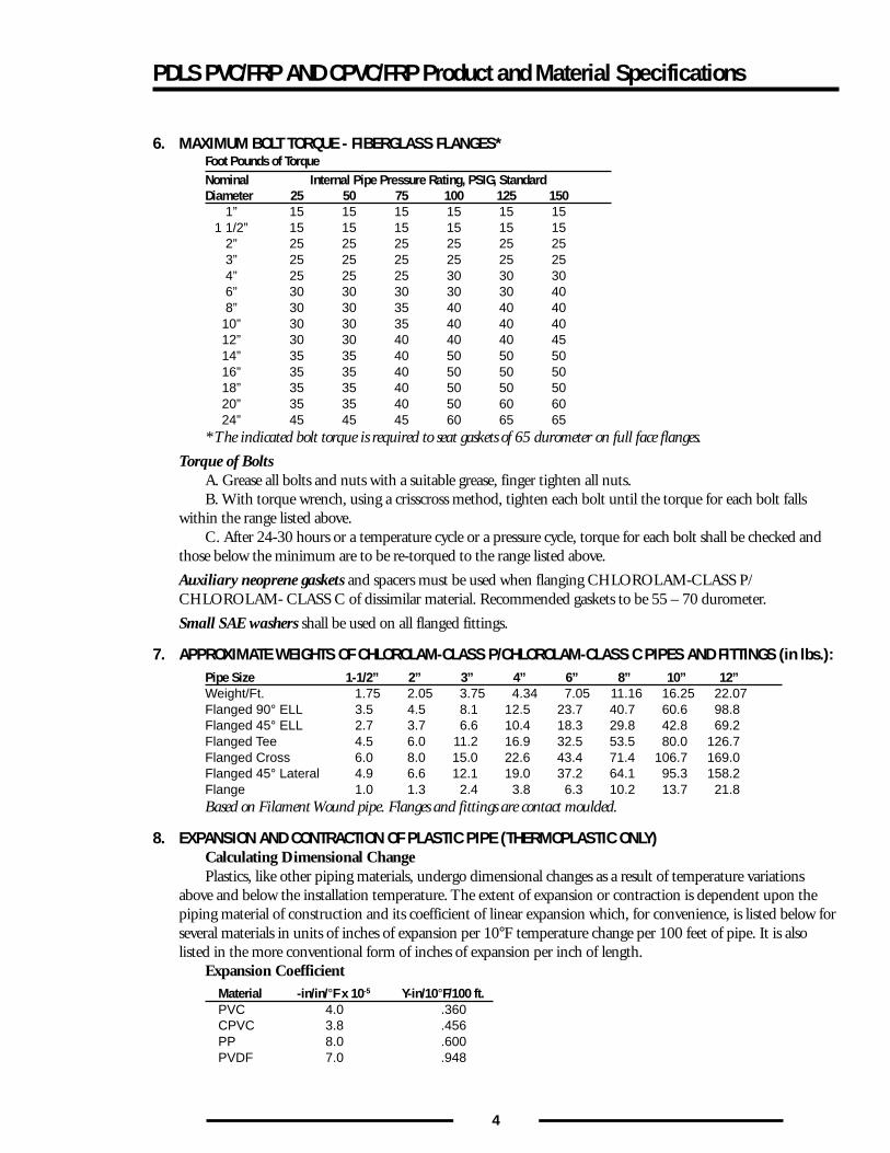
The degree of thermal expansion or contraction is also dependent upon the system temperature differentialas well as the length of pipe run between changes in direction and it can be calculated using the followingformula:
∆L = Y(T1 - T2) X _L_ 10 100
∆L = Dimensional change due to thermal expansion or contraction (in.).
Y = Expansion Coefficient (See Table above).(in/10°F/100 ft)
(T1 - T2) = Temperature Differential between the installation temperature and the maximum orminimum system temperature, which provides the greatest differential (°F).
L = Length of pipe run between changes in direction (ft).
9. For all fittings and dimensional drawings, such as 90˚ Elbows, 45˚ Elbows and Concentric Reducers,Contact Prolite Engineering.
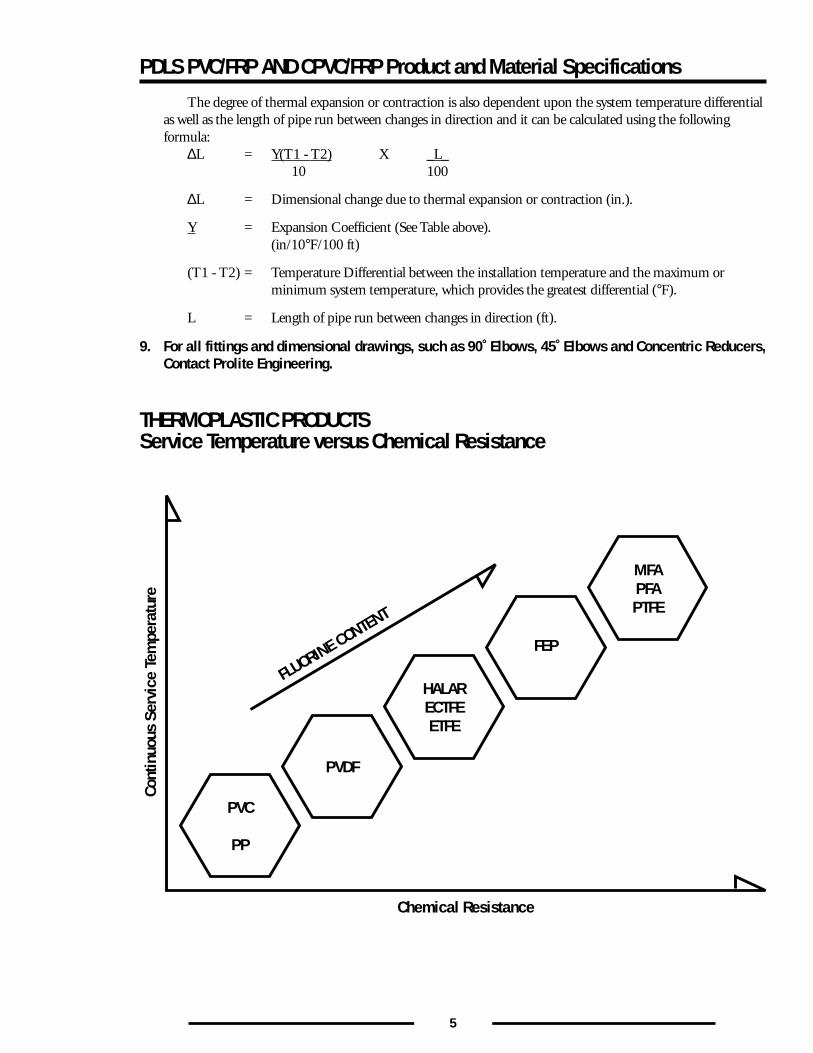
THERMOPLASTIC PRODUCTSService Temperature versus Chemical Resistance
Chemical Resistance
PVC
PP
FLUORINE CONTENT
Cont
inuo
us S
ervi
ce T
empe
ratu
re
PVDF
HALARECTFEETFE
FEP
MFAPFAPTFE
6
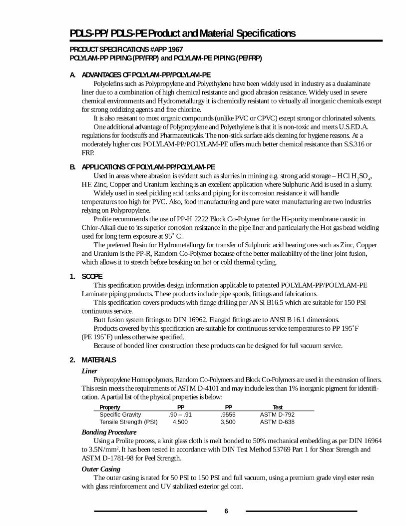
PDLS-PP/ PDLS-PE Product and Material SpecificationsPRODUCT SPECIFICATIONS #APP 1967POLYLAM-PP PIPING (PP/FRP) and POLYLAM-PE PIPING (PE/FRP)
A. ADVANTAGES OF POLYLAM-PP/POLYLAM-PEPolyolefins such as Polypropylene and Polyethylene have been widely used in industry as a dualaminate
liner due to a combination of high chemical resistance and good abrasion resistance. Widely used in severechemical environments and Hydrometallurgy it is chemically resistant to virtually all inorganic chemicals exceptfor strong oxidizing agents and free chlorine.
It is also resistant to most organic compounds (unlike PVC or CPVC) except strong or chlorinated solvents.One additional advantage of Polypropylene and Polyethylene is that it is non-toxic and meets U.S.F.D.A.
regulations for foodstuffs and Pharmaceuticals. The non-stick surface aids cleaning for hygiene reasons. At amoderately higher cost POLYLAM-PP/POLYLAM-PE offers much better chemical resistance than S.S.316 orFRP.
B. APPLICATIONS OF POLYLAM-PP/POLYLAM-PEUsed in areas where abrasion is evident such as slurries in mining e.g. strong acid storage – HCl H
2SO
4,
HF. Zinc, Copper and Uranium leaching is an excellent application where Sulphuric Acid is used in a slurry.Widely used in steel pickling acid tanks and piping for its corrosion resistance it will handle
temperatures too high for PVC. Also, food manufacturing and pure water manufacturing are two industriesrelying on Polypropylene.
Prolite recommends the use of PP-H 2222 Block Co-Polymer for the Hi-purity membrane caustic inChlor-Alkali due to its superior corrosion resistance in the pipe liner and particularly the Hot gas bead weldingused for long term exposure at 95˚ C.
The preferred Resin for Hydrometallurgy for transfer of Sulphuric acid bearing ores such as Zinc, Copperand Uranium is the PP-R, Random Co-Polymer because of the better malleability of the liner joint fusion,which allows it to stretch before breaking on hot or cold thermal cycling.
1. SCOPEThis specification provides design information applicable to patented POLYLAM-PP/POLYLAM-PE
Laminate piping products. These products include pipe spools, fittings and fabrications.This specification covers products with flange drilling per ANSI B16.5 which are suitable for 150 PSI
continuous service.Butt fusion system fittings to DIN 16962. Flanged fittings are to ANSI B 16.1 dimensions.Products covered by this specification are suitable for continuous service temperatures to PP 195˚F
(PE 195˚F) unless otherwise specified.Because of bonded liner construction these products can be designed for full vacuum service.
2. MATERIALSLiner
Polypropylene Homopolymers, Random Co-Polymers and Block Co-Polymers are used in the extrusion of liners.This resin meets the requirements of ASTM D-4101 and may include less than 1% inorganic pigment for identifi-cation. A partial list of the physical properties is below:
Property PP PP TestSpecific Gravity .90 – .91 .9555 ASTM D-792Tensile Strength (PSI) 4,500 3,500 ASTM D-638
Bonding ProcedureUsing a Prolite process, a knit glass cloth is melt bonded to 50% mechanical embedding as per DIN 16964
to 3.5N/mm2. It has been tested in accordance with DIN Test Method 53769 Part 1 for Shear Strength andASTM D-1781-98 for Peel Strength.
Outer CasingThe outer casing is rated for 50 PSI to 150 PSI and full vacuum, using a premium grade vinyl ester resin
with glass reinforcement and UV stabilized exterior gel coat.
7
PDLS PP/FRP AND PE/FRP Product and Material Specifications
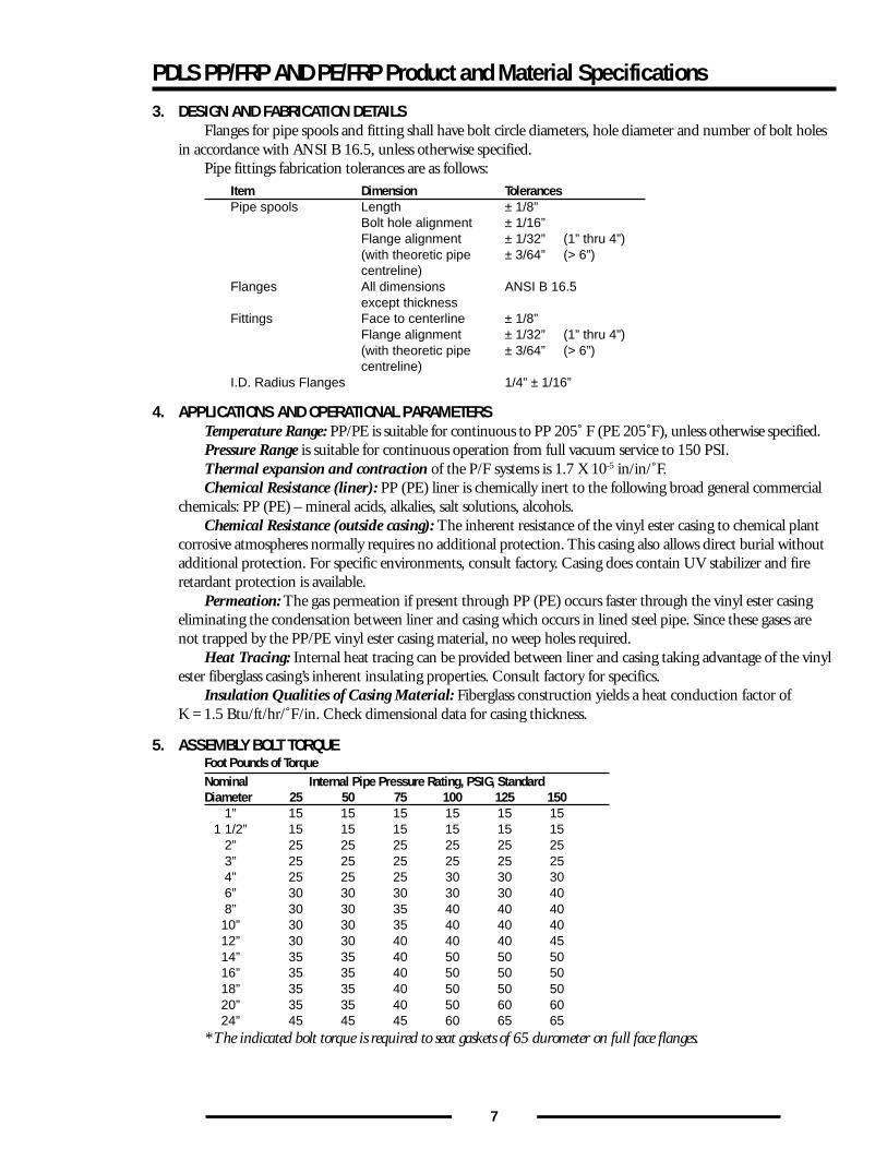
3. DESIGN AND FABRICATION DETAILSFlanges for pipe spools and fitting shall have bolt circle diameters, hole diameter and number of bolt holes
in accordance with ANSI B 16.5, unless otherwise specified.Pipe fittings fabrication tolerances are as follows:
Item Dimension TolerancesPipe spools Length ± 1/8”
Bolt hole alignment ± 1/16”Flange alignment ± 1/32” (1” thru 4”)(with theoretic pipe ± 3/64” (> 6”)centreline)
Flanges All dimensions ANSI B 16.5except thickness
Fittings Face to centerline ± 1/8”Flange alignment ± 1/32” (1” thru 4”)(with theoretic pipe ± 3/64” (> 6”)centreline)
I.D. Radius Flanges 1/4” ± 1/16”
4. APPLICATIONS AND OPERATIONAL PARAMETERSTemperature Range: PP/PE is suitable for continuous to PP 205˚ F (PE 205˚F), unless otherwise specified.Pressure Range is suitable for continuous operation from full vacuum service to 150 PSI.Thermal expansion and contraction of the P/F systems is 1.7 X 10⁻⁵ in/in/˚F.Chemical Resistance (liner): PP (PE) liner is chemically inert to the following broad general commercial
chemicals: PP (PE) – mineral acids, alkalies, salt solutions, alcohols.Chemical Resistance (outside casing): The inherent resistance of the vinyl ester casing to chemical plant
corrosive atmospheres normally requires no additional protection. This casing also allows direct burial withoutadditional protection. For specific environments, consult factory. Casing does contain UV stabilizer and fireretardant protection is available.
Permeation: The gas permeation if present through PP (PE) occurs faster through the vinyl ester casingeliminating the condensation between liner and casing which occurs in lined steel pipe. Since these gases arenot trapped by the PP/PE vinyl ester casing material, no weep holes required.
Heat Tracing: Internal heat tracing can be provided between liner and casing taking advantage of the vinylester fiberglass casing’s inherent insulating properties. Consult factory for specifics.
Insulation Qualities of Casing Material: Fiberglass construction yields a heat conduction factor ofK = 1.5 Btu/ft/hr/˚F/in. Check dimensional data for casing thickness.
5. ASSEMBLY BOLT TORQUEFoot Pounds of TorqueNominal Internal Pipe Pressure Rating, PSIG, StandardDiameter 25 50 75 100 125 150
1” 15 15 15 15 15 151 1/2” 15 15 15 15 15 15
2” 25 25 25 25 25 253” 25 25 25 25 25 254” 25 25 25 30 30 306” 30 30 30 30 30 408” 30 30 35 40 40 4010” 30 30 35 40 40 4012” 30 30 40 40 40 4514” 35 35 40 50 50 5016” 35 35 40 50 50 5018” 35 35 40 50 50 5020” 35 35 40 50 60 6024” 45 45 45 60 65 65
* The indicated bolt torque is required to seat gaskets of 65 durometer on full face flanges.
8
PDLS PP/FRP AND PE/FRP Product and Material Specifications
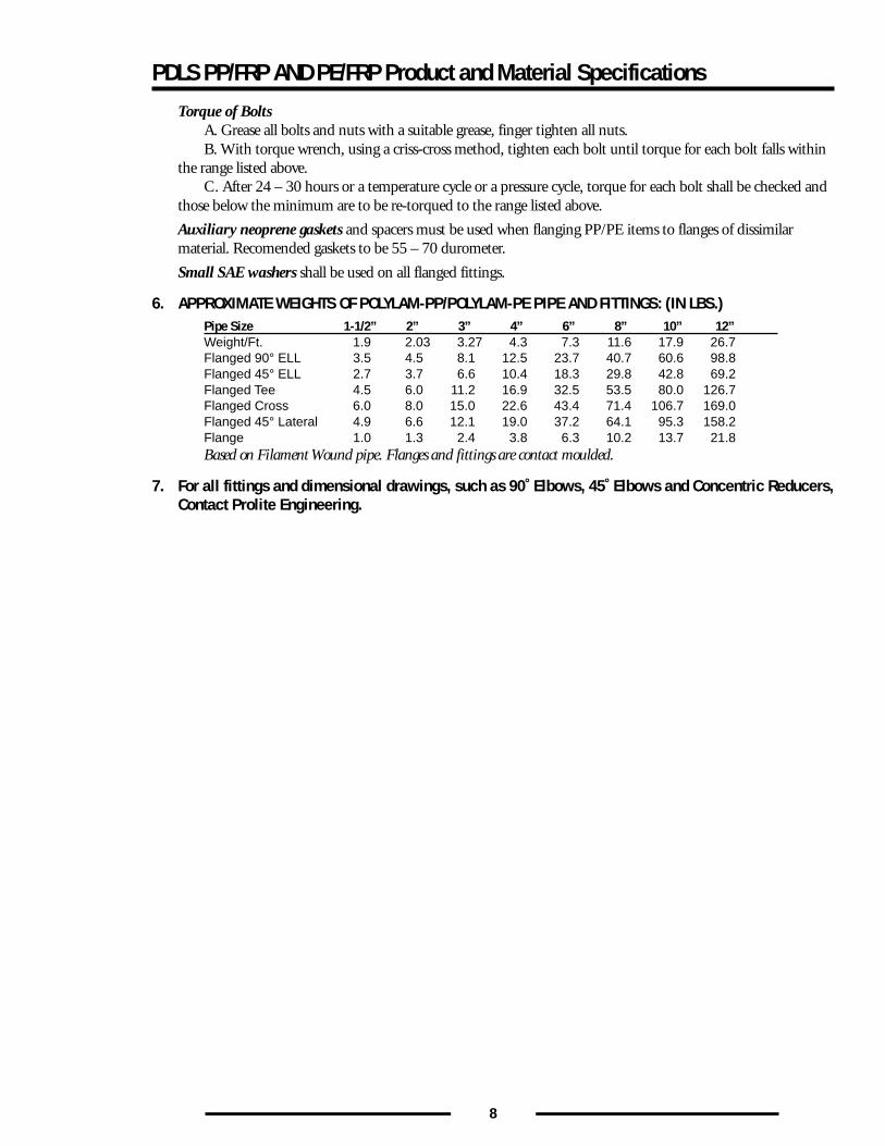
Torque of BoltsA. Grease all bolts and nuts with a suitable grease, finger tighten all nuts.B. With torque wrench, using a criss-cross method, tighten each bolt until torque for each bolt falls within
the range listed above.C. After 24 – 30 hours or a temperature cycle or a pressure cycle, torque for each bolt shall be checked and
those below the minimum are to be re-torqued to the range listed above.
Auxiliary neoprene gaskets and spacers must be used when flanging PP/PE items to flanges of dissimilarmaterial. Recomended gaskets to be 55 – 70 durometer.
Small SAE washers shall be used on all flanged fittings.
6. APPROXIMATE WEIGHTS OF POLYLAM-PP/POLYLAM-PE PIPE AND FITTINGS: (IN LBS.)Pipe Size 1-1/2” 2” 3” 4” 6” 8” 10” 12”Weight/Ft. 1.9 2.03 3.27 4.3 7.3 11.6 17.9 26.7Flanged 90° ELL 3.5 4.5 8.1 12.5 23.7 40.7 60.6 98.8Flanged 45° ELL 2.7 3.7 6.6 10.4 18.3 29.8 42.8 69.2Flanged Tee 4.5 6.0 11.2 16.9 32.5 53.5 80.0 126.7Flanged Cross 6.0 8.0 15.0 22.6 43.4 71.4 106.7 169.0Flanged 45° Lateral 4.9 6.6 12.1 19.0 37.2 64.1 95.3 158.2Flange 1.0 1.3 2.4 3.8 6.3 10.2 13.7 21.8Based on Filament Wound pipe. Flanges and fittings are contact moulded.
7. For all fittings and dimensional drawings, such as 90˚ Elbows, 45˚ Elbows and Concentric Reducers,Contact Prolite Engineering.
9
PDLS-PV (PVDF/FRP) Product and Material SpecificationsPRODUCT SPECIFICATIONS #APP 1972PDLS-PV (PVDF/FRP) FLUOROLAM-CLASS PV PIPING
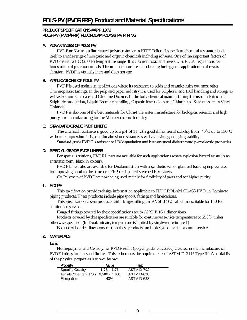
A. ADVANTAGES OF PDLS-PVPVDF or Kynar is a fluorinated polymer similar to PTFE Teflon. Its excellent chemical resistance lends
itself to a wide range of inorganic and organic chemicals including solvents. One of the important factors ofPVDF is its 121˚C (250˚F) temperature range. It is also non toxic and meets U.S. F.D.A. regulations forfoodstuffs and pharmaceuticals. The non-stick surface aids cleaning for hygienic applications and resistsabrasion. PVDF is virtually inert and does not age.
B. APPLICATIONS OF PDLS-PVPVDF is used mainly in applications where its resistance to acids and organics rules out most other
Thermoplastic Linings. In the pulp and paper industry it is used for Sulphuric and HCl handling and storage aswell as Sodium Chlorate and Chlorine Dioxide. In the bulk chemical manufacturing it is used in Nitric andSulphuric production, Liquid Bromine handling, Organic Insecticides and Chlorinated Solvents such as VinylChloride.
PVDF is also one of the best materials for Ultra-Pure water manufacture for biological research and highpurity acid manufacturing for the Microelectronic Industry.
C. STANDARD GRADE PVDF LINERSThe chemical resistance is good up to a pH of 11 with good dimensional stability from -40˚C up to 150˚C
without compression. It is good for abrasion resistance as well as having good aging stability.Standard grade PVDF is resistant to UV degradation and has very good dielectric and piezoelectric properties.
D. SPECIAL GRADE PVDF LINERSFor special situations, PVDF Liners are available for such applications where explosion hazard exists, in an
antistatic form (black in colour).PVDF Liners also are available for Dualamination with a synthetic veil or glass veil backing impregnated
for improving bond to the structural FRP, or chemically etched HV Liners.Co-Polymers of PVDF are now being used mainly for flexibility of parts and for higher purity.
1. SCOPEThis specification provides design information applicable to FLUOROLAM CLASS-PV Dual Laminate
piping products. These products include pipe spools, fittings and fabrications.This specification covers products with flange drilling per ANSI B 16.5 which are suitable for 150 PSI
continuous service.Flanged fittings covered by these specifications are to ANSI B 16.1 dimensions.Products covered by this specification are suitable for continuous service temperatures to 250˚F unless
otherwise specified. (In Dualaminate, temperature is limited by vinylester resin used.)Because of bonded liner construction these products can be designed for full vacuum service.
2. MATERIALSLiner
Homopolymer and Co-Polymer PVDF resins (polyvinylidene fluoride) are used in the manufacture ofPVDF linings for pipe and fittings. This resin meets the requirements of ASTM D-2116 Type III. A partial listof the physical properties is shown below:
Property Value TestSpecific Gravity 1.76 – 1.78 ASTM D-792Tensile Strength (PSI) 6,500 - 7,100 ASTM D-638Elongation 40% ASTM D-638
10
PDLS-PV (PVDF/FRP) Product and Material Specifications
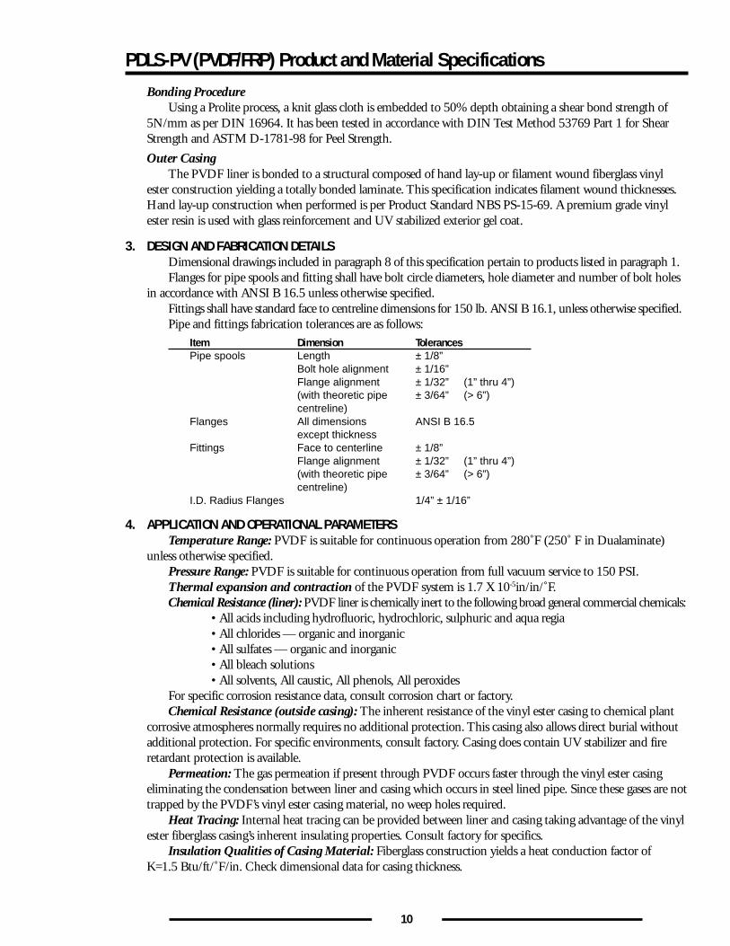
Bonding ProcedureUsing a Prolite process, a knit glass cloth is embedded to 50% depth obtaining a shear bond strength of
5N/mm as per DIN 16964. It has been tested in accordance with DIN Test Method 53769 Part 1 for ShearStrength and ASTM D-1781-98 for Peel Strength.
Outer CasingThe PVDF liner is bonded to a structural composed of hand lay-up or filament wound fiberglass vinyl
ester construction yielding a totally bonded laminate. This specification indicates filament wound thicknesses.Hand lay-up construction when performed is per Product Standard NBS PS-15-69. A premium grade vinylester resin is used with glass reinforcement and UV stabilized exterior gel coat.
3. DESIGN AND FABRICATION DETAILSDimensional drawings included in paragraph 8 of this specification pertain to products listed in paragraph 1.Flanges for pipe spools and fitting shall have bolt circle diameters, hole diameter and number of bolt holes
in accordance with ANSI B 16.5 unless otherwise specified.Fittings shall have standard face to centreline dimensions for 150 lb. ANSI B 16.1, unless otherwise specified.Pipe and fittings fabrication tolerances are as follows:
Item Dimension TolerancesPipe spools Length ± 1/8”
Bolt hole alignment ± 1/16”Flange alignment ± 1/32” (1” thru 4”)(with theoretic pipe ± 3/64” (> 6”)centreline)
Flanges All dimensions ANSI B 16.5except thickness
Fittings Face to centerline ± 1/8”Flange alignment ± 1/32” (1” thru 4”)(with theoretic pipe ± 3/64” (> 6”)centreline)
I.D. Radius Flanges 1/4” ± 1/16”
4. APPLICATION AND OPERATIONAL PARAMETERSTemperature Range: PVDF is suitable for continuous operation from 280˚F (250˚ F in Dualaminate)
unless otherwise specified.Pressure Range: PVDF is suitable for continuous operation from full vacuum service to 150 PSI.Thermal expansion and contraction of the PVDF system is 1.7 X 10⁻⁵in/in/˚F.Chemical Resistance (liner): PVDF liner is chemically inert to the following broad general commercial chemicals:
• All acids including hydrofluoric, hydrochloric, sulphuric and aqua regia• All chlorides — organic and inorganic• All sulfates — organic and inorganic• All bleach solutions• All solvents, All caustic, All phenols, All peroxides
For specific corrosion resistance data, consult corrosion chart or factory.Chemical Resistance (outside casing): The inherent resistance of the vinyl ester casing to chemical plant
corrosive atmospheres normally requires no additional protection. This casing also allows direct burial withoutadditional protection. For specific environments, consult factory. Casing does contain UV stabilizer and fireretardant protection is available.
Permeation: The gas permeation if present through PVDF occurs faster through the vinyl ester casingeliminating the condensation between liner and casing which occurs in steel lined pipe. Since these gases are nottrapped by the PVDF’s vinyl ester casing material, no weep holes required.
Heat Tracing: Internal heat tracing can be provided between liner and casing taking advantage of the vinylester fiberglass casing’s inherent insulating properties. Consult factory for specifics.
Insulation Qualities of Casing Material: Fiberglass construction yields a heat conduction factor ofK=1.5 Btu/ft/˚F/in. Check dimensional data for casing thickness.
11
PDLS-PV (PVDF/FRP) Product and Material Specifications
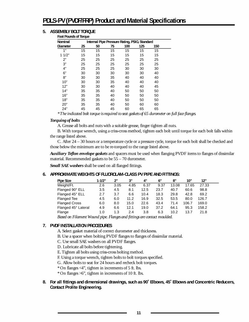
5. ASSEMBLY BOLT TORQUEFoot Pounds of TorqueNominal Internal Pipe Pressure Rating, PSIG, StandardDiameter 25 50 75 100 125 150
1” 15 15 15 15 15 151 1/2” 15 15 15 15 15 15
2” 25 25 25 25 25 253” 25 25 25 25 25 254” 25 25 25 30 30 306” 30 30 30 30 30 408” 30 30 35 40 40 4010” 30 30 35 40 40 4012” 30 30 40 40 40 4514” 35 35 40 50 50 5016” 35 35 40 50 50 5018” 35 35 40 50 50 5020” 35 35 40 50 60 6024” 45 45 45 60 65 65
* The indicated bolt torque is required to seat gaskets of 65 durometer on full face flanges.
Torquing of boltsA. Grease all bolts and nuts with a suitable grease, finger tighten all nuts.B. With torque wrench, using a criss-cross method, tighten each bolt until torque for each bolt falls within
the range listed above.C. After 24 – 30 hours or a temperature cycle or a pressure cycle, torque for each bolt shall be checked and
those below the minimum are to be re-torqued to the range listed above.
Auxiliary Teflon envelope gaskets and spacers must be used when flanging PVDF items to flanges of dissimilarmaterial. Recommended gaskets to be 55 – 70 durometer.
Small SAE washers shall be used on all flanged fittings.
6. APPROXIMATE WEIGHTS OF FLUOROLAM-CLASS PV PIPE AND FITTINGS:Pipe Size 1-1/2” 2” 3” 4” 6” 8” 10” 12”Weight/Ft. 2.6 3.05 4.85 6.37 9.37 13.08 17.65 27.33Flanged 90° ELL 3.5 4.5 8.1 12.5 23.7 40.7 60.6 98.8Flanged 45° ELL 2.7 3.7 6.6 10.4 18.3 29.8 42.8 69.2Flanged Tee 4.5 6.0 11.2 16.9 32.5 53.5 80.0 126.7Flanged Cross 6.0 8.0 15.0 22.6 43.4 71.4 106.7 169.0Flanged 45° Lateral 4.9 6.6 12.1 19.0 37.2 64.1 95.3 158.2Flange 1.0 1.3 2.4 3.8 6.3 10.2 13.7 21.8Based on Filament Wound pipe. Flanges and fittings are contact moulded.
7. PVDF INSTALLATION PROCEDURESA. Select gasket material of correct durometer and thickness.B. Use a spacer when bolting PVDF flanges to flanges of dissimilar material.C. Use small SAE washers on all PVDF flanges.D. Lubricate all bolts before tightening.E. Tighten all bolts using criss-cross bolting method.F. Using a torque wrench, tighten bolts to bolt torques specified.G. Allow bolts to seat for 24 hours and recheck bolt torques.* On flanges <4”, tighten in increments of 5 ft. lbs.* On flanges >6”, tighten in increments of 10 ft. lbs.
8. For all fittings and dimensional drawings, such as 90˚ Elbows, 45˚ Elbows and Concentric Reducers,Contact Prolite Engineering.
12
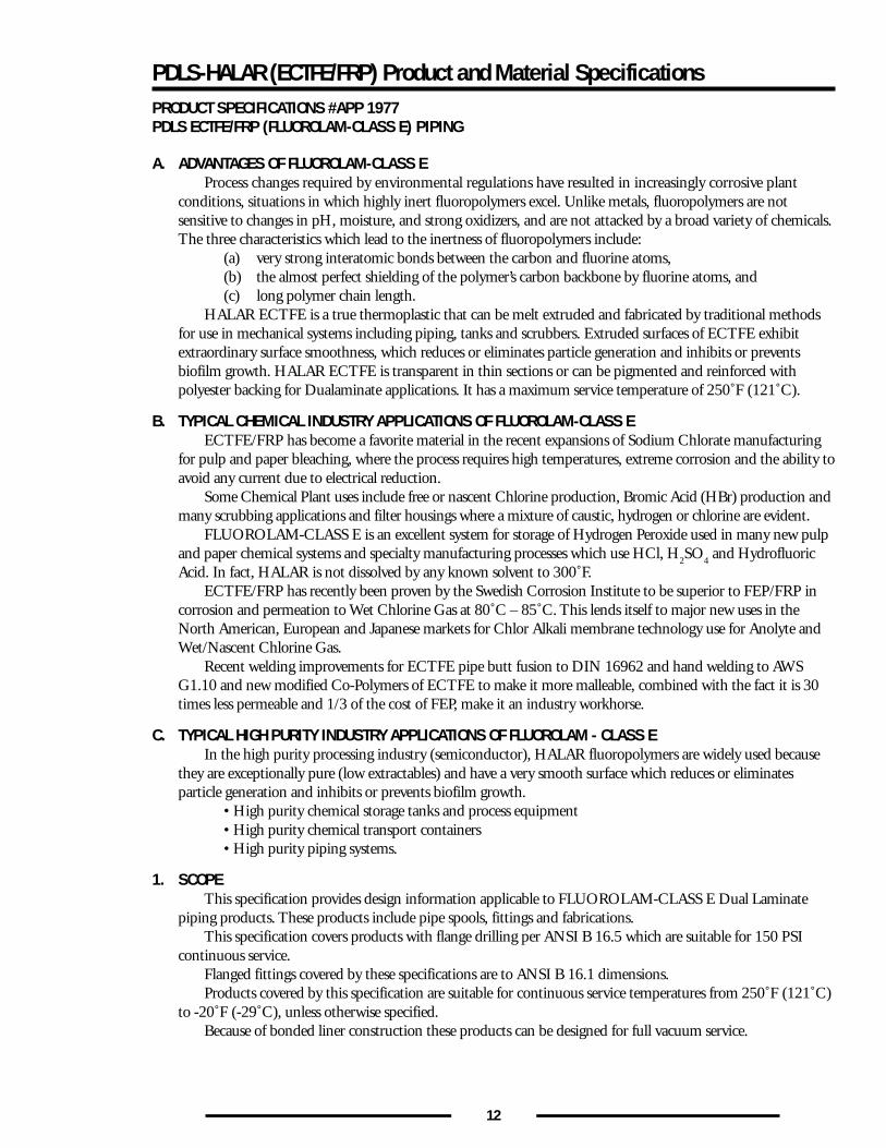
PDLS-HALAR (ECTFE/FRP) Product and Material SpecificationsPRODUCT SPECIFICATIONS #APP 1977PDLS ECTFE/FRP (FLUOROLAM-CLASS E) PIPING
A. ADVANTAGES OF FLUOROLAM-CLASS EProcess changes required by environmental regulations have resulted in increasingly corrosive plant
conditions, situations in which highly inert fluoropolymers excel. Unlike metals, fluoropolymers are notsensitive to changes in pH, moisture, and strong oxidizers, and are not attacked by a broad variety of chemicals.The three characteristics which lead to the inertness of fluoropolymers include:
(a) very strong interatomic bonds between the carbon and fluorine atoms,(b) the almost perfect shielding of the polymer’s carbon backbone by fluorine atoms, and(c) long polymer chain length.
HALAR ECTFE is a true thermoplastic that can be melt extruded and fabricated by traditional methodsfor use in mechanical systems including piping, tanks and scrubbers. Extruded surfaces of ECTFE exhibitextraordinary surface smoothness, which reduces or eliminates particle generation and inhibits or preventsbiofilm growth. HALAR ECTFE is transparent in thin sections or can be pigmented and reinforced withpolyester backing for Dualaminate applications. It has a maximum service temperature of 250˚F (121˚C).
B. TYPICAL CHEMICAL INDUSTRY APPLICATIONS OF FLUOROLAM-CLASS EECTFE/FRP has become a favorite material in the recent expansions of Sodium Chlorate manufacturing
for pulp and paper bleaching, where the process requires high temperatures, extreme corrosion and the ability toavoid any current due to electrical reduction.
Some Chemical Plant uses include free or nascent Chlorine production, Bromic Acid (HBr) production andmany scrubbing applications and filter housings where a mixture of caustic, hydrogen or chlorine are evident.
FLUOROLAM-CLASS E is an excellent system for storage of Hydrogen Peroxide used in many new pulpand paper chemical systems and specialty manufacturing processes which use HCl, H
2SO
4 and Hydrofluoric
Acid. In fact, HALAR is not dissolved by any known solvent to 300˚F.ECTFE/FRP has recently been proven by the Swedish Corrosion Institute to be superior to FEP/FRP in
corrosion and permeation to Wet Chlorine Gas at 80˚C – 85˚C. This lends itself to major new uses in theNorth American, European and Japanese markets for Chlor Alkali membrane technology use for Anolyte andWet/Nascent Chlorine Gas.
Recent welding improvements for ECTFE pipe butt fusion to DIN 16962 and hand welding to AWSG1.10 and new modified Co-Polymers of ECTFE to make it more malleable, combined with the fact it is 30times less permeable and 1/3 of the cost of FEP, make it an industry workhorse.
C. TYPICAL HIGH PURITY INDUSTRY APPLICATIONS OF FLUOROLAM - CLASS EIn the high purity processing industry (semiconductor), HALAR fluoropolymers are widely used because
they are exceptionally pure (low extractables) and have a very smooth surface which reduces or eliminatesparticle generation and inhibits or prevents biofilm growth.
• High purity chemical storage tanks and process equipment• High purity chemical transport containers• High purity piping systems.
1. SCOPEThis specification provides design information applicable to FLUOROLAM-CLASS E Dual Laminate
piping products. These products include pipe spools, fittings and fabrications.This specification covers products with flange drilling per ANSI B 16.5 which are suitable for 150 PSI
continuous service.Flanged fittings covered by these specifications are to ANSI B 16.1 dimensions.Products covered by this specification are suitable for continuous service temperatures from 250˚F (121˚C)
to -20˚F (-29˚C), unless otherwise specified.Because of bonded liner construction these products can be designed for full vacuum service.
13
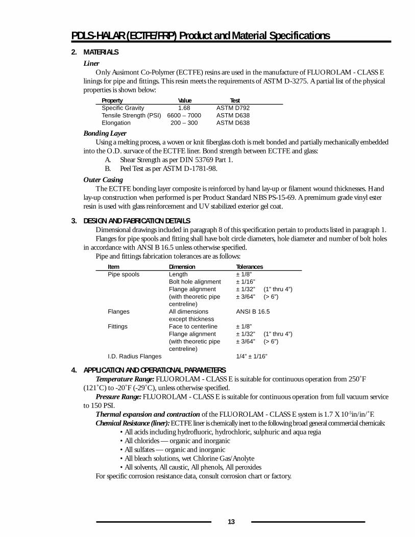
PDLS-HALAR (ECTFE/FRP) Product and Material Specifications2. MATERIALS
LinerOnly Ausimont Co-Polymer (ECTFE) resins are used in the manufacture of FLUOROLAM - CLASS E
linings for pipe and fittings. This resin meets the requirements of ASTM D-3275. A partial list of the physicalproperties is shown below:
Property Value TestSpecific Gravity 1.68 ASTM D792Tensile Strength (PSI) 6600 – 7000 ASTM D638Elongation 200 – 300 ASTM D638
Bonding LayerUsing a melting process, a woven or knit fiberglass cloth is melt bonded and partially mechanically embedded
into the O.D. survace of the ECTFE liner. Bond strength between ECTFE and glass:A. Shear Strength as per DIN 53769 Part 1.B. Peel Test as per ASTM D-1781-98.
Outer CasingThe ECTFE bonding layer composite is reinforced by hand lay-up or filament wound thicknesses. Hand
lay-up construction when performed is per Product Standard NBS PS-15-69. A premimum grade vinyl esterresin is used with glass reinforcement and UV stabilized exterior gel coat.
3. DESIGN AND FABRICATION DETAILSDimensional drawings included in paragraph 8 of this specification pertain to products listed in paragraph 1.Flanges for pipe spools and fitting shall have bolt circle diameters, hole diameter and number of bolt holes
in accordance with ANSI B 16.5 unless otherwise specified.Pipe and fittings fabrication tolerances are as follows:
Item Dimension TolerancesPipe spools Length ± 1/8”
Bolt hole alignment ± 1/16”Flange alignment ± 1/32” (1” thru 4”)(with theoretic pipe ± 3/64” (> 6”)centreline)
Flanges All dimensions ANSI B 16.5except thickness
Fittings Face to centerline ± 1/8”Flange alignment ± 1/32” (1” thru 4”)(with theoretic pipe ± 3/64” (> 6”)centreline)
I.D. Radius Flanges 1/4” ± 1/16”
4. APPLICATION AND OPERATIONAL PARAMETERSTemperature Range: FLUOROLAM - CLASS E is suitable for continuous operation from 250˚F
(121˚C) to -20˚F (-29˚C), unless otherwise specified.Pressure Range: FLUOROLAM - CLASS E is suitable for continuous operation from full vacuum service
to 150 PSI.Thermal expansion and contraction of the FLUOROLAM - CLASS E system is 1.7 X 10⁻⁵in/in/˚F.Chemical Resistance (liner): ECTFE liner is chemically inert to the following broad general commercial chemicals:
• All acids including hydrofluoric, hydrochloric, sulphuric and aqua regia• All chlorides — organic and inorganic• All sulfates — organic and inorganic• All bleach solutions, wet Chlorine Gas/Anolyte• All solvents, All caustic, All phenols, All peroxides
For specific corrosion resistance data, consult corrosion chart or factory.
14
PDLS-HALAR (ECTFE/FRP) Product and Material Specifications
Chemical Resistance (outside casing): The inherent resistance of the vinyl ester casing to chemical plantcorrosive atmospheres normally requires no additional protection. This casing also allows direct burial withoutadditional protection. For specific environments, consult factory. Casing does contain UV stabilizer and fireretardant protection is available.
Permeation: The gas permeation if present through ECTFE occurs faster through the vinyl ester casingeliminating the condensation between liner and casing which occurs in steel lined pipe. Since these gases are nottrapped by the ECTFE’s vinyl ester casing material, no weep holes required.
Heat Tracing: Internal heat tracing can be provided between liner and casing taking advantage of the vinylester fiberglass casing’s inherent insulating properties. Consult factory for specifics.
Insulation Qualities of Casing Material: Fiberglass construction yields a heat conduction factor ofK=1.5 Btu/ft/˚F/in. Check dimensional data for casing thickness.
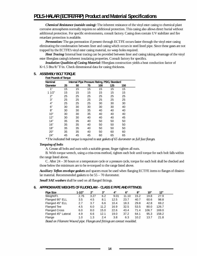
5. ASSEMBLY BOLT TORQUEFoot Pounds of TorqueNominal Internal Pipe Pressure Rating, PSIG, StandardDiameter 25 50 75 100 125 150
1” 15 15 15 15 15 151 1/2” 15 15 15 15 15 15
2” 25 25 25 25 25 253” 25 25 25 25 25 254” 25 25 25 30 30 306” 30 30 30 30 30 408” 30 30 35 40 40 40
10” 30 30 35 40 40 4012” 30 30 40 40 40 4514” 35 35 40 50 50 5016” 35 35 40 50 50 5018” 35 35 40 50 50 5020” 35 35 40 50 60 6024” 45 45 45 60 65 65
* The indicated bolt torque is required to seat gaskets of 65 durometer on full face flanges.
Torquing of boltsA. Grease all bolts and nuts with a suitable grease, finger tighten all nuts.B. With torque wrench, using a criss-cross method, tighten each bolt until torque for each bolt falls within
the range listed above.C. After 24 – 30 hours or a temperature cycle or a pressure cycle, torque for each bolt shall be checked and
those below the minimum are to be re-torqued to the range listed above.
Auxiliary Teflon envelope gaskets and spacers must be used when flanging ECTFE items to flanges of dissimi-lar material. Recommended gaskets to be 55 – 70 durometer.
Small SAE washers shall be used on all flanged fittings.
6. APPROXIMATE WEIGHTS OF FLUOROLAM - CLASS E PIPE AND FITTINGS:Pipe Size 1-1/2” 2” 3” 4” 6” 8” 10” 12”Weight/Ft. 2.76 3.27 6.2 9.01 11.10 15.2 19.8 27.9Flanged 90° ELL 3.5 4.5 8.1 12.5 23.7 40.7 60.6 98.8Flanged 45° ELL 2.7 3.7 6.6 10.4 18.3 29.8 42.8 69.2Flanged Tee 4.5 6.0 11.2 16.9 32.5 53.5 80.0 126.7Flanged Cross 6.0 8.0 15.0 22.6 43.4 71.4 106.7 169.0Flanged 45° Lateral 4.9 6.6 12.1 19.0 37.2 64.1 95.3 158.2Flange 1.0 1.3 2.4 3.8 6.3 10.2 13.7 21.8Based on Filament Wound pipe. Flanges and fittings are contact moulded.
15
PDLS-HALAR (ECTFE/FRP) Product and Material Specifications
7. FLUOROLAM-CLASS E INSTALLATION PROCEDURESA. Select gasket material of correct durometer and thickness.B. Use a spacer when bolting FLUOROLAM-CLASS E flanges to flanges of dissimilar material.C. Use small SAE washers on all FLUOROLAM-CLASS E flanges.D. Lubricate all bolts before tightening.E. Tighten all bolts using criss-cross bolting method.F. Using a torque wrench, tighten bolts to bolt torques specified in Section 8..G. Allow bolts to seat for 24 hours and recheck bolt torques.* On flanges <4”, tighten in increments of 5 ft. lbs.* On flanges >6”, tighten in increments of 10 ft. lbs.
8. For all fittings and dimensional drawings, such as 90˚ Elbows, 45˚ Elbows and Concentric Reducers,Contact Prolite Engineering.
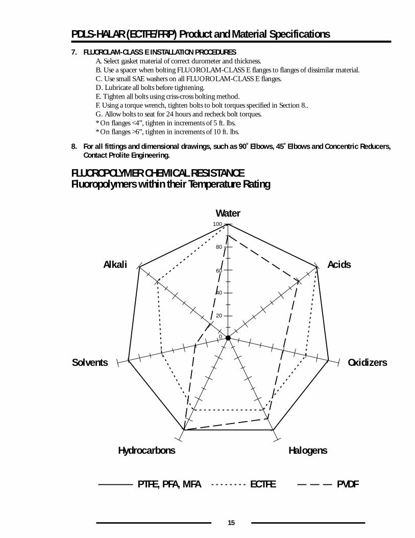
FLUOROPOLYMER CHEMICAL RESISTANCEFluoropolymers within their Temperature Rating
Hydrocarbons
PTFE, PFA, MFA ECTFE PVDF
Water
Halogens
Solvents Oxidizers
Alkali Acids
0
20
40
60
80
100
16
PDLS MFA/FRP Product and Material SpecificationsPRODUCT SPECIFICATIONS #APP 1998PDLS (MFA/FRP) and FLUOROLAM-CLASS M PIPING
A. ADVANTAGES OF MFAHyflon MFA fluoropolymers offer the highest temperature rating and broadest chemical resistance of all
melt processable fluoropolymers. They are an ideal choice for extreme thermal and chemical environments.Hyflon MFA is designed to give much better physical properties than FEP, lower creep, and improved stresscracking resistance, and has a 50˚C higher temperature rating. Hyflon grades are also lower in permeation thancomparable competitive products.
Because its structure is based on PFA chemistry, Hyflon MFA offers an excellent balance of properties forlining applications. The unique chemistry of MFA allows for a very cost competitive product, giving PFA typeperformance with improved economics. It combines the best properties of both FEP and PFA while maintain-ing a cost similar to FEP. Upper temperature rating is high, 260˚C, like PFA, surface is extremely smooth(much smoother than PFA), low temperature mechanical properties are similar to FEP and better than PFA.MFA’s excellent thermal stability has allowed its use in semiconductor high purity chemical applications wheretraditionally high purity PFA was used. All things considered, MFA offers the best balance of properties forlining applications than any other melt processible perfluoropolymer.
Easily extruded for pipe, tubing and injection moulded for fittings, Prolite believes MFA the best newmaterial in Dualaminate construction for beyond the year 2000.
B. APPLICATIONS OF MFAHyflon MFA is the first new fluoropolymer to the plastics industry in over 20 years and, since its introduction
in 1995, has gained rapid acceptance in the chemical processing, pulp and paper, and high purity processingindustries. Hyflon MFA is resistant to virtually all chemistries, even the most extreme, including acids, bases,oxidizing acids, mineral acids, metal salt solutions, peroxides and more.
• Scrubbing towers handling sodium chlorate and hydrogen gas• Waste stripping columns• High purity chemical storage tanks and process equipment• Chemical transport containers• High purity piping systems (thermoplastic and Dualaminate).
C. OTHER FLUOROPOLYMERS AVAILABLEFor special applications, Prolite will use FEP, PFA or ETFE (Tefzel) in Dualaminate pipe construction.
Contact Prolite Engineering for details.
1. SCOPEThis classification provides design information applicable to FLUOROLAM - CLASS M Dual Laminate
piping. These products include pipe spools, fittings and fabrications.
2. MATERIALSLiner
Ausimont Co-Polymer MFA resins are used in the manufacture of linings from pipe fittings. The resinmeets the requirements of ASTM D 6314.
Property Value TestSpecific Gravity 2.12 – 2.17 ASTM D792Tensile Strength (PSI) 2700 – 3600 ASTM D638Elongation 300 – 360 ASTM D638
Bonding LayerUsing a melting process a knit fiberglass cloth is melt bonded and partially mechanically embedded into
the O.D. surface of the MFA liner. Bond strength between MFA and fiberglass is:A. Shear Strength as per DIN Test Method 53769 Part 1.B. Peel Strength as per ASTM D-1781-98.
17
PDLS MFA/FRP Product and Material Specifications
Outer CasingThe MFA bonding composite layer is reinforced by hand lay up or filament wound thicknesses. Hand lay
up construction when performed is per product standard NBS PS-15-69. A premium Vinylester grade resin isused with glass reinforcement and U.U. stabilized gel coat.
3. DESIGN AND FABRICATION DETAILSDimensional drawings included in paragraph 8 of this specification pertain to products listed in paragraph 1.Flanges for pipe spools and fitting shall have bolt circle diameters, hole diameter and number of bolt holes
in accordance with ANSI B 16.5 unless otherwise specified.Pipe and fittings fabrication tolerances are as follows:
Item Dimension TolerancesPipe spools Length ± 1/8”
Bolt hole alignment ± 1/16”Flange alignment ± 1/32” (1” thru 4”)(with theoretic pipe ± 3/64” (> 6”)centreline)
Flanges All dimensions ANSI B 16.5except thickness
Fittings Face to centerline ± 1/8”Flange alignment ± 1/32” (1” thru 4”)(with theoretic pipe ± 3/64” (> 6”)centreline)
I.D. Radius Flanges 1/4” ± 1/16”
4. APPLICATION AND OPERATIONAL PARAMETERSTemperature Range: FLUOROLAM - CLASS M is suitable for 250˚F to - 20˚F unless otherwise specified.Pressure Range: Continuous operation from full vacuum to 150 PSI.Thermal expansion and contraction: 1.7 x 10⁻⁵/in/in/˚FChemical Resistance (liner): MFA is chemically inert to all concentrated acids, alkalies, many organics.Chemical Resistance (outside casing): Premium Grade Vinylester to contain UV protection and fire
retardant if required.Permeation: Superior to FEP, PVDF and PTFE. For specifics, contact Prolite.Heat Tracing: Internal heat tracing can be provided between liner and casing taking advantage of the vinyl
ester fiberglass casing’s inherent insulating properties. Consult factory for specifics.Insulation Qualities of Casing Material: Fiberglass construction yields a heat conduction factor of
K=1.5 Btu/ft/˚F/in. Check dimensional data for casing thickness.
5. ASSEMBLY BOLT TORQUEFoot Pounds of TorqueNominal Internal Pipe Pressure Rating, PSIG, StandardDiameter 25 50 75 100 125 150
1” 15 15 15 15 15 151 1/2” 15 15 15 15 15 15
2” 25 25 25 25 25 253” 25 25 25 25 25 254” 25 25 25 30 30 306” 30 30 30 30 30 408” 30 30 35 40 40 4010” 30 30 35 40 40 4012” 30 30 40 40 40 4514” 35 35 40 50 50 5016” 35 35 40 50 50 5018” 35 35 40 50 50 5020” 35 35 40 50 60 6024” 45 45 45 60 65 65
* The indicated bolt torque is required to seat gaskets of 65 durometer on full face flanges.
18
Torquing of boltsA. Grease all bolts and nuts with a suitable grease, finger tighten all nuts.B. With torque wrench, using a criss-cross method, tighten each bolt until torque for each bolt falls within
the range listed above.C. After 24 – 30 hours or a temperature cycle or a pressure cycle, torque for each bolt shall be checked and
those below the minimum are to be re-torqued to the range listed above.
Auxiliary Teflon envelope gaskets and spacers must be used when flanging MFA items to flanges of dissimilarmaterial. Recommended gaskets to be 55 – 70 durometer.
Small SAE washers shall be used on all flanged fittings.
6. APPROXIMATE WEIGHTS OF FLUOROLAM-CLASS M PIPE AND FITTINGS:Pipe Size 1-1/2” 2” 3” 4” 6” 8” 10” 12”Weight/Ft. 2.76 3.27 6.2 9.01 11.1 15.2 19.8 27.9Flanged 90° ELL 3.5 4.5 8.1 12.5 23.7 40.7 60.6 98.8Flanged 45° ELL 2.7 3.7 6.6 10.4 18.3 29.8 42.8 69.2Flanged Tee 4.5 6.0 11.2 16.9 32.5 53.5 80.0 126.7Flanged Cross 6.0 8.0 15.0 22.6 43.4 71.4 106.7 169.0Flanged 45° Lateral 4.9 6.6 12.1 19.0 37.2 64.1 95.3 158.2Flange 1.0 1.3 2.4 3.8 6.3 10.2 13.7 21.8Based on Filament Wound pipe. Flanges and fittings are contact moulded.
7. MFA INSTALLATION PROCEDURESA. Select gasket material of correct durometer and thickness.B. Use a spacer when bolting FLUOROLAM - CLASS M flanges to flanges of dissimilar material.C. Use small SAE washers on all FLUOROLAM - CLASS M flanges.D. Lubricate all bolts before tightening.E. Tighten all bolts using criss-cross bolting method.F. Using a torque wrench, tighten bolts to bolt torques specified in Section 8..G. Allow bolts to seat for 24 hours and recheck bolt torques.* On flanges <4”, tighten in increments of 5 ft. lbs.* On flanges >6”, tighten in increments of 10 ft. lbs.
8. For all fittings and dimensional drawings, such as 90˚ Elbows, 45˚ Elbows and Concentric Reducers,Contact Prolite Engineering.
PDLS MFA/FRP Product and Material Specifications
19
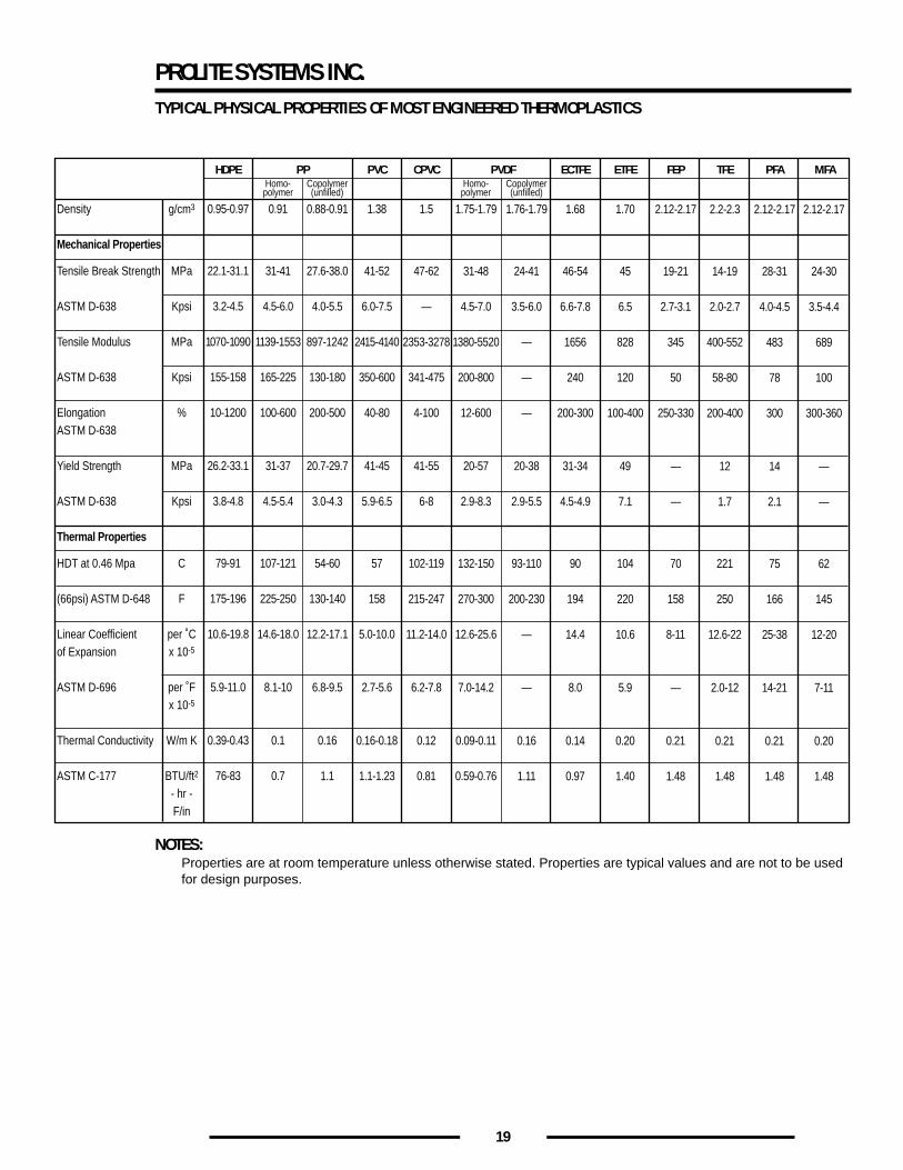
PROLITE SYSTEMS INC.TYPICAL PHYSICAL PROPERTIES OF MOST ENGINEERED THERMOPLASTICS
NOTES:Properties are at room temperature unless otherwise stated. Properties are typical values and are not to be usedfor design purposes.
HDPE PPHomo-polymer
Copolymer(unfilled)
Homo-polymer
Copolymer(unfilled)
PVC CPVC PVDF ECTFE FEP TFE PFA MFAETFE
Density
Mechanical Properties
Tensile Break Strength
ASTM D-638
Tensile Modulus
ASTM D-638
ElongationASTM D-638
Yield Strength
ASTM D-638
Thermal Properties
HDT at 0.46 Mpa
(66psi) ASTM D-648
Linear Coefficientof Expansion
ASTM D-696
Thermal Conductivity
ASTM C-177
g/cm3
MPa
Kpsi
MPa
Kpsi
%
MPa
Kpsi
C
F
per ˚Cx 10-5
per ˚Fx 10-5
W/m K
BTU/ft2
- hr -F/in
0.95-0.97
22.1-31.1
3.2-4.5
1070-1090
155-158
10-1200
26.2-33.1
3.8-4.8
79-91
175-196
10.6-19.8
5.9-11.0
0.39-0.43
76-83
0.91
31-41
4.5-6.0
1139-1553
165-225
100-600
31-37
4.5-5.4
107-121
225-250
14.6-18.0
8.1-10
0.1
0.7
0.88-0.91
27.6-38.0
4.0-5.5
897-1242
130-180
200-500
20.7-29.7
3.0-4.3
54-60
130-140
12.2-17.1
6.8-9.5
0.16
1.1
1.38
41-52
6.0-7.5
2415-4140
350-600
40-80
41-45
5.9-6.5
57
158
5.0-10.0
2.7-5.6
0.16-0.18
1.1-1.23
1.5
47-62
—
2353-3278
341-475
4-100
41-55
6-8
102-119
215-247
11.2-14.0
6.2-7.8
0.12
0.81
1.75-1.79
31-48
4.5-7.0
1380-5520
200-800
12-600
20-57
2.9-8.3
132-150
270-300
12.6-25.6
7.0-14.2
0.09-0.11
0.59-0.76
1.76-1.79
24-41
3.5-6.0
—
—
—
20-38
2.9-5.5
93-110
200-230
—
—
0.16
1.11
1.68
46-54
6.6-7.8
1656
240
200-300
31-34
4.5-4.9
90
194
14.4
8.0
0.14
0.97
1.70
45
6.5
828
120
100-400
49
7.1
104
220
10.6
5.9
0.20
1.40
2.12-2.17
19-21
2.7-3.1
345
50
250-330
—
—
70
158
8-11
—
0.21
1.48
2.2-2.3
14-19
2.0-2.7
400-552
58-80
200-400
12
1.7
221
250
12.6-22
2.0-12
0.21
1.48
2.12-2.17
28-31
4.0-4.5
483
78
300
14
2.1
75
166
25-38
14-21
0.21
1.48
2.12-2.17
24-30
3.5-4.4
689
100
300-360
—
—
62
145
12-20
7-11
0.20
1.48
20
1. INSPECTION1. Prior to any fabrication, all thermoplastic liners/pipe are fully inspected for total integrity.
No cracks, pinholes occlusions etc. are permitted.2. Fabricated fittings are electrostatically tested to max. 15,000 volts for integrity.3. Fiberglass outer reinforcement is checked for flaws, colour mismatch and for total curing of the resin used.
2. HANDLING AND SHIPPINGThe gasket face of each spool or fitting shall be protected by end plates or other suitable protective means.All spools and fittings shall be suitably packed to provide necessary protection during handling, shipping
and storage.
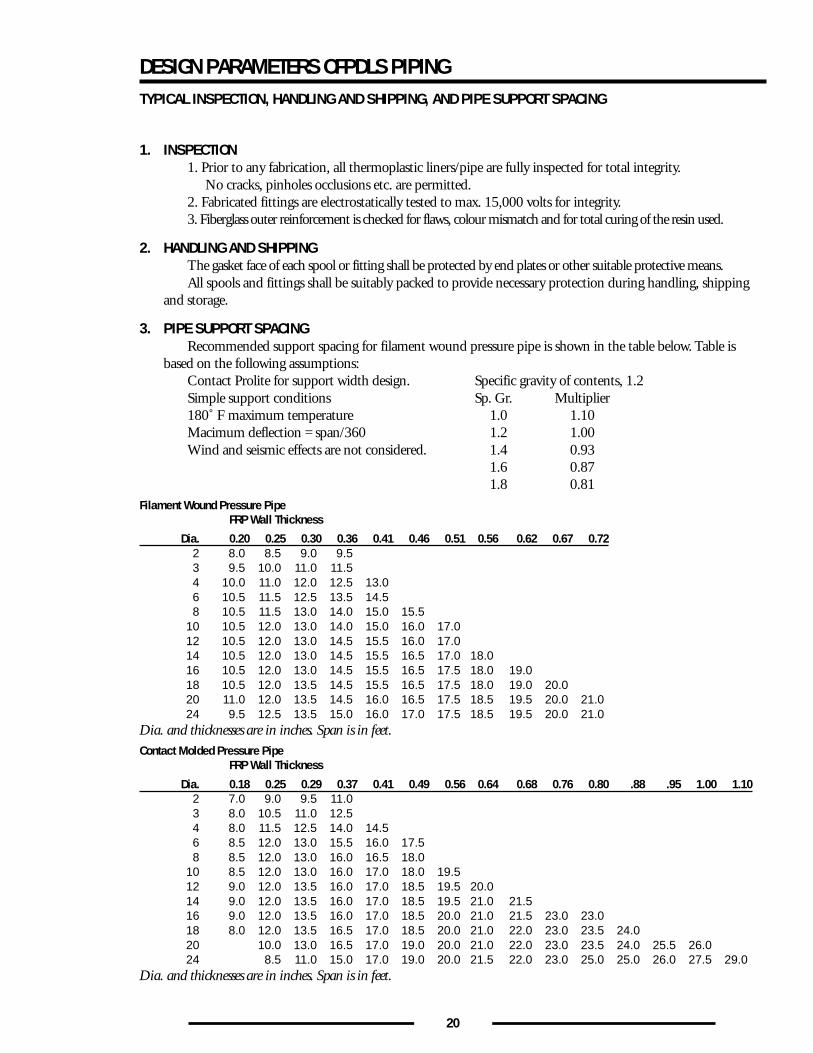
3. PIPE SUPPORT SPACINGRecommended support spacing for filament wound pressure pipe is shown in the table below. Table is
based on the following assumptions:Contact Prolite for support width design. Specific gravity of contents, 1.2Simple support conditions Sp. Gr. Multiplier180˚ F maximum temperature 1.0 1.10Macimum deflection = span/360 1.2 1.00Wind and seismic effects are not considered. 1.4 0.93
1.6 0.871.8 0.81
Filament Wound Pressure PipeFRP Wall Thickness
Dia. 0.20 0.25 0.30 0.36 0.41 0.46 0.51 0.56 0.62 0.67 0.722 8.0 8.5 9.0 9.53 9.5 10.0 11.0 11.54 10.0 11.0 12.0 12.5 13.06 10.5 11.5 12.5 13.5 14.58 10.5 11.5 13.0 14.0 15.0 15.5
10 10.5 12.0 13.0 14.0 15.0 16.0 17.012 10.5 12.0 13.0 14.5 15.5 16.0 17.014 10.5 12.0 13.0 14.5 15.5 16.5 17.0 18.016 10.5 12.0 13.0 14.5 15.5 16.5 17.5 18.0 19.018 10.5 12.0 13.5 14.5 15.5 16.5 17.5 18.0 19.0 20.020 11.0 12.0 13.5 14.5 16.0 16.5 17.5 18.5 19.5 20.0 21.024 9.5 12.5 13.5 15.0 16.0 17.0 17.5 18.5 19.5 20.0 21.0
Dia. and thicknesses are in inches. Span is in feet.Contact Molded Pressure Pipe
FRP Wall Thickness
Dia. 0.18 0.25 0.29 0.37 0.41 0.49 0.56 0.64 0.68 0.76 0.80 .88 .95 1.00 1.102 7.0 9.0 9.5 11.03 8.0 10.5 11.0 12.54 8.0 11.5 12.5 14.0 14.56 8.5 12.0 13.0 15.5 16.0 17.58 8.5 12.0 13.0 16.0 16.5 18.0
10 8.5 12.0 13.0 16.0 17.0 18.0 19.512 9.0 12.0 13.5 16.0 17.0 18.5 19.5 20.014 9.0 12.0 13.5 16.0 17.0 18.5 19.5 21.0 21.516 9.0 12.0 13.5 16.0 17.0 18.5 20.0 21.0 21.5 23.0 23.018 8.0 12.0 13.5 16.5 17.0 18.5 20.0 21.0 22.0 23.0 23.5 24.020 10.0 13.0 16.5 17.0 19.0 20.0 21.0 22.0 23.0 23.5 24.0 25.5 26.024 8.5 11.0 15.0 17.0 19.0 20.0 21.5 22.0 23.0 25.0 25.0 26.0 27.5 29.0
Dia. and thicknesses are in inches. Span is in feet.
DESIGN PARAMETERS OFPDLS PIPINGTYPICAL INSPECTION, HANDLING AND SHIPPING, AND PIPE SUPPORT SPACING
21
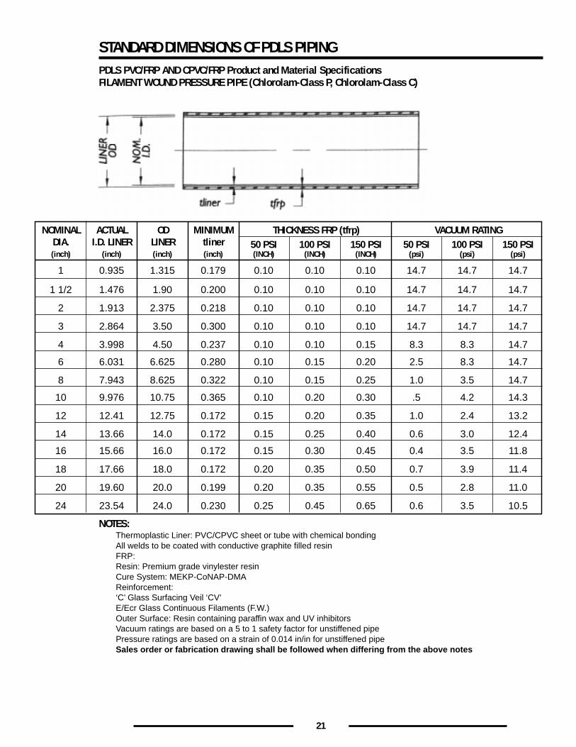
STANDARD DIMENSIONS OF PDLS PIPINGPDLS PVC/FRP AND CPVC/FRP Product and Material SpecificationsFILAMENT WOUND PRESSURE PIPE (Chlorolam-Class P, Chlorolam-Class C)
NOTES:Thermoplastic Liner: PVC/CPVC sheet or tube with chemical bondingAll welds to be coated with conductive graphite filled resinFRP:Resin: Premium grade vinylester resinCure System: MEKP-CoNAP-DMAReinforcement:‘C’ Glass Surfacing Veil ‘CV’E/Ecr Glass Continuous Filaments (F.W.)Outer Surface: Resin containing paraffin wax and UV inhibitorsVacuum ratings are based on a 5 to 1 safety factor for unstiffened pipePressure ratings are based on a strain of 0.014 in/in for unstiffened pipeSales order or fabrication drawing shall be followed when differing from the above notes
NOMINALDIA.
ACTUALI.D. LINER
ODLINER
MINIMUMtliner
THICKNESS FRP (tfrp) VACUUM RATING50 PSI 100 PSI 150 PSI 50 PSI 100 PSI 150 PSI
1 0.935 1.315 0.179 0.10 0.10 0.10 14.7 14.7 14.7
1 1/2 1.476 1.90 0.200 0.10 0.10 0.10 14.7 14.7 14.7
2 1.913 2.375 0.218 0.10 0.10 0.10 14.7 14.7 14.7
3 2.864 3.50 0.300 0.10 0.10 0.10 14.7 14.7 14.7
4 3.998 4.50 0.237 0.10 0.10 0.15 8.3 8.3 14.7
6 6.031 6.625 0.280 0.10 0.15 0.20 2.5 8.3 14.7
8 7.943 8.625 0.322 0.10 0.15 0.25 1.0 3.5 14.7
10 9.976 10.75 0.365 0.10 0.20 0.30 .5 4.2 14.3
12 12.41 12.75 0.172 0.15 0.20 0.35 1.0 2.4 13.2
14 13.66 14.0 0.172 0.15 0.25 0.40 0.6 3.0 12.4
18 17.66 18.0 0.172 0.20 0.35 0.50 0.7 3.9 11.4
16 15.66 16.0 0.172 0.15 0.30 0.45 0.4 3.5 11.8
20 19.60 20.0 0.199 0.20 0.35 0.55 0.5 2.8 11.0
24 23.54 24.0 0.230 0.25 0.45 0.65 0.6 3.5 10.5
(inch) (inch) (inch) (inch) (INCH) (INCH) (INCH) (psi) (psi) (psi)
22
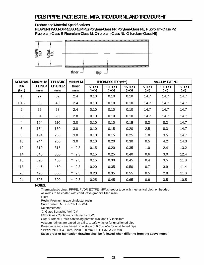
PDLS PP/PE, PVDF, ECTFE , MFA, TROVIDUR NL AND TROVIDUR HTProduct and Material SpecificationsFILAMENT WOUND PRESSURE PIPE (Polylam-Class PP, Polylam-Class PE, Fluorolam-Class PV,Fluorolam-Class E, Fluorolam-Class M, Chlorolam-Class NL, Chlorolam-Class HT)
NOTES:Thermoplastic Liner: PP/PE, PVDF, ECTFE, MFA sheet or tube with mechanical cloth embeddedAll welds to be coated with conductive graphite filled resinFRP:Resin: Premium grade vinylester resinCure System: MEKP-CoNAP-DMAReinforcement:‘C’ Glass Surfacing Veil ‘CV’E/Ecr Glass Continuous Filaments (F.W.)Outer Surface: Resin containing paraffin wax and UV inhibitorsVacuum ratings are based on a 5 to 1 safety factor for unstiffened pipePressure ratings are based on a strain of 0.014 in/in for unstiffened pipe* PP/PE/NL/HT 4.0 mm, PVDF 3.0 mm, ECTFE/MFA 2.3 mmSales order or fabrication drawing shall be followed when differing from the above notes
NOMINALDIA.
MAXIMUMI.D. LINER
T PLASTICOD LINER
MINIMUMtliner
THICKNESS FRP (tfrp) VACUUM RATING50 PSI 100 PSI 150 PSI 50 PSI 100 PSI 150 PSI
1 27 32 2.4 0.10 0.10 0.10 14.7 14.7 14.7
1 1/2 35 40 2.4 0.10 0.10 0.10 14.7 14.7 14.7
2 56 63 2.4 0.10 0.10 0.10 14.7 14.7 14.7
3 84 90 2.8 0.10 0.10 0.10 14.7 14.7 14.7
4 104 110 3.0 0.10 0.10 0.15 8.3 8.3 14.7
6 154 160 3.0 0.10 0.15 0.20 2.5 8.3 14.7
8 194 200 3.0 0.10 0.15 0.25 1.0 3.5 14.7
10 244 250 3.0 0.10 0.20 0.30 0.5 4.2 14.3
12 310 315 2.3*
*
*
*
*
*
0.15 0.20 0.35 1.0 2.4 13.2
14 345 350 2.3 0.15 0.25 0.40 0.6 3.0 12.4
18 445 450 2.3 0.20 0.35 0.50 0.7 3.9 11.4
16 395 400 2.3 0.15 0.30 0.45 0.4 3.5 11.8
20 495 500 2.3 0.20 0.35 0.55 0.5 2.8 11.0
24 595 600 2.3 0.25 0.45 0.65 0.6 3.5 10.5
(inch) (mm) (mm) (mm) (INCH) (INCH) (INCH) (psi) (psi) (psi)
23
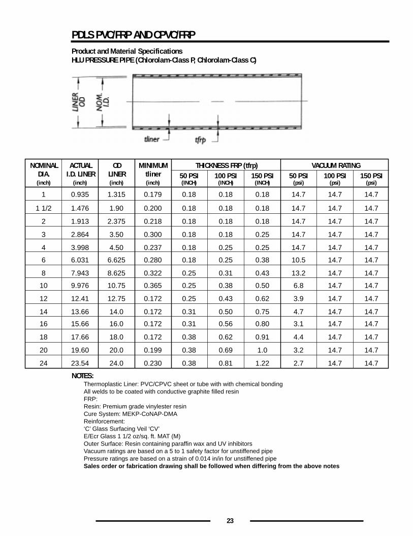
PDLS PVC/FRP AND CPVC/FRPProduct and Material SpecificationsHLU PRESSURE PIPE (Chlorolam-Class P, Chlorolam-Class C)
NOTES:Thermoplastic Liner: PVC/CPVC sheet or tube with with chemical bondingAll welds to be coated with conductive graphite filled resinFRP:Resin: Premium grade vinylester resinCure System: MEKP-CoNAP-DMAReinforcement:‘C’ Glass Surfacing Veil ‘CV’E/Ecr Glass 1 1/2 oz/sq. ft. MAT (M)Outer Surface: Resin containing paraffin wax and UV inhibitorsVacuum ratings are based on a 5 to 1 safety factor for unstiffened pipePressure ratings are based on a strain of 0.014 in/in for unstiffened pipeSales order or fabrication drawing shall be followed when differing from the above notes
NOMINALDIA.
ACTUALI.D. LINER
ODLINER
MINIMUMtliner
THICKNESS FRP (tfrp) VACUUM RATING50 PSI 100 PSI 150 PSI 50 PSI 100 PSI 150 PSI
1 0.935 1.315 0.179 0.18 0.18 0.18 14.7 14.7 14.7
1 1/2 1.476 1.90 0.200 0.18 0.18 0.18 14.7 14.7 14.7
2 1.913 2.375 0.218 0.18 0.18 0.18 14.7 14.7 14.7
3 2.864 3.50 0.300 0.18 0.18 0.25 14.7 14.7 14.7
4 3.998 4.50 0.237 0.18 0.25 0.25 14.7 14.7 14.7
6 6.031 6.625 0.280 0.18 0.25 0.38 10.5 14.7 14.7
8 7.943 8.625 0.322 0.25 0.31 0.43 13.2 14.7 14.7
10 9.976 10.75 0.365 0.25 0.38 0.50 6.8 14.7 14.7
12 12.41 12.75 0.172 0.25 0.43 0.62 3.9 14.7 14.7
14 13.66 14.0 0.172 0.31 0.50 0.75 4.7 14.7 14.7
18 17.66 18.0 0.172 0.38 0.62 0.91 4.4 14.7 14.7
16 15.66 16.0 0.172 0.31 0.56 0.80 3.1 14.7 14.7
20 19.60 20.0 0.199 0.38 0.69 1.0 3.2 14.7 14.7
24 23.54 24.0 0.230 0.38 0.81 1.22 2.7 14.7 14.7
(inch) (inch) (inch) (inch) (INCH) (INCH) (INCH) (psi) (psi) (psi)
24
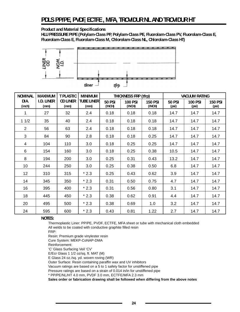
PDLS PP/PE, PVDF, ECTFE , MFA, TROVIDUR NL AND TROVIDUR HTProduct and Material SpecificationsHLU PRESSURE PIPE (Polylam-Class PP, Polylam-Class PE, Fluorolam-Class PV, Fluorolam-Class E,Fluorolam-Class E, Fluorolam-Class M, Chlorolam-Class NL, Chlorolam-Class HT)
NOTES:Thermoplastic Liner: PP/PE, PVDF, ECTFE, MFA sheet or tube with mechanical cloth embeddedAll welds to be coated with conductive graphite filled resinFRP:Resin: Premium grade vinylester resinCure System: MEKP-CoNAP-DMAReinforcement:‘C’ Glass Surfacing Veil ‘CV’E/Ecr Glass 1 1/2 oz/sq. ft. MAT (M)E Glass 24 oz./sq. yd. woven roving (WR)Outer Surface: Resin containing paraffin wax and UV inhibitorsVacuum ratings are based on a 5 to 1 safety factor for unstiffened pipePressure ratings are based on a strain of 0.014 in/in for unstiffened pipe* PP/PE/NL/HT 4.0 mm, PVDF 3.0 mm, ECTFE/MFA 2.3 mmSales order or fabrication drawing shall be followed when differing from the above notes
NOMINALDIA.
MAXIMUMI.D. LINER
T PLASTICOD LINER
MINIMUMTUBE LINER
THICKNESS FRP (tfrp) VACUUM RATING50 PSI 100 PSI 150 PSI 50 PSI 100 PSI 150 PSI
1 32 2.4 0.18 0.18 0.18 14.7 14.7 14.7
1 1/2 40 2.4 0.18 0.18 0.18 14.7 14.7 14.7
2 63 2.4 0.18 0.18 0.18 14.7 14.7 14.7
3 90 2.8 0.18 0.18 0.25 14.7 14.7 14.7
4 110 3.0 0.18 0.25 0.25 14.7 14.7 14.7
6 160 3.0 0.18 0.25 0.38 10.5 14.7 14.7
8 200 3.0 0.25 0.31 0.43 13.2 14.7 14.7
10 250 3.0 0.25 0.38 0.50 6.8 14.7 14.7
12 315 0.25 0.43 0.62 3.9 14.7 14.7
14 350 0.31 0.50 0.75 4.7 14.7 14.7
18 450 0.38 0.62 0.91 4.4 14.7 14.7
16 400 0.31 0.56 0.80 3.1 14.7 14.7
20 500 0.38 0.69 1.0 3.2 14.7 14.7
24 600 0.43 0.81 1.22 2.7 14.7 14.7
(inch) (mm) (mm) (mm) (INCH) (INCH) (INCH) (psi) (psi) (psi)
27
35
56
84
104
154
194
244
310
345
445
395
495
595
2.3*
*
*
*
*
*
2.3
2.3
2.3
2.3
2.3
25
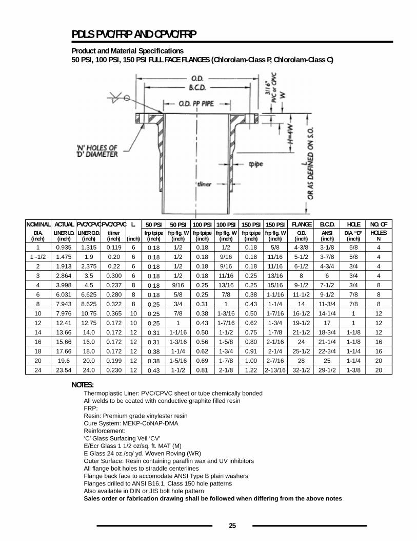
PDLS PVC/FRP AND CPVC/FRPProduct and Material Specifications50 PSI, 100 PSI, 150 PSI FULL FACE FLANGES (Chlorolam-Class P, Chlorolam-Class C)
NOTES:Thermoplastic Liner: PVC/CPVC sheet or tube chemically bondedAll welds to be coated with conductive graphite filled resinFRP:Resin: Premium grade vinylester resinCure System: MEKP-CoNAP-DMAReinforcement:‘C’ Glass Surfacing Veil ‘CV’E/Ecr Glass 1 1/2 oz/sq. ft. MAT (M)E Glass 24 oz./sq/ yd. Woven Roving (WR)Outer Surface: Resin containing paraffin wax and UV inhibitorsAll flange bolt holes to straddle centerlinesFlange back face to accomodate ANSI Type B plain washersFlanges drilled to ANSI B16.1, Class 150 hole patternsAlso available in DIN or JIS bolt hole patternSales order or fabrication drawing shall be followed when differing from the above notes
NOMINAL ACTUAL PVC/CPVC PVC/CPVCDIA. LINER I.D. LINER O.D. tliner frp tpipe frp flg. W
50 PSI 50 PSI
1 0.935 1.315 0.119 1/20.18
(inch) (inch) (inch) (inch)
L.
6(inch) (inch) (inch)
1 -1/2 1.475 1.9 0.20 1/20.186
2 1.913 2.375 0.22 1/20.186
3 2.864 3.5 0.300 1/20.186
4 3.998 4.5 0.237 9/160.188
6 6.031 6.625 0.280 5/80.188
8 7.943 8.625 0.322 3/40.258
10 7.976 10.75 0.365 7/80.2510
12 12.41 12.75 0.172 10.2510
14 13.66 14.0 0.172 1-1/160.3112
16 15.66 16.0 0.172 1-3/160.3112
18 17.66 18.0 0.172 1-1/40.3812
20 19.6 20.0 0.199 1-5/160.3812
24 23.54 24.0 0.230
FLANGE B.C.D. HOLE NO. OFO.D. ANSI DIA. “D” HOLES
4-3/8 3-1/8 5/8 4(inch) (inch) (inch) N
5-1/2 3-7/8 5/8 4
6-1/2 4-3/4 3/4 4
8 6 3/4 4
9-1/2 7-1/2 3/4 8
11-1/2 9-1/2 7/8 8
14 11-3/4 7/8 8
16-1/2 14-1/4 1 12
19-1/2 17 1 12
21-1/2 18-3/4 1-1/8 12
24 21-1/4 1-1/8 16
25-1/2 22-3/4 1-1/4 16
28 25 1-1/4 20
32-1/2 29-1/2 1-3/8 201-1/20.4312
frp tpipe frp flg. W100 PSI 100 PSI
1/2 0.18(inch) (inch)
9/16 0.18
9/16 0.18
11/16 0.25
13/16 0.25
7/8 0.38
1 0.43
1-3/16 0.50
1-7/16 0.62
1-1/2 0.75
1-5/8 0.80
1-3/4 0.91
1-7/8 1.00
2-1/8
5/8
11/16
11/16
13/16
15/16
1-1/16
1-1/4
1-7/16
1-3/4
1-7/8
2-1/16
2-1/4
2-7/16
2-13/161.22
0.18
0.18
0.18
0.18
0.25
0.25
0.31
0.38
0.43
0.50
0.56
0.62
0.69
0.81
frp tpipe frp flg. W150 PSI 150 PSI
(inch) (inch)
26
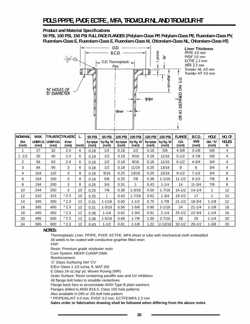
NOTES:Thermoplastic Liner: PP/PE, PVDF, ECTFE, MFA sheet or tube with mechanical cloth embeddedAll welds to be coated with conductive graphite filled resinFRP:Resin: Premium grade vinylester resinCure System: MEKP-CoNAP-DMAReinforcement:‘C’ Glass Surfacing Veil ‘CV’E/Ecr Glass 1 1/2 oz/sq. ft. MAT (M)E Glass 24 oz./sq/ yd. Woven Roving (WR)Outer Surface: Resin containing paraffin wax and UV inhibitorsAll flange bolt holes to straddle centerlinesFlange back face to accomodate ANSI Type B plain washersFlanges drilled to ANSI B16.5, Class 150 hole patternsAlso available in DIN or JIS bolt hole pattern* PP/PE/NL/HT 4.0 mm, PVDF 3.0 mm, ECTFE/MFA 2.3 mmSales order or fabrication drawing shall be followed when differing from the above notes
NOMINAL MAX. T PLASTICT PLASTICDIA. LINER I.D. LINER O.D. tliner frp tpipe frp flg. W
50 PSI 50 PSI
1 27 32 2.4 1/20.18
(inch) (mm) (mm) (mm)
L.
6(inch) (inch) (inch)
1 -1/2 35 40 2.4 1/20.186
2 56 63 2.4 1/20.186
3 84 90 3 1/20.186
4 104 110 3 9/160.188
6 154 160 3 5/80.188
8 194 200 3 3/40.258
10 244 250 3 7/80.2510
12 310 315 2.3*
*
*
*
*
*
10.2510
14 345 350 2.3 1-1/160.3112
16 395 400 2.3 1-3/160.3112
18 445 450 2.3 1-1/40.3812
20 495 500 2.3 1-5/160.3812
24 595 600 2.3
FLANGE B.C.D. HOLE NO. OFO.D. DIA. “D” HOLES
4-3/8 3-1/8 5/8 4(inch) (inch) (inch) N
5-1/2 3-7/8 5/8 4
6-1/2 4-3/4 3/4 4
8 6 3/4 4
9-1/2 7-1/2 3/4 8
11-1/2 9-1/2 7/8 8
14 11-3/4 7/8 8
16-1/2 14-1/4 1 12
19-1/2 17 1 12
21-1/2 18-3/4 1-1/8 12
24 21-1/4 1-1/8 16
25-1/2 22-3/4 1-1/4 16
28 25 1-1/4 20
32-1/2 29-1/2 1-3/8 201-1/20.4312
frp tpipe frp flg. W100 PSI 100 PSI
1/2 0.18(inch) (inch)
9/16 0.18
9/16 0.18
11/16 0.25
13/16 0.25
7/8 0.38
1 0.43
1-3/16 0.50
1-7/16 0.62
1-1/2 0.75
1-5/8 0.80
1-3/4 0.91
1-7/8 1.00
2-1/8
5/8
11/16
11/16
13/16
15/16
1-1/16
1-1/4
1-7/16
1-3/4
1-7/8
2-1/16
2-1/4
2-7/16
2-13/161.22
0.18
0.18
0.18
0.18
0.25
0.25
0.31
0.38
0.43
0.50
0.56
0.62
0.69
0.81
frp tpipe frp flg. W150 PSI 150 PSI
(inch) (inch)ANSI
PDLS PP/PE, PVDF, ECTFE , MFA, TROVIDUR NL AND TROVIDUR HTProduct and Material Specifications50 PSI, 100 PSI, 150 PSI FULL FACE FLANGES (Polylam-Class PP, Polylam-Class PE, Fluorolam-Class PV,Fluorolam-Class E, Fluorolam-Class E, Fluorolam-Class M, Chlorolam-Class NL, Chlorolam-Class HT)
27
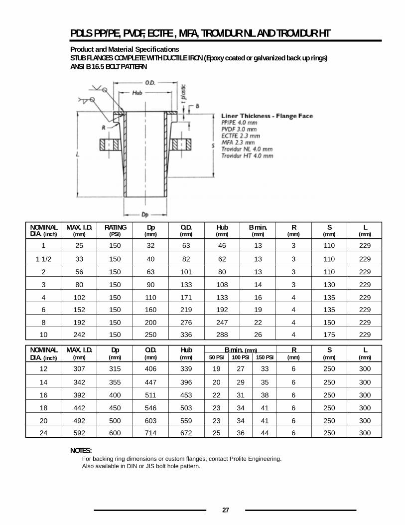
NOTES:For backing ring dimensions or custom flanges, contact Prolite Engineering.Also available in DIN or JIS bolt hole pattern.
NOMINAL MAX. I.D. RATING Dp O.D. Hub B min. R S L
1 25 150 32 63 46 13 3 110 229
1 1/2 33 150 40 82 62 13 3 110 229
2 56 150 63 101 80 13 3 110 229
3 80 150 90 133 108 14 3 130 229
4 102 150 110 171 133 16 4 135 229
6 152 150 160 219 192 19 4 135 229
8 192 150 200 276 247 22 4 150 229
10 242 150 250 336 288 26 4 175 229
DIA. (inch)
DIA. (inch)
(mm) (PSI) (mm) (mm) (mm) (mm) (mm) (mm) (mm)
NOMINAL MAX. I.D. Dp O.D. Hub B min. (mm) S L
12 307 315 406 339 19 27 33 250 300
14 342 355 447 396 20 29 35 250 300
16 392 400 511 453 22 31 38 250 300
18 442 450 546 503 23 34 41 250 300
20 492 500 603 559 23 34 41 250 300
24 592 600 714 672 25 36 44 250 300
(mm) (mm) (mm) (mm) 50 PSI 100 PSI 150 PSI (mm)R
6
6
6
6
6
6
(mm) (mm)
PDLS PP/PE, PVDF, ECTFE , MFA, TROVIDUR NL AND TROVIDUR HTProduct and Material SpecificationsSTUB FLANGES COMPLETE WITH DUCTILE IRON (Epoxy coated or galvanized back up rings)ANSI B 16.5 BOLT PATTERN
28
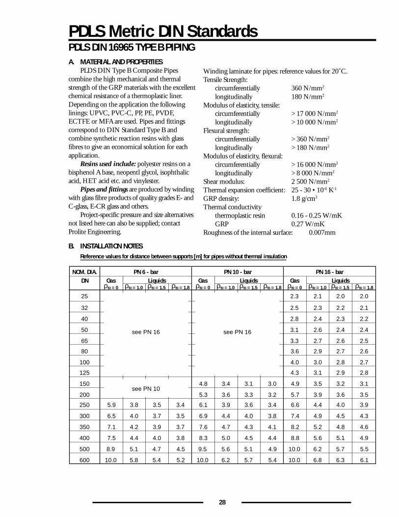
PDLS Metric DIN StandardsPDLS DIN 16965 TYPE B PIPINGA. MATERIAL AND PROPERTIES
PLDS DIN Type B Composite Pipescombine the high mechanical and thermalstrength of the GRP materials with the excellentchemical resistance of a thermoplastic liner.Depending on the application the followinglinings: UPVC, PVC-C, PP, PE, PVDF,ECTFE or MFA are used. Pipes and fittingscorrespond to DIN Standard Type B andcombine synthetic reaction resins with glassfibres to give an economical solution for eachapplication.
Resins used include: polyester resins on abisphenol A base, neopentl glycol, isophthalicacid, HET acid etc. and vinylester.
Pipes and fittings are produced by windingwith glass fibre products of quality grades E- andC-glass, E-CR glass and others.
Project-specific pressure and size alternativesnot listed here can also be supplied; contactProlite Engineering.
NOM. DIA. PN 6 - barGasDN Liquids
25
32
40
50
65
80
100
125
150
200
300 4.0 3.5
250 3.8 3.4
350 4.2 3.7
400
500
600
8.9
10.0
5.1
5.8
4.7
5.4
4.5
5.2
4.4
3.7
3.5
3.9
4.0 3.8
ρfil = 0 ρfil = 1.0 ρfil = 1.5 ρfil = 1.8
6.5
5.9
7.1
7.5
PN 10 - barGas Liquids
3.4 3.0
3.6 3.2
4.4 3.8
3.9 3.4
4.7 4.1
9.5
10.0
5.6
6.2
5.1
5.7
4.9
5.4
5.0
3.1
3.3
4.0
3.6
4.3
4.5 4.4
ρfil = 0 ρfil = 1.0 ρfil = 1.5 ρfil = 1.8
4.8
5.3
6.9
6.1
7.6
8.3
PN 16 - barGas Liquids
2.1 2.0
2.3 2.1
2.4 2.2
2.6 2.4
2.7 2.5
2.9 2.6
3.0 2.7
3.1 2.8
3.5 3.1
3.9 3.5
4.9 4.3
4.4 3.9
5.2 4.6
10.0
10.0
6.2
6.8
5.7
6.3
5.5
6.1
5.6
2.0
2.2
2.3
2.4
2.6
2.7
2.8
2.9
3.2
3.6
4.5
4.0
4.8
5.1 4.9
ρfil = 0 ρfil = 1.0 ρfil = 1.5 ρfil = 1.8
2.3
2.5
2.8
3.1
3.3
3.6
4.0
4.3
4.9
5.7
7.4
6.6
8.2
8.8
see PN 16 see PN 16
see PN 10
Winding laminate for pipes: reference values for 20˚C.Tensile Strength:
circumferentially 360 N/mm2
longitudinally 180 N/mm2
Modulus of elasticity, tensile:circumferentially > 17 000 N/mm2
longitudinally > 10 000 N/mm2
Flexural strength:circumferentially > 360 N/mm2
longitudinally > 180 N/mm2
Modulus of elasticity, flexural:circumferentially > 16 000 N/mm2
longitudinally > 8 000 N/mm2
Shear modulus: 2 500 N/mm2
Thermal expansion coefficient: 25 - 30 • 10-6 K-1
GRP density: 1.8 g/cm3
Thermal conductivitythermoplastic resin 0.16 - 0.25 W/mKGRP 0.27 W/mK
Roughness of the internal surface: 0.007mm
B. INSTALLATION NOTESReference values for distance between supports [m] for pipes without thermal insulation
29
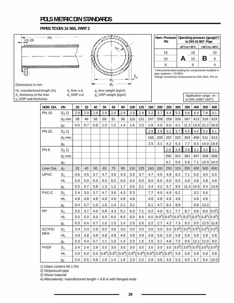
PDLS METRIC DIN STANDARDSPIPES TO DIN 16 965, PART 2
1) Glass content 60 ± 5%2) Stripwound pipe3) Sheet material4) Alternatively: manufactured length = 4.8 m with flanged ends
NOM. DIA. DN
PN 16
PN 10
PN 6
Liner Dia.
UPVC
PVC-C
PP
ECTFE/MFA
PVDF
S4 1)
d3 min.
g4
S4 1)
d3 min.
g4
S4 1)
d3 min.
g4
d2
S1
HL
g1
S1
HL
g1
S1
HL
g1
S1
HL
g1
S1
HL
g1
25
2.9
38
0.5
32
3.6
5.0
0.5
2.4
4.8
0.4
3.5
5.0
0.3
4.8
0.3
2.4
5.0
0.4
32
2.9
46
0.7
40
4.5
5.0
0.7
3.0
4.8
0.7
3.7
5.0
0.4
4.8
0.4
2.4
5.0
0.5
40
2.9
56
0.8
50
3.7
5.0
0.8
3.7
4.8
1.0
4.6
5.0
0.7
4.8
0.7
2.9
5.0
0.8
50
2.9
69
1.0
63
4.7
6.0
1.3
4.7
4.8
1.6
5.8
6.0
1.0
4.8
1.1
3.0
5.84)
1.0
65
2.9
81
1.2
75
3.6
6.0
1.2
3.6
4.8
1.4
4.3
6.0
1.0
4.8
1.0
3.0
5.84)
1.4
80
2.9
96
1.4
90
4.3
6.0
1.7
4.3
4.8
2.1
5.1
6.0
1.4
4.8
1.4
3.0
5.84)
1.5
100
2.9
116
1.6
110
5.3
6.0
2.6
5.3
4.8
3.1
6.3
6.0
2.0
4.8
2.0
3.0
5.84)
2.0
125
2.9
131
2.0
125
3.7
6.0
2.1
7.1
6.0
2.6
4.8
1.5
3.0
5.84)
2.2
150
3.2
167
2.8
160
4.7
6.0
3.4
7.7
4.8
6.1
6.2
6.0
2.2
4.8
2.5
3.0
5.84)
2.9
200
3.7
208
4.0
2.9
206
3.1
200
4.0
6.0
4.2
4.0
4.8
4.7
4.9
6.04)
2.7
5.8
3.1
3.0
5.84)
3.6
250
4.4
259
6.0
3.1
257
4.2
2.9
166
2.5
250
4.9
6.0
5.7
4.9
4.8
6.4
6.1
6.04)
4.2
5.8
4.8
3.0
5.84)
4.5
300
5.3
326
9.1
3.7
322
6.3
2.9
321
5.0
315
6.2
6.0
9.0
6.2
4.8
9.9
7.7
6.04)
7.3
5.8
7.5
3.03)
5.8
5.3
350
5.8
367
11.2
4.0
363
7.7
2.9
361
5.9
2.9
256
4.1
355
7.1
4.8
11.4
8.7
6.04)
9.3
5.8
9.5
3.03)
5.8
6.0
400
6.4
413
13.9
4.4
409
9.5
3.1
407
7.1
400
5.0
4.8
14.5
3.2
4.8
6.8
9.8
6.04)
9.5
5.8
12.1
3.03)
5.8
6.7
500
7.8
516
21.2
5.2
511
14.0
3.6
508
10.3
500
4.0
4.8
9.4
5.6
4.8
14.2
8.0
5.84)
12.5
5.8
12.0
3.03)
5.8
8.4
600
9.1
619
29.6
6.1
613
19.8
4.1
609
14.0
600
5.0
4.8
13.6
5.02)
5.84)
11.6
5.8
9.0
3.03)
2.4 2.4 2.9 3.0 3.0 3.0 3.0 3.0 3.0 3.0 3.0 3.03) 3.03) 3.03) 3.03) 3.03)
5.8
10.0
Application range –A–to DIN 16867 ≤50˚C
Nom. Pressure Operating pressure (gauge)*)PN to DIN 16 867: Pipe
16 16 10
10 10 6
6
*) Recommended loading for components installed inpipe systems = 70-95%Flange connection measurements DIN 2501, PN 10
6 4
-20˚C to +50˚C >50˚C to +80˚C
A B
Dimensions in mm
HL manufactured length (m) d2 liner o.d. g1 liner weight (kg/m)S1 thickness of the liner d3 GRP o.d. g4 GRP weight (kg/m)s4 GRP wall-thickness
30
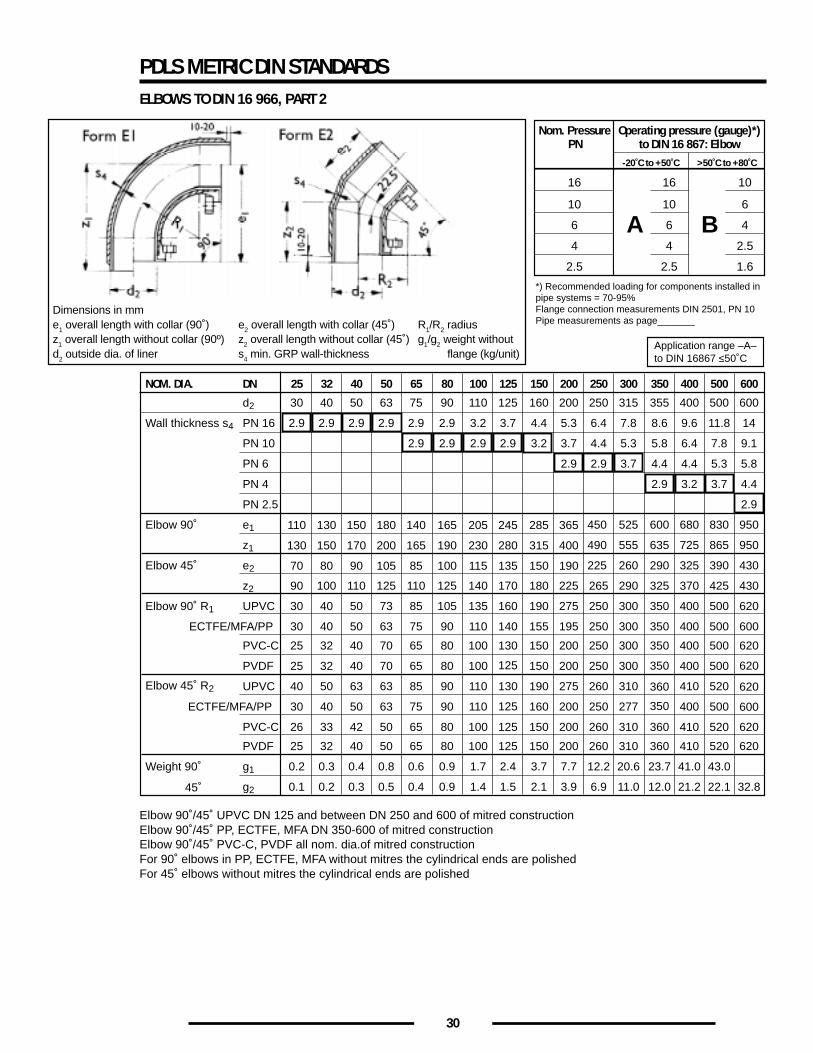
PDLS METRIC DIN STANDARDSELBOWS TO DIN 16 966, PART 2
Elbow 90˚/45˚ UPVC DN 125 and between DN 250 and 600 of mitred constructionElbow 90˚/45˚ PP, ECTFE, MFA DN 350-600 of mitred constructionElbow 90˚/45˚ PVC-C, PVDF all nom. dia.of mitred constructionFor 90˚ elbows in PP, ECTFE, MFA without mitres the cylindrical ends are polishedFor 45˚ elbows without mitres the cylindrical ends are polished
NOM. DIA. DN
Elbow 90˚
Elbow 45˚
Elbow 90˚ R1
Elbow 45˚ R2
Weight 90˚
45˚
d2
PN 16Wall thickness s4
PN 10
PN 6
PN 4
PN 2.5
e1
z1
e2
z2
UPVC
ECTFE/MFA/PP
PVC-C
PVDF
UPVC
ECTFE/MFA/PP
PVC-C
PVDF
g1
g2
25
30
2.9
90
30
30
25
25
40
30
26
25
0.2
0.1
32
40
2.9
100
40
40
32
32
50
40
33
32
0.3
0.2
40
50
2.9
110
50
50
40
40
63
50
42
40
0.4
0.3
50
63
2.9
125
73
63
70
70
63
63
50
50
0.8
0.5
65
75
2.9
2.9
110
85
75
65
65
85
75
65
65
0.6
0.4
80
90
2.9
2.9
125
105
90
80
80
90
90
80
80
0.9
0.9
100
110
3.2
2.9
140
135
110
100
100
110 130
110
100
100
1.7
1.4
125
125
3.7
2.9
170
160
140
130
125
125
125
125
2.4
1.5
150
160
4.4
3.2
180
190
155
150
150
190
160
150
150
3.7
2.1
200
200
5.3
3.7
2.9
225
275
195
110
130
70
130
150
80
150
170
90
180
200
105
140
165
85
165
190
100
205
230
115
245
280
135
285
315
150
365
400
190
200
200
275
200
200
200
7.7
3.9
250
250
6.4
4.4
2.9
265
250
250
250
250
260
250
260
260
12.2
6.9
300
315
7.8
5.3
3.7
525
555
260
290
300
300
300
300
310
277
310
310
20.6
11.0
350
355
8.6
5.8
4.4
2.9
600
635
290
450
490
225
325
350
350
350
350
350
360
360
360
23.7
12.0
400
400
9.6
6.4
4.4
3.2
680
725
325
370
400
400
400
400
410
400
410
410
41.0
21.2
500
500
11.8
7.8
5.3
3.7
830
865
390
425
500
500
500
500
520
500
520
520
43.0
22.1
600
600
14
9.1
5.8
4.4
2.9
950
950
430
430
620
600
620
620
620
600
620
620
32.8
Application range –A–to DIN 16867 ≤50˚C
Nom. Pressure Operating pressure (gauge)*)PN to DIN 16 867: Elbow
16 16 10
10 10 6
6
*) Recommended loading for components installed inpipe systems = 70-95%Flange connection measurements DIN 2501, PN 10Pipe measurements as page_______
6 4
-20˚C to +50˚C >50˚C to +80˚C
4 4 2.5
2.5 2.5 1.6
A B
Dimensions in mme1 overall length with collar (90˚) e2 overall length with collar (45˚) R1/R2 radiusz1 overall length without collar (90º) z2 overall length without collar (45˚) g1/g2 weight withoutd2 outside dia. of liner s4 min. GRP wall-thickness flange (kg/unit)
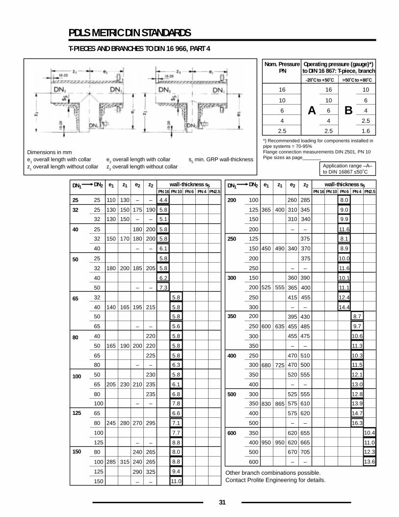
31
PDLS METRIC DIN STANDARDST-PIECES AND BRANCHES TO DIN 16 966, PART 4
Other branch combinations possible.Contact Prolite Engineering for details.
Nom. Pressure Operating pressure (gauge)*)PN to DIN 16 867: T-piece, branch
16 16 10
10 10 6
6
*) Recommended loading for components installed inpipe systems = 70-95%Flange connection measurements DIN 2501, PN 10Pipe sizes as page_______
6 4
-20˚C to +50˚C >50˚C to +80˚C
4 4 2.5
2.5 2.5 1.6
A B
DN1 DN2
25
32
40
50
65
80
100
125
25
25
32
25
32
40
25
32
40
50
32
40
50
65
40
50
65
80
50
65
80
100
65
80
100
125
150 80
100
125
150
e1
110
130
130
140
165
205
245
z1 wall-thickness s5
130
150
150
165
190
230
280
e2
–
175
–
–
195
200
–
210
–
270
z2PN 16 PN 10 PN 6 PN 4 PN2.5
–
190
150 170 180 200
180 200 185 205
180 200
–
– –
–
– –
215
220
220
225
–
230
235
235
–
– –
295
240
290 325
– –
265
285 315 240 265
4.4
5.8
5.1
5.8
5.8
6.1
5.8
5.8
6.2
7.3
5.8
5.8
5.8
5.6
5.8
5.8
5.8
6.3
5.8
6.1
6.8
7.8
6.6
7.1
7.7
8.8
8.0
8.8
9.4
11.0
Application range –A–to DIN 16867 ≤50˚C
DN1 DN2
200
250
300
350
400
500
600
100
125
150
200
125
150
200
250
150
200
250
300
200
250
300
350
250
300
350
400
300
350
400
500
350
400
500
600
e1
260
365
z1 wall-thickness s5
285
400
e2
310
310
365
–
–
470
520
–
z2PN 16 PN 10 PN 6 PN 4 PN2.5
345
450 490
525 555
375
360 390
600 635
395
680 725
470
430
– –
– –
340
340 370
375
400
415 455
455
455
485
–
475
–
510
500
555
–
575
575
–
830 865
525 555
610
620
–
620
670
–
950 950
620 655
665
705
–
8.0
9.0
9.9
11.6
8.1
8.9
10.0
11.6
10.1
11.1
12.4
14.4
8.7
9.7
10.6
11.3
10.3
11.5
12.1
13.0
12.8
13.9
14.7
16.3
10.4
11.0
12.3
13.6
Dimensions in mme1 overall length with collar e2 overall length with collar s5 min. GRP wall-thicknessz1 overall length without collar z2 overall length without collar
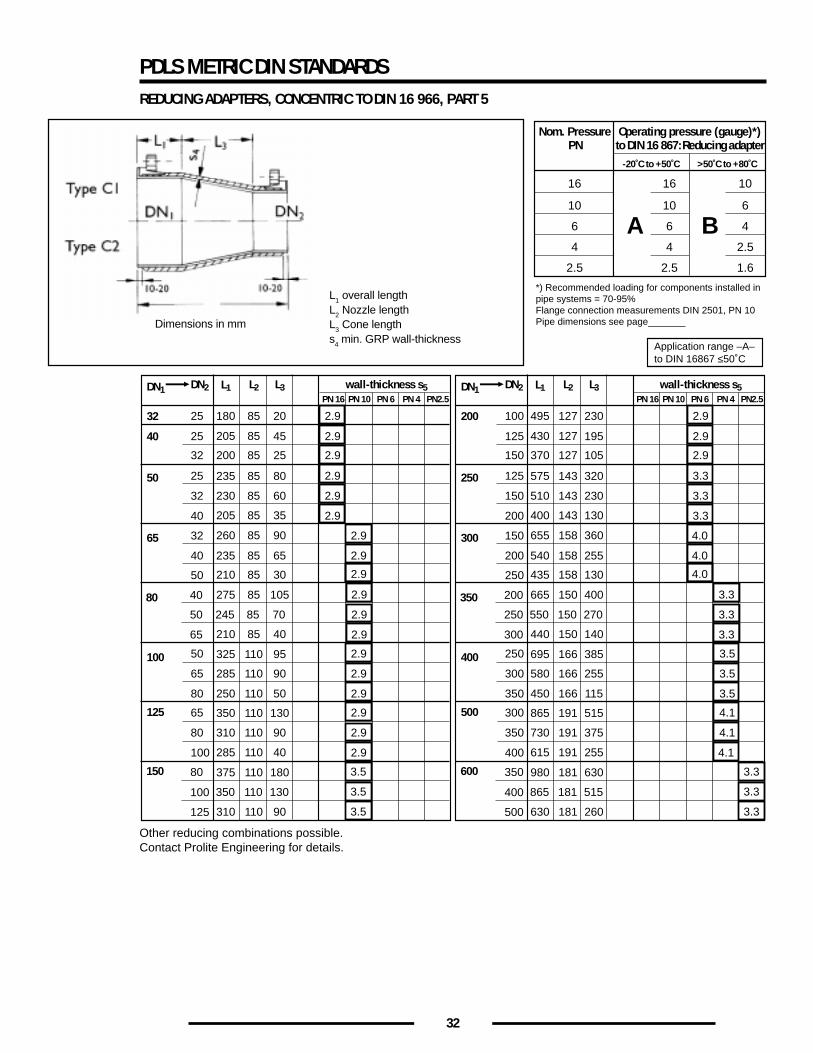
32
PDLS METRIC DIN STANDARDSREDUCING ADAPTERS, CONCENTRIC TO DIN 16 966, PART 5
Other reducing combinations possible.Contact Prolite Engineering for details.
Nom. Pressure Operating pressure (gauge)*)PN to DIN 16 867: Reducing adapter
16 16 10
10 10 6
6
*) Recommended loading for components installed inpipe systems = 70-95%Flange connection measurements DIN 2501, PN 10Pipe dimensions see page_______
6 4
-20˚C to +50˚C >50˚C to +80˚C
4 4 2.5
2.5 2.5 1.6
A B
DN1 DN2
32
40
50
80
100
125
25
25
32
25
32
40
50
40
50
65
50
65
80
65
80
100
150 80
100
125
L1
180
245
285
310
L2 wall-thickness s5
85
205 85
85
110
110
L3
20
70
90
90
PN 16 PN 10 PN 6 PN 4 PN2.5
200 85 25
235 85 80
205 85 35
260 85 90
210 85 30
275 85 105
210 85 40
325 110 95
250 110 50
350 110 130
285 110 40
375 110 180
310 110 90
230 85 60
45
350 110 130
2.9
2.9
2.9
2.9
2.9
2.9
2.9
2.9
2.9
2.9
2.9
2.9
2.9
2.9
2.9
2.9
3.5
3.5
3.5
Application range –A–to DIN 16867 ≤50˚C
65 32
40 235 85 65
2.9
2.9
DN1 DN2
200
250
350
400
500
100
125
150
125
150
200
250
200
250
300
250
300
350
300
350
400
600 350
400
500
L1
495
550
580
730
L2 wall-thickness s5
127
430 127
150
166
191
L3
230
270
255
375
PN 16 PN 10 PN 6 PN 4 PN2.5
370 127 105
575 143 320
400 143 130
655 158 360
435 158 130
665 150 400
440 150 140
695 166 385
450 166 115
865 191 515
615 191 255
980 181 630
630 181 260
510 143 230
195
865 181 515
2.9
2.9
2.9
3.3
3.3
3.3
4.0
3.3
3.3
3.3
3.5
3.5
3.5
4.1
4.1
4.1
3.3
3.3
3.3
300 150
200 540 158 255
4.0
4.0
L1 overall lengthL2 Nozzle lengthL3 Cone lengths4 min. GRP wall-thickness
Dimensions in mm
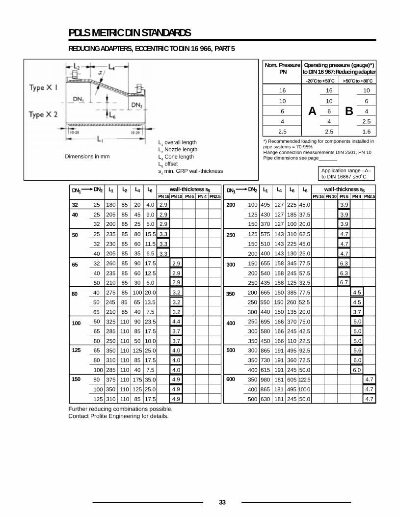
33
PDLS METRIC DIN STANDARDSREDUCING ADAPTERS, ECCENTRIC TO DIN 16 966, PART 5
Further reducing combinations possible.Contact Prolite Engineering for details.
Nom. Pressure Operating pressure (gauge)*)PN to DIN 16 967: Reducing adapter
16 16 10
10 10 6
6
*) Recommended loading for components installed inpipe systems = 70-95%Flange connection measurements DIN 2501, PN 10Pipe dimensions see page_______
6 4
-20˚C to +50˚C >50˚C to +80˚C
4 4 2.5
2.5 2.5 1.6
A B
DN1 DN2
32
40
50
80
100
125
25
25
32
25
32
40
50
40
50
65
50
65
80
65
80
100
150 80
100
125
L1
180
245
285
310
L2 wall-thickness s5
85
205 85
85
110
110
L4 L6
20
65
85
85
PN 16 PN 10 PN 6 PN 4 PN2.5
200 85 25
235 85 80
205 85 35
260 85 90
210 85 30
275 85 100
210 85 40
325 110 90
250 110 50
350 110 125
285 110 40
375 110 175
310 110 85
230 85 60
45
350 110 125
2.9
2.9
2.9
3.3
3.3
3.3
2.9
3.2
3.2
3.2
4.4
3.7
3.7
4.0
4.0
4.0
4.9
4.9
4.9
Application range –A–to DIN 16867 ≤50˚C
65 32
40 235 85 60
4.0
13.5
17.5
17.5
5.0
15.5
6.5
17.5
6.0
20.0
7.5
23.5
10.0
25.0
7.5
35.0
17.5
11.5
9.0
25.0
12.5
2.9
2.9
DN1 DN2
200
250
350
400
500
100
125
150
125
150
200
250
200
250
300
250
300
350
300
350
400
600 350
400
500
L1
495
550
580
730
L4 wall-thickness s5
127
430 127
150
166
191
L6 L6
225
260
245
360
PN 16 PN 10 PN 6 PN 4 PN2.5
370 127 100
575 143 310
400 143 130
655 158 345
435 158 125
665 150 385
440 150 135
695 166 370
450 166 110
865 191 495
615 191 245
980 181 605
630 181 245
510 143 225
185
865 181 495
3.9
3.9
3.9
4.7
4.7
4.7
6.7
4.5
4.5
3.7
5.0
5.0
5.0
5.6
6.0
6.0
4.7
4.7
4.7
300 150
200 540 158 245
45.0
52.5
42.5
72.5
20.0
62.5
25.0
77.5
32.5
77.5
20.0
75.0
22.5
92.5
50.0
122.5
50.0
45.0
37.5
100.0
57.5
6.3
6.3
L1 overall lengthL2 Nozzle lengthL4 Cone lengthL6 offsets4 min. GRP wall-thickness
Dimensions in mm
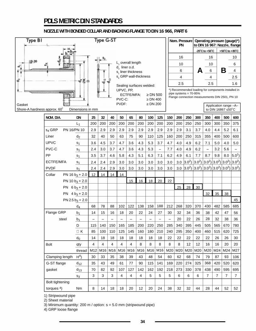
34
PDLS METRIC DIN STANDARDSNOZZLE WITH BONDED COLLAR AND BACKING FLANGE TO DIN 16 966, PART 6
1) Stripwound pipe2) Sheet material3) Minimum quantity: 200 m / option: s = 5.0 mm (stripwound pipe)4) GRP loose flange
Nom. Pressure Operating pressure (gauge)*)PN to DIN 16 967: Nozzle, flange
16 16 10
10 10 6
6
*) Recommended loading for components installed inpipe systems = 70-95%Flange connection measurements DIN 2501, PN 10
6 4
-20˚C to +50˚C >50˚C to +80˚C
4 4 2.5
2.5 2.5 1.6
A B
NOM. DIA. DN
ECTFE/MFA
Collar
Flange GRP
Bolt
L1
PN 16/PN 10s4 GRP
d2
s1
s1
s1
Liner
UPVC
PVC-C
PP
s1
s1PVDF
PN 16 b3 + 2.0
PN 10 b3 + 2.0
PN 6 b3 + 2.0
PN 4 b3 + 2.0
PN 2.5 b3 + 2.0
d4
b1
b1steel
D
∅ K
d0
qty
thread
H4)
d12
d13
s3
25
200
2.9
68
14
–
115
85
14
4
Clamping length
G-ST flange
gasket
Bolt tightening
torques 4) Nm
32
200
2.9
78
15
–
140
100
18
4
40
200
2.9
88
16
–
150
110
18
4
50
200
2.9
102
18
–
165
125
18
4
65
200
2.9
15
122
20
–
185
145
18
4
80
200
2.9
16
138
22
–
200
160
18
8
100
200
2.9
18
158
24 27
–
220
180
18
8
125
200
2.9
20
188
–
250
210
18
8
150
200
2.9
3.6 4.5 3.7 4.7 3.6 4.3 5.3 3.7 4.7
22
212
30
–
285
240
22
8
200
200
2.9
4.0
25
2.4
12
2.4
14
2.9
14
3.0
14
3.0 3.0 3.0 3.0 3.0 3.0
268
32
20
340
295
22
8
250
250
3.1
4.9
28
320
34
22
395
350
22
12
300
250
3.7
6.2
2.4 3.0 3.7 4.7 3.6 4.3 5.3 – 7.7 4.0 4.9 6.2
3.5 3.7 4.6 5.8 4.3 5.1 6.3 7.1 6.2 4.9 6.1 7.7
3.02)
30
370
36
26
445
400
22
12
350
300
4.0
7.1
–
3.02)3.02)
32
430
28
38
505
460
22
16
400
300
4.4
5.0
3.2
3.02)
35
482
42
32
565
515
26
16
500
350
5.2
4.0
5.6
8.7 9.8 8.0
3.02)
38
585
47
38
670
620
26 30
20
600
375
32 40 50 63 75 90 110 125 160 200 250 315 355 400 500 600
6.1
5.0
–
5.01)
3.02)
2.4 2.4 2.9 3.0 3.0 3.0 3.0 3.0 3.0 3.0 3.02) 3.02)3.02) 3.02) 3.02) 3.02)
45
685
56
36
780
725
20
M12
30
35
70
3
8
M16
33
43
82
3
14
M16
35
49
92
3
18
M16
38
61
107
4
18
M16
39
77
127
4
20
M16
43
90
142
4
12
M16
48 54
115
162
5
20
M16
141
192
5
24
M20
60
169
218
5
38
M20
62
220
273
6
32
M20
68
274
330
6
32
M20
74
325
378
6
44
M20
368
79
438
7
28
M24
87
420
490
7
44
M24
93
520
595
7
52
M27
106
620
695
7
52
Application range –A–to DIN 16867 ≤50˚C
L1 overall lengthd2 liner o.d.s1 liner thicknesss4 GRP wall-thickness
Sealing surfaces welded:UPVC, PP, ECTFE/MFA: ≥ DN 500PVC-C: ≥ DN 400PVDF: ≥ DN 200Gasket
Shore-A hardness approx. 60˚ Dimensions in mm
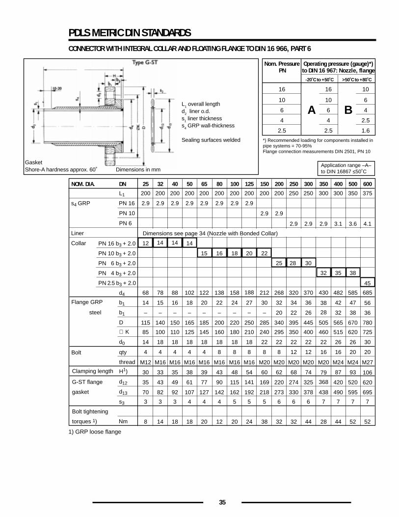
35
PDLS METRIC DIN STANDARDSCONNECTOR WITH INTEGRAL COLLAR AND FLOATING FLANGE TO DIN 16 966, PART 6
1) GRP loose flange
Nom. Pressure Operating pressure (gauge)*)PN to DIN 16 967: Nozzle, flange
16 16 10
10 10 6
6
*) Recommended loading for components installed inpipe systems = 70-95%Flange connection measurements DIN 2501, PN 10
6 4
-20˚C to +50˚C >50˚C to +80˚C
4 4 2.5
2.5 2.5 1.6
A B
NOM. DIA. DN
Flange GRP
Bolt
L1
PN 16s4 GRP
PN 10
PN 6
Liner
Collar PN 16 b3 + 2.0
PN 10 b3 + 2.0
PN 6 b3 + 2.0
PN 4 b3 + 2.0
PN 2.5 b3 + 2.0
d4
b1
b1steel
D
∅ K
d0
qty
thread
H1)
d12
d13
s3
25
200
2.9
68
14
–
115
85
14
4
Clamping length
G-ST flange
gasket
Bolt tightening
torques 1) Nm
32
200
2.9
78
15
–
140
100
18
4
40
200
2.9
88
16
–
150
110
18
4
50
200
2.9
102
18
–
165
125
18
4
65
200
2.9
122
20
–
185
145
18
4
80
200
2.9
138
22
–
200
160
18
8
100
200
2.9
158
24 27
–
220
180
18
8
125
200
2.9
188
–
250
210
18
8
150
200
212
30
–
285
240
22
8
200
200
15 16 18 20 22
25
268
32
20
340
295
22
8
250
250
2.9
320
34
22
395
350
22
12
300
250
2.9
12 14 14 14
30
370
36
26
445
400
22
12
350
300
2.9
32
28
430
28
38
505
460
22
16
400
300
3.1
35
482
42
32
565
515
26
16
500
350
3.6
38
585
47
38
670
620
26 30
20
600
375
2.9 2.9
4.1
45
685
56
36
780
725
20
M12
30
35
70
3
8
M16
33
43
82
3
14
M16
35
49
92
3
18
M16
38
61
107
4
18
M16
39
77
127
4
20
M16
43
90
142
4
12
M16
48 54
115
162
5
20
M16
141
192
5
24
M20
60
169
218
5
38
M20
62
220
273
6
32
M20
68
274
330
6
32
M20
74
325
378
6
44
M20
368
79
438
7
28
M24
87
420
490
7
44
M24
93
520
595
7
52
M27
106
620
695
7
52
Application range –A–to DIN 16867 ≤50˚C
Dimensions see page 34 (Nozzle with Bonded Collar)
L1 overall lengthd2 liner o.d.s1 liner thicknesss4 GRP wall-thickness
Sealing surfaces welded
GasketShore-A hardness approx. 60˚ Dimensions in mm
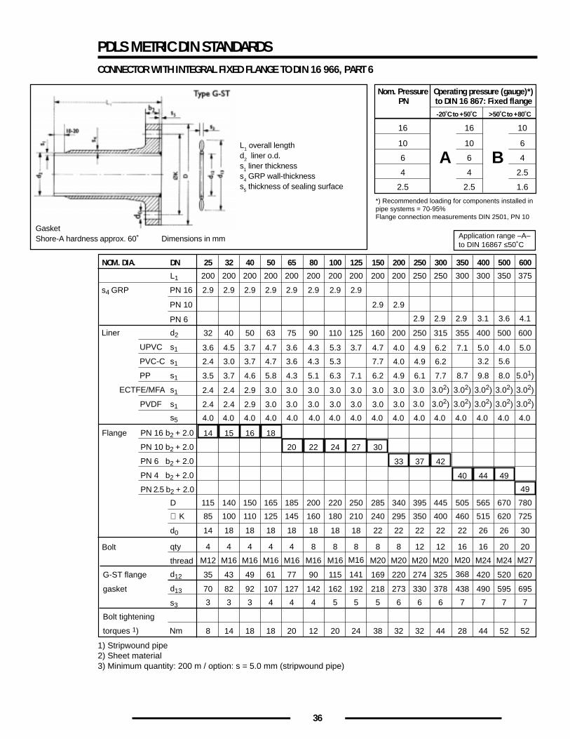
36
1) Stripwound pipe2) Sheet material3) Minimum quantity: 200 m / option: s = 5.0 mm (stripwound pipe)
PDLS METRIC DIN STANDARDSCONNECTOR WITH INTEGRAL FIXED FLANGE TO DIN 16 966, PART 6
Nom. Pressure Operating pressure (gauge)*)PN to DIN 16 867: Fixed flange
16 16 10
10 10 6
6
*) Recommended loading for components installed inpipe systems = 70-95%Flange connection measurements DIN 2501, PN 10
6 4
-20˚C to +50˚C >50˚C to +80˚C
4 4 2.5
2.5 2.5 1.6
A B
NOM. DIA. DN
ECTFE/MFA
Flange
Bolt
L1
PN 16
PN 10
PN 6
s4 GRP
d2
s1
s1
s1
Liner
UPVC
PVC-C
PP
s1
s1
s5
PVDF
PN 16 b2 + 2.0
PN 10 b2 + 2.0
PN 6 b2 + 2.0
PN 4 b2 + 2.0
PN 2.5 b2 + 2.0
D
∅ K
d0
qty
thread
d12
d13
s3
25
200
2.9
115
85
14
4
G-ST flange
gasket
Bolt tightening
torques 1) Nm
32
200
2.9
140
100
18
4
40
200
2.9
150
110
18
4
50
200
2.9
165
125
18
4
65
200
2.9
20
185
145
18
4
80
200
2.9
22
200
160
18
8
100
200
2.9
24
220
180
18
8
125
200
2.9
27
250
210
18
8
150
200
2.9
3.6 4.5 3.7 4.7 3.6 4.3 5.3 3.7 4.7
30
285
240
22
8
200
200
2.9
2.9 2.9 2.9 3.1
4.0
33
2.4
4.0 4.0 4.0 4.0 4.0 4.0 4.0 4.0 4.0 4.0 4.0 4.0 4.0 4.0 4.0 4.0
14
2.4
15
2.9
16
3.0
18
3.0 3.0 3.0 3.0 3.0 3.0
340
295
22
8
250
250
4.9
37
395
350
22
12
300
250
6.2
2.4 3.0 3.7 4.7 3.6 4.3 5.3 7.7 4.0 4.9 6.2
3.5 3.7 4.6 5.8 4.3 5.1 6.3 7.1 6.2 4.9 6.1 7.7
3.02)
42
445
400
22
12
350
300
7.1
3.02)3.0
40
505
460
22
16
400
300
5.0
3.2
3.02)
44
565
515
26
16
500
350
4.0
5.6
8.7 9.8 8.0
3.02)
49
670
620
26 30
20
600
375
32 40 50 63 75 90 110 125 160 200 250 315 355 400 500 600
3.6 4.1
5.0
5.01)
3.02)
2.4 2.4 2.9 3.0 3.0 3.0 3.0 3.0 3.0 3.0 3.02) 3.02)3.0 3.02) 3.02) 3.02)
49
780
725
20
M12
35
70
3
8
M16
43
82
3
14
M16
49
92
3
18
M16
61
107
4
18
M16
77
127
4
20
M16
90
142
4
12
M16
115
162
5
20
M16
141
192
5
24
M20
169
218
5
38
M20
220
273
6
32
M20
274
330
6
32
M20
325
378
6
44
M20
368
438
7
28
M24
420
490
7
44
M24
520
595
7
52
M27
620
695
7
52
Application range –A–to DIN 16867 ≤50˚C
L1 overall lengthd2 liner o.d.s1 liner thicknesss4 GRP wall-thicknesss5 thickness of sealing surface
GasketShore-A hardness approx. 60˚ Dimensions in mm
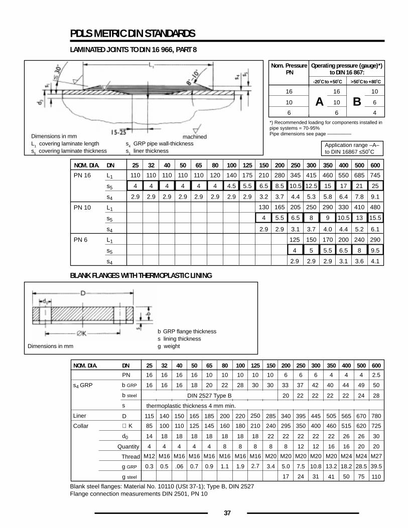
37
Blank steel flanges: Material No. 10110 (USt 37-1); Type B, DIN 2527Flange connection measurements DIN 2501, PN 10
PDLS METRIC DIN STANDARDSLAMINATED JOINTS TO DIN 16 966, PART 8
Nom. Pressure Operating pressure (gauge)*)PN to DIN 16 867:
16 16 10
10 10 6
6
*) Recommended loading for components installed inpipe systems = 70-95%Pipe dimensions see page –––––––––
6 4
-20˚C to +50˚C >50˚C to +80˚C
A B
NOM. DIA. DN
PN 16
PN 10
PN 6
L1
s5
s4
L1
s5
s4
L1
s5
s4
25
110
4
2.9
32
110
4
2.9
40
110
4
2.9
50
110
4
2.9
65
110
4
2.9
80
120
4
2.9
100
140
4.5
2.9
125
175
5.5
2.9
150
210
6.5
3.2
200
280
8.5
3.7
2.9
165
250
345
10.5
4.4
3.1
205
2.9
130
300
415
12.5
5.3
3.7
250
150
5
2.9
350
460
15
5.8
4.0
290
170
5.5
2.9
125
4
2.9
400
550
17
6.4
4.4
330
200
6.5
3.1
500
685
21
7.8
5.2
410
240
8
3.6
600
745
25
9.1
6.1
5.5 6.54 8 9 10.5 13 15.5
480
290
9.5
4.1
Application range –A–to DIN 16867 ≤50˚C
NOM. DIA. DN
PN
b GRPs4 GRP
b steel
g GRP
g steel
s
Liner
Collar
D
∅ K
d0
Quantity
Thread
25
16
16
0.3
14
4
32
16
16
0.5
18
4
40
16
16
.06
18
4
50
16
18
0.7
18
4
65
10
20
0.9
18
4
80
10
22
1.1
18
8
100
10
28
1.9
18
8
125
10
30 30 33 37 42 40 44 49 50
22 22 22 22 24 28
2.7
18
8
150
10
3.4
22
8
200
6
5.0
17
22
8
250
6
7.5
24
22
12
300
6
10.8
31
22
12
350
4
13.2
41
22
16
400
4
18.2
50
26
16
500
4
28.5
75
26 30
20
600
2.5
20
39.5
115 140 150 165 185 200 220 250 285 340 395 445 505 565 670 780
110
85 100 110 125 145 160 180 210 240 295 350 400 460 515 620 725
20
M12 M16 M16 M16 M16 M16 M16 M16 M20 M20 M20 M20 M20 M24 M24 M27
thermoplastic thickness 4 mm min.
DIN 2527 Type B
Dimensions in mmL1 covering laminate length s4 GRP pipe wall-thicknesss5 covering laminate thickness s1 liner thickness
machined
BLANK FLANGES WITH THERMOPLASTIC LINING
Dimensions in mm
b GRP flange thicknesss lining thicknessg weight
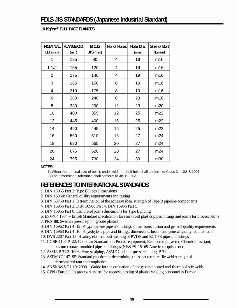
38
PDLS JIS STANDARDS (Japanese Industrial Standard)10 Kg/cm2 FULL FACE FLANGES
NOMINAL FLANGE O.D. B.C.D. No. of Holes Hole Dia. Size of BoltI.D. (inch) (mm) (mm)JIS (mm) Nominal
1 125 90 4 19 m16
1 1/2 155 120 4 19 m16
2 175 140 4 19 m16
3 185 150 8 19 m16
4 210 175 8 19 m16
6 280 240 8 23 m16
8 330 290 12 23 m20
10 400 355 12 25 m22
12 445 400 16 25 m22
14 490 445 16 25 m22
18 620 565 20 27 m24
16 560 510 16 27 m24
20 675 620 20 27 m24
24 795 730 24 33 m30
NOTES:1) When the nominal size of bolt is under m16, the bolt hole shall conform to Class 3 in JIS B 1001.2) The dimensional tolerance shall conform to JIS B 2203.
REFERENCES TO INTERNATIONAL STANDARDS1. DIN 16965 Part 2: Type B Pipes Dimensions2. DIN 16964: General quality requirements and testing3. DIN 53769 Part 1: Determination of the adhesive shear strength of Type B pipeline components4. DIN 16966 Part 2, DIN 16966 Part 4, DIN 16966 Part 55. DIN 16966 Part 8: Laminated joints dimensions for Type B piping6. BS 6464:1984 – British Standard specification for reinforced plastics pipes, fittings and joints for process plants7. PRN 88: Swedish pressure piping code plastics8. DIN 16962 Part 4–12: Polypropylene pipe and fittings, dimensions, fusion and general quality requirements9. DIN 16963 Part 4–10: Polyethylene pipe and fittings, dimensions, fusion and general quality requirements10. DVS 2207 Part 15: Heating element butt welding of PVDF and ECTFE pipe and fittings11. CGSB 41–GP–22: Canadian Standard for: Process equipment; Reinforced polyester; Chemical resistant,
custom contact moulded pipe and fittings (NBS PS–15–69 American equivalent)12. ASME B 31.3–1996: Process piping, ASME Code for pressure piping, B 3113. ASTM C1147–95: Standard practice for determining the short term tensile weld strength of
chemical resistant thermoplastics14. ANSI/AWS G1.10: 2000 – Guide for the evaluation of hot gas and heated tool thermoplastic welds15. CEN (Europe): In process standard for approval testing of plastics welding personnel in Europe.

40


![PROCEEDINGS OF SPIE · 9904 0W The Primordial Inflation Explorer (PIXIE) [9904-26] ... 9904 1K Optical telescope system-level design considerations for a space-based gravitational](https://img.pdfslide.us/doc/110x75/60a531ee7aaa936cd233f439/proceedings-of-spie-9904-0w-the-primordial-inflation-explorer-pixie-9904-26.jpg)