Embed Size (px)
Citation preview
Products Solutions Services
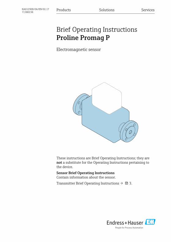
Brief Operating InstructionsProline Promag PElectromagnetic sensor
These instructions are Brief Operating Instructions; they arenot a substitute for the Operating Instructions pertaining tothe device.Sensor Brief Operating InstructionsContain information about the sensor.Transmitter Brief Operating Instructions → 3.
KA01290D/06/EN/02.1771380238
Proline Promag P
2 Endress+Hauser
Order code:
Ext. ord. cd.:
Ser. no.:
www.endress.com/deviceviewer Endress+Hauser
Operations App
XXXXXXXXXXXX
XXXXX-XXXXXX
XXX.XXXX.XX
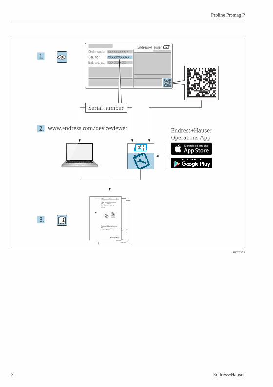
Serial number
1.
3.
2.
A0023555

Proline Promag P Brief Operating Instructions for the device
Endress+Hauser 3
Brief Operating Instructions for the deviceThe device consists of a transmitter and a sensor.The process of commissioning these two components is described in two separate manuals:• Sensor Brief Operating Instructions• Transmitter Brief Operating InstructionsPlease refer to both Brief Operating Instructions when commissioning the device as thecontents of the manuals complement one another:Sensor Brief Operating InstructionsThe Sensor Brief Operating Instructions are aimed at specialists with responsibility forinstalling the measuring device.• Incoming acceptance and product identification• Storage and transport• InstallationTransmitter Brief Operating InstructionsThe Transmitter Brief Operating Instructions are aimed at specialists with responsibility forcommissioning, configuring and parameterizing the measuring device (until the firstmeasured value).• Product description• Installation• Electrical connection• Operation options• System integration• Commissioning• Diagnostic information
Additional device documentationThese Brief Operating Instructions are the Sensor Brief Operating Instructions.The "Transmitter Brief Operating Instructions" are available via:• Internet: www.endress.com/deviceviewer• Smart phone/tablet: Endress+Hauser Operations AppDetailed information about the device can be found in the Operating Instructions and theother documentation:• Internet: www.endress.com/deviceviewer• Smart phone/tablet: Endress+Hauser Operations App
Table of contents Proline Promag P
4 Endress+Hauser
Table of contents1 Document information . . . . . . . . . . . . . . . . . . . . . . . . . . . . . . . . . . . . . . . . . . . . . . . . . . . . . . . . . . . . 51.1 Symbols used . . . . . . . . . . . . . . . . . . . . . . . . . . . . . . . . . . . . . . . . . . . . . . . . . . . . . . . . . . . . . . . . . . . . . . . . . 5
2 Basic safety instructions . . . . . . . . . . . . . . . . . . . . . . . . . . . . . . . . . . . . . . . . . . . . . . . . . . . . . . . . . . 82.1 Requirements for the personnel . . . . . . . . . . . . . . . . . . . . . . . . . . . . . . . . . . . . . . . . . . . . . . . . . . . . . . . . . . . . 82.2 Designated use . . . . . . . . . . . . . . . . . . . . . . . . . . . . . . . . . . . . . . . . . . . . . . . . . . . . . . . . . . . . . . . . . . . . . . . . 82.3 Workplace safety . . . . . . . . . . . . . . . . . . . . . . . . . . . . . . . . . . . . . . . . . . . . . . . . . . . . . . . . . . . . . . . . . . . . . . 92.4 Operational safety . . . . . . . . . . . . . . . . . . . . . . . . . . . . . . . . . . . . . . . . . . . . . . . . . . . . . . . . . . . . . . . . . . . . . . 92.5 Product safety . . . . . . . . . . . . . . . . . . . . . . . . . . . . . . . . . . . . . . . . . . . . . . . . . . . . . . . . . . . . . . . . . . . . . . . . . 92.6 IT security . . . . . . . . . . . . . . . . . . . . . . . . . . . . . . . . . . . . . . . . . . . . . . . . . . . . . . . . . . . . . . . . . . . . . . . . . . . 10
3 Incoming acceptance and product identification . . . . . . . . . . . . . . . . . . . . . . . . . . . . . . . . . 113.1 Incoming acceptance . . . . . . . . . . . . . . . . . . . . . . . . . . . . . . . . . . . . . . . . . . . . . . . . . . . . . . . . . . . . . . . . . . . 113.2 Product identification . . . . . . . . . . . . . . . . . . . . . . . . . . . . . . . . . . . . . . . . . . . . . . . . . . . . . . . . . . . . . . . . . . 12
4 Storage and transport . . . . . . . . . . . . . . . . . . . . . . . . . . . . . . . . . . . . . . . . . . . . . . . . . . . . . . . . . . . 134.1 Storage conditions . . . . . . . . . . . . . . . . . . . . . . . . . . . . . . . . . . . . . . . . . . . . . . . . . . . . . . . . . . . . . . . . . . . . 134.2 Transporting the product . . . . . . . . . . . . . . . . . . . . . . . . . . . . . . . . . . . . . . . . . . . . . . . . . . . . . . . . . . . . . . . . 13
5 Installation . . . . . . . . . . . . . . . . . . . . . . . . . . . . . . . . . . . . . . . . . . . . . . . . . . . . . . . . . . . . . . . . . . . . . . 155.1 Installation conditions . . . . . . . . . . . . . . . . . . . . . . . . . . . . . . . . . . . . . . . . . . . . . . . . . . . . . . . . . . . . . . . . . . 155.2 Mounting the measuring device . . . . . . . . . . . . . . . . . . . . . . . . . . . . . . . . . . . . . . . . . . . . . . . . . . . . . . . . . . . 205.3 Post-installation check . . . . . . . . . . . . . . . . . . . . . . . . . . . . . . . . . . . . . . . . . . . . . . . . . . . . . . . . . . . . . . . . . 23
6 Disposal . . . . . . . . . . . . . . . . . . . . . . . . . . . . . . . . . . . . . . . . . . . . . . . . . . . . . . . . . . . . . . . . . . . . . . . . . 246.1 Removing the measuring device . . . . . . . . . . . . . . . . . . . . . . . . . . . . . . . . . . . . . . . . . . . . . . . . . . . . . . . . . . 246.2 Disposing of the measuring device . . . . . . . . . . . . . . . . . . . . . . . . . . . . . . . . . . . . . . . . . . . . . . . . . . . . . . . . . 24
7 Appendix . . . . . . . . . . . . . . . . . . . . . . . . . . . . . . . . . . . . . . . . . . . . . . . . . . . . . . . . . . . . . . . . . . . . . . . . 247.1 Screw tightening torques . . . . . . . . . . . . . . . . . . . . . . . . . . . . . . . . . . . . . . . . . . . . . . . . . . . . . . . . . . . . . . . . 24
Proline Promag P Document information
Endress+Hauser 5
1 Document information
1.1 Symbols used
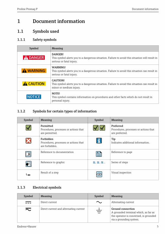
1.1.1 Safety symbols
Symbol Meaning
DANGER
DANGER!This symbol alerts you to a dangerous situation. Failure to avoid this situation will result inserious or fatal injury.
WARNING
WARNING!This symbol alerts you to a dangerous situation. Failure to avoid this situation can result inserious or fatal injury.
CAUTION
CAUTION!This symbol alerts you to a dangerous situation. Failure to avoid this situation can result inminor or medium injury.
NOTICE
NOTE!This symbol contains information on procedures and other facts which do not result inpersonal injury.
1.1.2 Symbols for certain types of information
Symbol Meaning Symbol Meaning
PermittedProcedures, processes or actions thatare permitted.
PreferredProcedures, processes or actions thatare preferred.
ForbiddenProcedures, processes or actions thatare forbidden.
TipIndicates additional information.
Reference to documentation A Reference to page
Reference to graphic 1. , 2. , 3.… Series of steps
Result of a step Visual inspection
1.1.3 Electrical symbols
Symbol Meaning Symbol Meaning
Direct current Alternating current
Direct current and alternating current Ground connectionA grounded terminal which, as far asthe operator is concerned, is groundedvia a grounding system.
Document information Proline Promag P
6 Endress+Hauser
Symbol Meaning
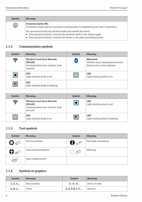
Protective Earth (PE)A terminal which must be connected to ground prior to establishing any other connections.
The ground terminals are situated inside and outside the device:• Inner ground terminal: Connects the protectiv earth to the mains supply.• Outer ground terminal: Connects the device to the plant grounding system.
1.1.4 Communication symbols
Symbol Meaning Symbol Meaning
Wireless Local Area Network(WLAN)Communication via a wireless, localnetwork.
BluetoothWireless data transmission betweendevices over a short distance.
LEDLight emitting diode is off.
LEDLight emitting diode is on.
LEDLight emitting diode is flashing.
Symbol Meaning Symbol Meaning
Wireless Local Area Network(WLAN)Communication via a wireless, localnetwork.
LEDLight emitting diode is off.
LEDLight emitting diode is on.
LEDLight emitting diode is flashing.
1.1.5 Tool symbols
Symbol Meaning Symbol Meaning
Torx screwdriver Flat blade screwdriver
Cross-head screwdriver Allen key
Open-ended wrench
1.1.6 Symbols in graphics
Symbol Meaning Symbol Meaning
1, 2, 3,... Item numbers 1. , 2. , 3.… Series of steps
A, B, C, ... Views A-A, B-B, C-C, ... Sections

Proline Promag P Document information
Endress+Hauser 7
Symbol Meaning Symbol Meaning
-Hazardous area
.Safe area (non-hazardous area)
Flow direction
Basic safety instructions Proline Promag P
8 Endress+Hauser
2 Basic safety instructions
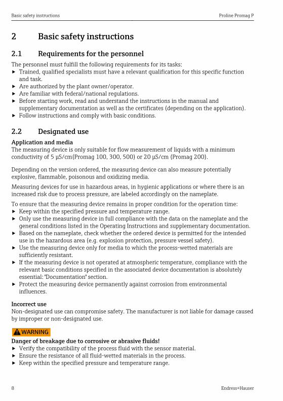
2.1 Requirements for the personnelThe personnel must fulfill the following requirements for its tasks:‣ Trained, qualified specialists must have a relevant qualification for this specific function
and task.‣ Are authorized by the plant owner/operator.‣ Are familiar with federal/national regulations.‣ Before starting work, read and understand the instructions in the manual and
supplementary documentation as well as the certificates (depending on the application).‣ Follow instructions and comply with basic conditions.
2.2 Designated useApplication and mediaThe measuring device is only suitable for flow measurement of liquids with a minimumconductivity of 5 μS/cm(Promag 100, 300, 500) or 20 μS/cm (Promag 200).
Depending on the version ordered, the measuring device can also measure potentiallyexplosive, flammable, poisonous and oxidizing media.Measuring devices for use in hazardous areas, in hygienic applications or where there is anincreased risk due to process pressure, are labeled accordingly on the nameplate.To ensure that the measuring device remains in proper condition for the operation time:‣ Keep within the specified pressure and temperature range.‣ Only use the measuring device in full compliance with the data on the nameplate and the
general conditions listed in the Operating Instructions and supplementary documentation.‣ Based on the nameplate, check whether the ordered device is permitted for the intended
use in the hazardous area (e.g. explosion protection, pressure vessel safety).‣ Use the measuring device only for media to which the process-wetted materials are
sufficiently resistant.‣ If the measuring device is not operated at atmospheric temperature, compliance with the
relevant basic conditions specified in the associated device documentation is absolutelyessential: "Documentation" section.
‣ Protect the measuring device permanently against corrosion from environmentalinfluences.
Incorrect useNon-designated use can compromise safety. The manufacturer is not liable for damage causedby improper or non-designated use.
LWARNINGDanger of breakage due to corrosive or abrasive fluids!‣ Verify the compatibility of the process fluid with the sensor material.‣ Ensure the resistance of all fluid-wetted materials in the process.‣ Keep within the specified pressure and temperature range.
Proline Promag P Basic safety instructions
Endress+Hauser 9
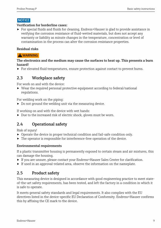
NOTICEVerification for borderline cases:‣ For special fluids and fluids for cleaning, Endress+Hauser is glad to provide assistance in
verifying the corrosion resistance of fluid-wetted materials, but does not accept anywarranty or liability as minute changes in the temperature, concentration or level ofcontamination in the process can alter the corrosion resistance properties.
Residual risks
LWARNINGThe electronics and the medium may cause the surfaces to heat up. This presents a burnhazard!‣ For elevated fluid temperatures, ensure protection against contact to prevent burns.
2.3 Workplace safetyFor work on and with the device:‣ Wear the required personal protective equipment according to federal/national
regulations.
For welding work on the piping:‣ Do not ground the welding unit via the measuring device.
If working on and with the device with wet hands:‣ Due to the increased risk of electric shock, gloves must be worn.
2.4 Operational safetyRisk of injury!‣ Operate the device in proper technical condition and fail-safe condition only.‣ The operator is responsible for interference-free operation of the device.
Environmental requirementsIf a plastic transmitter housing is permanently exposed to certain steam and air mixtures, thiscan damage the housing.‣ If you are unsure, please contact your Endress+Hauser Sales Center for clarification.‣ If used in an approval-related area, observe the information on the nameplate.
2.5 Product safetyThis measuring device is designed in accordance with good engineering practice to meet state-of-the-art safety requirements, has been tested, and left the factory in a condition in which itis safe to operate.It meets general safety standards and legal requirements. It also complies with the EUdirectives listed in the device-specific EU Declaration of Conformity. Endress+Hauser confirmsthis by affixing the CE mark to the device.

Basic safety instructions Proline Promag P
10 Endress+Hauser
2.6 IT securityWe only provide a warranty if the device is installed and used as described in the OperatingInstructions. The device is equipped with security mechanisms to protect it against anyinadvertent changes to the device settings.IT security measures in line with operators' security standards and designed to provideadditional protection for the device and device data transfer must be implemented by theoperators themselves.
Proline Promag P Incoming acceptance and product identification
Endress+Hauser 11
3 Incoming acceptance and product identification
3.1 Incoming acceptance
A0028673
1
2
1
2
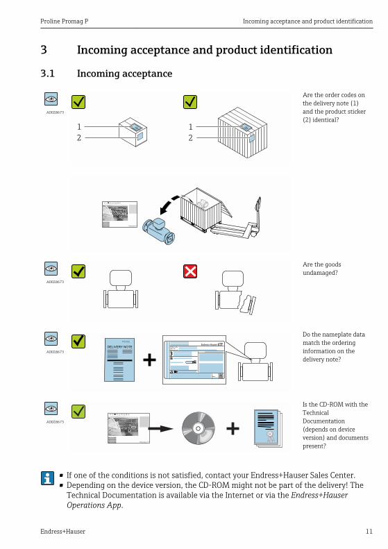
Are the order codes onthe delivery note (1)and the product sticker(2) identical?
A0028673
Are the goodsundamaged?
A0028673Order code:
Ser. no.:
Ext. ord. cd.:
i i
Date:
Do the nameplate datamatch the orderinginformation on thedelivery note?
A0028673
Is the CD-ROM with theTechnicalDocumentation(depends on deviceversion) and documentspresent?
• If one of the conditions is not satisfied, contact your Endress+Hauser Sales Center.• Depending on the device version, the CD-ROM might not be part of the delivery! The
Technical Documentation is available via the Internet or via the Endress+HauserOperations App.
Incoming acceptance and product identification Proline Promag P
12 Endress+Hauser
3.2 Product identificationThe following options are available for identification of the measuring device:• Nameplate specifications• Order code with breakdown of the device features on the delivery note• Enter serial numbers from nameplates in W@M Device Viewer
(www.endress.com/deviceviewer): All information about the measuring device is displayed.• Enter the serial number from the nameplates into the Endress+Hauser Operations App or
scan the 2-D matrix code (QR code) on the nameplate with the Endress+Hauser OperationsApp: all the information for the measuring device is displayed.
Order code:
Ext. ord. cd.:
Ser. no.:
Order code:
Ext. ord. cd.:
Ser. no.:
1
2
3
4
A0030196
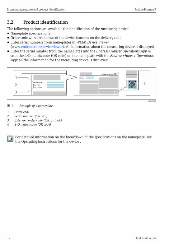
1 Example of a nameplate
1 Order code2 Serial number (Ser. no.)3 Extended order code (Ext. ord. cd.)4 2-D matrix code (QR code)
For detailed information on the breakdown of the specifications on the nameplate, seethe Operating Instructions for the device .
Proline Promag P Storage and transport
Endress+Hauser 13
4 Storage and transport
4.1 Storage conditionsObserve the following notes for storage:‣ Store in the original packaging to ensure protection from shock.‣ Do not remove protective covers or protective caps installed on process connections. They
prevent mechanical damage to the sealing surfaces and contamination in the measuringtube.
‣ Protect from direct sunlight to avoid unacceptably high surface temperatures.‣ Select a storage location where moisture cannot collect in the measuring device as fungus
and bacteria infestation can damage the lining.‣ Store in a dry and dust-free place.‣ Store in a dry place.‣ Do not store outdoors.
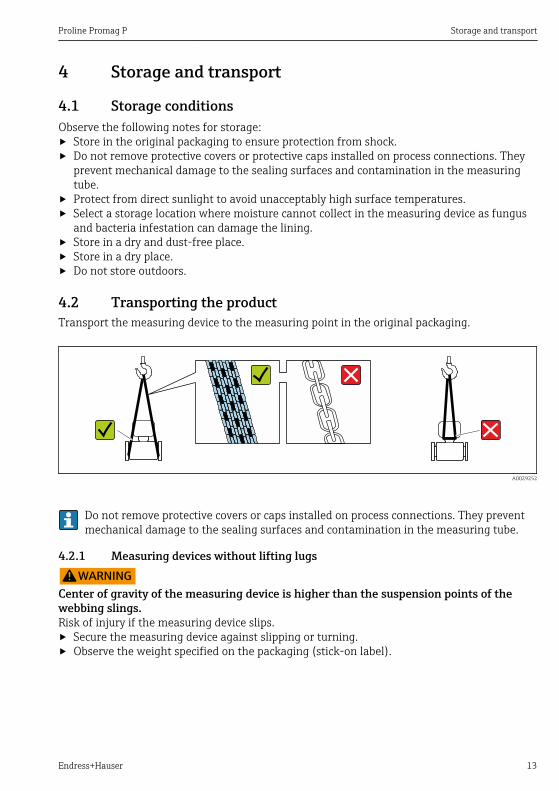
4.2 Transporting the productTransport the measuring device to the measuring point in the original packaging.
A0029252
Do not remove protective covers or caps installed on process connections. They preventmechanical damage to the sealing surfaces and contamination in the measuring tube.
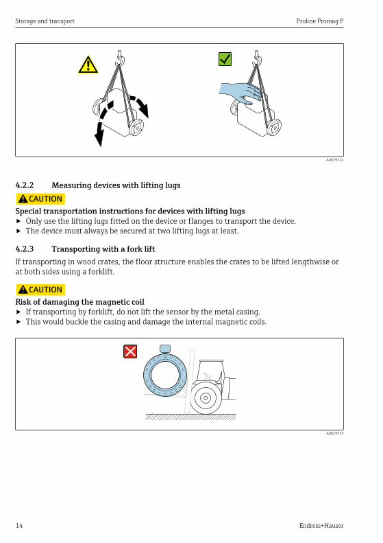
4.2.1 Measuring devices without lifting lugs
LWARNINGCenter of gravity of the measuring device is higher than the suspension points of thewebbing slings.Risk of injury if the measuring device slips.‣ Secure the measuring device against slipping or turning.‣ Observe the weight specified on the packaging (stick-on label).
Storage and transport Proline Promag P
14 Endress+Hauser
A0029214
4.2.2 Measuring devices with lifting lugs
LCAUTIONSpecial transportation instructions for devices with lifting lugs‣ Only use the lifting lugs fitted on the device or flanges to transport the device.‣ The device must always be secured at two lifting lugs at least.
4.2.3 Transporting with a fork liftIf transporting in wood crates, the floor structure enables the crates to be lifted lengthwise orat both sides using a forklift.
LCAUTIONRisk of damaging the magnetic coil‣ If transporting by forklift, do not lift the sensor by the metal casing.‣ This would buckle the casing and damage the internal magnetic coils.
A0029319
Proline Promag P Installation
Endress+Hauser 15
5 Installation
5.1 Installation conditions
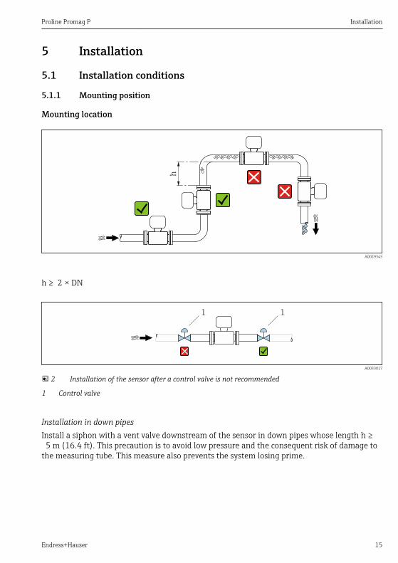
5.1.1 Mounting position
Mounting location
h
A0029343
h ≥ 2 × DN
1 1
A0033017
2 Installation of the sensor after a control valve is not recommended
1 Control valve
Installation in down pipesInstall a siphon with a vent valve downstream of the sensor in down pipes whose length h ≥ 5 m (16.4 ft). This precaution is to avoid low pressure and the consequent risk of damage tothe measuring tube. This measure also prevents the system losing prime.
Installation Proline Promag P
16 Endress+Hauser
h
2
1
A0028981
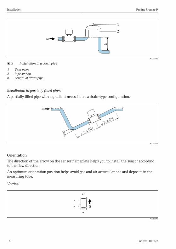
3 Installation in a down pipe
1 Vent valve2 Pipe siphonh Length of down pipe
Installation in partially filled pipesA partially filled pipe with a gradient necessitates a drain-type configuration.
2 x DN
³
5 x DN
³
A0029257
OrientationThe direction of the arrow on the sensor nameplate helps you to install the sensor accordingto the flow direction.An optimum orientation position helps avoid gas and air accumulations and deposits in themeasuring tube.
Vertical
A0015591
Proline Promag P Installation
Endress+Hauser 17
Optimum for self-emptying pipe systems and for use in conjunction with empty pipedetection.
Horizontal• Ideally, the measuring electrode plane should be horizontal. This prevents brief insulation
of the two measuring electrodes by entrained air bubbles.• Empty pipe detection only works if the transmitter housing is pointing upwards as
otherwise there is no guarantee that the empty pipe detection function will actually respondto a partially filled or empty measuring tube.
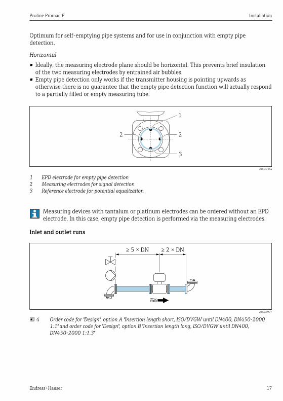
1
2
3
2
A0029344
1 EPD electrode for empty pipe detection2 Measuring electrodes for signal detection3 Reference electrode for potential equalization
Measuring devices with tantalum or platinum electrodes can be ordered without an EPDelectrode. In this case, empty pipe detection is performed via the measuring electrodes.
Inlet and outlet runs
≥ 5 × DN ≥ 2 × DN
A0028997
4 Order code for "Design", option A "Insertion length short, ISO/DVGW until DN400, DN450-20001:1" and order code for "Design", option B "Insertion length long, ISO/DVGW until DN400,DN450-2000 1:1.3"
Installation Proline Promag P
18 Endress+Hauser
≥ 0 × DN
A0032859
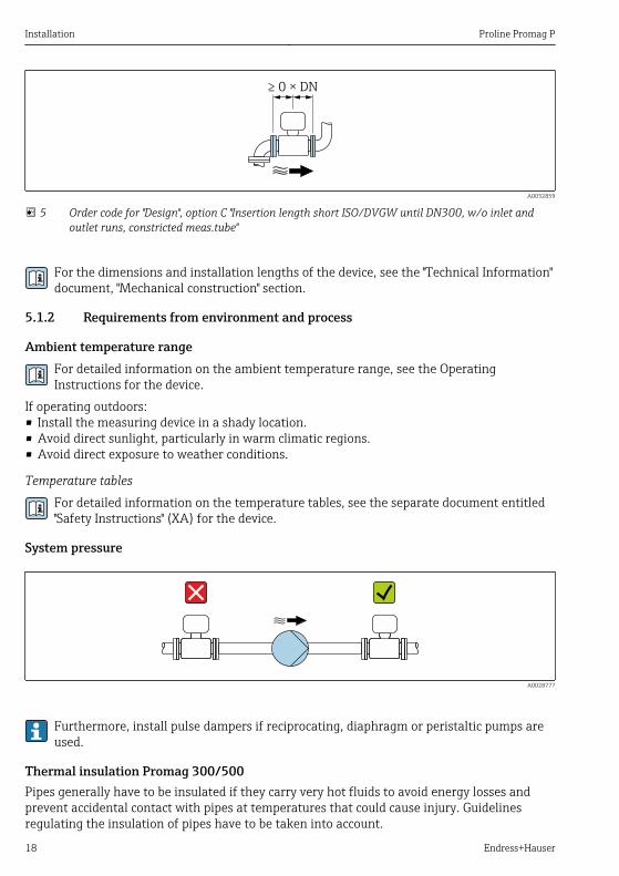
5 Order code for "Design", option C "Insertion length short ISO/DVGW until DN300, w/o inlet andoutlet runs, constricted meas.tube"
For the dimensions and installation lengths of the device, see the "Technical Information"document, "Mechanical construction" section.
5.1.2 Requirements from environment and process
Ambient temperature rangeFor detailed information on the ambient temperature range, see the OperatingInstructions for the device.
If operating outdoors:• Install the measuring device in a shady location.• Avoid direct sunlight, particularly in warm climatic regions.• Avoid direct exposure to weather conditions.
Temperature tablesFor detailed information on the temperature tables, see the separate document entitled"Safety Instructions" (XA) for the device.
System pressure
A0028777
Furthermore, install pulse dampers if reciprocating, diaphragm or peristaltic pumps areused.
Thermal insulation Promag 300/500Pipes generally have to be insulated if they carry very hot fluids to avoid energy losses andprevent accidental contact with pipes at temperatures that could cause injury. Guidelinesregulating the insulation of pipes have to be taken into account.
Proline Promag P Installation
Endress+Hauser 19
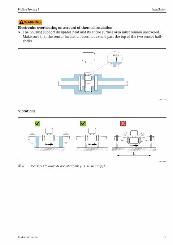
LWARNINGElectronics overheating on account of thermal insulation!‣ The housing support dissipates heat and its entire surface area must remain uncovered.
Make sure that the sensor insulation does not extend past the top of the two sensor half-shells.
max.
A0031216
Vibrations
L
A0029004
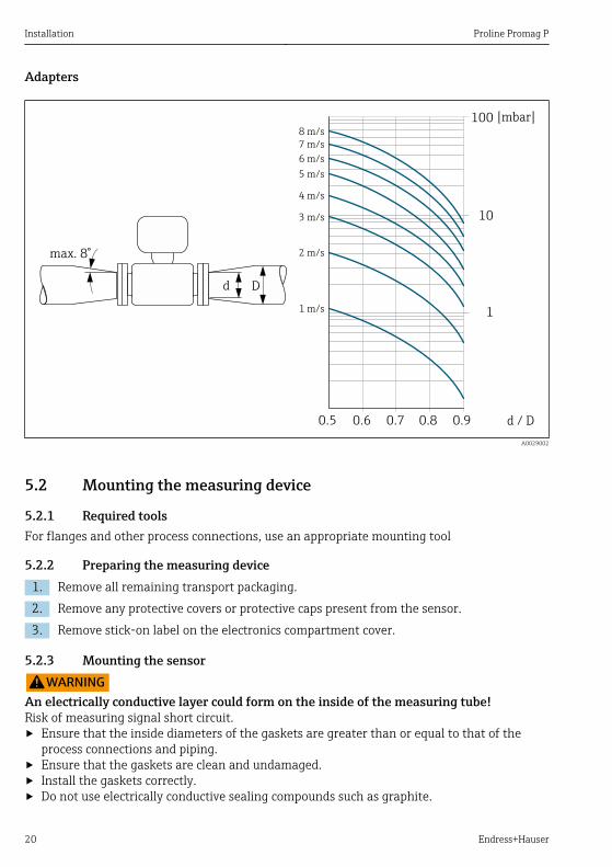
6 Measures to avoid device vibrations (L > 10 m (33 ft))
Installation Proline Promag P
20 Endress+Hauser
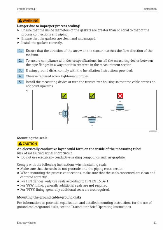
Adapters
100
10
0.5 d / D
[mbar]
0.6 0.7 0.8 0.9
1 m/s
2 m/s
3 m/s
4 m/s
5 m/s
6 m/s
7 m/s
8 m/s
1
Dd
max. 8°
A0029002
5.2 Mounting the measuring device
5.2.1 Required toolsFor flanges and other process connections, use an appropriate mounting tool
5.2.2 Preparing the measuring device1. Remove all remaining transport packaging.2. Remove any protective covers or protective caps present from the sensor.3. Remove stick-on label on the electronics compartment cover.
5.2.3 Mounting the sensor
LWARNINGAn electrically conductive layer could form on the inside of the measuring tube!Risk of measuring signal short circuit.‣ Ensure that the inside diameters of the gaskets are greater than or equal to that of the
process connections and piping.‣ Ensure that the gaskets are clean and undamaged.‣ Install the gaskets correctly.‣ Do not use electrically conductive sealing compounds such as graphite.
Proline Promag P Installation
Endress+Hauser 21
LWARNINGDanger due to improper process sealing!‣ Ensure that the inside diameters of the gaskets are greater than or equal to that of the
process connections and piping.‣ Ensure that the gaskets are clean and undamaged.‣ Install the gaskets correctly.
1. Ensure that the direction of the arrow on the sensor matches the flow direction of themedium.
2. To ensure compliance with device specifications, install the measuring device betweenthe pipe flanges in a way that it is centered in the measurement section.
3. If using ground disks, comply with the Installation Instructions provided.4. Observe required screw tightening torques .5. Install the measuring device or turn the transmitter housing so that the cable entries do
not point upwards.
A0029263
Mounting the seals
LCAUTIONAn electrically conductive layer could form on the inside of the measuring tube!Risk of measuring signal short circuit.‣ Do not use electrically conductive sealing compounds such as graphite.
Comply with the following instructions when installing seals:• Make sure that the seals do not protrude into the piping cross-section.• When mounting the process connections, make sure that the seals concerned are clean and
centered correctly.• For DIN flanges: only use seals according to DIN EN 1514-1.• For "PFA" lining: generally additional seals are not required.• For "PTFE" lining: generally additional seals are not required.
Mounting the ground cable/ground disksFor information on potential equalization and detailed mounting instructions for the use ofground cables/ground disks, see the Transmitter Brief Operating Instructions.

Installation Proline Promag P
22 Endress+Hauser
Screw tightening torques→ 24
Proline Promag P Installation
Endress+Hauser 23
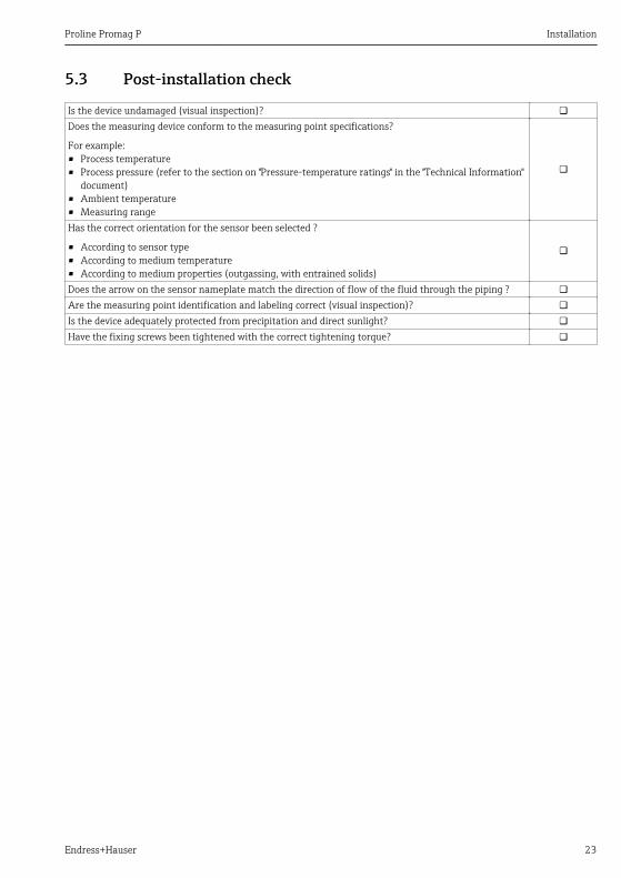
5.3 Post-installation check
Is the device undamaged (visual inspection)? Does the measuring device conform to the measuring point specifications?
For example:• Process temperature• Process pressure (refer to the section on "Pressure-temperature ratings" in the "Technical Information"
document)• Ambient temperature• Measuring range
Has the correct orientation for the sensor been selected ?
• According to sensor type• According to medium temperature• According to medium properties (outgassing, with entrained solids)
Does the arrow on the sensor nameplate match the direction of flow of the fluid through the piping ? Are the measuring point identification and labeling correct (visual inspection)? Is the device adequately protected from precipitation and direct sunlight? Have the fixing screws been tightened with the correct tightening torque?
Disposal Proline Promag P
24 Endress+Hauser
6 Disposal
6.1 Removing the measuring device1. Switch off the device.
LWARNINGDanger to persons from process conditions.‣ Beware of hazardous process conditions such as pressure in the measuring device, high
temperatures or aggressive fluids.
2. Carry out the mounting and connection steps from the "Mounting the measuring device"and "Connecting the measuring device" sections in reverse order. Observe the safetyinstructions.
6.2 Disposing of the measuring deviceLWARNING
Danger to personnel and environment from fluids that are hazardous to health.‣ Ensure that the measuring device and all cavities are free of fluid residues that are
hazardous to health or the environment, e.g. substances that have permeated into crevicesor diffused through plastic.
Observe the following notes during disposal:‣ Observe valid federal/national regulations.‣ Ensure proper separation and reuse of the device components.
7 Appendix
7.1 Screw tightening torquesFor detailed information on the screw tightening torques, see the "Mounting the sensor"section of the Operating Instructions for the device
Please note the following:• The torques listed only apply:
– For lubricated threads.– For pipes that are free from tensile stress.
• Tighten the screws uniformly and in diagonally opposite sequence.• Overtightening the screws will deform the sealing faces or damage the seals.
Proline Promag P Appendix
Endress+Hauser 25
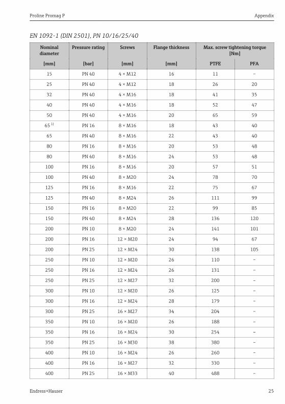
EN 1092-1 (DIN 2501), PN 10/16/25/40
Nominaldiameter
Pressure rating Screws Flange thickness Max. screw tightening torque[Nm]
[mm] [bar] [mm] [mm] PTFE PFA
15 PN 40 4 × M12 16 11 –
25 PN 40 4 × M12 18 26 20
32 PN 40 4 × M16 18 41 35
40 PN 40 4 × M16 18 52 47
50 PN 40 4 × M16 20 65 59
65 1) PN 16 8 × M16 18 43 40
65 PN 40 8 × M16 22 43 40
80 PN 16 8 × M16 20 53 48
80 PN 40 8 × M16 24 53 48
100 PN 16 8 × M16 20 57 51
100 PN 40 8 × M20 24 78 70
125 PN 16 8 × M16 22 75 67
125 PN 40 8 × M24 26 111 99
150 PN 16 8 × M20 22 99 85
150 PN 40 8 × M24 28 136 120
200 PN 10 8 × M20 24 141 101
200 PN 16 12 × M20 24 94 67
200 PN 25 12 × M24 30 138 105
250 PN 10 12 × M20 26 110 –
250 PN 16 12 × M24 26 131 –
250 PN 25 12 × M27 32 200 –
300 PN 10 12 × M20 26 125 –
300 PN 16 12 × M24 28 179 –
300 PN 25 16 × M27 34 204 –
350 PN 10 16 × M20 26 188 –
350 PN 16 16 × M24 30 254 –
350 PN 25 16 × M30 38 380 –
400 PN 10 16 × M24 26 260 –
400 PN 16 16 × M27 32 330 –
400 PN 25 16 × M33 40 488 –
Appendix Proline Promag P
26 Endress+Hauser
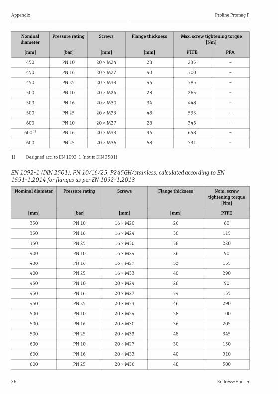
Nominaldiameter
Pressure rating Screws Flange thickness Max. screw tightening torque[Nm]
[mm] [bar] [mm] [mm] PTFE PFA
450 PN 10 20 × M24 28 235 –
450 PN 16 20 × M27 40 300 –
450 PN 25 20 × M33 46 385 –
500 PN 10 20 × M24 28 265 –
500 PN 16 20 × M30 34 448 –
500 PN 25 20 × M33 48 533 –
600 PN 10 20 × M27 28 345 –
600 1) PN 16 20 × M33 36 658 –
600 PN 25 20 × M36 58 731 –
1) Designed acc. to EN 1092-1 (not to DIN 2501)
EN 1092-1 (DIN 2501), PN 10/16/25, P245GH/stainless; calculated according to EN1591-1:2014 for flanges as per EN 1092-1:2013
Nominal diameter Pressure rating Screws Flange thickness Nom. screwtightening torque
[Nm]
[mm] [bar] [mm] [mm] PTFE
350 PN 10 16 × M20 26 60
350 PN 16 16 × M24 30 115
350 PN 25 16 × M30 38 220
400 PN 10 16 × M24 26 90
400 PN 16 16 × M27 32 155
400 PN 25 16 × M33 40 290
450 PN 10 20 × M24 28 90
450 PN 16 20 × M27 34 155
450 PN 25 20 × M33 46 290
500 PN 10 20 × M24 28 100
500 PN 16 20 × M30 36 205
500 PN 25 20 × M33 48 345
600 PN 10 20 × M27 30 150
600 PN 16 20 × M33 40 310
600 PN 25 20 × M36 48 500
Proline Promag P Appendix
Endress+Hauser 27
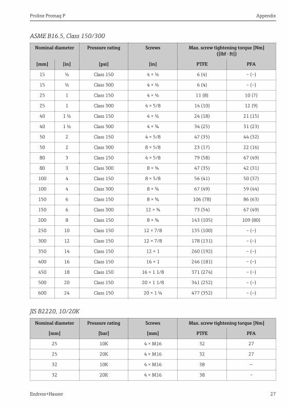
ASME B16.5, Class 150/300
Nominal diameter Pressure rating Screws Max. screw tightening torque [Nm]([lbf · ft])
[mm] [in] [psi] [in] PTFE PFA
15 ½ Class 150 4 × ½ 6 (4) – (–)
15 ½ Class 300 4 × ½ 6 (4) – (–)
25 1 Class 150 4 × ½ 11 (8) 10 (7)
25 1 Class 300 4 × 5/8 14 (10) 12 (9)
40 1 ½ Class 150 4 × ½ 24 (18) 21 (15)
40 1 ½ Class 300 4 × ¾ 34 (25) 31 (23)
50 2 Class 150 4 × 5/8 47 (35) 44 (32)
50 2 Class 300 8 × 5/8 23 (17) 22 (16)
80 3 Class 150 4 × 5/8 79 (58) 67 (49)
80 3 Class 300 8 × ¾ 47 (35) 42 (31)
100 4 Class 150 8 × 5/8 56 (41) 50 (37)
100 4 Class 300 8 × ¾ 67 (49) 59 (44)
150 6 Class 150 8 × ¾ 106 (78) 86 (63)
150 6 Class 300 12 × ¾ 73 (54) 67 (49)
200 8 Class 150 8 × ¾ 143 (105) 109 (80)
250 10 Class 150 12 × 7/8 135 (100) – (–)
300 12 Class 150 12 × 7/8 178 (131) – (–)
350 14 Class 150 12 × 1 260 (192) – (–)
400 16 Class 150 16 × 1 246 (181) – (–)
450 18 Class 150 16 × 1 1/8 371 (274) – (–)
500 20 Class 150 20 × 1 1/8 341 (252) – (–)
600 24 Class 150 20 × 1 ¼ 477 (352) – (–)
JIS B2220, 10/20K
Nominal diameter Pressure rating Screws Max. screw tightening torque [Nm]
[mm] [bar] [mm] PTFE PFA
25 10K 4 × M16 32 27
25 20K 4 × M16 32 27
32 10K 4 × M16 38 –
32 20K 4 × M16 38 –
Appendix Proline Promag P
28 Endress+Hauser
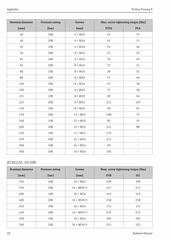
Nominal diameter Pressure rating Screws Max. screw tightening torque [Nm]
[mm] [bar] [mm] PTFE PFA
40 10K 4 × M16 41 37
40 20K 4 × M16 41 37
50 10K 4 × M16 54 46
50 20K 8 × M16 27 23
65 10K 4 × M16 74 63
65 20K 8 × M16 37 31
80 10K 8 × M16 38 32
80 20K 8 × M20 57 46
100 10K 8 × M16 47 38
100 20K 8 × M20 75 58
125 10K 8 × M20 80 66
125 20K 8 × M22 121 103
150 10K 8 × M20 99 81
150 20K 12 × M22 108 72
200 10K 12 × M20 82 54
200 20K 12 × M22 121 88
250 10K 12 × M22 133 –
250 20K 12 × M24 212 –
300 10K 16 × M22 99 –
300 20K 16 × M24 183 –
JIS B2220, 10/20K
Nominal diameter Pressure rating Screws Nom. screw tightening torque [Nm]
[mm] [bar] [mm] PUR HG
350 10K 16 × M22 109 109
350 20K 16 × M30×3 217 217
400 10K 16 × M24 163 163
400 20K 16 × M30×3 258 258
450 10K 16 × M24 155 155
450 20K 16 × M30×3 272 272
500 10K 16 × M24 183 183
500 20K 16 × M30×3 315 315
Proline Promag P Appendix
Endress+Hauser 29
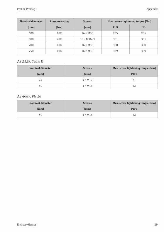
Nominal diameter Pressure rating Screws Nom. screw tightening torque [Nm]
[mm] [bar] [mm] PUR HG
600 10K 16 × M30 235 235
600 20K 16 × M36×3 381 381
700 10K 16 × M30 300 300
750 10K 16 × M30 339 339
AS 2129, Table E
Nominal diameter Screws Max. screw tightening torque [Nm]
[mm] [mm] PTFE
25 4 × M12 21
50 4 × M16 42
AS 4087, PN 16
Nominal diameter Screws Max. screw tightening torque [Nm]
[mm] [mm] PTFE
50 4 × M16 42


www.addresses.endress.com