Embed Size (px)
Citation preview

Products Solutions Services
Description of Device ParametersProline Promag 200HARTElectromagnetic flowmeter
20.50
Display/operat.
Setup
Main menu 0104-1
LanguageEnglish
Español
Français
Language
EnglishDeutsch
Ã
0104-1
Ã
Español
Français
Language
EnglishDeutsch
0104-1
Anzeige/Betrieb
Setup
Hauptmenü
SpracheDeutsch
0104-1
XXXXXXXXX
GP01026D/06/EN/01.1571280342
Valid as of version01.01.zz (Device firmware)


Proline Promag 200 HART Table of contents
Endress+Hauser 3
Table of contents
1 Document information . . . . . . . . . . . . . . 41.1 Document function . . . . . . . . . . . . . . . . . . . . . 41.2 Target group . . . . . . . . . . . . . . . . . . . . . . . . . . 41.3 Using this document . . . . . . . . . . . . . . . . . . . . 4
1.3.1 Information on the documentstructure . . . . . . . . . . . . . . . . . . . . . . . 4
1.3.2 Structure of a parameterdescription . . . . . . . . . . . . . . . . . . . . . 6
1.4 Symbols used . . . . . . . . . . . . . . . . . . . . . . . . . . 61.4.1 Symbols for certain types of
information . . . . . . . . . . . . . . . . . . . . 61.4.2 Symbols in graphics . . . . . . . . . . . . . . . 7
2 Overview of the expert operatingmenu . . . . . . . . . . . . . . . . . . . . . . . . . . . . . . 8
3 Description of device parameters . . . 103.1 "System" submenu . . . . . . . . . . . . . . . . . . . . . 13
3.1.1 "Display" submenu . . . . . . . . . . . . . . . 133.1.2 "Configuration backup display"
submenu . . . . . . . . . . . . . . . . . . . . . . 263.1.3 "Diagnostic handling" submenu . . . . . . 293.1.4 "Administration" submenu . . . . . . . . . 35
3.2 "Sensor" submenu . . . . . . . . . . . . . . . . . . . . . . 403.2.1 "Measured values" submenu . . . . . . . . 403.2.2 "System units" submenu . . . . . . . . . . . 453.2.3 "Process parameters" submenu . . . . . . 533.2.4 "Calculated values" submenu . . . . . . . . 613.2.5 "Sensor adjustment" submenu . . . . . . . 613.2.6 "Calibration" submenu . . . . . . . . . . . . 64
3.3 "Output" submenu . . . . . . . . . . . . . . . . . . . . . . 653.3.1 "Current output 1" submenu . . . . . . . . 663.3.2 "Pulse/frequency/switch output"
submenu . . . . . . . . . . . . . . . . . . . . . . 783.4 "Communication" submenu . . . . . . . . . . . . . . . 89
3.4.1 "HART output" submenu . . . . . . . . . . . 893.4.2 "Diagnostic configuration" submenu . 103
3.5 "Application" submenu . . . . . . . . . . . . . . . . . 1093.5.1 "Totalizer 1 to 3" submenu . . . . . . . . 109
3.6 "Diagnostics" submenu . . . . . . . . . . . . . . . . . 1133.6.1 "Diagnostic list" submenu . . . . . . . . . 1163.6.2 "Event logbook" submenu . . . . . . . . . 1203.6.3 "Device information" submenu . . . . . 1223.6.4 "Data logging" submenu . . . . . . . . . . 1263.6.5 "Min/max values" submenu . . . . . . . 1313.6.6 "Heartbeat" submenu . . . . . . . . . . . . 1353.6.7 "Simulation" submenu . . . . . . . . . . . 136
4 Country-specific factory settings . . 1424.1 SI units . . . . . . . . . . . . . . . . . . . . . . . . . . . . 142
4.1.1 System units . . . . . . . . . . . . . . . . . . 1424.1.2 Full scale values . . . . . . . . . . . . . . . 1424.1.3 Output current span . . . . . . . . . . . . 142
4.1.4 On value low flow cut off . . . . . . . . . 1424.2 US units . . . . . . . . . . . . . . . . . . . . . . . . . . . 143
4.2.1 System units . . . . . . . . . . . . . . . . . . 1434.2.2 Full scale values . . . . . . . . . . . . . . . 1434.2.3 Output current span . . . . . . . . . . . . 1444.2.4 On value low flow cut off . . . . . . . . 144
5 Explanation of abbreviated units . . 1455.1 SI units . . . . . . . . . . . . . . . . . . . . . . . . . . . . 1455.2 US units . . . . . . . . . . . . . . . . . . . . . . . . . . . 1455.3 Imperial units . . . . . . . . . . . . . . . . . . . . . . . 146
Index . . . . . . . . . . . . . . . . . . . . . . . . . . . . . . . . . 147

Document information Proline Promag 200 HART
4 Endress+Hauser
1 Document information
1.1 Document functionThe document is part of the Operating Instructions and serves as a reference forparameters, providing a detailed explanation of each individual parameter of the operatingmenu.
1.2 Target groupThe document is aimed at specialists who work with the device over the entire life cycleand perform specific configurations.
1.3 Using this document
1.3.1 Information on the document structureThis document lists the submenus and their parameters according to the structure of theExpert menu (→ 8).
Expert
System
Sensor
Output
Communication
Application
Diagnostics
Input
Parameter n
Parameter 1
A0022576-EN
1 Sample graphic
For the arrangement of the parameters according to the menu structure of theOperation menu, Setup menu, Diagnostics menu (→ 113), along with shortdescriptions, see the Operating Instructions for the device.

Proline Promag 200 HART Document information
Endress+Hauser 5
Language
Operation
Setup
Wizard 1/Parameter 1
Wizard n/Parameter n
Advanced setup Parameter 1
Submenu 1
Submenu n
Diagnostics Parameter 1
Parameter n
Submenu 1
Submenu n
Parameter n
Language
Parameter 1
Parameter n
Submenu 1
Submenu n
Device tag
A0022577-EN
2 Sample graphic
For information about the operating philosophy, see the "Operating philosophy"chapter in the device's Operating Instructions

Document information Proline Promag 200 HART
6 Endress+Hauser
1.3.2 Structure of a parameter descriptionThe individual parts of a parameter description are described in the following section:
Complete parameter name Write-protected parameter =
Navigation Navigation path to the parameter via the local display (direct access code)Navigation path to the parameter via the operating toolThe names of the menus, submenus and parameters are abbreviated to the form in which they appear onthe display and in the operating tool.
Prerequisite The parameter is only available under these specific conditions
Description Description of the parameter function
Options List of the individual options for the parameter• Option 1• Option 2
User entry Input range for the parameter
User interface User interface value/data for the parameter
Factory setting Default setting ex works
Additional information Additional explanations (e.g. in examples):• On individual options• On display values/data• On the input range• On the factory setting• On the parameter function
1.4 Symbols used
1.4.1 Symbols for certain types of information
Symbol Meaning
TipIndicates additional information.
Reference to documentation
Reference to page
Reference to graphic
Operation via local display
Operation via operating tool
Write-protected parameter

Proline Promag 200 HART Document information
Endress+Hauser 7
1.4.2 Symbols in graphics
Symbol Meaning Symbol Meaning
1, 2, 3 ... Item numbers A, B, C, ... Views
A-A, B-B, C-C, ... Sections

Overview of the expert operating menu Proline Promag 200 HART
8 Endress+Hauser
2 Overview of the expert operating menuThe following table provides an overview of the menu structure of the expert operatingmenu and its parameters. The page reference indicates where the associated description ofthe submenu or parameter can be found.
Expert
Direct access (0106) → 10
Locking status (0004) → 11
Access status display (0091) → 11
Enter access code (0092) → 12
‣ System → 13
‣ Display → 13
‣ Configuration backup display → 26
‣ Diagnostic handling → 29
‣ Administration → 35
‣ Sensor → 40
‣ Measured values → 40
‣ System units → 45
‣ Process parameters → 53
‣ Calculated values → 61
‣ Sensor adjustment → 61
‣ Calibration → 64
‣ Output → 65
‣ Current output 1 → 66
‣ Pulse/frequency/switch output → 78

Proline Promag 200 HART Overview of the expert operating menu
Endress+Hauser 9
‣ Communication → 89
‣ HART output → 89
‣ Diagnostic configuration → 103
‣ Application → 109
Reset all totalizers (2806) → 109
‣ Totalizer 1 to 3 → 109
‣ Diagnostics → 113
Actual diagnostics (0691) → 114
Previous diagnostics (0690) → 115
Operating time from restart (0653) → 116
Operating time (0652) → 116
‣ Diagnostic list → 116
‣ Event logbook → 120
‣ Device information → 122
‣ Data logging → 126
‣ Min/max values → 131
‣ Heartbeat → 135
‣ Simulation → 136
Description of device parameters Proline Promag 200 HART
10 Endress+Hauser
3 Description of device parametersIn the following section, the parameters are listed according to the menu structure of thelocal display. Specific parameters for the operating tools are included at the appropriatepoints in the menu structure.
Expert
Direct access (0106) → 10
Locking status (0004) → 11
Access status display (0091) → 11
Enter access code (0092) → 12
‣ System → 13
‣ Sensor → 40
‣ Output → 65
‣ Communication → 89
‣ Application → 109
‣ Diagnostics → 113
Direct access
Navigation Expert → Direct access (0106)
Description Input of the access code to enable direct access to the desired parameter via the localdisplay. For this reason, each parameter is assigned a parameter number that appears onthe right in the header of the selected parameter in the navigation view.
User entry 0 to 65 535
Additional information User entry
The direct access code consists of a 4-digit number and the channel number, whichidentifies the channel of a process variable: e.g. 0914-1
• The leading zeros in the direct access code do not have to be entered.Example: Input of "914" instead of "0914"
• If no channel number is entered, channel 1 is jumped to automatically.Example: Input of 0914 → Assign process variable parameter
• If a different channel is jumped to: Enter the direct access code with thecorresponding channel number.Example: Input of 0914-3 → Assign process variable parameter

Proline Promag 200 HART Description of device parameters
Endress+Hauser 11
Locking status
Navigation Expert → Locking status (0004)
Description Use this function to view the active write protection.
User interface • Hardware locked• SIL locked• Temporarily locked
Additional information User interface
If two or more types of write protection are active, the write protection with the highestpriority is shown on the local display. In the operating tool all active types of writeprotection are selected.
The -symbol appears in front of parameters that cannot be modified due to writeprotection.
"Hardware locked" option (priority 1)
The DIP switch for hardware locking is activated on the main electronics module. Thislocks write access to the parameters (e.g. via local display or operating tool).
Information on disabling hardware write protection is provided in the "Writeprotection via the locking DIP switch" section of the Operations Instructions for thedevice.
"SIL locked" option (priority 2)
The SIL mode is enabled. This locks write access to the parameters (e.g. via local display oroperating tool).
"Temporarily locked" option (priority 3)
Write access to the parameters is temporarily lock due to device-internal processing (e.g.data upload/download, reset). Once the internal processing has been completed, theparameters can be changed once again.
Access status display
Navigation Expert → Access stat.disp (0091)
Prerequsite A local display is provided.
Description Use this function to view the access authorization to the parameters via the local display.
User interface • Operator• Maintenance
Factory setting Operator

Description of device parameters Proline Promag 200 HART
12 Endress+Hauser
Additional information Description
If the -symbol appears in front of a parameter, it cannot be modified via the local displaywith the current access authorization.
The access authorization can be modified via the Enter access code parameter(→ 12).
For information on the Enter access code parameter (→ 12), see the "Disablingwrite protection via access code" section of the Operating Instructions for the device
If additional write protection is active, this restricts the current access authorizationeven further. The write protection status can be viewed via the Locking statusparameter (→ 11).
User interface
Information on access authorization is provided in the "User roles and associatedaccess authorization" and "Operating concept" sections of the Operations Instructionsfor the device.
Access status tooling
Navigation Expert → Access stat.tool (0005)
Description Use this function to view the access authorization to the parameters via the operating tool.
User interface • Operator• Maintenance
Factory setting Maintenance
Additional information Description
The access authorization can be modified via the Enter access code parameter(→ 12).
If additional write protection is active, this restricts the current access authorizationeven further. The write protection status can be viewed via the Locking statusparameter (→ 11).
User interface
Information on access authorization is provided in the "User roles and associatedaccess authorization" and "Operating concept" sections of the Operations Instructionsfor the device.
Enter access code
Navigation Expert → Ent. access code (0092)
Description Use this function to enter the user-specific release code to remove parameter writeprotection on the local display.
User entry 0 to 9 999

Proline Promag 200 HART Description of device parameters
Endress+Hauser 13
Enter access code
Navigation Expert → Ent. access code (0003)
Description Use this function to enter the user-specific release code to remove parameter writeprotection in the operating tool.
User entry 0 to 9 999
Factory setting 0
3.1 "System" submenu
Navigation Expert → System
‣ System
‣ Display → 13
‣ Configuration backup display → 26
‣ Diagnostic handling → 29
‣ Administration → 35
3.1.1 "Display" submenu
Navigation Expert → System → Display
‣ Display
Language (0104) → 14
Format display (0098) → 15
Value 1 display (0107) → 16
0% bargraph value 1 (0123) → 17
100% bargraph value 1 (0125) → 17
Decimal places 1 (0095) → 18
Value 2 display (0108) → 18

Description of device parameters Proline Promag 200 HART
14 Endress+Hauser
Decimal places 2 (0117) → 19
Value 3 display (0110) → 19
0% bargraph value 3 (0124) → 20
100% bargraph value 3 (0126) → 20
Decimal places 3 (0118) → 20
Value 4 display (0109) → 21
Decimal places 4 (0119) → 21
Display interval (0096) → 22
Display damping (0094) → 22
Header (0097) → 23
Header text (0112) → 23
Separator (0101) → 24
Contrast display (0105) → 24
Backlight (0111) → 25
Access status display (0091) → 25
Language
Navigation Expert → System → Display → Language (0104)
Prerequsite A local display is provided.
Description Use this function to select the configured language on the local display.
Selection • English• Deutsch *
• Français *
• Español *• Italiano *
• Nederlands *
• Portuguesa *
• Polski *
* Visibility depends on order options or device settings

Proline Promag 200 HART Description of device parameters
Endress+Hauser 15
• русский язык (Russian) *
• Svenska *
• Türkçe *
• 中文 (Chinese) *
• 日本語 (Japanese) *
• 한국어 (Korean) *
• * (Arabic) الْعَرَبيّة
• Bahasa Indonesia *
• ภาษาไทย (Thai) *
• tiếng Việt (Vietnamese) *
• čeština (Czech) *
Factory setting English option (alternatively, the ordered language is preset in the device)
Format display
Navigation Expert → System → Display → Format display (0098)
Prerequsite A local display is provided.
Description Use this function to select how the measured value is shown on the local display.
Selection • 1 value, max. size• 1 bargraph + 1 value• 2 values• 1 value large + 2 values• 4 values
Factory setting 1 value, max. size
Additional information Description
The display format (size, bar graph etc.) and number of measured values displayedsimultaneously (1 to 4) can be configured. This setting only applies to normal operation.
• The Value 1 display parameter (→ 16)...Value 4 display parameter(→ 21) parameters are used to specify which measured values are shown onthe display and in which order.
• If more measured values are specified than the display mode selected permits, thenthe values alternate on the device display. The display time until the next change isconfigured using the Display interval parameter (→ 22) parameter.
Possible measured values shown on the local display:
"1 value, max. size" option
X X X X X X XX X
l/h
900.00
A0016529
* Visibility depends on order options or device settings

Description of device parameters Proline Promag 200 HART
16 Endress+Hauser
"1 bargraph + 1 value" option
X X X X X X XX X
60.00
900.00 l/h
%
A0016530
"2 values" option
X X X X X X XX X
l/h
900.00
%
60.00
A0016531
3
"1 value large + 2 values" option
X X X X X X XX X
l/h
900.00
5.98kWh/Nm3
60.00%
A0016532
"4 values" option
X X X X X X XX X
900.00 l/h
60.00 %
5.98 kWh/Nm3
213.94 l
A0016533
Value 1 display
Navigation Expert → System → Display → Value 1 display (0107)
Prerequsite A local display is provided.
Description Use this function to select one of the measured values to be shown on the local display.
Selection • Volume flow• Mass flow• Totalizer 1

Proline Promag 200 HART Description of device parameters
Endress+Hauser 17
• Totalizer 2• Totalizer 3• Current output 1
Factory setting Volume flow
Additional information Description
If several measured values are displayed at once, the measured value selected here will bethe first value to be displayed. The value is only displayed during normal operation.
The Format display parameter (→ 15) is used to specify how many measuredvalues are displayed simultaneously and how.
Selection
The unit of the displayed measured value is taken from the System units submenu(→ 45).
0% bargraph value 1
Navigation Expert → System → Display → 0% bargraph 1 (0123)
Prerequsite A local display is provided.
Description Use this function to enter the 0% bar graph value to be shown on the display for themeasured value 1.
User entry Signed floating-point number
Factory setting 0 l/h
Additional information Description
The Format display parameter (→ 15) is used to specify that the measured valueis to be displayed as a bar graph.
User entry
The unit of the displayed measured value is taken from the System units submenu(→ 45).
100% bargraph value 1
Navigation Expert → System → Display → 100% bargraph 1 (0125)
Prerequsite A local display is provided.
Description Use this function to enter the 100% bar graph value to be shown on the display for themeasured value 1.
User entry Signed floating-point number

Description of device parameters Proline Promag 200 HART
18 Endress+Hauser
Factory setting Depends on country and nominal diameter → 142
Additional information Description
The Format display parameter (→ 15) is used to specify that the measured valueis to be displayed as a bar graph.
User entry
The unit of the displayed measured value is taken from the System units submenu(→ 45).
Decimal places 1
Navigation Expert → System → Display → Decimal places 1 (0095)
Prerequsite A measured value is specified in the Value 1 display parameter (→ 16).
Description Use this function to select the number of decimal places for measured value 1.
Selection • x• x.x• x.xx• x.xxx• x.xxxx
Factory setting x.xx
Additional information Description
This setting does not affect the measuring or computational accuracy of the device.The arrow displayed between the measured value and the unit indicates that thedevice computes with more digits than are shown on the local display.
Value 2 display
Navigation Expert → System → Display → Value 2 display (0108)
Prerequsite A local display is provided.
Description Use this function to select one of the measured values to be shown on the local display.
Selection Picklist see Value 1 display parameter (→ 16)
Factory setting None
Additional information Description
If several measured values are displayed at once, the measured value selected here will bethe second value to be displayed. The value is only displayed during normal operation.
The Format display parameter (→ 15) is used to specify how many measuredvalues are displayed simultaneously and how.

Proline Promag 200 HART Description of device parameters
Endress+Hauser 19
Selection
The unit of the displayed measured value is taken from the System units submenu(→ 45).
Decimal places 2
Navigation Expert → System → Display → Decimal places 2 (0117)
Prerequsite A measured value is specified in the Value 2 display parameter (→ 18).
Description Use this function to select the number of decimal places for measured value 2.
Selection • x• x.x• x.xx• x.xxx• x.xxxx
Factory setting x.xx
Additional information Description
This setting does not affect the measuring or computational accuracy of the device.The arrow displayed between the measured value and the unit indicates that thedevice computes with more digits than are shown on the local display.
Value 3 display
Navigation Expert → System → Display → Value 3 display (0110)
Prerequsite A local display is provided.
Description Use this function to select one of the measured values to be shown on the local display.
Selection Picklist see Value 1 display parameter (→ 16)
Factory setting None
Additional information Description
If several measured values are displayed at once, the measured value selected here will bethe third value to be displayed. The value is only displayed during normal operation.
The Format display parameter (→ 15) is used to specify how many measuredvalues are displayed simultaneously and how.
Selection
The unit of the displayed measured value is taken from the System units submenu(→ 45).

Description of device parameters Proline Promag 200 HART
20 Endress+Hauser
0% bargraph value 3
Navigation Expert → System → Display → 0% bargraph 3 (0124)
Prerequsite An option was selected in the Value 3 display parameter (→ 19).
Description Use this function to enter the 0% bar graph value to be shown on the display for themeasured value 3.
User entry Signed floating-point number
Factory setting 0
Additional information Description
The Format display parameter (→ 15) is used to specify that the measured valueis to be displayed as a bar graph.
User entry
The unit of the displayed measured value is taken from the System units submenu(→ 45).
100% bargraph value 3
Navigation Expert → System → Display → 100% bargraph 3 (0126)
Prerequsite An option was selected in the Value 3 display parameter (→ 19).
Description Use this function to enter the 100% bar graph value to be shown on the display for themeasured value 3.
User entry Signed floating-point number
Factory setting Depends on country and nominal diameter → 142
Additional information Description
The Format display parameter (→ 15) is used to specify that the measured valueis to be displayed as a bar graph.
User entry
The unit of the displayed measured value is taken from the System units submenu(→ 45).
Decimal places 3
Navigation Expert → System → Display → Decimal places 3 (0118)
Prerequsite A measured value is specified in the Value 3 display parameter (→ 19).

Proline Promag 200 HART Description of device parameters
Endress+Hauser 21
Description Use this function to select the number of decimal places for measured value 3.
Selection • x• x.x• x.xx• x.xxx• x.xxxx
Factory setting x.xx
Additional information Description
This setting does not affect the measuring or computational accuracy of the device.The arrow displayed between the measured value and the unit indicates that thedevice computes with more digits than are shown on the local display.
Value 4 display
Navigation Expert → System → Display → Value 4 display (0109)
Prerequsite A local display is provided.
Description Use this function to select one of the measured values to be shown on the local display.
Selection Picklist see Value 1 display parameter (→ 16)
Factory setting None
Additional information Description
If several measured values are displayed at once, the measured value selected here will bethe fourth value to be displayed. The value is only displayed during normal operation.
The Format display parameter (→ 15) is used to specify how many measuredvalues are displayed simultaneously and how.
Selection
The unit of the displayed measured value is taken from the System units submenu(→ 45).
Decimal places 4
Navigation Expert → System → Display → Decimal places 4 (0119)
Prerequsite A measured value is specified in the Value 4 display parameter (→ 21).
Description Use this function to select the number of decimal places for measured value 4.
Description of device parameters Proline Promag 200 HART
22 Endress+Hauser
Selection • x• x.x• x.xx• x.xxx• x.xxxx
Factory setting x.xx
Additional information Description
This setting does not affect the measuring or computational accuracy of the device.The arrow displayed between the measured value and the unit indicates that thedevice computes with more digits than are shown on the local display.
Display interval
Navigation Expert → System → Display → Display interval (0096)
Prerequsite A local display is provided.
Description Use this function to enter the length of time the measured values are displayed if thevalues alternate on the display.
User entry 1 to 10 s
Factory setting 5 s
Additional information Description
This type of alternating display only occurs automatically if the number of measuredvalues defined exceeds the number of values the selected display format can displaysimultaneously.
• The Value 1 display parameter (→ 16)...Value 4 display parameter (→ 21)are used to specify which measured values are shown on the display.
• The display format of the displayed measured values is specified using the Formatdisplay parameter (→ 15).
Display damping
Navigation Expert → System → Display → Display damping (0094)
Prerequsite A local display is provided.
Description Use this function to enter the reaction time of the local display to fluctuations in themeasured value caused by process conditions.
User entry 0.0 to 999.9 s
Factory setting 0.0 s

Proline Promag 200 HART Description of device parameters
Endress+Hauser 23
Additional information User entry
A time constant is entered:• If a low time constant is entered, the display reacts particularly quickly to fluctuating
measured variables.• On the other hand, the display reacts more slowly if a high time constant is entered.
Header
Navigation Expert → System → Display → Header (0097)
Prerequsite A local display is provided.
Description Use this function to select the contents of the header of the local display.
Selection • Device tag• Free text
Factory setting Device tag
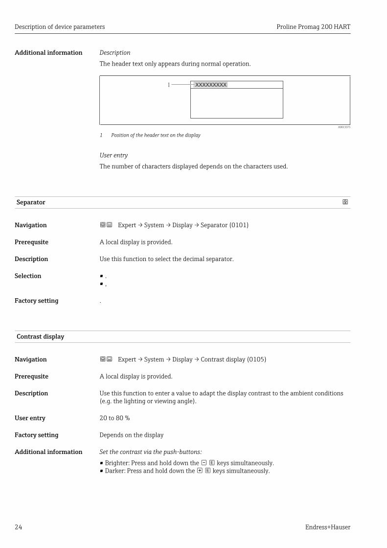
Additional information Description
The header text only appears during normal operation.
1 XXXXXXXXX
A0013375
1 Position of the header text on the display
Selection
• Device tagIs defined in the Device tag parameter (→ 122).
• Free textIs defined in the Header text parameter (→ 23).
Header text
Navigation Expert → System → Display → Header text (0112)
Prerequsite The Free text option is selected in the Header parameter (→ 23).
Description Use this function to enter a customer-specific text for the header of the local display.
User entry Max. 12 characters such as letters, numbers or special characters (e.g. @, %, /)
Factory setting ------------
Description of device parameters Proline Promag 200 HART
24 Endress+Hauser
Additional information Description
The header text only appears during normal operation.
1 XXXXXXXXX
A0013375
1 Position of the header text on the display
User entry
The number of characters displayed depends on the characters used.
Separator
Navigation Expert → System → Display → Separator (0101)
Prerequsite A local display is provided.
Description Use this function to select the decimal separator.
Selection • .• ,
Factory setting .
Contrast display
Navigation Expert → System → Display → Contrast display (0105)
Prerequsite A local display is provided.
Description Use this function to enter a value to adapt the display contrast to the ambient conditions(e.g. the lighting or viewing angle).
User entry 20 to 80 %
Factory setting Depends on the display
Additional information Set the contrast via the push-buttons:
• Brighter: Press and hold down the keys simultaneously.• Darker: Press and hold down the keys simultaneously.

Proline Promag 200 HART Description of device parameters
Endress+Hauser 25
Backlight
Navigation Expert → System → Display → Backlight (0111)
Prerequsite Order code for "Display; operation", option E "SD03 4-line, illum.; touch control + databackup function"
Description Option for switching the backlight of the local display on and off.
Selection • Disable• Enable
Factory setting Disable
Access status display
Navigation Expert → System → Display → Access stat.disp (0091)
Prerequsite A local display is provided.
Description Use this function to view the access authorization to the parameters via the local display.
User interface • Operator• Maintenance
Factory setting Operator
Additional information Description
If the -symbol appears in front of a parameter, it cannot be modified via the local displaywith the current access authorization.
The access authorization can be modified via the Enter access code parameter(→ 12).
For information on the Enter access code parameter (→ 12), see the "Disablingwrite protection via access code" section of the Operating Instructions for the device
If additional write protection is active, this restricts the current access authorizationeven further. The write protection status can be viewed via the Locking statusparameter (→ 11).
User interface
Information on access authorization is provided in the "User roles and associatedaccess authorization" and "Operating concept" sections of the Operations Instructionsfor the device.

Description of device parameters Proline Promag 200 HART
26 Endress+Hauser
3.1.2 "Configuration backup display" submenu
Navigation Expert → System → Conf.backup disp
‣ Configuration backup display
Operating time (0652) → 26
Last backup (0102) → 26
Configuration management (0100) → 26
Comparison result (0103) → 28
Operating time
Navigation Expert → System → Conf.backup disp → Operating time (0652)
Description Use this function to display the length of time the device has been in operation.
User interface Days (d), hours (h), minutes (m) and seconds (s)
Additional information User interface
The maximum number of days is 9999, which is equivalent to 27 years.
Last backup
Navigation Expert → System → Conf.backup disp → Last backup (0102)
Prerequsite A local display is provided.
Description Use this function to display the time since a backup copy of the data was last saved to thedisplay module.
User interface Days (d), hours (h), minutes (m) and seconds (s)
Configuration management
Navigation Expert → System → Conf.backup disp → Config. managem. (0100)
Prerequsite A local display is provided.
Description Use this function to select an action to save the data to the display module.

Proline Promag 200 HART Description of device parameters
Endress+Hauser 27
Selection • Cancel• Execute backup• Restore• Duplicate• Compare• Clear backup data
Factory setting Cancel
Additional information Description
Configuration via the local display is disabled while the action is performed.
For information on the status message in the operating tool, see the Backup stateparameter (→ 27)
Selection
• CancelNo action is executed and the user exits the parameter.
• Execute backup– A backup copy of the current device configuration in the HistoROM is saved to the
display module of the device. The backup copy includes the transmitter data of thedevice.
– The following message appears on local display: Backup active, please wait!• Restore
– The last backup copy of the device configuration is copied from the display module tothe HistoROM of the device. The backup copy comprises the transmitter data of thedevice.
– The following message appears on local display: Restore active! Do not interrupt powersupply!
• Duplicate– The transmitter configuration from another device is duplicated to the device using the
display module.– The following message appears on local display: Copy active! Do not interrupt power
supply!• Compare
– The device configuration saved in the display module is compared to the current deviceconfiguration of the HistoROM.
– The following message appears on local display: Comparing files– The result can be viewed in the Comparison result parameter (→ 28).
• Clear backup data– The backup copy of the device configuration is deleted from the display module of the
device.– The following message appears on local display: Deleting file
HistoROM
A HistoROM is a "non-volatile" device memory in the form of an EEPROM.
Backup state
Navigation Expert → System → Conf.backup disp → Backup state (0121)
Prerequsite A local display is provided.
Description Use this function to view the status of the data backup process.

Description of device parameters Proline Promag 200 HART
28 Endress+Hauser
User interface • None• Store in progress• Restore in progress• Import in progress• Delete in progress• Compare in progress
Factory setting None
Comparison result
Navigation Expert → System → Conf.backup disp → Compar. result (0103)
Prerequsite A local display is provided.
Description Use this function to view the last result of comparing the current device configuration tothe backup copy in the display module.
User interface • Settings identical• Settings not identical• No backup available• Backup settings corrupt• Check not done• Dataset incompatible
Factory setting Check not done
Additional information Description
The comparison is started via the Compare option in the Configurationmanagement parameter (→ 26).
Selection
• Settings identical– The current device configuration of the HistoROM is identical to the backup copy in the
display module.– If the transmitter configuration of another device has been copied to the device via the
display module and the Duplicate option in the Configuration managementparameter (→ 26), the current device configuration of the HistoROM only partlymatches the backup copy in the display module: The settings for the transmitter arenot identical.
• Settings not identicalThe current device configuration of the HistoROM is not identical to the backup copy inthe display module.
• No backup availableThere is no backup copy of the device configuration of the HistoROM in the displaymodule.
• Backup settings corruptThe current device configuration of the HistoROM is corrupt or not compatible with thebackup copy in the display module.
• Check not doneThe device configuration of the HistoROM has not yet been compared to the backup copyin the display module.
• Dataset incompatibleThe backup copy in the display module is not compatible with the device.

Proline Promag 200 HART Description of device parameters
Endress+Hauser 29
HistoROM
A HistoROM is a "non-volatile" device memory in the form of an EEPROM.
3.1.3 "Diagnostic handling" submenu
Navigation Expert → System → Diagn. handling
‣ Diagnostic handling
Alarm delay (0651) → 29
‣ Diagnostic behavior → 30
Alarm delay
Navigation Expert → System → Diagn. handling → Alarm delay (0651)
Description Use this function to enter the time interval until the device generates a diagnosticmessage.
User entry 0 to 60 s
Factory setting 0 s
Additional information Description
This setting affects the following diagnostic messages:• 832 Electronic temperature too high• 833 Electronic temperature too low

Description of device parameters Proline Promag 200 HART
30 Endress+Hauser
"Diagnostic behavior" submenuFor a list of all the diagnostic events, see the Operating Instructions for the device.
Modifying the diagnostic behavior of a diagnostic event. Each diagnostic event isassigned a certain diagnostic behavior at the factory. The user can change thisassignment for certain diagnostics events.
The following options are available in the Assign behavior of diagnostic no. xxxparameters:• Off option
The diagnostic event is ignored; it is neither entered into the Event logbook, nor is adiagnostic message generated.
• Alarm optionThe device continues to measure. The signal outputs assume the defined alarmcondition. A diagnostic message is generated.
• Warning optionThe device continues to measure. A diagnostic message is generated.
• Logbook entry only optionThe device continues to measure. The diagnostic message is entered in the Eventlogbook submenu (→ 120) (Event list submenu (→ 121)) only and is notdisplayed in alternation with the measured value display.
Navigation Expert → System → Diagn. handling → Diagn. behavior
‣ Diagnostic behavior
Assign behavior of diagnostic no. 004(0734)
→ 31
Assign behavior of diagnostic no. 441(0657)
→ 31
Assign behavior of diagnostic no. 442(0658)
→ 31
Assign behavior of diagnostic no. 443(0659)
→ 32
Assign behavior of diagnostic no. 531(0733)
→ 32
Assign behavior of diagnostic no. 801(0660)
→ 33
Assign behavior of diagnostic no. 832(0675)
→ 33
Assign behavior of diagnostic no. 833(0676)
→ 33
Assign behavior of diagnostic no. 861(0736)
→ 34

Proline Promag 200 HART Description of device parameters
Endress+Hauser 31
Assign behavior of diagnostic no. 862(0679)
→ 34
Assign behavior of diagnostic no. 937(0735)
→ 34
Assign behavior of diagnostic no. 004 (Sensor)
Navigation Expert → System → Diagn. handling → Diagn. behavior → Diagnostic no. 004 (0734)
Description Use this function to change the diagnostic behavior of the diagnostic message 004 Sensor.
Selection • Off• Alarm• Warning• Logbook entry only
Factory setting Warning
Additional information For a detailed description of the options available for selection: → 30
Assign behavior of diagnostic no. 441 (Current output 1)
Navigation Expert → System → Diagn. handling → Diagn. behavior → Diagnostic no. 441 (0657)
Description Use this function to change the diagnostic behavior of the diagnostic message441 Current output 1.
Selection • Off• Alarm• Warning• Logbook entry only
Factory setting Warning
Additional information For a detailed description of the options available for selection: → 30
Assign behavior of diagnostic no. 442 (Frequency output)
Navigation Expert → System → Diagn. handling → Diagn. behavior → Diagnostic no. 442 (0658)
Prerequsite The measuring device has a pulse/frequency/switch output.

Description of device parameters Proline Promag 200 HART
32 Endress+Hauser
Description Use this function to change the diagnostic behavior of the diagnostic message442 Frequency output.
Selection • Off• Alarm• Warning• Logbook entry only
Factory setting Warning
Additional information For a detailed description of the options available for selection: → 30
Assign behavior of diagnostic no. 443 (Pulse output)
Navigation Expert → System → Diagn. handling → Diagn. behavior → Diagnostic no. 443 (0659)
Prerequsite The measuring device has a pulse/frequency/switch output.
Description Use this function to change the diagnostic behavior of the diagnostic message 443 Pulseoutput.
Selection • Off• Alarm• Warning• Logbook entry only
Factory setting Warning
Additional information For a detailed description of the options available for selection: → 30
Assign behavior of diagnostic no. 531 (Empty pipe detection)
Navigation Expert → System → Diagn. handling → Diagn. behavior → Diagnostic no. 531 (0733)
Description Use this function to change the diagnostic behavior of the diagnostic message 531 Emptypipe detection.
Selection • Off• Alarm• Warning• Logbook entry only
Factory setting Warning
Additional information For a detailed description of the options available for selection: → 30
Proline Promag 200 HART Description of device parameters
Endress+Hauser 33
Assign behavior of diagnostic no. 801 (Supply voltage too low)
Navigation Expert → System → Diagn. handling → Diagn. behavior → Diagnostic no. 801 (0660)
Description Use this function to change the diagnostic behavior of the diagnostic message 801 Supplyvoltage too low.
Selection • Off• Alarm• Warning• Logbook entry only
Factory setting Warning
Additional information For a detailed description of the options available for selection: → 30
Assign behavior of diagnostic no. 832 (Electronic temperature too high)
Navigation Expert → System → Diagn. handling → Diagn. behavior → Diagnostic no. 832 (0675)
Description Use this function to change the diagnostic behavior of the diagnostic message832 Electronic temperature too high.
Selection • Off• Alarm• Warning• Logbook entry only
Factory setting Warning
Additional information For a detailed description of the options available for selection: → 30
Assign behavior of diagnostic no. 833 (Electronic temperature too low)
Navigation Expert → System → Diagn. handling → Diagn. behavior → Diagnostic no. 833 (0676)
Description Use this function to change the diagnostic behavior of the diagnostic message833 Electronic temperature too low.
Selection • Off• Alarm• Warning• Logbook entry only
Factory setting Warning
Additional information For a detailed description of the options available for selection: → 30

Description of device parameters Proline Promag 200 HART
34 Endress+Hauser
Assign behavior of diagnostic no. 861 (Process fluid)
Navigation Expert → System → Diagn. handling → Diagn. behavior → Diagnostic no. 861 (0736)
Description Use this function to change the diagnostic behavior of the diagnostic message 861 Processfluid.
Selection • Off• Alarm• Warning• Logbook entry only
Factory setting Alarm
Additional information For a detailed description of the options available for selection: → 30
Assign behavior of diagnostic no. 862 (Empty pipe)
Navigation Expert → System → Diagn. handling → Diagn. behavior → Diagnostic no. 862 (0679)
Description Use this function to change the diagnostic behavior of the diagnostic message 862 Emptypipe.
Selection • Off• Alarm• Warning• Logbook entry only
Factory setting Warning
Additional information For a detailed description of the options available for selection: → 30
Assign behavior of diagnostic no. 937 (EMC interference)
Navigation Expert → System → Diagn. handling → Diagn. behavior → Diagnostic no. 937 (0735)
Description Use this function to change the diagnostic behavior of the diagnostic message 937 EMCinterference.
Selection • Off• Alarm• Warning• Logbook entry only
Factory setting Warning

Proline Promag 200 HART Description of device parameters
Endress+Hauser 35
Additional information For a detailed description of the options available for selection: → 30
3.1.4 "Administration" submenu
Navigation Expert → System → Administration
‣ Administration
‣ Define access code → 35
Device reset (0000) → 37
Activate SW option (0029) → 38
Software option overview (0015) → 38
Activate sensor emergency mode(6611)
→ 38
Reset write protection (0019) → 39
"Define access code" wizardThe Define access code wizard is only available if you are operating via the localdisplay. If you are operating via the operating tool, the Define access code parameter(→ 36) is directly in the Administration submenu. The Confirm access codeparameter is not available if you are operating via the operating tool.
Navigation Expert → System → Administration → Def. access code
‣ Define access code
Define access code → 35
Confirm access code → 36
Define access code
Navigation Expert → System → Administration → Def. access code → Def. access code
Description Use this function to enter a user-specific release code to restrict write-access to theparameters. This protects the configuration of the device against any inadvertent changesvia the local display.
User entry 0 to 9 999

Description of device parameters Proline Promag 200 HART
36 Endress+Hauser
Factory setting 0
Additional information Description
The write protection affects all parameters in the document marked with the symbol.On the local display, the symbol in front of a parameter indicates that the parameter iswrite-protected.
Once the access code has been defined, write-protected parameters can only bemodified if the access code is entered in the Enter access code parameter (→ 12).
Please contact your Endress+Hauser Sales Center if you lose your access code.
User entry
A message is displayed if the access code is not in the input range.
Factory setting
If the factory setting is not changed or 0 is defined as the access code, the parameters arenot write-protected and the device configuration data can be modified. The user is loggedon in the "Maintenance" role.
Confirm access code
Navigation Expert → System → Administration → Def. access code → Confirm code
Description Enter the defined release code a second time to confirm the release code.
User entry 0 to 9 999
Factory setting 0
Additional parameters in the "Administration" submenu
Define access code
Navigation Expert → System → Administration → Def. access code (0093)
Description Use this function to enter a user-specific release code to restrict write-access to theparameters. This protects the configuration of the device against any inadvertent changesvia the operating tool.
User entry 0 to 9 999
Factory setting 0

Proline Promag 200 HART Description of device parameters
Endress+Hauser 37
Additional information Description
The write protection affects all parameters in the document marked with the symbol.
Once the access code has been defined, write-protected parameters can only bemodified if the access code is entered in the Enter access code parameter (→ 12).
Please contact your Endress+Hauser Sales Center if you lose your access code.
User entry
A message is displayed if the access code is not in the input range.
Factory setting
If the factory setting is not changed or 0 is defined as the access code, the parameters arenot write-protected and the device configuration data can be modified. The user is loggedon in the "Maintenance" role.
Device reset
Navigation Expert → System → Administration → Device reset (0000)
Description Use this function to choose whether to reset the device configuration - either entirely or inpart - to a defined state.
Selection • Cancel• To factory defaults• To delivery settings• Restart device
Factory setting Cancel
Additional information "Cancel" option
No action is executed and the user exits the parameter.
"To factory defaults" option
Every parameter is reset to its factory setting.
"To delivery settings" option
Every parameter for which a customer-specific default setting was ordered is reset to thiscustomer-specific value. All other parameters are reset to the factory setting.
This option is not visible if no customer-specific settings have been ordered.
"Restart device" option
The restart resets every parameter whose data are in the volatile memory (RAM) to thefactory setting (e.g. measured value data). The device configuration remains unchanged.

Description of device parameters Proline Promag 200 HART
38 Endress+Hauser
Activate SW option
Navigation Expert → System → Administration → Activate SW opt. (0029)
Description Use this function to enter an activation code to enable an additional, ordered softwareoption.
User entry Positive integer
Factory setting 0
Additional information User entry
Endress+Hauser provides the corresponding activation code for the software optionwith the order.
Example
Order code for "Application package", option EA "Extended HistoROM"
Software option overview
Navigation Expert → System → Administration → SW option overv. (0015)
Description Use this function to display all the software options that are enabled in the device.
User interface • Extended HistoROM• SIL• Heartbeat Verification
Additional information Description
Displays all the options that are available if ordered by the customer.
"Extended HistoROM" option
Order code for "Application Package", option EA "Extended HistoROM"
"SIL" option
Order code for "Additional Approval", option LA "SIL"
"Heartbeat Verification" option
Order code for "Application Package", option EB "Heartbeat Verification"
Activate sensor emergency mode
Navigation Expert → System → Administration → Sens. emerg.mode (6611)
Prerequsite The device has identified an error during verification of the characteristics in the sensordata storage or electronics module. A diagnostic message of status type F is output.

Proline Promag 200 HART Description of device parameters
Endress+Hauser 39
Description Use this function to switch on the emergency mode of the sensor to use the backup of thesensor characteristics or main electronics characteristics stored in the HistoROM.
Selection • Cancel• Ok
Factory setting Cancel
Additional information Description
The status signal of the output diagnostic message changes from F (failure) to M(maintenance required), the diagnostic behavior changes from Alarm to Warning: M.The diagnostic message is output until the characteristics in the sensor data storage areagain correct.
Information on what is causing the diagnostic message, and remedy measures, can beviewed by pressing the -button.
Information on status signals and diagnostic behavior: Operating Instructions aboutthe device, "Diagnostic message" chapter
Reset write protection
Navigation Expert → System → Administration → Res. write prot. (0019)
Prerequsite The SIL mode has been enabled.
Description Use this function to enter the SIL locking code to disable write protection in the SIL mode.
User entry 0 to 65 535
Factory setting 0
Additional information Prerequisite
For detailed information about enabling and disabling the SIL mode, see the SpecialDocumentation for the device
Description
Once the SIL mode has been activated, the process-related parameters are writeprotected, and thereby locked, for security reasons. It is still possible to read theparameters. When SIL locking is enabled, restrictions apply on all communicationoptions, such as the service interface, the HART protocol and the onsite display.

Description of device parameters Proline Promag 200 HART
40 Endress+Hauser
3.2 "Sensor" submenu
Navigation Expert → Sensor
‣ Sensor
‣ Measured values → 40
‣ System units → 45
‣ Process parameters → 53
‣ Calculated values → 61
‣ Sensor adjustment → 61
‣ Calibration → 64
3.2.1 "Measured values" submenu
Navigation Expert → Sensor → Measured val.
‣ Measured values
‣ Process variables → 40
‣ Totalizer → 41
‣ Output values → 43
"Process variables" submenu
Navigation Expert → Sensor → Measured val. → Process variab.
‣ Process variables
Volume flow (1838) → 40
Mass flow (1847) → 41
Volume flow
Navigation Expert → Sensor → Measured val. → Process variab. → Volume flow (1838)
Description Use this function to view the volume flow currently measured.

Proline Promag 200 HART Description of device parameters
Endress+Hauser 41
User interface Signed floating-point number
Additional information Dependency
The unit is taken from the Volume flow unit parameter (→ 46)
Mass flow
Navigation Expert → Sensor → Measured val. → Process variab. → Mass flow (1847)
Description Use this function to view the mass flow currently calculated.
User interface Signed floating-point number
Additional information Dependency
The unit is taken from the Mass flow unit parameter (→ 47)
Totalizer
Navigation Expert → Sensor → Measured val. → Totalizer → Totalizer val. 1to 3 (0911–1 to 3)
‣ Totalizer
Totalizer value 1 to 3 (0911–1 to 3) → 41
Totalizer overflow 1 to 3 (0910–1 to 3) → 42
Totalizer value 1 to 3
Navigation Expert → Sensor → Measured val. → Totalizer → Totalizer val. 1 to 3 (0911–1 to 3)
Prerequsite In the Assign process variable parameter (→ 110) in the Totalizer 1 to 3 submenu,one of the following options is selected:• Volume flow• Mass flow
Description Use this function to check the current totalizer reading.
User interface Signed floating-point number
Factory setting 0 l

Description of device parameters Proline Promag 200 HART
42 Endress+Hauser
Additional information Description
As it is only possible to display a maximum of 7 digits, the current counter value is the sumof the totalizer value and the overflow value from the Totalizer overflow 1 to 3parameterif the display range is exceeded.
In the event of an error, the totalizer adopts the mode defined in the Failure modeparameter (→ 113).
User interface
The value of the process variable totalized since measuring began can be positive ornegative. This depends on the settings in the Totalizer operation mode parameter(→ 111).
The unit of the selected process variable is specified for the totalizer in the Unittotalizer parameter (→ 110).
Example
Calculation of the current totalizer reading when the value exceeds the 7-digit displayrange:• Value in the Totalizer value 1 parameter: 196 845.7 m3
• Value in the Totalizer overflow 1 parameter: 1 107 (1 overflow) = 10 000 000 [m3]• Current totalizer reading:10 196 845.7 m3
Totalizer overflow 1 to 3
Navigation Expert → Sensor → Measured val. → Totalizer → Tot. overflow 1 to 3 (0910–1 to 3)
Prerequsite In the Assign process variable parameter (→ 110) in the Totalizer 1 to 3 submenu,one of the following options is selected:• Volume flow• Mass flow
Description Use this function to display the current totalizer overflow.
User interface Integer with sign
Factory setting 0
Additional information Description
If the current reading has more than 7 digits, which is the maximum value range that canbe displayed, the value above this range is given as an overflow. The current totalizer valueis therefore the sum of the overflow value and the totalizer value from the Totalizer value1 to 3 parameter
User interface
The unit of the selected process variable is specified for the totalizer in the Unittotalizer parameter (→ 110).

Proline Promag 200 HART Description of device parameters
Endress+Hauser 43
Example
Calculation of the current totalizer reading when the value exceeds the 7-digit displayrange:• Value in the Totalizer value 1 parameter: 196 845.7 m3
• Value in the Totalizer overflow 1 parameter: 2 107 (2 overflows) = 20 000 000 [m3]• Current totalizer reading: 20 196 845.7 m3
"Output values" submenu
Navigation Expert → Sensor → Measured val. → Output values
‣ Output values
Output current 1 (0361–1) → 43
Measured current 1 (0366–1) → 43
Terminal voltage 1 (0662) → 44
Pulse output (0456) → 44
Output frequency (0471) → 45
Switch status (0461) → 45
Output current 1
Navigation Expert → Sensor → Measured val. → Output values → Output curr. 1 (0361–1)
Description Use this function to view the actual calculated value of the output current.
User interface 3.59 to 22.5 mA
Measured current 1
Navigation Expert → Sensor → Measured val. → Output values → Measur. curr. 1 (0366–1)
Description Use this function to display the actual measured value of the output current.
User interface 0 to 30 mA

Description of device parameters Proline Promag 200 HART
44 Endress+Hauser
Terminal voltage 1
Navigation Expert → Sensor → Measured val. → Output values → Terminal volt. 1 (0662)
Description Use this function to view the actual terminal voltage that is present at the current output.
User interface 0.0 to 50.0 V
Pulse output
Navigation Expert → Sensor → Measured val. → Output values → Pulse output (0456)
Prerequsite The Pulse option is selected in the Operating mode parameter (→ 79).
Description Use this function to display the pulse frequency currently output.
User interface Positive floating-point number
Additional information Description
The pulse output is an open collector output. This is configured at the factory so that thetransistor is conductive for the duration of the pulse (NO contact).
With the Value per pulse parameter (→ 80) and Pulse width parameter (→ 80)it is possible to define the value - i.e. the measured value amount that is equivalent to apulse, and the duration of the pulse.
1
0
1
0
NC
NO
A0025816-EN
0 Non-conductive1 ConductiveNC Normally closedNO Normally opened
The output behavior can be inverted via the Invert output signal parameter (→ 89),i.e. the transistor is not conductive for the duration of the pulse.
In addition, the behavior of the output in the event of an error (Failure mode parameter(→ 81)) can be configured.

Proline Promag 200 HART Description of device parameters
Endress+Hauser 45
Output frequency
Navigation Expert → Sensor → Measured val. → Output values → Output freq. (0471)
Prerequsite The Frequency option is selected in the Operating mode parameter (→ 79).
Description Use this function to view the actual value of the output frequency which is currentlymeasured.
User interface 0 to 1 250 Hz
Switch status
Navigation Expert → Sensor → Measured val. → Output values → Switch status (0461)
Prerequsite The Switch option is selected in the Operating mode parameter (→ 79).
Description Use this function to view the current switch status of the status output.
User interface • Open• Closed
3.2.2 "System units" submenu
Navigation Expert → Sensor → System units
‣ System units
Volume flow unit (0553) → 46
Volume unit (0563) → 47
Mass flow unit (0554) → 47
Mass unit (0574) → 48
Density unit (0555) → 49
Temperature unit (0557) → 49
Date/time format (2812) → 50
‣ User-specific units → 50

Description of device parameters Proline Promag 200 HART
46 Endress+Hauser
Volume flow unit
Navigation Expert → Sensor → System units → Volume flow unit (0553)
Description Use this function to select the unit for the volume flow.
Selection SI units• cm³/s• cm³/min• cm³/h• cm³/d• dm³/s• dm³/min• dm³/h• dm³/d• m³/s• m³/min• m³/h• m³/d• ml/s• ml/min• ml/h• ml/d• l/s• l/min• l/h• l/d• hl/s• hl/min• hl/h• hl/d• Ml/s• Ml/min• Ml/h• Ml/d
US units• af/s• af/min• af/h• af/d• ft³/s• ft³/min• ft³/h• ft³/d• fl oz/s (us)• fl oz/min (us)• fl oz/h (us)• fl oz/d (us)• gal/s (us)• gal/min (us)• gal/h (us)• gal/d (us)• kgal/s (us)• kgal/min (us)• kgal/h (us)• kgal/d (us)• Mgal/s (us)• Mgal/min (us)• Mgal/h (us)• Mgal/d (us)• bbl/s (us;liq.)• bbl/min (us;liq.)• bbl/h (us;liq.)• bbl/d (us;liq.)• bbl/s (us;beer)• bbl/min (us;beer)• bbl/h (us;beer)• bbl/d (us;beer)• bbl/s (us;oil)• bbl/min (us;oil)• bbl/h (us;oil)• bbl/d (us;oil)• bbl/s (us;tank)• bbl/min (us;tank)• bbl/h (us;tank)• bbl/d (us;tank)
Imperial units• gal/s (imp)• gal/min (imp)• gal/h (imp)• gal/d (imp)• Mgal/s (imp)• Mgal/min (imp)• Mgal/h (imp)• Mgal/d (imp)• bbl/s (imp;beer)• bbl/min (imp;beer)• bbl/h (imp;beer)• bbl/d (imp;beer)• bbl/s (imp;oil)• bbl/min (imp;oil)• bbl/h (imp;oil)• bbl/d (imp;oil)
Custom-specific units• User vol./s• User vol./min• User vol./h• User vol./d
Factory setting Country-specific:• l/h• gal/min (us)

Proline Promag 200 HART Description of device parameters
Endress+Hauser 47
Additional information Result
The selected unit applies for:Volume flow (→ 40)
Selection
For an explanation of the abbreviated units: → 145
Customer-specific units
The unit for the customer-specific volume is specified in the User volume textparameter (→ 51).
Volume unit
Navigation Expert → Sensor → System units → Volume unit (0563)
Description Use this function to select the unit for the volume.
Selection SI units• cm³• dm³• m³• ml• l• hl• Ml Mega
US units• af• ft³• fl oz (us)• gal (us)• kgal (us)• Mgal (us)• bbl (us;oil)• bbl (us;liq.)• bbl (us;beer)• bbl (us;tank)
Imperial units• gal (imp)• Mgal (imp)• bbl (imp;beer)• bbl (imp;oil)
Custom-specific unitsUser vol.
Factory setting Country-specific:• m³• gal (us)
Additional information Selection
For an explanation of the abbreviated units: → 145
Customer-specific units
The unit for the customer-specific volume is specified in the User volume textparameter (→ 51).
Mass flow unit
Navigation Expert → Sensor → System units → Mass flow unit (0554)
Description Use this function to select the unit for the mass flow.

Description of device parameters Proline Promag 200 HART
48 Endress+Hauser
Selection SI units• g/s• g/min• g/h• g/d• kg/s• kg/min• kg/h• kg/d• t/s• t/min• t/h• t/d
US units• oz/s• oz/min• oz/h• oz/d• lb/s• lb/min• lb/h• lb/d• STon/s• STon/min• STon/h• STon/d
Custom-specific units• User mass/s• User mass/min• User mass/h• User mass/d
Factory setting Country-specific:• kg/h• lb/min
Additional information Result
The selected unit applies for:Mass flow (→ 41)
Selection
For an explanation of the abbreviated units: → 145
Customer-specific units
The unit for the customer-specific mass is specified in the User mass text parameter(→ 52).
Mass unit
Navigation Expert → Sensor → System units → Mass unit (0574)
Description Use this function to select the unit for the mass.
Selection SI units• g• kg• t
US units• oz• lb• STon
Custom-specific unitsUser mass
Factory setting Country-specific:• kg• lb

Proline Promag 200 HART Description of device parameters
Endress+Hauser 49
Additional information Selection
For an explanation of the abbreviated units: → 145
Customer-specific units
The unit for the customer-specific mass is specified in the User mass text parameter(→ 52).
Density unit
Navigation Expert → Sensor → System units → Density unit (0555)
Description Use this function to select the unit for the density.
Selection SI units• g/cm³• g/m³• kg/dm³• kg/l• kg/m³• SD4°C• SD15°C• SD20°C• SG4°C• SG15°C• SG20°C
US units• lb/ft³• lb/gal (us)• lb/bbl (us;liq.)• lb/bbl (us;beer)• lb/bbl (us;oil)• lb/bbl (us;tank)
Imperial units• lb/gal (imp)• lb/bbl (imp;beer)• lb/bbl (imp;oil)
Factory setting Country-specific:• kg/l• lb/ft³
Additional information Result
The selected unit applies for:Fixed density (→ 61)
Selection
• SD = specific densityThe specific density is the ratio of the density of the fluid to the density of water at awater temperature of +4 °C (+39 °F), +15 °C (+59 °F), +20 °C (+68 °F).
• SG = specific gravity
For an explanation of the abbreviated units: → 145
Temperature unit
Navigation Expert → Sensor → System units → Temperature unit (0557)
Description Use this function to select the unit for the temperature.

Description of device parameters Proline Promag 200 HART
50 Endress+Hauser
Selection SI units• °C• K
US units• °F• °R
Factory setting Country-specific:• °C• °F
Additional information Result
The selected unit applies for:• Maximum value (→ 134)• Minimum value (→ 133)• Maximum value (→ 135)• Minimum value (→ 134)• Average value (→ 135)
Selection
For an explanation of the abbreviated units: → 145
Date/time format
Navigation Expert → Sensor → System units → Date/time format (2812)
Description Use this function to select the desired time format for calibration history.
Selection • dd.mm.yy hh:mm• dd.mm.yy hh:mm am/pm• mm/dd/yy hh:mm• mm/dd/yy hh:mm am/pm
Factory setting dd.mm.yy hh:mm
Additional information Selection
For an explanation of the abbreviated units: → 145
"User-specific units" submenu
Navigation Expert → Sensor → System units → User-spec. units
‣ User-specific units
User volume text (0567) → 51
User volume offset (0569) → 51

Proline Promag 200 HART Description of device parameters
Endress+Hauser 51
User volume factor (0568) → 52
User mass text (0560) → 52
User mass offset (0562) → 52
User mass factor (0561) → 53
User volume text
Navigation Expert → Sensor → System units → User-spec. units → Volume text (0567)
Description Use this function to enter a text for the user-specific unit of volume and volume flow. Thecorresponding time units (s, min, h, d) for volume flow are generated automatically.
User entry Max. 10 characters such as letters, numbers or special characters (@, %, /)
Factory setting User vol.
Additional information Result
The defined unit is shown as an option in the choose list of the following parameters:• Volume flow unit parameter (→ 46)• Volume unit parameter (→ 47)
Example
If the text GLAS is entered, the choose list of the Volume flow unit parameter (→ 46)shows the following options:• GLAS/s• GLAS/min• GLAS/h• GLAS/d
User volume offset
Navigation Expert → Sensor → System units → User-spec. units → Volume offset (0569)
Description Use this function to enter the offset for adapting the user-specific volume unit and volumeflow unit (without time).
User entry Signed floating-point number
Factory setting 0
Additional information Description
Value in user-specific unit = (factor × value in base unit) + offset

Description of device parameters Proline Promag 200 HART
52 Endress+Hauser
User volume factor
Navigation Expert → Sensor → System units → User-spec. units → Volume factor (0568)
Description Use this function to enter a quantity factor (without time) for the user-specific volume andvolume flow unit.
User entry Signed floating-point number
Factory setting 1.0
User mass text
Navigation Expert → Sensor → System units → User-spec. units → Mass text (0560)
Description Use this function to enter a text for the user-specific unit of mass and mass flow. Thecorresponding time units (s, min, h, d) for mass flow are generated automatically.
User entry Max. 10 characters such as letters, numbers or special characters (@, %, /)
Factory setting User mass
Additional information Result
The defined unit is shown as an option in the choose list of the following parameters:• Mass flow unit parameter (→ 47)• Mass unit parameter (→ 48)
Example
If the text GLAS is entered, the choose list of the Mass flow unit parameter (→ 47)shows the following options:• GLAS/s• GLAS/min• GLAS/h• GLAS/d
User mass offset
Navigation Expert → Sensor → System units → User-spec. units → Mass offset (0562)
Description Use this function to enter the offset for adapting the user-specific mass unit and mass flowunit (without time).
User entry Signed floating-point number
Factory setting 0

Proline Promag 200 HART Description of device parameters
Endress+Hauser 53
Additional information Description
Value in user-specific unit = (factor × value in base unit) + offset
User mass factor
Navigation Expert → Sensor → System units → User-spec. units → Mass factor (0561)
Description Use this function to enter a quantity factor (without time) for the user-specific mass andmass flow unit.
User entry Signed floating-point number
Factory setting 1.0
3.2.3 "Process parameters" submenu
Navigation Expert → Sensor → Process param.
‣ Process parameters
Flow override (1839) → 53
Flow damping (6661) → 54
‣ Low flow cut off → 54
‣ Empty pipe detection → 57
Flow override
Navigation Expert → Sensor → Process param. → Flow override (1839)
Description Use this function to select whether to interrupt the evaluation of measured values. This isuseful for the cleaning process of a pipeline, for example.
Selection • Off• On
Factory setting Off
Additional information Result
This setting affects all the functions and outputs of the measuring device.

Description of device parameters Proline Promag 200 HART
54 Endress+Hauser
Description
Flow override is active• The diagnostic message diagnostic message C453 Flow override is displayed.• Output values
– Output: Value at zero flow– Temperature: Proceeding output– Totalizers 1-3: Stop being totalized
Flow damping
Navigation Expert → Sensor → Process param. → Flow damping (6661)
Description Use this function to enter flow damping. Reduction of the variability of the flow measuredvalue (in relation to interference). For this purpose, the depth of the flow filter is adjusted:when the filter setting increases, the reaction time of the device also increases.
User entry 0 to 15
Factory setting 7
Additional information Result
The damping has an effect on the following variables of the device:• Outputs → 65• Low flow cut off → 54• Totalizer → 109
User entry
• Value = 0: no damping• Value > 0: damping is increased
"Low flow cut off" submenu
Navigation Expert → Sensor → Process param. → Low flow cut off
‣ Low flow cut off
Assign process variable (1837) → 55
On value low flow cutoff (1805) → 55
Off value low flow cutoff (1804) → 55
Pressure shock suppression (1806) → 56

Proline Promag 200 HART Description of device parameters
Endress+Hauser 55
Assign process variable
Navigation Expert → Sensor → Process param. → Low flow cut off → Assign variable (1837)
Description Use this function to select a process variable for low flow cut off.
Selection • Off• Volume flow• Mass flow
Factory setting Volume flow
On value low flow cutoff
Navigation Expert → Sensor → Process param. → Low flow cut off → On value (1805)
Prerequsite In the Assign process variable parameter (→ 55), one of the following options isselected:• Volume flow• Mass flow
Description Use this function to enter a switch-on value for low flow cut off. Low flow cut off isactivated if the value entered is not equal to 0 → 55.
User entry Signed floating-point number
Factory setting Depends on country and nominal diameter → 142
Additional information Dependency
The unit depends on the process variable selected in the Assign process variableparameter (→ 55).
Off value low flow cutoff
Navigation Expert → Sensor → Process param. → Low flow cut off → Off value (1804)
Prerequsite In the Assign process variable parameter (→ 55), one of the following options isselected:• Volume flow• Mass flow
Description Use this function to enter a switch-off value for low flow cut off. The off value is entered asa positive hysteresis from the on value→ 55.
User entry 0 to 100.0 %
Factory setting 50 %

Description of device parameters Proline Promag 200 HART
56 Endress+Hauser
Additional information Example
1 A
Q
t
2
H
1
2
3
4
A
A0012887
Q Flowt TimeH HysteresisA Low flow cut off active1 Low flow cut off is activated2 Low flow cut off is deactivated3 On value entered4 Off value entered
Pressure shock suppression
Navigation Expert → Sensor → Process param. → Low flow cut off → Pres. shock sup. (1806)
Prerequsite In the Assign process variable parameter (→ 55), one of the following options isselected:• Volume flow• Mass flow
Description Use this function to enter a time interval for signal suppression (= active pressure shocksuppression).
User entry 0 to 100 s
Factory setting 0 s
Additional information Example
While closing a valve, there can be brief but severe movements of the piping system's fluidthat are registered by the measuring system. The pulses totaled in this way result in atotalizer reading error, particularly in the case of batching processes.
Description
Activation of the surge suppression• Prerequisite: the flow rate is less than the switching-on-point for low flow cut off• Output values
– Current output: outputs the current corresponding to zero flow.– Flow displayed: 0– Totalizer: the totalizers are pegged at the last correct value
Deactivation of the surge suppression• Prerequisite: the time interval set in this function has elapsed.• If the flow exceeds the switch-off value of the low flow cut off, the actual flow value is
then used and displayed.

Proline Promag 200 HART Description of device parameters
Endress+Hauser 57
Example
t
Q
2 3 41
A B
C DD
56
A0012888
Q Flowt TimeA After runB SurgeC Pressure shock suppression active as specified by the time enteredD Pressure shock suppression inactive1 Valve closes2 Flow falls below the on-value of the low flow cut off: pressure shock suppression is activated3 The time entered has elapsed: pressure shock suppression is deactivated4 The actual flow value is now displayed and output5 On value for low flow cut off6 Off value for low flow cut off
"Empty pipe detection" submenu
Navigation Expert → Sensor → Process param. → Empty pipe det.
‣ Empty pipe detection
Empty pipe detection (1860) → 58
Switch point empty pipe detection(6562)
→ 58
Response time empty pipe detection(1859)
→ 58
Empty pipe adjust value (6527) → 59
Full pipe adjust value (6548) → 59

Description of device parameters Proline Promag 200 HART
58 Endress+Hauser
Measured value EPD (6559) → 59
‣ Empty pipe adjust → 60
Empty pipe detection
Navigation Expert → Sensor → Process param. → Empty pipe det. → Empty pipe det. (1860)
Description Use this function to switch empty pipe detection on and off.
Selection • Off• On
Factory setting Off
Switch point empty pipe detection
Navigation Expert → Sensor → Process param. → Empty pipe det. → Switch point EPD (6562)
Prerequsite The On option is selected in the Empty pipe detection parameter (→ 58).
Description Use this function to enter the percentage threshold value of the resistance in relation tothe adjustment values.
User entry 1 to 99 %
Factory setting 10 %
Response time empty pipe detection
Navigation Expert → Sensor → Process param. → Empty pipe det. → Response time (1859)
Prerequsite The On option is selected in the Empty pipe detection parameter (→ 58).
Description Use this function to enter the time until the diagnostic message S862 Empty pipe isdisplayed for an empty measuring pipe.
User entry 0 to 100 s
Factory setting 1 s

Proline Promag 200 HART Description of device parameters
Endress+Hauser 59
Empty pipe adjust value
Navigation Expert → Sensor → Process param. → Empty pipe det. → Empty pipe value (6527)
Prerequsite • The On option is selected in the Empty pipe detection parameter (→ 58).• Adjustment value > full pipe value.
Description Use this function to display the adjustment value when the measuring pipe is empty.
User interface Positive floating-point number
Factory setting 0 Ohm
Full pipe adjust value
Navigation Expert → Sensor → Process param. → Empty pipe det. → Full pipe value (6548)
Prerequsite • The On option is selected in the Empty pipe detection parameter (→ 58).• Adjustment value < empty pipe value.
Description Use this function to display the adjustment value when the measuring pipe is full.
User interface Positive floating-point number
Factory setting 0 Ohm
Measured value EPD
Navigation Expert → Sensor → Process param. → Empty pipe det. → Meas. value EPD (6559)
Prerequsite The On option is selected in the Empty pipe detection parameter (→ 58).
Description Displays the current measured value.
User interface Positive floating-point number
Factory setting 0 Ohm

Description of device parameters Proline Promag 200 HART
60 Endress+Hauser
"Empty pipe adjust" wizard
Navigation Expert → Sensor → Process param. → Empty pipe det. → Emptypipe adj.
‣ Empty pipe adjust
New adjustment (6560) → 60
New adjustment
Navigation Expert → Sensor → Process param. → Empty pipe det. → Empty pipe adj. → Newadjustment (6560)
Prerequsite The On option is selected in the Empty pipe detection parameter (→ 58).
Description For selecting whether to perform an empty pipe or full pipe adjustment.
Selection • Cancel• Empty pipe adjust• Full pipe adjust
Factory setting Cancel
Progress
Navigation Expert → Sensor → Process param. → Empty pipe det. → Empty pipe adj. → Progress(6571)
Prerequsite The On option is selected in the Empty pipe detection parameter (→ 58).
Description Use this function to view the progress.
User interface • Ok• Busy• Not ok

Proline Promag 200 HART Description of device parameters
Endress+Hauser 61
3.2.4 "Calculated values" submenu
Navigation Expert → Sensor → Calculated value
‣ Calculated values
‣ Reference values → 61
"Reference values" submenu
Navigation Expert → Sensor → Calculated value → Reference values
‣ Reference values
Fixed density (1862) → 61
Fixed density
Navigation Expert → Sensor → Calculated value → Reference values → Fixed density (1862)
Prerequsite The Mass flow option is selected in the Assign current output parameter (→ 66).
Description Use this function to enter a fixed value for the density. The density is used to calculate themass flow.
User entry Positive floating-point number
Factory setting 1 000 kg/l
Additional information User entry
The unit is taken from the Density unit parameter (→ 49).
3.2.5 "Sensor adjustment" submenu
Navigation Expert → Sensor → Sensor adjustm.
‣ Sensor adjustment
Installation direction (1809) → 62
Integration time (6533) → 62

Description of device parameters Proline Promag 200 HART
62 Endress+Hauser
Measuring period (6536) → 62
‣ Process variable adjustment → 63
Installation direction
Navigation Expert → Sensor → Sensor adjustm. → Install. direct. (1809)
Description Use this function to change the sign of the medium flow direction.
Selection • Flow in arrow direction• Flow against arrow direction
Factory setting Flow in arrow direction
Additional information Description
Before changing the sign: ascertain the actual direction of fluid flow with reference tothe direction indicated by the arrow on the sensor nameplate.
Integration time
Navigation Expert → Sensor → Sensor adjustm. → Integration time (6533)
Description Display the duration of an integration cycle.
User interface 5 to 100 ms
Factory setting 20 ms
Measuring period
Navigation Expert → Sensor → Sensor adjustm. → Measuring period (6536)
Description Display the time of a full measuring period.
User interface 40 to 1 000 ms
Factory setting 100 ms

Proline Promag 200 HART Description of device parameters
Endress+Hauser 63
"Process variable adjustment" submenu
Navigation Expert → Sensor → Sensor adjustm. → Variable adjust
‣ Process variable adjustment
Volume flow factor (1832) → 63
Volume flow offset (1831) → 63
Mass flow factor (1846) → 64
Mass flow offset (1841) → 64
Volume flow factor
Navigation Expert → Sensor → Sensor adjustm. → Variable adjust → Vol. flow factor (1832)
Description Use this function to enter a quantity factor (without time) for the volume flow. Thismultiplication factor is applied over the volume flow range.
User entry Positive floating-point number
Factory setting 1
Volume flow offset
Navigation Expert → Sensor → Sensor adjustm. → Variable adjust → Vol. flow offset (1831)
Description Use this function to enter the zero point shift for the volume flow trim. The volume flowunit on which the shift is based is 1 m3/s.
User entry Signed floating-point number
Factory setting 0 m³/s
Additional information Description
Corrected value = (factor × value) + offset

Description of device parameters Proline Promag 200 HART
64 Endress+Hauser
Mass flow factor
Navigation Expert → Sensor → Sensor adjustm. → Variable adjust → Mass flow factor (1846)
Description Use this function to enter a quantity factor (without time) for the mass flow. Thismultiplication factor is applied over the mass flow range.
User entry Positive floating-point number
Factory setting 1
Mass flow offset
Navigation Expert → Sensor → Sensor adjustm. → Variable adjust → Mass flow offset (1841)
Description Use this function to enter the zero point shift for the mass flow trim. The mass flow uniton which the shift is based is 1 kg/s.
User entry Signed floating-point number
Factory setting 0 kg/s
Additional information Description
Corrected value = (factor × value) + offset
3.2.6 "Calibration" submenu
Navigation Expert → Sensor → Calibration
‣ Calibration
Nominal diameter (2807) → 64
Calibration factor (6522) → 65
Zero point (6546) → 65
Nominal diameter
Navigation Expert → Sensor → Calibration → Nominal diameter (2807)
Description Use this function to view the nominal diameter of the sensor.
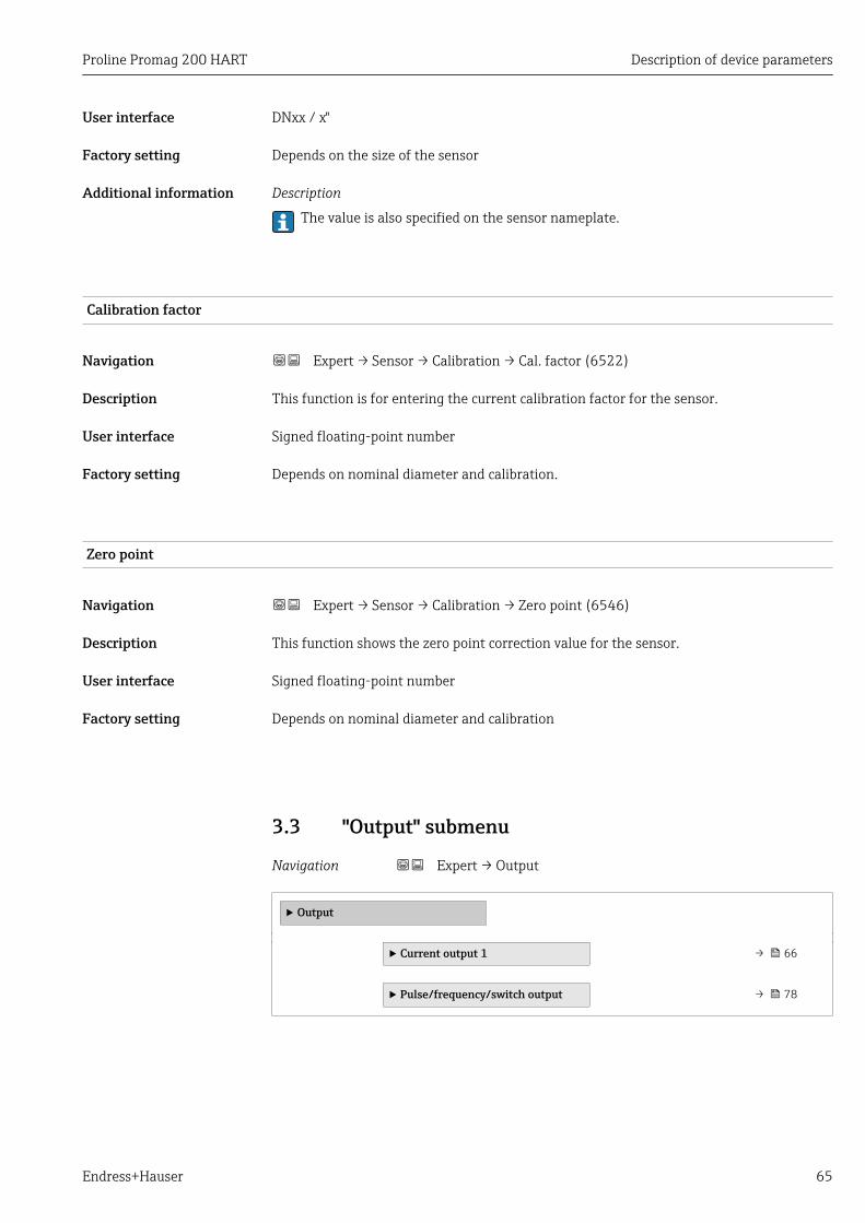
Proline Promag 200 HART Description of device parameters
Endress+Hauser 65
User interface DNxx / x"
Factory setting Depends on the size of the sensor
Additional information Description
The value is also specified on the sensor nameplate.
Calibration factor
Navigation Expert → Sensor → Calibration → Cal. factor (6522)
Description This function is for entering the current calibration factor for the sensor.
User interface Signed floating-point number
Factory setting Depends on nominal diameter and calibration.
Zero point
Navigation Expert → Sensor → Calibration → Zero point (6546)
Description This function shows the zero point correction value for the sensor.
User interface Signed floating-point number
Factory setting Depends on nominal diameter and calibration
3.3 "Output" submenu
Navigation Expert → Output
‣ Output
‣ Current output 1 → 66
‣ Pulse/frequency/switch output → 78

Description of device parameters Proline Promag 200 HART
66 Endress+Hauser
3.3.1 "Current output 1" submenu
Navigation Expert → Output → Curr.output 1
‣ Current output 1
Assign current output (0359–1) → 66
Current span (0353–1) → 67
Fixed current (0365–1) → 68
4 mA value (0367–1) → 68
20 mA value (0372–1) → 70
Measuring mode (0351–1) → 70
Damping output (0363–1) → 74
Failure mode (0364–1) → 75
Failure current (0352–1) → 76
Output current 1 (0361–1) → 76
Start-up mode (0368–1) → 76
Start-up current (0369–1) → 77
Measured current 1 (0366–1) → 77
Terminal voltage 1 (0662–1) → 77
Assign current output
Navigation Expert → Output → Curr.output 1 → Assign curr. (0359–1)
Description Options for the assignment of a process variable to the current output.
Selection • Off• Volume flow• Mass flow
Factory setting Volume flow

Proline Promag 200 HART Description of device parameters
Endress+Hauser 67
Current span
Navigation Expert → Output → Curr.output 1 → Current span (0353–1)
Description The selection specifies the operational range for the process value and the upper and lowerlevel for signal on alarm.
Selection • 4...20 mA NAMUR• 4...20 mA US• 4...20 mA• Fixed current
Factory setting Country-specific:• 4...20 mA NAMUR• 4...20 mA US
Additional information Description
• If an error occurs, the current output adopts the value defined in the Failure modeparameter (→ 75).
• If the measured value is outside the measuring range, the diagnostic messageS441 Current output 1 is displayed.
• The measuring range is specified by the 4 mA value parameter (→ 68) and 20mA value parameter (→ 70).
"Fixed current" option
The current value is set via the Fixed current parameter (→ 68).
Example
Shows the relationship between the current span for the output of the process variable andthe lower and upper alarm levels:
12 3
I [mA]
A0013316
I Current1 Current span for process value2 Lower level for signal on alarm3 Upper level for signal on alarm
Options 1 2 3
4 to 20 mA NAMUR 3.8 to 20.5 mA < 3.6 mA > 21.95 mA
4 to 20 mA US 3.9 to 20.8 mA US < 3.6 mA > 21.95 mA
4 to 20 mA 4 to 20.5 mA < 3.6 mA > 21.95 mA

Description of device parameters Proline Promag 200 HART
68 Endress+Hauser
Fixed current
Navigation Expert → Output → Curr.output 1 → Fixed current (0365–1)
Prerequsite The Fixed current option is selected in the Current span parameter (→ 67).
Description Use this function to enter a constant current value for the current output.
User entry 3.59 to 22.5 mA
Factory setting 4 mA
Additional information Example
This setting can be used for HART multidrop, for example.
4 mA value
Navigation Expert → Output → Curr.output 1 → 4 mA value (0367–1)
Prerequsite In the Current span parameter (→ 67), one of the following options is selected:• 4...20 mA NAMUR• 4...20 mA US• 4...20 mA
Description Use this function to enter a value for the 4 mA current.
User entry Signed floating-point number
Factory setting Country-specific:• 0 l/h• 0 gal/min (us)
Additional information Description
Positive and negative values are permitted depending on the process variable assigned inthe Assign current output parameter (→ 66). In addition, the value can be greater orsmaller than the value assigned for the 20mA current in the 20 mA value parameter(→ 70).
User entry
The unit depends on the process variable selected in the Assign current output parameter(→ 66).
Current output behavior
The current output behaves differently depending on the settings configured in thefollowing parameters:• Current span (→ 67)• Measuring mode (→ 70)• Failure mode (→ 75)

Proline Promag 200 HART Description of device parameters
Endress+Hauser 69
Configuration examples
Some examples of parameter settings and their effect on the current output are given inthe following section.
Configuration example AMeasuring mode with the Forward flow option• 4 mA value parameter (→ 68) = not equal to zero flow (e.g. –250 m3/h)• 20 mA value parameter (→ 70) = not equal to zero flow (e.g. +750 m3/h)• Calculated current value = 8 mA at zero flow
-250
20
+750
I [mA]
Q
1 1
4
0
8
A0013757
Q FlowI Current1 Measuring range is exceeded or undershot
The operational range of the measuring device is defined by the values entered for the 4mA value parameter (→ 68) and 20 mA value parameter (→ 70). If the effectiveflow falls outside this operational range, the diagnostic message S441 Current output 1is displayed.
Configuration example BMeasuring mode with the Forward/Reverse flow option
Q
20
0
I [mA]
4
3 1 2
0
A0013758
I CurrentQ Flow1 Value assigned to 4 mA current2 Forward flow3 Reverse flow
The current output signal is independent of the direction of flow (absolute amount of themeasured variable). The values for the 4 mA value parameter (→ 68) and 20 mAvalue parameter (→ 70) must have the same sign. The value for the 20 mA valueparameter (→ 70) (e.g. reverse flow) corresponds to the mirrored value for the 20mA value parameter (→ 70) (e.g. forward flow).
Configuration example CMeasuring mode with Reverse flow compensation optionIf flow is characterized by severe fluctuations (e.g. when using reciprocating pumps), flowcomponents outside of the measuring range are buffered, balanced and output after amaximum delay of 60 s → 70.

Description of device parameters Proline Promag 200 HART
70 Endress+Hauser
20 mA value
Navigation Expert → Output → Curr.output 1 → 20 mA value (0372–1)
Prerequsite In the Current span parameter (→ 67), one of the following options is selected:• 4...20 mA NAMUR• 4...20 mA US• 4...20 mA
Description Enter a value for the 20 mA current.
User entry Signed floating-point number
Factory setting Depends on country and nominal diameter → 142
Additional information Description
Positive and negative values are permitted depending on the process variable assigned inthe Assign current output parameter (→ 66). In addition, the value can be greater orsmaller than the value assigned for the 4 mA current in the 4 mA value parameter(→ 68).
User entry
The unit depends on the process variable selected in the Assign current output parameter(→ 66).
Example
• Value assigned for 4 mA = –250 m3/h• Value assigned for 20 mA = +750 m3/h• Calculated current value = 8 mA (at zero flow)
If the Forward/Reverse flow option is selected in the Measuring mode parameter(→ 70), different signs cannot be entered for the values of the 4 mA value parameter(→ 68) and 20 mA value parameter (→ 70). The diagnostic messageS441 Current output 1 is displayed.
Pay attention to the configuration examples for the 4 mA value parameter(→ 68).
Measuring mode
Navigation Expert → Output → Curr.output 1 → Measuring mode (0351–1)
Prerequsite In the Assign current output parameter (→ 66), one of the following options isselected:• Volume flow• Mass flow
In the Current span parameter (→ 67), one of the following options is selected:• 4...20 mA NAMUR• 4...20 mA US• 4...20 mA
Description Use this function to select the measuring mode for the current output.

Proline Promag 200 HART Description of device parameters
Endress+Hauser 71
Selection • Forward flow• Forward/Reverse flow• Reverse flow compensation
Factory setting Forward flow
Additional information Description
The process variable that is assigned to the current output via the Assign currentoutput parameter (→ 66) is displayed below the parameter.
"Forward flow" option
The current output signal is proportional to the process variable assigned. The measuringrange is defined by the values that are assigned to the 4 mA and 20 mA current value. Theflow components outside the scaled measuring range are taken into account for signaloutput as follows:
Both values are defined such that they are not equal to zero flow (e.g. 4 mA current value= –5 m3/h, 20 mA current value = 10 m3/h): if the effective flow falls outside thismeasuring range, the diagnostic message S441 Current output 1 is displayed.
"Forward/Reverse flow" option
Q
20
0
I [mA]
4
3 1 2
0
A0013758
I CurrentQ Flow1 Value assigned to 4 mA current2 Forward flow3 Reverse flow
The current output signal is independent of the direction of flow (absolute amount of themeasured variable). The values for the 4 mA value parameter (→ 68) and 20 mAvalue parameter (→ 70) must have the same sign. The value for the 20 mA valueparameter (→ 70) (e.g. reverse flow) corresponds to the mirrored value for the 20 mAvalue parameter (→ 70) (e.g. forward flow).
"Reverse flow compensation" option
If flow is characterized by severe fluctuations (e.g. when using reciprocating pumps), flowcomponents outside of the measuring range are buffered, balanced and output after amaximum delay of 60 s .
If buffering is not processed within approx. 60 s, the diagnostic message S441 Currentoutput 1 is displayed.
Under certain plant conditions, flow values can aggregate in the buffer, for example in thecase of prolonged and unwanted fluid reverse flow. However, this buffer is reset in allrelevant programming adjustments which affect the current output.
Examples of how the current output behaves
Example 1Defined measuring range: lower range value and upper range value with the same sign

Description of device parameters Proline Promag 200 HART
72 Endress+Hauser
Q
20
40
I [mA]
1 2
A0001248
4 Measuring range
I CurrentQ Flow1 Lower range value (value assigned to 4 mA current)2 Upper range value (value assigned to 20 mA current)
With the following flow response:
t
Q
A0001265
5 Flow response
Q Flowt Time
With the Forward flow option
The current output signal is proportional to the process variable assigned. The flowcomponents outside the scaled measuring range are not taken into account for signaloutput:.
t
I [mA]
A0001267
I Currentt Time
With the Forward/Reverse flow option
The current output signal is independent of the direction of flow.
t
I [mA]
A0001268
I Currentt Time
With the Reverse flow compensation option

Proline Promag 200 HART Description of device parameters
Endress+Hauser 73
Flow components outside the span are buffered, balanced and output after a maximumdelay of 60 s .
t
S = A
A
S
I [mA]
A0001269
I Currentt TimeS Flow components savedA Balancing of saved flow components
Example 2Defined measuring range: lower range value and upper range value with different signs
20
00
I [mA]
4Q
1 2
A0001272
6 Measuring range
I CurrentQ Flow1 Lower range value (value assigned to 4 mA current)2 Upper range value (value assigned to 20 mA current)
With flow a (—) outside, b (- -) inside the measuring range
t
a
b
Q
0
+
1
2
-
A0001273
Q Flowt Time1 Lower range value (value assigned to 4 mA current)2 Upper range value (value assigned to 20 mA current)
With the Forward flow option
• a (—): The flow components outside the scaled measuring range cannot be taken intoaccount for signal output.The diagnostic message S441 Current output 1 is displayed.
• b (····): The current output signal is proportional to the process variable assigned.

Description of device parameters Proline Promag 200 HART
74 Endress+Hauser
t
I [mA]
A0001274
I Currentt Time
With the Forward/Reverse flow option
This option is not possible in this case because the values for the 4 mA value parameter(→ 68) and 20 mA value parameter (→ 70) have different signs.
With the Reverse flow compensation option
Flow components outside the span are buffered, balanced and output after a maximumdelay of 60 s.
t
I [mA]
S = AS
A
A0001275
I Currentt TimeS Flow components savedA Balancing of saved flow components
Damping output
Navigation Expert → Output → Curr.output 1 → Damping out. (0363–1)
Prerequsite In the Assign current output parameter (→ 66), one of the following options isselected:• Volume flow• Mass flow
In the Current span parameter (→ 67), one of the following options is selected:• 4...20 mA NAMUR• 4...20 mA US• 4...20 mA
Description Use this function to enter the reaction time of the current output signal to fluctuations inthe measured value caused by process conditions.
User entry 0.0 to 999.9 s
Factory setting 1.0 s
Proline Promag 200 HART Description of device parameters
Endress+Hauser 75
Additional information Description
Entry of a time constant:• If a low time constant is entered, the current output reacts particularly quickly to
fluctuating measured variables.• On the other hand, the current output reacts more slowly if a high time constant is
entered.
Failure mode
Navigation Expert → Output → Curr.output 1 → Failure mode (0364–1)
Prerequsite In the Assign current output parameter (→ 66), one of the following options isselected:• Volume flow• Mass flow
In the Current span parameter (→ 67), one of the following options is selected:• 4...20 mA NAMUR• 4...20 mA US• 4...20 mA
Description Use this function to select the value of the current output in the event of an alarmcondition.
Selection • Min.• Max.• Last valid value• Actual value• Defined value
Factory setting Max.
Additional information Description
This setting does not affect the failsafe mode of other outputs and totalizers. This isspecified in separate parameters.
"Min." option
The current output adopts the value of the lower level for signal on alarm.
The signal on alarm level is defined via the Current span parameter (→ 67).
"Max." option
The current output adopts the value of the upper level for signal on alarm.
The signal on alarm level is defined via the Current span parameter (→ 67).
"Last valid value" option
The current output is based on the last measured value that was valid before the erroroccurred.
"Actual value" option
The current output is based on the actual measured value on the basis of the current flowmeasurement; the error is ignored.

Description of device parameters Proline Promag 200 HART
76 Endress+Hauser
"Defined value" option
The current output adopts a defined measured value.
The measured value is defined via the Failure current parameter (→ 76).
Failure current
Navigation Expert → Output → Curr.output 1 → Failure current (0352–1)
Prerequsite The Defined value option is selected in the Failure mode parameter (→ 75).
Description Use this function to enter a fixed value that the current output adopts in an alarmcondition.
User entry 3.59 to 22.5 mA
Factory setting 22.5 mA
Output current 1
Navigation Expert → Output → Curr.output 1 → Output curr. 1 (0361–1)
Description Use this function to view the actual calculated value of the output current.
User interface 3.59 to 22.5 mA
Factory setting 3.59 mA
Start-up mode
Navigation Expert → Output → Curr.output 1 → Start-up mode (0368–1)
Prerequsite In the Current span parameter (→ 67), one of the following options is selected:• 4...20 mA NAMUR• 4...20 mA US• 4...20 mA
Description Use this function to select the current value that the current output adopts during thedevice start-up phase as long as no measured value is present.
Selection • Min.• Max.• Defined value
Factory setting Min.

Proline Promag 200 HART Description of device parameters
Endress+Hauser 77
Additional information "Min." option
The current output adopts the value of the lower level for signal on alarm.
The signal on alarm level is defined via the Current span parameter (→ 67).
"Max." option
The current output adopts the value of the upper level for signal on alarm.
The signal on alarm level is defined via the Current span parameter (→ 67).
"Defined value" option
The current output outputs a defined current value.
The current value is defined via the Start-up current parameter (→ 77).
Start-up current
Navigation Expert → Output → Curr.output 1 → Start-up current (0369–1)
Prerequsite The Defined value option is selected in the Start-up mode parameter (→ 76).
Description Use this function to enter a fixed current value that the current output adopts during thedevice start-up phase as long as no measured value is present.
User entry 3.59 to 22.5 mA
Factory setting 3.6 mA
Measured current 1
Navigation Expert → Output → Curr.output 1 → Measur. curr. 1 (0366–1)
Description Use this function to display the actual measured value of the output current.
User interface 0 to 30 mA
Terminal voltage 1
Navigation Expert → Output → Curr.output 1 → Terminal volt. 1 (0662–1)
Description Use this function to view the actual terminal voltage that is present at the current output.
User interface 0.0 to 50.0 V

Description of device parameters Proline Promag 200 HART
78 Endress+Hauser
3.3.2 "Pulse/frequency/switch output" submenu
Navigation Expert → Output → PFS output
‣ Pulse/frequency/switch output
Operating mode (0469) → 79
Assign pulse output (0460) → 79
Value per pulse (0455) → 80
Pulse width (0452) → 80
Measuring mode (0457) → 80
Failure mode (0480) → 81
Pulse output (0456) → 81
Assign frequency output (0478) → 82
Minimum frequency value (0453) → 82
Maximum frequency value (0454) → 82
Measuring value at minimumfrequency (0476)
→ 83
Measuring value at maximumfrequency (0475)
→ 83
Measuring mode (0479) → 84
Damping output (0477) → 84
Failure mode (0451) → 84
Failure frequency (0474) → 85
Output frequency (0471) → 85
Switch output function (0481) → 85
Assign diagnostic behavior (0482) → 86
Assign limit (0483) → 86
Switch-on value (0466) → 86

Proline Promag 200 HART Description of device parameters
Endress+Hauser 79
Switch-off value (0464) → 87
Assign flow direction check (0484) → 87
Assign status (0485) → 87
Switch-on delay (0467) → 88
Switch-off delay (0465) → 88
Failure mode (0486) → 88
Switch status (0461) → 88
Invert output signal (0470) → 89
Operating mode
Navigation Expert → Output → PFS output → Operating mode (0469)
Description Use this function to select the operating mode of the output as a pulse, frequency or switchoutput.
Selection • Pulse• Frequency• Switch
Factory setting Pulse
Assign pulse output
Navigation Expert → Output → PFS output → Assign pulse (0460)
Prerequsite The Pulse option is selected in the Operating mode parameter (→ 79).
Description Use this function to select the process variable for the pulse output.
Selection • Off• Mass flow• Volume flow
Factory setting Off

Description of device parameters Proline Promag 200 HART
80 Endress+Hauser
Value per pulse
Navigation Expert → Output → PFS output → Value per pulse (0455)
Prerequsite In the Assign pulse output parameter (→ 79), one of the following options is selected:• Mass flow• Volume flow
Description Use this function to enter the measured value for the pulse output.
User entry Signed floating-point number
Factory setting 0
Pulse width
Navigation Expert → Output → PFS output → Pulse width (0452)
Prerequsite In the Assign pulse output parameter (→ 79), one of the following options is selected:• Mass flow• Volume flow
Description Use this function to enter the duration of the output pulse.
User entry 5 to 2 000 ms
Factory setting 100 ms
Measuring mode
Navigation Expert → Output → PFS output → Measuring mode (0457)
Prerequsite In the Assign pulse output parameter (→ 79), one of the following options is selected:• Mass flow• Volume flow
Description Use this function to select the measuring mode for the pulse output.
Selection • Forward flow• Forward/Reverse flow• Reverse flow• Reverse flow compensation
Factory setting Forward flow

Proline Promag 200 HART Description of device parameters
Endress+Hauser 81
Failure mode
Navigation Expert → Output → PFS output → Failure mode (0480)
Prerequsite In the Assign pulse output parameter (→ 79), one of the following options is selected:• Mass flow• Volume flow
Description Use this function to select an output behavior in the event of a device alarm.
Selection • Actual value• No pulses
Factory setting No pulses
Pulse output
Navigation Expert → Output → PFS output → Pulse output (0456)
Prerequsite The Pulse option is selected in the Operating mode parameter (→ 79).
Description Use this function to display the pulse frequency currently output.
User interface Positive floating-point number
Additional information Description
The pulse output is an open collector output. This is configured at the factory so that thetransistor is conductive for the duration of the pulse (NO contact).
With the Value per pulse parameter (→ 80) and Pulse width parameter (→ 80) itis possible to define the value - i.e. the measured value amount that is equivalent to apulse, and the duration of the pulse.
1
0
1
0
NC
NO
A0025816-EN
0 Non-conductive1 ConductiveNC Normally closedNO Normally opened

Description of device parameters Proline Promag 200 HART
82 Endress+Hauser
The output behavior can be inverted via the Invert output signal parameter (→ 89),i.e. the transistor is not conductive for the duration of the pulse.
In addition, the behavior of the output in the event of an error (Failure mode parameter(→ 81)) can be configured.
Assign frequency output
Navigation Expert → Output → PFS output → Assign freq. (0478)
Prerequsite The Frequency option is selected in the Operating mode parameter (→ 79).
Description Use this function to select the process variable for the frequency output.
Selection • Off• Volume flow• Mass flow
Factory setting Off
Minimum frequency value
Navigation Expert → Output → PFS output → Min. freq. value (0453)
Prerequsite In the Assign frequency output parameter (→ 82), one of the following options isselected:• Volume flow• Mass flow
Description Use this function to enter the start value frequency.
User entry 0 to 1 000 Hz
Factory setting 0 Hz
Maximum frequency value
Navigation Expert → Output → PFS output → Max. freq. value (0454)
Prerequsite In the Assign frequency output parameter (→ 82), one of the following options isselected:• Volume flow• Mass flow
Description Use this function to enter the end value frequency.
User entry 0 to 1 000 Hz

Proline Promag 200 HART Description of device parameters
Endress+Hauser 83
Factory setting 1 000 Hz
Measuring value at minimum frequency
Navigation Expert → Output → PFS output → Val. at min.freq (0476)
Prerequsite In the Assign frequency output parameter (→ 82), one of the following options isselected:• Volume flow• Mass flow
Description Use this function to enter the measured value for the start value frequency.
User entry Signed floating-point number
Factory setting Depends on country and nominal diameter
Additional information Dependency
The unit depends on the process variable selected in the Assign frequency outputparameter (→ 82).
Measuring value at maximum frequency
Navigation Expert → Output → PFS output → Val. at max.freq (0475)
Prerequsite In the Assign frequency output parameter (→ 82), one of the following options isselected:• Volume flow• Mass flow
Description Use this function to enter the measured value for the end value frequency.
User entry Signed floating-point number
Factory setting Depends on country and nominal diameter
Additional information Dependency
The unit depends on the process variable selected in the Assign frequency outputparameter (→ 82).

Description of device parameters Proline Promag 200 HART
84 Endress+Hauser
Measuring mode
Navigation Expert → Output → PFS output → Measuring mode (0479)
Prerequsite In the Assign frequency output parameter (→ 82), one of the following options isselected:• Volume flow• Mass flow
Description Use this function to select the measuring mode for the frequency output.
Selection • Forward flow• Forward/Reverse flow• Reverse flow compensation
Factory setting Forward flow
Damping output
Navigation Expert → Output → PFS output → Damping out. (0477)
Prerequsite In the Assign frequency output parameter (→ 82), one of the following options isselected:• Volume flow• Mass flow
Description Use this function to enter the reaction time of the output signal to fluctuations in themeasured value.
User entry 0 to 999.9 s
Factory setting 0.0 s
Failure mode
Navigation Expert → Output → PFS output → Failure mode (0451)
Prerequsite In the Assign frequency output parameter (→ 82), one of the following options isselected:• Volume flow• Mass flow
Description Use this function to select an output behavior in the event of a device alarm.
Selection • Actual value• Defined value• 0 Hz
Factory setting 0 Hz

Proline Promag 200 HART Description of device parameters
Endress+Hauser 85
Failure frequency
Navigation Expert → Output → PFS output → Failure freq. (0474)
Prerequsite In the Assign frequency output parameter (→ 82), one of the following options isselected:• Volume flow• Mass flow
Description Use this function to enter the value for the frequency output in the event of a device alarm.
User entry 0.0 to 1 250.0 Hz
Factory setting 0.0 Hz
Output frequency
Navigation Expert → Output → PFS output → Output freq. (0471)
Prerequsite The Frequency option is selected in the Operating mode parameter (→ 79).
Description Use this function to view the actual value of the output frequency which is currentlymeasured.
User interface 0 to 1 250 Hz
Switch output function
Navigation Expert → Output → PFS output → Switch out funct (0481)
Prerequsite The Switch option is selected in the Operating mode parameter (→ 79).
Description Use this function to select a function for the switch output.
Selection • Off• On• Diagnostic behavior• Limit• Flow direction check• Status
Factory setting Off

Description of device parameters Proline Promag 200 HART
86 Endress+Hauser
Assign diagnostic behavior
Navigation Expert → Output → PFS output → Assign diag. beh (0482)
Prerequsite The Diagnostic behavior option is selected in the Switch output function parameter(→ 85).
Description Use this function to select a diagnostic behavior for the switch output.
Selection • Alarm• Alarm or warning• Warning
Factory setting Alarm
Assign limit
Navigation Expert → Output → PFS output → Assign limit (0483)
Prerequsite The Limit option is selected in the Switch output function parameter (→ 85).
Description Use this function to select a process variable for the limit function.
Selection • Volume flow• Mass flow• Totalizer 1• Totalizer 2• Totalizer 3
Factory setting Volume flow
Switch-on value
Navigation Expert → Output → PFS output → Switch-on value (0466)
Prerequsite The Limit option is selected in the Switch output function parameter (→ 85).
Description Use this function to enter the measured value for the switch-on point.
User entry Signed floating-point number
Factory setting Country-specific:• 0 l/h• 0 gal/min (us)
Additional information Dependency
The unit depends on the process variable selected in the Assign limit parameter(→ 86).

Proline Promag 200 HART Description of device parameters
Endress+Hauser 87
Switch-off value
Navigation Expert → Output → PFS output → Switch-off value (0464)
Prerequsite The Limit option is selected in the Switch output function parameter (→ 85).
Description Use this function to enter the measured value for the switch-off point.
User entry Signed floating-point number
Factory setting Country-specific:• 0 l/h• 0 gal/min (us)
Additional information Dependency
The unit depends on the process variable selected in the Assign limit parameter(→ 86).
Assign flow direction check
Navigation Expert → Output → PFS output → Assign dir.check (0484)
Prerequsite The Flow direction check option is selected in the Switch output function parameter(→ 85).
Description Use this function to select a process variable for monitoring the flow direction.
Selection • Volume flow• Mass flow
Factory setting Volume flow
Assign status
Navigation Expert → Output → PFS output → Assign status (0485)
Prerequsite The Status option is selected in the Switch output function parameter (→ 85).
Description Use this function to select a device status for the switch output.
Selection • Empty pipe detection• Low flow cut off
Factory setting Empty pipe detection

Description of device parameters Proline Promag 200 HART
88 Endress+Hauser
Switch-on delay
Navigation Expert → Output → PFS output → Switch-on delay (0467)
Prerequsite The Limit option is selected in the Switch output function parameter (→ 85).
Description Use this function to enter a delay time for switching on the switch output.
User entry 0.0 to 100.0 s
Factory setting 0.0 s
Switch-off delay
Navigation Expert → Output → PFS output → Switch-off delay (0465)
Prerequsite The Limit option is selected in the Switch output function parameter (→ 85).
Description Use this function to enter a delay time for switching off the switch output.
User entry 0.0 to 100.0 s
Factory setting 0.0 s
Failure mode
Navigation Expert → Output → PFS output → Failure mode (0486)
Description Use this function to select an output behavior in the event of a device alarm.
Selection • Actual status• Open• Closed
Factory setting Open
Switch status
Navigation Expert → Output → PFS output → Switch status (0461)
Prerequsite The Switch option is selected in the Operating mode parameter (→ 79).
Description Use this function to view the current switch status of the status output.

Proline Promag 200 HART Description of device parameters
Endress+Hauser 89
User interface • Open• Closed
Invert output signal
Navigation Expert → Output → PFS output → Invert outp.sig. (0470)
Description Use this function to select whether to invert the output signal.
Selection • No• Yes
Factory setting No
3.4 "Communication" submenu
Navigation Expert → Communication
‣ Communication
‣ HART output → 89
‣ Diagnostic configuration → 103
3.4.1 "HART output" submenu
Navigation Expert → Communication → HART output
‣ HART output
‣ Configuration → 90
‣ Burst configuration → 91
‣ Information → 97
‣ Output → 100

Description of device parameters Proline Promag 200 HART
90 Endress+Hauser
"Configuration" submenu
Navigation Expert → Communication → HART output → Configuration
‣ Configuration
HART short tag (0220) → 90
Device tag (0215) → 90
HART address (0219) → 90
No. of preambles (0217) → 91
HART short tag
Navigation Expert → Communication → HART output → Configuration → HART short tag(0220)
Description Use this function to enter a brief description for the measuring point. This can be editedand displayed via HART protocol or using the local display.
User entry Max. 8 characters: A-Z, 0-9 and certain special characters (e.g. punctuation marks, @, %).
Factory setting PROMAG
Device tag
Navigation Expert → Communication → HART output → Configuration → Device tag (0215)
Description Use this function to enter the name for the measuring point.
User entry Max. 32 characters such as letters, numbers or special characters (e.g. @, %, /).
Factory setting Promag
HART address
Navigation Expert → Communication → HART output → Configuration → HART address (0219)
Description Use this function to enter the address via which the data exchange takes place via HARTprotocol.
User entry 0 to 63

Proline Promag 200 HART Description of device parameters
Endress+Hauser 91
Factory setting 0
No. of preambles
Navigation Expert → Communication → HART output → Configuration → No. of preambles(0217)
Description Use this function to enter the number of preambles in the HART protocol.
User entry 2 to 20
Factory setting 5
Additional information User entry
As every modem component can "swallow" a byte, 2-byte preambles at least must bedefined.
"Burst configuration" submenu
Navigation Expert → Communication → HART output → Burst config.→ Burst config. 1 to 3
‣ Burst configuration
‣ Burst configuration 1 to 3
Burst mode 1 to 3 (2032–1 to 3) → 92
Burst command 1 to 3 (2031–1 to 3) → 92
Burst variable 0 (2033–1 to 3) → 93
Burst variable 1 (2034–1 to 3) → 94
Burst variable 2 (2035–1 to 3) → 94
Burst variable 3 (2036–1 to 3) → 94
Burst variable 4 (2037–1 to 3) → 94
Burst variable 5 (2038–1 to 3) → 95
Burst variable 6 (2039–1 to 3) → 95
Burst variable 7 (2040–1 to 3) → 95

Description of device parameters Proline Promag 200 HART
92 Endress+Hauser
Burst trigger mode (2044–1 to 3) → 95
Burst trigger level (2043–1 to 3) → 96
Min. update period (2042–1 to 3) → 96
Max. update period (2041–1 to 3) → 97
Burst mode 1 to 3
Navigation Expert → Communication → HART output → Burst config. → Burst config. 1 to 3→ Burst mode 1 to 3 (2032–1 to 3)
Description Use this function to select whether to activate the HART burst mode for burst message X.
Selection • Off• On
Factory setting Off
Additional information Selection
• OffThe measuring device transmits data only when requested by the HART master.
• OnThe measuring device transmits data regularly without being requested.
Burst command 1 to 3
Navigation Expert → Communication → HART output → Burst config. → Burst config. 1 to 3→ Burst command 1 to 3 (2031–1 to 3)
Description Use this function to select the HART command that is sent to the HART master.
Selection • Command 1• Command 2• Command 3• Command 9• Command 33• Command 48
Factory setting Command 2

Proline Promag 200 HART Description of device parameters
Endress+Hauser 93
Additional information Selection
• Command 1Read out the primary variable.
• Command 2Read out the current and the main measured value as a percentage.
• Command 3Read out the dynamic HART variables and the current.
• Command 9Read out the dynamic HART variables including the related status.
• Command 33Read out the dynamic HART variables including the related unit.The HART device variables are defined via Command 107.The following measured variables (HART device variables) can be read out:– Volume flow– Mass flow– Totalizer 1…3– Percent Of Range– Measured current– Primary variable (PV)– Secondary variable (SV)– Tertiary variable (TV)– Quaternary variable (QV)
• Command 48Read out the complete device diagnostics.
Commands
Information about the defined details of the command: HART specifications
The measured variables (HART device variables) are assigned to the dynamicvariables in the Output submenu (→ 65).
Burst variable 0
Navigation Expert → Communication → HART output → Burst config. → Burst config. 1 to 3→ Burst variable 0 (2033–1 to 3)
Description For HART command 9 and 33: select the HART device variable or the process variable.
Selection • Volume flow• Mass flow• Totalizer 1• Totalizer 2• Totalizer 3• Percent Of Range• Measured current• Primary variable (PV)• Secondary variable (SV)• Tertiary variable (TV)• Quaternary variable (QV)• Not used
Factory setting Volume flow

Description of device parameters Proline Promag 200 HART
94 Endress+Hauser
Burst variable 1
Navigation Expert → Communication → HART output → Burst config. → Burst config. 1 to 3→ Burst variable 1 (2034–1 to 3)
Description For HART command 9 and 33: select the HART device variable or the process variable.
Selection See Burst variable 0 parameter (→ 93).
Factory setting Not used
Burst variable 2
Navigation Expert → Communication → HART output → Burst config. → Burst config. 1 to 3→ Burst variable 2 (2035–1 to 3)
Description For HART command 9 and 33: select the HART device variable or the process variable.
Selection See Burst variable 0 parameter (→ 93).
Factory setting Not used
Burst variable 3
Navigation Expert → Communication → HART output → Burst config. → Burst config. 1 to 3→ Burst variable 3 (2036–1 to 3)
Description For HART command 9 and 33: select the HART device variable or the process variable.
Selection See Burst variable 0 parameter (→ 93).
Factory setting Not used
Burst variable 4
Navigation Expert → Communication → HART output → Burst config. → Burst config. 1 to 3→ Burst variable 4 (2037–1 to 3)
Description For HART command 33: select the HART device variable or the process variable.
Selection See Burst variable 0 parameter (→ 93).
Factory setting Not used

Proline Promag 200 HART Description of device parameters
Endress+Hauser 95
Burst variable 5
Navigation Expert → Communication → HART output → Burst config. → Burst config. 1 to 3→ Burst variable 5 (2038–1 to 3)
Description For HART command 33: select the HART device variable or the process variable.
Selection See Burst variable 0 parameter (→ 93).
Factory setting Not used
Burst variable 6
Navigation Expert → Communication → HART output → Burst config. → Burst config. 1 to 3→ Burst variable 6 (2039–1 to 3)
Description For HART command 33: select the HART device variable or the process variable.
Selection See Burst variable 0 parameter (→ 93).
Factory setting Not used
Burst variable 7
Navigation Expert → Communication → HART output → Burst config. → Burst config. 1 to 3→ Burst variable 7 (2040–1 to 3)
Description For HART command 33: select the HART device variable or the process variable.
Selection See Burst variable 0 parameter (→ 93).
Factory setting Not used
Burst trigger mode
Navigation Expert → Communication → HART output → Burst config. → Burst config. 1 to 3→ Trigger mode (2044–1 to 3)
Description Use this function to select the event that triggers burst message X.
Selection • Continuous• Window• Rising• Falling• On change

Description of device parameters Proline Promag 200 HART
96 Endress+Hauser
Factory setting Continuous
Additional information Selection
• ContinuousThe message is triggered in a time-controlled manner, at least observing the timeinterval defined in the Burst min period parameter (→ 96).
• WindowThe message is triggered if the specified measured value has changed by the value in theBurst trigger level parameter (→ 96).
• RisingThe message is triggered if the specified measured value exceeds the value in the Bursttrigger level parameter (→ 96).
• FallingThe message is triggered if the specified measured value drops below the value in theBurst trigger level parameter (→ 96).
• On changeThe message is triggered if the measured value changes.
Burst trigger level
Navigation Expert → Communication → HART output → Burst config. → Burst config. 1 to 3→ Trigger level (2043–1 to 3)
Description For entering the burst trigger value.
User entry Positive floating-point number
Additional information Description
Together with the option selected in the Burst trigger mode parameter (→ 95) theburst trigger value determines the time of burst message X.
Min. update period
Navigation Expert → Communication → HART output → Burst config. → Burst config. 1 to 3→ Min. upd. per. (2042–1 to 3)
Description Use this function to enter the minimum time span between two burst commands of burstmessage X.
User entry Positive integer
Factory setting 1 000 ms
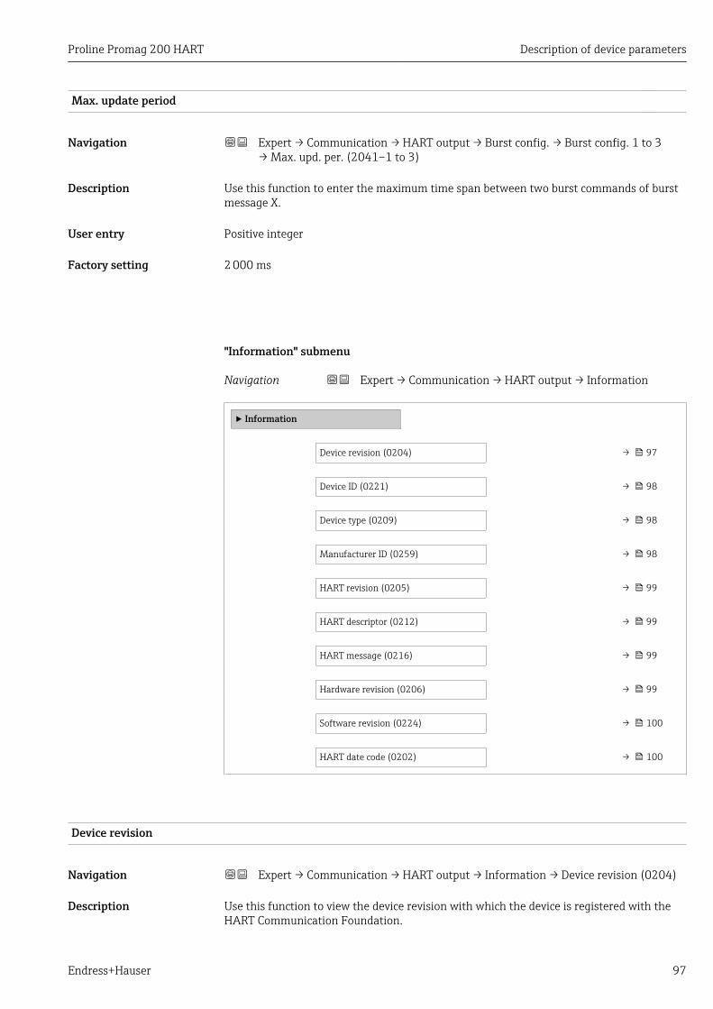
Proline Promag 200 HART Description of device parameters
Endress+Hauser 97
Max. update period
Navigation Expert → Communication → HART output → Burst config. → Burst config. 1 to 3→ Max. upd. per. (2041–1 to 3)
Description Use this function to enter the maximum time span between two burst commands of burstmessage X.
User entry Positive integer
Factory setting 2 000 ms
"Information" submenu
Navigation Expert → Communication → HART output → Information
‣ Information
Device revision (0204) → 97
Device ID (0221) → 98
Device type (0209) → 98
Manufacturer ID (0259) → 98
HART revision (0205) → 99
HART descriptor (0212) → 99
HART message (0216) → 99
Hardware revision (0206) → 99
Software revision (0224) → 100
HART date code (0202) → 100
Device revision
Navigation Expert → Communication → HART output → Information → Device revision (0204)
Description Use this function to view the device revision with which the device is registered with theHART Communication Foundation.

Description of device parameters Proline Promag 200 HART
98 Endress+Hauser
User interface 2-digit hexadecimal number
Factory setting 2
Additional information Description
The device revision is needed to assign the appropriate device description file (DD) tothe device.
Device ID
Navigation Expert → Communication → HART output → Information → Device ID (0221)
Description Use this function to view the device ID for identifying the measuring device in a HARTnetwork.
User interface 6-digit hexadecimal number
Additional information Description
In addition to the device type and manufacturer ID, the device ID is part of the uniqueID. Each HART device is uniquely identified by the unique device ID.
Device type
Navigation Expert → Communication → HART output → Information → Device type (0209)
Description Use this function to view the device type with which the measuring device is registeredwith the HART Communication Foundation.
User interface 2-digit hexadecimal number
Factory setting 0x48 (for Promag 200)
Additional information Description
The device type is specified by the manufacturer. It is needed to assign the appropriatedevice description file (DD) to the device.
Manufacturer ID
Navigation Expert → Communication → HART output → Information → Manufacturer ID (0259)
Description Use this function to view the manufacturer ID with which the measuring device isregistered with the HART Communication Foundation.
User interface 2-digit hexadecimal number

Proline Promag 200 HART Description of device parameters
Endress+Hauser 99
Factory setting 0x11 (for Endress+Hauser)
HART revision
Navigation Expert → Communication → HART output → Information → HART revision (0205)
Description Use this function to display the HART protocol revision of the measuring device.
User interface 5 to 7
Factory setting 7
HART descriptor
Navigation Expert → Communication → HART output → Information → HART descriptor (0212)
Description Use this function to enter a description for the measuring point. This can be edited anddisplayed via HART protocol or using the local display.
User entry Max. 16 characters such as letters, numbers or special characters (e.g. @, %, /)
Factory setting Promag
HART message
Navigation Expert → Communication → HART output → Information → HART message (0216)
Description Use this function to enter a HART message which is sent via the HART protocol whenrequested by the master.
User entry Max. 32 characters such as letters, numbers or special characters (e.g. @, %, /)
Factory setting Promag
Hardware revision
Navigation Expert → Communication → HART output → Information → Hardware rev. (0206)
Description Use this function to display the hardware revision of the measuring device.
User interface 0 to 255
Factory setting 1

Description of device parameters Proline Promag 200 HART
100 Endress+Hauser
Software revision
Navigation Expert → Communication → HART output → Information → Software rev. (0224)
Description Use this function to display the software revision of the measuring device.
User interface 0 to 255
Factory setting 2
HART date code
Navigation Expert → Communication → HART output → Information → HART date code (0202)
Description Use this function to enter the date information for individual use.
User entry Date entry format: yyyy-mm-dd
Factory setting 2009-07-20
Additional information Example
Device installation date
"Output" submenu
Navigation Expert → Communication → HART output → Output
‣ Output
Assign PV (0234) → 101
Primary variable (PV) (0201) → 101
Assign SV (0235) → 101
Secondary variable (SV) (0226) → 102
Assign TV (0236) → 102
Tertiary variable (TV) (0228) → 102
Assign QV (0237) → 103
Quaternary variable (QV) (0203) → 103

Proline Promag 200 HART Description of device parameters
Endress+Hauser 101
Assign PV
Navigation Expert → Communication → HART output → Output → Assign PV (0234)
Description Use this function to select the assignment of a measured variable (HART device variable)to the primary dynamic variable (PV).
Selection • Off• Volume flow• Mass flow
Factory setting Volume flow
Primary variable (PV)
Navigation Expert → Communication → HART output → Output → Primary var (PV) (0201)
Description Displays the current measured value of the primary dynamic variable (PV).
User interface Signed floating-point number
Additional information User interface
The displayed measured value depends on the option selected in the Assign PV parameter(→ 101).
The unit of the value is taken from the System units submenu (→ 45).
Assign SV
Navigation Expert → Communication → HART output → Output → Assign SV (0235)
Description Use this function to select the assignment of a measured variable (HART device variable)to the secondary dynamic variable (SV).
Selection • Volume flow• Mass flow• Totalizer 1• Totalizer 2• Totalizer 3
Factory setting Totalizer 1

Description of device parameters Proline Promag 200 HART
102 Endress+Hauser
Secondary variable (SV)
Navigation Expert → Communication → HART output → Output → Second.var(SV) (0226)
Description Displays the current measured value of the secondary dynamic variable (SV).
User interface Signed floating-point number
Additional information User interface
The displayed measured value depends on the option selected in the Assign SV parameter(→ 101).
The unit of the value is taken from the System units submenu (→ 45).
Assign TV
Navigation Expert → Communication → HART output → Output → Assign TV (0236)
Description Use this function to select the assignment of a measured variable (HART device variable)to the tertiary (third) dynamic variable (TV).
Selection • Volume flow• Mass flow• Totalizer 1• Totalizer 2• Totalizer 3
Factory setting Totalizer 2
Tertiary variable (TV)
Navigation Expert → Communication → HART output → Output → Tertiary var(TV) (0228)
Description Displays the current measured value of the tertiary dynamic variable (TV).
User interface Signed floating-point number
Additional information User interface
The displayed measured value depends on the option selected in the Assign TV parameter(→ 102).
The unit of the value is taken from the System units submenu (→ 45).

Proline Promag 200 HART Description of device parameters
Endress+Hauser 103
Assign QV
Navigation Expert → Communication → HART output → Output → Assign QV (0237)
Description Use this function to select the assignment of a measured variable (HART device variable)to the quaternary (fourth) dynamic variable (QV).
Selection • Volume flow• Mass flow• Totalizer 1• Totalizer 2• Totalizer 3
Factory setting Totalizer 3
Quaternary variable (QV)
Navigation Expert → Communication → HART output → Output → Quaterna.var(QV) (0203)
Description Displays the current measured value of the quaternary dynamic variable (QV).
User interface Signed floating-point number
Additional information User interface
The displayed measured value depends on the option selected in the Assign QV parameter(→ 103).
The unit of the value is taken from the System units submenu (→ 45).
3.4.2 "Diagnostic configuration" submenuFor a list of all the diagnostic events, see the Operating Instructions for the device.
Assign a category to the particular diagnostic event:• Failure (F) option
A device error has occurred. The measured value is no longer valid.• Function check (C) option
The device is in service mode (e.g. during a simulation).• Out of specification (S) option
The device is being operated:– Outside its technical specification limits (e.g. outside the process temperature
range)– Outside of the configuration carried out by the user (e.g. maximum flow in
parameter 20 mA value)• Maintenance required (M) option
Maintenance is required. The measured value is still valid.• No effect (N) option
Has no effect on the condensed status.

Description of device parameters Proline Promag 200 HART
104 Endress+Hauser
Navigation Expert → Communication → Diag. config.
‣ Diagnostic configuration
Event category 004 (0238) → 104
Event category 441 (0210) → 105
Event category 442 (0230) → 105
Event category 443 (0231) → 105
Event category 531 (0262) → 106
Event category 801 (0232) → 106
Event category 832 (0218) → 107
Event category 833 (0225) → 107
Event category 861 (0261) → 107
Event category 862 (0214) → 108
Event category 937 (0260) → 108
Event category 004 (Sensor)
Navigation Expert → Communication → Diag. config. → Event category 004 (0238)
Description Use this function to select the category assigned to diagnostic message 004 Sensor.
Selection • Failure (F)• Function check (C)• Out of specification (S)• Maintenance required (M)• No effect (N)
Factory setting Out of specification (S)
Additional information For a detailed description of the options available for selection: → 103

Proline Promag 200 HART Description of device parameters
Endress+Hauser 105
Event category 441 (Current output 1)
Navigation Expert → Communication → Diag. config. → Event category 441 (0210)
Description Use this function to select the category assigned to diagnostic message 441 Currentoutput 1.
Selection • Failure (F)• Function check (C)• Out of specification (S)• Maintenance required (M)• No effect (N)
Factory setting Out of specification (S)
Additional information For a detailed description of the options available for selection: → 103
Event category 442 (Frequency output)
Navigation Expert → Communication → Diag. config. → Event category 442 (0230)
Prerequsite The pulse/frequency/switch output is available.
Description Use this function to select the category assigned to diagnostic message 442 Frequencyoutput.
Selection • Failure (F)• Function check (C)• Out of specification (S)• Maintenance required (M)• No effect (N)
Factory setting Out of specification (S)
Additional information For a detailed description of the options available for selection: → 103
Event category 443 (Pulse output)
Navigation Expert → Communication → Diag. config. → Event category 443 (0231)
Prerequsite The pulse/frequency/switch output is available.
Description Use this function to select the category assigned to diagnostic message 443 Pulse output.

Description of device parameters Proline Promag 200 HART
106 Endress+Hauser
Selection • Failure (F)• Function check (C)• Out of specification (S)• Maintenance required (M)• No effect (N)
Factory setting Out of specification (S)
Additional information For a detailed description of the options available for selection: → 103
Event category 531 (Empty pipe detection)
Navigation Expert → Communication → Diag. config. → Event category 531 (0262)
Description Use this function to select the category assigned to diagnostic message 531 Empty pipedetection.
Selection • Failure (F)• Function check (C)• Out of specification (S)• Maintenance required (M)• No effect (N)
Factory setting Out of specification (S)
Additional information For a detailed description of the options available for selection: → 103
Event category 801 (Supply voltage too low)
Navigation Expert → Communication → Diag. config. → Event category 801 (0232)
Description Use this function to select the category assigned to diagnostic message 801 Supplyvoltage too low.
Selection • Failure (F)• Function check (C)• Out of specification (S)• Maintenance required (M)• No effect (N)
Factory setting Out of specification (S)
Additional information For a detailed description of the options available for selection: → 103
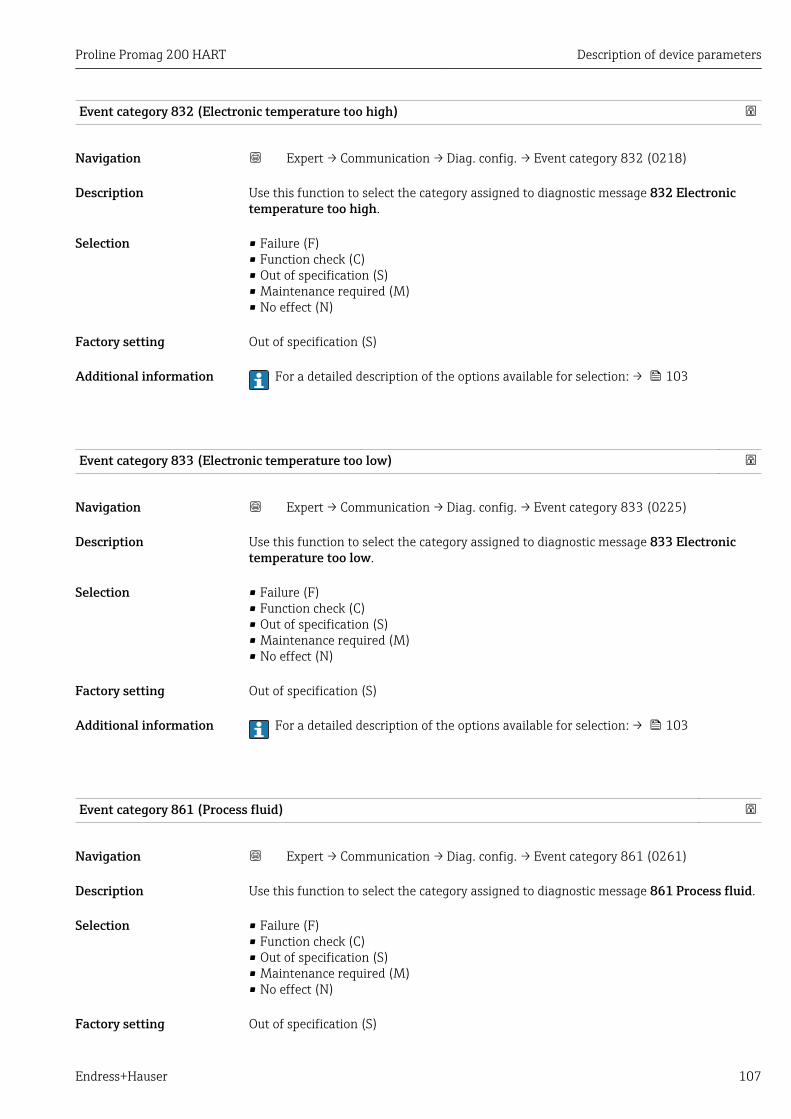
Proline Promag 200 HART Description of device parameters
Endress+Hauser 107
Event category 832 (Electronic temperature too high)
Navigation Expert → Communication → Diag. config. → Event category 832 (0218)
Description Use this function to select the category assigned to diagnostic message 832 Electronictemperature too high.
Selection • Failure (F)• Function check (C)• Out of specification (S)• Maintenance required (M)• No effect (N)
Factory setting Out of specification (S)
Additional information For a detailed description of the options available for selection: → 103
Event category 833 (Electronic temperature too low)
Navigation Expert → Communication → Diag. config. → Event category 833 (0225)
Description Use this function to select the category assigned to diagnostic message 833 Electronictemperature too low.
Selection • Failure (F)• Function check (C)• Out of specification (S)• Maintenance required (M)• No effect (N)
Factory setting Out of specification (S)
Additional information For a detailed description of the options available for selection: → 103
Event category 861 (Process fluid)
Navigation Expert → Communication → Diag. config. → Event category 861 (0261)
Description Use this function to select the category assigned to diagnostic message 861 Process fluid.
Selection • Failure (F)• Function check (C)• Out of specification (S)• Maintenance required (M)• No effect (N)
Factory setting Out of specification (S)

Description of device parameters Proline Promag 200 HART
108 Endress+Hauser
Additional information For a detailed description of the options available for selection: → 103
Event category 862 (Empty pipe)
Navigation Expert → Communication → Diag. config. → Event category 862 (0214)
Description Use this function to select the category assigned to diagnostic message 862 Empty pipe.
Selection • Failure (F)• Function check (C)• Out of specification (S)• Maintenance required (M)• No effect (N)
Factory setting Out of specification (S)
Additional information For a detailed description of the options available for selection: → 103
Event category 937 (EMC interference)
Navigation Expert → Communication → Diag. config. → Event category 937 (0260)
Description Use this function to select the category assigned to diagnostic message 937 EMCinterference.
Selection • Failure (F)• Function check (C)• Out of specification (S)• Maintenance required (M)• No effect (N)
Factory setting Out of specification (S)
Additional information For a detailed description of the options available for selection: → 103

Proline Promag 200 HART Description of device parameters
Endress+Hauser 109
3.5 "Application" submenu
Navigation Expert → Application
‣ Application
Reset all totalizers (2806) → 109
‣ Totalizer 1 to 3 → 109
Reset all totalizers
Navigation Expert → Application → Reset all tot. (2806)
Description Use this function to reset all totalizers to the value 0 and restart the totaling process. Thisdeletes all the flow values previously totalized.
Selection • Cancel• Reset + totalize
Factory setting Cancel
Additional information Selection
• CancelNo action is executed and the user exits the parameter.
• Reset + totalizeAll totalizers are reset to 0 and the totaling process is restarted.
3.5.1 "Totalizer 1 to 3" submenu
Navigation Expert → Application → Totalizer 1 to 3
‣ Totalizer 1 to 3
Assign process variable (0914–1 to 3) → 110
Unit totalizer (0915–1 to 3) → 110
Totalizer operation mode(0908–1 to 3)
→ 111
Control Totalizer 1 to 3 (0912–1 to 3) → 112
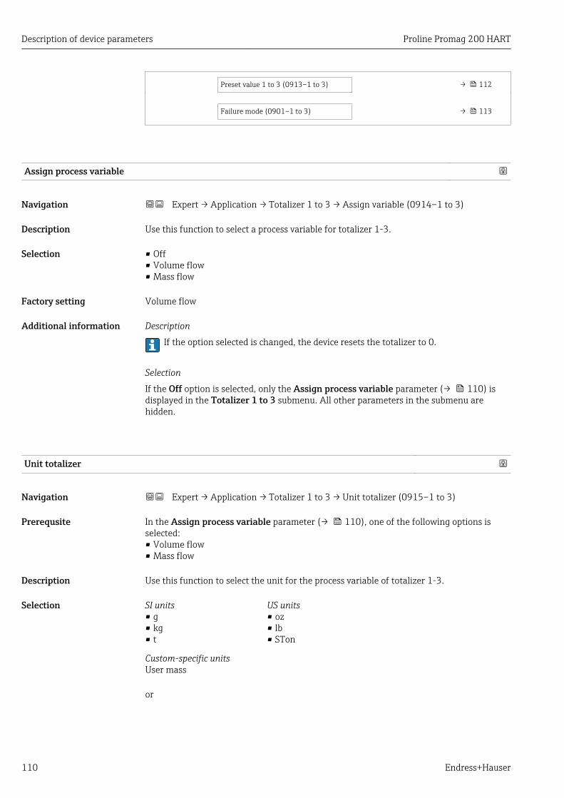
Description of device parameters Proline Promag 200 HART
110 Endress+Hauser
Preset value 1 to 3 (0913–1 to 3) → 112
Failure mode (0901–1 to 3) → 113
Assign process variable
Navigation Expert → Application → Totalizer 1 to 3 → Assign variable (0914–1 to 3)
Description Use this function to select a process variable for totalizer 1-3.
Selection • Off• Volume flow• Mass flow
Factory setting Volume flow
Additional information Description
If the option selected is changed, the device resets the totalizer to 0.
Selection
If the Off option is selected, only the Assign process variable parameter (→ 110) isdisplayed in the Totalizer 1 to 3 submenu. All other parameters in the submenu arehidden.
Unit totalizer
Navigation Expert → Application → Totalizer 1 to 3 → Unit totalizer (0915–1 to 3)
Prerequsite In the Assign process variable parameter (→ 110), one of the following options isselected:• Volume flow• Mass flow
Description Use this function to select the unit for the process variable of totalizer 1-3.
Selection SI units• g• kg• t
US units• oz• lb• STon
Custom-specific unitsUser mass
or

Proline Promag 200 HART Description of device parameters
Endress+Hauser 111
SI units• cm³• dm³• m³• ml• l• hl• Ml Mega
US units• af• ft³• fl oz (us)• gal (us)• kgal (us)• Mgal (us)• bbl (us;liq.)• bbl (us;beer)• bbl (us;oil)• bbl (us;tank)
Imperial units• gal (imp)• Mgal (imp)• bbl (imp;beer)• bbl (imp;oil)
Custom-specific unitsUser vol.
Factory setting Country-specific:• l• gal (us)
Additional information Description
The unit is selected separately for each totalizer. It is independent of the optionselected in the System units submenu (→ 45).
Selection
The selection depends on the process variable selected in the Assign process variableparameter (→ 110).
Totalizer operation mode
Navigation Expert → Application → Totalizer 1 to 3 → Operation mode (0908–1 to 3)
Prerequsite In the Assign process variable parameter (→ 110), one of the following options isselected:• Volume flow• Mass flow
Description Use this function to select how the totalizer summates the flow.
Selection • Net flow total• Forward flow total• Reverse flow total
Factory setting Net flow total
Additional information Selection
• Net flow totalPositive and negative flow values are totalized and balanced against one another. Netflow is registered in the flow direction.
• Forward flow totalOnly the flow in the forward flow direction is totalized.
• Reverse flow totalOnly the flow against the forward flow direction is totalized (= reverse flow total).

Description of device parameters Proline Promag 200 HART
112 Endress+Hauser
Control Totalizer 1 to 3
Navigation Expert → Application → Totalizer 1 to 3 → Control Tot. 1 to 3 (0912–1 to 3)
Prerequsite In the Assign process variable parameter (→ 110), one of the following options isselected:• Volume flow• Mass flow
Description Use this function to select the control of totalizer value 1-3.
Selection • Totalize• Reset + hold• Preset + hold• Reset + totalize• Preset + totalize
Factory setting Totalize
Additional information Selection
• TotalizeThe totalizer is started or continues totalizing with the current counter reading.
• Reset + holdThe totaling process is stopped and the totalizer is reset to 0.
• Preset + holdThe totaling process is stopped and the totalizer is set to its defined start value from thePreset value parameter (→ 112).
• Reset + totalizeThe totalizer is reset to 0 and the totaling process is restarted.
• Preset + totalizeThe totalizer is set to the defined start value in the Preset value parameter(→ 112)and the totaling process is restarted.
Preset value 1 to 3
Navigation Expert → Application → Totalizer 1 to 3 → Preset value 1 to 3 (0913–1 to 3)
Prerequsite In the Assign process variable parameter (→ 110), one of the following options isselected:• Volume flow• Mass flow
Description Use this function to enter a start value for totalizer 1-3.
User entry Signed floating-point number
Factory setting Country-specific:• 0 l• 0 gal (us)

Proline Promag 200 HART Description of device parameters
Endress+Hauser 113
Additional information User entry
The unit of the selected process variable is specified for the totalizer in the Unittotalizer parameter (→ 110).
Example
This configuration is suitable for applications such as iterative filling processes with a fixedbatch quantity.
Failure mode
Navigation Expert → Application → Totalizer 1 to 3 → Failure mode (0901–1 to 3)
Prerequsite In the Assign process variable parameter (→ 110), one of the following options isselected:• Volume flow• Mass flow
Description Use this function to select how a totalizer behaves in an alarm condition.
Selection • Stop• Actual value• Last valid value
Factory setting Stop
Additional information Description
This setting does not affect the error response mode of other totalizers and theoutputs. This is specified in separate parameters.
Selection
• StopTotalizing is stopped in an alarm condition.
• Actual valueThe totalizer continues to count based on the actual measured value; the error isignored.
• Last valid valueThe totalizer continues to count based on the last valid measured value before the erroroccurred.
3.6 "Diagnostics" submenu
Navigation Expert → Diagnostics
‣ Diagnostics
Actual diagnostics (0691) → 114

Description of device parameters Proline Promag 200 HART
114 Endress+Hauser
Previous diagnostics (0690) → 115
Operating time from restart (0653) → 116
Operating time (0652) → 116
‣ Diagnostic list → 116
‣ Event logbook → 120
‣ Device information → 122
‣ Data logging → 126
‣ Min/max values → 131
‣ Heartbeat → 135
‣ Simulation → 136
Actual diagnostics
Navigation Expert → Diagnostics → Actual diagnos. (0691)
Prerequsite A diagnostic event has occurred.
Description Use this function to display the current diagnostics message. If two or more messagesoccur simultaneously, the message with the highest priority is shown on the display.
User interface Symbol for diagnostic behavior, diagnostic code and short message.
Additional information User interface
Additional pending diagnostic messages can be viewed in the Diagnostic listsubmenu (→ 116).
Information on what is causing the diagnostic message, and remedy measures, can beviewed by pressing the -button.
Example
For the display format:S442 Frequency output

Proline Promag 200 HART Description of device parameters
Endress+Hauser 115
Timestamp
Navigation Expert → Diagnostics → Timestamp (0667)
Description Displays the operating time at which the current diagnostic message occurred.
User interface Days (d), hours (h), minutes (m) and seconds (s)
Additional information User interface
The diagnostic message can be viewed via the Actual diagnostics parameter(→ 114).
Example
For the display format:24d12h13m00s
Previous diagnostics
Navigation Expert → Diagnostics → Prev.diagnostics (0690)
Prerequsite Two diagnostic events have already occurred.
Description Use this function to display the diagnostic message last displayed before the currentmessage.
User interface Symbol for diagnostic behavior, diagnostic code and short message.
Additional information User interface
Information on what is causing the diagnostic message, and remedy measures, can beviewed by pressing the -button.
Example
For the display format:S442 Frequency output
Timestamp
Navigation Expert → Diagnostics → Timestamp (0672)
Description Displays the operating time of the last diagnostic message that occurred before the currentmessage.
User interface Days (d), hours (h), minutes (m) and seconds (s)
Additional information User interface
The diagnostic message can be viewed via the Previous diagnostics parameter(→ 115).

Description of device parameters Proline Promag 200 HART
116 Endress+Hauser
Example
For the display format:24d12h13m00s
Operating time from restart
Navigation Expert → Diagnostics → Time fr. restart (0653)
Description Use this function to display the time the device has been in operation since the last devicerestart.
User interface Days (d), hours (h), minutes (m) and seconds (s)
Operating time
Navigation Expert → Diagnostics → Operating time (0652)
Description Use this function to display the length of time the device has been in operation.
User interface Days (d), hours (h), minutes (m) and seconds (s)
Additional information User interface
The maximum number of days is 9999, which is equivalent to 27 years.
3.6.1 "Diagnostic list" submenu
Navigation Expert → Diagnostics → Diagnostic list
‣ Diagnostic list
Diagnostics 1 (0692) → 117
Diagnostics 2 (0693) → 117
Diagnostics 3 (0694) → 118
Diagnostics 4 (0695) → 119
Diagnostics 5 (0696) → 119

Proline Promag 200 HART Description of device parameters
Endress+Hauser 117
Diagnostics 1
Navigation Expert → Diagnostics → Diagnostic list → Diagnostics 1 (0692)
Description Use this function to display the current diagnostics message with the highest priority.
User interface Symbol for diagnostic behavior, diagnostic code and short message.
Additional information Examples
For the display format:• S442 Frequency output• F276 I/O module failure
Timestamp
Navigation Expert → Diagnostics → Diagnostic list → Timestamp (0683)
Description Displays the operating time at which the diagnostic message occurred.
User interface Days (d), hours (h), minutes (m) and seconds (s)
Additional information User interface
The diagnostic message can be viewed via the Diagnostics 1 parameter (→ 117).
Example
For the display format:24d12h13m00s
Diagnostics 2
Navigation Expert → Diagnostics → Diagnostic list → Diagnostics 2 (0693)
Description Use this function to display the current diagnostics message with the second-highestpriority.
User interface Symbol for diagnostic behavior, diagnostic code and short message.
Additional information Examples
For the display format:• S442 Frequency output• F276 I/O module failure

Description of device parameters Proline Promag 200 HART
118 Endress+Hauser
Timestamp
Navigation Expert → Diagnostics → Diagnostic list → Timestamp (0684)
Description Displays the operating time at which the diagnostic message occurred.
User interface Days (d), hours (h), minutes (m) and seconds (s)
Additional information User interface
The diagnostic message can be viewed via the Diagnostics 2 parameter (→ 117).
Example
For the display format:24d12h13m00s
Diagnostics 3
Navigation Expert → Diagnostics → Diagnostic list → Diagnostics 3 (0694)
Description Use this function to display the current diagnostics message with the third-highestpriority.
User interface Symbol for diagnostic behavior, diagnostic code and short message.
Additional information Examples
For the display format:• S442 Frequency output• F276 I/O module failure
Timestamp
Navigation Expert → Diagnostics → Diagnostic list → Timestamp (0685)
Description Displays the operating time at which the diagnostic message occurred.
User interface Days (d), hours (h), minutes (m) and seconds (s)
Additional information User interface
The diagnostic message can be viewed via the Diagnostics 3 parameter (→ 118).
Example
For the display format:24d12h13m00s

Proline Promag 200 HART Description of device parameters
Endress+Hauser 119
Diagnostics 4
Navigation Expert → Diagnostics → Diagnostic list → Diagnostics 4 (0695)
Description Use this function to display the current diagnostics message with the fourth-highestpriority.
User interface Symbol for diagnostic behavior, diagnostic code and short message.
Additional information Examples
For the display format:• S442 Frequency output• F276 I/O module failure
Timestamp
Navigation Expert → Diagnostics → Diagnostic list → Timestamp (0686)
Description Displays the operating time at which the diagnostic message occurred.
User interface Days (d), hours (h), minutes (m) and seconds (s)
Additional information User interface
The diagnostic message can be viewed via the Diagnostics 4 parameter (→ 119).
Example
For the display format:24d12h13m00s
Diagnostics 5
Navigation Expert → Diagnostics → Diagnostic list → Diagnostics 5 (0696)
Description Use this function to display the current diagnostics message with the fifth-highest priority.
User interface Symbol for diagnostic behavior, diagnostic code and short message.
Additional information Examples
For the display format:• S442 Frequency output• F276 I/O module failure

Description of device parameters Proline Promag 200 HART
120 Endress+Hauser
Timestamp
Navigation Expert → Diagnostics → Diagnostic list → Timestamp (0687)
Description Displays the operating time at which the diagnostic message occurred.
User interface Days (d), hours (h), minutes (m) and seconds (s)
Additional information User interface
The diagnostic message can be viewed via the Diagnostics 5 parameter (→ 119).
Example
For the display format:24d12h13m00s
3.6.2 "Event logbook" submenu
Navigation Expert → Diagnostics → Event logbook
‣ Event logbook
Filter options (0705) → 120
‣ Event list → 121
Filter options
Navigation Expert → Diagnostics → Event logbook → Filter options (0705)
Description Use this function to select the category whose event messages are displayed in the eventslist.
Selection • All• Failure (F)• Function check (C)• Out of specification (S)• Maintenance required (M)• Information (I)
Factory setting All

Proline Promag 200 HART Description of device parameters
Endress+Hauser 121
Additional information Description
The status signals are categorized in accordance with VDI/VDE 2650 and NAMURRecommendation NE 107:• F = Failure• C = Function Check• S = Out of Specification• M = Maintenance Required
"Event list" submenu
Navigation Expert → Diagnostics → Event logbook → Event list
▸ Event list
Event list → 121
Event list
Navigation Expert → Diagnostics → Event logbook → Event list
Description Use this function to display the history of event messages that have occurred in thecategory selected in the Filter options parameter (→ 120).
User interface • For a "Category I" event messageInformation event, short message, symbol for event recording and operating time whenerror occurred
• For a "Category F, C, S, M" event message (status signal)Diagnostics code, short message, symbol for event recording and operating time whenerror occurred
Additional information Description
A maximum of 20 event messages are displayed in chronological order. If the advancedHistoROM function is enabled in the device, the event list can contain up to 100 entries.
The following symbols indicate whether an event has occurred or has ended:• : Occurrence of the event• : End of the event
Examples
For the display format:• I1091 Configuration modified
24d12h13m00s• S442 Frequency output
01d04h12min30s
Additional information, such as remedial measures, can be called up via the key.

Description of device parameters Proline Promag 200 HART
122 Endress+Hauser
HistoROM
A HistoROM is a "non-volatile" device memory in the form of an EEPROM.
To order the HistoROM advanced capabilities application package, see the"Accessories" section of the "Technical Information" document.
3.6.3 "Device information" submenu
Navigation Expert → Diagnostics → Device info
‣ Device information
Device tag (0011) → 122
Serial number (0009) → 123
Firmware version (0010) → 123
Device name (0013) → 123
Order code (0008) → 124
Extended order code 1 (0023) → 124
Extended order code 2 (0021) → 124
Extended order code 3 (0022) → 125
Configuration counter (0233) → 125
ENP version (0012) → 125
Device tag
Navigation Expert → Diagnostics → Device info → Device tag (0011)
Description Use this function to display a unique name for the measuring point so it can be identifiedquickly within the plant. The name is displayed in the header.
User interface Max. 32 characters such as letters, numbers or special characters (e.g. @, %, /)
Factory setting Promag

Proline Promag 200 HART Description of device parameters
Endress+Hauser 123
Additional information User interface
1 XXXXXXXXX
A0013375
7 Header text
The number of characters displayed depends on the characters used.
Serial number
Navigation Expert → Diagnostics → Device info → Serial number (0009)
Description Use this function to view the serial number of the measuring device. It can also be foundon the nameplate of the sensor and transmitter.
User interface Max. 11-digit character string comprising letters and numbers.
Additional information Description
Uses of the serial number• To identify the measuring device quickly, e.g. when contacting Endress+Hauser.• To obtain specific information on the measuring device using the Device Viewer:
www.endress.com/deviceviewer
Firmware version
Navigation Expert → Diagnostics → Device info → Firmware version (0010)
Description Use this function to view the device firmware version installed.
User interface Character string with the following format:xx.yy.zz
Factory setting 01.01.zz
Device name
Navigation Expert → Diagnostics → Device info → Device name (0013)
Description Use this function to view the name of the transmitter. It can also be found on thenameplate of the transmitter.

Description of device parameters Proline Promag 200 HART
124 Endress+Hauser
User interface Character string composed of letters, numbers and certain punctuation marks.
Factory setting Promag
Order code
Navigation Expert → Diagnostics → Device info → Order code (0008)
Description Use this function to display the device order code.
User interface Character string composed of letters, numbers and certain punctuation marks
Additional information Description
The order code can be found on the nameplate of the sensor and transmitter in the"Order code" field.
The order code is generated from the extended order code, which defines all the devicefeatures of the product structure. In contrast, the device features cannot be read directlyfrom the order code.
Uses of the order code• To order an identical spare device.• To identify the device quickly and easily, e.g. when contacting Endress+Hauser.
Extended order code 1
Navigation Expert → Diagnostics → Device info → Ext. order cd. 1 (0023)
Description For displaying the first part of the extended order code.
On account of length restrictions, the extended order code is split into a maximum of 3parameters.
User interface Character string
Additional information Description
The extended order code indicates the version of all the features of the product structurefor the measuring device and thus uniquely identifies the measuring device.
The extended order code can also be found on the nameplate of the sensor andtransmitter in the "Ext. ord. cd." field.
Extended order code 2
Navigation Expert → Diagnostics → Device info → Ext. order cd. 2 (0021)
Description For displaying the second part of the extended order code.

Proline Promag 200 HART Description of device parameters
Endress+Hauser 125
User interface Character string
Additional information For additional information, see Extended order code 1 parameter (→ 124)
Extended order code 3
Navigation Expert → Diagnostics → Device info → Ext. order cd. 3 (0022)
Description For displaying the third part of the extended order code.
User interface Character string
Additional information For additional information, see Extended order code 1 parameter (→ 124)
Configuration counter
Navigation Expert → Diagnostics → Device info → Config. counter (0233)
Description Displays the number of parameter modifications for the device. When the user changes aparameter setting, this counter is incremented.
User interface 0 to 65 535
Factory setting 0
ENP version
Navigation Expert → Diagnostics → Device info → ENP version (0012)
Description Displays the version of the electronic nameplate.
Factory setting 2.02.00
Additional information Description
This electronic nameplate stores a data record for device identification that includes moredata than the nameplates attached to the outside of the device.

Description of device parameters Proline Promag 200 HART
126 Endress+Hauser
3.6.4 "Data logging" submenu
Navigation Expert → Diagnostics → Data logging
‣ Data logging
Assign channel 1 (0851) → 126
Assign channel 2 (0852) → 127
Assign channel 3 (0853) → 127
Assign channel 4 (0854) → 128
Logging interval (0856) → 128
Clear logging data (0855) → 129
‣ Display channel 1 → 129
‣ Display channel 2 → 130
‣ Display channel 3 → 130
‣ Display channel 4 → 131
Assign channel 1
Navigation Expert → Diagnostics → Data logging → Assign chan. 1 (0851)
Expert → Diagnostics → Data logging → Assign chan. 1 (0851)
Prerequsite The Extended HistoROM application package is available.
The software options currently enabled are displayed in the Software optionoverview parameter (→ 38).
Description Options for the assignment of a process variable to the data logging channel.
Selection • Off• Volume flow• Mass flow• Electronic temperature• Current output 1• Current difference potential
Factory setting Off

Proline Promag 200 HART Description of device parameters
Endress+Hauser 127
Additional information Description
A total of 1000 measured values can be logged. This means:• 1000 data points if 1 logging channel is used• 500 data points if 2 logging channels are used• 333 data points if 3 logging channels are used• 250 data points if 4 logging channels are used
Once the maximum number of data points is reached, the oldest data points in the data logare cyclically overwritten in such a way that the last 1000, 500, 333 or 250 measuredvalues are always in the log (ring memory principle).
The log contents are cleared if the option selected is changed.
Assign channel 2
Navigation Expert → Diagnostics → Data logging → Assign chan. 2 (0852)
Expert → Diagnostics → Data logging → Assign chan. 2 (0852)
Prerequsite The Extended HistoROM application package is available.
The software options currently enabled are displayed in the Software optionoverview parameter (→ 38).
Description Options for the assignment of a process variable to the data logging channel.
Selection Picklist, see Assign channel 1 parameter (→ 126)
Factory setting Off
Assign channel 3
Navigation Expert → Diagnostics → Data logging → Assign chan. 3 (0853)
Expert → Diagnostics → Data logging → Assign chan. 3 (0853)
Prerequsite The Extended HistoROM application package is available.
The software options currently enabled are displayed in the Software optionoverview parameter (→ 38).
Description Options for the assignment of a process variable to the data logging channel.
Selection Picklist, see Assign channel 1 parameter (→ 126)
Factory setting Off

Description of device parameters Proline Promag 200 HART
128 Endress+Hauser
Assign channel 4
Navigation Expert → Diagnostics → Data logging → Assign chan. 4 (0854)
Expert → Diagnostics → Data logging → Assign chan. 4 (0854)
Prerequsite The Extended HistoROM application package is available.
The software options currently enabled are displayed in the Software optionoverview parameter (→ 38).
Description Options for the assignment of a process variable to the data logging channel.
Selection Picklist, see Assign channel 1 parameter (→ 126)
Factory setting Off
Logging interval
Navigation Expert → Diagnostics → Data logging → Logging interval (0856)
Expert → Diagnostics → Data logging → Logging interval (0856)
Prerequsite The Extended HistoROM application package is available.
The software options currently enabled are displayed in the Software optionoverview parameter (→ 38).
Description Use this function to enter the logging interval tlog for data logging.
User entry 1.0 to 3 600.0 s
Factory setting 10.0 s
Additional information Description
This defines the interval between the individual data points in the data log, and thus themaximum loggable process time Tlog:• If 1 logging channel is used: Tlog = 1000 × tlog• If 2 logging channels are used: Tlog = 500 × tlog• If 3 logging channels are used: Tlog = 333 × tlog• If 4 logging channels are used: Tlog = 250 × tlog
Once this time elapses, the oldest data points in the data log are cyclically overwritten suchthat a time of Tlog always remains in the memory (ring memory principle).
The log contents are cleared if the length of the logging interval is changed.
Example
If 1 logging channel is used:• Tlog = 1000 × 1 s = 1 000 s ≈15 min• Tlog = 1000 × 10 s = 10 000 s ≈ 3 h• Tlog = 1000 × 80 s = 80 000 s ≈ 1 d• Tlog = 1000 × 3 600 s = 3 600 000 s ≈ 41 d

Proline Promag 200 HART Description of device parameters
Endress+Hauser 129
Clear logging data
Navigation Expert → Diagnostics → Data logging → Clear logging (0855)
Expert → Diagnostics → Data logging → Clear logging (0855)
Prerequsite The Extended HistoROM application package is available.
The software options currently enabled are displayed in the Software optionoverview parameter (→ 38).
Description Option to clear the entire logging data.
Selection • Cancel• Clear data
Factory setting Cancel
Additional information Selection
• CancelThe data is not cleared. All the data is retained.
• Clear dataThe logging data is cleared. The logging process starts from the beginning.
"Display channel 1" submenu
Navigation Expert → Diagnostics → Data logging → Displ.channel 1
▸ Display channel 1
Display channel 1 → 129
Display channel 1
Navigation Expert → Diagnostics → Data logging → Displ.channel 1
Prerequsite In the Assign channel 1 parameter (→ 126), one of the following options is selected:• Volume flow• Mass flow• Electronic temperature• Current output 1• Current difference potential
Description Use this function to view the measured value trend for the logging channel in the form of achart.

Description of device parameters Proline Promag 200 HART
130 Endress+Hauser
Additional information Description
A0016222
• x-axis: depending on the number of channels selected displays 250 to 1000 measuredvalues of a process variable.
• y-axis: displays the approximate measured value span and constantly adapts this to theongoing measurement.
"Display channel 2" submenu
Navigation Expert → Diagnostics → Data logging → Displ.channel 2
▸ Display channel 2
Display channel 2 → 130
Display channel 2
Navigation Expert → Diagnostics → Data logging → Displ.channel 2
Prerequsite In the Assign channel 2 parameter, one of the following options is selected:• Volume flow• Mass flow• Electronic temperature• Current output 1• Current difference potential
Description See the Display channel 1 parameter → 129
"Display channel 3" submenu
Navigation Expert → Diagnostics → Data logging → Displ.channel 3
▸ Display channel 3
Display channel 3 → 131

Proline Promag 200 HART Description of device parameters
Endress+Hauser 131
Display channel 3
Navigation Expert → Diagnostics → Data logging → Displ.channel 3
Prerequsite In the Assign channel 3 parameter, one of the following options is selected:• Volume flow• Mass flow• Electronic temperature• Current output 1• Current difference potential
Description See the Display channel 1 parameter → 129
"Display channel 4" submenu
Navigation Expert → Diagnostics → Data logging → Displ.channel 4
▸ Display channel 4
Display channel 4 → 131
Display channel 4
Navigation Expert → Diagnostics → Data logging → Displ.channel 4
Prerequsite In the Assign channel 4 parameter, one of the following options is selected:• Volume flow• Mass flow• Electronic temperature• Current output 1• Current difference potential
Description See the Display channel 1 parameter → 129
3.6.5 "Min/max values" submenu
Navigation Expert → Diagnostics → Min/max val.
‣ Min/max values
Reset min/max values (6541) → 132

Description of device parameters Proline Promag 200 HART
132 Endress+Hauser
‣ Terminal voltage → 132
‣ Main electronic temperature → 133
‣ IO module temperature → 134
Reset min/max values
Navigation Expert → Diagnostics → Min/max val. → Reset min/max (6541)
Description Use this function to select measured variables whose minimum, maximum and averagemeasured values are to be reset.
Selection • Cancel• Terminal voltage• IO module temperature
Factory setting Cancel
"Terminal voltage" submenu
Navigation Expert → Diagnostics → Min/max val. → Terminal volt.
‣ Terminal voltage
Minimum value (0689) → 132
Maximum value (0663) → 133
Average value (0698) → 133
Minimum value
Navigation Expert → Diagnostics → Min/max val. → Terminal volt. → Minimum value (0689)
Description Use this function to display the smallest previously measured terminal voltage value inVolts.
User interface 0.0 to 50.0 V

Proline Promag 200 HART Description of device parameters
Endress+Hauser 133
Maximum value
Navigation Expert → Diagnostics → Min/max val. → Terminal volt. → Maximum value (0663)
Description Use this function to view the largest previously measured terminal voltage value in Volts.
User interface 0.0 to 50.0 V
Average value
Navigation Expert → Diagnostics → Min/max val. → Terminal volt. → Average value (0698)
Description Use this function to view the average of all previously measured terminal voltage values inVolts.
User interface Signed floating-point number
"Main electronic temperature" submenu
Navigation Expert → Diagnostics → Min/max val. → Main elect.temp.
‣ Main electronic temperature
Minimum value (6547) → 133
Maximum value (6545) → 134
Minimum value
Navigation Expert → Diagnostics → Min/max val. → Main elect.temp. → Minimum value (6547)
Description Use this function to view the lowest previously measured temperature value of the mainelectronics module.
User interface Signed floating-point number
Additional information Dependency
The unit is taken from the Temperature unit parameter (→ 49).

Description of device parameters Proline Promag 200 HART
134 Endress+Hauser
Maximum value
Navigation Expert → Diagnostics → Min/max val. → Main elect.temp. → Maximum value(6545)
Description Use this function to view the highest previously measured temperature value of the mainelectronics module.
User interface Signed floating-point number
Additional information Dependency
The unit is taken from the Temperature unit parameter (→ 49).
"IO module temperature" submenu
Navigation Expert → Diagnostics → Min/max val. → IO module temp.
‣ IO module temperature
Minimum value (0688) → 134
Maximum value (0665) → 135
Average value (0697) → 135
Minimum value
Navigation Expert → Diagnostics → Min/max val. → IO module temp. → Minimum value (0688)
Description Use this function to view the lowest previously measured temperature value of the I/Oelectronics module.
User interface Signed floating-point number
Additional information Dependency
The unit is taken from the Temperature unit parameter (→ 49).

Proline Promag 200 HART Description of device parameters
Endress+Hauser 135
Maximum value
Navigation Expert → Diagnostics → Min/max val. → IO module temp. → Maximum value (0665)
Description Use this function to view the highest previously measured temperature value of the I/Oelectronics module.
User interface Signed floating-point number
Additional information Dependency
The unit is taken from the Temperature unit parameter (→ 49).
Average value
Navigation Expert → Diagnostics → Min/max val. → IO module temp. → Average value (0697)
Description Use this function to view the average value of all previously measured temperature valuesof the I/O electronics module.
User interface –1 273.15 to 726.85 °C
Additional information Dependency
The unit is taken from the Temperature unit parameter (→ 49).
3.6.6 "Heartbeat" submenuFor detailed information on the parameter descriptions of the Heartbeat Verificationapplication package, see the Special Documentation for the device
Navigation Expert → Diagnostics → Heartbeat
‣ Heartbeat
‣ Heartbeat base settings
‣ Performing verification
‣ Verification results

Description of device parameters Proline Promag 200 HART
136 Endress+Hauser
3.6.7 "Simulation" submenu
Navigation Expert → Diagnostics → Simulation
‣ Simulation
Assign simulation process variable(1810)
→ 136
Process variable value (1811) → 137
Simulation current output 1 (0354–1) → 137
Value current output 1 (0355–1) → 138
Frequency output simulation (0472) → 138
Frequency value (0473) → 138
Pulse output simulation (0458) → 139
Pulse value (0459) → 139
Switch output simulation (0462) → 140
Switch status (0463) → 140
Simulation device alarm (0654) → 141
Diagnostic event category (0738) → 141
Diagnostic event simulation (0737) → 141
Assign simulation process variable
Navigation Expert → Diagnostics → Simulation → Assign proc.var. (1810)
Description Use this function to select a process variable for the simulation process that is activated.The display alternates between the measured value and a diagnostic message of the"Function check" category (C) while simulation is in progress.
Selection • Off• Volume flow• Mass flow
Factory setting Off

Proline Promag 200 HART Description of device parameters
Endress+Hauser 137
Additional information Description
The simulation value of the selected process variable is defined in the Processvariable value parameter (→ 137).
Process variable value
Navigation Expert → Diagnostics → Simulation → Proc. var. value (1811)
Prerequsite In the Assign simulation process variable parameter (→ 136), one of the followingoptions is selected:• Volume flow• Mass flow
Description Use this function to enter a simulation value for the selected process variable. Subsequentmeasured value processing and the signal output use this simulation value. In this way,users can verify whether the measuring device has been configured correctly.
User entry Depends on the process variable selected
Factory setting 0
Additional information User entry
The unit of the displayed measured value is taken from the System units submenu(→ 45).
Simulation current output 1
Navigation Expert → Diagnostics → Simulation → Sim.curr.out. 1 (0354–1)
Description Use this function to switch simulation of the current output on and off. The displayalternates between the measured value and a diagnostic message of the "Function check"category (C) while simulation is in progress.
Selection • Off• On
Factory setting Off
Additional information Description
The desired simulation value is defined in the Value current output 1 parameter(→ 138).
Selection
• OffCurrent simulation is switched off. The device is in normal measuring mode or anotherprocess variable is being simulated.
• OnCurrent simulation is active.

Description of device parameters Proline Promag 200 HART
138 Endress+Hauser
Value current output 1
Navigation Expert → Diagnostics → Simulation → Value curr.out 1 (0355–1)
Prerequsite The On option is selected in the Simulation current output 1 parameter (→ 137).
Description Use this function to enter a current value for the simulation. In this way, users can verifythe correct adjustment of the current output and the correct function of downstreamswitching units.
User entry 3.59 to 22.5 mA
Frequency output simulation
Navigation Expert → Diagnostics → Simulation → Freq.outp.sim. (0472)
Prerequsite The Frequency option is selected in the Operating mode parameter (→ 79).
Description Use this function to switch simulation of the frequency output on and off. The displayalternates between the measured value and a diagnostic message of the "Function check"category (C) while simulation is in progress.
Selection • Off• On
Factory setting Off
Additional information Description
The desired simulation value is defined in the Frequency value parameter(→ 138).
Selection
• OffCurrent simulation is switched off. The device is in normal measuring mode or anotherprocess variable is being simulated.
• OnCurrent simulation is active.
Frequency value
Navigation Expert → Diagnostics → Simulation → Freq. value (0473)
Prerequsite The On option is selected in the Frequency output simulation parameter (→ 138).
Description Use this function to enter a frequency value for the simulation. In this way, users can verifythe correct adjustment of the frequency output and the correct function of downstreamswitching units.

Proline Promag 200 HART Description of device parameters
Endress+Hauser 139
User entry 0.0 to 1 250.0 Hz
Factory setting 0.0 Hz
Pulse output simulation
Navigation Expert → Diagnostics → Simulation → Puls.outp.sim. (0458)
Prerequsite The Pulse option is selected in the Operating mode parameter (→ 79).
Description Use this function to switch simulation of the pulse output on and off. The displayalternates between the measured value and a diagnostic message of the "Function check"category (C) while simulation is in progress.
Selection • Off• Fixed value• Down-counting value
Factory setting Off
Additional information Description
The desired simulation value is defined in the Pulse value parameter (→ 139).
Selection
• OffPulse simulation is switched off. The device is in normal measuring mode or anotherprocess variable is being simulated.
• Fixed valuePulses are continuously output with the pulse width specified in the Pulse widthparameter (→ 80).
• Down-counting valueThe pulses specified in the Pulse value parameter (→ 139) are output.
Pulse value
Navigation Expert → Diagnostics → Simulation → Pulse value (0459)
Prerequsite The Down-counting value option is selected in the Pulse output simulation parameter(→ 139).
Description Use this function to enter a pulse value for the simulation. In this way, users can verify thecorrect adjustment of the pulse output and the correct function of downstream switchingunits.
User entry 0 to 65 535
Factory setting 0

Description of device parameters Proline Promag 200 HART
140 Endress+Hauser
Switch output simulation
Navigation Expert → Diagnostics → Simulation → Switch sim. (0462)
Prerequsite The Switch option is selected in the Operating mode parameter (→ 79).
Description Use this function to switch simulation of the switch output on and off. The displayalternates between the measured value and a diagnostic message of the "Function check"category (C) while simulation is in progress.
Selection • Off• On
Factory setting Off
Additional information Description
The desired simulation value is defined in the Switch status parameter (→ 140).
Selection
• OffSwitch simulation is switched off. The device is in normal measuring mode or anotherprocess variable is being simulated.
• OnSwitch simulation is active.
Switch status
Navigation Expert → Diagnostics → Simulation → Switch status (0463)
Prerequsite The On option is selected in the Switch output simulation parameter (→ 140).
Description Use this function to select a switch value for the simulation. In this way, users can verifythe correct adjustment of the switch output and the correct function of downstreamswitching units.
Selection • Open• Closed
Factory setting Open
Additional information Options
• OpenSwitch simulation is switched off. The device is in normal measuring mode or anotherprocess variable is being simulated.
• ClosedSwitch simulation is active.

Proline Promag 200 HART Description of device parameters
Endress+Hauser 141
Simulation device alarm
Navigation Expert → Diagnostics → Simulation → Sim. alarm (0654)
Description Use this function to switch the device alarm on and off. In this way, users can verify thecorrect adjustment of the current output and the correct function of downstream switchingunits. The display alternates between the measured value and a diagnostic message of the"Function check" category (C) while simulation is in progress.
Selection • Off• On
Factory setting Off
Diagnostic event category
Navigation Expert → Diagnostics → Simulation → Event category (0738)
Description Use this function to select the category of the diagnostic events that are displayed for thesimulation in the Diagnostic event simulation parameter (→ 141).
Selection • Sensor• Electronics• Configuration• Process
Factory setting Process
Diagnostic event simulation
Navigation Expert → Diagnostics → Simulation → Diag. event sim. (0737)
Description Use this function to select a diagnostic event for the simulation process that is activated.
Selection • Off• Diagnostic event picklist (depends on the category selected)
Factory setting Off
Additional information Description
For the simulation, you can choose from the diagnostic events of the category selectedin the Diagnostic event category parameter (→ 141).

Country-specific factory settings Proline Promag 200 HART
142 Endress+Hauser
4 Country-specific factory settings
4.1 SI unitsNot valid for USA and Canada.
4.1.1 System units
Mass kg
Mass flow kg/h
Volume m³
Volume flow l/h
Density kg/l
Temperature °C
4.1.2 Full scale valuesThe factory settings applie to the following parameters:• 20 mA value (full scale value of the current output)• 100% bar graph value 1• 100% bar graph value 3
Nominal diameter[mm]
Full scale value current output(v ~ 2.5 m/s)
[dm³/min]
2 0.5
4 2
8 8
15 25
25 75
32 125
40 200
50 300
65 500
80 750
100 1 200
125 1 850
150 150 m3/h
200 300 m3/h
4.1.3 Output current span
Current output 1 4 to 20 mA NAMUR
4.1.4 On value low flow cut offThe switch-on point depends on the type of medium and the nominal diameter.

Proline Promag 200 HART Country-specific factory settings
Endress+Hauser 143
Nominal diameter[mm]
On value low flow cut off(v ~ 0.04 m/s)
[m³/h]
2 0.01
4 0.05
8 0.1
15 0.5
25 1
32 2
40 3
50 5
65 8
80 12
100 20
125 30
150 2.5
200 5
4.2 US unitsOnly valid for USA and Canada.
4.2.1 System units
Mass lb
Mass flow lb/min
Volume gal (us)
Volume flow gal/min (us)
Density lb/ft³
Temperature °F
4.2.2 Full scale valuesThe factory settings applie to the following parameters:• 20 mA value (full scale value of the current output)• 100% bar graph value 1• 100% bar graph value 3
Nominal diameter[in]
Full scale value current output(v ~ 2.5 m/s)
[gal/min]
¹/₁₂ 0.1
¹/₈ 0.5
³/₈ 2
½ 6
1 18
1½ 50

Country-specific factory settings Proline Promag 200 HART
144 Endress+Hauser
Nominal diameter[in]
Full scale value current output(v ~ 2.5 m/s)
[gal/min]
2 75
3 200
4 300
6 600
8 1 200
4.2.3 Output current span
Current output 1 4 to 20 mA US
4.2.4 On value low flow cut offThe switch-on point depends on the type of medium and the nominal diameter.
Nominal diameter[in]
On value low flow cut off(v ~ 0.04 m/s)
[gal/min]
¹/₁₂ 0.002
¹/₈ 0.008
³/₈ 0.025
½ 0.1
1 0.25
1½ 0.75
2 1.25
3 2.5
4 4
6 12
8 15

Proline Promag 200 HART Explanation of abbreviated units
Endress+Hauser 145
5 Explanation of abbreviated units
5.1 SI units
Process variable Units Explanation
Density g/cm3, g/m3 Gram/volume unit
kg/dm³, kg/l, kg/m³ Kilogram/volume unit
SD4°C, SD15°C, SD20°C Specific density: The specific density is the ratio of thedensity of the fluid to the density of water at a watertemperature of 4 °C (39 °F), 15 °C (59 °F), 20 °C (68 °F).
SG4°C, SG15°C, SG20°C Specific gravity: The specific gravity is the ratio of thedensity of the fluid to the density of water at a watertemperature of 4 °C (39 °F), 15 °C (59 °F), 20 °C (68 °F).
Mass g, kg, t Gram, kilogram, metric ton
Mass flow g/s, g/min, g/h, g/d Gram/time unit
kg/s, kg/min, kg/h, kg/d Kilogram/time unit
t/s, t/min, t/h, t/d Metric ton/time unit
Temperature °C , °F, K, °R Celsius, Fahrenheit, Kelvin, Rankine
Volume cm³, dm³, m³ Cubic centimeter, cubic decimeter, cubic meter,
ml, l, hl, Ml Milliliter, liter, hectoliter, megaliter
Volume flow cm³/s, cm³/min, cm³/h, cm³/d Cubic centimeter/time unit
dm³/s, dm³/min, dm³/h, dm³/d Cubic decimeter/time unit
m³/s, m³/min, m³/h, m³/d Cubic meter/time unit
ml/s, ml/min, ml/h, ml/d Milliliter/time unit
l/s, l/min, l/h, l/d Liter/time unit
Time s, min, h, d Second, minute, hour, day
5.2 US units
Process variable Units Explanation
Density lb/ft³, lb/gal (us) Pound/cubic foot, pound/gallon
lb/bbl (us;liq.), lb/bbl (us;beer),lb/bbl (us;oil), lb/bbl (us;tank)
Pound/volume unit
Mass oz, lb, STon Ounce, pound, standard ton
Mass flow oz/s, oz/min, oz/h, oz/d Ounce/time unit
lb/s, lb/min, lb/h, lb/d Pound/time unit
STon/s, STon/min, STon/h, STon/d Standard ton/time unit
Temperature °C , °F, K, °R Celsius, Fahrenheit, Kelvin, Rankine
Volume af, ft³ Acre foot, cubic foot
fl oz (us), gal (us), kgal (us), Mgal(us)
Fluid ounce, gallon, kilogallon, million gallon
bbl (us;liq.), bbl (us;beer), bbl(us;oil), bbl (us;tank)
Barrel (normal liquids), barrel (beer), barrel(petrochemicals), barrel (filling tanks)
Volume flow af/s, af/min, af/h, af/d Acre foot/time unit
ft³/s, ft³/min, ft³/h, ft³/d Cubic foot/time unit

Explanation of abbreviated units Proline Promag 200 HART
146 Endress+Hauser
Process variable Units Explanation
fl oz/s (us), fl oz/min (us), fl oz/h(us), fl oz/d (us)
Fluid ounce/time unit
gal/s (us), gal/min (us), gal/h (us,)gal/d (us)
Gallon/time unit
kgal/s (us), kgal/min (us), kgal/h(us,) kgal/d (us)
Kilogallon/time unit
Mgal/s (us), Mgal/min (us),Mgal/h (us), Mgal/d (us)
Million gallon/time unit
bbl/s (us;liq.), bbl/min (us;liq.),bbl/h (us;liq.), bbl/d (us;liq.)
Barrel/time unit (normal liquids)Normal liquids: 31.5 gal/bbl
bl/s (us;beer), bbl/min (us;beer),bbl/h (us;beer), bbl/d (us;beer)
Barrel /time unit (beer)beer: 31.0 gal/bbl
bbl/s (us;oil), bbl/min (us;oil),bbl/h (us;oil), bbl/d (us;oil)
Barrel /time unit (petrochemicals)Petrochemicals: 42.0 gal/bbl
bbl/s (us;tank), bbl/min (us;tank),bbl/h (us;tank), bbl/d (us;tank)
Barrel/time unit (filling tank)Filling tanks: 55.0 gal/bbl
Time s, min, h, d Second, minute, hour, day
5.3 Imperial units
Process variable Units Explanation
Density lb/gal (imp), lb/bbl (imp;beer),lb/bbl (imp;oil)
Pound/volume unit
Temperature °C , °F, K, °R Celsius, Fahrenheit, Kelvin, Rankine
Volume gal (imp), Mgal (imp), bbl (imp;oil) Gallon, mega gallon, barrel (petrochemicals), barrel(beer)
Volume flow gal/s (imp), gal/min (imp), gal/h(imp), gal/d (imp)
Gallon/time unit
Mgal/s (imp), Mgal/min (imp),Mgal/h (imp), Mgal/d (imp)
Mega gallon/time unit
bbl/s (imp;oil), bbl/min (imp;oil),bbl/h (imp;oil), bbl/d (imp;oil)
Barrel/time unit (petrochemicals)Petrochemicals: 34.97 gal/bbl
Time s, min, h, d Second, minute, hour, day

Proline Promag 200 HART Index
Endress+Hauser 147
Index
0 … 90% bargraph value 1 (Parameter) . . . . . . . . . . . . . . . 170% bargraph value 3 (Parameter) . . . . . . . . . . . . . . . 204 mA value (Parameter) . . . . . . . . . . . . . . . . . . . . . . 6820 mA value (Parameter) . . . . . . . . . . . . . . . . . . . . . 70100% bargraph value 1 (Parameter) . . . . . . . . . . . . . 17100% bargraph value 3 (Parameter) . . . . . . . . . . . . . 20
AAccess status display (Parameter) . . . . . . . . . . . . 11, 25Access status tooling (Parameter) . . . . . . . . . . . . . . . 12Activate sensor emergency mode (Parameter) . . . . . . 38Activate SW option (Parameter) . . . . . . . . . . . . . . . . 38Actual diagnostics (Parameter) . . . . . . . . . . . . . . . . 114Administration (Submenu) . . . . . . . . . . . . . . . . . . . . 35Alarm delay (Parameter) . . . . . . . . . . . . . . . . . . . . . . 29Application (Submenu) . . . . . . . . . . . . . . . . . . . . . . 109Assign behavior of diagnostic no. 004 (Parameter) . . . 31Assign behavior of diagnostic no. 441 (Parameter) . . . 31Assign behavior of diagnostic no. 442 (Parameter) . . . 31Assign behavior of diagnostic no. 443 (Parameter) . . . 32Assign behavior of diagnostic no. 531 (Parameter) . . . 32Assign behavior of diagnostic no. 801 (Parameter) . . . 33Assign behavior of diagnostic no. 832 (Parameter) . . . 33Assign behavior of diagnostic no. 833 (Parameter) . . . 33Assign behavior of diagnostic no. 861 (Parameter) . . . 34Assign behavior of diagnostic no. 862 (Parameter) . . . 34Assign behavior of diagnostic no. 937 (Parameter) . . . 34Assign channel 1 (Parameter) . . . . . . . . . . . . . . . . . 126Assign channel 2 (Parameter) . . . . . . . . . . . . . . . . . 127Assign channel 3 (Parameter) . . . . . . . . . . . . . . . . . 127Assign channel 4 (Parameter) . . . . . . . . . . . . . . . . . 128Assign current output (Parameter) . . . . . . . . . . . . . . . 66Assign diagnostic behavior (Parameter) . . . . . . . . . . . 86Assign flow direction check (Parameter) . . . . . . . . . . 87Assign frequency output (Parameter) . . . . . . . . . . . . . 82Assign limit (Parameter) . . . . . . . . . . . . . . . . . . . . . . 86Assign process variable (Parameter) . . . . . . . . . . 55, 110Assign pulse output (Parameter) . . . . . . . . . . . . . . . . 79Assign PV (Parameter) . . . . . . . . . . . . . . . . . . . . . . 101Assign QV (Parameter) . . . . . . . . . . . . . . . . . . . . . . 103Assign simulation process variable (Parameter) . . . . 136Assign status (Parameter) . . . . . . . . . . . . . . . . . . . . . 87Assign SV (Parameter) . . . . . . . . . . . . . . . . . . . . . . 101Assign TV (Parameter) . . . . . . . . . . . . . . . . . . . . . . 102Average value (Parameter) . . . . . . . . . . . . . . . 133, 135
BBacklight (Parameter) . . . . . . . . . . . . . . . . . . . . . . . . 25Backup state (Parameter) . . . . . . . . . . . . . . . . . . . . . 27Burst command 1 to 3 (Parameter) . . . . . . . . . . . . . . 92Burst configuration 1 to 3 (Submenu) . . . . . . . . . . . . 91Burst mode 1 to 3 (Parameter) . . . . . . . . . . . . . . . . . 92Burst trigger level (Parameter) . . . . . . . . . . . . . . . . . . 96Burst trigger mode (Parameter) . . . . . . . . . . . . . . . . . 95Burst variable 0 (Parameter) . . . . . . . . . . . . . . . . . . . 93
Burst variable 1 (Parameter) . . . . . . . . . . . . . . . . . . . 94Burst variable 2 (Parameter) . . . . . . . . . . . . . . . . . . . 94Burst variable 3 (Parameter) . . . . . . . . . . . . . . . . . . . 94Burst variable 4 (Parameter) . . . . . . . . . . . . . . . . . . . 94Burst variable 5 (Parameter) . . . . . . . . . . . . . . . . . . . 95Burst variable 6 (Parameter) . . . . . . . . . . . . . . . . . . . 95Burst variable 7 (Parameter) . . . . . . . . . . . . . . . . . . . 95
CCalculated values (Submenu) . . . . . . . . . . . . . . . . . . . 61Calibration (Submenu) . . . . . . . . . . . . . . . . . . . . . . . . 64Calibration factor (Parameter) . . . . . . . . . . . . . . . . . . 65Clear logging data (Parameter) . . . . . . . . . . . . . . . . 129Communication (Submenu) . . . . . . . . . . . . . . . . . . . . 89Comparison result (Parameter) . . . . . . . . . . . . . . . . . 28Configuration (Submenu) . . . . . . . . . . . . . . . . . . . . . 90Configuration backup display (Submenu) . . . . . . . . . . 26Configuration counter (Parameter) . . . . . . . . . . . . . 125Configuration management (Parameter) . . . . . . . . . . 26Confirm access code (Parameter) . . . . . . . . . . . . . . . . 36Contrast display (Parameter) . . . . . . . . . . . . . . . . . . . 24Control Totalizer 1 to 3 (Parameter) . . . . . . . . . . . . 112Current output 1 (Submenu) . . . . . . . . . . . . . . . . . . . 66Current span (Parameter) . . . . . . . . . . . . . . . . . . . . . 67
DDamping output (Parameter) . . . . . . . . . . . . . . . . 74, 84Data logging (Submenu) . . . . . . . . . . . . . . . . . . . . . 126Date/time format (Parameter) . . . . . . . . . . . . . . . . . . 50Decimal places 1 (Parameter) . . . . . . . . . . . . . . . . . . 18Decimal places 2 (Parameter) . . . . . . . . . . . . . . . . . . 19Decimal places 3 (Parameter) . . . . . . . . . . . . . . . . . . 20Decimal places 4 (Parameter) . . . . . . . . . . . . . . . . . . 21Define access code (Parameter) . . . . . . . . . . . . . . 35, 36Define access code (Wizard) . . . . . . . . . . . . . . . . . . . 35Density unit (Parameter) . . . . . . . . . . . . . . . . . . . . . . 49Device ID (Parameter) . . . . . . . . . . . . . . . . . . . . . . . . 98Device information (Submenu) . . . . . . . . . . . . . . . . 122Device name (Parameter) . . . . . . . . . . . . . . . . . . . . 123Device reset (Parameter) . . . . . . . . . . . . . . . . . . . . . . 37Device revision (Parameter) . . . . . . . . . . . . . . . . . . . . 97Device tag (Parameter) . . . . . . . . . . . . . . . . . . . 90, 122Device type (Parameter) . . . . . . . . . . . . . . . . . . . . . . 98Diagnostic behavior (Submenu) . . . . . . . . . . . . . . . . . 30Diagnostic configuration (Submenu) . . . . . . . . . . . . 103Diagnostic event category (Parameter) . . . . . . . . . . . 141Diagnostic event simulation (Parameter) . . . . . . . . . 141Diagnostic handling (Submenu) . . . . . . . . . . . . . . . . . 29Diagnostic list (Submenu) . . . . . . . . . . . . . . . . . . . . 116Diagnostics (Submenu) . . . . . . . . . . . . . . . . . . . . . . 113Diagnostics 1 (Parameter) . . . . . . . . . . . . . . . . . . . . 117Diagnostics 2 (Parameter) . . . . . . . . . . . . . . . . . . . . 117Diagnostics 3 (Parameter) . . . . . . . . . . . . . . . . . . . . 118Diagnostics 4 (Parameter) . . . . . . . . . . . . . . . . . . . . 119Diagnostics 5 (Parameter) . . . . . . . . . . . . . . . . . . . . 119Direct access

Index Proline Promag 200 HART
148 Endress+Hauser
0% bargraph value 1 (0123) . . . . . . . . . . . . . . . . . 170% bargraph value 3 (0124) . . . . . . . . . . . . . . . . . 204 mA value
Current output 1 (0367–1) . . . . . . . . . . . . . . . 6820 mA value
Current output 1 (0372–1) . . . . . . . . . . . . . . . 70100% bargraph value 1 (0125) . . . . . . . . . . . . . . . 17100% bargraph value 3 (0126) . . . . . . . . . . . . . . . 20Access status display (0091) . . . . . . . . . . . . . . 11, 25Access status tooling (0005) . . . . . . . . . . . . . . . . . 12Activate sensor emergency mode (6611) . . . . . . . . 38Activate SW option (0029) . . . . . . . . . . . . . . . . . . 38Actual diagnostics (0691) . . . . . . . . . . . . . . . . . . 114Alarm delay (0651) . . . . . . . . . . . . . . . . . . . . . . . 29Assign behavior of diagnostic no. 004 (0734) . . . . 31Assign behavior of diagnostic no. 441 (0657) . . . . 31Assign behavior of diagnostic no. 442 (0658) . . . . 31Assign behavior of diagnostic no. 443 (0659) . . . . 32Assign behavior of diagnostic no. 531 (0733) . . . . 32Assign behavior of diagnostic no. 801 (0660) . . . . 33Assign behavior of diagnostic no. 832 (0675) . . . . 33Assign behavior of diagnostic no. 833 (0676) . . . . 33Assign behavior of diagnostic no. 861 (0736) . . . . 34Assign behavior of diagnostic no. 862 (0679) . . . . 34Assign behavior of diagnostic no. 937 (0735) . . . . 34Assign channel 1 (0851) . . . . . . . . . . . . . . . . . . 126Assign channel 2 (0852) . . . . . . . . . . . . . . . . . . 127Assign channel 3 (0853) . . . . . . . . . . . . . . . . . . 127Assign channel 4 (0854) . . . . . . . . . . . . . . . . . . 128Assign current output
Current output 1 (0359–1) . . . . . . . . . . . . . . . 66Assign diagnostic behavior (0482) . . . . . . . . . . . . 86Assign flow direction check (0484) . . . . . . . . . . . . 87Assign frequency output (0478) . . . . . . . . . . . . . . 82Assign limit (0483) . . . . . . . . . . . . . . . . . . . . . . . 86Assign process variable
Totalizer 1 to 3 (0914–1 to 3) . . . . . . . . . . . . 110Assign process variable (1837) . . . . . . . . . . . . . . . 55Assign pulse output (0460) . . . . . . . . . . . . . . . . . 79Assign PV (0234) . . . . . . . . . . . . . . . . . . . . . . . . 101Assign QV (0237) . . . . . . . . . . . . . . . . . . . . . . . 103Assign simulation process variable (1810) . . . . . 136Assign status (0485) . . . . . . . . . . . . . . . . . . . . . . 87Assign SV (0235) . . . . . . . . . . . . . . . . . . . . . . . . 101Assign TV (0236) . . . . . . . . . . . . . . . . . . . . . . . . 102Average value (0697) . . . . . . . . . . . . . . . . . . . . . 135Average value (0698) . . . . . . . . . . . . . . . . . . . . . 133Backlight (0111) . . . . . . . . . . . . . . . . . . . . . . . . . 25Backup state (0121) . . . . . . . . . . . . . . . . . . . . . . . 27Burst command 1 to 3 (2031–1 to 3) . . . . . . . . . . 92Burst mode 1 to 3 (2032–1 to 3) . . . . . . . . . . . . . 92Burst trigger level
Burst configuration 1 to 3 (2043–1 to 3) . . . . . 96Burst trigger mode
Burst configuration 1 to 3 (2044–1 to 3) . . . . . 95Burst variable 0
Burst configuration 1 to 3 (2033–1 to 3) . . . . . 93Burst variable 1
Burst configuration 1 to 3 (2034–1 to 3) . . . . . 94
Burst variable 2Burst configuration 1 to 3 (2035–1 to 3) . . . . . 94
Burst variable 3Burst configuration 1 to 3 (2036–1 to 3) . . . . . 94
Burst variable 4Burst configuration 1 to 3 (2037–1 to 3) . . . . . 94
Burst variable 5Burst configuration 1 to 3 (2038–1 to 3) . . . . . 95
Burst variable 6Burst configuration 1 to 3 (2039–1 to 3) . . . . . 95
Burst variable 7Burst configuration 1 to 3 (2040–1 to 3) . . . . . 95
Calibration factor (6522) . . . . . . . . . . . . . . . . . . . 65Clear logging data (0855) . . . . . . . . . . . . . . . . . . 129Comparison result (0103) . . . . . . . . . . . . . . . . . . . 28Configuration counter (0233) . . . . . . . . . . . . . . . 125Configuration management (0100) . . . . . . . . . . . 26Confirm access code . . . . . . . . . . . . . . . . . . . . . . . 36Contrast display (0105) . . . . . . . . . . . . . . . . . . . . 24Control Totalizer 1 to 3 (0912–1 to 3) . . . . . . . . 112Current span
Current output 1 (0353–1) . . . . . . . . . . . . . . . 67Damping output
Current output 1 (0363–1) . . . . . . . . . . . . . . . 74Damping output (0477) . . . . . . . . . . . . . . . . . . . . 84Date/time format (2812) . . . . . . . . . . . . . . . . . . . 50Decimal places 1 (0095) . . . . . . . . . . . . . . . . . . . . 18Decimal places 2 (0117) . . . . . . . . . . . . . . . . . . . . 19Decimal places 3 (0118) . . . . . . . . . . . . . . . . . . . . 20Decimal places 4 (0119) . . . . . . . . . . . . . . . . . . . . 21Define access code . . . . . . . . . . . . . . . . . . . . . . . . 35Define access code (0093) . . . . . . . . . . . . . . . . . . 36Density unit (0555) . . . . . . . . . . . . . . . . . . . . . . . 49Device ID (0221) . . . . . . . . . . . . . . . . . . . . . . . . . 98Device name (0013) . . . . . . . . . . . . . . . . . . . . . . 123Device reset (0000) . . . . . . . . . . . . . . . . . . . . . . . 37Device revision (0204) . . . . . . . . . . . . . . . . . . . . . 97Device tag (0011) . . . . . . . . . . . . . . . . . . . . . . . . 122Device tag (0215) . . . . . . . . . . . . . . . . . . . . . . . . . 90Device type (0209) . . . . . . . . . . . . . . . . . . . . . . . . 98Diagnostic event category (0738) . . . . . . . . . . . . 141Diagnostic event simulation (0737) . . . . . . . . . . 141Diagnostics 1 (0692) . . . . . . . . . . . . . . . . . . . . . 117Diagnostics 2 (0693) . . . . . . . . . . . . . . . . . . . . . 117Diagnostics 3 (0694) . . . . . . . . . . . . . . . . . . . . . 118Diagnostics 4 (0695) . . . . . . . . . . . . . . . . . . . . . 119Diagnostics 5 (0696) . . . . . . . . . . . . . . . . . . . . . 119Direct access (0106) . . . . . . . . . . . . . . . . . . . . . . . 10Display damping (0094) . . . . . . . . . . . . . . . . . . . . 22Display interval (0096) . . . . . . . . . . . . . . . . . . . . . 22Empty pipe adjust value (6527) . . . . . . . . . . . . . . 59Empty pipe detection (1860) . . . . . . . . . . . . . . . . 58ENP version (0012) . . . . . . . . . . . . . . . . . . . . . . 125Enter access code (0003) . . . . . . . . . . . . . . . . . . . 13Enter access code (0092) . . . . . . . . . . . . . . . . . . . 12Event category 004 (0238) . . . . . . . . . . . . . . . . . 104Event category 441 (0210) . . . . . . . . . . . . . . . . . 105Event category 442 (0230) . . . . . . . . . . . . . . . . . 105Event category 443 (0231) . . . . . . . . . . . . . . . . . 105

Proline Promag 200 HART Index
Endress+Hauser 149
Event category 531 (0262) . . . . . . . . . . . . . . . . . 106Event category 801 (0232) . . . . . . . . . . . . . . . . . 106Event category 832 (0218) . . . . . . . . . . . . . . . . . 107Event category 833 (0225) . . . . . . . . . . . . . . . . . 107Event category 861 (0261) . . . . . . . . . . . . . . . . . 107Event category 862 (0214) . . . . . . . . . . . . . . . . . 108Event category 937 (0260) . . . . . . . . . . . . . . . . . 108Extended order code 1 (0023) . . . . . . . . . . . . . . 124Extended order code 2 (0021) . . . . . . . . . . . . . . 124Extended order code 3 (0022) . . . . . . . . . . . . . . 125Failure current
Current output 1 (0352–1) . . . . . . . . . . . . . . . 76Failure frequency (0474) . . . . . . . . . . . . . . . . . . . 85Failure mode
Current output 1 (0364–1) . . . . . . . . . . . . . . . 75Totalizer 1 to 3 (0901–1 to 3) . . . . . . . . . . . . 113
Failure mode (0451) . . . . . . . . . . . . . . . . . . . . . . 84Failure mode (0480) . . . . . . . . . . . . . . . . . . . . . . 81Failure mode (0486) . . . . . . . . . . . . . . . . . . . . . . 88Filter options (0705) . . . . . . . . . . . . . . . . . . . . . 120Firmware version (0010) . . . . . . . . . . . . . . . . . . 123Fixed current
Current output 1 (0365–1) . . . . . . . . . . . . . . . 68Fixed density (1862) . . . . . . . . . . . . . . . . . . . . . . 61Flow damping (6661) . . . . . . . . . . . . . . . . . . . . . . 54Flow override (1839) . . . . . . . . . . . . . . . . . . . . . . 53Format display (0098) . . . . . . . . . . . . . . . . . . . . . 15Frequency output simulation (0472) . . . . . . . . . . 138Frequency value (0473) . . . . . . . . . . . . . . . . . . . 138Full pipe adjust value (6548) . . . . . . . . . . . . . . . . 59Hardware revision (0206) . . . . . . . . . . . . . . . . . . . 99HART address (0219) . . . . . . . . . . . . . . . . . . . . . . 90HART date code (0202) . . . . . . . . . . . . . . . . . . . 100HART descriptor (0212) . . . . . . . . . . . . . . . . . . . . 99HART message (0216) . . . . . . . . . . . . . . . . . . . . . 99HART revision (0205) . . . . . . . . . . . . . . . . . . . . . 99HART short tag (0220) . . . . . . . . . . . . . . . . . . . . . 90Header (0097) . . . . . . . . . . . . . . . . . . . . . . . . . . . 23Header text (0112) . . . . . . . . . . . . . . . . . . . . . . . 23Installation direction (1809) . . . . . . . . . . . . . . . . . 62Integration time (6533) . . . . . . . . . . . . . . . . . . . . 62Invert output signal (0470) . . . . . . . . . . . . . . . . . . 89Language (0104) . . . . . . . . . . . . . . . . . . . . . . . . . 14Last backup (0102) . . . . . . . . . . . . . . . . . . . . . . . 26Locking status (0004) . . . . . . . . . . . . . . . . . . . . . 11Logging interval (0856) . . . . . . . . . . . . . . . . . . . 128Manufacturer ID (0259) . . . . . . . . . . . . . . . . . . . . 98Mass flow (1847) . . . . . . . . . . . . . . . . . . . . . . . . . 41Mass flow factor (1846) . . . . . . . . . . . . . . . . . . . . 64Mass flow offset (1841) . . . . . . . . . . . . . . . . . . . . 64Mass flow unit (0554) . . . . . . . . . . . . . . . . . . . . . 47Mass unit (0574) . . . . . . . . . . . . . . . . . . . . . . . . . 48Max. update period
Burst configuration 1 to 3 (2041–1 to 3) . . . . . 97Maximum frequency value (0454) . . . . . . . . . . . . 82Maximum value (0663) . . . . . . . . . . . . . . . . . . . 133Maximum value (0665) . . . . . . . . . . . . . . . . . . . 135Maximum value (6545) . . . . . . . . . . . . . . . . . . . 134Measured current 1 (0366–1) . . . . . . . . . . . . . 43, 77
Measured value EPD (6559) . . . . . . . . . . . . . . . . . 59Measuring mode
Current output 1 (0351–1) . . . . . . . . . . . . . . . 70Measuring mode (0457) . . . . . . . . . . . . . . . . . . . . 80Measuring mode (0479) . . . . . . . . . . . . . . . . . . . . 84Measuring period (6536) . . . . . . . . . . . . . . . . . . . 62Measuring value at maximum frequency (0475) . . 83Measuring value at minimum frequency (0476) . . 83Min. update period
Burst configuration 1 to 3 (2042–1 to 3) . . . . . 96Minimum frequency value (0453) . . . . . . . . . . . . . 82Minimum value (0688) . . . . . . . . . . . . . . . . . . . 134Minimum value (0689) . . . . . . . . . . . . . . . . . . . 132Minimum value (6547) . . . . . . . . . . . . . . . . . . . 133New adjustment (6560) . . . . . . . . . . . . . . . . . . . . 60No. of preambles (0217) . . . . . . . . . . . . . . . . . . . 91Nominal diameter (2807) . . . . . . . . . . . . . . . . . . . 64Off value low flow cutoff (1804) . . . . . . . . . . . . . . 55On value low flow cutoff (1805) . . . . . . . . . . . . . . 55Operating mode (0469) . . . . . . . . . . . . . . . . . . . . 79Operating time (0652) . . . . . . . . . . . . . . . . . 26, 116Operating time from restart (0653) . . . . . . . . . . 116Order code (0008) . . . . . . . . . . . . . . . . . . . . . . . 124Output current 1 (0361–1) . . . . . . . . . . . . . . . 43, 76Output frequency (0471) . . . . . . . . . . . . . . . . 45, 85Preset value 1 to 3 (0913–1 to 3) . . . . . . . . . . . . 112Pressure shock suppression (1806) . . . . . . . . . . . . 56Previous diagnostics (0690) . . . . . . . . . . . . . . . . 115Primary variable (PV) (0201) . . . . . . . . . . . . . . . 101Process variable value (1811) . . . . . . . . . . . . . . . 137Progress (6571) . . . . . . . . . . . . . . . . . . . . . . . . . . 60Pulse output (0456) . . . . . . . . . . . . . . . . . . . . 44, 81Pulse output simulation (0458) . . . . . . . . . . . . . 139Pulse value (0459) . . . . . . . . . . . . . . . . . . . . . . . 139Pulse width (0452) . . . . . . . . . . . . . . . . . . . . . . . 80Quaternary variable (QV) (0203) . . . . . . . . . . . . 103Reset all totalizers (2806) . . . . . . . . . . . . . . . . . 109Reset min/max values (6541) . . . . . . . . . . . . . . . 132Reset write protection (0019) . . . . . . . . . . . . . . . . 39Response time empty pipe detection (1859) . . . . . 58Secondary variable (SV) (0226) . . . . . . . . . . . . . 102Separator (0101) . . . . . . . . . . . . . . . . . . . . . . . . . 24Serial number (0009) . . . . . . . . . . . . . . . . . . . . . 123Simulation current output 1 (0354–1) . . . . . . . . 137Simulation device alarm (0654) . . . . . . . . . . . . . 141Software option overview (0015) . . . . . . . . . . . . . 38Software revision (0224) . . . . . . . . . . . . . . . . . . 100Start-up current
Current output 1 (0369–1) . . . . . . . . . . . . . . . 77Start-up mode
Current output 1 (0368–1) . . . . . . . . . . . . . . . 76Switch output function (0481) . . . . . . . . . . . . . . . 85Switch output simulation (0462) . . . . . . . . . . . . 140Switch point empty pipe detection (6562) . . . . . . . 58Switch status (0461) . . . . . . . . . . . . . . . . . . . 45, 88Switch status (0463) . . . . . . . . . . . . . . . . . . . . . 140Switch-off delay (0465) . . . . . . . . . . . . . . . . . . . . 88Switch-off value (0464) . . . . . . . . . . . . . . . . . . . . 87Switch-on delay (0467) . . . . . . . . . . . . . . . . . . . . 88

Index Proline Promag 200 HART
150 Endress+Hauser
Switch-on value (0466) . . . . . . . . . . . . . . . . . . . . 86Temperature unit (0557) . . . . . . . . . . . . . . . . . . . 49Terminal voltage 1
Current output 1 (0662–1) . . . . . . . . . . . . . . . 77Terminal voltage 1 (0662) . . . . . . . . . . . . . . . . . . 44Tertiary variable (TV) (0228) . . . . . . . . . . . . . . . 102Timestamp (0667) . . . . . . . . . . . . . . . . . . . . . . . 115Timestamp (0672) . . . . . . . . . . . . . . . . . . . . . . . 115Timestamp (0683) . . . . . . . . . . . . . . . . . . . . . . . 117Timestamp (0684) . . . . . . . . . . . . . . . . . . . . . . . 118Timestamp (0685) . . . . . . . . . . . . . . . . . . . . . . . 118Timestamp (0686) . . . . . . . . . . . . . . . . . . . . . . . 119Timestamp (0687) . . . . . . . . . . . . . . . . . . . . . . . 120Totalizer operation mode
Totalizer 1 to 3 (0908–1 to 3) . . . . . . . . . . . . 111Totalizer overflow 1 to 3 (0910–1 to 3) . . . . . . . . 42Totalizer value 1 to 3 (0911–1 to 3) . . . . . . . . . . . 41Unit totalizer
Totalizer 1 to 3 (0915–1 to 3) . . . . . . . . . . . . 110User mass factor (0561) . . . . . . . . . . . . . . . . . . . . 53User mass offset (0562) . . . . . . . . . . . . . . . . . . . . 52User mass text (0560) . . . . . . . . . . . . . . . . . . . . . 52User volume factor (0568) . . . . . . . . . . . . . . . . . . 52User volume offset (0569) . . . . . . . . . . . . . . . . . . 51User volume text (0567) . . . . . . . . . . . . . . . . . . . . 51Value 1 display (0107) . . . . . . . . . . . . . . . . . . . . . 16Value 2 display (0108) . . . . . . . . . . . . . . . . . . . . . 18Value 3 display (0110) . . . . . . . . . . . . . . . . . . . . . 19Value 4 display (0109) . . . . . . . . . . . . . . . . . . . . . 21Value current output 1 (0355–1) . . . . . . . . . . . . 138Value per pulse (0455) . . . . . . . . . . . . . . . . . . . . . 80Volume flow (1838) . . . . . . . . . . . . . . . . . . . . . . . 40Volume flow factor (1832) . . . . . . . . . . . . . . . . . . 63Volume flow offset (1831) . . . . . . . . . . . . . . . . . . 63Volume flow unit (0553) . . . . . . . . . . . . . . . . . . . 46Volume unit (0563) . . . . . . . . . . . . . . . . . . . . . . . 47Zero point (6546) . . . . . . . . . . . . . . . . . . . . . . . . . 65
Direct access (Parameter) . . . . . . . . . . . . . . . . . . . . . 10Display (Submenu) . . . . . . . . . . . . . . . . . . . . . . . . . . 13Display channel 1 (Submenu) . . . . . . . . . . . . . . . . . 129Display channel 2 (Submenu) . . . . . . . . . . . . . . . . . 130Display channel 3 (Submenu) . . . . . . . . . . . . . . . . . 130Display channel 4 (Submenu) . . . . . . . . . . . . . . . . . 131Display damping (Parameter) . . . . . . . . . . . . . . . . . . 22Display interval (Parameter) . . . . . . . . . . . . . . . . . . . 22Document
Explanation of the structure of a parameterdescription . . . . . . . . . . . . . . . . . . . . . . . . . . . . . . . 6Function . . . . . . . . . . . . . . . . . . . . . . . . . . . . . . . . 4Structure . . . . . . . . . . . . . . . . . . . . . . . . . . . . . . . . 4Symbols used . . . . . . . . . . . . . . . . . . . . . . . . . . . . . 6Target group . . . . . . . . . . . . . . . . . . . . . . . . . . . . . 4Using the document . . . . . . . . . . . . . . . . . . . . . . . . 4
Document function . . . . . . . . . . . . . . . . . . . . . . . . . . . 4
EEmpty pipe adjust (Wizard) . . . . . . . . . . . . . . . . . . . . 60Empty pipe adjust value (Parameter) . . . . . . . . . . . . . 59Empty pipe detection (Parameter) . . . . . . . . . . . . . . . 58
Empty pipe detection (Submenu) . . . . . . . . . . . . . . . . 57ENP version (Parameter) . . . . . . . . . . . . . . . . . . . . . 125Enter access code (Parameter) . . . . . . . . . . . . . . . 12, 13Event category 004 (Parameter) . . . . . . . . . . . . . . . 104Event category 441 (Parameter) . . . . . . . . . . . . . . . 105Event category 442 (Parameter) . . . . . . . . . . . . . . . 105Event category 443 (Parameter) . . . . . . . . . . . . . . . 105Event category 531 (Parameter) . . . . . . . . . . . . . . . 106Event category 801 (Parameter) . . . . . . . . . . . . . . . 106Event category 832 (Parameter) . . . . . . . . . . . . . . . 107Event category 833 (Parameter) . . . . . . . . . . . . . . . 107Event category 861 (Parameter) . . . . . . . . . . . . . . . 107Event category 862 (Parameter) . . . . . . . . . . . . . . . 108Event category 937 (Parameter) . . . . . . . . . . . . . . . 108Event list (Submenu) . . . . . . . . . . . . . . . . . . . . . . . . 121Event logbook (Submenu) . . . . . . . . . . . . . . . . . . . . 120Extended order code 1 (Parameter) . . . . . . . . . . . . . 124Extended order code 2 (Parameter) . . . . . . . . . . . . . 124Extended order code 3 (Parameter) . . . . . . . . . . . . . 125
FFactory settings . . . . . . . . . . . . . . . . . . . . . . . . . . . . 142
SI units . . . . . . . . . . . . . . . . . . . . . . . . . . . . . . . 142US units . . . . . . . . . . . . . . . . . . . . . . . . . . . . . . . 143
Failure current (Parameter) . . . . . . . . . . . . . . . . . . . . 76Failure frequency (Parameter) . . . . . . . . . . . . . . . . . . 85Failure mode (Parameter) . . . . . . . . 75, 81, 84, 88, 113Filter options (Parameter) . . . . . . . . . . . . . . . . . . . . 120Firmware version (Parameter) . . . . . . . . . . . . . . . . . 123Fixed current (Parameter) . . . . . . . . . . . . . . . . . . . . . 68Fixed density (Parameter) . . . . . . . . . . . . . . . . . . . . . 61Flow damping (Parameter) . . . . . . . . . . . . . . . . . . . . 54Flow override (Parameter) . . . . . . . . . . . . . . . . . . . . . 53Format display (Parameter) . . . . . . . . . . . . . . . . . . . . 15Frequency output simulation (Parameter) . . . . . . . . 138Frequency value (Parameter) . . . . . . . . . . . . . . . . . . 138Full pipe adjust value (Parameter) . . . . . . . . . . . . . . . 59Function
see Parameter
HHardware revision (Parameter) . . . . . . . . . . . . . . . . . 99HART address (Parameter) . . . . . . . . . . . . . . . . . . . . 90HART date code (Parameter) . . . . . . . . . . . . . . . . . . 100HART descriptor (Parameter) . . . . . . . . . . . . . . . . . . . 99HART message (Parameter) . . . . . . . . . . . . . . . . . . . . 99HART output (Submenu) . . . . . . . . . . . . . . . . . . . . . . 89HART revision (Parameter) . . . . . . . . . . . . . . . . . . . . 99HART short tag (Parameter) . . . . . . . . . . . . . . . . . . . 90Header (Parameter) . . . . . . . . . . . . . . . . . . . . . . . . . . 23Header text (Parameter) . . . . . . . . . . . . . . . . . . . . . . 23Heartbeat (Submenu) . . . . . . . . . . . . . . . . . . . . . . . 135
IInformation (Submenu) . . . . . . . . . . . . . . . . . . . . . . . 97Installation direction (Parameter) . . . . . . . . . . . . . . . 62Integration time (Parameter) . . . . . . . . . . . . . . . . . . . 62Invert output signal (Parameter) . . . . . . . . . . . . . . . . 89IO module temperature (Submenu) . . . . . . . . . . . . . 134

Proline Promag 200 HART Index
Endress+Hauser 151
LLanguage (Parameter) . . . . . . . . . . . . . . . . . . . . . . . . 14Last backup (Parameter) . . . . . . . . . . . . . . . . . . . . . . 26Locking status (Parameter) . . . . . . . . . . . . . . . . . . . . 11Logging interval (Parameter) . . . . . . . . . . . . . . . . . . 128Low flow cut off (Submenu) . . . . . . . . . . . . . . . . . . . . 54
MMain electronic temperature (Submenu) . . . . . . . . . 133Manufacturer ID (Parameter) . . . . . . . . . . . . . . . . . . . 98Mass flow (Parameter) . . . . . . . . . . . . . . . . . . . . . . . 41Mass flow factor (Parameter) . . . . . . . . . . . . . . . . . . 64Mass flow offset (Parameter) . . . . . . . . . . . . . . . . . . . 64Mass flow unit (Parameter) . . . . . . . . . . . . . . . . . . . . 47Mass unit (Parameter) . . . . . . . . . . . . . . . . . . . . . . . . 48Max. update period (Parameter) . . . . . . . . . . . . . . . . 97Maximum frequency value (Parameter) . . . . . . . . . . . 82Maximum value (Parameter) . . . . . . . . . . 133, 134, 135Measured current 1 (Parameter) . . . . . . . . . . . . . 43, 77Measured value EPD (Parameter) . . . . . . . . . . . . . . . . 59Measured values (Submenu) . . . . . . . . . . . . . . . . . . . 40Measuring mode (Parameter) . . . . . . . . . . . . 70, 80, 84Measuring period (Parameter) . . . . . . . . . . . . . . . . . . 62Measuring value at maximum frequency (Parameter) 83Measuring value at minimum frequency (Parameter) 83Min. update period (Parameter) . . . . . . . . . . . . . . . . . 96Min/max values (Submenu) . . . . . . . . . . . . . . . . . . . 131Minimum frequency value (Parameter) . . . . . . . . . . . 82Minimum value (Parameter) . . . . . . . . . . 132, 133, 134
NNew adjustment (Parameter) . . . . . . . . . . . . . . . . . . . 60No. of preambles (Parameter) . . . . . . . . . . . . . . . . . . 91Nominal diameter (Parameter) . . . . . . . . . . . . . . . . . 64
OOff value low flow cutoff (Parameter) . . . . . . . . . . . . . 55On value low flow cutoff (Parameter) . . . . . . . . . . . . . 55Operating mode (Parameter) . . . . . . . . . . . . . . . . . . . 79Operating time (Parameter) . . . . . . . . . . . . . . . . 26, 116Operating time from restart (Parameter) . . . . . . . . . 116Order code (Parameter) . . . . . . . . . . . . . . . . . . . . . . 124Output (Submenu) . . . . . . . . . . . . . . . . . . . . . . . 65, 100Output current 1 (Parameter) . . . . . . . . . . . . . . . 43, 76Output frequency (Parameter) . . . . . . . . . . . . . . . 45, 85Output values (Submenu) . . . . . . . . . . . . . . . . . . . . . 43
PParameter
Structure of a parameter description . . . . . . . . . . . . 6Preset value 1 to 3 (Parameter) . . . . . . . . . . . . . . . . 112Pressure shock suppression (Parameter) . . . . . . . . . . 56Previous diagnostics (Parameter) . . . . . . . . . . . . . . . 115Primary variable (PV) (Parameter) . . . . . . . . . . . . . . 101Process parameters (Submenu) . . . . . . . . . . . . . . . . . 53Process variable adjustment (Submenu) . . . . . . . . . . . 63Process variable value (Parameter) . . . . . . . . . . . . . . 137Process variables (Submenu) . . . . . . . . . . . . . . . . . . . 40Progress (Parameter) . . . . . . . . . . . . . . . . . . . . . . . . 60
Pulse output (Parameter) . . . . . . . . . . . . . . . . . . . 44, 81Pulse output simulation (Parameter) . . . . . . . . . . . . 139Pulse value (Parameter) . . . . . . . . . . . . . . . . . . . . . . 139Pulse width (Parameter) . . . . . . . . . . . . . . . . . . . . . . 80Pulse/frequency/switch output (Submenu) . . . . . . . . . 78
QQuaternary variable (QV) (Parameter) . . . . . . . . . . . 103
RReference values (Submenu) . . . . . . . . . . . . . . . . . . . 61Reset all totalizers (Parameter) . . . . . . . . . . . . . . . . 109Reset min/max values (Parameter) . . . . . . . . . . . . . 132Reset write protection (Parameter) . . . . . . . . . . . . . . 39Response time empty pipe detection (Parameter) . . . . 58
SSecondary variable (SV) (Parameter) . . . . . . . . . . . . 102Sensor (Submenu) . . . . . . . . . . . . . . . . . . . . . . . . . . . 40Sensor adjustment (Submenu) . . . . . . . . . . . . . . . . . . 61Separator (Parameter) . . . . . . . . . . . . . . . . . . . . . . . . 24Serial number (Parameter) . . . . . . . . . . . . . . . . . . . 123Simulation (Submenu) . . . . . . . . . . . . . . . . . . . . . . . 136Simulation current output 1 (Parameter) . . . . . . . . . 137Simulation device alarm (Parameter) . . . . . . . . . . . . 141Software option overview (Parameter) . . . . . . . . . . . . 38Software revision (Parameter) . . . . . . . . . . . . . . . . . 100Start-up current (Parameter) . . . . . . . . . . . . . . . . . . . 77Start-up mode (Parameter) . . . . . . . . . . . . . . . . . . . . 76Submenu
Administration . . . . . . . . . . . . . . . . . . . . . . . . . . . 35Application . . . . . . . . . . . . . . . . . . . . . . . . . . . . 109Burst configuration 1 to 3 . . . . . . . . . . . . . . . . . . . 91Calculated values . . . . . . . . . . . . . . . . . . . . . . . . . 61Calibration . . . . . . . . . . . . . . . . . . . . . . . . . . . . . . 64Communication . . . . . . . . . . . . . . . . . . . . . . . . . . 89Configuration . . . . . . . . . . . . . . . . . . . . . . . . . . . . 90Configuration backup display . . . . . . . . . . . . . . . . 26Current output 1 . . . . . . . . . . . . . . . . . . . . . . . . . 66Data logging . . . . . . . . . . . . . . . . . . . . . . . . . . . 126Device information . . . . . . . . . . . . . . . . . . . . . . . 122Diagnostic behavior . . . . . . . . . . . . . . . . . . . . . . . 30Diagnostic configuration . . . . . . . . . . . . . . . . . . . 103Diagnostic handling . . . . . . . . . . . . . . . . . . . . . . . 29Diagnostic list . . . . . . . . . . . . . . . . . . . . . . . . . . 116Diagnostics . . . . . . . . . . . . . . . . . . . . . . . . . . . . 113Display . . . . . . . . . . . . . . . . . . . . . . . . . . . . . . . . . 13Display channel 1 . . . . . . . . . . . . . . . . . . . . . . . . 129Display channel 2 . . . . . . . . . . . . . . . . . . . . . . . . 130Display channel 3 . . . . . . . . . . . . . . . . . . . . . . . . 130Display channel 4 . . . . . . . . . . . . . . . . . . . . . . . . 131Empty pipe detection . . . . . . . . . . . . . . . . . . . . . . 57Event list . . . . . . . . . . . . . . . . . . . . . . . . . . . . . . 121Event logbook . . . . . . . . . . . . . . . . . . . . . . . . . . 120HART output . . . . . . . . . . . . . . . . . . . . . . . . . . . . 89Heartbeat . . . . . . . . . . . . . . . . . . . . . . . . . . . . . . 135Information . . . . . . . . . . . . . . . . . . . . . . . . . . . . . 97IO module temperature . . . . . . . . . . . . . . . . . . . . 134Low flow cut off . . . . . . . . . . . . . . . . . . . . . . . . . . 54

Index Proline Promag 200 HART
152 Endress+Hauser
Main electronic temperature . . . . . . . . . . . . . . . . 133Measured values . . . . . . . . . . . . . . . . . . . . . . . . . 40Min/max values . . . . . . . . . . . . . . . . . . . . . . . . . 131Output . . . . . . . . . . . . . . . . . . . . . . . . . . . . . 65, 100Output values . . . . . . . . . . . . . . . . . . . . . . . . . . . . 43Process parameters . . . . . . . . . . . . . . . . . . . . . . . 53Process variable adjustment . . . . . . . . . . . . . . . . . 63Process variables . . . . . . . . . . . . . . . . . . . . . . . . . 40Pulse/frequency/switch output . . . . . . . . . . . . . . . 78Reference values . . . . . . . . . . . . . . . . . . . . . . . . . 61Sensor . . . . . . . . . . . . . . . . . . . . . . . . . . . . . . . . . 40Sensor adjustment . . . . . . . . . . . . . . . . . . . . . . . . 61Simulation . . . . . . . . . . . . . . . . . . . . . . . . . . . . . 136System . . . . . . . . . . . . . . . . . . . . . . . . . . . . . . . . . 13System units . . . . . . . . . . . . . . . . . . . . . . . . . . . . 45Terminal voltage . . . . . . . . . . . . . . . . . . . . . . . . 132Totalizer . . . . . . . . . . . . . . . . . . . . . . . . . . . . . . . 41Totalizer 1 to 3 . . . . . . . . . . . . . . . . . . . . . . . . . . 109User-specific units . . . . . . . . . . . . . . . . . . . . . . . . 50
Switch output function (Parameter) . . . . . . . . . . . . . . 85Switch output simulation (Parameter) . . . . . . . . . . . 140Switch point empty pipe detection (Parameter) . . . . . 58Switch status (Parameter) . . . . . . . . . . . . . . 45, 88, 140Switch-off delay (Parameter) . . . . . . . . . . . . . . . . . . . 88Switch-off value (Parameter) . . . . . . . . . . . . . . . . . . . 87Switch-on delay (Parameter) . . . . . . . . . . . . . . . . . . . 88Switch-on value (Parameter) . . . . . . . . . . . . . . . . . . . 86System (Submenu) . . . . . . . . . . . . . . . . . . . . . . . . . . 13System units (Submenu) . . . . . . . . . . . . . . . . . . . . . . 45
TTarget group . . . . . . . . . . . . . . . . . . . . . . . . . . . . . . . . 4Temperature unit (Parameter) . . . . . . . . . . . . . . . . . . 49Terminal voltage (Submenu) . . . . . . . . . . . . . . . . . . 132Terminal voltage 1 (Parameter) . . . . . . . . . . . . . . 44, 77Tertiary variable (TV) (Parameter) . . . . . . . . . . . . . . 102Timestamp (Parameter) . . . . . . 115, 117, 118, 119, 120Totalizer (Submenu) . . . . . . . . . . . . . . . . . . . . . . . . . 41Totalizer 1 to 3 (Submenu) . . . . . . . . . . . . . . . . . . . 109Totalizer operation mode (Parameter) . . . . . . . . . . . 111Totalizer overflow 1 to 3 (Parameter) . . . . . . . . . . . . . 42Totalizer value 1 to 3 (Parameter) . . . . . . . . . . . . . . . 41
UUnit totalizer (Parameter) . . . . . . . . . . . . . . . . . . . . 110User mass factor (Parameter) . . . . . . . . . . . . . . . . . . 53User mass offset (Parameter) . . . . . . . . . . . . . . . . . . . 52User mass text (Parameter) . . . . . . . . . . . . . . . . . . . . 52User volume factor (Parameter) . . . . . . . . . . . . . . . . . 52User volume offset (Parameter) . . . . . . . . . . . . . . . . . 51User volume text (Parameter) . . . . . . . . . . . . . . . . . . 51User-specific units (Submenu) . . . . . . . . . . . . . . . . . . 50
VValue 1 display (Parameter) . . . . . . . . . . . . . . . . . . . 16Value 2 display (Parameter) . . . . . . . . . . . . . . . . . . . 18Value 3 display (Parameter) . . . . . . . . . . . . . . . . . . . 19Value 4 display (Parameter) . . . . . . . . . . . . . . . . . . . 21Value current output 1 (Parameter) . . . . . . . . . . . . . 138
Value per pulse (Parameter) . . . . . . . . . . . . . . . . . . . 80Volume flow (Parameter) . . . . . . . . . . . . . . . . . . . . . 40Volume flow factor (Parameter) . . . . . . . . . . . . . . . . . 63Volume flow offset (Parameter) . . . . . . . . . . . . . . . . . 63Volume flow unit (Parameter) . . . . . . . . . . . . . . . . . . 46Volume unit (Parameter) . . . . . . . . . . . . . . . . . . . . . . 47
WWizard
Define access code . . . . . . . . . . . . . . . . . . . . . . . . 35Empty pipe adjust . . . . . . . . . . . . . . . . . . . . . . . . . 60
ZZero point (Parameter) . . . . . . . . . . . . . . . . . . . . . . . 65


www.addresses.endress.com