Embed Size (px)
Citation preview
Projects Library
Designing A Pocket Equalizer For Headphone Listening
(A HeadWize Design Series Paper)
In audiophile circles, equalizers are prescribed only as a last resort to correct imbalances in
recordings and room acoustics for loudspeaker playback. The case for using equalizers with
headphones is simply this: headphones by their very nature change the tonal balance of music.
The acoustic shaping that results from sound interacting with a listener's head and outer ears
varies from person to person and is missing in headphones, which play directly to the eardrums.
Therefore, not only does music in headphones have a different tonal balance than was intended,
but each listener hears a slightly different presentation. If the listening system includes an
headphone virtualizer (such as Dolby Headphone), equalization may help restore the imaging if
the headphones have a different frequency response than what the virtualizer expects.
While equalizers for home stereos and studios are available in range of prices and features, are
there any options for portable users? Koss Corporation makes an inexpensive, small 3-band
equalizer (EQ-30 and EQ-50) for headphones that runs off 2-AAA batteries, but it has received
less than favorable reviews (poor filter action and poor headphone drive). Some portable stereos
have built-in equalizers, which are mostly inferior gimmicks. These products obviously are not
designed with audiophile concerns in mind. The best way to get a high quality portable equalizer
in these times of audiophile minimalism is to build one. This article is a collection of
opamp-based equalizer designs that are all suitable for portable use (except for one vacuum tube
circuit, included for the benefit of glass audio fans). Appendix 1 describes a DIY project: building
a mini tilt equalizer/amplifier for headphones. Appendix 2 shows how to use OrCAD circuit
simulation software to model and customize equalizers.
EQUALIZATION AND HEADPHONES
HeadWize - Project: Designing A Pocket Equalizer For Headphone Listen... http://gilmore2.chem.northwestern.edu/projects/equal_prj.htm?iact=hc&v...
1 of 21 24/08/2010 11:01
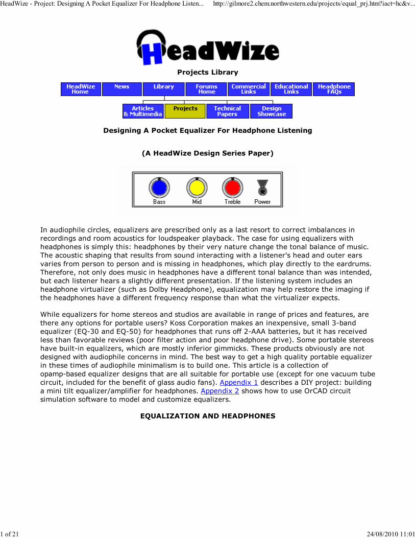
In addition to correcting tonal imbalances in headphones and recordings, equalizers can, to a
certain extent, alter the perceived spatial characteristics of headphones. Headphone acoustic
simulators, such as virtualizers, electronically process stereo and multi-channel signals so that
they image outside the listener's head - as though they were being projected by real
loudspeakers. When an acoustic simulator is not available, equalization can mimic some aspects
of normal hearing. For example, Ron Cole and John Sunier at the Binaural Source recommend a
"biophonic" curve (shown above) as a guide to setting equalizers to correct for ear canal
resonance and other differences in the spectrum between speaker listening and headphone
listening. (See Taking Sound in Another Direction for more information.) The curve suggests
boosting three center points and is the basis for this article's focus on 3-band equalizers.
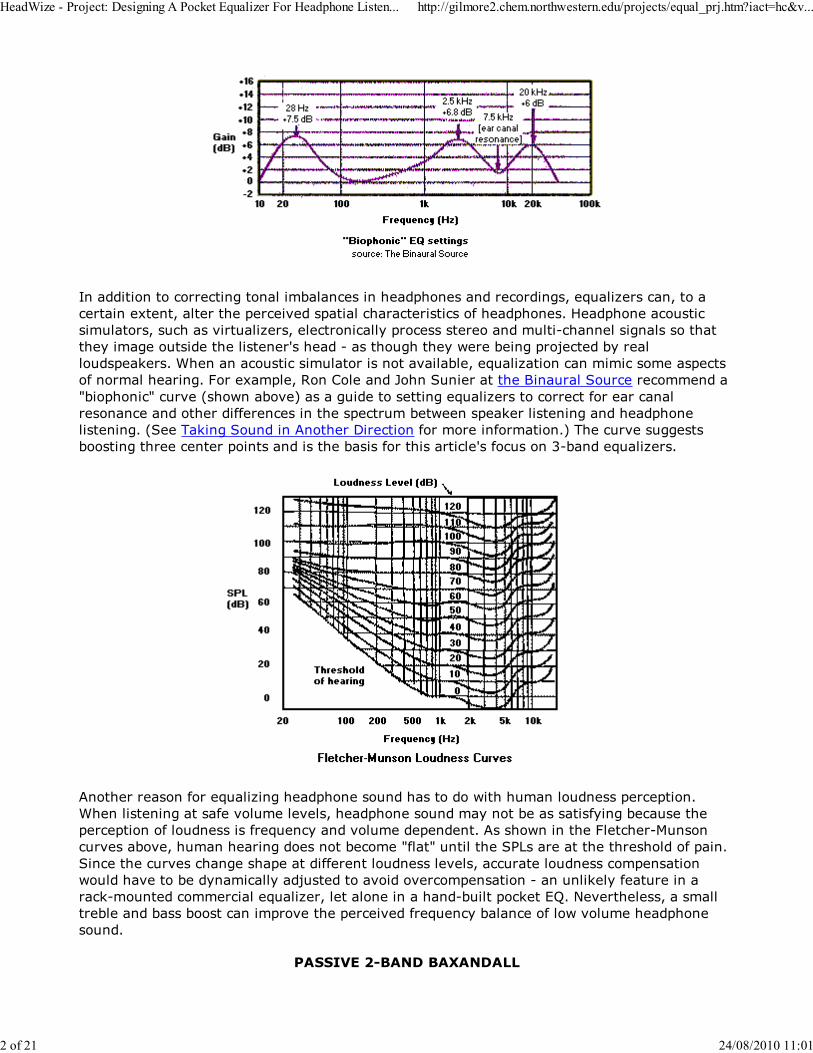
Another reason for equalizing headphone sound has to do with human loudness perception.
When listening at safe volume levels, headphone sound may not be as satisfying because the
perception of loudness is frequency and volume dependent. As shown in the Fletcher-Munson
curves above, human hearing does not become "flat" until the SPLs are at the threshold of pain.
Since the curves change shape at different loudness levels, accurate loudness compensation
would have to be dynamically adjusted to avoid overcompensation - an unlikely feature in a
rack-mounted commercial equalizer, let alone in a hand-built pocket EQ. Nevertheless, a small
treble and bass boost can improve the perceived frequency balance of low volume headphone
sound.
PASSIVE 2-BAND BAXANDALL
HeadWize - Project: Designing A Pocket Equalizer For Headphone Listen... http://gilmore2.chem.northwestern.edu/projects/equal_prj.htm?iact=hc&v...
2 of 21 24/08/2010 11:01
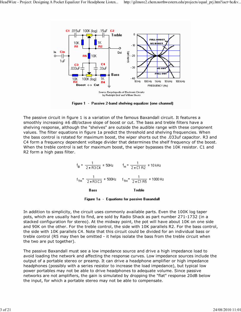
The passive circuit in figure 1 is a variation of the famous Baxandall circuit. It features a
smoothly increasing ±6 dB/octave slope of boost or cut. The bass and treble filters have a
shelving response, although the "shelves" are outside the audible range with these component
values. The filter equations in figure 1a predict the threshold and shelving frequencies. When
the bass control is rotated for maximum boost, the wiper shorts out the .033uf capacitor. R3 and
C4 form a frequency dependent voltage divider that determines the shelf frequency of the boost.
When the treble control is set for maximum boost, the wiper bypasses the 10K resistor. C1 and
R2 form a high pass filter.
In addition to simplicity, the circuit uses commonly available parts. Even the 100K log taper
pots, which are usually hard to find, are sold by Radio Shack as part number 271-1732 (in a
stacked configuration for stereo). At the midway point, the pot will have about 10K on one side
and 90K on the other. For the treble control, the side with 10K parallels R2. For the bass control,
the side with 10K parallels C4. Note that this circuit could be divided for an individual bass or
treble control (R5 may then be omitted - it helps isolate the bass from the treble circuit when
the two are put together).
The passive Baxandall must see a low impedance source and drive a high impedance load to
avoid loading the network and affecting the response curves. Low impedance sources include the
output of a portable stereo or preamp. It can drive a headphone amplifier or high impedance
headphones (possibly with a series resistor to increase the load impedance), but typical low
power portables may not be able to drive headphones to adequate volume. Since passive
networks are not amplifiers, the gain is simulated by dropping the "flat" response 20dB below
the input, for which a portable stereo may not be able to compensate.
HeadWize - Project: Designing A Pocket Equalizer For Headphone Listen... http://gilmore2.chem.northwestern.edu/projects/equal_prj.htm?iact=hc&v...
3 of 21 24/08/2010 11:01
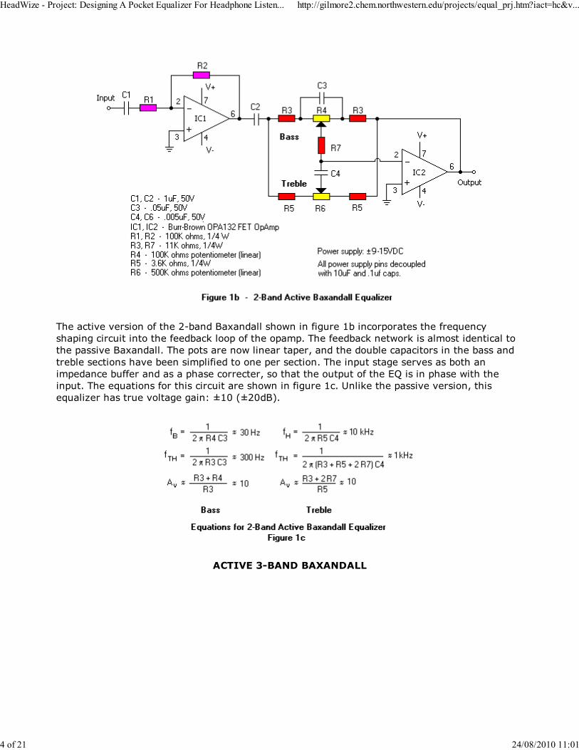
The active version of the 2-band Baxandall shown in figure 1b incorporates the frequency
shaping circuit into the feedback loop of the opamp. The feedback network is almost identical to
the passive Baxandall. The pots are now linear taper, and the double capacitors in the bass and
treble sections have been simplified to one per section. The input stage serves as both an
impedance buffer and as a phase correcter, so that the output of the EQ is in phase with the
input. The equations for this circuit are shown in figure 1c. Unlike the passive version, this
equalizer has true voltage gain: ±10 (±20dB).
ACTIVE 3-BAND BAXANDALL
HeadWize - Project: Designing A Pocket Equalizer For Headphone Listen... http://gilmore2.chem.northwestern.edu/projects/equal_prj.htm?iact=hc&v...
4 of 21 24/08/2010 11:01
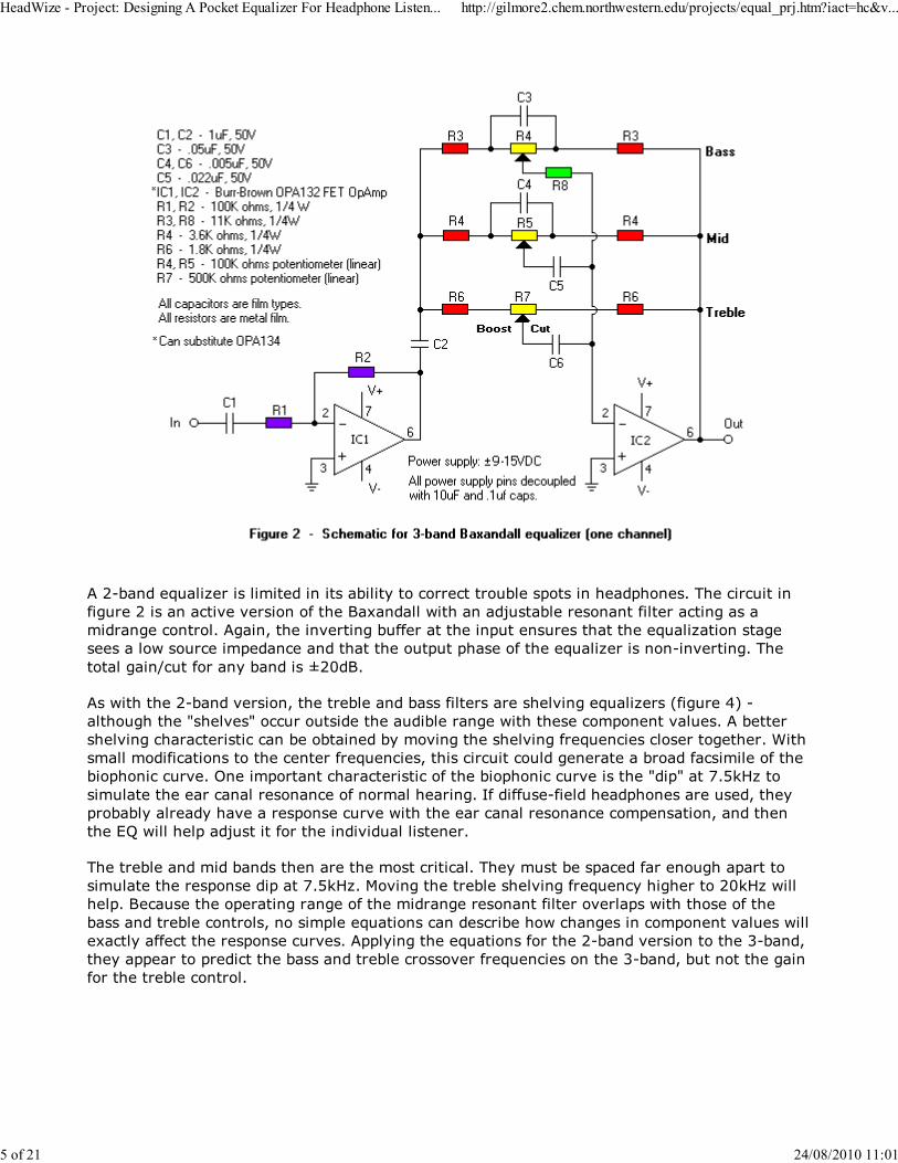
A 2-band equalizer is limited in its ability to correct trouble spots in headphones. The circuit in
figure 2 is an active version of the Baxandall with an adjustable resonant filter acting as a
midrange control. Again, the inverting buffer at the input ensures that the equalization stage
sees a low source impedance and that the output phase of the equalizer is non-inverting. The
total gain/cut for any band is ±20dB.
As with the 2-band version, the treble and bass filters are shelving equalizers (figure 4) -
although the "shelves" occur outside the audible range with these component values. A better
shelving characteristic can be obtained by moving the shelving frequencies closer together. With
small modifications to the center frequencies, this circuit could generate a broad facsimile of the
biophonic curve. One important characteristic of the biophonic curve is the "dip" at 7.5kHz to
simulate the ear canal resonance of normal hearing. If diffuse-field headphones are used, they
probably already have a response curve with the ear canal resonance compensation, and then
the EQ will help adjust it for the individual listener.
The treble and mid bands then are the most critical. They must be spaced far enough apart to
simulate the response dip at 7.5kHz. Moving the treble shelving frequency higher to 20kHz will
help. Because the operating range of the midrange resonant filter overlaps with those of the
bass and treble controls, no simple equations can describe how changes in component values will
exactly affect the response curves. Applying the equations for the 2-band version to the 3-band,
they appear to predict the bass and treble crossover frequencies on the 3-band, but not the gain
for the treble control.
HeadWize - Project: Designing A Pocket Equalizer For Headphone Listen... http://gilmore2.chem.northwestern.edu/projects/equal_prj.htm?iact=hc&v...
5 of 21 24/08/2010 11:01
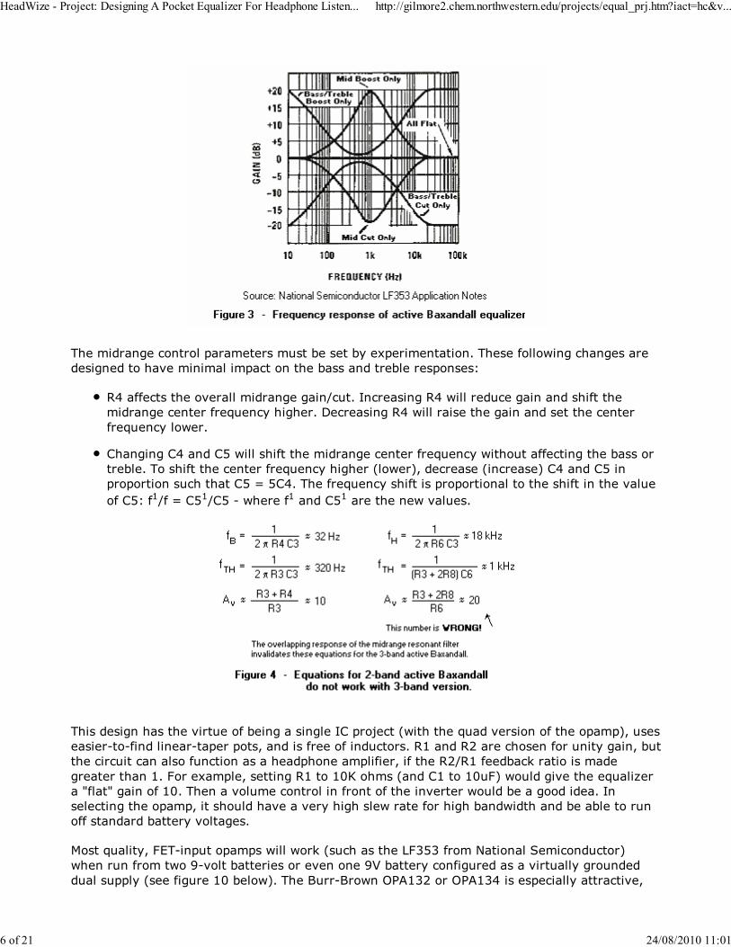
The midrange control parameters must be set by experimentation. These following changes are
designed to have minimal impact on the bass and treble responses:
R4 affects the overall midrange gain/cut. Increasing R4 will reduce gain and shift the
midrange center frequency higher. Decreasing R4 will raise the gain and set the center
frequency lower.
Changing C4 and C5 will shift the midrange center frequency without affecting the bass or
treble. To shift the center frequency higher (lower), decrease (increase) C4 and C5 in
proportion such that C5 = 5C4. The frequency shift is proportional to the shift in the value
of C5: f1/f = C51/C5 - where f1 and C51 are the new values.
This design has the virtue of being a single IC project (with the quad version of the opamp), uses
easier-to-find linear-taper pots, and is free of inductors. R1 and R2 are chosen for unity gain, but
the circuit can also function as a headphone amplifier, if the R2/R1 feedback ratio is made
greater than 1. For example, setting R1 to 10K ohms (and C1 to 10uF) would give the equalizer
a "flat" gain of 10. Then a volume control in front of the inverter would be a good idea. In
selecting the opamp, it should have a very high slew rate for high bandwidth and be able to run
off standard battery voltages.
Most quality, FET-input opamps will work (such as the LF353 from National Semiconductor)
when run from two 9-volt batteries or even one 9V battery configured as a virtually grounded
dual supply (see figure 10 below). The Burr-Brown OPA132 or OPA134 is especially attractive,
HeadWize - Project: Designing A Pocket Equalizer For Headphone Listen... http://gilmore2.chem.northwestern.edu/projects/equal_prj.htm?iact=hc&v...
6 of 21 24/08/2010 11:01
with a 20uV/sec slew rate, no phase inversion and a power supply as low as ±2.5VDC. For the
active equalizers circuit shown in this article, the recommended battery supply is ±9V. Smaller
power supplies will likely cause an equalizer to clip frequently because of the high gains
involved.
BANDPASS EQUALIZERS
Although the Baxandall circuits are good for general purposes, there are discriminating
headphone connoisseurs who insist on doing the least sonic harm when applying equalization. In
particular, the shelving characteristic of bass and treble bands can make recordings sound
bass-heavy or excessively noisy (noise is less of a problem when listening to digital recordings).
Parametric equalizers have a bandwidth control (also called a Q control) for each band to further
narrow the response of a resonant filter. Since each band has a minimum of 3 adjustments
(gain, frequency and bandwidth), a 3-band parametric would have at least 9 controls and a
barrel of parts and is impractical to house in a truly pocket-sized enclosure.
The bandpass filters of an octave equalizer can be preset with a high Q. A 3-band graphic
equalizer with high Q bands is rare, because 3 bands usually do not offer enough flexibility when
the filter action is narrow. However, there are situations where a 3-band graphic equalizer might
be adequate, such as when the EQ is application specific and the center frequencies are known in
advance. Again, the number of parts to build a high Q 3-band equalizer is probably more than
can fit into a small enclosure (although there are "graphic EQs on a chip" that might work).
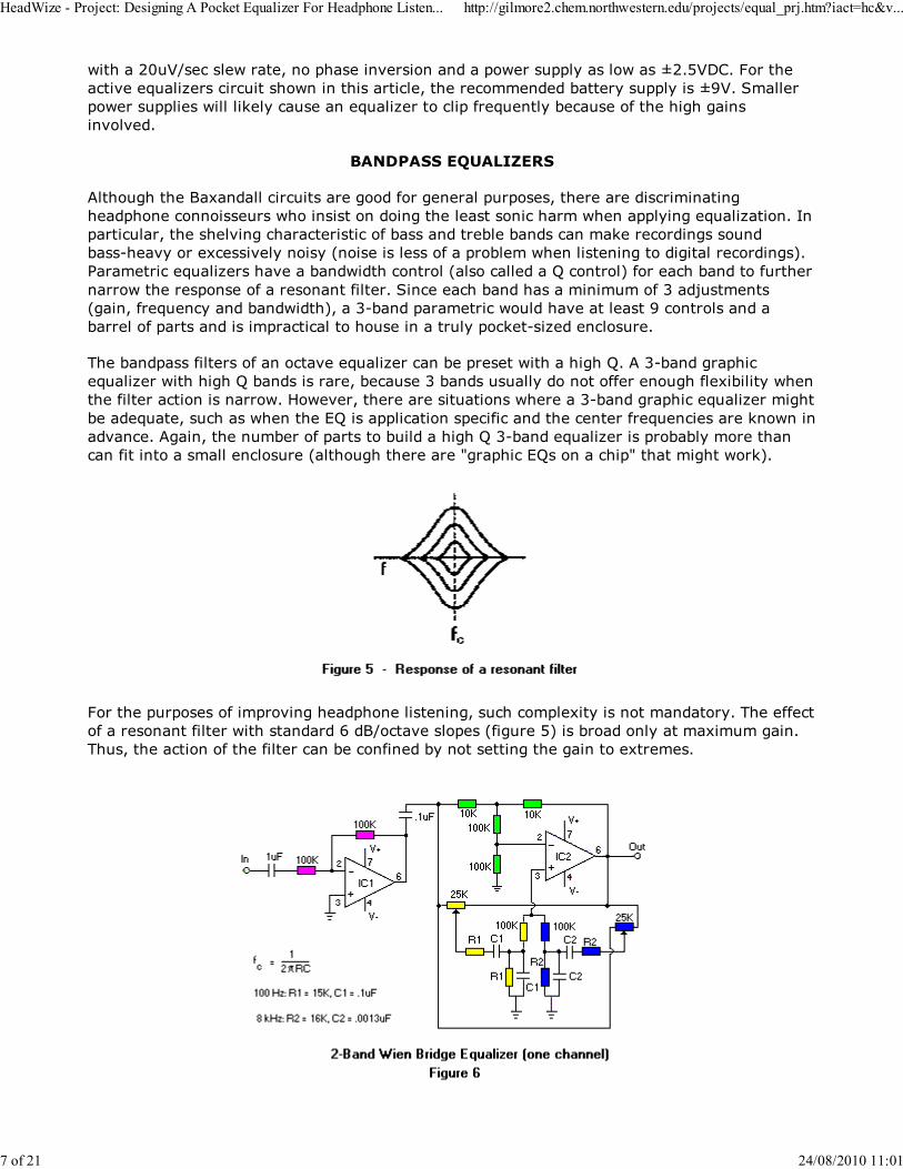
For the purposes of improving headphone listening, such complexity is not mandatory. The effect
of a resonant filter with standard 6 dB/octave slopes (figure 5) is broad only at maximum gain.
Thus, the action of the filter can be confined by not setting the gain to extremes.
HeadWize - Project: Designing A Pocket Equalizer For Headphone Listen... http://gilmore2.chem.northwestern.edu/projects/equal_prj.htm?iact=hc&v...
7 of 21 24/08/2010 11:01
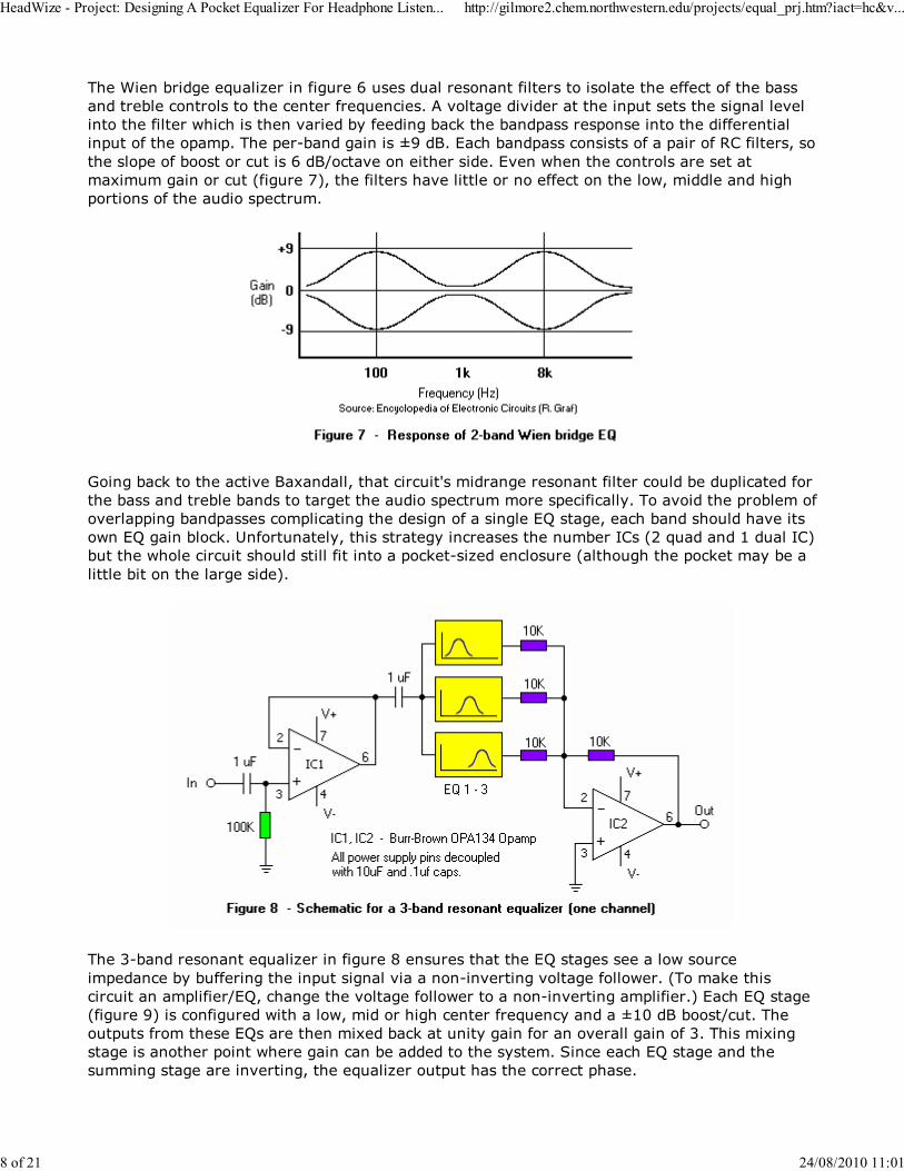
The Wien bridge equalizer in figure 6 uses dual resonant filters to isolate the effect of the bass
and treble controls to the center frequencies. A voltage divider at the input sets the signal level
into the filter which is then varied by feeding back the bandpass response into the differential
input of the opamp. The per-band gain is ±9 dB. Each bandpass consists of a pair of RC filters, so
the slope of boost or cut is 6 dB/octave on either side. Even when the controls are set at
maximum gain or cut (figure 7), the filters have little or no effect on the low, middle and high
portions of the audio spectrum.
Going back to the active Baxandall, that circuit's midrange resonant filter could be duplicated for
the bass and treble bands to target the audio spectrum more specifically. To avoid the problem of
overlapping bandpasses complicating the design of a single EQ stage, each band should have its
own EQ gain block. Unfortunately, this strategy increases the number ICs (2 quad and 1 dual IC)
but the whole circuit should still fit into a pocket-sized enclosure (although the pocket may be a
little bit on the large side).
The 3-band resonant equalizer in figure 8 ensures that the EQ stages see a low source
impedance by buffering the input signal via a non-inverting voltage follower. (To make this
circuit an amplifier/EQ, change the voltage follower to a non-inverting amplifier.) Each EQ stage
(figure 9) is configured with a low, mid or high center frequency and a ±10 dB boost/cut. The
outputs from these EQs are then mixed back at unity gain for an overall gain of 3. This mixing
stage is another point where gain can be added to the system. Since each EQ stage and the
summing stage are inverting, the equalizer output has the correct phase.
HeadWize - Project: Designing A Pocket Equalizer For Headphone Listen... http://gilmore2.chem.northwestern.edu/projects/equal_prj.htm?iact=hc&v...
8 of 21 24/08/2010 11:01
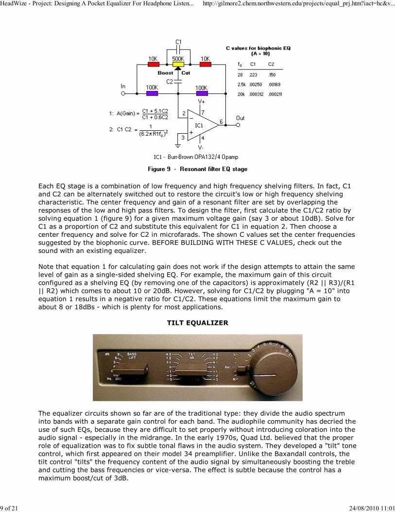
Each EQ stage is a combination of low frequency and high frequency shelving filters. In fact, C1
and C2 can be alternately switched out to restore the circuit's low or high frequency shelving
characteristic. The center frequency and gain of a resonant filter are set by overlapping the
responses of the low and high pass filters. To design the filter, first calculate the C1/C2 ratio by
solving equation 1 (figure 9) for a given maximum voltage gain (say 3 or about 10dB). Solve for
C1 as a proportion of C2 and substitute this equivalent for C1 in equation 2. Then choose a
center frequency and solve for C2 in microfarads. The shown C values set the center frequencies
suggested by the biophonic curve. BEFORE BUILDING WITH THESE C VALUES, check out the
sound with an existing equalizer.
Note that equation 1 for calculating gain does not work if the design attempts to attain the same
level of gain as a single-sided shelving EQ. For example, the maximum gain of this circuit
configured as a shelving EQ (by removing one of the capacitors) is approximately (R2 || R3)/(R1
|| R2) which comes to about 10 or 20dB. However, solving for C1/C2 by plugging "A = 10" into
equation 1 results in a negative ratio for C1/C2. These equations limit the maximum gain to
about 8 or 18dBs - which is plenty for most applications.
TILT EQUALIZER
The equalizer circuits shown so far are of the traditional type: they divide the audio spectrum
into bands with a separate gain control for each band. The audiophile community has decried the
use of such EQs, because they are difficult to set properly without introducing coloration into the
audio signal - especially in the midrange. In the early 1970s, Quad Ltd. believed that the proper
role of equalization was to fix subtle tonal flaws in the audio system. They developed a "tilt" tone
control, which first appeared on their model 34 preamplifier. Unlike the Baxandall controls, the
tilt control "tilts" the frequency content of the audio signal by simultaneously boosting the treble
and cutting the bass frequencies or vice-versa. The effect is subtle because the control has a
maximum boost/cut of 3dB.
HeadWize - Project: Designing A Pocket Equalizer For Headphone Listen... http://gilmore2.chem.northwestern.edu/projects/equal_prj.htm?iact=hc&v...
9 of 21 24/08/2010 11:01
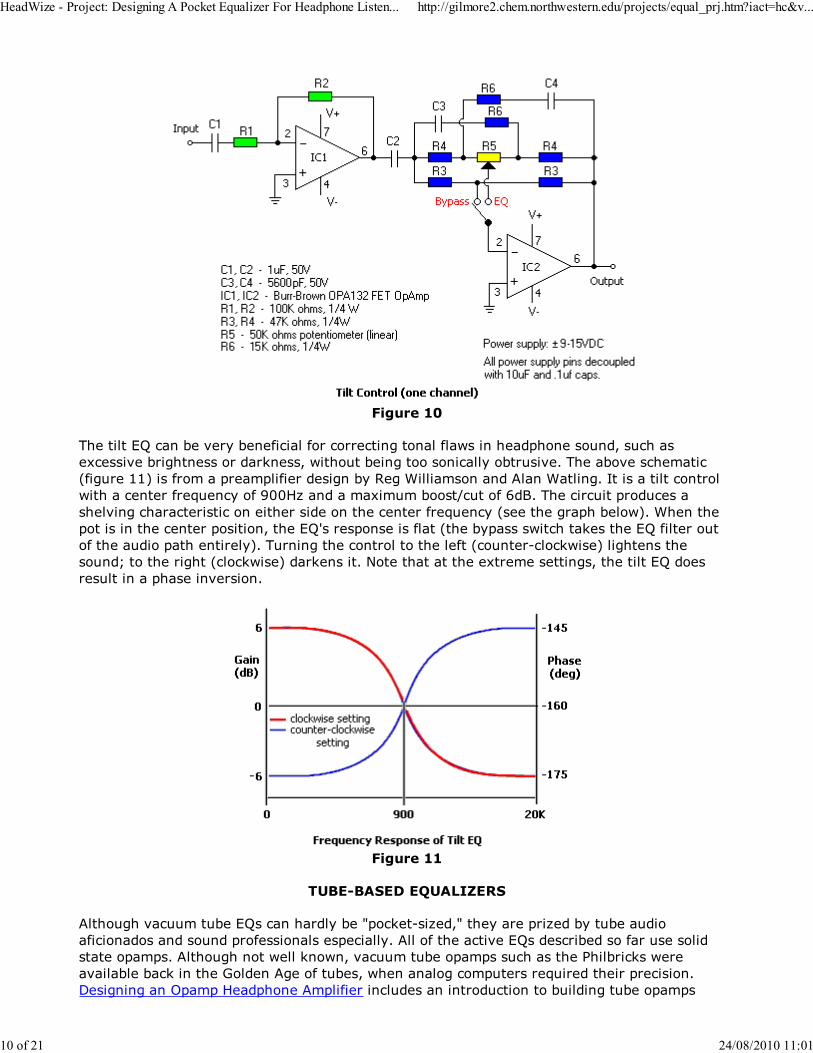
Figure 10
The tilt EQ can be very beneficial for correcting tonal flaws in headphone sound, such as
excessive brightness or darkness, without being too sonically obtrusive. The above schematic
(figure 11) is from a preamplifier design by Reg Williamson and Alan Watling. It is a tilt control
with a center frequency of 900Hz and a maximum boost/cut of 6dB. The circuit produces a
shelving characteristic on either side on the center frequency (see the graph below). When the
pot is in the center position, the EQ's response is flat (the bypass switch takes the EQ filter out
of the audio path entirely). Turning the control to the left (counter-clockwise) lightens the
sound; to the right (clockwise) darkens it. Note that at the extreme settings, the tilt EQ does
result in a phase inversion.
Figure 11
TUBE-BASED EQUALIZERS
Although vacuum tube EQs can hardly be "pocket-sized," they are prized by tube audio
aficionados and sound professionals especially. All of the active EQs described so far use solid
state opamps. Although not well known, vacuum tube opamps such as the Philbricks were
available back in the Golden Age of tubes, when analog computers required their precision.
Designing an Opamp Headphone Amplifier includes an introduction to building tube opamps
HeadWize - Project: Designing A Pocket Equalizer For Headphone Listen... http://gilmore2.chem.northwestern.edu/projects/equal_prj.htm?iact=hc&v...
10 of 21 24/08/2010 11:01
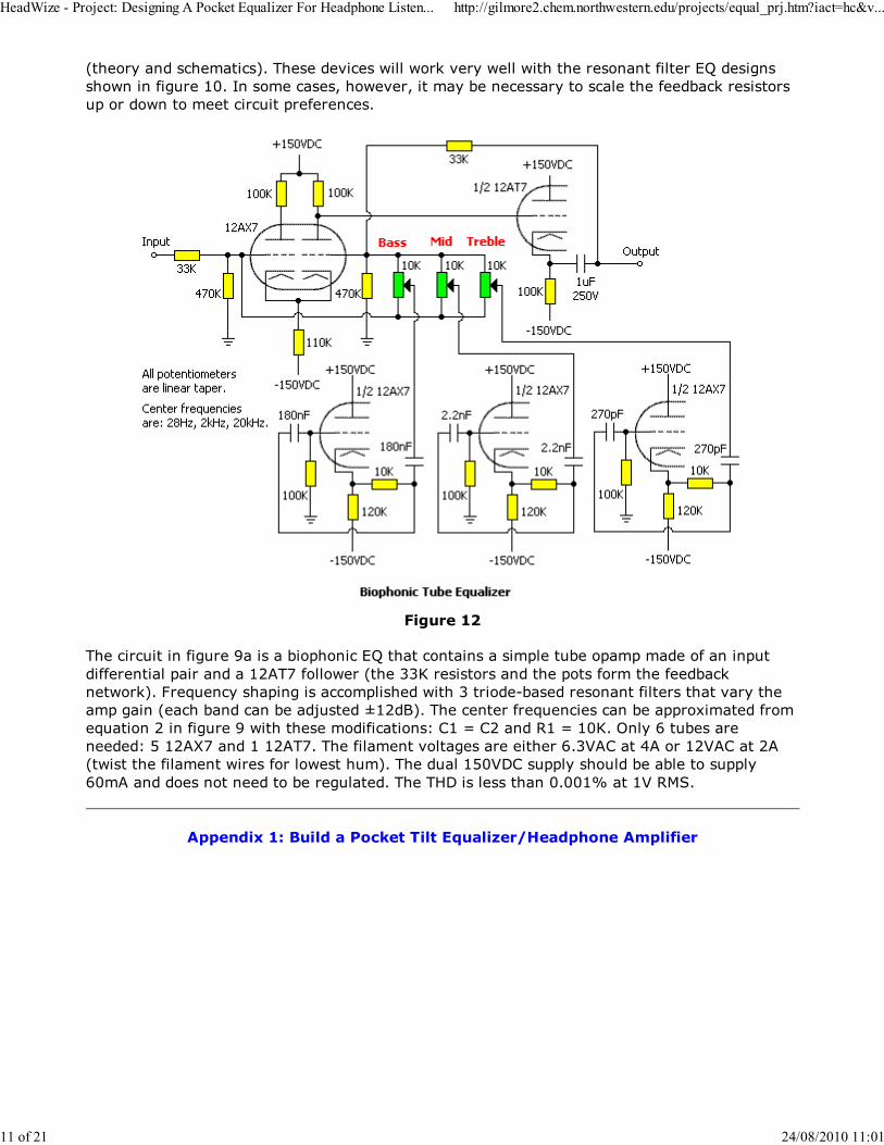
(theory and schematics). These devices will work very well with the resonant filter EQ designs
shown in figure 10. In some cases, however, it may be necessary to scale the feedback resistors
up or down to meet circuit preferences.
Figure 12
The circuit in figure 9a is a biophonic EQ that contains a simple tube opamp made of an input
differential pair and a 12AT7 follower (the 33K resistors and the pots form the feedback
network). Frequency shaping is accomplished with 3 triode-based resonant filters that vary the
amp gain (each band can be adjusted ±12dB). The center frequencies can be approximated from
equation 2 in figure 9 with these modifications: C1 = C2 and R1 = 10K. Only 6 tubes are
needed: 5 12AX7 and 1 12AT7. The filament voltages are either 6.3VAC at 4A or 12VAC at 2A
(twist the filament wires for lowest hum). The dual 150VDC supply should be able to supply
60mA and does not need to be regulated. The THD is less than 0.001% at 1V RMS.
Appendix 1: Build a Pocket Tilt Equalizer/Headphone Amplifier
HeadWize - Project: Designing A Pocket Equalizer For Headphone Listen... http://gilmore2.chem.northwestern.edu/projects/equal_prj.htm?iact=hc&v...
11 of 21 24/08/2010 11:01
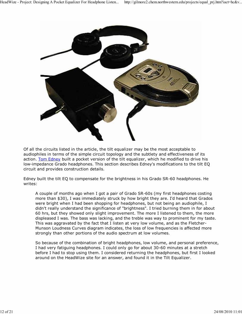
Of all the circuits listed in the article, the tilt equalizer may be the most acceptable to
audiophiles in terms of the simple circuit topology and the subtlety and effectiveness of its
action. Tom Edney built a pocket version of the tilt equalizer, which he modified to drive his
low-impedance Grado headphones. This section describes Edney's modifications to the tilt EQ
circuit and provides construction details.
Edney built the tilt EQ to compensate for the brightness in his Grado SR-60 headphones. He
writes:
A couple of months ago when I got a pair of Grado SR-60s (my first headphones costing
more than $30), I was immediately struck by how bright they are. I'd heard that Grados
were bright when I had been shopping for headphones, but not being an audiophile, I
didn't really understand the significance of "brightness". I tried burning them in for about
60 hrs, but they showed only slight improvement. The more I listened to them, the more
displeased I was. The bass was lacking, and the treble was way to prominent for my taste.
This was aggravated by the fact that I listen at very low volume, and as the Fletcher-
Munson Loudness Curves diagram indicates, the loss of low frequencies is affected more
strongly than other portions of the audio spectrum at low volumes.
So because of the combination of bright headphones, low volume, and personal preference,
I had very fatiguing headphones. I could only go for about 30-60 minutes at a stretch
before I had to stop using them. I considered returning the headphones, but first I looked
around on the HeadWize site for an answer, and found it in the Tilt Equalizer.
HeadWize - Project: Designing A Pocket Equalizer For Headphone Listen... http://gilmore2.chem.northwestern.edu/projects/equal_prj.htm?iact=hc&v...
12 of 21 24/08/2010 11:01
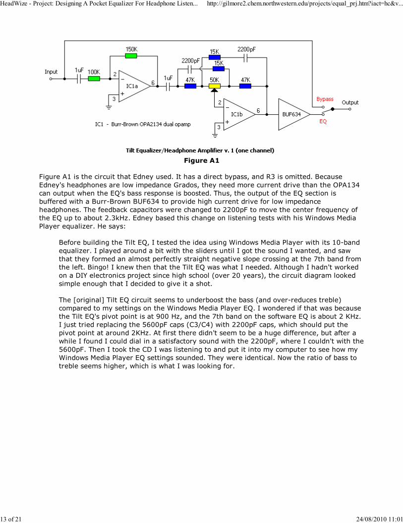
Figure A1
Figure A1 is the circuit that Edney used. It has a direct bypass, and R3 is omitted. Because
Edney's headphones are low impedance Grados, they need more current drive than the OPA134
can output when the EQ's bass response is boosted. Thus, the output of the EQ section is
buffered with a Burr-Brown BUF634 to provide high current drive for low impedance
headphones. The feedback capacitors were changed to 2200pF to move the center frequency of
the EQ up to about 2.3kHz. Edney based this change on listening tests with his Windows Media
Player equalizer. He says:
Before building the Tilt EQ, I tested the idea using Windows Media Player with its 10-band
equalizer. I played around a bit with the sliders until I got the sound I wanted, and saw
that they formed an almost perfectly straight negative slope crossing at the 7th band from
the left. Bingo! I knew then that the Tilt EQ was what I needed. Although I hadn't worked
on a DIY electronics project since high school (over 20 years), the circuit diagram looked
simple enough that I decided to give it a shot.
The [original] Tilt EQ circuit seems to underboost the bass (and over-reduces treble)
compared to my settings on the Windows Media Player EQ. I wondered if that was because
the Tilt EQ's pivot point is at 900 Hz, and the 7th band on the software EQ is about 2 KHz.
I just tried replacing the 5600pF caps (C3/C4) with 2200pF caps, which should put the
pivot point at around 2KHz. At first there didn't seem to be a huge difference, but after a
while I found I could dial in a satisfactory sound with the 2200pF, where I couldn't with the
5600pF. Then I took the CD I was listening to and put it into my computer to see how my
Windows Media Player EQ settings sounded. They were identical. Now the ratio of bass to
treble seems higher, which is what I was looking for.
HeadWize - Project: Designing A Pocket Equalizer For Headphone Listen... http://gilmore2.chem.northwestern.edu/projects/equal_prj.htm?iact=hc&v...
13 of 21 24/08/2010 11:01
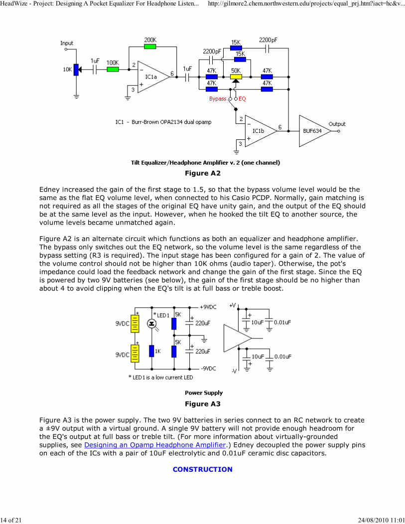
Figure A2
Edney increased the gain of the first stage to 1.5, so that the bypass volume level would be the
same as the flat EQ volume level, when connected to his Casio PCDP. Normally, gain matching is
not required as all the stages of the original EQ have unity gain, and the output of the EQ should
be at the same level as the input. However, when he hooked the tilt EQ to another source, the
volume levels became unmatched again.
Figure A2 is an alternate circuit which functions as both an equalizer and headphone amplifier.
The bypass only switches out the EQ network, so the volume level is the same regardless of the
bypass setting (R3 is required). The input stage has been configured for a gain of 2. The value of
the volume control should not be higher than 10K ohms (audio taper). Otherwise, the pot's
impedance could load the feedback network and change the gain of the first stage. Since the EQ
is powered by two 9V batteries (see below), the gain of the first stage should be no higher than
about 4 to avoid clipping when the EQ's tilt is at full bass or treble boost.
Figure A3
Figure A3 is the power supply. The two 9V batteries in series connect to an RC network to create
a ±9V output with a virtual ground. A single 9V battery will not provide enough headroom for
the EQ's output at full bass or treble tilt. (For more information about virtually-grounded
supplies, see Designing an Opamp Headphone Amplifier.) Edney decoupled the power supply pins
on each of the ICs with a pair of 10uF electrolytic and 0.01uF ceramic disc capacitors.
CONSTRUCTION
HeadWize - Project: Designing A Pocket Equalizer For Headphone Listen... http://gilmore2.chem.northwestern.edu/projects/equal_prj.htm?iact=hc&v...
14 of 21 24/08/2010 11:01
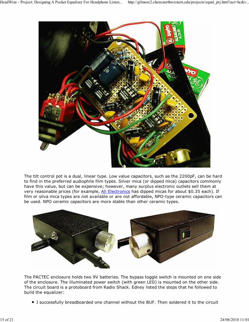
The tilt control pot is a dual, linear type. Low value capacitors, such as the 2200pF, can be hard
to find in the preferred audiophile film types. Silver mica (or dipped mica) capacitors commonly
have this value, but can be expensive; however, many surplus electronic outlets sell them at
very reasonable prices (for example, All Electronics has dipped micas for about $0.35 each). If
film or silva mica types are not available or are not affordable, NPO-type ceramic capacitors can
be used. NPO ceramic capacitors are more stable than other ceramic types.
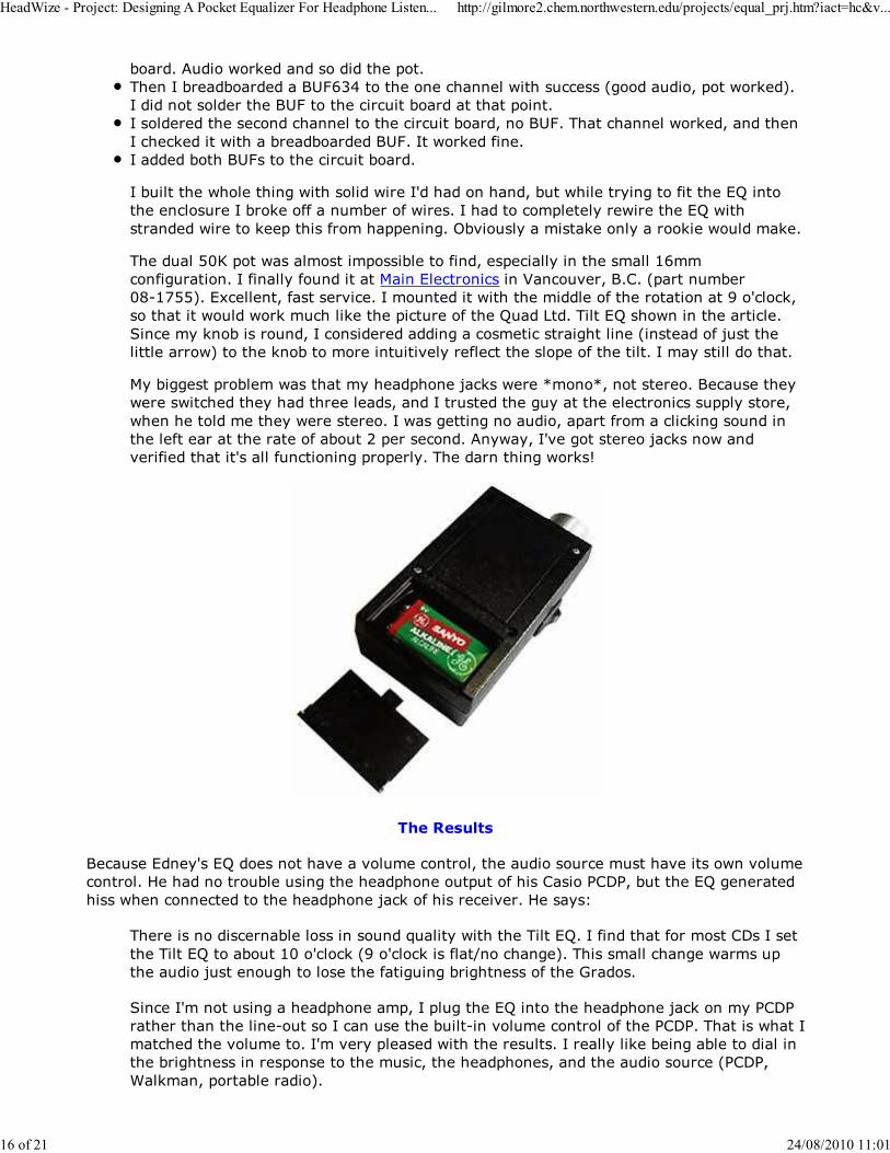
The PACTEC enclosure holds two 9V batteries. The bypass toggle switch is mounted on one side
of the enclosure. The illuminated power switch (with green LED) is mounted on the other side.
The circuit board is a protoboard from Radio Shack. Edney listed the steps that he followed to
build the equalizer:
I successfully breadboarded one channel without the BUF. Then soldered it to the circuit
HeadWize - Project: Designing A Pocket Equalizer For Headphone Listen... http://gilmore2.chem.northwestern.edu/projects/equal_prj.htm?iact=hc&v...
15 of 21 24/08/2010 11:01
board. Audio worked and so did the pot.
Then I breadboarded a BUF634 to the one channel with success (good audio, pot worked).
I did not solder the BUF to the circuit board at that point.
I soldered the second channel to the circuit board, no BUF. That channel worked, and then
I checked it with a breadboarded BUF. It worked fine.
I added both BUFs to the circuit board.
I built the whole thing with solid wire I'd had on hand, but while trying to fit the EQ into
the enclosure I broke off a number of wires. I had to completely rewire the EQ with
stranded wire to keep this from happening. Obviously a mistake only a rookie would make.
The dual 50K pot was almost impossible to find, especially in the small 16mm
configuration. I finally found it at Main Electronics in Vancouver, B.C. (part number
08-1755). Excellent, fast service. I mounted it with the middle of the rotation at 9 o'clock,
so that it would work much like the picture of the Quad Ltd. Tilt EQ shown in the article.
Since my knob is round, I considered adding a cosmetic straight line (instead of just the
little arrow) to the knob to more intuitively reflect the slope of the tilt. I may still do that.
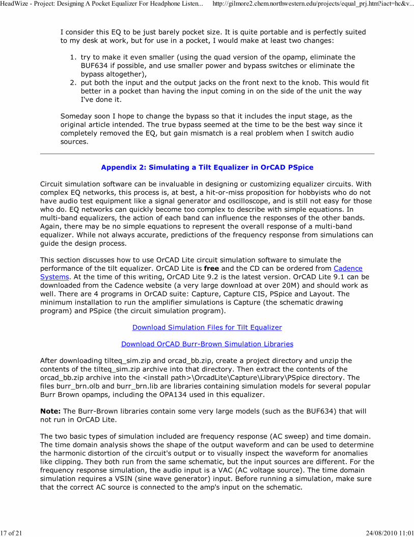
My biggest problem was that my headphone jacks were *mono*, not stereo. Because they
were switched they had three leads, and I trusted the guy at the electronics supply store,
when he told me they were stereo. I was getting no audio, apart from a clicking sound in
the left ear at the rate of about 2 per second. Anyway, I've got stereo jacks now and
verified that it's all functioning properly. The darn thing works!
The Results
Because Edney's EQ does not have a volume control, the audio source must have its own volume
control. He had no trouble using the headphone output of his Casio PCDP, but the EQ generated
hiss when connected to the headphone jack of his receiver. He says:
There is no discernable loss in sound quality with the Tilt EQ. I find that for most CDs I set
the Tilt EQ to about 10 o'clock (9 o'clock is flat/no change). This small change warms up
the audio just enough to lose the fatiguing brightness of the Grados.
Since I'm not using a headphone amp, I plug the EQ into the headphone jack on my PCDP
rather than the line-out so I can use the built-in volume control of the PCDP. That is what I
matched the volume to. I'm very pleased with the results. I really like being able to dial in
the brightness in response to the music, the headphones, and the audio source (PCDP,
Walkman, portable radio).
HeadWize - Project: Designing A Pocket Equalizer For Headphone Listen... http://gilmore2.chem.northwestern.edu/projects/equal_prj.htm?iact=hc&v...
16 of 21 24/08/2010 11:01
I consider this EQ to be just barely pocket size. It is quite portable and is perfectly suited
to my desk at work, but for use in a pocket, I would make at least two changes:
try to make it even smaller (using the quad version of the opamp, eliminate the
BUF634 if possible, and use smaller power and bypass switches or eliminate the
bypass altogether),
1.
put both the input and the output jacks on the front next to the knob. This would fit
better in a pocket than having the input coming in on the side of the unit the way
I've done it.
2.
Someday soon I hope to change the bypass so that it includes the input stage, as the
original article intended. The true bypass seemed at the time to be the best way since it
completely removed the EQ, but gain mismatch is a real problem when I switch audio
sources.
Appendix 2: Simulating a Tilt Equalizer in OrCAD PSpice
Circuit simulation software can be invaluable in designing or customizing equalizer circuits. With
complex EQ networks, this process is, at best, a hit-or-miss proposition for hobbyists who do not
have audio test equipment like a signal generator and oscilloscope, and is still not easy for those
who do. EQ networks can quickly become too complex to describe with simple equations. In
multi-band equalizers, the action of each band can influence the responses of the other bands.
Again, there may be no simple equations to represent the overall response of a multi-band
equalizer. While not always accurate, predictions of the frequency response from simulations can
guide the design process.
This section discusses how to use OrCAD Lite circuit simulation software to simulate the
performance of the tilt equalizer. OrCAD Lite is free and the CD can be ordered from Cadence
Systems. At the time of this writing, OrCAD Lite 9.2 is the latest version. OrCAD Lite 9.1 can be
downloaded from the Cadence website (a very large download at over 20M) and should work as
well. There are 4 programs in OrCAD suite: Capture, Capture CIS, PSpice and Layout. The
minimum installation to run the amplifier simulations is Capture (the schematic drawing
program) and PSpice (the circuit simulation program).
Download Simulation Files for Tilt Equalizer
Download OrCAD Burr-Brown Simulation Libraries
After downloading tilteq_sim.zip and orcad_bb.zip, create a project directory and unzip the
contents of the tilteq_sim.zip archive into that directory. Then extract the contents of the
orcad_bb.zip archive into the <install path>\OrcadLite\Capture\Library\PSpice directory. The
files burr_brn.olb and burr_brn.lib are libraries containing simulation models for several popular
Burr Brown opamps, including the OPA134 used in this equalizer.
Note: The Burr-Brown libraries contain some very large models (such as the BUF634) that will
not run in OrCAD Lite.
The two basic types of simulation included are frequency response (AC sweep) and time domain.
The time domain analysis shows the shape of the output waveform and can be used to determine
the harmonic distortion of the circuit's output or to visually inspect the waveform for anomalies
like clipping. They both run from the same schematic, but the input sources are different. For the
frequency response simulation, the audio input is a VAC (AC voltage source). The time domain
simulation requires a VSIN (sine wave generator) input. Before running a simulation, make sure
that the correct AC source is connected to the amp's input on the schematic.
HeadWize - Project: Designing A Pocket Equalizer For Headphone Listen... http://gilmore2.chem.northwestern.edu/projects/equal_prj.htm?iact=hc&v...
17 of 21 24/08/2010 11:01
The following instructions for using the simulation files are not a complete tutorial for OrCAD.
The OrCAD HELP files and online manuals include tutorials for those who want to learn more
about OrCAD.
Frequency Response (AC Sweep) Analysis
Run OrCAD Capture and open the project file "tilt_eq.opj".1.
In the Project Manager window, expand the "PSPICE Resources|Simulation Profiles" folder.
Right click on "Schematic1-freq_resp" and select "Make Active."
2.
In the Project Manager window, expand the "Design Resources|.\tilt_eq.dsn|SCHEMATIC1"
folder and double click on "PAGE1".
3.
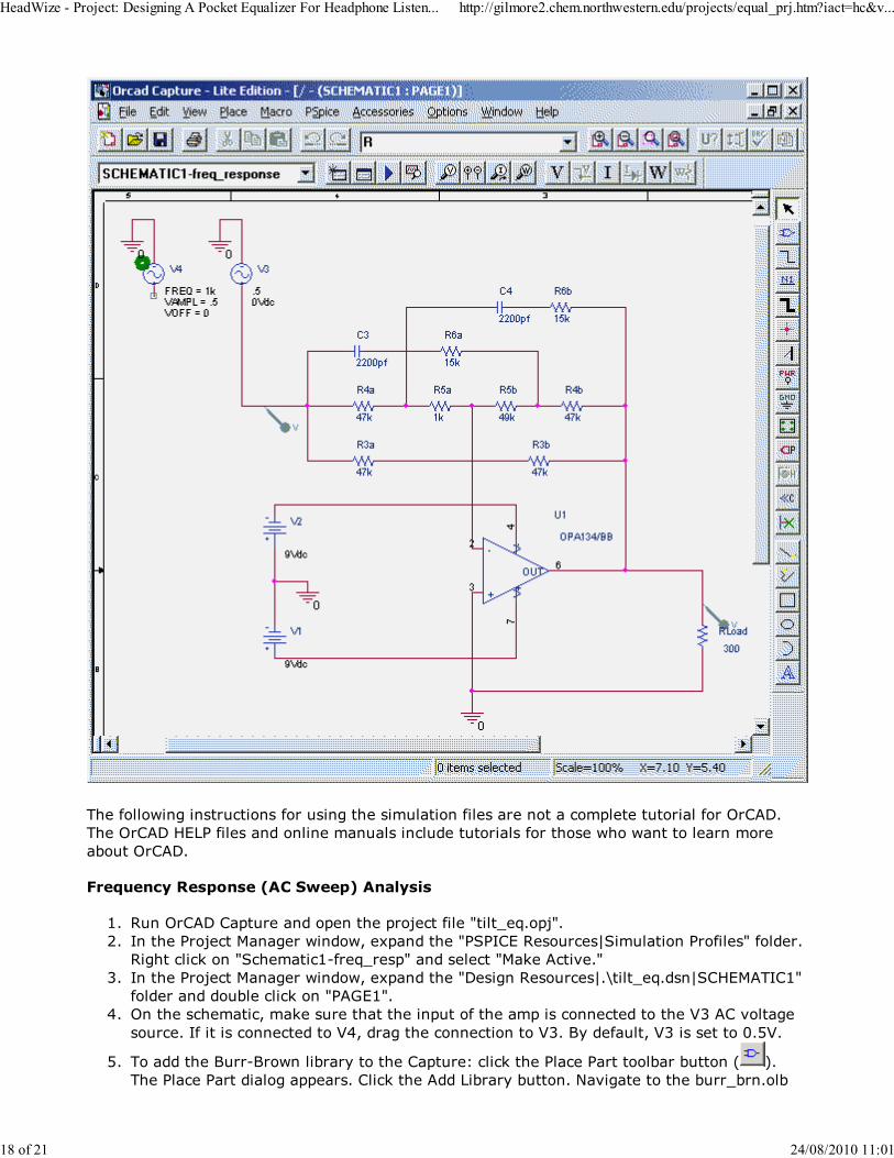
On the schematic, make sure that the input of the amp is connected to the V3 AC voltage
source. If it is connected to V4, drag the connection to V3. By default, V3 is set to 0.5V.
4.
To add the Burr-Brown library to the Capture: click the Place Part toolbar button ( ).
The Place Part dialog appears. Click the Add Library button. Navigate to the burr_brn.olb
5.
HeadWize - Project: Designing A Pocket Equalizer For Headphone Listen... http://gilmore2.chem.northwestern.edu/projects/equal_prj.htm?iact=hc&v...
18 of 21 24/08/2010 11:01
file and click Open. Make sure that the analog.olb and source.olb libraries are also listed in
the dialog. Click the Cancel button to close the Place Part dialog.
From the menu, select PSpice|Edit Simulation Profile. The Simulation Settings dialog
appears. The settings should be as follows:
Analysis Type: AC Sweep/Noise
AC Sweep Type: Logarithmic (Decade), Start Freq = 10, End Freq = 100K,
Points/Decade = 100
19.
To add the Burr-Brown library to PSpice: Click the "Libraries" tab. Click the Browse button
and navigate to the the burr_brn.lib file. Click the Add To Design button. If the nom.lib file
is not already listed in the dialog list, add it now. Then close the Simulation Settings
dialog.
20.
To display the input and output frequency responses on a single graph, voltage probes
must be placed on the input and output points of the schematic. The probes should already
exist on the schematic. If not, here's how to add them: Click the Voltage/Level Marker (
) on the toolbar and place a marker at the junction of R3a, R4a and C3. Place another
marker just above RLoad.
21.
OrCAD does not have a functional model of a potentiometer. R5a and R5b represent a
50K-ohm pot. When R5a = R5b = 25K ohms, the pot's wiper is at the center. To "rotate"
the pot to a clockwise or counter-clockwise position, make R5a << R5b or R5a >> R5b, but
in all cases, the sum of these resistors must total 50K. For example, in the schematic
shown above, the equalizer is set for a bass tilt with R5a = 1K and R5b = 49K.
22.
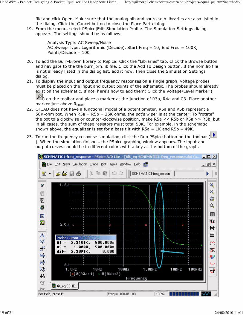
To run the frequency response simulation, click the Run PSpice button on the toolbar (
). When the simulation finishes, the PSpice graphing window appears. The input and
output curves should be in different colors with a key at the bottom of the graph.
23.
HeadWize - Project: Designing A Pocket Equalizer For Headphone Listen... http://gilmore2.chem.northwestern.edu/projects/equal_prj.htm?iact=hc&v...
19 of 21 24/08/2010 11:01
The horizontal axis of the graph does not have adequate markings to determine center
frequency of the tilt by eye. To display the PSpice cursor, select Trace|Cursor|Display from
the PSpice menu. A vertical cursor line appears on the graph, and the Probe Cursor
window appears over the graph. Drag the cursor to the point where the output curve
(shown here in green) intersects with the input curve (shown here in red). Then, the exact
coordinates of the intersection are shown in the Probe Cursor window on the A1 line. The
first number (2.3101K) is the center frequency. The second number (500mV) is the
corresponding voltage for that frequency.
26.
Time Domain (Transient) Analysis
On the Capture schematic, make sure that the input of the amp is connected to the V2
sinewave source (the default values are: VAMPL=0.5, Freq. = 1K, VOFF = 0). If it is
connected to V3, drag the connection to V2.
1.
In the Project Manager window, expand the "PSPICE Resources|Simulation Profiles" folder.
Right click on "Schematic1-transient" and select "Make Active"
2.
From the menu, select PSpice|Edit Simulation Profile. The Simulation Settings dialog
appears. The settings should be as follows:
Analysis Type: Time Domain(Transient)
Transient Options: Run to time = 10ms, Start saving data after = 0ms, Max. step
size = 0.001ms
3.
To display the input and output waveforms on a single graph, voltage probes must be
placed on the input and output points of the schematic. If the probes are not already on
the schematic, follow the procedure in step 8 of the Frequency Response Analysis to add
them.
4.
To run the time domain simulation, click the Run PSpice button on the toolbar ( ). When
the simulation finishes, the PSpice graphing window appears. The input and output curves
should be in different colors with a key at the bottom of the graph.
5.
To determine the harmonic distortion at 1KHz (the sine wave frequency), harmonics in the
output waveform must be separated out through a Fourier Transform. In the PSpice
window, press the FFT toolbar button ( ). The PSpice graph changes to show the
harmonics for the input and output waveforms. The input and output curves should be in
different colors with a key at the bottom of the graph.
6.
The fundamental frequency at 1KHz will have the largest spike. The other harmonics are
too small to be seen at the default magnification. In the PSpice window, press the Zoom
Area toolbar button ( ) and drag a small rectangle in the lower left corner of the FFT
graph. The graph now displays a magnified view of the selected area. Continue zooming in
until the harmonic spikes at 2KHz, 3KHz, etc. are visible.
7.
Harmonic spikes should exist for the output waveform only. The input is an ideal sine wave
generator and has no distortion. To calculate total harmonic distortion, add up the spike
values (voltages) at frequencies above 1KHz and divide by the voltage at 1KHz (the
fundamental).
8.
Additional Simulation Tips
To change the value of any component on a schematic in the Capture program,
double-click on the value and enter a new value at the prompt.
Note: Simulations only approximate the performance of a circuit. The actual performance may
vary considerably from the simulation as determined by a number of factors, including the
accuracy of the component models, and layout and construction techniques.
HeadWize - Project: Designing A Pocket Equalizer For Headphone Listen... http://gilmore2.chem.northwestern.edu/projects/equal_prj.htm?iact=hc&v...
20 of 21 24/08/2010 11:01
References:
Berlin, Howard, Design of Operational Amplifier Circuits (1984).
Berglund, Rickard, "Ultra-Low-Distortion Graphic EQ," Glass Audio, 6/96, p. 40.
Burr-Brown Applications Notes (OPA132, OPA134).
Graf, Rudolph Encyclopedia of Electronic Circuits, Vols 1-6 (1985-1996).
Horowitz, P. and Hill, W. The Art of Electronics (1989).
Jung, W. Audio IC OpAmp Applications (1988).
Meiksen, Z. H. Complete Guide to Active Filter Design, Opamps, and Passive Components
(1990).
National Semiconductor Application Notes (LF353, LM349).
National Semiconductor Audio/Radio Handbook (1986).
Texas Instruments Application Notes (TLE2426).
Williamson, Reg and Watling, Alan, "A New Control Preamp," Audio Amateur, 4/91, p. 10.
For the latest updates, see the Project Addendum.
c. 1998, 2000, 2001, 2002 Chu Moy.
Questions or comments? Visit the HeadWize Discussion Forums.
-
© Chu Moy, 2001
HeadWize - Project: Designing A Pocket Equalizer For Headphone Listen... http://gilmore2.chem.northwestern.edu/projects/equal_prj.htm?iact=hc&v...
21 of 21 24/08/2010 11:01