Embed Size (px)
Citation preview
PC150/E/103/P-II/Sec 5.0 0 PROJECTS & DEVELOPMENT INDIA LTD DOCUMENT NO. REV.
SHEET 1 OF 69
0 17.05.2018 17.05.2018 ISSUED FOR ENQUIRY SS SKB SKB REV REV DATE EFF DATE PURPOSE PREPD REVWD APPD
FORM NO: 02-0000-0021F1 REV4 All rights reserved
TECHNICAL SPECIFICATION
FOR
ELECTRICAL SYSTEM
FOR
CONSTRUCTION WATER PUMP STATION
PROJECT : INTEGRATED COAL BASED FERTILISER COMPLEX, AT TALCHER, ANGUL DISTRICT, ODISHA (INDIA)
CLIENT : TALCHER FERTILISERS LIMITED, ODISHA
TECHNICAL SPECIFICATION ELECTRICAL SYSTEM FOR
CONSTRUCTION WATER PUMP STATION
PC150/E/103/P-II/Sec 5.0 0 DOCUMENT NO REV
SHEET 2 OF 69
FORM NO: 02-0000-0021F2 REV3 All rights reserved
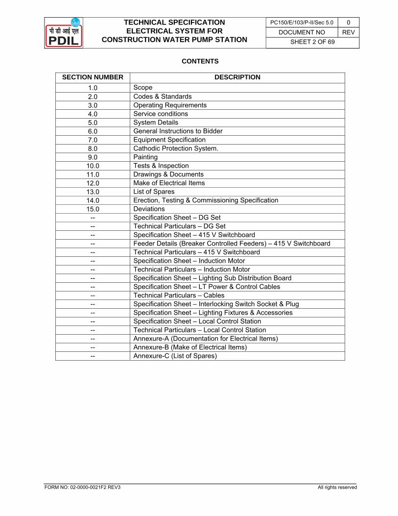
CONTENTS
SECTION NUMBER DESCRIPTION 1.0 Scope 2.0 Codes & Standards 3.0 Operating Requirements 4.0 Service conditions 5.0 System Details 6.0 General Instructions to Bidder 7.0 Equipment Specification 8.0 Cathodic Protection System. 9.0 Painting
10.0 Tests & Inspection 11.0 Drawings & Documents 12.0 Make of Electrical Items 13.0 List of Spares 14.0 Erection, Testing & Commissioning Specification 15.0 Deviations
-- Specification Sheet – DG Set -- Technical Particulars – DG Set -- Specification Sheet – 415 V Switchboard -- Feeder Details (Breaker Controlled Feeders) – 415 V Switchboard -- Technical Particulars – 415 V Switchboard -- Specification Sheet – Induction Motor -- Technical Particulars – Induction Motor -- Specification Sheet – Lighting Sub Distribution Board -- Specification Sheet – LT Power & Control Cables -- Technical Particulars – Cables -- Specification Sheet – Interlocking Switch Socket & Plug -- Specification Sheet – Lighting Fixtures & Accessories -- Specification Sheet – Local Control Station -- Technical Particulars – Local Control Station -- Annexure-A (Documentation for Electrical Items) -- Annexure-B (Make of Electrical Items) -- Annexure-C (List of Spares)
TECHNICAL SPECIFICATION ELECTRICAL SYSTEM FOR
CONSTRUCTION WATER PUMP STATION
PC150/E/103/P-II/Sec 5.0 0 DOCUMENT NO REV
SHEET 3 OF 69
FORM NO: 02-0000-0021F2 REV3 All rights reserved
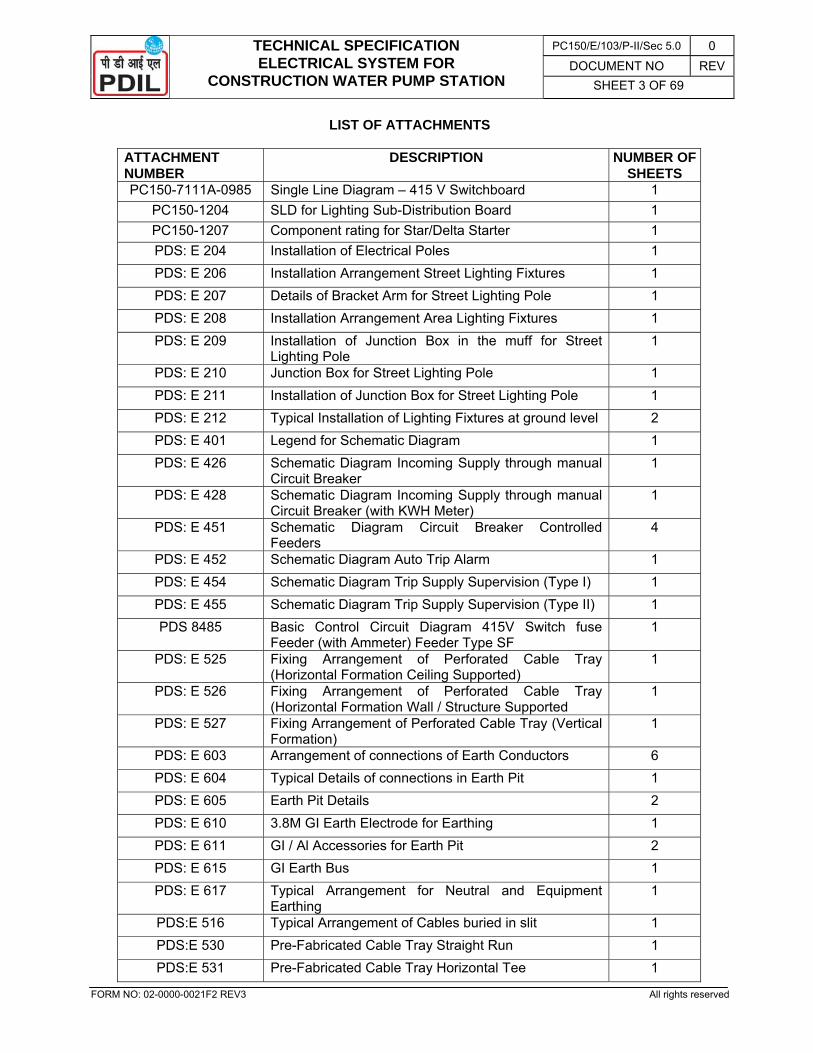
LIST OF ATTACHMENTS
ATTACHMENT NUMBER
DESCRIPTION NUMBER OF SHEETS
PC150-7111A-0985 Single Line Diagram – 415 V Switchboard 1 PC150-1204 SLD for Lighting Sub-Distribution Board 1 PC150-1207 Component rating for Star/Delta Starter 1 PDS: E 204 Installation of Electrical Poles 1 PDS: E 206 Installation Arrangement Street Lighting Fixtures 1 PDS: E 207 Details of Bracket Arm for Street Lighting Pole 1 PDS: E 208 Installation Arrangement Area Lighting Fixtures 1 PDS: E 209 Installation of Junction Box in the muff for Street
Lighting Pole 1
PDS: E 210 Junction Box for Street Lighting Pole 1 PDS: E 211 Installation of Junction Box for Street Lighting Pole 1 PDS: E 212 Typical Installation of Lighting Fixtures at ground level 2 PDS: E 401 Legend for Schematic Diagram 1 PDS: E 426 Schematic Diagram Incoming Supply through manual
Circuit Breaker 1
PDS: E 428 Schematic Diagram Incoming Supply through manual Circuit Breaker (with KWH Meter)
1
PDS: E 451 Schematic Diagram Circuit Breaker Controlled Feeders
4
PDS: E 452 Schematic Diagram Auto Trip Alarm 1 PDS: E 454 Schematic Diagram Trip Supply Supervision (Type I) 1 PDS: E 455 Schematic Diagram Trip Supply Supervision (Type II) 1 PDS 8485 Basic Control Circuit Diagram 415V Switch fuse
Feeder (with Ammeter) Feeder Type SF 1
PDS: E 525 Fixing Arrangement of Perforated Cable Tray (Horizontal Formation Ceiling Supported)
1
PDS: E 526 Fixing Arrangement of Perforated Cable Tray (Horizontal Formation Wall / Structure Supported
1
PDS: E 527 Fixing Arrangement of Perforated Cable Tray (Vertical Formation)
1
PDS: E 603 Arrangement of connections of Earth Conductors 6 PDS: E 604 Typical Details of connections in Earth Pit 1 PDS: E 605 Earth Pit Details 2 PDS: E 610 3.8M GI Earth Electrode for Earthing 1 PDS: E 611 GI / Al Accessories for Earth Pit 2 PDS: E 615 GI Earth Bus 1 PDS: E 617 Typical Arrangement for Neutral and Equipment
Earthing 1
PDS:E 516 Typical Arrangement of Cables buried in slit 1 PDS:E 530 Pre-Fabricated Cable Tray Straight Run 1 PDS:E 531 Pre-Fabricated Cable Tray Horizontal Tee 1
TECHNICAL SPECIFICATION ELECTRICAL SYSTEM FOR
CONSTRUCTION WATER PUMP STATION
PC150/E/103/P-II/Sec 5.0 0 DOCUMENT NO REV
SHEET 4 OF 69
FORM NO: 02-0000-0021F2 REV3 All rights reserved
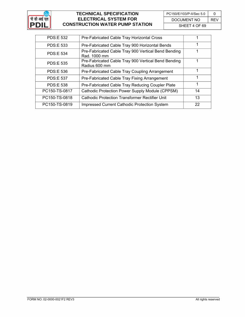
PDS:E 532 Pre-Fabricated Cable Tray Horizontal Cross 1
PDS:E 533 Pre-Fabricated Cable Tray 900 Horizontal Bends 1
PDS:E 534 Pre-Fabricated Cable Tray 900 Vertical Bend Bending Rad. 1000 mm
1
PDS:E 535 Pre-Fabricated Cable Tray 900 Vertical Bend Bending Radius 600 mm
1
PDS:E 536 Pre-Fabricated Cable Tray Coupling Arrangement 1
PDS:E 537 Pre-Fabricated Cable Tray Fixing Arrangement 1
PDS:E 538 Pre-Fabricated Cable Tray Reducing Coupler Plate 1 PC150-TS-0817 Cathodic Protection Power Supply Module (CPPSM) 14 PC150-TS-0818 Cathodic Protection Transformer Rectifier Unit 13 PC150-TS-0819 Impressed Current Cathodic Protection System 22
TECHNICAL SPECIFICATION ELECTRICAL SYSTEM FOR
CONSTRUCTION WATER PUMP STATION
PC150/E/103/P-II/Sec 5.0 0 DOCUMENT NO REV
SHEET 5 OF 69
FORM NO: 02-0000-0021F2 REV3 All rights reserved
1.0 SCOPE 1.1 The scope shall include design, engineering, manufacture, testing at works and delivery to site in
well packed condition, erection, testing and commissioning of complete Electrical System and Cathodic Protection System for Construction Water Pump Station to be installed at bank of Brahmani River.
1.2 This specification shall be read in conjunction with all standards, Data sheets and other relevant reference as specified herein.
1.3 The scope shall include but not limited to the following:
- DG Set
- Drive motors for the pump.
- Local Control Stations
- 415 V Switchboard
- Lighting Sub Distribution Board.(LSDB)
- Cable from DG to 415 V Switchboard; 415V Switchboard to Motors, LSDB and Switch Socket; LSDB to Lighting Fixtures/ Switch Sockets etc.
- Lighting System
- Earthing System
- Cathodic Protection System
- All other items not specified but required for safe and proper operation.
1.4 The scope shall also include the erection, testing, commissioning of above equipments.
The contractor shall arrange all the necessary erection tools, tackles, testing and measuring instruments and shall supply erection materials and consumables.
The contractor shall clear the site after commissioning of the equipments / system and obtain the Site Clearance Certificate from owner’s Engineer-in-charge
1.5 The scope of work shall also include digging of earth and refilling for directly buried cables, earth strips, cable protection pipes, earth pits, ground mounted lighting pole foundations; civil works such as making earth pit inspection chambers with covers, grouting of equipment base plate, channels, supports and foundation bolts, chipping of concrete or in brick work for earth strips, pipes or other minor chipping for foundation preparation, if required, cutting holes in walls for racks, risers, light fitting brackets, sealing of cable entries and making good the same after installation of the equipment and levelling, and other minor similar jobs as per directions of Owner / Engineer-in-Charge.
1.6 All major Civil work (like making all foundations and cable trenches etc) and minor civil work (like cutting, chipping, grouting, making opening in floor / wall etc. for equipment foundation and cabling work) pertaining to electrical equipment are in the scope of work of the contractor and shall be done as per technical specification of civil enclosed elsewhere in the NIT.
1.7 The contractor shall obtain the necessary clearance from Electrical Inspector of Odisha for complete electrical installation, as well as Odisha State Pollution Control board, as required. All necessary drawings, calculations, test certificates and record of site tests etc. as required by the Inspector shall be furnished. Any modification / rectification as required by Electrical Inspector / Odisha State Pollution Control Board shall be carried out free of cost by the contractor. However, necessary statutory fee shall be deposited by the owner.
TECHNICAL SPECIFICATION ELECTRICAL SYSTEM FOR
CONSTRUCTION WATER PUMP STATION
PC150/E/103/P-II/Sec 5.0 0 DOCUMENT NO REV
SHEET 6 OF 69
FORM NO: 02-0000-0021F2 REV3 All rights reserved
2.0 CODES & STANDARDS 2.1 The design, manufacture and testing of the equipment shall comply with the latest issue of
relevant Indian Standard specification and codes of practices / relevant IEC.
2.2 The design and operational features of the equipment offered shall also comply with the provisions of latest issue of the Indian Electricity Rules and other relevant Statutory Rules & Regulations. The supplier shall, whenever necessary, make suitable modification in the equipment to comply with the above mentioned rules.
2.3 Wherever any requirement, laid down in this Technical specification / Specification Sheet, differs from that in IS, the requirements specified in this specification / Specification Sheets shall prevail.
3.0 OPERATING REQUIREMENTS 3.1 All equipment and accessories shall be suitable for trouble free and continuous service at their
rated capacity in the specified ambient and system conditions.
4.0 SERVICE CONDITIONS 4.1 The equipment shall be designed for the following site conditions :
• Minimum ambient Temperature : 1 deg.C
• Maximum ambient Temperature : 46 deg.C
• Design Reference Temperature : 50 deg.C
• Relative Humidity : 100%
• Altitude above mean sea level : Lower than 1000 Mtrs.
• Atmospheric pollution : Humid & Dusty and corrosive .
5.0 SYSTEM DETAILS - Power from DG Set : 415 V ± 5%, 50Hz ± 3%, 3Ph, 3 W (DG shall be in Contractor’s scope)
5.1 The equipment shall be suitable for the system details as specified and respective clauses of this specification.
6.0 GENERAL INSTRUCTIONS TO BIDDER
6.1 .The electrical equipment shall be designed as per latest practice to provide maximum reliability, flexibility, safety to personnel and equipment and ease of operation and maintenance.
6.2 All equipment shall have adequate and standard ratings.
6.3 Power shall be provided by DG of suitable rating.
6.4 Bidder shall must visit the site and collect all relevant information required for designing of complete system before quoting.
6.5 The 415V switchboard, Lighting Sub Distribution board, Cathodic Protection Equipment etc. shall be placed in the existing substation.
6.6 DG Set
6.6.1 DG set shall be suitably rated for starting of the Pump motors as well as catering lighting load of approx. 2 KVA, etc. Bidder shall submit sizing calculation of DG rating along with the bid.
6.6.2 The bidder shall guarantee “fuel consumption” of the DG set. The offer shall be evaluated considering capitalisation of the Operating Cost for which Net Present Value (NPV) method, as given below, shall be adopted:
NPV of Operating Cost = A x B x C x H x 2.48
Where,
TECHNICAL SPECIFICATION ELECTRICAL SYSTEM FOR
CONSTRUCTION WATER PUMP STATION
PC150/E/103/P-II/Sec 5.0 0 DOCUMENT NO REV
SHEET 7 OF 69
FORM NO: 02-0000-0021F2 REV3 All rights reserved
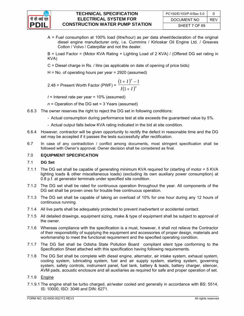
A = Fuel consumption at 100% load (litre/hour) as per data sheet/declaration of the original diesel engine manufacturer only, i.e. Cummins / Kirloskar Oil Engine Ltd. / Greaves Cotton / Volvo / Caterpillar and not the dealer.
B = Load Factor = (Motor KVA Rating + Lighting Load of 2 KVA) / (Offered DG set rating in KVA)
C = Diesel charge in Rs. / litre (as applicable on date of opening of price bids)
H = No. of operating hours per year = 2920 (assumed)
2.48 = Present Worth Factor (PWF) = ( )( )n
n
III+
−+1
11
I = Interest rate per year = 10% (assumed)
n = Operation of the DG set = 3 Years (assumed)
6.6.3 The owner reserves the right to reject the DG set in following conditions:
- Actual consumption during performance test at site exceeds the guaranteed value by 5%.
- Actual output falls below KVA rating indicated in the bid at site condition.
6.6.4 However, contractor will be given opportunity to rectify the defect in reasonable time and the DG set may be accepted if it passes the tests successfully after rectification.
6.7 In case of any contradiction / conflict among documents, most stringent specification shall be followed with Owner’s approval. Owner decision shall be considered as final.
7.0 EQUIPMENT SPECIFICATION 7.1 DG Set 7.1.1 The DG set shall be capable of generating minimum KVA required for (starting of motor + 5 KVA
lighting loads & other miscellaneous loads) (excluding its own auxiliary power consumption) at 0.8 p.f. at generator terminals under specified site condition.
7.1.2 The DG set shall be rated for continuous operation throughout the year. All components of the DG set shall be proven ones for trouble free continuous operation.
7.1.3 The DG set shall be capable of taking an overload of 10% for one hour during any 12 hours of continuous running.
7.1.4 All live parts shall be adequately protected to prevent inadvertent or accidental contact.
7.1.5 All detailed drawings, equipment sizing, make & type of equipment shall be subject to approval of the owner.
7.1.6 Whereas compliance with the specification is a must, however, it shall not relieve the Contractor of their responsibility of supplying the equipment and accessories of proper design, materials and workmanship to meet the functional requirement and the specified operating condition.
7.1.7 The DG Set shall be Odisha State Pollution Board compliant silent type conforming to the Specification Sheet attached with this specification having following requirements.
7.1.8 The DG Set shall be complete with diesel engine, alternator, air intake system, exhaust system, cooling system, lubricating system, fuel and air supply system, starting system, governing system, safety controls, instrument panel, fuel tank, battery & leads, battery charger, silencer, AVM pads, acoustic enclosure and all auxiliaries as required for safe and proper operation of set.
7.1.9 Engine
7.1.9.1 The engine shall be turbo charged, air/water cooled and generally in accordance with BS: 5514, IS: 10000, ISO: 3046 and DIN: 6271.
TECHNICAL SPECIFICATION ELECTRICAL SYSTEM FOR
CONSTRUCTION WATER PUMP STATION
PC150/E/103/P-II/Sec 5.0 0 DOCUMENT NO REV
SHEET 8 OF 69
FORM NO: 02-0000-0021F2 REV3 All rights reserved
7.1.9.2 The engine shall consist of the following items/components:
i. Heavy duty radiator with guard and water circulating pump (in case of water cooled engine)
ii. Air blowing fan of high performance for giving efficient cooling
iii. Engine flywheel, if required, with starter ring and guard
iv. Flexible coupling, suitable to match flywheel, with safety guard
v. 12 V DC starting system complete with battery, battery charger, electric starter and battery charging alternator.
vi. Mechanical/electronic governor
vii. Fuel Pump/ Fuel Solenoid
viii. Lube Oil Pump
ix. Fuel & Lube oil filters (paper element type)
x. Lube Oil cooler
xi. Air cleaner, dry type/ oil bath type
xii. Flexible pipe silencer with necessary flanges.
xiii. Suitable Turbo charger, driven from exhaust gas
xiv. In-built safety controls against Low lube oil Pressure, High cooling water temperature (in case of water cooled engine), High cylinder head temperature and Engine Over speed with automatic shutdown.
xv. Standard fuel tank of 24 hours continuous running of the engine. Filling up of diesel shall be by Hand Pump from the standard drums. The fuel oil tank shall be suitably located in the base of the acoustic enclosure to provide absolute safety, protection and long hours of uninterrupted and continuous power. The fuel tank shall be compatible with the State Pollution Control Board approved acoustic enclosure. Special fuel gauge shall be provided for monitoring the fuel level.
7.1.9.3 The instrument panel to be mounted on the DG set skid shall consist of the following control and monitoring provisions:
i. Start / stop key switch / Push buttons
ii. Lube oil pressure indication
iii. Low lube oil trip indication
iv. Water temperature indication (for water cooled engine)
v. High water temperature trip indication (for water cooled engine)
vi. Engine Speed (RPM) indication
vii. Over speed trip indication
viii. Operation hour counter
ix. Battery charging indication
7.1.10 Alternator
7.1.10.1 The alternator shall be of the manufacturer's standard design.
7.1.10.2 The rating of the alternator shall be net output at the specified ambient conditions (i.e. rating after allowing the derating, as applicable for the stipulated site conditions).
TECHNICAL SPECIFICATION ELECTRICAL SYSTEM FOR
CONSTRUCTION WATER PUMP STATION
PC150/E/103/P-II/Sec 5.0 0 DOCUMENT NO REV
SHEET 9 OF 69
FORM NO: 02-0000-0021F2 REV3 All rights reserved
7.1.10.3 Excitation shall be of brushless type and shall have rating of at least 110% of what is required when the alternator is operating at full speed. The stator, rotor and exciter shall have class “F” insulation with maximum temperature rise as allowed for class B.
7.1.10.4 The alternator shall be provided with automatic voltage regulator which will maintain the static voltage of the alternator within specified limits at all loads and the power factor between 0.8 and 1.0.
7.1.10.5 Space heater rated for 240V AC shall be provided to keep winding dry during idle periods.
7.1.10.6 The alternator shall be designed for direct coupling with the engine.
7.1.10.7 The alternator with its exciter shall be totally enclosed air cooled and suitable for IP23 protection as per IS: 4691.
7.1.10.8 Rolled aluminium or Nickel/Cadmium plated brass, heavy duty, double compression type cable glands, shall be mounted on removable gland plate.
7.1.11 Starting System
7.1.11.1 Electrical starting system shall be provided, which shall be comprise of starter motor, battery, battery charger and required cabling, instruments and accessories.
7.1.11.2 The battery shall be of 12 V, 100 AH, automotive lead acid type suitable for 3 successive starting attempts.
7.1.11.3 The starting system shall be such that the DG set shall start and come to rated speed and ready to accept full load within the period specified in the DG set Specification Sheet.
7.1.12 Earthing system
7.1.12.1 Neutral earthing and equipment earthing shall be done as per IS: 3043. Neutral of alternator shall be earthed through 2 Nos. 1.1 KV PVC insulated, unarmoured PVC sheathed 1Cx50 sq. mm aluminium or equivalent size of copper conductor cable and brought to 2 Nos. earth pits outside the enclosure. Bodies of all the electrical equipments shall be earthed through proper size of earthing conductors and brought to a common earth bus mounted inside the acoustic enclosure. 2 nos. 50x6 G.I. earthing strips from this earth bus shall be brought out of the enclosure for connection to existing earth grid outside the enclosure. Thus 2 Nos. earth pits comprising of concrete chamber, CI cover, plate electrodes, GI pipe, funnel, wire mesh and all other accessories and fixing hardware along with all required sizes of earthing conductors shall be in contractor’s scope. These 2 Nos. earth pits shall be interconnected with each other and also with the owner’s earth grid at 2 points through 50x6 G.I. earthing strips.
7.1.13 Acoustic Enclosure
7.1.13.1 The acoustic enclosure shall be of modular construction and made of minimum 16 SWG thick cold rolled sheet steel.
7.1.13.2 The enclosure, after suitable pre-treatment, shall be painted with two coats of antirust paint followed by two coats of anticorrosive epoxy based paint.
7.1.13.3 All external hardware shall be of stainless steel.
7.1.13.4 The enclosure shall be provided with external drain plug for drain lube oil and fuel.
7.1.13.5 The doors shall be provided with quality EPDM gaskets to prevent leakage of sound.
7.1.13.6 The door handles shall be lockable type.
7.1.13.7 Sound proofing of the enclosure shall be done with high quality rock wool/mineral wool conforming to IS: 8183. The rock wool shall be further covered with fibre glass tissue and perforated sheet.
7.1.13.8 Special silencer shall be provided within the enclosure to reduce exhaust noise.
7.1.13.9 Specially designed attenuators shall be provided to control sound at air entry and exit points.
TECHNICAL SPECIFICATION ELECTRICAL SYSTEM FOR
CONSTRUCTION WATER PUMP STATION
PC150/E/103/P-II/Sec 5.0 0 DOCUMENT NO REV
SHEET 10 OF 69
FORM NO: 02-0000-0021F2 REV3 All rights reserved
7.1.13.10 Adequate ventilation shall be provided to meet total air requirement. If required, a blower shall be provided to meet total air requirement.
7.1.13.11 Temperature of the enclosure shall not exceed beyond 5oC of ambient temperature.
7.1.13.12 There shall be a provision of emergency shutdown of the DG Set from outside the enclosure.
7.1.13.13 The enclosure shall be provided with internal illumination.
7.1.13.14 The enclosure shall be provided with control panel viewing window.
7.1.13.15 Noise level shall not exceed 75 dB(A) at one metre distance from the enclosure.
7.1.13.16 Tested and certified adequate lifting facilities shall be provided. Lifting points shall be provided on the base frame.
7.2 Motors 7.2.1 Motors shall conform to IS: 325 and Specification Sheet enclosed.
7.2.2 Motor shall be suitable for Star/Delta starting on full load.
7.2.3 The motor (frame sizes from 71 up to and including 315L) shall be energy efficient type having efficiency class of ‘IE2’ as per IS 12615: 2011 and high power factor type.
7.2.4 The rating of the motor shall be as per the sizes in the ISS. The margin between the installed power and absorbed power shall not be less than the following:
Motor Rating Margin above Driven M/C Absorbed Power
Less than 22 KW 25%
22 KW to 55 KW 15%
75 KW and above 10%
7.2.5 The duty cycle of the motor shall meet the process and driven machine requirement.
7.2.6 Voltage rating for the motors of different KW ratings shall be as below:
Up to 150 KW : 415V, 3-phase, 50 Hz AC
7.2.7 The rotor shall be of squirrel cage cylindrical type construction. The rotor shall be made of laminated steel with good electrical performance.
7.2.8 The cooling fans shall be suitable for bidirectional rotation of motors. These shall be fastened to the motor shaft by means of compensating rings or will be balanced independent of the motor. Guide key or reference points shall be supplied to prevent wrong assembly. The cooling air shall be sucked from the non-driving end.
7.2.9 All motors shall be provided with bearings suitable for the application. The bearings must be guaranteed to ensure a smooth operation and a life not shorter than 40,000 hrs.
7.2.10 The bearing shall be suitable for both directions of rotation of the motor.
7.2.11 Motor terminal box shall be designed to rotate at 90° at site.
7.2.12 For all vertical flange mounted motors, the limitations on shaft extension, run out, perpendicularity and eccentricity, as required by the driven machine supplier shall be complied with by the motor supplier.
7.2.13 Space heaters rated for 240 V A.C. shall be provided to keep the winding dry for all motors, except for motors rated below 30 KW.
7.2.14 Motors for outdoor service shall be provided with special seals for the enclosure, joints, bearing housing, terminal boxes etc. so that no extra protective covering for ingress of water shall be required.
7.2.15 Vertical motors for outdoor installation shall be provided with a rain protective hood.
TECHNICAL SPECIFICATION ELECTRICAL SYSTEM FOR
CONSTRUCTION WATER PUMP STATION
PC150/E/103/P-II/Sec 5.0 0 DOCUMENT NO REV
SHEET 11 OF 69
FORM NO: 02-0000-0021F2 REV3 All rights reserved
7.2.16 All external hardware shall be made of stainless steel SS-304/316.
7.2.17 The motor noise level shall not exceed 85 dB measured at a distance of 1 metre from the motor.
7.2.18 The motor vibrations measured at the bearings must not exceed the limits specified in IS: 12075, unless otherwise stipulated in the specification sheet.
7.2.19 All terminal boxes of motor as well as starter shall be complete with heavy duty rolled Aluminium double compression type cable glands and lugs/connectors to receive the external cables.
7.2.20 Specification Sheet duly filled in with balance data for motors shall be furnished with bid.
7.2.21 Filled in Technical Particulars of motors shall be furnished by the Contractor for approval after order in line with ITB/PO requirement before commencement of manufacturing.
7.3 Local Control Stations
7.3.1 Local Control Stations shall be provided for all motors.
7.3.2 Each LCS shall have provisions as indicated in specification sheet of LCS.
7.3.3 The enclosure for LCS shall be of Die cast Aluminium alloy/ Fibre Glass Reinforced Polyester and shall be flameproof & weatherproof construction. Rain hood fabricated out of 14 SWG Aluminium sheet shall be provided as an additional protection. The enclosure shall be suitable for mounting on wall or on steel structure. 4 Nos. holes suitable for 12 mm bolts shall be provided outside the enclosure for fixing the control stations.
7.3.4 Provision for pad locking shall be provided.
7.3.5 Trip-Neutral-Close control switch shall be three position control switch with spring return from CLOSE to NEUTRAL position and lockable in TRIP position by means of padlock.
7.3.6 The switches shall have sliding contact between ’NEUTRAL’ and ‘CLOSE’ position. In ‘TRIP’ position the contact shall be completely broken from ‘NEUTRAL’ position.
7.3.7 Local control stations for contactor controlled LV motors shall be provided with start/stop push buttons and ammeters shall be provided for the motors having rating 5.5 KW and above.
7.3.8 Each element for start and stop shall be provided with 1 NO + 1 NC contact. The push button construction shall be such to avoid mal-operation due to vibrations.
7.3.9 The ammeter shall be flush mounting, moving iron spring controlled type, of accuracy class 1.5 as per IS: 1248, with square face of minimum size 72 mm × 72 mm having scale range 0-90 degree. The ammeter shall be provided with uniform scale up to CT primary current and compressed end scale up to the 6 times the C.T. primary current. Adjustable red pointer shall be provided to indicate the full load current of the motors. Zero adjusters shall be provided for operation from the front of the meter. All ammeters shall be operated through 1 Amp. CTs only.
.All local control stations shall have weather proof IP-65 enclosure as per IS: 13947 suitable for outdoor location. The enclosure shall be of die cast Aluminium alloy LM-6. As an alternative to cast Aluminium, fibre glass enclosure is also acceptable. Canopies of suitable size shall be provided with all local control stations.
7.3.10 The enclosure shall be provided with two external earthing terminals with studs of 8 mm. dia. and shall be marked with earthing symbol. LCS shall be painted with epoxy paint to shade 631 as per IS : 5.
7.3.11 The control stations shall be completely factory wired and ready for external cable connection.
7.3.12 Each control station shall be provided with minimum 2 mm thick stainless steel nameplates indicating the code number and description of the equipment controlled by it. Similar labels shall be provided for all indication lamps, push buttons, control switches. The nameplate and label shall be fixed with screws only.
TECHNICAL SPECIFICATION ELECTRICAL SYSTEM FOR
CONSTRUCTION WATER PUMP STATION
PC150/E/103/P-II/Sec 5.0 0 DOCUMENT NO REV
SHEET 12 OF 69
FORM NO: 02-0000-0021F2 REV3 All rights reserved
7.4 415 V SWITCHBOARDS 7.4.1 415 V switchboards shall be metal clad floor mounted type, arranged with self supporting units
and assembled together in a row. 415V Switchboard shall also conform to the specification sheet (attached in this specification) Rated short circuit breaking capacity for 415V switchboard shall be minimum 50 KA for 1 sec.
7.4.2 Switchboard shall conform to IEC 60947.
7.4.3 Switchboard shall be fixed type. The attached Single diagram is indicative and components ratings etc. shall be decided based on motors rating, DG rating etc.
7.4.4 The complete assembly shall be dust, dam and vermin proof having minimum degree of protection IP-52.
7.4.5 A suitable barrier shall be provided between the switching equipment and the associated control, protective and indication devices including instrument transformers.
7.4.5.1 The bus-bars shall be amply sized to carry the rated continuous current under the specified ambient temperature without exceeding the limits specified in IS: 8084. The thermal rating of the bus-bars shall be designed to withstand 50kA for 1 second without exceeding the limiting temperature.
7.4.5.2 The main bus bars of switchboards shall have heat shrinkable insulated sleeves suitable for rated voltage and shall be made of high conductivity electrolytic copper. At joints of these busbars removable shrouds shall be provided.
7.4.6 Horizontal bus-bars shall run in a separate compartment through the entire length of the board and shall be of same cross-section throughout. Stepped bus-bars shall not be acceptable.
7.4.7 Bus bars shall be supported on non-hydroscopic FRP insulators with adequate clearances and creepage distance to prevent flash over due to effect of dust/moisture.
7.4.8 Sufficient bus supports shall be given to give adequate mechanical strength during short circuits.
7.4.9 Busbar clearances shall conform to relevant Indian Standard/IEC for equipment voltages up to and including 500 V AC.
7.4.10 The clearances and creepage distances shall not be lower than the values specified below:
i) Minimum clearance between two live conductors - 20 mm
ii) Minimum clearance between live parts and accidentally dangerous part - 20 mm
iii) Minimum creepage distance - 28 mm
7.4.11 A continuous ground bus shall be provided at the bottom of the switchgear and in cable connection side for grounding the switchgear, cable glands.
7.4.12 Adequate arrangement for earthing shall be provided to safeguard the operator or other personnel from electric hazards under all conditions of operation.
7.4.13 The minimum size of module shall be 200 mm for switch fuse feeders.
7.4.14 The minimum clear width of cable alley shall be 250 mm.
7.4.15 The minimum thickness of sheet steel used in LV switchgear shall be as under:-
a) Base Channel minimum 3.0 mm
b) Load Bearing Members minimum 2.0 mm
c) Doors and covers minimum 1.6 mm
TECHNICAL SPECIFICATION ELECTRICAL SYSTEM FOR
CONSTRUCTION WATER PUMP STATION
PC150/E/103/P-II/Sec 5.0 0 DOCUMENT NO REV
SHEET 13 OF 69
FORM NO: 02-0000-0021F2 REV3 All rights reserved
7.4.16 Every enclosure door that provides access to live parts operating at 240 V AC and above shall be mechanically interlocked with a circuit interrupting device on the supply side such that when the door is open, the equipment is de-energised.
7.4.17 Mounting height of components requiring operations and observation shall not be lower than 300 mm and higher than 1800 mm.
7.4.18 All live parts which are accessible after opening of front and back door/cover shall be properly insulated or provided with insulating barrier to prevent accidental contact. Phase insulating barriers shall be provided between the poles. Removal facility shall be provided for all such barriers.
7.4.19 All external hardware shall be cadmium plated. The hardware for fixing the removable parts shall be provided with retaining devices.
7.4.20 The doors and the removable covers shall be provided with non-deteriorating neoprene gaskets. Gaskets without any discontinuity shall be preferred. Gaskets shall be held in position in groove, in shaped sheet steel work or these shall be of U type.
7.4.21 All the components shall be accessible for inspection and maintenance without the necessity of removing the adjacent ones. Their mounting shall be accessible and ensure the necessary degree of safety.
7.4.22 Star-Delta starter shall be used for all motors as specified in Single line diagram. The starter shall have contactors, electronic timer, Thermal overload relay with SPP, overload hand reset PB, Start PB, Stop PB (stay-put device for off device), ON, OFF and Trip indicating lamp, one no. auxiliary contactor (2 NO + 2 NC), current transformers, earth leakage relay etc.
Rating of various components in Star/Delta Starter shall be as per Component rating for Star/Delta Starter (Doc. No. PC150-1207).
In case of ACB as switching component for motor feeders, microprocessor based numerical relay shall be provided. Other components of motor feeder shall be as indicated in Single Line Diagram and Feeder Details. For Star/Delta starter, Contactors, timer etc. shall be provided.
7.4.23 Incomer feeder shall have components as indicated in Single Line Diagram and Feeder Details.
7.4.24 Air Circuit Breaker
Air circuit breakers shall comply with the requirement of IS/IEC 60947.
All circuit breakers shall be of P2 (O-0.3sec-CO-3min-CO) category, capable of carrying the specified current at the site conditions and making/breaking of the system fault current.
Type test certificates from an independent testing authority shall be furnished along with the offer for each circuit breaker rating and type.
The Air circuit breakers shall be of the 3 phase, 4 pole (for Incomer) / 3 pole (for motors) horizontal draw out, horizontal isolation, air break type.
The circuit breaker shall be suitable for electrical or manual closing as specified. Manual operated breakers shall have independent manual spring closing mechanism. In case of electrically operated breaker, it shall have motor wound spring mechanism. In all cases tripping shall be by means of shunt trip coil.
All circuit breaker units of the same rating shall be physically and electrically interchangeable.
The circuit breakers shall be electrically and mechanically trip free and provided with anti-pumping feature.
TECHNICAL SPECIFICATION ELECTRICAL SYSTEM FOR
CONSTRUCTION WATER PUMP STATION
PC150/E/103/P-II/Sec 5.0 0 DOCUMENT NO REV
SHEET 14 OF 69
FORM NO: 02-0000-0021F2 REV3 All rights reserved
Provision shall be made for slow closing for maintenance purposes. A suitable handle shall be provided one for each board for this purpose.
The circuit breakers shall have three positions i.e. service, test and isolated with the cubicle door closed. Necessary stoppers shall be provided to prevent the excessive movement of the breaker cradle than desired for the position. Service and test positions of the breaker shall have monitoring switch having 1NO+1NC contacts.
The circuit breaker shall be provided with emergency manual trip device, mechanical ‘ON’, ‘OFF’ and ‘ISOLATED’ position indicators and operation counter.
A maintenance truck/device for raising, lowering and withdrawal of the circuit breaker shall be supplied for each switch board.
The arc interrupting devices shall be capable of interrupting satisfactorily current from zero to the rated interrupting current when used on predominantly capacitive or inductive circuits, without requiring excessive maintenance of the contacts. The arc shall be restricted within the interrupting chamber and no emission of flame shall be allowed which may cause electrical breakdown or damage to insulation on the apparatus.
The main contacts shall be self aligning, adjustable and replaceable type.
The arcing contacts shall be easily accessible for maintenance and inspection and shall be easily replaceable type. They shall be provided with, contact face of special arc-resisting and non-pitting metal.
Mechanical safety interlock shall be provided for safe operation and movement of the breaker.
The circuit breakers shall be provided with minimum of four normally open and four normally closed auxiliary switch contacts, over and above those required for its own control scheme, for Owner’s use. The contacts shall be wired separately to the terminal board.
The closing coil and other associated auxiliary relays shall operate satisfactorily at all voltages between 85% and 110% of the rated control voltage. The tripping coil and other associated relays shall operate satisfactorily at all voltages between 70% and 110% of the rated control voltage.
Cable earthing facility shall be provided in the circuit breaker for discharging of power cable through the circuit breaker contact with circuit breaker in drawn-out position. An integral earthing arrangement shall be preferred. In case the integral earthing arrangement is not feasible due to circuit breaker design, a separate earthing truck, which shall be inserted in place of circuit breaker, shall be provided per board.
Positive earthing of circuit breaker frame shall be maintained at every position of circuit breaker. The earthing contact shall be line/scrapping type and not of point type
7.4.25 Switches
The switches shall be motor duty type AC 23 Category and shall comply with the requirements laid down in IS/IEC 60947. Switches up to 63 Amps shall be rotary type and those of 100 Amps. & above, link type.
‘ON’ and ‘OFF’ position of the switches shall be indicated on the module. Provision shall be made to lock the switch in the ‘OFF’ position.
The fixed contacts shall be shrouded type. All contacts shall be silver plated.
7.4.26 Fuses
The fuses shall be of non-deteriorating HRC cartridge link type and shall conform to IS: 13703. They shall be suitable for the load and service required in the circuit.
TECHNICAL SPECIFICATION ELECTRICAL SYSTEM FOR
CONSTRUCTION WATER PUMP STATION
PC150/E/103/P-II/Sec 5.0 0 DOCUMENT NO REV
SHEET 15 OF 69
FORM NO: 02-0000-0021F2 REV3 All rights reserved
One fuse puller shall be supplied.
7.4.27 Contactors
The Contactor shall be air break, double break single throw, and electromagnetic type of Category AC3/AC4, unless otherwise specified, conforming to IS: 60947 and flapper type.
Main contacts shall be of silver faced copper
The dropout voltage shall not exceed 65% of rated voltage.
Minimum two NO and two NC auxiliary contacts shall be provided for each power contactor. The rating of the auxiliary contacts shall be 5 Amps. AC at the control voltages. The spare auxiliary contacts shall also be wired up to the terminal blocks.
7.4.28 Bimetal Thermal Overload Relays
The contactor shall be provided with three pole bimetal thermal overload relays, unless other-wise specified. The bimetal relays shall be of suitable range, ambient temperature compensated and shall be separate mounting type. They shall be adjustable through graduated scale and shall be provided with changeover contact. Thermal relays having long time/current characteristics, operated through saturated C.T.s shall be supplied, wherever required.
Bimetal thermal relays shall conform to IS: 3231 and IS/IEC 60947 and shall have built-in single phasing preventor.
The bimetal relays shall be provided with a manual resetting device resettable after opening module door. Auto reset thermal relays are not acceptable
7.4.29 Current Transformers
C.T.s shall be class F insulated and vacuum impregnated or resin cast type and shall conform to IS: 2705. The C.T.s shall be rigidly mounted and shall be easily accessible for maintenance and testing.
The C.T.s output shall be minimum 15 VA per phase and in any case, the output shall be adequate for the protection and metering duties involved with sufficient margin. The C.T.s shall have the following accuracies for the various applications:
Application Class of Accuracy as per IS: 2705
i) For metering service 1
ii) For use with protective relays 5 P
The C.T. cores for metering and protection shall be separate.
7.4.30 Voltage Transformers
The V.T.s shall be class F insulated and vacuum impregnated or resin cast type conforming to IS: 3156
The rated output of each VT shall be adequate for the relays, meters and associated wiring connected to it with sufficient margin and shall not be less than 50VA per phase for LV Switchboard.
The accuracy class of V.T.s shall be 1 as per IS: 3156.
7.4.31 Timers The timers shall be electronic type with manual/auto reset features as per the functional requirements. The time delay shall be ‘ON’ delay or ‘OFF’ delay type as required. The repeat accuracy shall be 0.5% or better.
TECHNICAL SPECIFICATION ELECTRICAL SYSTEM FOR
CONSTRUCTION WATER PUMP STATION
PC150/E/103/P-II/Sec 5.0 0 DOCUMENT NO REV
SHEET 16 OF 69
FORM NO: 02-0000-0021F2 REV3 All rights reserved
7.4.32 Single Phasing Preventor
Single phasing preventor relay shall be of the current operated type, suitable for the system voltage. The relay shall not operate for normal system voltage but operate positively in the event of unbalanced voltage more than the normal. The relay shall not operate in case of total interruption of power.
The relay shall be fail safe, self reset type and provided with flag indication. The relay operation shall be independent of the motor rating, loading and speed.
7.4.33 Instruments and Meters
All instruments shall be flush mounting type with square face of 96 mm x 96 mm. They shall be tropicalized and dust tight.
All ammeters and voltmeters, to be provided separately, shall have 0-90º scale and shall be moving iron spring controlled type of class 1.5 accuracy as per IS: 1248. The scale range of the ammeters and voltmeters shall be as indicated in the Feeder details.
In case of motor feeders, the ammeters shall be graduated uniformly upto C.T. primary current and with compressed end scale upto 6 times C.T. primary current. Red pointer shall be provided, which shall be adjusted at site for indicating full load current of the motor.
7.4.34 Push Buttons and Control Switches
The switches and push buttons shall conform to utilization category AC11/DC11 as per IS: 60947. The contact shall be rated to make, break and carry inductive current of 5 Amp at 415 V AC.
The selector switches shall be stay put rotary type and provided with oval shape handles.
The push buttons shall be of momentary contact spring loaded type with a set of normally close and open contacts. The push button for ‘Start’ shall be shrouded type and coloured green, stop push button shall be un-shrouded type and coloured red and other push buttons shall be un-shrouded type coloured black. The fixing ring shall be metallic white.
Push buttons for checking the healthiness of indication lamps in all feeders shall be provided.
7.4.35 Miniature Circuit Breakers
The miniature circuit breakers shall conform to IS: 8828 and shall be of duty category M-9.
It shall be provided with overload and short circuit protective devices in a heat resistant housing.
7.4.36 Signal Lamps
Signal lamps shall be provided to indicate the various circuit conditions as shown in scheme drawings. The colour of the lamps for various functions shall be as follows :
Red -- switch/contactor closed.
Green -- switch/contactor open.
Indication lamp shall be LED type with LVGP protection having good illumination in all direction with lumen output of minimum 200milli Candela +/-10%.
7.4.37 The wiring shall be carried out with flexible stranded PVC insulated copper conductor cables of 1100 Volt grade. The minimum size of wires shall be as follows:
C.T. Circuit -- 2.5 Sq. mm
V.T. and Control Circuits -- 1.5 Sq. mm
7.4.38 Auxiliary AC power is to be tapped from the feeder itself.
TECHNICAL SPECIFICATION ELECTRICAL SYSTEM FOR
CONSTRUCTION WATER PUMP STATION
PC150/E/103/P-II/Sec 5.0 0 DOCUMENT NO REV
SHEET 17 OF 69
FORM NO: 02-0000-0021F2 REV3 All rights reserved
7.4.39 Name plate shall be of Aluminium / black Perspex with white engraving and of minimum 3 mm thick.
7.4.40 Contractor to submit the schematic diagram for switchboards for owner/consultant approval before commencement of manufacturing.
7.4.41 Fire retardant / extinguishing Elect. Insulated Synthetic Mat suitable for 3.3 kV voltage grade having nominal thickness of 2.0mm ± 10%, Electrically insulated PVC synthetic sheet along with suitable Resin/ Chemical bound (Hardener)/ Adhesive /Pigment/ PVC Strip etc & having minimum current leakage as per IS shall be provided in front of switchboard, LSDB and Changeover switch. Mats shall conform to BIS: DOC NO. ET-02 (5440) Dt.30/04/04, meet requirements of IS 15652:2006, 5216 (part-1, 2&3), IS 8437, IS 3043 & IEC 479 Pub-1 & tested for Tensile/ Elongation properties, Insulation Resistance, effects of Acid Alkaline Diesel & Transformer Oil, Leakage Current Test, Fire Test etc.
7.5 Lighting Sub Distribution Board 7.5.1 LSDB shall be provided with incoming and outgoing feeders as indicated SLD attached with this
specification and specification sheet (attached in this specification) having IP-65 degree of protection.
7.5.2 Incomer feeder shall be provided with 63A TP and Switched Neutral SFU and 3 nos. feeder circuit of 63A DP MCB having 9 Nos. outgoing of 16 A/25 A DP MCB (i.e. 3 nos. 16 A/ 25 A DP MCB per circuit).
7.5.3 The enclosure for LSDB shall be fabricated out of 2.5 mm thick cold rolled sheet steel having dust, vermin and weatherproof construction conforming to IP54 as per IS: 13947. 4 nos. holes suitable for 12mm bolts shall be provided outside the enclosure for fixing the LSDB.
7.5.4 The miniature circuit breakers (MCBs) shall be so mounted inside the enclosure that their operating knobs project outside for ease of operation. The cut out for the knobs on the enclosure shall be lined with gaskets. For further protection against ingress of dust, the portion where the knobs have protruded out shall be provided with another external cover, internally hinged at the top, gravity operated and with a knurled knob at the bottom. The external cover shall be flushed with the main cover. Continuous neoprene gasket shall be provided to make the board completely dust and weatherproof.
7.5.5 All external hard ware of diameter less than 8 mm shall be of stainless steel and those of diameter 8 mm and above shall be of mild steel cadmium plated or zinc passivated.
7.5.6 The LSDB shall have top entry arrangement for outgoing cables and bottom entry for incoming cable provided with heavy-duty double compression type aluminium cable glands suitable for 1.1 KV XLPE-A-FRLS PVC outer-sheathed cables.
7.5.7 Three phase and neutral bus bar system of adequate size shall be provided to which all outgoing and incoming MCBs shall be connected.
7.5.8 The internal wiring shall be carried out by means of single core PVC insulated 2.5 sq. mm stranded copper conductor cables.
7.5.9 Individual earth terminals shall be provided for the earth conductor of the out going cables beside the phase and neutral terminals.
7.5.10 Suitable label inscription consisting of black perspex with engraving for the board and circuit nos. of all outgoing feeders shall be provided. The label inscription of the board shall contain description and code no. as indicated in specification sheet. The circuit nos. of outgoing feeders shall be serially indicated as 1L, 2L......... 17L, 9L.
7.5.11 Two earthing terminals outside the board shall be provided.
7.5.12 The board shall be complete with terminal block, cable glands, cable lugs and other accessories as required.
TECHNICAL SPECIFICATION ELECTRICAL SYSTEM FOR
CONSTRUCTION WATER PUMP STATION
PC150/E/103/P-II/Sec 5.0 0 DOCUMENT NO REV
SHEET 18 OF 69
FORM NO: 02-0000-0021F2 REV3 All rights reserved
7.6 LIGHTING FIXTURES 7.6.1 The fixtures shall be complete with all accessories including the control gear box / ballast, lamps
and all accessories. The lighting fixtures shall also conform to the specification sheet (attached in this specification).
7.6.2 The fixtures shall be provided with cable glands and a terminal block suitable for termination of copper conductor up to 2.5 sq. mm size.
7.6.3 The fixture shall be so designed that it shall be possible to maintain or replace different accessories without difficulty, including replacement of lamps.
7.6.4 7 Nos. 250 W HPSV Flood lighting fixtures shall be installed outside of existing substation and existing Pump House. , whereas 7 Nos. 45 W LED Lighting Fixtures shall be installed near DG Set and in way to Existing Pump House/ Substation.
Connection of various lighting Fixtures in 12-way Lighting Sub distribution Board shall be as below :
Circuit 1 : 2 Nos. 250 W HPSV Lighting Fixtures
Circuit 2 : 2 Nos. 250 W HPSV Lighting Fixtures
Circuit 3 : 3 Nos. 250 W HPSV Lighting Fixtures
Circuit 4 : 2 Nos. 45 W LED Lighting Fixtures
Circuit 5 : 2 Nos. 45 W LED Lighting Fixtures
Circuit 6 : 3 Nos. 45 W LED Lighting Fixtures
Circuit 7 : 6 Nos. 2 x 20 W LED Lighting Fixtures
Circuit 8 : 6 Nos. 2 x 20 W LED Lighting Fixtures
Circuit 9 : 3 Nos. 2 x 20 W LED Lighting Fixtures
Circuit 10 : 1 No. 25A, 3 pin, 240V Inter Locked Type Switch Socket
Circuit 11 : 1 No. 25A, 3 pin, 240V Inter Locked Type Switch Socket
Circuit 12 : Spare
5M high ground mounted poles shall be used for 45 W LED Lighting Fixtures
7.6.5 HPSV Flood Lighting Fixtures
a) The fixtures shall be in weatherproof execution suitable for high pressure mercury / sodium vapour lamp and shall comprise of epoxy stove enamelled, cast aluminium alloy body, a clear heat resistant flat toughened glass, an anodised mirror polished aluminium reflector and a focussing device.
b) The fixtures shall be having an arrangement for rotation on both horizontal and vertical planes and locking in any desired position.
c) The complete unit shall be mounted on a heavy base of cast iron for fixing the fixture on a structural platform.
d) All cast iron and M.S. structural provided in the fixture shall be epoxy painted.
e) A separate control gear box suitable for the rating of the lamp specified shall be supplied along with the fixture.
f) The control gearbox for flood light fixture shall be made of cast aluminium and shall consist of ballast and capacitor for power factor improvement. The control gear box shall be provided with looping facility. It shall be separate from fixtures and this shall be installed at man height for ease of maintenance.
TECHNICAL SPECIFICATION ELECTRICAL SYSTEM FOR
CONSTRUCTION WATER PUMP STATION
PC150/E/103/P-II/Sec 5.0 0 DOCUMENT NO REV
SHEET 19 OF 69
FORM NO: 02-0000-0021F2 REV3 All rights reserved
g) The fixture / control gear box shall have minimum degree of protection equivalent to IP65.
h) Dispersive reflectors to be supplied with the fixtures shall be of Aluminium anodized material.
i) Fixture shall be provided with double compression cable glands along with blanking plugs.
7.6.6 LED Street Lighting Fixtures
a) LED Street Light Fitting with cool white light in Pressure Die Cast Aluminium Housing with UV Stabilized Poly Carbonate Cover with in-built power unit of 3500 lumen suitable for 240V, 50 Hz, System shall be used.
b) Lighting fixture shall have 50000 hrs. Life Time, CRI>75, IP-65.
7.6.7 LED Tube Lighting Fixtures
a) High quality LED fluorescent tube twin batten type complete with 2 X 20W tube (T5) eco friendly, no UV radiation as per the specification tabulated below:
Sl. No. Parameter Technical Specification
1. Degree of Protection IP-20
2. Lumen output per Lamp ≥ 2000
3. CCT 6500K
4. Luminous efficacy ≥ 100 lm/watt
5. CRI >80
6. Life ≥ 40000 burning hours
7. PF >0.95
8. THD <10%
7.6.8 Junction Boxes
Junction boxes shall be used for looping of lighting cables in the lighting circuit of fluorescent fixtures. Junction boxes shall be made of cast aluminium having IP55 degree of protection as per IS: 2147.
Junction boxes shall be liberally dimensioned having minimum internal dia. of 120 mm.
The junction boxes shall be 4 way, dome cover type, suitable for mounting on surface or wall complete with mounting accessories, 6 nos. 16 A terminals fitted on DMC moulded terminal block with shorting links, 3 nos. cable glands suitable for 3x2.5 sq. mm2 copper conductor XLPE-A-FRLS PVC cable, one no. threaded plug and two external earthing terminals.
Cable glands & plugs shall be of hose proof, single compression type and shall be of rolled aluminium.
7.7 Interlocked Type Switch Sockets 7.7.1 Interlocked type switch socket shall be of the types as specified in specification sheet (attached
in this specification). 7.7.2 These shall be complete with heavy duty air break switches, HRC fuses, sockets & plugs.
These shall be fully wired and shall be complete with cable glands, lugs, terminals etc. for external connection.
7.7.3 The switch socket shall be heavy duty industrial type. The interlocking arrangement shall be such that it is not possible to insert or withdraw the plug with the switch in ‘ON’ position. Switch socket shall also conform to specification sheet (attached in this specification).
TECHNICAL SPECIFICATION ELECTRICAL SYSTEM FOR
CONSTRUCTION WATER PUMP STATION
PC150/E/103/P-II/Sec 5.0 0 DOCUMENT NO REV
SHEET 20 OF 69
FORM NO: 02-0000-0021F2 REV3 All rights reserved
7.7.4 The switch sockets shall have dust, hose and weather proof construction conforming to IP55 as per IS: 13947 and shall be suitable for outdoor use without any extra protection. All jointing surfaces shall be smoothly machined and of sufficient width to prevent ingress or dust. Further the covers shall be provided with continuous gaskets made of neoprene to prevent ingress of dust and moisture.
7.7.5 The enclosure of switch sockets and plugs shall be of cast aluminium alloy 4600 and suitable for fixing on wall / structure. A rain-hood shall be offered as an additional protection. Rain hood shall be of the same material as of the main enclosure. Suitable arrangement for looping of cables from one switch socket to the other shall be provided. Necessary terminals, cable glands and lugs for looping shall be provided. Also one no. threaded plug for each switch socket shall be supplied loose.
7.7.6 The Air break switches shall be quick make, quick break rotary type and of utilization category AC-23. Switches shall be hand operated from outside the cover. The switch handle shall remain fixed to the front cover while removing the front cover.
7.7.7 The sockets shall be provided with link type HRC fuses. The fuses shall be capable of withstanding a short circuit current of 50 KA and shall be delayed action type. These shall be mounted on a shrouded base.
7.7.8 The socket outlet shall be located in the lower part of the enclosure and shall be provided with a threaded aluminium cover attached to the body with SS chain, to protect the socket after extraction of the plug. Spring loaded automatic shutter shall not be acceptable.
7.7.9 The plugs shall be so constructed that these can be easily fitted in to the socket outlets and shall be provided with knurled knob arrangement for screwing on the body of the socket so that it can be securely fixed on the top. The plug base and cover shall be firmly secured to each other and shall be sufficiently robust in construction to withstand normal usage. The plug and socket contacts shall be self-aligning type with best electrical continuity.
7.7.10 The plug shall be provided with cable entry suitable for receiving TRS flexible heavy duty copper conductor cable of specified size. The arrangement shall be such that the conductors are relieved from strain including twisting where they are connected to the terminals and that the outer surface of the cable at the place of entry is not damaged.
7.7.11 25A, 3 pin, 240V Inter Locked Type Switch Socket & Plug (1 No. in existing Substation and 1 No. Near DG Set) shall be provided.
7.8 LIGHTING POLES 7.8.1 Lighting pole shall be steel tubular swaged type conforming to designation 410 SP-3 as per IS:
2713 complete with base plate, threaded stud with nuts & washers for earthing, finial taper plug, bracket on the overhang portion for fixing of lighting fixtures bolts, nuts and screws as required shall be provided.
7.8.2 The outer & inner portions of the poles for ground installation shall have bituminous compound coating at the bottom after galvanising.
7.8.3 Zinc coating shall be done by hot dip galvanising process as per IS: 2629 and shall be min. 610 gm / sq. metre.
7.8.4 Foundation depth for 5m and 9 m pole shall be 1250mm and 1500mm respectively as per relevant IS.
7.8.5 The poles shall be subjected to min. following tests:
- Thickness of galvanising (min. 80 microns)
- Drop test as per IS: 2713.
- Deflection test as per IS: 2713.
TECHNICAL SPECIFICATION ELECTRICAL SYSTEM FOR
CONSTRUCTION WATER PUMP STATION
PC150/E/103/P-II/Sec 5.0 0 DOCUMENT NO REV
SHEET 21 OF 69
FORM NO: 02-0000-0021F2 REV3 All rights reserved
7.9 LT Power & Control Cable 7.9.1 All LT power cables shall be with stranded aluminium / copper conductor with XLPE insulation,
PVC inner sheathed, armoured, PVC outer sheathed FRLS type and construction as per IS: 7098 (Part 1).
7.9.2 All control cables shall be stranded copper conductor with XLPE insulation, PVC inner sheathed, armoured, PVC outer sheathed FRLS type and construction as per IS: 7098 (Part 1).
7.9.3 All control cables cores shall be identified with numerical core numbers printed on core instead of colours.
7.9.4 All cables shall be armoured and shall have extruded inner and outer sheath.
7.10 Cable Trays 7.10.1 The cable racks shall be ladder type, pre-fabricated from suitable hot dip galvanized steel/heavy
duty FRP material. Maximum cable tray size shall be 600mm wide. Maximum supporting span shall be 2 Mtrs. The cable trays and their accessories shall be hot dip galvanized after fabrication. The galvanizing shall be uniform, clean, smooth, continuous and free from pores. The amount of zinc deposit at any point shall not be less than 610 gm per sq. meter
7.10.2 The finished tray and accessories shall be free from sharp edges and corners, burrs and unevenness.
7.10.3 Each straight length and bed shall be supplied with two coupling plates fitted at each side channel at one end. The couplings plates shall be complete with bolts, nuts and washers fitted at other four holes for fixing to adjoining member. Coupling plate shall be designed to permit longitudinal adjustment up to ±10 mm and skew up to 10°.
7.11 Mounting Structures
Switch sockets, cable trays, DBs etc. shall be mounted / supported on suitable structure fabricated out of standard sections of mild steel, i.e. channels, angels, flats etc conforming to IS: 266.
7.12 Earthing System
7.12.1 Earthing rings shall be provided around sub-station and DG Set Area which in turn shall be inter-connected. Minimum size of main grid shall be 75mm×10mm.
7.12.2 Earthing grid/ring shall comprise of buried GI earth strips and GI pipes/electrodes.
7.12.3 As far as possible, the reinforcement rods inside concrete column shall be connected to the earthing grid/ring to reduce the overall earth resistance.
7.12.4 Individual electrical equipment shall be earthed by GI strip/GI wire/Cu/Al cable. Earth buses shall be provided for earthing groups of electrical/non-electrical equipment to earthing grid/rings.
7.12.5 Size of earthing grid/ring and earth conductors of equipment for sub-stations shall be as per relevant standards..
7.12.6 All equipment rated above 250 V shall have two external earth connections and those rated up to 250 V shall have one external earth connection. However, for lighting fixtures, earthing shall be done through 3rd core of the cable in safe as well as in hazardous area.
12.0.1 Minimum sizes of earth conductors to be used shall be as given below.
Sl.No. Equipment GI conductor size Al conductor Size
1. LV switch board, 75mm×10mm 150 sq. mm
2. Motors rated 75 KW and above 50mm×6mm 150 sq. mm
TECHNICAL SPECIFICATION ELECTRICAL SYSTEM FOR
CONSTRUCTION WATER PUMP STATION
PC150/E/103/P-II/Sec 5.0 0 DOCUMENT NO REV
SHEET 22 OF 69
FORM NO: 02-0000-0021F2 REV3 All rights reserved
3. Motors rated 30 KW to less than 75 KW 35mm×6mm 95 sq. mm
4. Motors rated 5.5 KW to less than 30 KW 25mm×6mm 25 sq. mm
5. Motors less than 5.5 KW 8 SWG 10 sq. mm
6. All minor equipment rated 250V & above. 10 SWG 10 sq. mm
All GI conductors shall meet the galvanizing requirement as per IS.
7.13 Following items shall also be provided :
a. Supply of rubber hand gloves with IS mark suitable for 415 V as per relevant IS : 1 No.
b. Shock treatment chart conforming to Indian Electricity Rules in Aluminum frame with glass : 1 No.
c. Do & Don’t chart as per Indian Electricity Rules in Aluminum frame with glass. : 1 No.
d. Portable CO2 type fire extinguisher (4.5 litre capacity) : 2 Nos.
e. Sand buckets with stand (each with at least 3 sand buckets) : 1 No.
8.0 CATHODIC PROTECTION SYSTEM 8.1 Entire underground pipe work including those laid in concrete trench and filled with sand etc.
shall be provided with Temporary Cathodic Protection (TCP) and Permanent Cathodic Protection (PCP) system. The scope shall include site surveying to collect required information, design, Engineering, supply, installation, testing, commissioning, maintenance, monitoring and performance guarantee of TCP & PCP system as per relevant Indian/IEC/BS/NACE Standards and codes of practices. Design life of TCP shall be minimum 2 years or till the commissioning of PCP whichever is later. While the design life of PCP shall be 30 years.
8.2 The Net weight of Magnesium Anode used in TCP System shall be minimum 7.6 Kg.
8.3 Solid State Polarization Cell shall have short time fault current withstand capacity:- 5 kA/ 5000 A @ 30 Cycles and Lightening Surge Current rating : 50000 A Crest for 8 to 20 μ seconds with DC Blocking voltage range of - 3.0 V to + 1.0 V.
8.4 Surge over voltage diverter shall be provided across each monolithic isolation joint.
8.5 Shed shall be provided for all Cathodic Protection equipment installed in the field.
8.6 Only 1 No. 63 A power feeder shall be provided at proposed 415 V Switchboard at existing Substation Building in SGP Area for Cathodic Protection System Equipment i.e. TRU. Tapping of power shall be in Bidder’s cope. Further distribution shall also be in Bidder’s cope.
8.7 For all other specifications, refer PC150-TS-0817, PC150-TS-0818, PC150-TS-0819.
9.0 PAINTING 9.1 The equipment surfaces to be painted shall be pre treated to remove all dust, scale and foreign
adhering matter by suitable treatment.
9.2 All steel surfaces shall be painted with two coats of suitable anti-rust paint followed by two coats of anticorrosive epoxy paints.
9.3 All paints shall be carefully selected to withstand tropical heat and extremes of weather. The paint shall not scale off, crinkle or be removed by abrasion due to normal handling.
9.4 Unless otherwise specified, the finishing shade shall be light grey having No.631 as per IS-5.
10.0 TESTS & INSPECTION 10.1 All equipment shall be routine tested as per relevant Indian/International Standards.
TECHNICAL SPECIFICATION ELECTRICAL SYSTEM FOR
CONSTRUCTION WATER PUMP STATION
PC150/E/103/P-II/Sec 5.0 0 DOCUMENT NO REV
SHEET 23 OF 69
FORM NO: 02-0000-0021F2 REV3 All rights reserved
10.2 All tests shall be carried out in the presence of owner’s representative.
10.3 The owner’s inspection shall, however, not absolve the contractor from his responsibility for making good any defect, which may be noticed subsequently.
10.4 Despatch of material shall be subject to written consent of owner or his representative.
10.5 In addition, the equipment shall be inspected at site for final acceptance.
11.0 DRAWING & DOCUMENTS 11.1 All drawings and documents shall have the following descriptions written boldly:
-- Name of Client.
-- Name of Consultant i.e. PDIL.
-- Enquiry / Order Number with Project/Plant name.
-- Equipment Code No. and Description.
11.2 At the time of handing over of the installation, the contractor shall supply as built drawings taking into consideration the actual execution carried out at site.
11.3 The contractor shall furnish a Bill of Materials covered in their offer. However, this shall be treated for information only and shall not absolve them from his obligation to supply the required items and quantities for making the plant complete as per intent of the specification.
11.4 Drawings and documents shall be submitted as per Annexure-A in number of copies as indicated below:
i) With bid: 4
ii) For approval: 6
iii) For information: 8
iv) Final: 8+1CD (CD of contractor generated documents shall only be furnished)
12.0 MAKE OF ELECTRICAL ITEMS 12.1 Make of all electrical items shall be as per Annexure-B.
13.0 LIST OF SPARES 13.1 For two years operation and maintenance, item wise unit prices of spares shall be quoted by the
bidder as per Annexure-C.
13.2 Any other spare parts required, but not specified, shall also be offered.
13.3 Spare for commissioning as required shall be supplied without any extra cost.
13.4 All spare parts shall be identical to the parts used in the offered equipments.
14.0 ERECTION, TESTING & COMMISSIONING SPECIFICATION 14.1 Scope of Work
14.1.1 The scope of work shall include storage, handling, transportation, unpacking, checking, reporting of damages / defects, assembling, erection, installation, including fabrication, alignment, levelling, grouting, welding, bolting, painting (wherever specified), etc., testing and commissioning of various electrical equipment supplied by the contractor, earthing system, fabrication & installation of steel structural etc. as per drawings & documents, specifications, standards & codes, prevalent rules & regulations and best engineering practices.
14.1.2 The scope shall also include obtaining approval from statutory authorities, as required.
14.2 Scope Of Erection
TECHNICAL SPECIFICATION ELECTRICAL SYSTEM FOR
CONSTRUCTION WATER PUMP STATION
PC150/E/103/P-II/Sec 5.0 0 DOCUMENT NO REV
SHEET 24 OF 69
FORM NO: 02-0000-0021F2 REV3 All rights reserved
14.2.1 The scope comprises of erection / installation, testing and commissioning of electrical equipment / items.
14.2.2 Laying of cables in excavated / RCC trenches and on cable trays as required.
14.2.3 Supply of double compression aluminium cable glands and crimping type tinned copper cable lugs, shall be provided by the contractor.
14.2.4 Excavation and back filling of cable trenches.
14.2.5 Termination of power, control and lighting cables.
14.2.6 Fabrication with supply of MS material, consumable and hardware of frames, supports, cable racks etc. as required.
14.2.7 Supply, laying & connection of the complete earthing system including supply of GI earth electrode, GI earthing strips, flexible earthing conductors etc.
14.2.8 Minor civil works such as digging of earth and refilling for directly buried cables, earth strips, cable protection pipes, earth electrode pits, ground mounted lighting pole foundations, civil works such as making earth pit inspection chambers with covers, grouting of base plate, channels, supports and foundation bolts, including chipping of concrete or in brick work for earth strips, pipes and other minor chipping for foundation preparation, if required, cutting holes in walls for racks, risers, light fitting brackets, sealing of cable entries and making good the same after installation of the equipment and levelling and other minor similar jobs shall be in contractor’s scope.
14.2.9 Making / providing canopies / rain hoods.
14.2.10 All hardware required for successful commissioning, whether specifically mentioned or not in the specification.
14.2.11 Concrete foundations for pedestals, lighting poles, grouting of equipments etc., including supply of grouting materials.
14.2.12 Removal of materials / scraps to the scrap yard and stores etc. as per instructions of Owner / Consultant.
14.2.13 Supply and installation of any other item not specifically mentioned but found necessary by the engineer-in-charge for satisfactory completion of job.
14.2.14 All letter writing on switchboards, danger boards, sign etc shall be done by the contractor.
14.2.15 “AS BUILT” drawings with all site modifications
14.2.16 All major civil engineering works pertaining to electrical equipment as per Technical Specification of Civil enclosed elsewhere in the tender.
14.3 Codes and Standards
14.3.1 The design, manufacture, testing, installation of the equipment shall comply with the latest issue of all relevant Indian Standards and codes of practices and all applicable Statutory Acts & Regulations.
14.3.2 The contractor shall have valid “A” class licence from the Director of Electrical Safety to the Govt. of Odisha. The contractor must have PF & ESI codes covering all persons hired by him for carrying out the job.
14.3.3 The contractor shall observe safety rules and take all necessary safety precautions to carry out the work in the plant.
14.4 General Procedure for Erection
14.4.1 The general procedure governing storage, handling, erection and final acceptance of owner / consultant are given below:
TECHNICAL SPECIFICATION ELECTRICAL SYSTEM FOR
CONSTRUCTION WATER PUMP STATION
PC150/E/103/P-II/Sec 5.0 0 DOCUMENT NO REV
SHEET 25 OF 69
FORM NO: 02-0000-0021F2 REV3 All rights reserved
14.4.2 Storage of equipment at site
a. All equipment and materials shall be properly stored by the contractor at site Contractor shall arrange to draw the necessary equipment / materials in the sequence required for erection and transport the same from contractor's store to erection point.
b. The contractor shall keep proper record of the materials supplied by him / owner.
c. The contractor shall ensure that all the materials drawn / supplied by him are stored indoor / under shade. However, if a package is temporarily stocked outdoor due to unavoidable reasons, this shall be ensured that the storage area is dry, hard and well-drained.
d. Goods must not be placed directly on the floor / ground but shall be kept on blocks, 60 mm to 120 mm above the floor level such that the bottom is well ventilated.
e. In case of outdoor storage, the contractor at his own cost shall provide waterproof PVC sheets/ tarpaulin to cover all goods so as to protect them from rain etc. These sheets / tarpaulin shall be removed for inspection once in a week and if found moist or mouldy, shall be dried in direct sunlight.
f. In addition to the above, the equipment manufacturer's storage instructions, if any, shall be strictly followed.
14.4.3 Contractor's inspection at site
a. On receipt of any material (supplied by the contactor) at site, contractor shall fully unpack and inspect all equipment received for completeness, signs of damages, defect etc. in the presence for owner’s representative. Any damage / short supply detected shall be recorded immediately. The contractor shall be required to make good / replace / repair the defective / damaged items at no extra cost to the owner.
14.4.4 Handling and cleaning
a. The contractor shall be responsible for proper handling and cleaning of all materials / equipment drawn / supplied by him until owner / consultant finally accepts the erected equipment.
b. Equipment shall be handled with care by experienced riggers under guidance of competent supervisors and as per rigging marks given on cases. Dragging on floor shall be avoided and crane / suitable rollers shall be used for moving the equipment at any times.
c. The contractor shall be fully responsible for the safe keeping of equipment issued to him till these are erected, tested, commissioned by him and accepted by owner / consultant.
14.4.5 Transportation
This involves transportation of various electrical equipments / materials from contractor’s store to erection site. When transporting the equipment, it shall be loaded on suitable trailer / trucks as per capacity and size of equipment, and shall be properly supported on the trailers / trucks by means of ropes / stoppers to avoid damage or tilting due to heavy jerks and vibration. Precautions, if any, displayed on equipment shall be strictly observed.
14.4.6 Erection Requirements
a. All work shall be carried out as per drawings. Placing on foundation, aligning, grouting, connecting, fixing danger notice plate / board on equipment as specified, meggering, labelling and painting shall form part of erection requirements.
b. Fixing of supporting frames / pedestals, grouting, cutting and dressing holes in walls / ceiling and any other minor civil work necessary for installation and levelling of electrical equipment are included in electrical erection scope.
TECHNICAL SPECIFICATION ELECTRICAL SYSTEM FOR
CONSTRUCTION WATER PUMP STATION
PC150/E/103/P-II/Sec 5.0 0 DOCUMENT NO REV
SHEET 26 OF 69
FORM NO: 02-0000-0021F2 REV3 All rights reserved
c. The scope of erection also includes cable dressing / clamping / minor rerouting, minor relocation of fittings, internal cleaning of equipment, overhauling and minor repairs.
d. Fabrication of clamps from the materials specified and clamping of cables on racks, trays etc. fixing of single core cables in tri-foil formation in aluminium clamps, earthing of cable armour and lead sheath, wherever necessary (and as per the details given by Consultant) fall under erection scope of work.
e. Marking of cables by fixing / grouting the cable marks / number tags at every 25 metres along entire route of cables are included in the scope of work. The tags shall be made of Aluminium Strips.
f. The contractor shall without any extra cost, touch up with paint all electrical equipment which are damaged / scratched during handling, erection or repair. The paint used shall match exactly the painted surface of the equipment on which touch-up is done, and shall be epoxy based.
g. The descriptions given above are only to give a preliminary idea about the scope of work and they do not limit the entire scope to these descriptions only. Hence all other parts of the tender document shall be read in conjunction with the referred standards, associated drawings, specification sheets and schedule of materials & services to assess actual scope of work.
h. The contractor shall undertake erection of all equipment specified herein in accordance with good engineering practices in conformity with statutory regulations and Code of Practice and to the entire satisfaction of the purchaser / owner.
i. The contractor shall arrange all the necessary erection tools, tackles, testing and measuring instruments and shall supply all erection materials as required.
14.5 Specification For Electrical Erection 14.5.1 General 14.5.1.1 These specifications lay down the erection procedures to be followed for each type of
equipment, over and above the general "Erection Requirements".
14.5.1.2 The contractor shall also follow manufacturer’s instructions and any other instructions of consultant / Principal / Statutory bodies during erection.
14.5.1.3 As-Built Drawings shall be prepared by the Contractor and supplied to owner/ consultant.
14.5.2 Switch Boards
14.5.2.1 Handling
a. As far as possible lifting of switchboards shall be done by making use of eyebolts provided. It shall be ensured that before lifting, all eyebolts are fully tightened and that panel supports, nuts and bolts are intact and tight.
b. If lifting arrangement is not provided / not feasible and final positioning by sliding is unavoidable, packing base shall be retained as long as possible and rolled on suitable pipes. Dragging of panel directly on floor by crowbars shall be avoided.
c. Maximum care shall be taken to avoid any damage to insulator, bushings, meters and protective equipment.
14.5.2.2 Erection
a. Check the foundation according to the drawings. Ensure that all pockets have been rightly made. Fix the datum level, and level the foundation by chipping in such a way that the prescribed point of cubicle base plate is flushed with finished floor.
b. Check the individual cubicle for any deformity and ensure that all faces are straight. Any dent on sheet steel frame shall be rectified before placing on foundation.
TECHNICAL SPECIFICATION ELECTRICAL SYSTEM FOR
CONSTRUCTION WATER PUMP STATION
PC150/E/103/P-II/Sec 5.0 0 DOCUMENT NO REV
SHEET 27 OF 69
FORM NO: 02-0000-0021F2 REV3 All rights reserved
c. Wherever separate base frames are supplied, level the foundations in both directions (lateral and transverse) and ensure that these have been correctly levelled throughout. In case of runner rails, check the rails for level in both the directions and ensure that they are parallel to each other. Wherever base frame is fixed to cubicle, place the cubicle on foundation ensuring that holding down bolts are directly over the foundation pockets.
d. Obtain correct level of panel with respect to floor / existing bus-bar by putting shims below base frame, shims are to be supplied by the contractor. Measure the level of each frame with reference to datum and ensure that level difference between the two ends of the switchboard base frame is within ± 2 mm.
e. Cubicle shall be so adjusted that front face of all the panels are in one plane, all sides are plumb and corresponding horizontals on all panel faces (e.g. minimum lines, door edges, inter cubicle joints) line up in the same horizontal line (s). Match the cubicles and adjust properly. Provide gasket between edges, if required; so that no inter-panel gaps are seen.
f. Bolt adjacent cubicles and base frame together by drilling new holes, wherever necessary to match holes.
g. Grout the foundation bolts with mortar, run grouting mixture under base of the cubicle frame, ram to ensure solidity. After grout has set properly, tighten the foundation bolts.
14.5.2.3 Bus Connections and Installation of Loose items
i. Fix bus bar links and inter panel bus-bar connections with coupling bolts / supporting insulators. Clean the contact surface of bus bars and links and smear with contact grease before bolting.
ii. Wherever recommended, fix shroud on the joints and fill compound, or compound may be put on joint to form smooth homogenous & spherical shaped mass and then wrapped with tape. Simple taping of joints may also be done. Recommendation of manufacturer / consultant / Principal shall be followed in this respect.
iii. In case of misalignment of bus bars, adjustments may be necessary. The connecting pieces may have to be re-drilled or re-fabricated.
iv. Check tightness of bus bars bolts connections with torque wrench. Follow vendor's recommendations in this regard.
v. Install all loose relays, instruments, cable boxes, metering and protective CTs, PTs etc. Before fixing the relays, make sure that they are cleaned and all packing materials have been removed from them and proper operation. Clean the contacts.
vi. Connect all inter-panel bus wiring. Connections of relays and instruments shall be done as per drawings. Check the wiring according to wiring diagram.
vii. Connect all earthing bus bar between the cubicles and it shall be connected at two points by Al / GI strip or cable to the main earthing ring. Fix all glands for incoming and outgoing and control cable connections on the holes provided for the purpose, as per drawings.
viii. Drill holes for fixing cable glands / cable boxes as per drawings, if such holes are not provided. All spare holes, gaps etc. shall be blanked as per instructions of Principal / Consultant.
14.5.2.4 Cleaning
After erection is complete all cubicles, switches, starters, CTs, PT Chambers, Bus bar Chambers etc. should be cleaned by blowing air (preferably hot air). Surface of the insulation shall be cleaned with cloth soaked in CTC / Benzene.
14.5.2.5 General Checks
a. Ensure that all gaskets are in position, replace the same if found damaged.
TECHNICAL SPECIFICATION ELECTRICAL SYSTEM FOR
CONSTRUCTION WATER PUMP STATION
PC150/E/103/P-II/Sec 5.0 0 DOCUMENT NO REV
SHEET 28 OF 69
FORM NO: 02-0000-0021F2 REV3 All rights reserved
b. All opening covers and rear doors shall be bolted with required number of bolts. Take care that no bolt/nut/ washer gets lost during handling and erection.
14.5.3 Cable Installation
14.5.3.1 General
a. All fabrication, cutting, laying, spacing, fixing etc. of cables, trays, supports, hangers etc. shall be as per instructions of Owner / Engineer-in-Charge.
b. The contractor shall keep accurate record of cable drums supplied by owner, the drum nos. and actual length of cable taken out of each drum. Each cable length shall be cut from a specific drum as per approved schedule of cable. Lengths of cable runs shown in the cable schedule are calculated lengths only, hence the actual lengths shall be measured at site before laying and cutting the cable. The contractor shall take extreme care to adjust cable runs from drums so that joints in the cable are avoided and wastage reduced to minimum.
c. For purpose of measurement of cable run for payment the length of cable between and terminations only shall be considered.
14.5.3.2 Laying
a. The cable drums should be properly mounted on jack / cable wheel. Make sure that the spindle is suitable for carrying weight of the drum without bending. Check that spindle is laying horizontal on the bearing so as to prevent the drum creeping to one side or to the other while rotating.
b. Unroll the cables from the drum in correct direction. Rotate drum only as per arrow mark given in the cable drum. Ensure that the end protection box attached to the flange of the drum is removed and securing rope cut to allow cable and move freely. Rotate the cable drum and simultaneously pull cable steadily and with even pulls and not with unnecessary jerk or strain. In no case the cable shall be allowed to twist or kink since this is likely to spring the armour and fracture the insulation and outer serving of the cable.
c. Do not drag the cable on floor or hard surface. Use only wooden / steel cable rollers for this purpose.
d. Cable should not be bent sharply to a small radius. The cable bending radius shall be as large as possible and will not be less than 15 times the outside diameter for XLPE cables. At joint termination the individual core of cable shall not be bent with bending radius of less than 15 times the diameter over the insulation.
e. Where cables are laid on the MS racks, trays etc. ensure that trays / racks / supports are fixed properly in an approved manner.
f. In sub-station where large no. of cables rise to panels/ switchboards, it shall be ensured that these risers do not interfere with cables on racks and rising cables do not interfere with cables on racks and rising cables do not cross the other cables in horizontal runs. Risers are to be properly supported so that weight of cable does not fall on terminations. All cable crossings shall be avoided.
g. Cable laid in trenches should be sealed at the entry to hazardous area / non-hazardous area as per direction of owner / engineer-in-charge.
h. Openings in substation basement and floors for entry of cables shall be sealed after the cables are laid.
i. Cables shall be clamped by taking care to be taken to space clamps at such intervals as to prevent buckling of cables.
j. The laying of the cable on the racks shall be done in an approved manner.
TECHNICAL SPECIFICATION ELECTRICAL SYSTEM FOR
CONSTRUCTION WATER PUMP STATION
PC150/E/103/P-II/Sec 5.0 0 DOCUMENT NO REV
SHEET 29 OF 69
FORM NO: 02-0000-0021F2 REV3 All rights reserved
k. Where cables are laid in cable slits, the slits after laying of cables shall be filled with sand & lean cement mixture and plastered so that surface flushes with top of slit.
14.5.3.3 Directly Buried Cables
a. Laying of under ground directly buried cables shall include excavation of earth along the cable route, laying of Hume / GI pipes for road crossing, back filling, ramming, removing of extra earth including supply of bricks, sand etc. as per drawing and instruction of Owner / Engineer-in-Charge.
b. Where cables are directly laid into ground, trenches should be dug up to such a depth as to ensure that the depth of the top of the entire cable below the ground level is min. 750 mm for medium and low voltage cables. Before laying of cables at these trenches, bottom of the trench should be properly levelled up and all odd and sharp materials removed. Trench bottom then should be bedded with a 75 mm thick layer of sand. Approval of Owner / Engineer-in-Charge shall be taken for preparation of this bed before laying of cables. Cables shall be laid in the trenches in straight runs. Care shall be taken so that any kinds or bends are not formed. After laying of the cables, bricks shall be placed length wise on both the sides of the cables along the entire length to form trough.
c. Fill up space between bricks with sand up to height of the bricks. Then place bricks closely width wise on top of the sand layer throughout the length. Fill up loose earth in trench, ram properly to compact, remove extra earth from site. Broken bricks shall not be use for brick working. Only Class-I bricks shall be used.
d. If new cables are laid to cross existing cables, the new cable shall be laid under existing cables at depth of not less than 200 mm from the existing cable. It shall be ensured that the approach of new cable to the crossing is uniform and gradually sloped.
e. Fix cable markers at 100 Mtrs. apart and at joints on the entire cable route length of the cables. The cable markers shall be made of pre-cast concrete blocks of 300 mm x 350 mm x 350 mm size with markings of “LT CABLE”, “Depth of Cable”, “Arrow Marks” etc. inscribed. These shall be supplied by the contractor at no extra cost and fixed as per directions of the Owner / Engineer-in-Charge. The top of the above concrete slabs shall have a smooth finish with cement only.
f. Laying of cables under road crossings etc. shall be done in pipes, and pipe ends shall be sealed with bitumen compound and sand as required after cables are laid. Backfilled soil shall be rammed thoroughly to prevent road surface cracking due to settlement of loose soil.
14.5.3.4 Laying in Readymade Trenches
a. RCC slabs / chequered plates lifted from trenches for laying cables shall be put back in position at close of work every day to avoid accident & damage to cables in the trench.
b. When cables pass through pipes, pipe ends shall be sealed with bitumen compound and sand as required.
c. Protection pipes shall be provided, whenever cables enter from the floor, trench etc. in the equipment and sealing in and around these pipes shall be done.
14.5.3.5 Cable Termination
a. General
i. The scope of work shall include but not limited to the followings:
ii. Soldering / crimping of sockets / ferrules and connections at terminations as per specifications. Sockets shall be provided at all terminations except where pressure clamp type terminals are provided.
iii. Glanding of cable and fixing of cable boxes.
TECHNICAL SPECIFICATION ELECTRICAL SYSTEM FOR
CONSTRUCTION WATER PUMP STATION
PC150/E/103/P-II/Sec 5.0 0 DOCUMENT NO REV
SHEET 30 OF 69
FORM NO: 02-0000-0021F2 REV3 All rights reserved
b. Specifications
i. All LT XLPE power and control cables shall be terminated through compression type gland.
ii. In case of LT XLPE cables, armours shall be suitably earthed in compression type glands..
iii. All lighting and control cables shall be provided with crimped Al / Cu Sockets before termination in junction boxes.
c. Crimping
i. For all power cables, crimping type Al lugs for Al cables and tinned Cu lugs for Cu cables shall be provided. These lugs shall be crimped on the cable conductors by means of special hand/ hydraulic crimping tools. Before crimping the socket inhibiting grease shall be smeared over the conductor. Conductor shall be shaped properly before sliding the socket over it. Crimping shall be done in an approved manner.
ii. All the control cables, which shall be of copper conductor, shall be terminated without any additional lugs in screwed type terminals provided in various equipments.
14.5.4 Earthing
14.5.4.1 General
a. Painting of all earth strip joints with anti-corrosive paints flat after necessary finishing and priming treatment shall be carried out as per instruction of Owner / Engineer-in-Charge.
14.5.4.2 Specifications
a. Types and sizes of earthing conductors shall be as indicated. All earthing installations shall conform to IS-3043.
b. Underground conductors shall run at a depth of 600 mm below ground level. Where these conductors run along with cables, they shall be laid at the same depth as cables. Where conductors run on wall, ceilings, they shall be laid on clamps or brackets made out of Al/GI strips.
c. Wherever, earthing conductor is passing through floor, walls etc. the conductor shall be taken through PVC / GI pipes.
d. All paints, enamel etc. shall be removed from point of contact before making connections.
e. Connections between G.l. strips shall be done by welding. For connecting Al conductor / G.I. wire, Al socket shall be crimped on the conductor / wire. At the equipment end, connections shall be done by bolting.
f. Connection between Al & GI shall be done by bolting. Graphite grease shall be applied on contact surfaces.
g. Epoxy resin paint or bitumen shall be applied on welded or bolted joints to prevent corrosion and taping done as indicated in the drawing. Connections between Al wires shall be done by crimping back to back Al ferrule.
h. Earth electrodes - Earth electrodes shall be provided as per drawings / specification. Work includes excavation of earth, installation of electrodes and test links etc., supply and filling of charcoal and common salt, back filling of earth and removal of extra earth as specified earlier. It also includes making brick wall around the electrode and cover as per drawings / specifications. The testing links shall be grouted on brick wall and connections with earth electrode and conductors shall be made. Distance between two electrodes shall not be less than 10 meters and may be located 4 M away from building foundation.
i. Earth pits shall be inter-connected.
TECHNICAL SPECIFICATION ELECTRICAL SYSTEM FOR
CONSTRUCTION WATER PUMP STATION
PC150/E/103/P-II/Sec 5.0 0 DOCUMENT NO REV
SHEET 31 OF 69
FORM NO: 02-0000-0021F2 REV3 All rights reserved
14.5.5 Plant Lighting
14.5.5.1 The electrical installation covered by this specification shall conform to relevant Indian Standards & codes of practices.
14.5.5.2 Erection of light fittings, plug sockets etc.
Fabrication of supports for lighting fittings, sockets, junction boxes shall be done as per the relevant drawings / instructions given by the owner / engineer-in-charge. These shall be grouted to walls, ceiling or welded to insert plates, steel structures etc. Insert plates on ceilings shall normally be provided. However, if required, the contractor shall weld such supports to the reinforcement rods after exposing by chipping off concrete at no extra cost. Installation of lighting fittings includes control boxes, where supplied separately and shall be done as per drawings. Before installation, checking of internal parts, assembly of accessories shall be done as per manufacturer's instruction.
14.5.5.3 Installation of explosion proof equipment shall be done strictly following manufacturer's instruction or relevant Standards. Cable termination shall be done as per relevant drawings. No drilling of holes or any change in construction of equipment or part thereof shall be done.
14.5.5.4 Wiring for normal AC supply light points and plugs shall be taken on the same brackets but wiring for emergency DC supply lights shall be taken separately. Location of fittings and wiring route shall be decided in consultation with owner / engineer-in-charge. Wiring shall follow shortest possible route and no. of circuit shall be bunched together to the extent possible in the same route. For wiring and laying of cables, Cl. 12.5.3.2 shall be referred.
14.5.5.5 Cable for wiring light points and socket outlets shall normally be laid along wall, ceilings, structures, on suitable brackets made out of M.S. / Al sheets or strips. Connections to the points with fluorescent fixtures in one circuit shall be taken through junction boxes. Junction boxes shall be suitably located for branching off from the circuit to the individual point. Wherever indicated, cables may be laid directly on walls, ceilings etc. by clamping on saddles.
14.5.5.6 Terminations shall be done in a manner as detailed in Cl. 12.5.3.5. Wherever indicated, the wire can be drawn through PVC bushings provided in the fittings.
14.5.5.7 Lamps shall be installed after installation of fittings and wirings.
14.5.5.8 All light fittings and corresponding control switches shall be numbered in a permanent way as instructed by owner / engineer-in-charge.
14.5.6 Erection Of Structures
14.5.6.1 Specification
The fabrication work shall be done as per specifications / sketches in an approved manner and to the entire satisfaction of owner / engineer-in-charge.
14.5.6.2 Erection of racks, risers, supports etc.
a. Erection of racks and risers for cable supports shall be done along the cable routes as required. The contractor before erection shall check the route for any obstruction like process pipe lines, structures, equipment etc. In case of obstructions, the matter shall be brought to the notice of owner / engineer-in-charge in writing and racks shall be re-routed as per his instructions.
b. Supports for racks, risers etc. shall be welded on the steel structure, such as MS beams, pipe trestles, insert plates provided in the RCC column etc. for erection of racks.
c. Wherever indicated, supports for racks, risers, shall be grouted on walls. The racks, risers etc. shall be installed on such supports and those properly welded.
d. Opening on walls / floors shall be provided where racks / risers are crossing floors/ walls.
e. Heavy channels, risers may also be grouted on the floors in addition to supports provided from walls, ceilings, steel structures etc.
TECHNICAL SPECIFICATION ELECTRICAL SYSTEM FOR
CONSTRUCTION WATER PUMP STATION
PC150/E/103/P-II/Sec 5.0 0 DOCUMENT NO REV
SHEET 32 OF 69
FORM NO: 02-0000-0021F2 REV3 All rights reserved
14.5.6.3 Erection of supports in trench
a. Supports and Hangers shall be grouted with rag bolts on the walls of readymade concrete trench.
b. In existing trench wall, contractor may be required to provide pockets for grouting cable supports at some points. This shall be done without any extra cost to the owner.
c. In case of requirement of insert plates for support of cable rack, the contractor shall weld such plates to the reinforcement MS rods. This shall be done by chipping the concrete for exposing the reinforcement MS rods and thereafter welding the plates and making good the concrete chipping by plastering.
14.5.6.4 The pipes will have to be bent (wherever required) and fixed / embedded in floor, wall and ground for laying the cables. Neoprene bushes shall have to be fixed at the end of such pipes.
14.5.6.5 GI trays of different sizes shall be cut in size and fixed on racks and risers. Fixing of trays shall only be done after erection / welding / painting of the supports as required.
14.5.6.6 Erection of support frames for miscellaneous equipments, base channels for switchboards etc. shall be carried out at no extra cost.
14.5.6.7 Dismantling of steel fabrication and re-erecting as required by owner / engineer-in-charge shall have to be carried out by the contractor without any extra cost.
14.5.6.8 Dismantling of cable racks and re-erecting as required by owner / engineer in charge shall be carried out by the contractor without any extra cost.
14.6 General Procedure for Testing & Commissioning
14.6.1 Before proceeding with the work, contractor shall fully inspect all installed Electrical Equipment for completeness, signs of damages, defects etc. and record all discrepancies noticed. The contractor shall be required to make good / repair / replace the damaged components at no extra cost.
14.6.2 Testing and Commissioning Requirements
a. All works shall be carried out in accordance with the drawings, supplier’s instructions / manuals for equipment and as per relevant ISS & Code of Practices.
b. Before conducting test on any equipment, the contractor shall obtain permission from owner / engineer-in-charge and all tests shall be conducted in their presence.
c. Results of each test shall be recorded by the contractor immediately after the test on approved format and counter signed by the owner’s authorised representative. The test results shall be furnished in four copies in the form of ‘Test Certificates’.
d. Copies of the record shall be handed over to owner / engineer-in-charge.
e. The Contractor shall commission all electrical equipment and carry out all pre-commissioning / commissioning tests inclusive of no-load and on-load tests on motors, and shall be responsible for final adjustments of relays, motors, instruments, starters, etc. as per operational data supplied and as per directions of Engineer-in-Charge.
f. All terminals, cable joints, earth terminals which are opened for testing purposes shall be re-terminated and re-insulated by the Contractor to restore their original state.
g. Painting
The contractor shall without any extra cost, touch up with paint all electrical equipment which are damaged/ scratched during testing and commissioning work. The paint used shall match exactly painted surface of the equipment on which touch up is done.
14.6.3 Cleaning and Regular Maintenance.
TECHNICAL SPECIFICATION ELECTRICAL SYSTEM FOR
CONSTRUCTION WATER PUMP STATION
PC150/E/103/P-II/Sec 5.0 0 DOCUMENT NO REV
SHEET 33 OF 69
FORM NO: 02-0000-0021F2 REV3 All rights reserved
Till the commissioned equipment is finally accepted by owner / engineer-in-charge, Contractor shall be responsible for regular cleaning and maintenance of all electrical equipment. The maintenance job is to be done in consultation with or on advice from the Owner/ Consultant.
14.7 Testing & Commissioning Specifications
14.7.1 These specifications lay down the testing and commissioning procedures to be followed for each type of equipment, over and above the general requirements laid down in specifications for erection.
Manufacturer's instructions and any other instructions of owner / engineer-in-charge / statutory bodies shall also be followed by the contractor during testing and commissioning.
The contractor shall maintain and furnish the records of all equipments i.e. HT/LT panels, motors, transformers, CT, PT, relays etc. including any special test as per manufacturer’s manual.
14.7.2 Switch Boards
14.7.2.1 General Checks
a. Check for termination of control circuit wiring as per drawing and ensure that the terminals at equipment and panel are mechanically sound.
b. Ensure proper operation of all test operation switches and push button.
c. Check wiring of all space heaters, indication lamps bells, buzzers etc.
14.7.2.2 Insulation resistance test
a. Measure the insulation resistance of main bus-bars (Phase to phase & Phase to earth) with 1000 V Megger (IR values shall generally be not less than 10 MΩ for 415 V).
b. Control wiring shall be tested with 500 V Megger (IR values shall not be less than 2 MΩ).
14.7.2.3 Testing of Current Transformer
a. Insulation resistance to earth of secondary winding shall be tested with 500 V megger (remove earth connection before test).
b. Check the polarity of C.T:- Connect zero centre voltmeter in the secondary winding, connect 6 V battery with switch in the primary, close the switch and from the kick of the voltmeter, ascertain the polarity.
14.7.2.4 Testing of P.T. Insulation
Testing of H.T. & LT side of P.T. shall be done with 1000 Volts and 500 Volts megger respectively (the value shall not be less than 100 MΩ and 2 MΩ respectively).
14.7.2.5 Testing of Relays
a. Checking of wiring shall be done according to Manufacturer's drawings. Check relay continuity at all taps and also ensure plug bridge contact satisfactory.
b. Secondary injection test
Use secondary injection test set incorporating timer. Testing of all protective relays such as but not limited to over current, earth fault, differential, motor protection, under voltage relays etc. shall be done as per the procedure set by the manufacturers of the relays. All time delay relays shall be tested to verify their characteristics for IDMT and instantaneous relay pick up and drop off values shall be noted at various taps. Relays shall be tested at all taps. Errors shall be calculated and compared with permissible limits specified by manufacturers. Adjustment, such as in establishing circuit, shall be done as recommended by manufacturer. After testing, relays shall be set at values given by Consultant.
TECHNICAL SPECIFICATION ELECTRICAL SYSTEM FOR
CONSTRUCTION WATER PUMP STATION
PC150/E/103/P-II/Sec 5.0 0 DOCUMENT NO REV
SHEET 34 OF 69
FORM NO: 02-0000-0021F2 REV3 All rights reserved
c. Timer relay shall be tested and calibrated and set properly.
d. All auxiliary relays shall be tested for proper operation.
14.7.2.6 Testing of Instruments
All indicating and recording instruments like Ammeter, Voltage meter, KWh meter etc. shall be calibrated. Zero error of each instrument shall be corrected.
14.7.2.7 Operational Test
Check that the fuses of proper rating are put in control circuit as per wiring diagram.
a. Each motor starter shall be tested for correct operation. All operational tests to verify sequence of operation, inter-locking, alarm indication schemes (by simulating the connection) shall be done.
b. Bi-metallic type thermal over load relay shall be tested at different settings. Current shall be injected through the thermal elements (three elements can be connected in series) at twice and thrice the set value and tripping time shall be noted. The values shall be compared with the data supplied by manufacturer.
c. Single phase prevention relays shall be tested for proper operation.
d. Check that fuses of specified ratings are put in various outlets.
14.7.3 Cables
a. All LT cables shall be tested for insulation resistance with 1000 V megger after termination. IR shall be measured between phases and between phase & earth. The voltage shall be applied for 1 minute.
14.7.4 Lighting Before energising any lighting circuit, the IR values (phase to phase and phase to earth) shall be recorded for entire wiring installation. The testing shall be done with 500 V megger. After switching on the power supply, load of each circuit shall be measured.
14.7.5 Earthing The continuity of earthing and resistance of each earth pit and grid shall be measured with earth megger.
14.8 Handing Over to Owner 14.8.1 The contractor shall hand over the complete installation as a whole. Minor works not specified
but required to complete the job as a whole will have to be done by the contractor without extra cost. Any equipment / installation shall not be deemed as handed over to Owner until the same is complete in all respect and is accepted in writing by the Owner / Engineer-in-charge.
14.8.2 The final acceptance of the work shall be after the demonstration of guarantees by the Contractor. Owner shall issue the final acceptance / taking over certificate upon fulfilment of the guarantees.
14.9 Obligations & Responsibilities of Contractor The contractor's obligations and responsibilities shall include but not limited to the following:
14.9.1 To deploy skilled, semi skilled and unskilled personnel in requisite numbers and as per scheduled programme so as to complete the WORK as per overall project schedule.
14.9.2 To deploy suitably qualified supervisors and engineers in requisite numbers to assure execution of good quality job as per best engineering practices and to the full satisfaction of Owner / Consultants.
14.9.3 Safety supervisor shall be deployed at site that monitors safety aspect during the site construction work. Contractor to note that all workers shall use PPE (helmet, safety shoes,
TECHNICAL SPECIFICATION ELECTRICAL SYSTEM FOR
CONSTRUCTION WATER PUMP STATION
PC150/E/103/P-II/Sec 5.0 0 DOCUMENT NO REV
SHEET 35 OF 69
FORM NO: 02-0000-0021F2 REV3 All rights reserved
hand gloves, goggles, double lanyard safety belt etc. and they shall be medically tested before putting into the job.
14.9.4 To prepare detailed planning and execution schedule considering the availability of fronts and materials. This shall be reviewed by Owner / Engineer-in-charge and Contractor shall be required to keep updating the same (as per the instructions of Owner / Engineer-in-charge) to take care of any changes in the availability of fronts and materials and to complete all jobs as per the overall project schedule. Owner / Engineer-in-charge shall in no way be held responsible for such changes.
14.9.5 Construction power arrangement shall be done by the contractor at their own and distribution to various areas for construction shall be in the scope of the contractor.
14.9.6 To arrange all required tools and tackles, consumables, instruments, erection materials & machineries etc. for handling erection, testing & commissioning of complete electrical installation.
14.9.7 To provide proper storage and security arrangements for his tools, tackles, equipments, materials etc. as well as equipment and materials issued by Owner / Engineer-in-charge to Contractor. Owner / Engineer-in-charge shall not be responsible for any loss or damage to items in the custody of Contractor at site for any reason whatsoever.
14.9.8 Completion of all repairs arising out of defective work done by Contractor, Owner / Engineer-in-charge may at his discretion require the Contractor to rectify certain defects in materials caused due to bad workmanship of supplier and / or during transportation. For such work of course, the payment modalities shall be settled by mutual agreement before starting such rectification jobs.
14.9.9 To maintain all the records for men, materials and execution of job as required by law as well as Owner / Engineer-in-charge.
14.9.10 To get his work inspected by Owner / Engineer-in-charge and get approved from statutory agencies such as but not limited to Electrical Inspector, Factory Inspector, Odisha State Pollution Control Board etc., as required.
All co-ordination with Statutory Authorities shall be contractor’s responsibility. Only statutory fee required for approval shall be paid by the owner.
14.9.11 In addition to safety regulations indicated in this enquiry, Owner / Engineer-in-charge may issue certain safety directives, which shall have to be followed meticulously without any reservation.
14.9.12 To undertake and execute work and supply as per scope follow Technical Conditions including specification for electrical erection, specification for electrical testing and commissioning.
14.9.13 Reconciliation of all materials issued by owner / supplied by contractor.
14.9.14 Handing over of the completed works to owner / engineer-in-charge as per procedure laid down by Consultant.
14.9.15 To submit documentation forming part of request for issue of completion certificate.
14.9.16 Clearing the site after cleaning the areas where the Contractor executed the job, stored the materials and built his office, fabrication shop etc.
15.0 DEVIATIONS 15.1 Deviations, if any, from this specification (clause wise) shall be clearly indicated in the offer with
reasons thereof. Deviations from the data indicated in Data Sheet shall be shown clearly by encircling it and indicating the revised data in Data Sheet. In the absence of any such activities, compliance with the clauses shall be deemed automatically.
TECHNICAL SPECIFICATION ELECTRICAL SYSTEM FOR
CONSTRUCTION WATER PUMP STATION
PC150/E/103/P-II/Sec 5.0 0 DOCUMENT NO REV
SHEET 36 OF 69
FORM NO: 02-0000-0021F2 REV3 All rights reserved
15.2 The bidder shall submit the duly signed and stamped copies of all the NIT documents as a token of compliance to NIT.
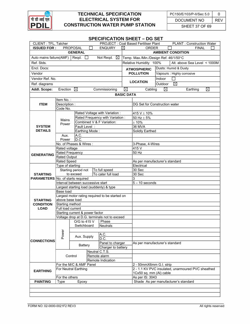
TECHNICAL SPECIFICATION ELECTRICAL SYSTEM FOR
CONSTRUCTION WATER PUMP STATION
PC150/E/103/P-II/Sec 5.0 0 DOCUMENT NO REV
SHEET 37 OF 69
FORM NO: 02-0000-0021F2 REV3 All rights reserved
SPECIFICATION SHEET – DG SET CLIENT : TFL, Talcher PROJECT : Coal Based Fertiliser Plant PLANT : Construction Water ISSUED FOR : PROPOSAL ENQUIRY ORDER FINAL
GENERAL AMBIENT CONDITION Auto mains failure(AMF) Reqd. Not Reqd. Temp. Max./Min./Design Ref. 46/1/50°C Ref. Stds. Relative Humidity 100% Alt. above Sea Level < 1000MEncl. Docs: ATMOSPHERIC
POLLUTION Dusts: Humid & Dusty
Vendor Vapours : Highly corrosive Vendor Ref. No.
LOCATION Indoor
Ref. diagrams Outdoor Addl. Scope: Erection Commissioning Cabling Earthing
BASIC DATA
ITEM Item No. : Description : DG Set for Construction water Code No.
SYSTEM DETAILS
Mains Power
Rated Voltage with Variation : 415 V ± 10% Rated Frequency with Variation : 50 Hz ± 5% Combined V & F Variation: ± 10% Fault Level : 36 MVA Earthing Mode : Solidly Earthed
Aux. Power
A.C. D.C.
No. of Phases & Wires : 3-Phase, 4-Wires
GENERATING
Rated voltage 415 V Rated Frequency 50 Hz Rated Output Rated Speed As per manufacturer’s standard
STARTING PARAMETERS
Type of starting Electrical Starting period not
to exceed To full speed 30 Sec To cater full load 30 Sec
No. of starts required 3 Interval between successive start 5 – 10 seconds Largest starting load (suddenly) & type
STARTING CONDITION
LOAD
Base load Largest motor rating required to be started on above base load
Starting method Full load current Starting current & power factor Voltage drop at D.G. terminals not to exceed
CONNECTIONS
Pow
er
O/G to 415 V Switchboard
Phase Neutrals
Aux. Supply A.C. D.C.
Battery Panel to charger As per manufacturer’s standard Charger to battery
Control Neutral C.T.S. Remote alarm Remote Indication
EARTHING
For the M/C & AMF Panel 2 - 50mmX6mm G.I. strip For Neutral Earthing 2 - 1.1 KV PVC insulated, unarmoured PVC sheathed
1Cx50 sq. mm (Al) cable For the others As per IS: 3043
PAINTING Type Epoxy Shade As per manufacturer’s standard
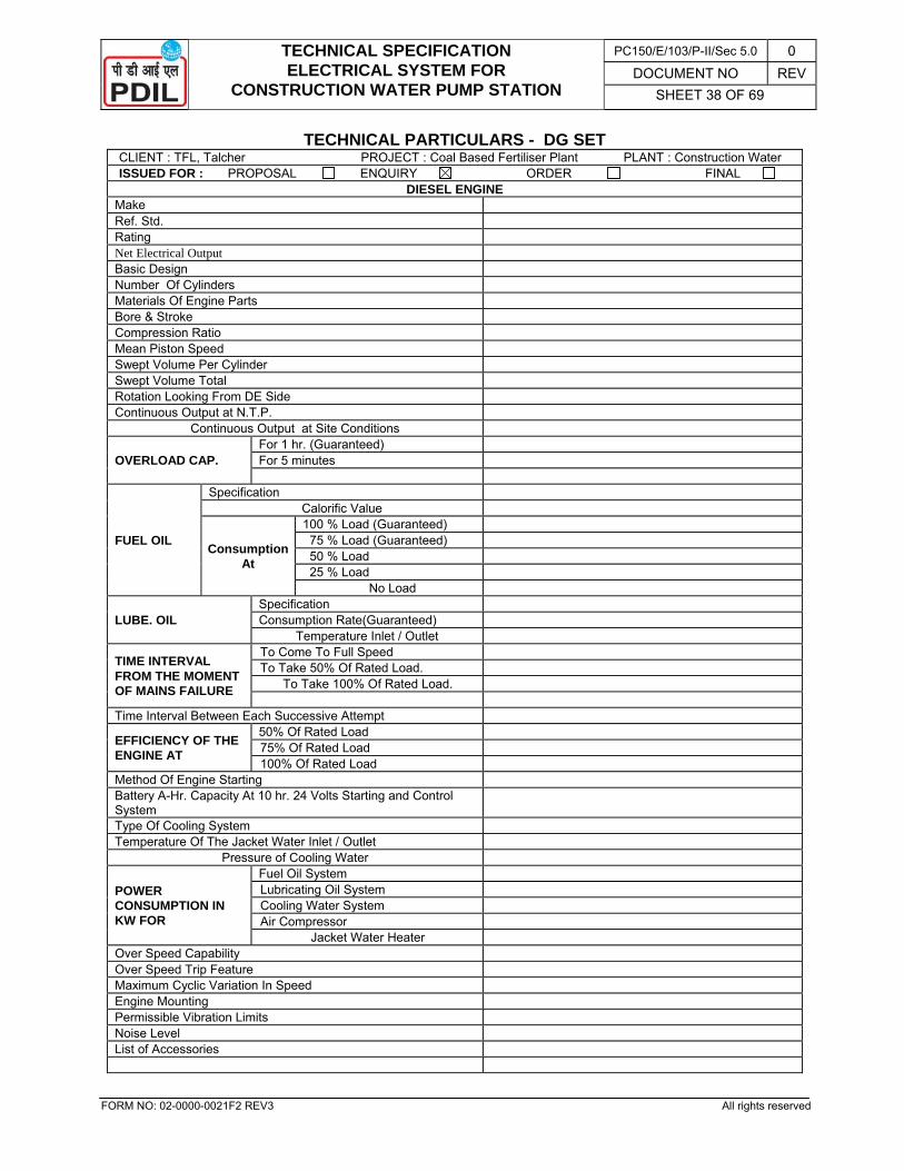
TECHNICAL SPECIFICATION ELECTRICAL SYSTEM FOR
CONSTRUCTION WATER PUMP STATION
PC150/E/103/P-II/Sec 5.0 0 DOCUMENT NO REV
SHEET 38 OF 69
FORM NO: 02-0000-0021F2 REV3 All rights reserved
TECHNICAL PARTICULARS - DG SET CLIENT : TFL, Talcher PROJECT : Coal Based Fertiliser Plant PLANT : Construction Water ISSUED FOR : PROPOSAL ENQUIRY ORDER FINAL
DIESEL ENGINE Make Ref. Std. Rating Net Electrical Output Basic Design Number Of Cylinders Materials Of Engine Parts Bore & Stroke Compression Ratio Mean Piston Speed Swept Volume Per Cylinder Swept Volume Total Rotation Looking From DE Side Continuous Output at N.T.P.
Continuous Output at Site Conditions
OVERLOAD CAP. For 1 hr. (Guaranteed) For 5 minutes
FUEL OIL
Specification Calorific Value
Consumption At
100 % Load (Guaranteed) 75 % Load (Guaranteed) 50 % Load 25 % Load
No Load
LUBE. OIL Specification Consumption Rate(Guaranteed)
Temperature Inlet / Outlet
TIME INTERVAL FROM THE MOMENT OF MAINS FAILURE
To Come To Full Speed To Take 50% Of Rated Load.
To Take 100% Of Rated Load.
Time Interval Between Each Successive Attempt
EFFICIENCY OF THE ENGINE AT
50% Of Rated Load 75% Of Rated Load 100% Of Rated Load
Method Of Engine Starting Battery A-Hr. Capacity At 10 hr. 24 Volts Starting and Control System
Type Of Cooling System Temperature Of The Jacket Water Inlet / Outlet
Pressure of Cooling Water
POWER CONSUMPTION IN KW FOR
Fuel Oil System Lubricating Oil System Cooling Water System Air Compressor
Jacket Water Heater Over Speed Capability Over Speed Trip Feature Maximum Cyclic Variation In Speed Engine Mounting Permissible Vibration Limits Noise Level List of Accessories
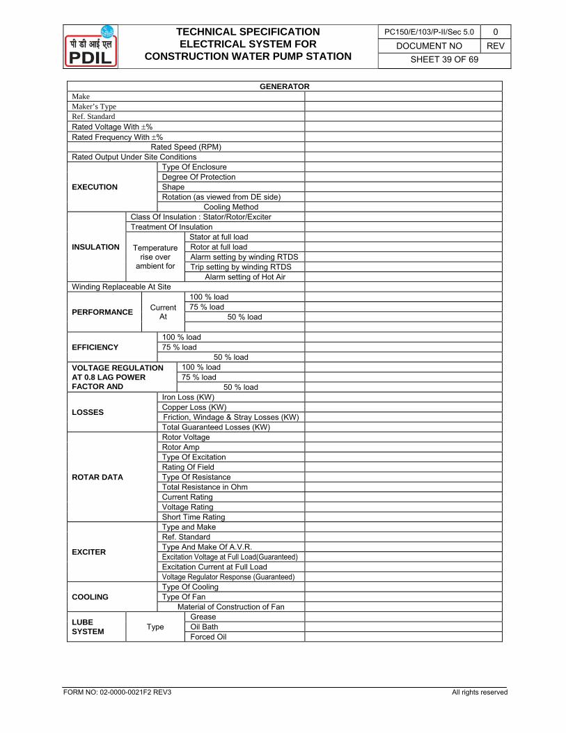
TECHNICAL SPECIFICATION ELECTRICAL SYSTEM FOR
CONSTRUCTION WATER PUMP STATION
PC150/E/103/P-II/Sec 5.0 0 DOCUMENT NO REV
SHEET 39 OF 69
FORM NO: 02-0000-0021F2 REV3 All rights reserved
GENERATOR Make Maker’s Type Ref. Standard Rated Voltage With ±% Rated Frequency With ±%
Rated Speed (RPM) Rated Output Under Site Conditions
EXECUTION
Type Of Enclosure Degree Of Protection Shape Rotation (as viewed from DE side)
Cooling Method
INSULATION
Class Of Insulation : Stator/Rotor/Exciter Treatment Of Insulation
Temperature rise over
ambient for
Stator at full load Rotor at full load Alarm setting by winding RTDS Trip setting by winding RTDS
Alarm setting of Hot Air Winding Replaceable At Site
PERFORMANCE Current At
100 % load 75 % load
50 % load
EFFICIENCY 100 % load 75 % load
50 % load VOLTAGE REGULATION AT 0.8 LAG POWER FACTOR AND
100 % load 75 % load
50 % load
LOSSES
Iron Loss (KW) Copper Loss (KW) Friction, Windage & Stray Losses (KW) Total Guaranteed Losses (KW)
ROTAR DATA
Rotor Voltage Rotor Amp Type Of Excitation Rating Of Field Type Of Resistance Total Resistance in Ohm Current Rating Voltage Rating Short Time Rating
EXCITER
Type and Make Ref. Standard Type And Make Of A.V.R. Excitation Voltage at Full Load(Guaranteed) Excitation Current at Full Load Voltage Regulator Response (Guaranteed)
COOLING Type Of Cooling Type Of Fan
Material of Construction of Fan
LUBE SYSTEM Type
Grease Oil Bath Forced Oil
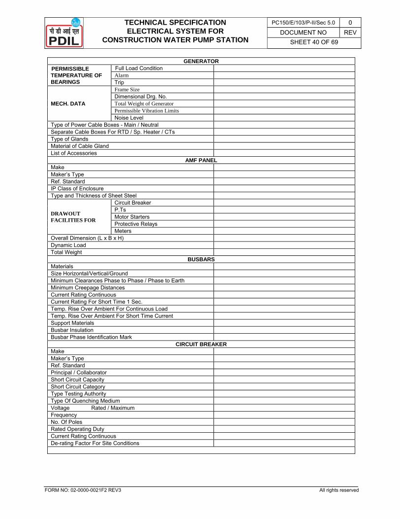
TECHNICAL SPECIFICATION ELECTRICAL SYSTEM FOR
CONSTRUCTION WATER PUMP STATION
PC150/E/103/P-II/Sec 5.0 0 DOCUMENT NO REV
SHEET 40 OF 69
FORM NO: 02-0000-0021F2 REV3 All rights reserved
GENERATOR PERMISSIBLE TEMPERATURE OF BEARINGS
Full Load Condition Alarm Trip
MECH. DATA
Frame Size Dimensional Drg. No. Total Weight of Generator Permissible Vibration Limits Noise Level
Type of Power Cable Boxes - Main / Neutral Separate Cable Boxes For RTD / Sp. Heater / CTs Type of Glands Material of Cable Gland List of Accessories
AMF PANEL Make Maker’s Type Ref. Standard IP Class of Enclosure Type and Thickness of Sheet Steel
DRAWOUT FACILITIES FOR
Circuit Breaker P.Ts Motor Starters Protective Relays Meters
Overall Dimension (L x B x H) Dynamic Load Total Weight
BUSBARS Materials Size Horizontal/Vertical/Ground Minimum Clearances Phase to Phase / Phase to Earth Minimum Creepage Distances Current Rating Continuous Current Rating For Short Time 1 Sec. Temp. Rise Over Ambient For Continuous Load Temp. Rise Over Ambient For Short Time Current Support Materials Busbar Insulation Busbar Phase Identification Mark
CIRCUIT BREAKER Make Maker’s Type Ref. Standard Principal / Collaborator Short Circuit Capacity Short Circuit Category Type Testing Authority Type Of Quenching Medium Voltage Rated / Maximum Frequency No. Of Poles Rated Operating Duty Current Rating Continuous De-rating Factor For Site Conditions
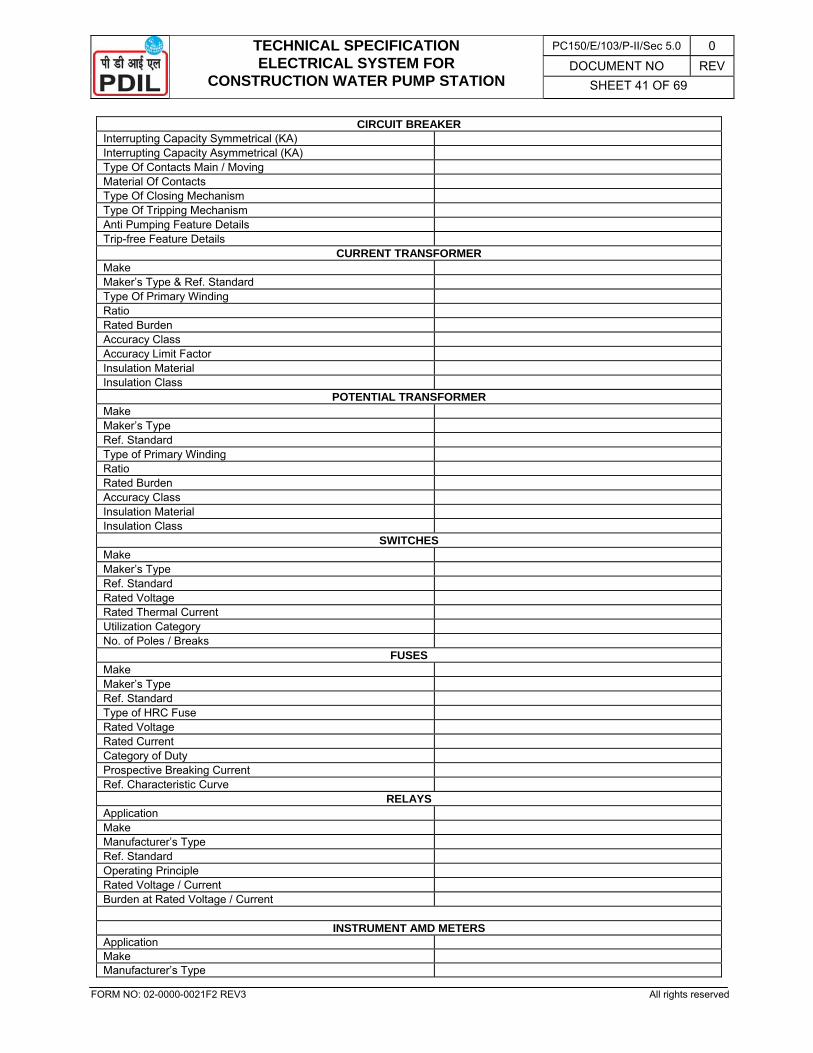
TECHNICAL SPECIFICATION ELECTRICAL SYSTEM FOR
CONSTRUCTION WATER PUMP STATION
PC150/E/103/P-II/Sec 5.0 0 DOCUMENT NO REV
SHEET 41 OF 69
FORM NO: 02-0000-0021F2 REV3 All rights reserved
CIRCUIT BREAKER Interrupting Capacity Symmetrical (KA) Interrupting Capacity Asymmetrical (KA) Type Of Contacts Main / Moving Material Of Contacts Type Of Closing Mechanism Type Of Tripping Mechanism Anti Pumping Feature Details Trip-free Feature Details
CURRENT TRANSFORMER Make Maker’s Type & Ref. Standard Type Of Primary Winding Ratio Rated Burden Accuracy Class Accuracy Limit Factor Insulation Material Insulation Class
POTENTIAL TRANSFORMER Make Maker’s Type Ref. Standard Type of Primary Winding Ratio Rated Burden Accuracy Class Insulation Material Insulation Class
SWITCHES Make Maker’s Type Ref. Standard Rated Voltage Rated Thermal Current Utilization Category No. of Poles / Breaks
FUSES Make Maker’s Type Ref. Standard Type of HRC Fuse Rated Voltage Rated Current Category of Duty Prospective Breaking Current Ref. Characteristic Curve
RELAYS Application Make Manufacturer’s Type Ref. Standard Operating Principle Rated Voltage / Current Burden at Rated Voltage / Current
INSTRUMENT AMD METERS Application Make Manufacturer’s Type
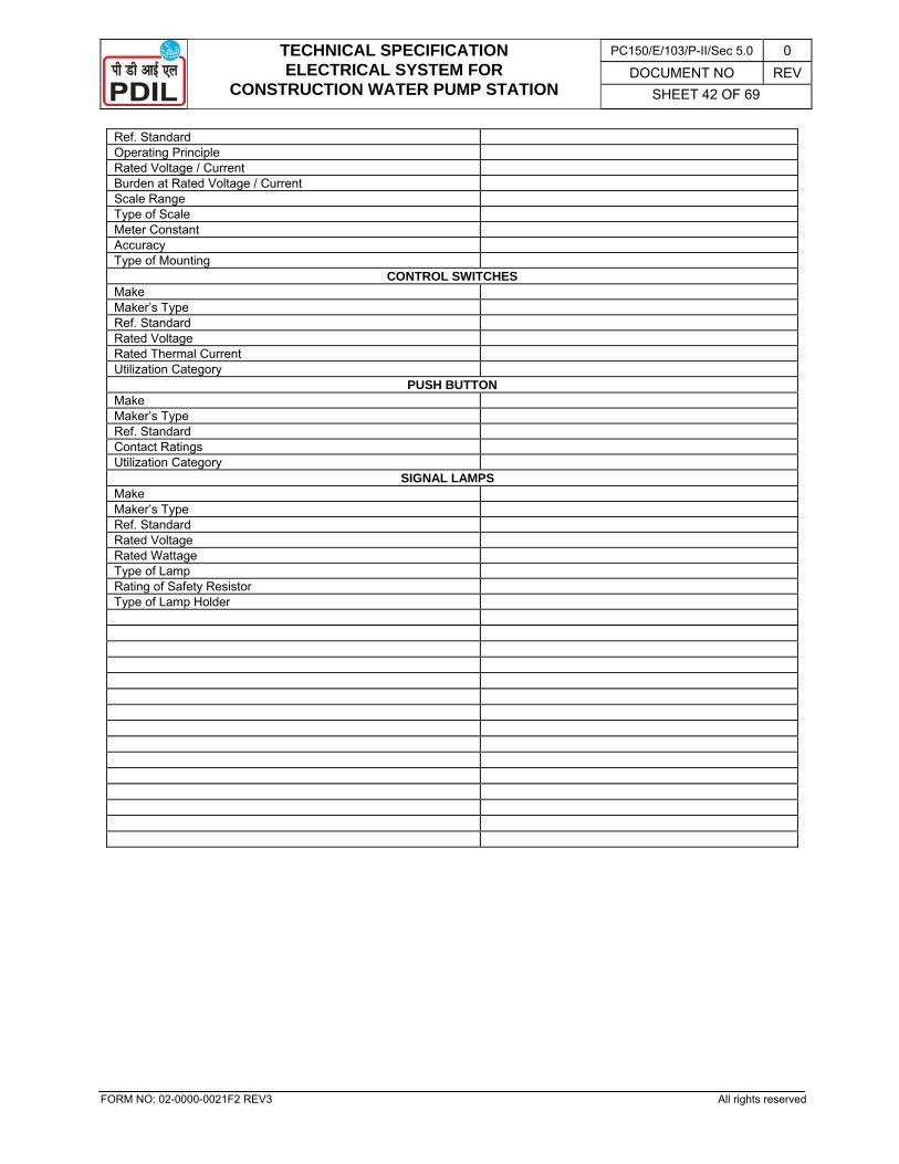
TECHNICAL SPECIFICATION ELECTRICAL SYSTEM FOR
CONSTRUCTION WATER PUMP STATION
PC150/E/103/P-II/Sec 5.0 0 DOCUMENT NO REV
SHEET 42 OF 69
FORM NO: 02-0000-0021F2 REV3 All rights reserved
Ref. Standard Operating Principle Rated Voltage / Current Burden at Rated Voltage / Current Scale Range Type of Scale Meter Constant Accuracy Type of Mounting
CONTROL SWITCHES Make Maker’s Type Ref. Standard Rated Voltage Rated Thermal Current Utilization Category
PUSH BUTTON Make Maker’s Type Ref. Standard Contact Ratings Utilization Category
SIGNAL LAMPS Make Maker’s Type Ref. Standard Rated Voltage Rated Wattage Type of Lamp Rating of Safety Resistor Type of Lamp Holder
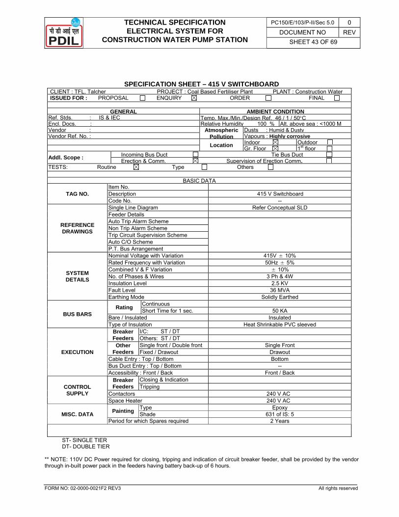
TECHNICAL SPECIFICATION ELECTRICAL SYSTEM FOR
CONSTRUCTION WATER PUMP STATION
PC150/E/103/P-II/Sec 5.0 0 DOCUMENT NO REV
SHEET 43 OF 69
FORM NO: 02-0000-0021F2 REV3 All rights reserved
SPECIFICATION SHEET – 415 V SWITCHBOARD CLIENT : TFL, Talcher PROJECT : Coal Based Fertiliser Plant PLANT : Construction Water ISSUED FOR : PROPOSAL ENQUIRY ORDER FINAL
GENERAL AMBIENT CONDITION Ref. Stds. : IS & IEC Temp. Max./Min./Design Ref. 46 / 1 / 50°C Encl. Docs. : Relative Humidity 100 % Alt. above sea : <1000 MVendor : Atmospheric
PollutionDusts : Humid & Dusty
Vendor Ref. No. : Vapours : Highly corrosive Location Indoor Outdoor Gr. Floor 1st floor Addl. Scope : Incoming Bus Duct Tie Bus Duct
Erection & Comm. Supervision of Erection Comm. TESTS: Routine Type Others
BASIC DATA
TAG NO. Item No. Description 415 V Switchboard Code No. --
REFERENCE DRAWINGS
Single Line Diagram Refer Conceptual SLD Feeder Details Auto Trip Alarm Scheme
Non Trip Alarm Scheme Trip Circuit Supervision Scheme Auto C/O Scheme P.T. Bus Arrangement
SYSTEM DETAILS
Nominal Voltage with Variation 415V ± 10% Rated Frequency with Variation 50Hz ± 5% Combined V & F Variation ± 10% No. of Phases & Wires 3 Ph & 4W Insulation Level 2.5 KV Fault Level 36 MVA Earthing Mode Solidly Earthed
BUS BARS Rating Continuous
Short Time for 1 sec. 50 KA Bare / Insulated Insulated Type of Insulation Heat Shrinkable PVC sleeved
EXECUTION
Breaker Feeders
I/C: ST / DT Others: ST / DT
Other Feeders
Single front / Double front Single Front Fixed / Drawout Drawout
Cable Entry : Top / Bottom Bottom Bus Duct Entry : Top / Bottom -- Accessibility : Front / Back Front / Back
CONTROL SUPPLY
Breaker Feeders
Closing & Indication Tripping
Contactors 240 V AC Space Heater 240 V AC
MISC. DATA Painting Type Epoxy Shade 631 of IS: 5
Period for which Spares required 2 Years
ST- SINGLE TIER DT- DOUBLE TIER
** NOTE: 110V DC Power required for closing, tripping and indication of circuit breaker feeder, shall be provided by the vendor through in-built power pack in the feeders having battery back-up of 6 hours.
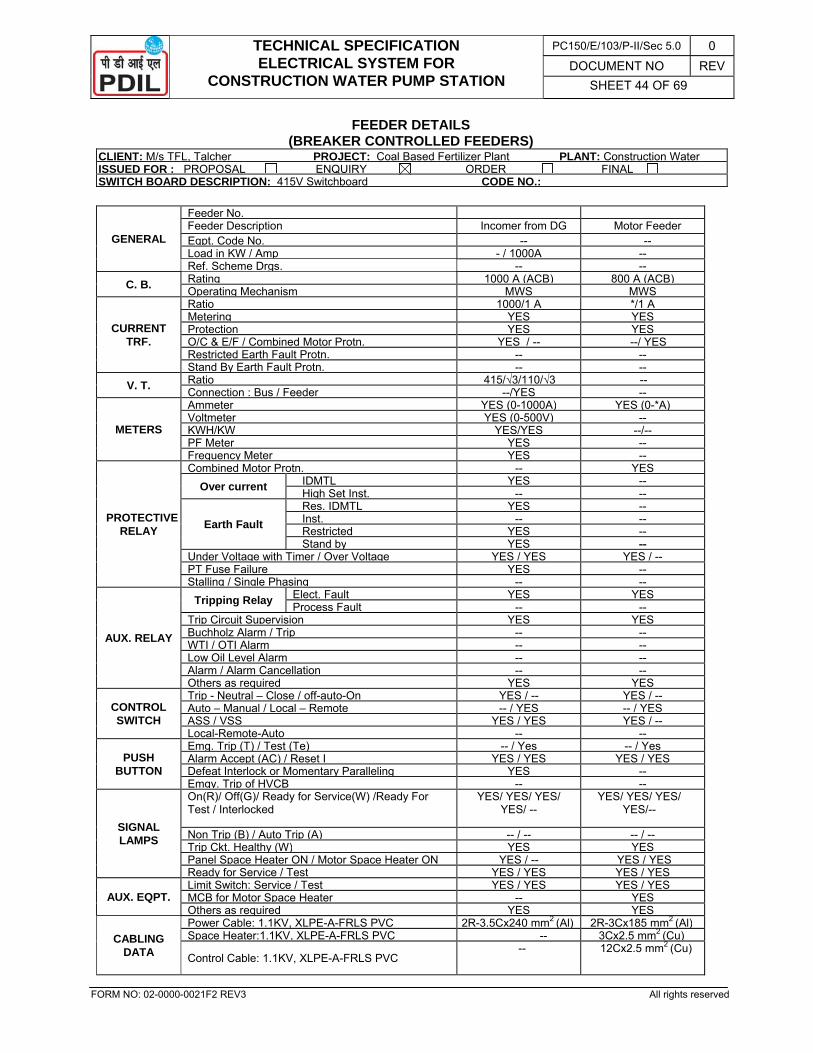
TECHNICAL SPECIFICATION ELECTRICAL SYSTEM FOR
CONSTRUCTION WATER PUMP STATION
PC150/E/103/P-II/Sec 5.0 0 DOCUMENT NO REV
SHEET 44 OF 69
FORM NO: 02-0000-0021F2 REV3 All rights reserved
FEEDER DETAILS (BREAKER CONTROLLED FEEDERS)
CLIENT: M/s TFL, Talcher PROJECT: Coal Based Fertilizer Plant PLANT: Construction WaterISSUED FOR : PROPOSAL ENQUIRY ORDER FINAL SWITCH BOARD DESCRIPTION: 415V Switchboard CODE NO.:
GENERAL
Feeder No. Feeder Description Incomer from DG Motor Feeder Eqpt. Code No. -- -- Load in KW / Amp - / 1000A -- Ref. Scheme Drgs. -- --
C. B. Rating 1000 A (ACB) 800 A (ACB)Operating Mechanism MWS MWS
CURRENT TRF.
Ratio 1000/1 A */1 A Metering YES YESProtection YES YES O/C & E/F / Combined Motor Protn. YES / -- --/ YESRestricted Earth Fault Protn. -- -- Stand By Earth Fault Protn. -- --
V. T. Ratio 415/√3/110/√3 -- Connection : Bus / Feeder --/YES --
METERS
Ammeter YES (0-1000A) YES (0-*A)Voltmeter YES (0-500V) -- KWH/KW YES/YES --/-- PF Meter YES -- Frequency Meter YES --
PROTECTIVE RELAY
Combined Motor Protn. -- YESOver current IDMTL YES --
High Set Inst. -- --
Earth Fault Res. IDMTL YES -- Inst. -- -- Restricted YES -- Stand by YES --
Under Voltage with Timer / Over Voltage YES / YES YES / --PT Fuse Failure YES -- Stalling / Single Phasing -- --
AUX. RELAY
Tripping Relay Elect. Fault YES YESProcess Fault -- --
Trip Circuit Supervision YES YESBuchholz Alarm / Trip -- -- WTI / OTI Alarm -- -- Low Oil Level Alarm -- -- Alarm / Alarm Cancellation -- -- Others as required YES YES
CONTROL SWITCH
Trip - Neutral – Close / off-auto-On YES / -- YES / --Auto – Manual / Local – Remote -- / YES -- / YESASS / VSS YES / YES YES / --Local-Remote-Auto -- --
PUSH BUTTON
Emg. Trip (T) / Test (Te) -- / Yes -- / YesAlarm Accept (AC) / Reset I YES / YES YES / YESDefeat Interlock or Momentary Paralleling YES -- Emgy. Trip of HVCB -- --
SIGNAL LAMPS
On(R)/ Off(G)/ Ready for Service(W) /Ready For Test / Interlocked
YES/ YES/ YES/ YES/ --
YES/ YES/ YES/ YES/--
Non Trip (B) / Auto Trip (A) -- / -- -- / --Trip Ckt. Healthy (W) YES YESPanel Space Heater ON / Motor Space Heater ON YES / -- YES / YESReady for Service / Test YES / YES YES / YES
AUX. EQPT. Limit Switch: Service / Test YES / YES YES / YESMCB for Motor Space Heater -- YESOthers as required YES YES
CABLING DATA
Power Cable: 1.1KV, XLPE-A-FRLS PVC 2R-3.5Cx240 mm2 (Al) 2R-3Cx185 mm2 (Al)Space Heater:1.1KV, XLPE-A-FRLS PVC -- 3Cx2.5 mm2 (Cu)
Control Cable: 1.1KV, XLPE-A-FRLS PVC -- 12Cx2.5 mm2 (Cu)
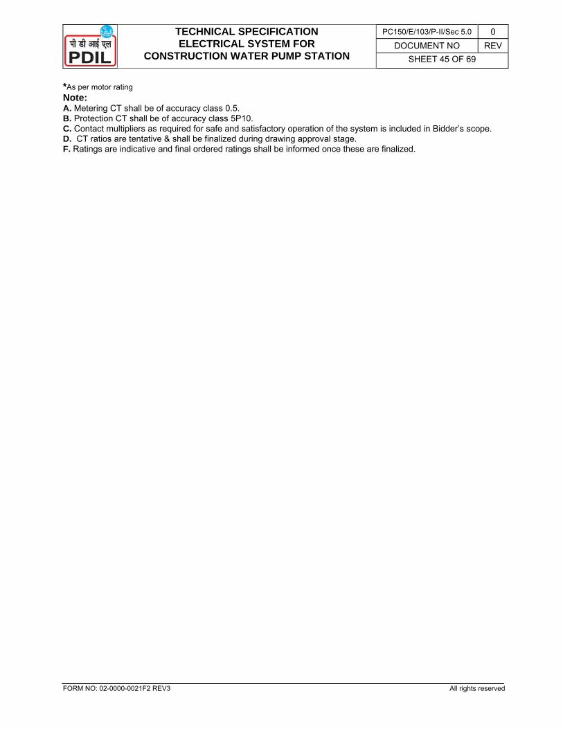
TECHNICAL SPECIFICATION ELECTRICAL SYSTEM FOR
CONSTRUCTION WATER PUMP STATION
PC150/E/103/P-II/Sec 5.0 0 DOCUMENT NO REV
SHEET 45 OF 69
FORM NO: 02-0000-0021F2 REV3 All rights reserved
*As per motor rating Note: A. Metering CT shall be of accuracy class 0.5. B. Protection CT shall be of accuracy class 5P10. C. Contact multipliers as required for safe and satisfactory operation of the system is included in Bidder’s scope. D. CT ratios are tentative & shall be finalized during drawing approval stage. F. Ratings are indicative and final ordered ratings shall be informed once these are finalized.
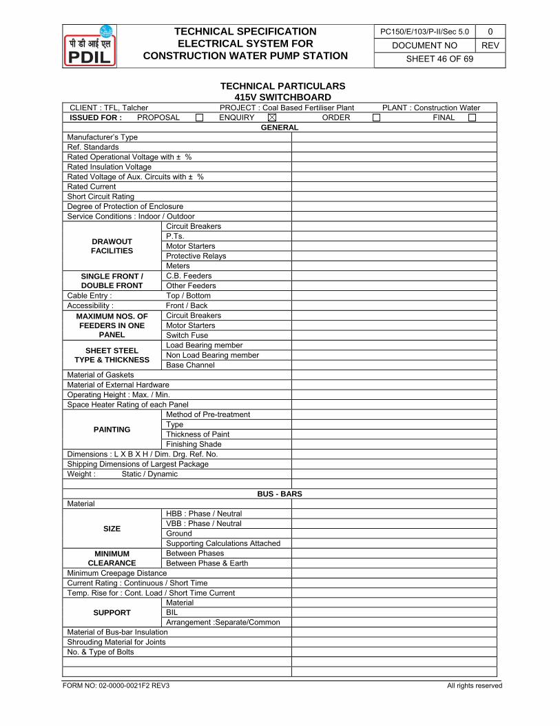
TECHNICAL SPECIFICATION ELECTRICAL SYSTEM FOR
CONSTRUCTION WATER PUMP STATION
PC150/E/103/P-II/Sec 5.0 0 DOCUMENT NO REV
SHEET 46 OF 69
FORM NO: 02-0000-0021F2 REV3 All rights reserved
TECHNICAL PARTICULARS 415V SWITCHBOARD
CLIENT : TFL, Talcher PROJECT : Coal Based Fertiliser Plant PLANT : Construction Water ISSUED FOR : PROPOSAL ENQUIRY ORDER FINAL
GENERAL Manufacturer’s Type Ref. Standards Rated Operational Voltage with ± % Rated Insulation Voltage Rated Voltage of Aux. Circuits with ± % Rated Current Short Circuit Rating Degree of Protection of Enclosure Service Conditions : Indoor / Outdoor
DRAWOUT FACILITIES
Circuit Breakers P.Ts. Motor Starters Protective Relays Meters
SINGLE FRONT / DOUBLE FRONT
C.B. Feeders Other Feeders
Cable Entry : Top / Bottom Accessibility : Front / Back
MAXIMUM NOS. OF FEEDERS IN ONE
PANEL
Circuit Breakers Motor Starters Switch Fuse
SHEET STEEL TYPE & THICKNESS
Load Bearing member Non Load Bearing member Base Channel
Material of Gaskets Material of External Hardware Operating Height : Max. / Min. Space Heater Rating of each Panel
PAINTING
Method of Pre-treatment Type Thickness of Paint Finishing Shade
Dimensions : L X B X H / Dim. Drg. Ref. No. Shipping Dimensions of Largest Package Weight : Static / Dynamic
BUS - BARS Material
SIZE
HBB : Phase / Neutral VBB : Phase / Neutral Ground Supporting Calculations Attached
MINIMUM CLEARANCE
Between Phases Between Phase & Earth
Minimum Creepage Distance Current Rating : Continuous / Short Time Temp. Rise for : Cont. Load / Short Time Current
SUPPORT Material BIL Arrangement :Separate/Common
Material of Bus-bar Insulation Shrouding Material for Joints No. & Type of Bolts
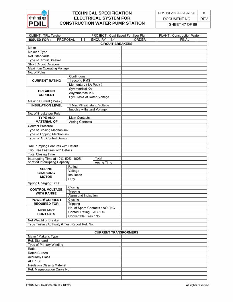
TECHNICAL SPECIFICATION ELECTRICAL SYSTEM FOR
CONSTRUCTION WATER PUMP STATION
PC150/E/103/P-II/Sec 5.0 0 DOCUMENT NO REV
SHEET 47 OF 69
FORM NO: 02-0000-0021F2 REV3 All rights reserved
CLIENT : TFL, Talcher PROJECT : Coal Based Fertiliser Plant PLANT : Construction Water ISSUED FOR : PROPOSAL ENQUIRY ORDER FINAL
CIRCUIT BREAKERS Make Maker’s Type Ref. Standards Type of Circuit Breaker Short Circuit Category Maximum Operating Voltage No. of Poles
CURRENT RATING Continuous 1 second RMS Momentary ( kA Peak )
BREAKING CURRENT
Symmetrical KA Asymmetrical KA Sym. MVA at Rated Voltage
Making Current ( Peak ) INSULATION LEVEL 1 Min. PF withstand Voltage
Impulse withstand Voltage No. of Breaks per Pole
TYPE AND MATERIAL OF
Main Contacts Arcing Contacts
Contact Pressure Type of Closing Mechanism Type of Tripping Mechanism Type of Arc Control Device
Arc Pumping Features with Details Trip Free Features with Details Total Closing Time Interrupting Time at 10%, 50%, 100% of rated Interrupting Capacity
Total Arcing Time
SPRING CHARGING
MOTOR
Rating Voltage Insulation Duty
Spring Charging Time
CONTROL VOLTAGE WITH RANGE
Closing Tripping Alarm and Indication
POWER/ CURRENT REQUIRED FOR
Closing Tripping
AUXILIARY CONTACTS
No. of Spare Contacts : NO / NC Contact Rating : AC / DC Convertible : Yes / No
Net Weight of Breaker Type Testing Authority & Test Report Ref. No.
CURRENT TRANSFORMERS Make / Maker’s Type Ref. Standard Type of Primary Winding Ratio Rated Burden Accuracy Class ALF / ISF Insulation Class & Material Ref. Magnetisation Curve No.
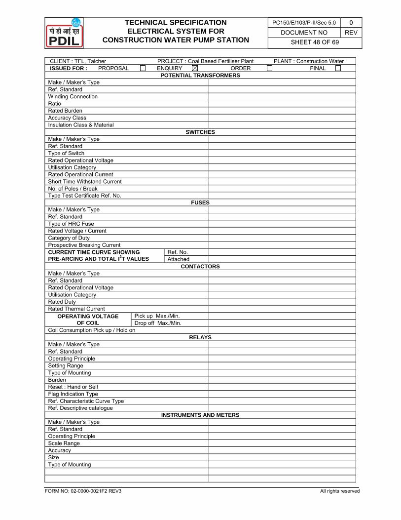
TECHNICAL SPECIFICATION ELECTRICAL SYSTEM FOR
CONSTRUCTION WATER PUMP STATION
PC150/E/103/P-II/Sec 5.0 0 DOCUMENT NO REV
SHEET 48 OF 69
FORM NO: 02-0000-0021F2 REV3 All rights reserved
CLIENT : TFL, Talcher PROJECT : Coal Based Fertiliser Plant PLANT : Construction Water ISSUED FOR : PROPOSAL ENQUIRY ORDER FINAL
POTENTIAL TRANSFORMERS Make / Maker’s Type Ref. Standard Winding Connection Ratio Rated Burden Accuracy Class Insulation Class & Material
SWITCHES Make / Maker’s Type Ref. Standard Type of Switch Rated Operational Voltage Utilisation Category Rated Operational Current Short Time Withstand Current No. of Poles / Break Type Test Certificate Ref. No.
FUSES Make / Maker’s Type Ref. Standard Type of HRC Fuse Rated Voltage / Current Category of Duty Prospective Breaking Current CURRENT TIME CURVE SHOWING PRE-ARCING AND TOTAL I2T VALUES
Ref. No. Attached
CONTACTORS Make / Maker’s Type Ref. Standard Rated Operational Voltage Utilisation Category Rated Duty Rated Thermal Current
OPERATING VOLTAGE OF COIL
Pick up Max./Min. Drop off Max./Min.
Coil Consumption Pick up / Hold on RELAYS
Make / Maker’s Type Ref. Standard Operating Principle Setting Range Type of Mounting Burden Reset : Hand or Self Flag Indication Type Ref. Characteristic Curve Type Ref. Descriptive catalogue
INSTRUMENTS AND METERS Make / Maker’s Type Ref. Standard Operating Principle Scale Range Accuracy Size Type of Mounting
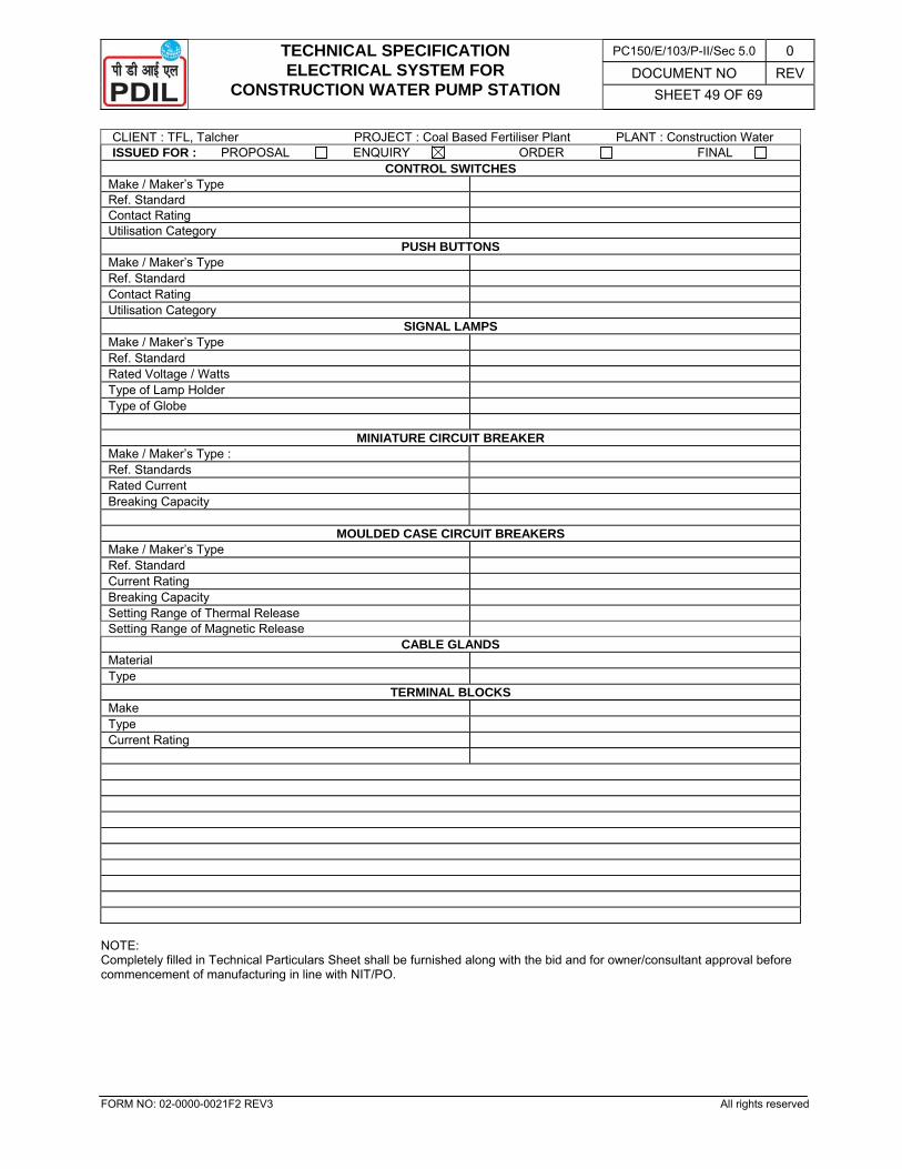
TECHNICAL SPECIFICATION ELECTRICAL SYSTEM FOR
CONSTRUCTION WATER PUMP STATION
PC150/E/103/P-II/Sec 5.0 0 DOCUMENT NO REV
SHEET 49 OF 69
FORM NO: 02-0000-0021F2 REV3 All rights reserved
CLIENT : TFL, Talcher PROJECT : Coal Based Fertiliser Plant PLANT : Construction Water ISSUED FOR : PROPOSAL ENQUIRY ORDER FINAL
CONTROL SWITCHES Make / Maker’s Type Ref. Standard Contact Rating Utilisation Category
PUSH BUTTONS Make / Maker’s Type Ref. Standard Contact Rating Utilisation Category
SIGNAL LAMPS Make / Maker’s Type Ref. Standard Rated Voltage / Watts Type of Lamp Holder Type of Globe
MINIATURE CIRCUIT BREAKER Make / Maker’s Type : Ref. Standards Rated Current Breaking Capacity
MOULDED CASE CIRCUIT BREAKERS
Make / Maker’s Type Ref. Standard Current Rating Breaking Capacity Setting Range of Thermal Release Setting Range of Magnetic Release
CABLE GLANDS Material Type
TERMINAL BLOCKS Make Type Current Rating
NOTE: Completely filled in Technical Particulars Sheet shall be furnished along with the bid and for owner/consultant approval before commencement of manufacturing in line with NIT/PO.
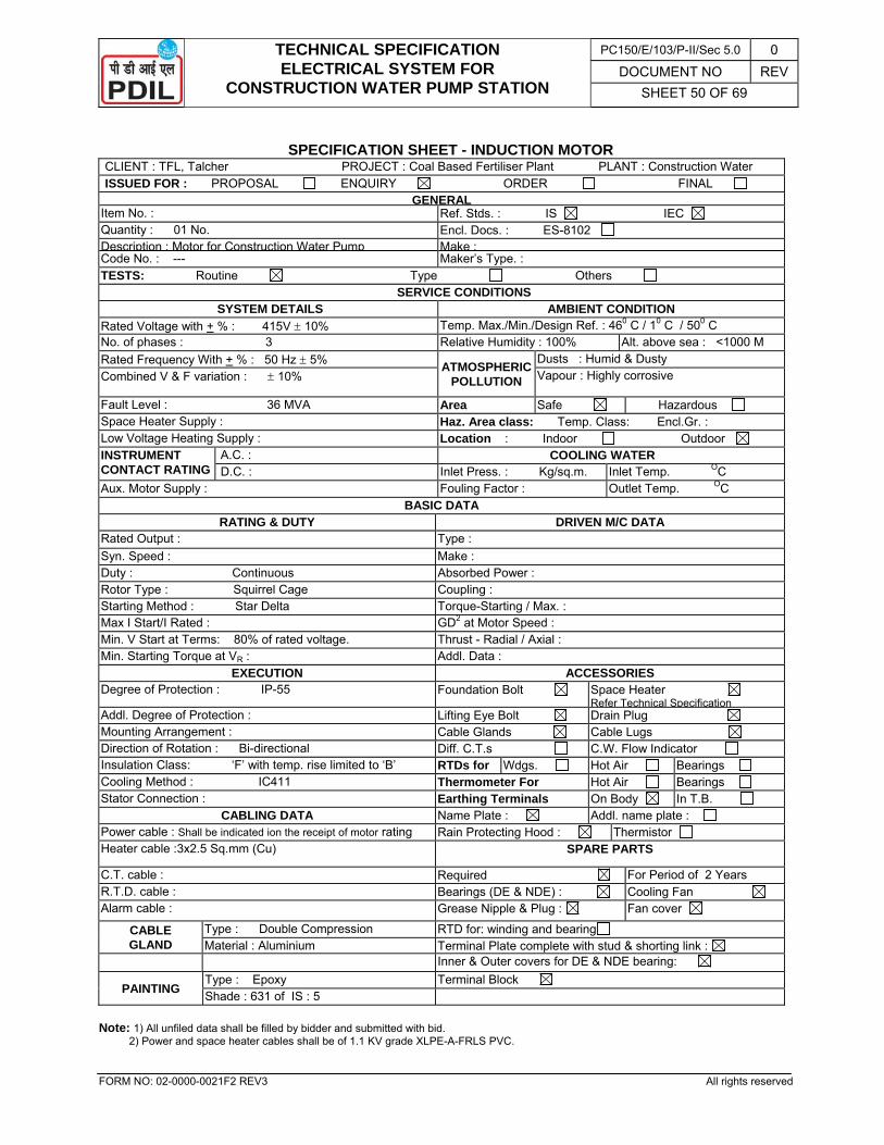
TECHNICAL SPECIFICATION ELECTRICAL SYSTEM FOR
CONSTRUCTION WATER PUMP STATION
PC150/E/103/P-II/Sec 5.0 0 DOCUMENT NO REV
SHEET 50 OF 69
FORM NO: 02-0000-0021F2 REV3 All rights reserved
SPECIFICATION SHEET - INDUCTION MOTOR
CLIENT : TFL, Talcher PROJECT : Coal Based Fertiliser Plant PLANT : Construction Water ISSUED FOR : PROPOSAL ENQUIRY ORDER FINAL
GENERALItem No. : Ref. Stds. : IS IEC Quantity : 01 No. Encl. Docs. : ES-8102 Description : Motor for Construction Water Pump Make :Code No. : --- Maker’s Type. : TESTS: Routine Type Others
SERVICE CONDITIONS SYSTEM DETAILS AMBIENT CONDITION
Rated Voltage with + % : 415V ± 10% Temp. Max./Min./Design Ref. : 460 C / 10 C / 500 C No. of phases : 3 Relative Humidity : 100% Alt. above sea : <1000 M Rated Frequency With + % : 50 Hz ± 5% ATMOSPHERIC
POLLUTION
Dusts : Humid & Dusty Combined V & F variation : ± 10% Vapour : Highly corrosive
Fault Level : 36 MVA Area Safe Hazardous Space Heater Supply : Haz. Area class: Temp. Class: Encl.Gr. : Low Voltage Heating Supply : Location : Indoor Outdoor INSTRUMENT CONTACT RATING
A.C. : COOLING WATER D.C. : Inlet Press. : Kg/sq.m. Inlet Temp. OC
Aux. Motor Supply : Fouling Factor : Outlet Temp. OC BASIC DATA
RATING & DUTY DRIVEN M/C DATA Rated Output : Type : Syn. Speed : Make : Duty : Continuous Absorbed Power : Rotor Type : Squirrel Cage Coupling : Starting Method : Star Delta Torque-Starting / Max. : Max I Start/I Rated : GD2 at Motor Speed :Min. V Start at Terms: 80% of rated voltage. Thrust - Radial / Axial : Min. Starting Torque at VR : Addl. Data :
EXECUTION ACCESSORIES Degree of Protection : IP-55 Foundation Bolt Space Heater
Refer Technical SpecificationAddl. Degree of Protection : Lifting Eye Bolt Drain Plug Mounting Arrangement : Cable Glands Cable Lugs Direction of Rotation : Bi-directional Diff. C.T.s C.W. Flow Indicator Insulation Class: ‘F’ with temp. rise limited to ‘B’ RTDs for Wdgs. Hot Air Bearings Cooling Method : IC411 Thermometer For Hot Air Bearings Stator Connection : Earthing Terminals On Body In T.B.
CABLING DATA Name Plate : Addl. name plate : Power cable : Shall be indicated ion the receipt of motor rating Rain Protecting Hood : Thermistor Heater cable :3x2.5 Sq.mm (Cu) SPARE PARTS
C.T. cable : Required For Period of 2 Years R.T.D. cable : Bearings (DE & NDE) : Cooling Fan Alarm cable : Grease Nipple & Plug : Fan cover
CABLE GLAND
Type : Double Compression RTD for: winding and bearing Material : Aluminium Terminal Plate complete with stud & shorting link :
Inner & Outer covers for DE & NDE bearing:
PAINTING Type : Epoxy Terminal Block Shade : 631 of IS : 5
Note: 1) All unfiled data shall be filled by bidder and submitted with bid. 2) Power and space heater cables shall be of 1.1 KV grade XLPE-A-FRLS PVC.
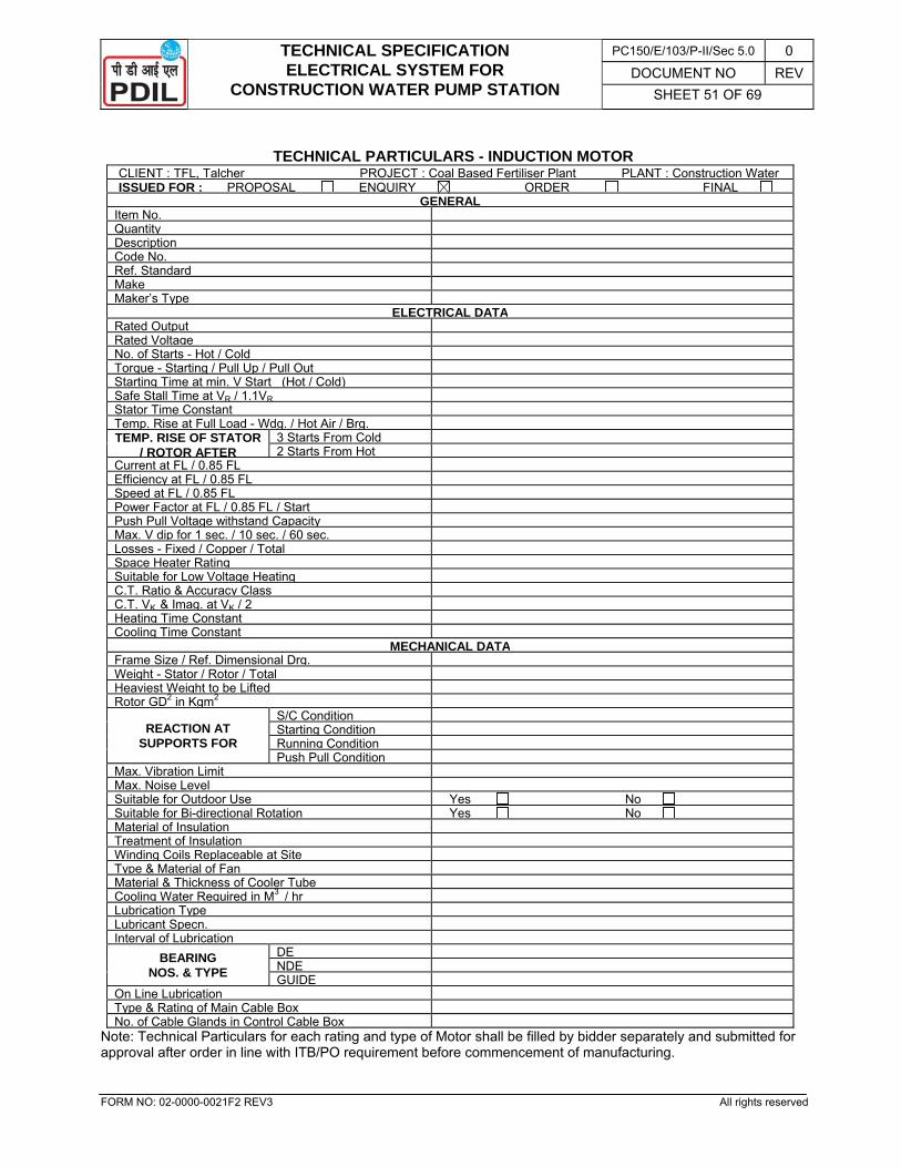
TECHNICAL SPECIFICATION ELECTRICAL SYSTEM FOR
CONSTRUCTION WATER PUMP STATION
PC150/E/103/P-II/Sec 5.0 0 DOCUMENT NO REV
SHEET 51 OF 69
FORM NO: 02-0000-0021F2 REV3 All rights reserved
TECHNICAL PARTICULARS - INDUCTION MOTOR
CLIENT : TFL, Talcher PROJECT : Coal Based Fertiliser Plant PLANT : Construction Water ISSUED FOR : PROPOSAL ENQUIRY ORDER FINAL
GENERALItem No. Quantity Description Code No. Ref. Standard Make Maker’s Type
ELECTRICAL DATARated Output Rated Voltage No. of Starts - Hot / Cold Torque - Starting / Pull Up / Pull Out Starting Time at min. V Start (Hot / Cold) Safe Stall Time at VR / 1.1VR Stator Time Constant Temp. Rise at Full Load - Wdg. / Hot Air / Brg.TEMP. RISE OF STATOR
/ ROTOR AFTER 3 Starts From Cold2 Starts From Hot
Current at FL / 0.85 FL Efficiency at FL / 0.85 FL Speed at FL / 0.85 FL Power Factor at FL / 0.85 FL / Start Push Pull Voltage withstand Capacity Max. V dip for 1 sec. / 10 sec. / 60 sec. Losses - Fixed / Copper / Total Space Heater Rating Suitable for Low Voltage Heating C.T. Ratio & Accuracy Class C.T. VK & Imag. at VK / 2 Heating Time Constant Cooling Time Constant
MECHANICAL DATAFrame Size / Ref. Dimensional Drg. Weight - Stator / Rotor / Total Heaviest Weight to be LiftedRotor GD2 in Kgm2
REACTION AT SUPPORTS FOR
S/C Condition Starting ConditionRunning ConditionPush Pull Condition
Max. Vibration Limit Max. Noise Level Suitable for Outdoor Use Yes No Suitable for Bi-directional Rotation Yes No Material of Insulation Treatment of Insulation Winding Coils Replaceable at Site Type & Material of Fan Material & Thickness of Cooler Tube Cooling Water Required in M3 / hr Lubrication Type Lubricant Specn. Interval of Lubrication
BEARING NOS. & TYPE
DE NDE GUIDE
On Line Lubrication Type & Rating of Main Cable Box No. of Cable Glands in Control Cable Box
Note: Technical Particulars for each rating and type of Motor shall be filled by bidder separately and submitted for approval after order in line with ITB/PO requirement before commencement of manufacturing.
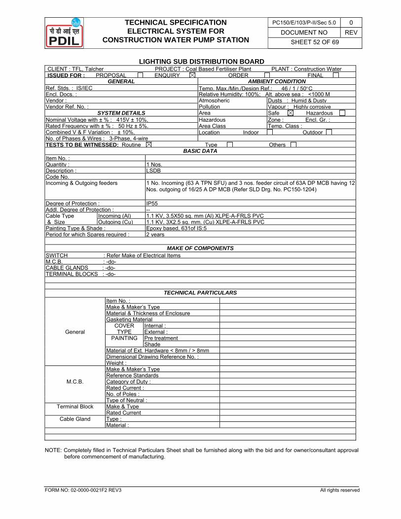
TECHNICAL SPECIFICATION ELECTRICAL SYSTEM FOR
CONSTRUCTION WATER PUMP STATION
PC150/E/103/P-II/Sec 5.0 0 DOCUMENT NO REV
SHEET 52 OF 69
FORM NO: 02-0000-0021F2 REV3 All rights reserved
LIGHTING SUB DISTRIBUTION BOARD CLIENT : TFL, Talcher PROJECT : Coal Based Fertiliser Plant PLANT : Construction Water ISSUED FOR : PROPOSAL ENQUIRY ORDER FINAL
GENERAL AMBIENT CONDITION Ref. Stds. : IS/IEC Temp. Max./Min./Design Ref.: 46 / 1 / 50°C Encl. Docs. : Relative Humidity: 100%; Alt. above sea : <1000 MVendor : Atmospheric Dusts : Humid & DustyVendor Ref. No. : Pollution Vapour : Highly corrosive
SYSTEM DETAILS Area Safe Hazardous Nominal Voltage with ± % : 415V ± 10%, Hazardous Zone : Encl. Gr. : Rated Frequency with ± % : 50 Hz ± 5%, Area Class Temp. Class : Combined V & F Variation : ± 10%, Location Indoor Outdoor No. of Phases & Wires : 3-Phase, 4-wire TESTS TO BE WITNESSED: Routine Type Others
BASIC DATA Item No. : Quantity : 1 Nos.Description : LSDB Code No. Incoming & Outgoing feeders 1 No. Incoming (63 A TPN SFU) and 3 nos. feeder circuit of 63A DP MCB having 12
Nos. outgoing of 16/25 A DP MCB (Refer SLD Drg. No. PC150-1204)
Degree of Protection : IP55 Addl. Degree of Protection : -- Cable Type Incoming (Al) 1.1 KV, 3.5X50 sq. mm (Al) XLPE-A-FRLS PVC & Size Outgoing (Cu) 1.1 KV, 3X2.5 sq. mm. (Cu) XLPE-A-FRLS PVC Painting Type & Shade : Epoxy based, 631of IS:5Period for which Spares required : 2 years
MAKE OF COMPONENTS
SWITCH : Refer Make of Electrical ItemsM.C.B. : -do- CABLE GLANDS : -do- TERMINAL BLOCKS : -do-
TECHNICAL PARTICULARS Item No. : Make & Maker’s Type Material & Thickness of Enclosure Gasketing Material
COVER Internal :General TYPE External :
PAINTING Pre treatment Shade Material of Ext. Hardware < 8mm / > 8mm Dimensional Drawing Reference No. : Weight : Make & Maker’s Type Reference Standards
M.C.B. Category of Duty : Rated Current : No. of Poles : Type of Neutral :
Terminal Block Make & Type Rated Current
Cable Gland Type : Material :
NOTE: Completely filled in Technical Particulars Sheet shall be furnished along with the bid and for owner/consultant approval
before commencement of manufacturing.
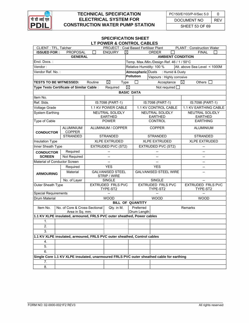
TECHNICAL SPECIFICATION ELECTRICAL SYSTEM FOR
CONSTRUCTION WATER PUMP STATION
PC150/E/103/P-II/Sec 5.0 0 DOCUMENT NO REV
SHEET 53 OF 69
FORM NO: 02-0000-0021F2 REV3 All rights reserved
SPECIFICATION SHEET LT POWER & CONTROL CABLES
CLIENT : TFL, Talcher PROJECT : Coal Based Fertiliser Plant PLANT : Construction Water ISSUED FOR : PROPOSAL ENQUIRY ORDER FINAL
GENERAL AMBIENT CONDITION Encl. Docs. : Temp. Max./Min./Design Ref. 46 / 1 / 50°C Vendor : Relative Humidity: 100 % Alt. above Sea Level < 1000M Vendor Ref. No. : Atmospheric
Pollution Dusts : Humid & Dusty
Vapours : Highly corrosive TESTS TO BE WITNESSED: Routine Type Acceptance Others Type Tests Certificate of Similar Cable : Required Not required
BASIC DATA Item No. Ref. Stds. IS:7098 (PART-1) IS:7098 (PART-1) IS:7098 (PART-1) Voltage Grade 1.1 KV POWER CABLE 1.1 KV CONTROL CABLE 1.1 KV EARTHING CABLESystem Earthing NEUTRAL SOLIDLY
EARTHED NEUTRAL SOLIDLY
EARTHED NEUTRAL SOLIDLY
EARTHED Type of Cable POWER CONTROL EARTHING
CONDUCTOR ALUMINIUM/
COPPER ALUMINIUM / COPPER COPPER ALUMINIUM
STRANDED STRANDED STRANDED STRANDED Insulation Type XLPE EXTRUDED XLPE EXTRUDED XLPE EXTRUDED Inner Sheath Type EXTRUDED PVC (ST2) EXTRUDED PVC (ST2) --
CONDUCTOR SCREEN
Required -- -- -- Not Required -- -- --
Material of Conductor Screen -- -- --
ARMOURING
Required YES YES -- Material GALVANISED STEEL
STRIP / WIRE GALVANISED STEEL WIRE --
No. of Layer SINGLE SINGLE -- Outer Sheath Type EXTRUDED FRLS PVC
TYPE-ST2 EXTRUDED FRLS PVC
TYPE-ST2 EXTRUDED FRLS PVC
TYPE-ST2 Special Requirements -- -- -- Drum Material WOOD WOOD WOOD
BILL OF QUANTITY Item No. No. of Core & Cross-Sectional
Area in Sq. mm. Qty. in M. Preferred
Drum LengthRemarks
1.1 KV XLPE insulated, armoured, FRLS PVC outer sheathed, Power cables 1. 2. 3.
1.1 KV XLPE insulated, armoured, FRLS PVC outer sheathed, Control cables 4. 5. 6.
Single Core 1.1 KV XLPE insulated, unarmoured FRLS PVC outer sheathed cable for earthing 7. 8.
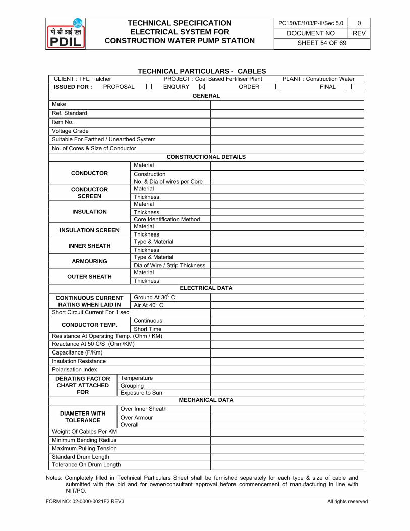
TECHNICAL SPECIFICATION ELECTRICAL SYSTEM FOR
CONSTRUCTION WATER PUMP STATION
PC150/E/103/P-II/Sec 5.0 0 DOCUMENT NO REV
SHEET 54 OF 69
FORM NO: 02-0000-0021F2 REV3 All rights reserved
TECHNICAL PARTICULARS - CABLES
CLIENT : TFL, Talcher PROJECT : Coal Based Fertiliser Plant PLANT : Construction Water ISSUED FOR : PROPOSAL ENQUIRY ORDER FINAL
GENERAL Make Ref. Standard Item No. Voltage Grade Suitable For Earthed / Unearthed System No. of Cores & Size of Conductor
CONSTRUCTIONAL DETAILS
CONDUCTOR Material Construction No. & Dia of wires per Core
CONDUCTOR SCREEN
Material Thickness
INSULATION Material Thickness Core Identification Method
INSULATION SCREEN Material Thickness
INNER SHEATH Type & Material Thickness
ARMOURING Type & Material Dia of Wire / Strip Thickness
OUTER SHEATH Material Thickness
ELECTRICAL DATA CONTINUOUS CURRENT RATING WHEN LAID IN
Ground At 300 C Air At 400 C
Short Circuit Current For 1 sec.
CONDUCTOR TEMP. Continuous Short Time
Resistance At Operating Temp. (Ohm / KM) Reactance At 50 C/S (Ohm/KM) Capacitance (F/Km) Insulation Resistance Polarisation Index
DERATING FACTOR CHART ATTACHED
FOR
Temperature Grouping Exposure to Sun
MECHANICAL DATA
DIAMETER WITH TOLERANCE
Over Inner Sheath Over Armour Overall
Weight Of Cables Per KM Minimum Bending Radius Maximum Pulling Tension Standard Drum Length Tolerance On Drum Length
Notes: Completely filled in Technical Particulars Sheet shall be furnished separately for each type & size of cable and submitted with the bid and for owner/consultant approval before commencement of manufacturing in line with NIT/PO.
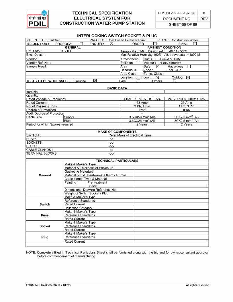
TECHNICAL SPECIFICATION ELECTRICAL SYSTEM FOR
CONSTRUCTION WATER PUMP STATION
PC150/E/103/P-II/Sec 5.0 0 DOCUMENT NO REV
SHEET 55 OF 69
FORM NO: 02-0000-0021F2 REV3 All rights reserved
INTERLOCKING SWITCH SOCKET & PLUG CLIENT : TFL, Talcher PROJECT : Coal Based Fertiliser Plant PLANT : Construction Water ISSUED FOR : PROPOSAL ENQUIRY ORDER FINAL
GENERAL AMBIENT CONDITION Ref. Stds. : IS / IEC Temp.- Max / Min / Design ref.: 46 / 1 / 50°C Encl. Docs. : Max Relative Humidity 100% Alt. above sea : <1000 M Vendor : Atmospheric Dusts : Humid & Dusty Vendor Ref. No. : Pollution Vapour : Highly corrosive Sample Reqd. : Area Safe Hazardous Hazardous Zone : Encl. Gr. : Area Class Temp. Class : Location : Indoor Outdoor TESTS TO BE WITNESSED : Routine Type Others
BASIC DATAItem No. Quantity Rated Voltage & Frequency 415V ± 10 %, 50Hz ± 5% 240V ± 10 %, 50Hz ± 5%Rated Current 63 Amp 25 AmpNo. of Phases & Pins 3 Ph, 4 Pin 1 Ph, 3 PinDegree of Protection IP55 IP55Addl. Degree of Protection -- --Cable Size Supply 3.5CX50 mm2 (Al) 3CX2.5 mm2 (Al) Plug 3.5CX25 mm2 (Al) 3CX2.5 mm2 (Al)Period for which Spares required 2 Years 2 Years
MAKE OF COMPONENTS SWITCH : Refer Make of Electrical ItemsFUSE: -do-SOCKETS : -do-PLUG : -do-CABLE GLANDS : -do-TERMINAL BLOCKS : -do-
TECHNICAL PARTICULARS Make & Maker’s Type Material & Thickness of Enclosure Gasketing Materials
General Material of Ext. Hardwares < 8mm / > 8mm Cable glands Type & Material Painting Pre treatment Shade Dimensional Drawing Reference No. Weight of Switch Socket / Plug Make & Maker’s Type Reference Standards
Switch Rated Current Utilisation Category Make & Maker’s Type
Fuse Reference Standards Rated Current Make & Maker’s Type
Socket Reference Standards Rated Current Make & Maker’s Type
Plug Reference Standards Rated Current NOTE: Completely filled in Technical Particulars Sheet shall be furnished along with the bid and for owner/consultant approval
before commencement of manufacturing.
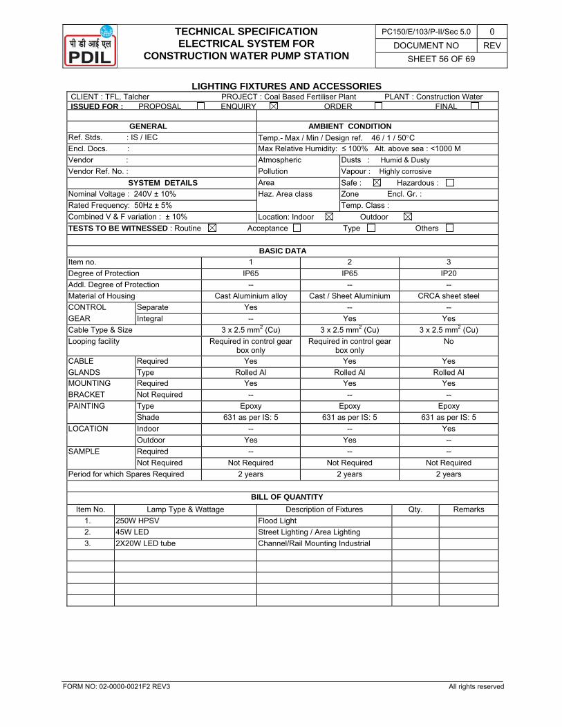
TECHNICAL SPECIFICATION ELECTRICAL SYSTEM FOR
CONSTRUCTION WATER PUMP STATION
PC150/E/103/P-II/Sec 5.0 0 DOCUMENT NO REV
SHEET 56 OF 69
FORM NO: 02-0000-0021F2 REV3 All rights reserved
LIGHTING FIXTURES AND ACCESSORIES CLIENT : TFL, Talcher PROJECT : Coal Based Fertiliser Plant PLANT : Construction Water ISSUED FOR : PROPOSAL ENQUIRY ORDER FINAL
GENERAL AMBIENT CONDITION Ref. Stds. : IS / IEC Temp.- Max / Min / Design ref. 46 / 1 / 50°C Encl. Docs. : Max Relative Humidity: ≤ 100% Alt. above sea : <1000 M Vendor : Atmospheric Dusts : Humid & Dusty Vendor Ref. No. : Pollution Vapour : Highly corrosive
SYSTEM DETAILS Area Safe : Hazardous : Nominal Voltage : 240V ± 10% Haz. Area class Zone Encl. Gr. : Rated Frequency: 50Hz ± 5% Temp. Class : Combined V & F variation : ± 10% Location: Indoor Outdoor TESTS TO BE WITNESSED : Routine Acceptance Type Others
BASIC DATA
Item no. 1 2 3 Degree of Protection IP65 IP65 IP20 Addl. Degree of Protection -- -- -- Material of Housing Cast Aluminium alloy Cast / Sheet Aluminium CRCA sheet steel CONTROL Separate Yes -- -- GEAR Integral -- Yes Yes Cable Type & Size 3 x 2.5 mm2 (Cu) 3 x 2.5 mm2 (Cu) 3 x 2.5 mm2 (Cu) Looping facility Required in control gear
box only Required in control gear
box only No
CABLE Required Yes Yes Yes GLANDS Type Rolled Al Rolled Al Rolled Al MOUNTING Required Yes Yes Yes BRACKET Not Required -- -- -- PAINTING Type Epoxy Epoxy Epoxy Shade 631 as per IS: 5 631 as per IS: 5 631 as per IS: 5 LOCATION Indoor -- -- Yes Outdoor Yes Yes -- SAMPLE Required -- -- -- Not Required Not Required Not Required Not Required Period for which Spares Required 2 years 2 years 2 years
BILL OF QUANTITY
Item No. Lamp Type & Wattage Description of Fixtures Qty. Remarks 1. 250W HPSV Flood Light 2. 45W LED Street Lighting / Area Lighting 3. 2X20W LED tube Channel/Rail Mounting Industrial
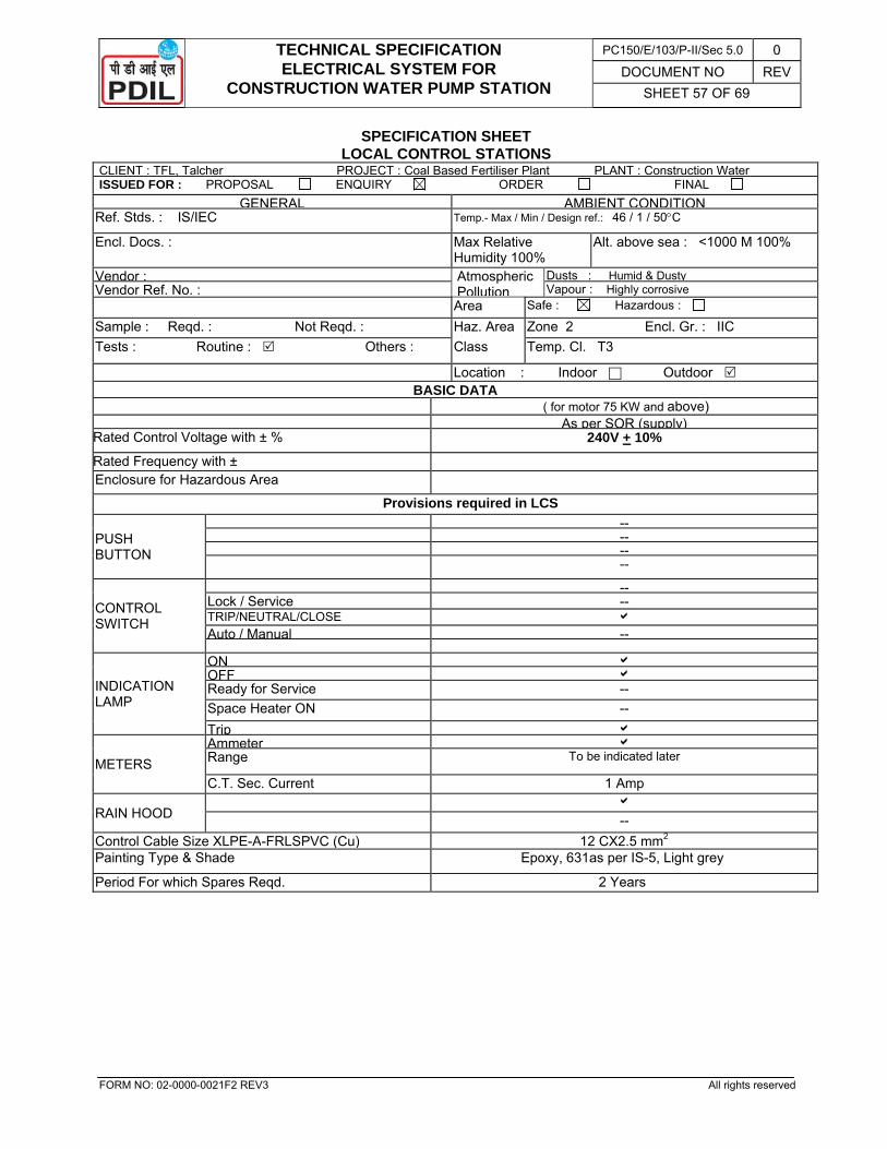
TECHNICAL SPECIFICATION ELECTRICAL SYSTEM FOR
CONSTRUCTION WATER PUMP STATION
PC150/E/103/P-II/Sec 5.0 0 DOCUMENT NO REV
SHEET 57 OF 69
FORM NO: 02-0000-0021F2 REV3 All rights reserved
SPECIFICATION SHEET LOCAL CONTROL STATIONS
CLIENT : TFL, Talcher PROJECT : Coal Based Fertiliser Plant PLANT : Construction Water ISSUED FOR : PROPOSAL ENQUIRY ORDER FINAL
GENERAL AMBIENT CONDITIONRef. Stds. : IS/IEC Temp.- Max / Min / Design ref.: 46 / 1 / 50°C
Encl. Docs. : Max Relative Humidity 100%
Alt. above sea : <1000 M 100%
Vendor : Atmospheric Pollution
Dusts : Humid & Dusty Vendor Ref. No. : Vapour : Highly corrosive Area Safe : Hazardous : Sample : Reqd. : Not Reqd. : Haz. Area
lZone 2 Encl. Gr. : IIC
Tests : Routine : Others : Class Temp. Cl. T3
Location : Indoor Outdoor BASIC DATA
( for motor 75 KW and above) As per SOR (supply)
Rated Control Voltage with ± % 240V + 10% Rated Frequency with ± Enclosure for Hazardous Area
Provisions required in LCS
PUSH BUTTON
--------
CONTROL SWITCH
--Lock / Service -- TRIP/NEUTRAL/CLOSE b Auto / Manual --
INDICATION LAMP
ON bOFF bReady for Service -- Space Heater ON -- Trip b
METERS Ammeter bRange To be indicated later
C.T. Sec. Current 1 Amp
RAIN HOOD b --
Control Cable Size XLPE-A-FRLSPVC (Cu) 12 CX2.5 mm2 Painting Type & Shade Epoxy, 631as per IS-5, Light grey
Period For which Spares Reqd. 2 Years
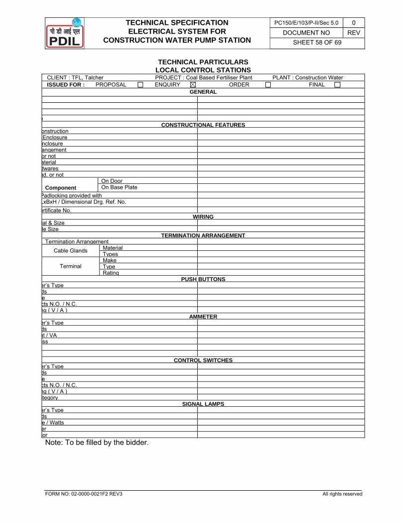
TECHNICAL SPECIFICATION ELECTRICAL SYSTEM FOR
CONSTRUCTION WATER PUMP STATION
PC150/E/103/P-II/Sec 5.0 0 DOCUMENT NO REV
SHEET 58 OF 69
FORM NO: 02-0000-0021F2 REV3 All rights reserved
TECHNICAL PARTICULARS LOCAL CONTROL STATIONS
CLIENT : TFL, Talcher PROJECT : Coal Based Fertiliser Plant PLANT : Construction Water ISSUED FOR : PROPOSAL ENQUIRY ORDER FINAL
GENERAL
e CONSTRUCTIONAL FEATURES
onstruction Enclosure nclosure angement or not aterial dwares qd. or not
Component On Door On Base Plate
Padlocking provided with LxBxH / Dimensional Drg. Ref. No. ertificate No.
WIRINGial & Size le Size
TERMINATION ARRANGEMENTTermination Arrangement
Cable Glands Material Types
Terminal Make Type Rating
PUSH BUTTONSer’s Type ds e cts N.O. / N.C. ng ( V / A )
AMMETERer’s Type ds nt / VA ass
CONTROL SWITCHESer’s Type ds e cts N.O. / N.C. ng ( V / A ) ategory
SIGNAL LAMPSer’s Type ds e / Watts er tor
Note: To be filled by the bidder.
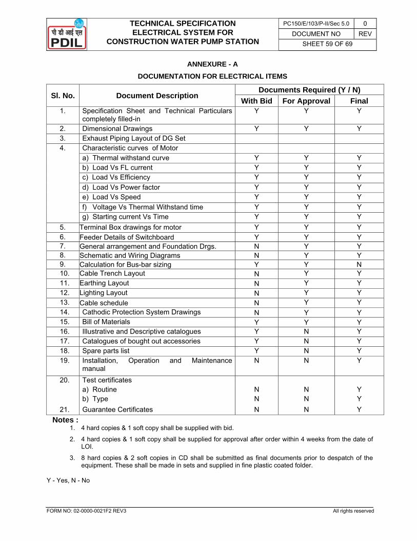
TECHNICAL SPECIFICATION ELECTRICAL SYSTEM FOR
CONSTRUCTION WATER PUMP STATION
PC150/E/103/P-II/Sec 5.0 0 DOCUMENT NO REV
SHEET 59 OF 69
FORM NO: 02-0000-0021F2 REV3 All rights reserved
ANNEXURE - A DOCUMENTATION FOR ELECTRICAL ITEMS
Notes : 1. 4 hard copies & 1 soft copy shall be supplied with bid.
2. 4 hard copies & 1 soft copy shall be supplied for approval after order within 4 weeks from the date of LOI.
3. 8 hard copies & 2 soft copies in CD shall be submitted as final documents prior to despatch of the equipment. These shall be made in sets and supplied in fine plastic coated folder.
Y - Yes, N - No
Sl. No. Document Description Documents Required (Y / N)
With Bid For Approval Final 1. Specification Sheet and Technical Particulars
completely filled-in Y Y Y
2. Dimensional Drawings Y Y Y 3. Exhaust Piping Layout of DG Set 4. Characteristic curves of Motor
a) Thermal withstand curve Y Y Y b) Load Vs FL current Y Y Y c) Load Vs Efficiency Y Y Y d) Load Vs Power factor Y Y Y e) Load Vs Speed Y Y Y f) Voltage Vs Thermal Withstand time Y Y Y g) Starting current Vs Time Y Y Y
5. Terminal Box drawings for motor Y Y Y 6. Feeder Details of Switchboard Y Y Y 7. General arrangement and Foundation Drgs. N Y Y 8. Schematic and Wiring Diagrams N Y Y 9. Calculation for Bus-bar sizing Y Y N 10. Cable Trench Layout N Y Y 11. Earthing Layout N Y Y 12. Lighting Layout N Y Y 13. Cable schedule N Y Y 14. Cathodic Protection System Drawings N Y Y 15. Bill of Materials Y Y Y 16. Illustrative and Descriptive catalogues Y N Y 17. Catalogues of bought out accessories Y N Y 18. Spare parts list Y N Y 19. Installation, Operation and Maintenance
manual N N Y
20. Test certificates a) Routine N N Y b) Type N N Y
21. Guarantee Certificates N N Y
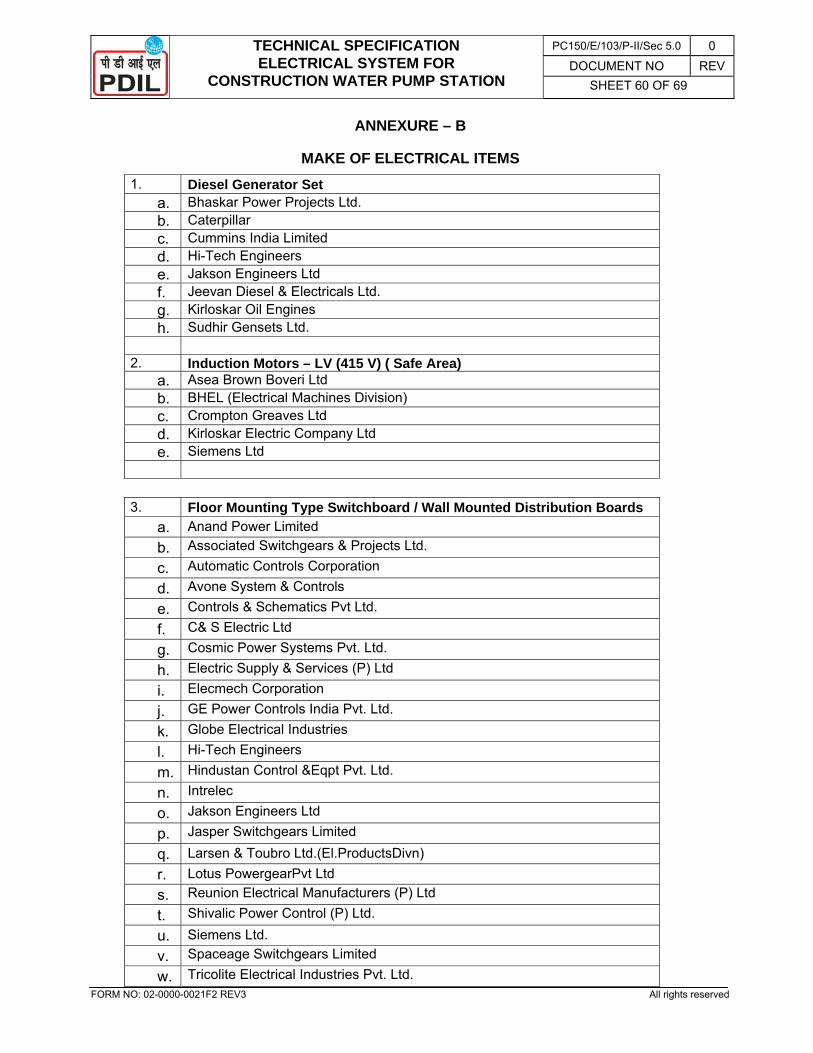
TECHNICAL SPECIFICATION ELECTRICAL SYSTEM FOR
CONSTRUCTION WATER PUMP STATION
PC150/E/103/P-II/Sec 5.0 0 DOCUMENT NO REV
SHEET 60 OF 69
FORM NO: 02-0000-0021F2 REV3 All rights reserved
ANNEXURE – B
MAKE OF ELECTRICAL ITEMS 1. Diesel Generator Set
a. Bhaskar Power Projects Ltd. b. Caterpillar c. Cummins India Limited d. Hi-Tech Engineers e. Jakson Engineers Ltd f. Jeevan Diesel & Electricals Ltd. g. Kirloskar Oil Engines h. Sudhir Gensets Ltd.
2. Induction Motors – LV (415 V) ( Safe Area)
a. Asea Brown Boveri Ltd b. BHEL (Electrical Machines Division) c. Crompton Greaves Ltd d. Kirloskar Electric Company Ltd e. Siemens Ltd
3. Floor Mounting Type Switchboard / Wall Mounted Distribution Boards a. Anand Power Limited b. Associated Switchgears & Projects Ltd.
c. Automatic Controls Corporation
d. Avone System & Controls
e. Controls & Schematics Pvt Ltd.
f. C& S Electric Ltd
g. Cosmic Power Systems Pvt. Ltd.
h. Electric Supply & Services (P) Ltd
i. Elecmech Corporation
j. GE Power Controls India Pvt. Ltd.
k. Globe Electrical Industries
l. Hi-Tech Engineers
m. Hindustan Control &Eqpt Pvt. Ltd.
n. Intrelec
o. Jakson Engineers Ltd
p. Jasper Switchgears Limited
q. Larsen & Toubro Ltd.(El.ProductsDivn) r. Lotus PowergearPvt Ltd s. Reunion Electrical Manufacturers (P) Ltd
t. Shivalic Power Control (P) Ltd. u. Siemens Ltd. v. Spaceage Switchgears Limited
w. Tricolite Electrical Industries Pvt. Ltd.
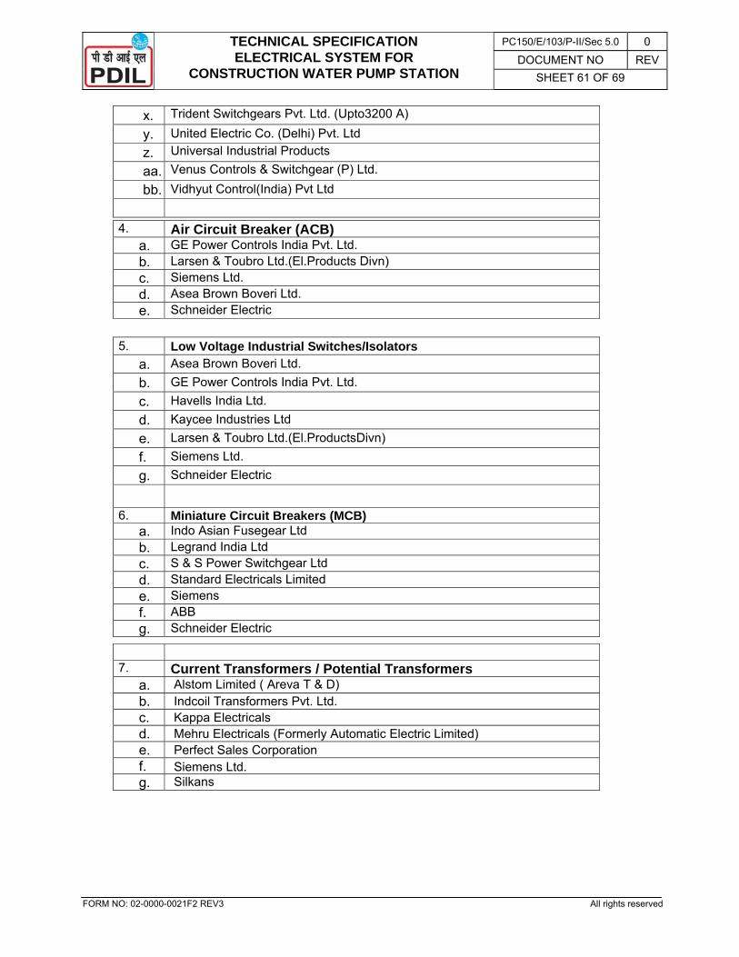
TECHNICAL SPECIFICATION ELECTRICAL SYSTEM FOR
CONSTRUCTION WATER PUMP STATION
PC150/E/103/P-II/Sec 5.0 0 DOCUMENT NO REV
SHEET 61 OF 69
FORM NO: 02-0000-0021F2 REV3 All rights reserved
x. Trident Switchgears Pvt. Ltd. (Upto3200 A)
y. United Electric Co. (Delhi) Pvt. Ltd z. Universal Industrial Products
aa. Venus Controls & Switchgear (P) Ltd.
bb. Vidhyut Control(India) Pvt Ltd
4. Air Circuit Breaker (ACB) a. GE Power Controls India Pvt. Ltd. b. Larsen & Toubro Ltd.(El.Products Divn) c. Siemens Ltd. d. Asea Brown Boveri Ltd. e. Schneider Electric
5. Low Voltage Industrial Switches/Isolators a. Asea Brown Boveri Ltd. b. GE Power Controls India Pvt. Ltd. c. Havells India Ltd. d. Kaycee Industries Ltd e. Larsen & Toubro Ltd.(El.ProductsDivn) f. Siemens Ltd. g. Schneider Electric
6. Miniature Circuit Breakers (MCB) a. Indo Asian Fusegear Ltd b. Legrand India Ltd c. S & S Power Switchgear Ltd d. Standard Electricals Limited e. Siemens f. ABB g. Schneider Electric
7. Current Transformers / Potential Transformers
a. Alstom Limited ( Areva T & D) b. Indcoil Transformers Pvt. Ltd. c. Kappa Electricals d. Mehru Electricals (Formerly Automatic Electric Limited) e. Perfect Sales Corporation f. Siemens Ltd. g. Silkans
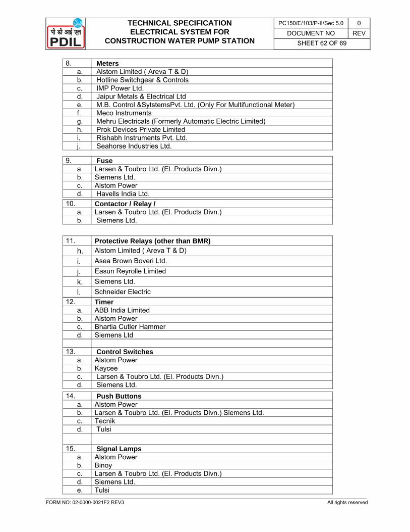
TECHNICAL SPECIFICATION ELECTRICAL SYSTEM FOR
CONSTRUCTION WATER PUMP STATION
PC150/E/103/P-II/Sec 5.0 0 DOCUMENT NO REV
SHEET 62 OF 69
FORM NO: 02-0000-0021F2 REV3 All rights reserved
8. Meters a. Alstom Limited ( Areva T & D) b. Hotline Switchgear & Controls c. IMP Power Ltd. d. Jaipur Metals & Electrical Ltd e. M.B. Control &SytstemsPvt. Ltd. (Only For Multifunctional Meter) f. Meco Instruments g. Mehru Electricals (Formerly Automatic Electric Limited) h. Prok Devices Private Limited i. Rishabh Instruments Pvt. Ltd. j. Seahorse Industries Ltd.
9. Fuse a. Larsen & Toubro Ltd. (El. Products Divn.) b. Siemens Ltd. c. Alstom Power d. Havells India Ltd.
10. Contactor / Relay / a. Larsen & Toubro Ltd. (El. Products Divn.) b. Siemens Ltd.
11. Protective Relays (other than BMR) h. Alstom Limited ( Areva T & D) i. Asea Brown Boveri Ltd. j. Easun Reyrolle Limited k. Siemens Ltd. l. Schneider Electric
12. Timer a. ABB India Limited b. Alstom Power c. Bhartia Cutler Hammer d. Siemens Ltd
13. Control Switches
a. Alstom Power b. Kaycee c. Larsen & Toubro Ltd. (El. Products Divn.) d. Siemens Ltd.
14. Push Buttons a. Alstom Power b. Larsen & Toubro Ltd. (El. Products Divn.) Siemens Ltd. c. Tecnik d. Tulsi
15. Signal Lamps
a. Alstom Power b. Binoy c. Larsen & Toubro Ltd. (El. Products Divn.) d. Siemens Ltd. e. Tulsi
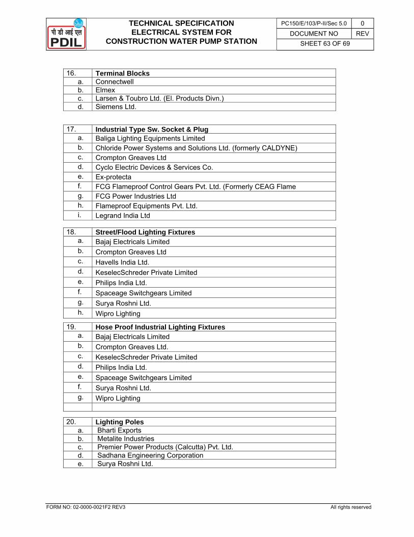
TECHNICAL SPECIFICATION ELECTRICAL SYSTEM FOR
CONSTRUCTION WATER PUMP STATION
PC150/E/103/P-II/Sec 5.0 0 DOCUMENT NO REV
SHEET 63 OF 69
FORM NO: 02-0000-0021F2 REV3 All rights reserved
16. Terminal Blocks a. Connectwell b. Elmex c. Larsen & Toubro Ltd. (El. Products Divn.) d. Siemens Ltd.
17. Industrial Type Sw. Socket & Plug a. Baliga Lighting Equipments Limited b. Chloride Power Systems and Solutions Ltd. (formerly CALDYNE) c. Crompton Greaves Ltd d. Cyclo Electric Devices & Services Co. e. Ex-protecta f. FCG Flameproof Control Gears Pvt. Ltd. (Formerly CEAG Flame g. FCG Power Industries Ltd h. Flameproof Equipments Pvt. Ltd. i. Legrand India Ltd
18. Street/Flood Lighting Fixtures a. Bajaj Electricals Limited b. Crompton Greaves Ltd c. Havells India Ltd. d. KeselecSchreder Private Limited e. Philips India Ltd. f. Spaceage Switchgears Limited g. Surya Roshni Ltd. h. Wipro Lighting
19. Hose Proof Industrial Lighting Fixturesa. Bajaj Electricals Limited b. Crompton Greaves Ltd. c. KeselecSchreder Private Limited d. Philips India Ltd. e. Spaceage Switchgears Limited f. Surya Roshni Ltd. g. Wipro Lighting
20. Lighting Poles a. Bharti Exports b. Metalite Industries c. Premier Power Products (Calcutta) Pvt. Ltd. d. Sadhana Engineering Corporation e. Surya Roshni Ltd.
TECHNICAL SPECIFICATION ELECTRICAL SYSTEM FOR
CONSTRUCTION WATER PUMP STATION
PC150/E/103/P-II/Sec 5.0 0 DOCUMENT NO REV
SHEET 64 OF 69
FORM NO: 02-0000-0021F2 REV3 All rights reserved
21. LT Power Cables / LT Control Cables a. Cable Corpn. of India Limited b. Cords Cable Industries Ltd c. Delton Cables Ltd d. Finolex Cables Ltd e. KEC International Ltd. (Formerly RPG Cables Limited f. KEI Industries Limited g. Nicco Corporation Ltd h. Plaza Cable Industries Limited i. Ravin Cables Limited j. Torrent Cables Ltd k. Universal Cables Ltd. l. Polycab
22. Cables For Earthing a. Advance Cable Technologies (P) Ltd. b. Delton Cables Ltd c. Finolex Cables Ltd d. Gupta Electric & Machinery Stores (GEMSCAB) e. J K Cables Limited f. Netco Cable Industries (Pvt.) Ltd. g. Nicco Corporation Ltd h. Prestige Cable Industries i. Shyam Cables Industries j. Special Cables Pvt. Ltd. k. T C Communication Pvt Ltd l. Universal Cables Ltd.
23. Pre-Fabricated G.I. Cable Traysa. Globe Electrical Industries b. Indiana Engg Works Pvt Ltd c. IndmarkFormtech Pvt. Ltd. d. Jamna Metal Company e. KanadeAnandUdyog Pvt. Ltd. f. Maheshwari Electrical Mfrs. (P) Ltd. g. Metalite Industries h. Parekh Engineering Company i. Premier Power Products (Calcutta) Pvt. Ltd. j. Rukmani Electricals & Components Pvt Ltd k. Sadhana Engineering Corporation l. Slotco Steel products Pvt. Ltd. m. SreeAtreya Enterprises n. StealiteEngg Co
TECHNICAL SPECIFICATION ELECTRICAL SYSTEM FOR
CONSTRUCTION WATER PUMP STATION
PC150/E/103/P-II/Sec 5.0 0 DOCUMENT NO REV
SHEET 65 OF 69
FORM NO: 02-0000-0021F2 REV3 All rights reserved
24. FRP Cable Trays a. Enercon b. Ercon Composites (Upto 600 Mm Wide) c. Kemrock d. Satyam Industries e. Sintex Industries Ltd. f. Sumip Composites Pvt Ltd.
25. Hose Proof Local Control Station a. Baliga Lighting Equipments Limited b. Bhartia Industries Ltd. (Divn. Bch) c. C & S Electric Ltd. d. Ex-Protecta e. FCG Flameproof Control Gears Pvt. Ltd. (Formerly CEAG Flame) f. FCG Power Industries Ltd. g. Flameproof Equipments Pvt. Limited h. Hotline Switchgear & Controls i. Power Engg Co
26. Hose proof Junction Boxes
a. Baliga Lighting Equipments Limited b. Bhartia Industries Ltd. (Divn. Bch) c. Ex-protecta d. FCG Flameproof Control Gears Pvt. Ltd. (Formerly CEAG Flame) e. Flameproof EquipmentsPvt. Ltd. f. FCG Power Industries Ltd
27. Earthing & Lightning Protection Material – (GI) Wire/Stripa. Anand Electric Trading Co. b. Controls & Switchgear Co. Ltd. c. Jayant Metal Mfg. Co. d. IndmarkFormtech Pvt. Ltd. e. Premier Power Products (Calcutta) Pvt. Ltd. f. Jamna Metal Co. g. Mahavir Industrial Corporation h. Metropolitan Industries i. Sai Galvanisers & Fabricators Pvt Ltd j. Bharti Exports k. Metalite Industries l. Rukmani Electricals & Components Pvt Ltd m. Sadhana Engineering Corporation n. StealiteEngg Co
TECHNICAL SPECIFICATION ELECTRICAL SYSTEM FOR
CONSTRUCTION WATER PUMP STATION
PC150/E/103/P-II/Sec 5.0 0 DOCUMENT NO REV
SHEET 66 OF 69
FORM NO: 02-0000-0021F2 REV3 All rights reserved
28. GI Pipes & Conduits a. Bharti Exports b. Indian Tube Co. (Tata Div. of Tubes & Pipes) c. Jindal Pipes Ltd. d. Meghjyot Enterprises e. Rukmani Electricals & Components Pvt Ltd f. Steelcraft
29. Industrial Cable Glanda. Baliga Lighting Equipments Limited b. Comet Brass Products c. Comet Industries d. Dowell's Electricals e. Electromac Industries f. FCG Flameproof Control Gears Pvt. Ltd. (Formerly CEAG Flame g. Gland-Mech. Industries h. Industrial products Equipment i. Power Engg Co j. Quality & Precision Indl. Equipment k. S J Metal Industries (Jainson)
30. Cable Lugs
a. Dowell's Electricals b. Forward Engg Industries c. KSE Electrical Pvt. Ltd. d. MG Electrica e. Power Engg Co f. S J Metal Industries (Jainson) g. Usha Martin Industries Ltd. (IsmalDivn)
31. Cathodic Protection a. M/s Raychem RPG Ltd b. M/s Consultech c. M/s Afcons Corrosion protection Pvt Ltd (Formerly SSS Electricals (I) Pvt
Ltd.) d. M/s Corrosion Control Services (Bombay) Pvt Ltd e. M/s Corrtech, Ahmedabad f. M/s CTS Private Limited g. M/s Corrtech International Pvt Ltd h. SARK EPC Projects pvt. Ltd.
32. Transfer Rectifier unit a. Advance Electronic Systems b. Raychem c. Canara Eelctricals d. Corrpro Systems e. Kristons Systems
TECHNICAL SPECIFICATION ELECTRICAL SYSTEM FOR
CONSTRUCTION WATER PUMP STATION
PC150/E/103/P-II/Sec 5.0 0 DOCUMENT NO REV
SHEET 67 OF 69
FORM NO: 02-0000-0021F2 REV3 All rights reserved
33. Test Stations/ Anode Junction Box/ Cathode Junction Box / Surge Arrestor Junction Box/ Reference Electrode Junction Box (REJB) / Earthing Junction Box (EJB)
a. Corrpro Systems b. Advance Electronic Systems c. FCG d. FEPL e. Flexpro f. Baliga
34. Permanent Reference Electrode ) a. Advance Electronic Systems b. Borin, USA c. M C Miller, USA d. Cer Anode, USA e. Harco, USA f. Advance Electronic Systems, USA
35. Surge Diverter for MIJS a. Advance Electronic Systems b. DEHN, Germany c. Hockway, Germany d. OBO Betterman, Germany, Germany
36. Monolithic Isolating Joints a. Advance Electronic Systems b. Alfa Engineering c. SRL Italy d. Zunt Italy e. RMA Italy f. Advance Products, USA
37. Calcined Petroleum Coke Breeze a. Goa Carbon b. India Carbon (Calcutta) c. Petro Carbon & Chem. Company
38. Zinc Grounding Electrode/ Cell/ Zinc Ribbon Anode Magnesium Anodes (For TCP)
a. Sargam Metals Chennai b. Advance Electronic Systems c. Corrpro Systems d. Scientific Metals Karaikudi e. Corrtech Metals
39. Deep Anode Ground Bed (MMO type) a. Corrpro System b. Ceranode, USA c. LIDA d. Titanor Components e. Berry Plastic, USA f. Mactor, USA
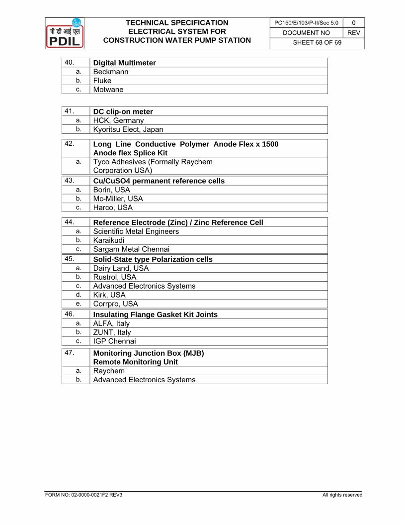
TECHNICAL SPECIFICATION ELECTRICAL SYSTEM FOR
CONSTRUCTION WATER PUMP STATION
PC150/E/103/P-II/Sec 5.0 0 DOCUMENT NO REV
SHEET 68 OF 69
FORM NO: 02-0000-0021F2 REV3 All rights reserved
40. Digital Multimeter a. Beckmann b. Fluke c. Motwane
41. DC clip-on meter a. HCK, Germany b. Kyoritsu Elect, Japan
42. Long Line Conductive Polymer Anode Flex x 1500 Anode flex Splice Kit
a. Tyco Adhesives (Formally Raychem Corporation USA)
43. Cu/CuSO4 permanent reference cells a. Borin, USA b. Mc-Miller, USA c. Harco, USA
44. Reference Electrode (Zinc) / Zinc Reference Cell a. Scientific Metal Engineers b. Karaikudi c. Sargam Metal Chennai
45. Solid-State type Polarization cells a. Dairy Land, USA b. Rustrol, USA c. Advanced Electronics Systems d. Kirk, USA e. Corrpro, USA
46. Insulating Flange Gasket Kit Joints a. ALFA, Italy b. ZUNT, Italy c. IGP Chennai
47. Monitoring Junction Box (MJB) Remote Monitoring Unit
a. Raychem b. Advanced Electronics Systems
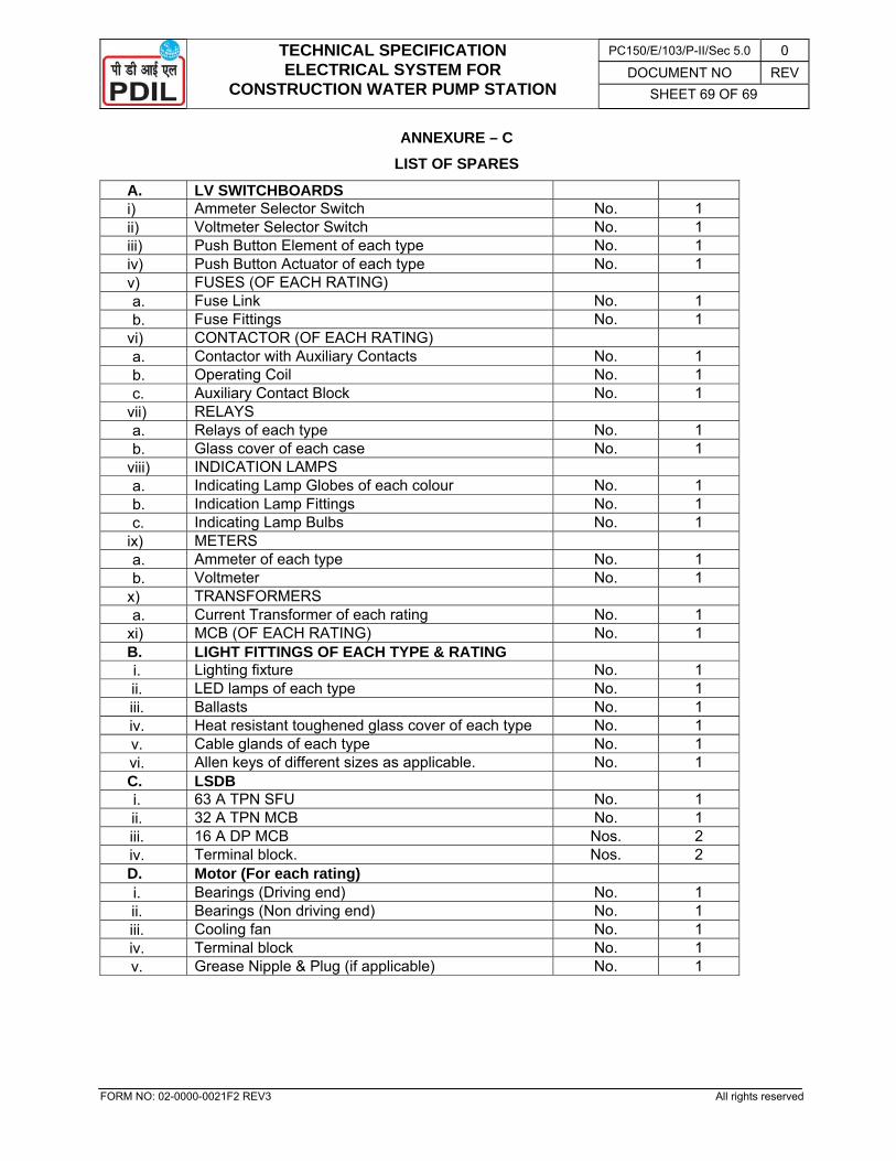
TECHNICAL SPECIFICATION ELECTRICAL SYSTEM FOR
CONSTRUCTION WATER PUMP STATION
PC150/E/103/P-II/Sec 5.0 0 DOCUMENT NO REV
SHEET 69 OF 69
FORM NO: 02-0000-0021F2 REV3 All rights reserved
ANNEXURE – C
LIST OF SPARES
A. LV SWITCHBOARDS i) Ammeter Selector Switch No. 1 ii) Voltmeter Selector Switch No. 1 iii) Push Button Element of each type No. 1 iv) Push Button Actuator of each type No. 1 v) FUSES (OF EACH RATING) a. Fuse Link No. 1 b. Fuse Fittings No. 1
vi) CONTACTOR (OF EACH RATING) a. Contactor with Auxiliary Contacts No. 1 b. Operating Coil No. 1 c. Auxiliary Contact Block No. 1
vii) RELAYS a. Relays of each type No. 1 b. Glass cover of each case No. 1
viii) INDICATION LAMPS a. Indicating Lamp Globes of each colour No. 1 b. Indication Lamp Fittings No. 1 c. Indicating Lamp Bulbs No. 1
ix) METERS a. Ammeter of each type No. 1 b. Voltmeter No. 1
x) TRANSFORMERS a. Current Transformer of each rating No. 1
xi) MCB (OF EACH RATING) No. 1 B. LIGHT FITTINGS OF EACH TYPE & RATING i. Lighting fixture No. 1 ii. LED lamps of each type No. 1 iii. Ballasts No. 1 iv. Heat resistant toughened glass cover of each type No. 1 v. Cable glands of each type No. 1 vi. Allen keys of different sizes as applicable. No. 1 C. LSDB i. 63 A TPN SFU No. 1 ii. 32 A TPN MCB No. 1 iii. 16 A DP MCB Nos. 2 iv. Terminal block. Nos. 2 D. Motor (For each rating) i. Bearings (Driving end) No. 1 ii. Bearings (Non driving end) No. 1 iii. Cooling fan No. 1 iv. Terminal block No. 1 v. Grease Nipple & Plug (if applicable) No. 1
![ASSESSMENT OF CLASS OF WATER IN RIVER BRAHMANI, …ijesr.org/admin/upload_journal/journal_Bhagirathi 2se18sr.pdf · branches[4]. The left branch is called Brahmani main and the right](https://img.pdfslide.us/doc/110x75/5e696200917b5c67994fd5f8/assessment-of-class-of-water-in-river-brahmani-ijesrorgadminuploadjournaljournalbhagirathi.jpg)


![cathodic protection in practise · 2 [CATHODIC PROTECTION/BM] CATHODIC PROTECTION P E FRANCIS 1 INTRODUCTION The first practical use of cathodic protection is generally credited to](https://img.pdfslide.us/doc/110x75/5ace93c87f8b9ae2138b87e4/cathodic-protection-in-cathodic-protectionbm-cathodic-protection-p-e-francis.jpg)