Embed Size (px)
Citation preview

Fairbanks, Alaska
April 2015
PROJECTING PHYSICAL OBJECTS INTO A VIRTUAL SPACE USIN G THE KINECT AND OCULU S RIFT
A Project
By Shaun P. Bond
Presented to the Faculty of the University of Alaska Fairbanks
In Partial Fulfillment of the Requirements of
MASTER OF SCIENCE IN COMPUTER SCIENCE

Page 2
PROJECTING PHYSICAL OBJECTS INTO A VIRTUAL SPACE USIN G THE KINECT AND OCULU S RIFT
A Project
By Shaun P. Bond
RECOMMENDED:
______________________________________________________
Advisory Committee Chair Date
______________________________________________________
Advisory Committee Member Date
______________________________________________________
Advisory Committee Member Date
APPROVED:
______________________________________________________
Dept. Head, Computer Science Department Date

Page 3
ABSTRACT
Virtualized Reality as a field of research has been increasing over the last couple of decades. Initially, it required large camera arrays, expensive equipment, and custom software to implement a virtualized reality system. With the release of the Kinect and the Oculus Rift development kits, however, the average person now has the potential to acquire the hardware and software needed to implement a virtualized reality system. This project explores the possibility of using the Kinect and Oculus Rift together to display geometry based on real-world objects in a virtual environment.

Page 4
ACKNOWLEDGEMENTS
Special thanks to Dr. Orion Lawlor, Dr. Glenn Chappell, and Dr. John Genetti for their guidance, technical support, and assistance during my completion of the Master’s program and this project report. I would also like to thank Connie Huizenga for always being helpful, the Department of Computer Science at the University of Alaska Fairbanks for providing me with this opportunity, all of my professors for being awesome professors and imparting their knowledge to me, and Ayse Yeager for her personal support.

Page 5
TABLE OF CONTENTS
Abstract ....................................................................................................................................................................................... 3
Acknowledgements ................................................................................................................................................................ 4
Table of Figures ........................................................................................................................................................................ 6
Introduction ............................................................................................................................................................................... 7
Hardware .................................................................................................................................................................................... 9
Converting Kinect Depth to 3D Geometry ................................................................................................................... 12
Rendering With the Oculus Rift ....................................................................................................................................... 15
Integrating Oculus Rift and Kinect ................................................................................................................................. 17
Performance ............................................................................................................................................................................ 21
Future Research ..................................................................................................................................................................... 22
References ................................................................................................................................................................................ 23

Page 6
TABLE OF FIGURES
Figure 1: VEVI Interface (Hine, 1994) ............................................................................................................................. 7 Figure 2: The Dome at Carnegie Mellon University (Copyright Carnegie Mellon, 1995) .......................... 8 Figure 3: 3rd person perspective point cloud (Property of Johnathan Ota) ................................................... 8 Figure 4: Kinect for Xbox 360 (Photograph: Michal Czerwonka/Getty Images) .......................................... 9 Figure 5: IR dot pattern emitted by the Kinect ......................................................................................................... 10 Figure 6: Distortion caused by lenses in Oculus Rift............................................................................................... 11 Figure 7: Chromatic aberration ....................................................................................................................................... 11 Figure 8: Near-infrared LEDs in Oculus Rift (Terndrup, 2014) ......................................................................... 11 Figure 9: Output of unmodified cpp_view ................................................................................................................... 12 Figure 10: Stephane Magnenat's depth to distance conversion (OpenKinect, 2013) ............................... 13 Figure 11: Dr. Lawlor's code for 2D to 3D projection ............................................................................................. 13 Figure 12: Modified cpp_view showing generated point cloud .......................................................................... 14 Figure 13: Algorithm for generating triangle strip .................................................................................................. 14 Figure 14: Modified cpp_view showing triangle strip with discarded triangles ......................................... 15 Figure 15: Simple cube rendered in stereo to standard display ........................................................................ 16 Figure 16: Real world geometry rendered on the Oculus Rift ............................................................................ 17 Figure 17: RGB image applied to geometry without correction ........................................................................ 18 Figure 18: FOV and distance between cameras accounted for when applying texture ........................... 19 Figure 19: Scene rendered with geometry averaged over 2 Kinect frames .................................................. 20 Figure 20: Scene rendered with virtual lighting removed from real-world geometry............................. 20 Figure 21: Performance of Rendering and Kinect image processing ............................................................... 21

Page 7
INTRODUCTION
Virtualized reality can be viewed as the complement to augmented reality. In augmented
reality, computer generated visuals are integrated with real world visuals. In virtualized reality, a
computer generated representation of real world objects is viewed in a virtual reality
environment.
Virtualized reality has applications in many fields. It has been applied in research
involving remotely controlled robotics (Hine, 1994; Goza, 2004)), entertainment (Carnegie
Mellon, 2001), and physical and mental rehabilitation (Thin, 2012). It also has potential for
other applications such as microscopic visualization, training, engineering, architecture, and
others.
Virtualized reality has been a field of research since as early as 1994, when Hine et al.
developed a system to aid in the remote navigation of an underwater vehicle. This system used
sensory data from the vehicle’s stereo cameras, and positional data to reconstruct the underwater
environment. It also supported two display modes, one of which was a VR headset. Once the
environmental data was collected, the operator could navigate from within the virtual
environment relatively free from communication latency (Hine, 1994).
FIGURE 1: VEVI INTERFACE (HINE, 1994)
In 1995, Kanade et al. developed a virtualized reality system utilizing a large camera
array (Kanade, 1995). This camera array recorded video from various perspectives, which was
later used to construct a 3 dimensional video. This allowed the viewer to select an arbitrary
viewpoint during playback (Kanade, 1997). Later, in 2001, a version of this system was used to
record a Super Bowl event (Carnegie Mellon, 2001).

Page 8
FIGURE 2: THE DOME AT CARNEGIE MELLON UNIVERSITY (COPYRIGHT CARNEGIE MELLON, 1995)
More recently, some students at Carnegie Mellon University created a virtualized reality
system that allows a person to explore the world from a third person perspective (Ota, no date).
This system utilizes the Kinect’s depth sensor to gather environmental information, and the
Oculus Rift head mounted display to view it. The Kinect is mounted at a fixed position relative
to the user, giving the third person perspective to the viewer.
FIGURE 3: 3RD PERSON PERSPECTIVE POINT CLOUD (PROPERTY OF JOHNATHAN OTA)

Page 9
I wanted to explore whether real time virtualized reality was feasible on commodity
hardware. My goals for this project were to use the Microsoft Kinect to generate a 3D triangle
mesh of real world objects, place the mesh in a virtual environment, and display it to the Oculus
Rift in real-time. Some projects I have found produce a triangle mesh in real time, but do not
display it in stereoscopic VR (Izadi, 2011). Others (Ota, no date), display data from the Kinect
in stereoscopic VR, but use a simple point-based rendering approach instead of a continuous
triangle mesh. My project differs from these in that it does both.
HARDWARE
The Kinect is a device developed by the Microsoft Corporation to allow motion input for
video games, but researchers have found many other uses for its depth detection and motion
tracking capabilities. Among these are 3D reconstruction of objects (Izadi, 2011), translation of
sign language (Microsoft, 2013), and hands free control of operating room computers (Brigley,
no date). The original Kinect was designed for use with the Xbox 360, but there are newer
versions available for Xbox One and personal computers. I used the original Xbox 360 version
in my project, so the hardware and software specifications in this paper refer to that version.
The Kinect device consists of an infrared (IR) emitter, IR receiver, and color (RGB)
camera. The IR emitter and receiver are located approximately 7.5 cm apart, and the IR emitter
projects a predefined dot pattern (Freedman, 2012). This dot pattern bounces off of IR reflective
objects and is acquired by the IR receiver. The Kinect analyzes the parallax shift and distortion
of the pattern to build a two dimensional matrix of depth values hereafter referred to as the depth
image. The dot pattern can be seen in figure 5.
FIGURE 4: KINECT FOR XBOX 360 (PHOTOGRAPH: MICHAL CZERWONKA/GETTY IMAGES)

Page 10
FIGURE 5: IR DOT PATTERN EMITTED BY THE KINECT
The Oculus Rift is a virtual reality headset in development by Oculus VR. As of this
paper, they have released two versions. These are referred to as Development Kit 1 (DK1), and
Development Kit 2 (DK2). The DK2 possesses a higher resolution and reduced latency over the
DK1, as well as the addition of positional tracking. The DK2 is the version I used for this
project, so the specifications here refer to that version.
The DK2 has a single display and two eyepieces. The display has a 1920 x 1080 pixel
resolution, and 2 milliseconds of persistence. The low persistence provides better immersion and
reduced motion sickness by reducing motion blur. The optical lenses in the eyepieces have a 100
degree field of view, which allows for greater peripheral vision. However, the large field of
view causes distortion of the image, which needs to be corrected. Another problem caused by
the lenses is chromatic aberration, which must also be accounted for when rendering. These
effects can be seen in figures 6 and 7. In order to achieve position and orientation tracking, the
DK2 possesses an internal accelerometer, magnetometer, and gyroscope, as well as an external
position tracking camera. The internal sensors update 1000 times per second, while the position
tracking camera updates 60 times per second. All of the sensors communicate with the computer
over a USB 2.0 connection, while the display is transmitted over an HDMI connection.
Stereoscopic vision is achieved by drawing a scene from two different perspectives, that
of the left eye and that of the right eye. Each of these images is drawn on one half of the DK2
display and the eyepieces are focused on their respective halves. Chromatic aberration and lens
distortion are handled in software prior to displaying the scene. The image is predistorted and
chromatic aberration is applied in reverse. When the image passes through the lens, the effects
are undone. This avoids the necessity for expensive hardware solutions.

Page 11
The DK2 handles position tracking by using near-infrared LEDs placed on the headset.
Each of these LEDs emit at a different frequency and intensity (Terndrup, 2014). This allows the
position tracking software to identify which LED a signal came from, and calculate the position
of the headset. The distance of the headset from the camera can be determined by the relative
spacing of the LEDs. The vertical and horizontal position can be found in a straightforward
manner using the 2D position of an LED and its distance from the camera.
FIGURE 8: NEAR-INFRARED LEDS IN OCULUS RIFT (TERNDRUP, 2014)
FIGURE 6: DISTORTION CAUSED BY LENSES IN OCULUS RIFT FIGURE 7: CHROMATIC ABERRATION

Page 12
CONVERTING KINECT DEPTH TO 3D GEOMETRY
My first step for this project was to produce a 3D geometry from a Kinect depth image.
To interface with the Kinect, I used an open source library called Libfreenect. Libfreenect
defines the FreenectDevice base class, which is responsible for communicating with the Kinect
device. A user then derives a class from FreenectDevice and overloads functions to receive
video frames and perform any desired computation. FreenectDevice also contains functionality
enabling the user to control the Kinect motor and LEDs.
The Kinect supports RGB, YUV, Bayer, and infrared (IR) image formats for its color
video stream. RGB and Bayer can be returned in 640x480 or 1280x960 pixel resolutions. YUV
and IR formats can only be returned in 640x480 pixel resolution. The user can request any of
these formats and resolutions with Libfreenect. I used the 640x480 RGB resolution, which
allows a maximum of 30 frames per second.
Because the focus of this project was doing the actual transformation, rather than building
the infrastructure, I opted to start with an existing program that would handle all of the setup and
receive images from the Kinect. The program I selected for this purpose is called cpp_view, a
demo program that is part of the Libfreenect project. It receives frames from both the RGB and
depth cameras, does some basic colorization of the depth image, and displays both images to the
screen. Figure 9 shows the output of the original program. It also supports switching between
the various image formats, adjusting the tilt of the Kinect, and operating the LEDs on the Kinect.
FIGURE 9: OUTPUT OF UNMODIFIED CPP_VIEW . LEFT: DEPTH STREAM . RIGHT: RGB STREAM SHOWING IR.
Initially, I would get terminal errors intermittently when starting the program. I would
also receive a terminal error consistently when exiting the program. After reviewing the code, I
noticed that video streams from the Kinect were being initialized during the startup sequence, but
were never stopped. Stopping the video streams in the destructor of the class derived from
FreenectDevice solved both problems. It is my belief that the Kinect was attempting to continue
writing to a buffer after it had been destroyed.

Page 13
In order to familiarize myself with the program and how it handled images, I modified
the code so that it would display a gray-scale coloring of the depth image instead of a color one.
I then added code to the same routine that calculates the 3D position of each pixel in the depth
image and stores it in a vertex array. To assist with this, I used some code written previously by
Dr. Lawlor to project a 2D point into 3D space. The Kinect does not record depth in any
standard unit. Fortunately, Stephane Magnenat developed an algorithm that converts the depth
value to meters with less than 3% error.
FIGURE 10: STEPHANE MAGNENAT'S DEPTH TO DISTANCE CONVERSION (OPENKINECT , 2013)
FIGURE 11: DR . LAWLOR'S CODE FOR 2D TO 3D PROJECTION
I needed to verify that my code was really producing a 3D point cloud with reasonable
values. For the purposes of this project, it is more important that the results are visually
convincing than it is that they are accurate, so I decided that the easiest way to verify was to
display the point cloud along with the colorized depth image, as seen in figure 12. In order to do
this, I replaced the RGB image with the point cloud, but this presented some difficulties. The
Kinect uses a downward pointing y-axis, while OpenGL uses an upward pointing y-axis. The
original code corrects this by flipping the projection coordinates, but Dr. Lawlor's code corrects
the y-axis for the point cloud when the point coordinates are calculated. This resulted in the
point cloud being displayed upside down. I corrected this issue by using two different viewports
with two different projections. This also allowed me to display the point cloud in perspective,
yielding a more convincing image, while not subjecting the depth image to perspective
distortion.
distance = 0.1236 * tan(rawDisparity / 2842.5 + 1.1863)
vec3 loc(int x,int y) const {
return dir(x,y)*depth(x,y);
}
vec3 dir(int x,int y) const {
return vec3((x-w*0.5)*pixelFOV, (h*0.5-y)*pixelFOV, 1);
}
float depth(int x,int y) const {
uint16_t disp=depthi[y*w+x];
if (disp>= INVALID_DEPTH) return 0.0;
return 0.1236 * tan(disp / 2842.5 + 1.1863) - 0.037;
}
pixelFOV=tan(0.5 * (M_PI / 180.0) * 57.8)/(w*0.5);

Page 14
FIGURE 12: MODIFIED CPP_VIEW SHOWING GENERATED POINT CLOUD
Initially, I connected all of the points into a single triangle strip using a simple algorithm
illustrated in figure 13. Unfortunately, the Kinect does not always know the depth at a given
pixel. In those cases, it will return the value 2047, marking it as too far, too close, or otherwise
unknown. Because I assumed that every pixel was a point so that I could implement this
simplified triangle strip algorithm, my code assigned
coordinates to invalid pixels as well. By default, Dr.
Lawlor’s code gave the coordinates (0, 0, 0) to pixels
with an invalid depth. The consequence of this was
that the triangle strip contained triangles connected to
the origin, producing an image that was obviously not
correct. Rather than attempt to implement an
algorithm that did not include these invalid points in
the triangle strip, and could have potentially been far
more complex, this problem can be solved efficiently
using a geometry shader. The coordinates (0, 0, 0) are
the location of the Kinect device itself. Therefore no
point seen by the Kinect could have those coordinates,
which is why it works for invalid points. Using this, I
was able to write a geometry shader that checks each
triangle for a point containing those coordinates. If the shader finds such a point, it discards the
whole triangle. This produces an object that is much more visually convincing, leaving holes
where the Kinect is unable to obtain information. Figure 14 shows the resulting geometry. This
also has the advantage that it runs on the graphics card, so it doesn’t use any more of the CPUs
resources, and it is able to exploit the GPUs massive parallelization.
One other drawback of this algorithm is that it produces a triangle strip that is not well
suited to spherical surfaces and some other shapes. However, this did not seem to make a
noticeable impact on the appearance of the geometry, probably because of the extremely small
size of the individual triangles. Therefore, I did not feel it was worth my time to create a more
complicated algorithm.
FIGURE 13: ALGORITHM FOR GENERATING
TRIANGLE STRIP . CIRCLES REPRESENT VERTICES, ARROWS REPRESENT THE ORDER IN WHICH THEY
ARE ADDED , AND DOTTED LINES REPRESENT THE
IMPLICIT COMPLETION OF A TRIANGLE.
Page 15
FIGURE 14: MODIFIED CPP_VIEW SHOWING TRIANGLE STRIP WITH DISCARDED TRIANGLES
RENDERING WITH THE OCULUS RIFT
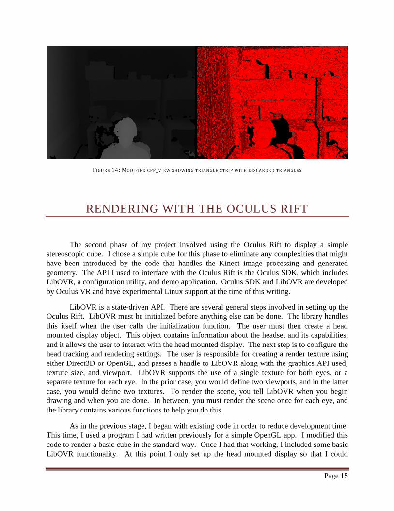
The second phase of my project involved using the Oculus Rift to display a simple
stereoscopic cube. I chose a simple cube for this phase to eliminate any complexities that might
have been introduced by the code that handles the Kinect image processing and generated
geometry. The API I used to interface with the Oculus Rift is the Oculus SDK, which includes
LibOVR, a configuration utility, and demo application. Oculus SDK and LibOVR are developed
by Oculus VR and have experimental Linux support at the time of this writing.
LibOVR is a state-driven API. There are several general steps involved in setting up the
Oculus Rift. LibOVR must be initialized before anything else can be done. The library handles
this itself when the user calls the initialization function. The user must then create a head
mounted display object. This object contains information about the headset and its capabilities,
and it allows the user to interact with the head mounted display. The next step is to configure the
head tracking and rendering settings. The user is responsible for creating a render texture using
either Direct3D or OpenGL, and passes a handle to LibOVR along with the graphics API used,
texture size, and viewport. LibOVR supports the use of a single texture for both eyes, or a
separate texture for each eye. In the prior case, you would define two viewports, and in the latter
case, you would define two textures. To render the scene, you tell LibOVR when you begin
drawing and when you are done. In between, you must render the scene once for each eye, and
the library contains various functions to help you do this.
As in the previous stage, I began with existing code in order to reduce development time.
This time, I used a program I had written previously for a simple OpenGL app. I modified this
code to render a basic cube in the standard way. Once I had that working, I included some basic
LibOVR functionality. At this point I only set up the head mounted display so that I could

Page 16
access sensor data. I did not initialize the rendering configuration because I was not ready to
render to the Oculus Rift yet. I then used the head mounted display’s reported interpupillary
distance to shift the camera and render two images in stereo. I displayed both of these images
side-by-side to the standard display so that I could visually verify that stereo rendering was
working before introducing possible complexities with the head mounted display.
FIGURE 15: SIMPLE CUBE RENDERED IN STEREO TO STANDARD DISPLAY
The next step was to display the cube on the headset. For this step, I needed to initialize
the LibOVR rendering configuration. Actually getting LibOVR to do the rendering was as
simple as replacing my call to swap the display buffers with the library’s equivalent. Because I
set it up in the rendering configuration, LibOVR handled distortion correction and chromatic
aberration correction for me. The final step in this stage was to incorporate head tracking. This
involved querying the head mounted display for its position and orientation, and constructing
view and projection matrices using that information.
Problems in this stage largely arose from a lack of documentation and simple demo
programs. Oculus VR had written a user guide for the SDK, but it was not a very detailed guide.
It described the basic steps involved in setting up and using the library, but described each step in
isolation, with references to functions whose behavior was not described. Furthermore, there
was no code reference. I spent a lot of time reading through the implementation, seeing how
others used the library in examples, and experimenting. It was also difficult to apply the code in
the examples to my project because all of the examples written for Linux were rather complex.

Page 17
INTEGRATING OCULUS RIFT AND KINECT
My goal for the third and final stage of this project was to display the geometry produced
by the Kinect in stereoscopic 3D in real time. However, I had some extra time at the end of the
project to explore a couple of related problems. I will discuss those here as well.
Integrating the image processing code with the rendering code went smoothly. The
image processing code was already written as an independent component that functioned in its
own thread. The only change I needed to make after combining the code was to get the list of
vertices from the Freenect device and tell OpenGL to display the vertices as a triangle strip
instead of the cube. While the geometry displayed correctly, it was not oriented or positioned
correctly. I fixed these problems by manually correcting the coordinate system. The result can
be seen in figure 16. This would not be a suitable solution for released software, however,
because simply moving the Kinect physically would require code changes to correct the
geometry. Initially, the position tracking was not working, either. This was a hardware issue
rather than a software one, though. The position tracking camera and the Kinect happened to be
on the same USB bus. Because both devices send uncompressed video, the USB bus did not
have enough bandwidth to support them, and the operating system dropped the position tracking
camera. Ensuring that the two devices were on separate buses resolved the problem.
FIGURE 16: REAL WORLD GEOMETRY RENDERED ON THE OCULUS RIFT

Page 18
The first additional problem I explored was that of coloring the geometry. For this to be
of practical use, some kind of appropriate coloring needs to be applied to whatever geometry is
produced. The Kinect comes equipped with an RGB camera, so I thought to use this to acquire
the colors for the image. For my first attempt, I simply colored the geometry using a one to one
correspondence between the pixels in the depth image and the RGB image. As shown in figure
17, however, the colors did not line up correctly using this method, and the disparity was worse
toward the extremities of the object. There are a couple reasons for this. The first is that the
depth camera and RGB camera have different fields of view. This means that the RGB camera
sees more of the scene than the depth camera does. In addition, the RGB camera and depth
camera point in slightly different directions, which vary from device to device. There is a device
dependent series of transformations that one can perform to project a depth pixel into the color
image, but simply adjusting for the difference in field of view and distance between IR and RGB
cameras produces reasonable results.
FIGURE 17: RGB IMAGE APPLIED TO GEOMETRY WITHOUT CORRECTION

Page 19
FIGURE 18: FOV AND DISTANCE BETWEEN CAMERAS ACCOUNTED FOR WHEN APPLYING TEXTURE
The second issue I wanted to explore was how to deal with depth measurement jitter in
the generated object. Because the depth image from the Kinect is imprecise and the object is
regenerated every frame, the object surface appears to be constantly shifting. I explored three
simple ideas to see how they would affect the appearance.
The first idea was to sample a pixel from every other row and column. This generates
half as many points which are twice as far apart. The result is that slopes between points tend to
be smaller, but the magnitude of deviations doesn’t change. In the end, this method had little
effect.
The second idea was to average the generated points over several Kinect frames. The
idea is that it won't affect points that are stable, while the points that experience jitter will tend
toward an average value. This value may still not be correct, but should generally be more
stable. I only averaged over two frames in my test, but it resulted in generally smoother edges
and more subdued jitter, as figure 19 shows. It is likely that averaging over a greater number of
frames would produces better results, but this would also increase latency in the video. A second
drawback of this method is that points that are invalid in one of the frames being averaged,
therefore having coordinates (0, 0, 0), will pull the value of the other frame well away from its
real position, creating visual artifacts.
The third method yielded the best results for the least effort. This method involved
removing artificial lighting from the objects generated by the Kinect, and can be seen in figure
20. Because the objects are colored with the real world image, lighting from the real world is
apparent on the object, creating subtle shading differences that help the viewer to recognize three
dimensional shape. Additionally, because there is no jitter in the real world, it is not apparent

Page 20
when viewing the object directly due to the lack of shading. Jitter is still apparent at the edges,
though, because of deformation of the object silhouettes. The obvious drawback of this method
is that the real world lighting may not match virtual lighting in the scene.
FIGURE 19: SCENE RENDERED WITH GEOMETRY AVERAGED OVER 2 KINECT FRAMES
FIGURE 20: SCENE RENDERED WITH VIRTUAL LIGHTING REMOVED FROM REAL-WORLD GEOMETRY

Page 21
PERFORMANCE
As I was implementing this project, I recorded some performance metrics in case I
needed to improve the processing or rendering speed to meet my goal of real-time interaction.
Without the Oculus as part of the system, I was able to process frames from the Kinect at close to
28 frames per second (fps) when I compiled the code with full optimizations. I was also able to
display frames at a rate of around 36 fps. This was acceptable because the Kinect’s max frame
rate is 30 fps.
When I added the Oculus to the system, the display rate improved, but the Kinect
processing rate dropped rather dramatically. This is surprising because the Oculus imposes no
extra load on the Kinect. Without access to the core implementation, or time for additional tests,
I can only hypothesize that this shift in performance is due to the Oculus Rift using a
multithreaded implementation that was stealing CPU time from the thread the Kinect was
running in.
Otherwise, the system performed as one would expect. With the extra processing of the
RGB image from the Kinect for coloring the object, the performance again dropped somewhat. I
could only process frames from the Kinect at around 12 fps at this point, which was feeling
rather choppy. However, sampling every other row and column, instead of every pixel,
drastically improved the performance, and did not result in a significant drop in image quality.
FIGURE 21: PERFORMANCE OF RENDERING AND KINECT IMAGE PROCESSING
Page 22
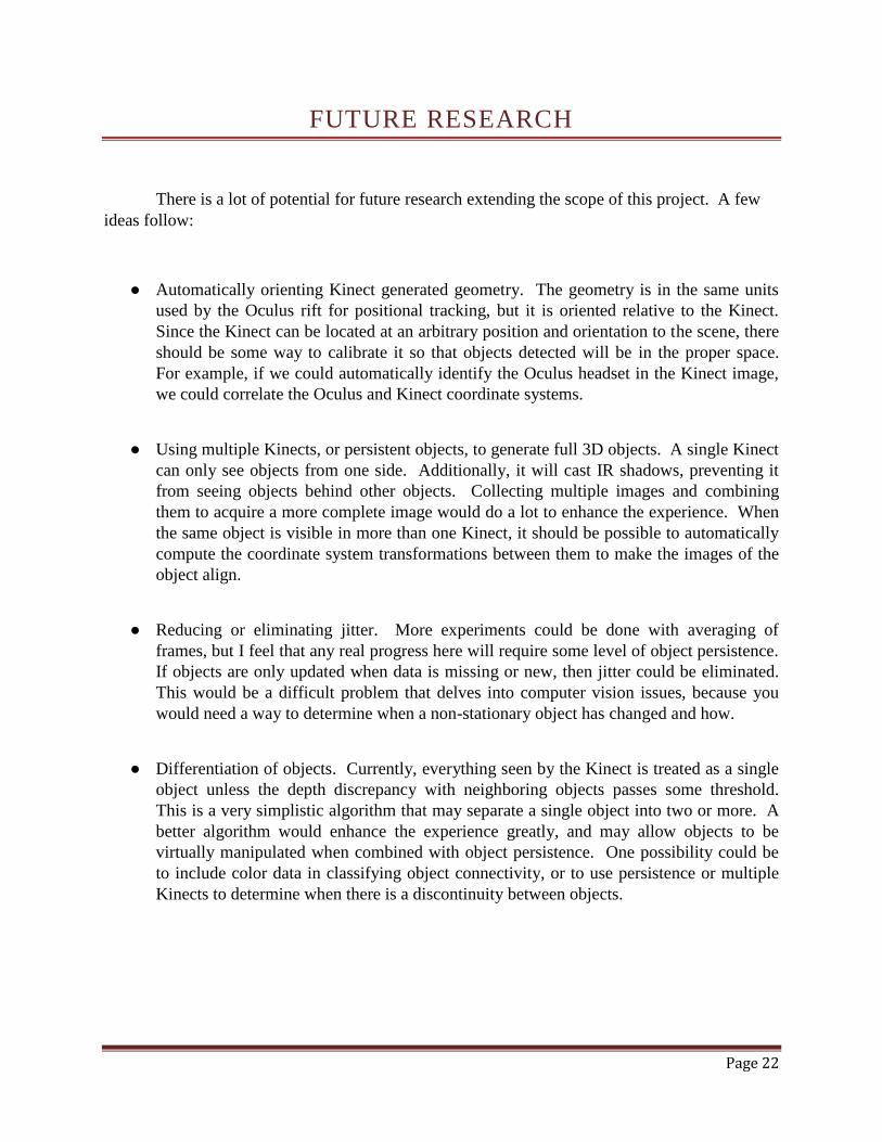
FUTURE RESEARCH
There is a lot of potential for future research extending the scope of this project. A few
ideas follow:
● Automatically orienting Kinect generated geometry. The geometry is in the same units
used by the Oculus rift for positional tracking, but it is oriented relative to the Kinect.
Since the Kinect can be located at an arbitrary position and orientation to the scene, there
should be some way to calibrate it so that objects detected will be in the proper space.
For example, if we could automatically identify the Oculus headset in the Kinect image,
we could correlate the Oculus and Kinect coordinate systems.
● Using multiple Kinects, or persistent objects, to generate full 3D objects. A single Kinect
can only see objects from one side. Additionally, it will cast IR shadows, preventing it
from seeing objects behind other objects. Collecting multiple images and combining
them to acquire a more complete image would do a lot to enhance the experience. When
the same object is visible in more than one Kinect, it should be possible to automatically
compute the coordinate system transformations between them to make the images of the
object align.
● Reducing or eliminating jitter. More experiments could be done with averaging of
frames, but I feel that any real progress here will require some level of object persistence.
If objects are only updated when data is missing or new, then jitter could be eliminated.
This would be a difficult problem that delves into computer vision issues, because you
would need a way to determine when a non-stationary object has changed and how.
● Differentiation of objects. Currently, everything seen by the Kinect is treated as a single
object unless the depth discrepancy with neighboring objects passes some threshold.
This is a very simplistic algorithm that may separate a single object into two or more. A
better algorithm would enhance the experience greatly, and may allow objects to be
virtually manipulated when combined with object persistence. One possibility could be
to include color data in classifying object connectivity, or to use persistence or multiple
Kinects to determine when there is a discontinuity between objects.

Page 23
REFERENCES
(Brigley, no date) Brigley, Greg. “Take Control of Your Operating Room." GestSure. No date.
Web. 8 Apr. 2015.
(Carnegie Mellon, 2001) Carnegie Mellon. “Carnegie Mellon Goes to the Super Bowl."
Carnegie Mellon Goes to the Super Bowl. Jan. 2001. Web. 8 Apr. 2015.
(Freedman, 2012) Freedman, Barak, et al. “Depth Mapping Using Projected Patterns.” Prime
Sense Ltd., assignee. Patent US 8150142 B2. 3 Apr. 2012. Print.
(Goza, 2004) Goza, S.M., et al. “Telepresence Control of the NASA/DARPA Robonaut on a
Mobility Platform.” CHI ‘04 Proceedings of the SIGCHI Conference on Human Factors
in Computing Systems, pp. 623-629. ACM. 25 Apr. 2004. Print.
(Hine, 1994) Hine, B. P., et al. "The Application of Telepresence and Virtual Reality to Subsea
Exploration." Proc. ROV '94. The 2nd Workshop on Mobile Robots for Subsea
Environments, May 1994. Print.
(Hine, 1995) Hine, B., et al. "VEVI: A Virtual Environment Teleoperations Interface for
Planetary Exploration." SAE 25th International Conference on Environmental Systems,
July 1995. Print.
(Izadi, 2011) Izadi, Shahram, et al. "KinectFusion: Real-time 3D Reconstruction and Interaction
Using a Moving Depth Camera." Microsoft Research. ACM Symposium on User
Interface Software and Technology, Oct. 2011. Web. 8 Apr. 2015.
(Kanade, 1995) Kanade, Takeo, Peter Rander, and P. J. Narayanan. "Virtualized Reality:
Concepts and Early Results." IEEE Workshop on the Representation of Virtual Scenes,
pp. 69-76. IEEE. 24 June 1995. Print.

Page 24
(Kanade, 1997) Kanade, Takeo, Peter Rander, and P. J. Narayanan. "Virtualized Reality:
Constructing Virtual Worlds from Real Scenes." IEEE Multimedia, Immersive
Telepresence Vol. 4, Iss. 1, pp. 34-47. IEEE. Jan. 1997. Print.
(Microsoft, 2013) Microsoft. “Kinect Sign Language Translator Expands Communication
Possibilities." Microsoft Research. 30 Oct. 2013. Web. 8 Apr. 2015.
(OpenKinect, 2013) OpenKinect Project. "Imaging Information." OpenKinect. 12 Nov. 2013.
Web. 17 Apr. 2015.
(Ota, no date) Ota, Jonathan. "Virtualized Reality." Virtualized Reality - Jonathan Ota. No date.
Web. 8 Apr. 2015.
(Terndrup, 2015) Terndrup, Matthew. "Reverse Engineering the Oculus Rift DK2 Provides
Brilliant Insight into Inner Workings." Road to VR. 8 Oct. 2014. Web. 8 Apr. 2015.
(Thin, 2012) Thin, Alasdair G. "A Game-Based Virtualized Reality Approach for Simultaneous
Rehabilitation of Motor Skill and Confidence." Advances in Human-Computer
Interaction Vol. 2012. Hindawi Publishing Corporation. 8 Oct. 2012. Web. 8 Apr. 2015.