Embed Size (px)
DESCRIPTION
FYP
Citation preview
1
Vehicle Structure Design & Material Selection
MEC 4630
Project#7: Buckling of Composite Plates With Cutouts
Semester II, 2012/2013
Lecturer: Dr Meftah Hrairi
Group Members:
Muhammad ‘Atif B. Ali 1021631
Nabeel Yahia Emran 0827755
Heitem Abdelrezak Hashim Hilal 0817203

2
Table of Content
Title Page
Abstract 3
Introduction 3
Literature Review 5
Results/Simulations 9-14
Discussion 15
Conclusion, Recommendation, Improvements 17
References 18

3
ABSTRACT
This project was prepared and accomplished in order to fulfill a part of the assessment for the Course Vehicle
Structural Design and Materials Selection. The work done was as an attempt to investigate the effect of different
Aspect Ratios, Cutout Shapes and Boundary Conditions for a thin composite plate. A finite element analysis has been
run using ANSYS GUI of Version 14.5. The set of specifications have been through detailed methodology. The
parametric study was performed and observations on results along with the related plots were presented with
respect critical stress based on different cases and analysis criteria. Recommendations and possible improvements
were also discussed.
1. INTRODUCTION
COMPOSITE MATERIALS
A composite material consists of two or more constituent materials combined in such a way that the resulting
material has more useful applications than the constituent materials alone. The constituent materials play a key role
in the development of the final material properties. Advanced composite materials used in structural applications
are obtained by reinforcing a matrix material with continuous fibers having high strength and stiffness properties.
The selection of a composite material for any application will involve selection of reinforcing fiber and matrix, and
their fractional volume in the resulting material. A properly selected combination will give a composite material with
following advantages:
• High strength and stiffness-to-weight ratio;
• Low weight;
• Excellent corrosion resistance;
• Excellent fatigue resistance ;
• Can be “tailored to fit”.
Today, composite laminates have many applications as advanced engineering materials, primarily as components in
aircrafts, power plants, civil engineering structures, ships, cars, rail vehicles, robots, prosthetic devices, sports
equipment etc. The major advantage of composite material is ability of the controllability fiber alignment. By
arranging layers and fiber direction, laminated material with required strength and stiffness properties to specific
design conditions, can possibly be achieved [1]. The elastic and mechanical properties of composite material are not
set until the final structure is manufactured. These properties could be obtained by means of standardized tests or
with numerical methods [1, 2]. Because of the expenses and inconveniences in testing, it is more popular to make a
numerical estimate of these properties.

4
In a laminate plate individual continuous fiber/matrix laminas are oriented in the required directions and bonded
together. In paper, by using terms of the plane classical lamination theory and the stress-strain relationships [1, 3],
the numerical arrangement of the stress and strain values for the angle-ply symmetric laminated plates for various
lamination angles is carried out.
IMPORTANT TERMS
Laminate- A laminate is a built-up of a stack of laminae having fibers orientated in different directions. A lay-up of
typical laminate is shown in Figure 3. A laminate having plies placed symmetrically about the centerline is termed as
symmetric laminate as shown in Figure 3.
Prepreg, Pre-impregnated- A combination of mat, fabric, fibers with resin, advanced to B-stage, ready for curing.
Figure 3- Typical Laminate Lay-up
(02/±45/0/90/0/±45/02) or (02/±45/0/90)S
5
LITERATURE REVIEW
Buckling of flat plates may be experienced when the plate is excessively stressed in compression along opposite
edges, or in shear uniformly distributed around all edges of the plate, or a combination of both. This necessities
establishment of values for the critical buckling stress in compression σcr and in shear τcr .
From the experiment, it was found that the ±45° Notched Glass Fiber Plate with the Half Rhombus Cut-out can carry a higher
load before the fracture load of (2.11KN) as compared to the other types of the notched plates and the ±45° Glass Fiber
Laminated Plate with a Circular Hole Cut-out can carry a higher load before the fracture load of (1.82kN) as compared to the
other types of the central cut-out plates. It has also been found that the ±45° glass fiber laminated plate without any cut-out
records the highest fracture load value compared to the plates with the cut-out. Figures 6 and Figure 7 show the fracture load of
the ±45° glass fiber laminated plate.
In many engineering structures such as columns, beams, or plates, their failure develops not only from excessive
stresses but also from buckling. Buckling behaviour significantly changes with change in aspect ratio, d/b ratio, d/D
ratio. Plate seems to work as a column of finite width at higher aspect ratio. If we decrease aspect ratio, there is also
a limit below which failure does not take place by elastic buckling.
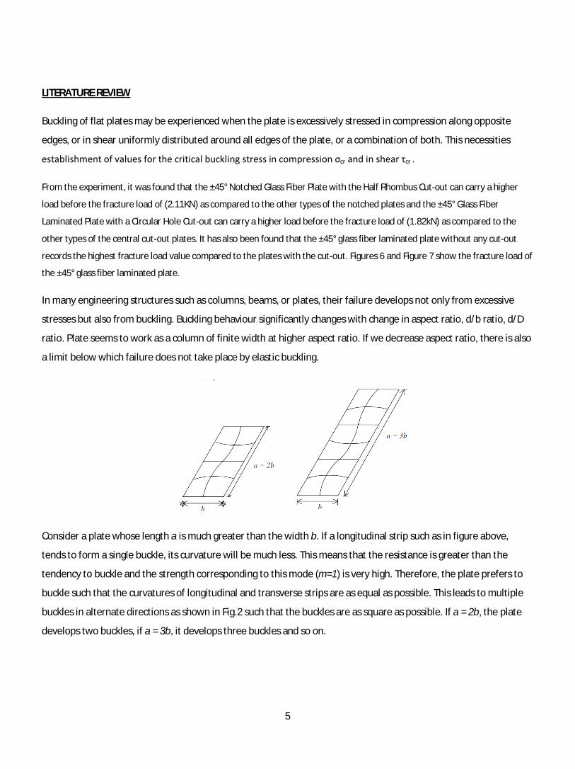
Consider a plate whose length a is much greater than the width b. If a longitudinal strip such as in figure above,
tends to form a single buckle, its curvature will be much less. This means that the resistance is greater than the
tendency to buckle and the strength corresponding to this mode (m=1) is very high. Therefore, the plate prefers to
buckle such that the curvatures of longitudinal and transverse strips are as equal as possible. This leads to multiple
buckles in alternate directions as shown in Fig.2 such that the buckles are as square as possible. If a = 2b, the plate
develops two buckles, if a = 3b, it develops three buckles and so on.

6
2. PROBLEM STATEMENT
Creating and running a finite element (FE) analysis, using ANSYS, to perform the parametric study of the bucking of
the specified composite thin plate as described below: Length = 200mm, Width = 100 mm, Thickness of laminate =
0.125 mm No. of layup = 16, Arrangement of layup [± 40/90/0]2s E11 = 128x103 N/mm2, E22 = 11x103 N/mm2, G12
= 4.48 x10³ N/mm2 G13 = G23 = 1.53 x10³ N/mm2, ν = 0.25.
OBJECTIVES
1. To Build an FE model for a thin composite plate with a cutout and to the buckling analysis.
2. To Study the effects of various cutout shape, aspect ratio (L/W), and boundary conditions (SSSS, CSSS, CCSS,
CCCC) on buckling strength of the rectangular thin composite plate.
3. To prepare of summary for observations on the results based on critical loads in all cases and with sample
plots of the buckled plates.
4. To Critically appraise the results derived from the FE analysis in light of the literature review.
5. To comprehensively study the fundamentals of composite plate structures and its engineering importance
and applications
6. To comprehensively study the capabilities of ANSYS and getting to master its essential techniques and
methods of analysis.
7. To run the buckling analysis using different methods and to omit testing for rhombus cutout shape since it
gives almost the same effect as the case of square cutout shape.
8. To further study the severe effect of circular cutout shape case and SSSS boundary condition.

7
Finite Element Analysis
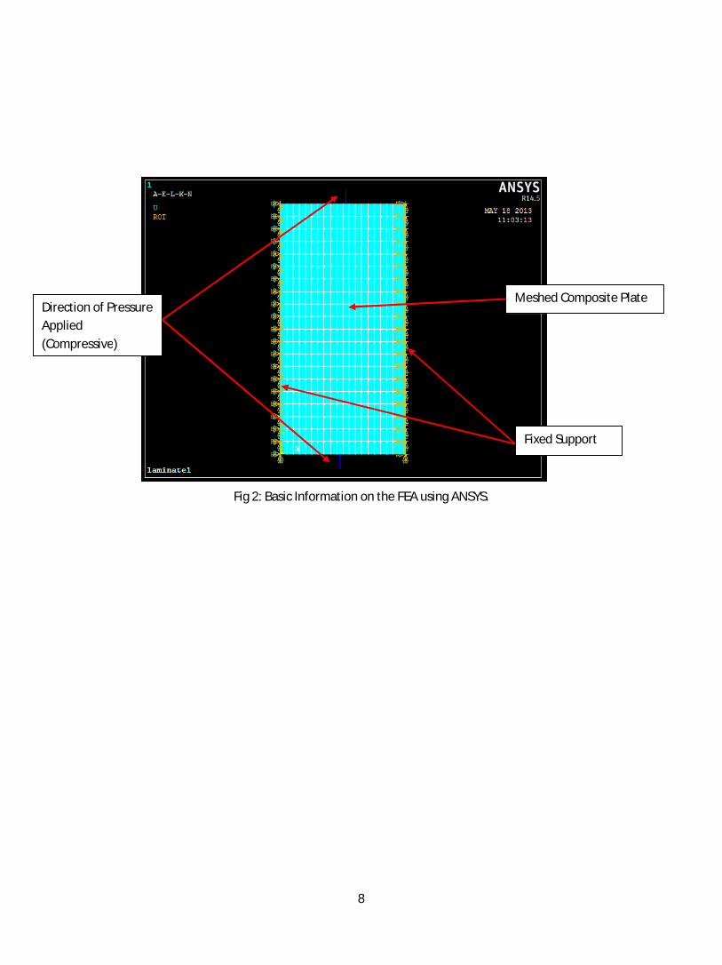
Methodology of Finite Element Analysis (FEA) Using ANSYS
1) MODELLING: It includes defining element type, real constants, material properties and modelling. In this
study, 4 noded linear layer Shell 181 was selected as the element type.
Element’s Parametric:
- Length = 200mm, Width = 100 mm, Thickness of laminate = 0.125 mm
- No. of layup = 16, Arrangement of layup [± 40/90/0]2s
- E11 = 128x103 N/mm2, E22 = 11x103 N/mm2, G12 = 4.48 x10³ N/mm2 G13 = G23 = 1.53 x10³ N/mm2, ν = 0.25
2) SOLUTION (STATIC ANALYSIS): It includes applying boundary conditions, applying loads and solving the static
analysis. For analysis on different aspect ratio and different cut out shape, fixed-fixed boundary condition
was applied. But for analysis on boundary condition, the type of boundaries were varied. The load imposed
is 100N/mm2 for all cases.
3) POSTPROCESSOR: This step includes listing buckling loads and viewing buckled shapes.
Fig 1: Lay up of laminate
8
Fig 2: Basic Information on the FEA using ANSYS.
Fixed Support
Direction of Pressure Applied (Compressive)
Meshed Composite Plate
9
3. RESULTS FORM FINITE ELEMENT ANALYSIS USING ANSYS
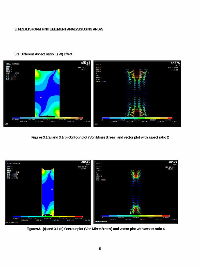
3.1 Different Aspect Ratio (L/W) Effect.
Figures 3.1(a) and 3.1(b) Contour plot (Von Mises Stress ) and vector plot with aspect ratio 2
Figures 3.1(c) and 3.1 (d) Contour plot (Von Mises Stress ) and vector plot with aspect ratio 4

10
Figures 3.1 (e) and 3.1 (f) Contour plot (Von Mises Stress ) and vector plot with aspect ratio 8
11
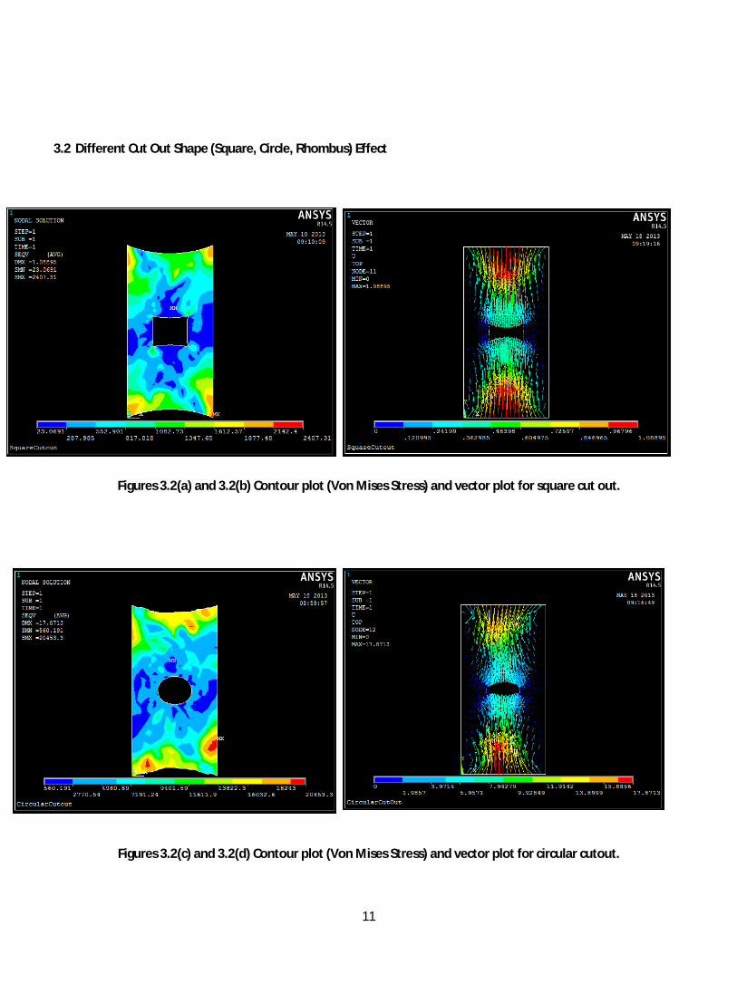
3.2 Different Cut Out Shape (Square, Circle, Rhombus) Effect
Figures 3.2(a) and 3.2(b) Contour plot (Von Mises Stress) and vector plot for square cut out.
Figures 3.2(c) and 3.2(d) Contour plot (Von Mises Stress) and vector plot for circular cutout.
12
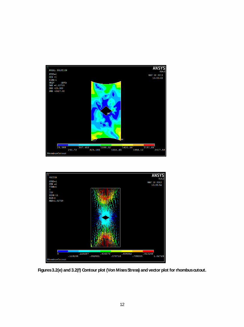
Figures 3.2(e) and 3.2(f) Contour plot (Von Mises Stress) and vector plot for rhombus cutout.
13
3.3 Different Boundary conditions effects:
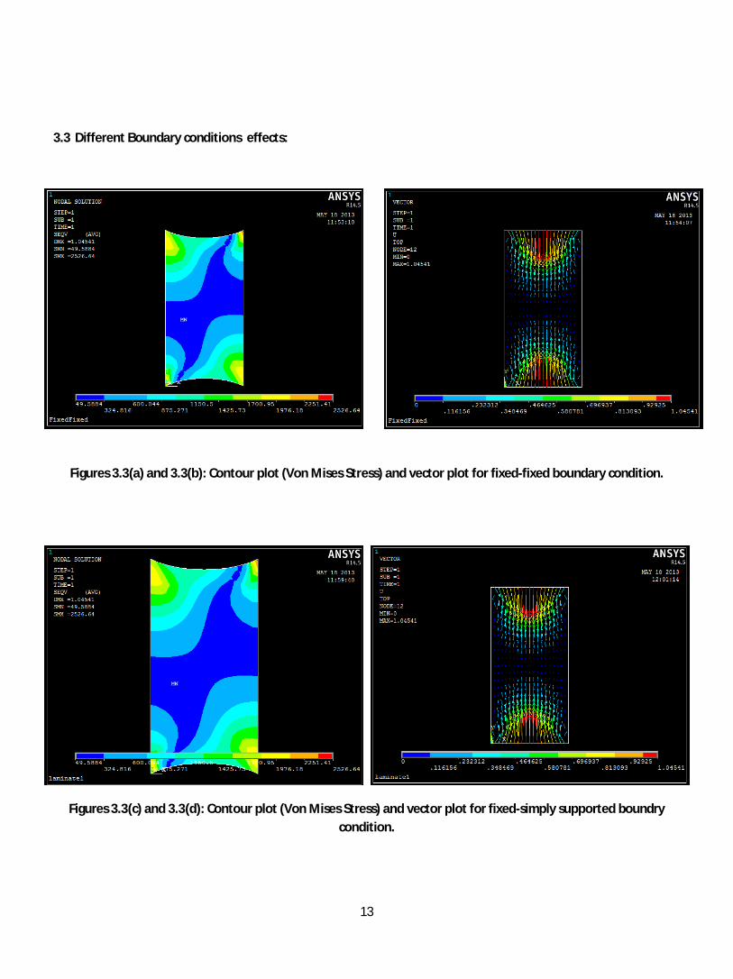
Figures 3.3(a) and 3.3(b): Contour plot (Von Mises Stress) and vector plot for fixed-fixed boundary condition.
Figures 3.3(c) and 3.3(d): Contour plot (Von Mises Stress) and vector plot for fixed-simply supported boundry condition.

14
\
Figures 3.3(e) and 3.3(f): Contour plot (Von Mises Stress) and vector plot for simply supported-simply supported boundry condition.
15
DISCUSSION
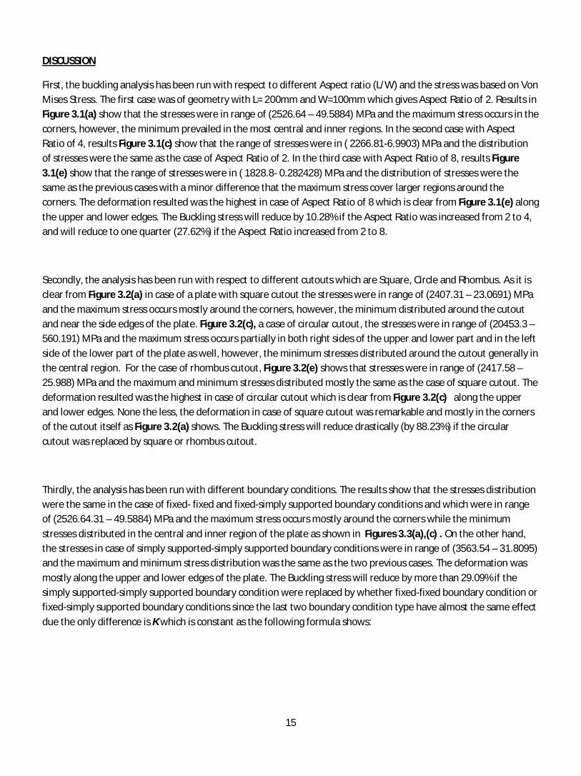
First, the buckling analysis has been run with respect to different Aspect ratio (L/W) and the stress was based on Von Mises Stress. The first case was of geometry with L= 200mm and W=100mm which gives Aspect Ratio of 2. Results in Figure 3.1(a) show that the stresses were in range of (2526.64 – 49.5884) MPa and the maximum stress occurs in the corners, however, the minimum prevailed in the most central and inner regions. In the second case with Aspect Ratio of 4, results Figure 3.1(c) show that the range of stresses were in ( 2266.81-6.9903) MPa and the distribution of stresses were the same as the case of Aspect Ratio of 2. In the third case with Aspect Ratio of 8, results Figure 3.1(e) show that the range of stresses were in ( 1828.8- 0.282428) MPa and the distribution of stresses were the same as the previous cases with a minor difference that the maximum stress cover larger regions around the corners. The deformation resulted was the highest in case of Aspect Ratio of 8 which is clear from Figure 3.1(e) along the upper and lower edges. The Buckling stress will reduce by 10.28% if the Aspect Ratio was increased from 2 to 4, and will reduce to one quarter (27.62%) if the Aspect Ratio increased from 2 to 8.
Secondly, the analysis has been run with respect to different cutouts which are Square, Circle and Rhombus. As it is clear from Figure 3.2(a) in case of a plate with square cutout the stresses were in range of (2407.31 – 23.0691) MPa and the maximum stress occurs mostly around the corners, however, the minimum distributed around the cutout and near the side edges of the plate. Figure 3.2(c), a case of circular cutout, the stresses were in range of (20453.3 – 560.191) MPa and the maximum stress occurs partially in both right sides of the upper and lower part and in the left side of the lower part of the plate as well, however, the minimum stresses distributed around the cutout generally in the central region. For the case of rhombus cutout, Figure 3.2(e) shows that stresses were in range of (2417.58 – 25.988) MPa and the maximum and minimum stresses distributed mostly the same as the case of square cutout. The deformation resulted was the highest in case of circular cutout which is clear from Figure 3.2(c) along the upper and lower edges. None the less, the deformation in case of square cutout was remarkable and mostly in the corners of the cutout itself as Figure 3.2(a) shows. The Buckling stress will reduce drastically (by 88.23%) if the circular cutout was replaced by square or rhombus cutout.
Thirdly, the analysis has been run with different boundary conditions. The results show that the stresses distribution were the same in the case of fixed- fixed and fixed-simply supported boundary conditions and which were in range of (2526.64.31 – 49.5884) MPa and the maximum stress occurs mostly around the corners while the minimum stresses distributed in the central and inner region of the plate as shown in Figures 3.3(a),(c) . On the other hand, the stresses in case of simply supported-simply supported boundary conditions were in range of (3563.54 – 31.8095) and the maximum and minimum stress distribution was the same as the two previous cases. The deformation was mostly along the upper and lower edges of the plate. The Buckling stress will reduce by more than 29.09% if the simply supported-simply supported boundary condition were replaced by whether fixed-fixed boundary condition or fixed-simply supported boundary conditions since the last two boundary condition type have almost the same effect due the only difference is K which is constant as the following formula shows:

16
Where; E : modulus of elasticity t : thickness of plate b : width of plate a : length of plate ν : Poisson's ratio k : constant; depends upon plate
shape b/a and support of sides.
Results Summary:
Analysis criteria
Aspect Ratio(L/W)
Cutout Shape
Boundary Conditions
Maximum
Stress (Critical)
2526.64 MPa
In case of (L/W) = 2
20453.3 MPa
In case of circular cutout
3563.54 MPa
In case of SSSS

17
RECOMMENDATIONS
1. To comprehensively study the capabilities of ANSYS and getting to master its essential techniques and
methods of analysis.
2. To run the buckling analysis using different methods and to omit testing for rhombus cutout shape since it
gives almost the same effect as the case of square cutout shape.
3. To further study the severe effect of circular cutout shape case and SSSS boundary condition.
IMPROVEMENTS
Improvements for the analysis could be made possible if different element types were employed. Results of each element type are to be compared so the outcomes then could be optimized. Shell 99 composite element could also be used to get a better result. SHELL99 may be used for layered applications of a structural shell model. While SHELL99 does not have some of the nonlinear capabilities of SHELL91, it usually has a smaller element formulation time. SHELL99 allows up to 250 layers. Also, employing ANSYS Workbench makes the creation of the model relatively easier.
In addition, different analysis type such as Eigen Buckling might give a better results. Eigenvalue analysis predicts the theoretical buckling strength of a structure which is idealized as elastic. For a basic structural configuration, structural eigenvalues are computed from constraints and loading conditions.
Improvements on the design of the thin composite plates could be optimized if the cutout were of sharp edges with lower aspect ratio and CSSS boundary conditions.
It is very difficult to get the literature review for composite buckling that involve the same mechanical properties, therefore an experiment should be conducted in order to obtain experimental for comparison purpose.
CONCLUSION
To sum up, the different tasks have been met. The plots and the summary of results showed the effect of circular
cutout, higher aspect ratio and SSSS boundary conditions were associated with the most critical stress, especially the
case of circular cutout as the critical stress increased by more than 88 % of cases square and rhombus. The
difficulties rose from the lack of composite structures but it were overcome through the good understanding gained
from reviewing the literature. Hence, the project would be considered a contributing attempt in understanding the
behavior of buckling loads, under different effects, on thin composite plates with cutouts.
18
References:
*Please refer to the documents in the reference folder, inside the CD. Among te reference are:-
1. INTRODUCTION TO PLATE BUCKLING
2. Effect of Buckling on Glass Fiber/Epoxy Plate 1Basharia A.A. Yousef, Mohamed H. Elsheikh, Mohd F. M. Sabri, Hakim S. S. Aljibori, Suhana M. Said 1Department of Mechanical Engineering, College of Engineering and Architecture, University of Bahri P. o. Box 13104, Khartoum, Sudan 2Department of Mechanical Engineering, Faculty of Engineering, University of Malaya, 50603 Kuala Lumpur, Malaysia
3. ANSYS, Picking an Element Type For Structural Analysis: by Paul Dufour
4. LINEAR BUCKLING ANALYSIS OF LAMINATED COMPOSITE PLATE Nagendra Singh Gaira1, Nagendra Kumar Maurya2,Rakesh Kumar Yadav3 1M.Tech student,AFSET,Faridabad, [email protected] 2 ME Deptt. G.L.Bajaj Institute of Technology & Management, Greater Noida,UP,India 3 ME Deptt. Al Falah School of Engineering & Technology, Faridabad

19