Embed Size (px)
Citation preview

R E P O R T
Marathon Solar
Visual Impact Assessment
San Bernardino County, California
Lucerne Valley
June 14, 2012
4225 Executive Square, Suite 1600 La Jolla, CA 92037 858.812.9292 Fax: 858.812.9293

TABLE OF CONTENTS
i
Section 1 Project Overview .............................................................................................1-1
1.1 Project Description ................................................................................................ 1-1
Section 2 Project Setting ................................................................................................2-1
2.1 Regulatory Setting ................................................................................................. 2-1 2.1.1 Federal Requirements ............................................................................... 2-1 2.1.2 State Requirements ................................................................................... 2-2 2.1.3 Regional and Local Requirements ............................................................. 2-3
Section 3 Assessment Methodology ..............................................................................3-1
3.1 Study Area ............................................................................................................. 3-1 3.2 Key Observation Points ......................................................................................... 3-1 3.3 Existing Conditions ............................................................................................... 3-1 3.4 Visual Simulations ................................................................................................. 3-6 3.5 Impact Analysis ..................................................................................................... 3-6
3.5.1 Visual Contrast Rating .............................................................................. 3-6 3.5.2 Determination of Significance .................................................................. 3-7
Section 4 Affected Environment .....................................................................................4-1
4.1 Regional and Site setting ....................................................................................... 4-1 4.2 Project-level Conditions ........................................................................................ 4-4
4.2.1 Key Observation Point 1 ........................................................................... 4-4 4.2.2 Key Observation Point 2 ........................................................................... 4-6
Section 5 Environmental Consequences .......................................................................5-1
5.1 Construction-related Impacts ................................................................................. 5-1 5.2 Operational Impacts ............................................................................................... 5-1
5.2.1 KOP 1 ........................................................................................................ 5-1 5.2.2 KOP 2 ........................................................................................................ 5-4 5.2.3 Lighting and Glare .................................................................................... 5-4
5.3 Cumulative Impacts ............................................................................................... 5-5 5.3.1 KOP 1 - Cumulative Impacts .................................................................... 5-5 5.3.2 KOP 2 - Cumulative Impacts .................................................................... 5-5
Section 6 Impact Significance ........................................................................................6-1
Section 7 References ......................................................................................................7-1
Section 8 Preparers .........................................................................................................8-1

List of Figures and Appendices
ii
Figures
Figure 1 – Project Vicinity and Regional Overview ........................................................................... 1-3
Figure 2 – Population Density Map .................................................................................................... 3-2
Figure 3 – Viewshed Analysis ............................................................................................................ 3-3
Figure 4 – Key Observation Points ..................................................................................................... 3-4
Figure 5 – Character Photo 1 .............................................................................................................. 4-2
Figure 6 – Character Photo 2 .............................................................................................................. 4-2
Figure 7 – Character Photo 3 .............................................................................................................. 4-3
Figure 8 – Character Photo 4 .............................................................................................................. 4-3
Figure 9 – KOP 1 Existing Conditions ............................................................................................... 4-5
Figure 10 – KOP 2 Existing Conditions ............................................................................................. 4-7
Figure 11 – KOP 1 Proposed Conditions ............................................................................................ 5-3
Figure 12 – KOP 2 Proposed Conditions ............................................................................................ 5-4
Figure 13 – Cumulative Viewshed Analysis ....................................................................................... 5-6
Figure 14 – KOP 1 Proposed Cumulative Conditions ........................................................................ 5-7
Figure 15 – KOP 2 Proposed Cumulative Conditions ........................................................................ 5-8
Appendices
Appendix A Contrast Rating Forms

List of Acronyms and Abbreviations
iii
3D three-dimensional
AC alternating current
ADT Average Daily Trips
ASL Above Sea Level
BLM Bureau of Land Management
CADD Computer-aided drafting and design
CEQA California Environmental Quality Act
CUP Conditional Use Permit
FHWA Federal Highway Administration
GIS geographic information systems
KOPs Key Observation Points
kv kilovolt
MW megawatt
OHV Off Highway Vehicle
Project Marathon Solar Project
PV photovoltaic
SCE Southern California Edison
USFS United States Forest Service
VIA Visual Impact Analysis

SECTIONONE Project Overview
1-1
SECTION 1 PROJECT OVERVIEW
Marathon Solar, LLC proposes to construct a photovoltaic (PV) electric generating facility in the Lucerne
Valley Community Planning area of San Bernardino County (Figure 1). The proposed site is currently
zoned LV/AG and under County Code Chapter 82.04, electrical power generation is allowed in this zone
by Conditional Use Permit (CUP). This Visual Impact Assessment (VIA) is prepared in support of the
Marathon Solar CUP Application, Project Number P201200012.
The Marathon Solar Project (Project) would be located in close proximity to the proposed Agincourt
Solar Project, a similar PV electric generating facility that is also under review by CUP application. On
February 8, 2012 the San Bernardino County Land Use Services Department issued a letter requesting
“Additional Reports” be prepared to support the permitting and review process of the Marathon Solar
CUP application. This included preparing a, “[VIA] addressing views from State Route 18; and views
from the trails on the northern slope of Blackhawk Mountain (including cumulative impacts).” This VIA
is prepared in response to the County’s request. This VIA provides a visual impact analysis of the
Marathon Solar project alone, as well as the potential cumulative visual impact associated with
construction of both the Marathon and Agincourt Solar Projects. A separate VIA is prepared addressing
the potential impacts associated with construction of the Agincourt Project.
1.1 PROJECT DESCRIPTION
The Project consists of a 20 megawatt (MW) alternating current (AC) photovoltaic (PV) solar electric
generating facility and would occupy approximately 130 acres of a 152-acre site. The Project would
connect with a new Southern California Edison (SCE) 33-kilovolt (kV) distribution line located along
Camp Rock Road. No new offsite transmission line is proposed. The electricity produced by the Project
will be marketed to power buyers through a long-term power purchase agreement.
The proposed solar power generation facility would be comprised of the following major components:
non-reflective PV solar module arrays mounted on fixed-tilt or single-axis trackers and a racking system
supported by embedded piers. The site would also include approximately 20 inverters on small concrete
pads, a switching station in an enclosure measuring approximately 200 by 200 feet in plan view, an
unmanned communications enclosure measuring approximately 20 by 30 feet in plan view, two Conex
boxes for equipment storage, and buried collector lines. Concrete pads would be sized and installed to
accommodate their associated equipment (inverters and switchgear). The top-of-concrete elevation is to
be 6 inches above-grade-level locally to maintain flow away from the foundation.
No off-site improvements are anticipated with the exception of the development of site access points.
Typical site access will be 25 feet wide, accommodating 75-foot turning radii in both directions. The
proposed site access will include a 75-foot-long drive apron and a roadway section paved with asphalt.
Internal site circulation would include a 25-foot-wide perimeter road of gravel. Maintenance roads with
access to the solar panels would be improved (minimally graded, dirt or gravel) to provide truck access.
Upon completion of the proposed Project, vegetation or dust palliatives or other best management
practices may be used to control wind and water erosion during operations.

SECTIONONE Project Overview
1-2
The solar facility would be unmanned. A six foot high chain link security fence topped by a one foot
section of barbed wire will be installed at the property setback. Several part-time employees would visit
the site periodically (e.g., monthly or bi-monthly) and several times a year the employees or a contractor
would visit the site to wash the PV panels.
The Project’s lighting system will provide operation and maintenance personnel with illumination for
both normal and emergency conditions. Lighting will be designed to provide the minimum illumination
needed to achieve safety and security objectives. Lighting will be directed downward and shielded to
focus illumination on the desired areas only to avoid light spillage on adjacent properties. Project lighting
will be located at each inverter station and switchyard. Lighting will be no brighter than required to meet
safety and security requirements, and the lamp fixtures and lumens will be selected accordingly. All
project lighting will be switched and without timers.
The study area for visual resources included all areas located within a five-mile radius of the proposed
Project Site.

?åE
SOURCES: USGS Quads: Cougar Buttes, 1978; Lucerne Valley, 1978. Project Sites (BSE, 2012),Aerial (Bing Maps, 2012)
PROJECT VICINITY AND REGIONAL OVERVIEW
MARATHON
SAN BERNARDINO COUNTY, CA
CREATED BY: DT
PM: BM PROJ. NO: 28907132.23000
FIG. NO:
1SCALE: 1" = 2500' (1:24,000)
1000 0 1000 2000 Feet
O
SCALE CORRECT WHEN PRINTED AT 8.5X11Pa
th:
G:\
gis
\pro
ject
s\1
57
7\2
89
07
13
2\m
ap
_d
ocs
\mxd
\MA
RA
TH
ON
_L
oca
tio
n_
Ma
p.m
xd,
da
vid
_tr
zeci
ak,
6/1
2/2
01
2,
4:3
4:1
5 P
M
DATE: 6/12/2012
Marathon, 0449-172-75, 0449-631-02
Project Location
Regional Overview

SECTIONTWO Project Setting
2-1
SECTION 2 PROJECT SETTING
The following subsections describe the regulatory requirements associated with the proposed Project and
the physical setting in which the project is located.
2.1 REGULATORY SETTING
This section provides an overview of the pertinent federal, state, and local policies governing aesthetics.
The California Environmental Quality Act (CEQA) standards for review of visual and aesthetic resources
were used to assess the potential impacts of the proposed project. Additionally, local policies governing
aesthetics, such as the San Bernardino County General Plan, and Lucerne Valley Specific Plan are also
reviewed.
2.1.1 Federal Requirements
The federal regulations and other requirements that apply to the proposed Project are summarized below.
2.1.1.1 National Scenic Byways
The National Scenic Byways Program is under the jurisdiction of the Federal Highway Administration
(FHWA). The program is a grass-roots collaborative effort established to help recognize, preserve and
enhance selected roads throughout the U.S. Since 1992, the National Scenic Byways Program has funded
3,049 projects for state and nationally designated byway routes in 50 states, Puerto Rico and the District
of Columbia. The U.S. Secretary of Transportation recognizes certain roads as All-American Roads or
National Scenic Byways based on one or more archeological, cultural, historic, natural, recreational and
scenic qualities.
According to information provided on the National Scenic Byways website (http://byways.org/), which
lists scenic byways by state, no designated scenic byways are located in the vicinity of the proposed
Project site.
2.1.1.2 National Trails
The National Trails System [12 U.S. Code Section 1242] allows federal designation of those extended
trails (over 100 miles in length) that provide for the maximum outdoor recreation potential and for the
conservation and enjoyment of the significant scenic, historic, natural, or cultural qualities of the areas
through which they pass. The intent of establishing the code is to protect the trail corridors associated
with national scenic trails and the high-priority potential sites and segments of national historic trails to
the degrees necessary to ensure that the values for which each trail was established remain intact.
According to information provided on the National Park Service website (http://www.nps.gov/nts/), no
national scenic trails are located in the vicinity of the proposed Project site.

SECTIONTWO Project Setting
2-2
2.1.1.3 Federal Wild and Scenic Rivers
According to the Wild and Scenic Rivers Act (16 U.S. Code 1271 et seq.), it is the policy of the U.S. that
certain selected rivers of the nation which, with their immediate environments, possess outstandingly
remarkable scenic, recreational, geologic, fish and wildlife, historic, cultural, or other similar values, shall
be preserved in free-flowing condition, and that they and their immediate environments shall be protected
for the benefit and enjoyment of present and future generations. The Congress declared that the
established national policy of dam and other construction at appropriate sections of the rivers of the U.S.
must be complemented by a policy that would preserve other selected rivers or sections thereof in their
free-flowing condition to protect the water quality of such rivers and to fulfill other vital national
conservation purposes.
According to information provided on the National Wild and Scenic Rivers website
(http://www.rivers.gov/wildriverslist.html), no designated wild and scenic rivers are located in the
vicinity of the proposed Project site.
2.1.2 State Requirements
The state regulations and other requirements that apply to the proposed Project are summarized below.
2.1.2.1 California Environmental Quality Act
CEQA requires that the state to take all action necessary to provide the people of the state
“with…enjoyment of aesthetic, natural, scenic and historic environmental qualities” [California Public
Resources Code Section 21001(b)].
2.1.2.2 State Scenic Highway Program
Scenic corridor protection programs include policies intended to preserve the scenic qualities of the
highway corridor, including regulation of land use and density of development, detailed land and site
planning, control of outdoor advertising (including a ban on billboards), careful attention to and control of
earthmoving and landscaping, and careful attention to design and appearance of structures and equipment
(California Streets and Highways Code Section 260 et seq.).
According to the California Scenic Highway Mapping System website,
(http://www.dot.ca.gov/hq/LandArch/scenic_highways/index.htm), the County of San Bernardino
contains two highways designated by Caltrans as “eligible” but not officially designated scenic
highways1: State Route 18 (SR-18) and State Route 247 (SR-247). Additional information regarding these
roadways is provided in Section 2.1.3.1.
1 The State Scenic Highway System includes a list of highways that are either eligible for designation as scenic highways or have
been so designated. These highways are identified in Section 263 of the Streets and Highways Code. The status of a state scenic
highway changes from eligible to officially designated when the local jurisdiction adopts a scenic corridor protection program,
applies to the California Department of Transportation for scenic highway approval, and receives notification from Caltrans that
the highway has been designated as a Scenic Highway.

SECTIONTWO Project Setting
2-3
2.1.3 Regional and Local Requirements
The following regional and local regulations and other requirements that apply to the proposed project are
summarized below.
2.1.3.1 County of San Bernardino General Plan
The County of San Bernardino General Plan (General Plan) text was adopted by the Board of Supervisors
on March 13, 2007. It became effective on April 12, 2007 and most recently amended as of December 6,
2011. The General Plan is the fundamental policy document for the unincorporated, privately owned
lands of San Bernardino County.
Scenic resources are discussed in the Open Space Element of the General Plan (County of San Bernardino
2007a). The General Plan policies discussed below are applicable to scenic resources in the County.
Policy OS 5.1: Features meeting the criteria identified below will be considered for designation as scenic
resources.
a. A roadway, vista point, or area that provides a vista of undisturbed natural areas.
b. Includes a unique or unusual feature that comprises an important or dominant portion of the
viewshed (the area within the field of view of the observer).
c. Offers a distant vista that provides relief from less attractive views of nearby features (such as
views of mountain backdrops from urban areas).
Policy OS 5.3: The County desires to retain the scenic character of visually important roadways
throughout the County. A “scenic route” is a roadway that has scenic vistas and other scenic and aesthetic
qualities that over time have been found to add beauty to the County. Therefore, the County designates
the following routes as scenic highways and applies all applicable policies to development on these routes
(for a complete list of roadways that are designated as scenic highways under Policy OS 5.3, refer to the
General Plan at http://www.sbcounty.gov/landuseservices/general_plan/Default.asp).
The list of scenic highways appearing under Policy OS 5.3 includes two roadways that are located in the
vicinity of the Project site:
SR-247 (Old Woman Springs Road/Barstow Road) from the town of Yucca Valley north to
Barstow. At its nearest point to the site, SR-247 is located approximately three miles north of the
site.
SR-18 from San Bernardino northeast to the city of Big Bear Lake; from Big Bear Lake
northwest to Apple Valley; within the Victorville sphere of influence; and from Victorville and
Adelanto to the Los Angeles County line. At its nearest point to the site, SR-18 is located 0.75
mile west of the site.
No other locally designated scenic highways are situated within the vicinity of the Project.
SECTIONTWO Project Setting
2-4
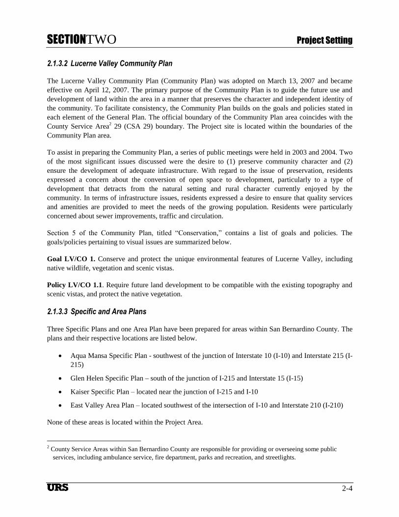
2.1.3.2 Lucerne Valley Community Plan
The Lucerne Valley Community Plan (Community Plan) was adopted on March 13, 2007 and became
effective on April 12, 2007. The primary purpose of the Community Plan is to guide the future use and
development of land within the area in a manner that preserves the character and independent identity of
the community. To facilitate consistency, the Community Plan builds on the goals and policies stated in
each element of the General Plan. The official boundary of the Community Plan area coincides with the
County Service Area2 29 (CSA 29) boundary. The Project site is located within the boundaries of the
Community Plan area.
To assist in preparing the Community Plan, a series of public meetings were held in 2003 and 2004. Two
of the most significant issues discussed were the desire to (1) preserve community character and (2)
ensure the development of adequate infrastructure. With regard to the issue of preservation, residents
expressed a concern about the conversion of open space to development, particularly to a type of
development that detracts from the natural setting and rural character currently enjoyed by the
community. In terms of infrastructure issues, residents expressed a desire to ensure that quality services
and amenities are provided to meet the needs of the growing population. Residents were particularly
concerned about sewer improvements, traffic and circulation.
Section 5 of the Community Plan, titled “Conservation,” contains a list of goals and policies. The
goals/policies pertaining to visual issues are summarized below.
Goal LV/CO 1. Conserve and protect the unique environmental features of Lucerne Valley, including
native wildlife, vegetation and scenic vistas.
Policy LV/CO 1.1. Require future land development to be compatible with the existing topography and
scenic vistas, and protect the native vegetation.
2.1.3.3 Specific and Area Plans
Three Specific Plans and one Area Plan have been prepared for areas within San Bernardino County. The
plans and their respective locations are listed below.
Aqua Mansa Specific Plan - southwest of the junction of Interstate 10 (I-10) and Interstate 215 (I-
215)
Glen Helen Specific Plan – south of the junction of I-215 and Interstate 15 (I-15)
Kaiser Specific Plan – located near the junction of I-215 and I-10
East Valley Area Plan – located southwest of the intersection of I-10 and Interstate 210 (I-210)
None of these areas is located within the Project Area.
2 County Service Areas within San Bernardino County are responsible for providing or overseeing some public
services, including ambulance service, fire department, parks and recreation, and streetlights.

SECTIONTWO Project Setting
2-5
2.1.3.4 Zoning Ordinance
The County of Santa Bernardino’s Development Code implements the goals and policies of the General
Plan by regulating land uses within the unincorporated areas of the County. Each piece of property is
within a “zone” or “land use” designation which describes the rules under which that land may be used.
These districts, such as “RS” for single-family residential or “CG” for general commercial, generally
cover the range of uses allowable within the land use district. The Development Code also establishes
specific development standards for each designation and the procedures to follow in order to approve a
particular use. The County’s Development Code chapters specifically apply to the regulation of Solar
Energy projects and lighting/glare. The proposed Project’s applicable development standards are:
Ordinance Standard 84.29.040 Solar Energy Development Standards – The purpose of this
Chapter is to establish standards and permit procedures for the establishment, maintenance and
decommissioning of renewable energy generation facilities. These regulations are intended to
ensure that renewable energy generation facilities are designed and located in a manner that
minimizes visual and safety impacts on the surrounding community.
Ordinance Standard 83.07.040 Glare and Outdoor Lighting – The purpose of this Chapter is
to encourage outdoor lighting practices and systems that minimize light pollution, glare, and light
trespass while conserving energy and resources in consideration of nighttime safety, visibility,
utility, and productivity.

SECTIONTHREE Assessment Methodology
3-1
SECTION 3 ASSESSMENT METHODOLOGY
This VIA was prepared according to Bureau of Land Management (BLM) Contrast Rating procedures
(BLM 1986). Significance of impacts was determined using CEQA criteria, and is informed by the
Contrast Rating criteria.
3.1 STUDY AREA
The Study Area for visual resources included all lands located within a five-mile radius of the proposed
project. Figure 2 provides US Census data on the population density of the area surrounding the Project.
As shown, the Lucerne Valley is sparsely populated, with less than 100 residents per square mile.
Using Geographic Information Systems (GIS), a viewshed analysis was completed to identify locations
within this area where the project could theoretically be seen (Figure 3). This analysis determined the
theoretical project visibility based on the relationship between topography, height of the proposed project,
and average eye height of the viewer. For the purpose of this analysis, input parameters were defined as
follows: eye level of 5.5 feet and maximum solar photovoltaic receiver height of 15 feet (most project
components would be less than the seven feet tall fence height). The resulting “Seen Area” (or viewshed),
represents areas that may have views of the project; however it does not represent any measure of
detectability of project components. Furthermore, the viewshed analysis does not account for localized
visual obstructions such as vegetation and/or structures. Therefore the viewshed analysis was used to
assess potential visibility of the project, and to better understand viewer experience within the landscape.
For example, roadway travelers may experience intermittent views of the project where topography is
variable, and more prolonged views where topography is flat.
3.2 KEY OBSERVATION POINTS
The visual resource impact analysis was completed from Key Observation Points (KOPs) selected to
represent common and/or sensitive viewer locations within the Study Area (Figure 4). Based on
information gleaned from land use data, field inspection, and input from the County of San Bernardino
Land Use Services Department, a total of two KOPs were selected. The KOPs differ by landscape
analysis factors, such as their distance from the project, predominant angle of observation, dominant use
(i.e., recreation or travel), and average travel speed at which the project could be viewed. All KOPs were
selected from areas within viewing distance of the proposed project. The distance of the KOP to the
Project was documented through desktop mapping using georeferenced photo points in relation to the
boundaries of the Project. Photos were obtained at all KOPs. Landscape character and analysis factors for
areas represented by each KOP are summarized in Section 4.2, below.
3.3 EXISTING CONDITIONS
Existing visual resource conditions were assessed through field observations, and documented from
established KOPs. Data collection focused on establishing a baseline for visual resource conditions,
developing assumptions of visual sensitivity within the study area, and documenting visual distance zones
within the Study Area.

?åE
SOURCES: USGS Quads: White Horse Mountain,Grand View Mine, Lucerne Valley, Cougar Buttes, Fawnskin,Big Bear City, Old Woman Springs, Rattlesnake Canyon.Lucerne Valley, 1978. Project Sites (BSE, 2012),Aerial (Bing Maps, 2012) Population Density (ESRI, 2010).
POPULATION DENSITY MAP
MARATHON
SAN BERNARDINO COUNTY, CA
CREATED BY: DT
PM: BM PROJ. NO: 28907132.23000
FIG. NO:
2SCALE: 1" = 2.5 miles (1:158,400)
1.25 0 1.25 2.5 Miles
O
SCALE CORRECT WHEN PRINTED AT 8.5X11Pa
th:
G:\
gis
\pro
ject
s\1
57
7\2
89
07
13
2\m
ap
_d
ocs
\mxd
\MA
RA
TH
ON
_P
op
ula
tio
n_
Den
sity
_F
igu
re.m
xd
, d
avi
d_
trze
cia
k, 6
/15
/20
12
, 1
2:5
9:4
4 P
M
DATE: 6/15/2012
Marathon, 0449-172-75, 0449-631-02
Block Groups
2010 Population per Square Mile
100,001 to 382,183
25,001 to 100,000
10,001 to 25,000
1,001 to 10,000
101 to 1,000
0 to 100
Zero Population

U.S. Forest Service Land
?åE
Bighorn Mountain Wilderness
Carbonate Endemic Plants
Ord-Rodman DWMA
SOURCES: USGS Quads: White Horse Mountain,Grand View Mine, Lucerne Valley, Cougar Buttes, Fawnskin,Big Bear City, Old Woman Springs, Rattlesnake Canyon.. Project Sites (BSE, 2012), Aerial (Bing Maps, 2012).BLM Wilderness Area, BLM Designated Areas of Environmental Concern, BLM Land Ownership (BLM)USFWS Critical Habitats (USFWS)US Forest Service Land (USFS)
VIEWSHED ANALYSIS
MARATHON
SAN BERNARDINO COUNTY, CA
CREATED BY: DT
PM: BM PROJ. NO: 28907132.23000
FIG. NO:
3SCALE: 1" = 2 miles (1:126,720)
1 0 1 2 Miles
O
SCALE CORRECT WHEN PRINTED AT 8.5X11Pa
th:
G:\
gis
\pro
ject
s\1
57
7\2
89
07
13
2\m
ap
_d
ocs
\mxd
\MA
RA
TH
ON
_V
iew
shed
_F
igu
re.m
xd,
da
vid
_tr
zeci
ak,
6/1
5/2
01
2,
12
:59
:01
PM
DATE: 6/15/2012
Marathon, 0449-172-75, 0449-631-02
US Bureau of Land Management Property
BLM Wilderness Area
BLM Designated Areas of Environmental Concern
USFWS Critical Habitats
U.S. Forest Service Land Boundary
Visibility of PV Equipment
Visible
Not Visible

!\
!\
U.S. Forest Service Land
?åE
KOP 1
KOP 2
Bighorn Mountain Wilderness
Carbonate Endemic Plants
Ord-Rodman DWMA
SOURCES: USGS Quads: White Horse Mountain,Grand View Mine, Lucerne Valley, Cougar Buttes, Fawnskin,Big Bear City, Old Woman Springs, Rattlesnake Canyon.. Project Sites (BSE, 2012), Aerial (Bing Maps, 2012).BLM Wilderness Area, BLM Designated Areas of Environmental Concern, BLM Land Ownership (BLM)USFWS Critical Habitats (USFWS)US Forest Service Land (USFS)
KEY OBSERVATION POINTS
MARATHON
SAN BERNARDINO COUNTY, CA
CREATED BY: DT
PM: BM PROJ. NO: 28907132.23000
FIG. NO:
4SCALE: 1" = 2 miles (1:126,720)
1 0 1 2 Miles
O
SCALE CORRECT WHEN PRINTED AT 8.5X11Pa
th:
G:\
gis
\pro
ject
s\1
57
7\2
89
07
13
2\m
ap
_d
ocs
\mxd
\MA
RA
TH
ON
_P
ho
to_
Po
ints
_F
igu
re.m
xd
, d
avi
d_
trze
cia
k,
6/1
5/2
01
2,
1:0
0:3
7 P
M
DATE: 6/15/2012
Marathon, 0449-172-75, 0449-631-02
!\ Key Observation Point
US Bureau of Land Management Property
BLM Wilderness Area
BLM Designated Areas of Environmental Concern
USFWS Critical Habitats
U.S. Forest Service Land Boundary
Visibility of PV Equipment
Visible
Not Visible

SECTIONTHREE Assessment Methodology
3-5
Baseline for visual resources was established by describing existing landforms, vegetation, and structures
using the basic components of form, line, color, and texture (Section D-BLM Contrast Rating Form 8400-
5).
Visual sensitivity is defined as a measure of public concern for scenic quality. Based on criteria defined
by the Bureau of Land Management (BLM 1986), visual sensitivity was estimated as high, medium or
low using criteria described below:
Type of Users – Visual sensitivity is expected to vary by type of user. For example, recreational
sightseers may be highly sensitive to any changes in visual quality, whereas workers who pass
through the area on a regular basis may not be as sensitive to change.
Amount of Use – Visual sensitivity is expected to vary by amount of use. For example, areas seen
and used by large numbers of people are potentially more sensitive. Protection of visual values
usually becomes more important as the number of viewers increase.
Public Interest – The visual quality of an area may be of concern to local, State, or National
groups. Indicators of this concern are usually expressed in public meetings, letters, newspaper or
magazine articles, newsletters, land-use plans, or public controversy created in response to
proposed activities that is perceived to result in change to the landscape character.
Adjacent Land Uses – The interrelationship with land uses in adjacent lands can affect the visual
sensitivity of an area. For example, an area within the viewshed of a residential area may be very
sensitive, whereas an area surrounded by commercially developed lands may not be visually
sensitive.
Special Areas – Management objectives for special areas such as Natural Areas, Wilderness
Areas or Wilderness Study Areas frequently require special consideration for the protection of the
visual values. This designation does not necessarily indicate high scenic quality, but rather the
potential for management objectives to be aimed at preservation of the natural landscape setting.
Other Factors – Additional information, such as research or studies that includes indicators of
visual sensitivity, should be included in the sensitivity level analysis when available.
Distance zones represent the distance from which the landscape is most commonly viewed, and are
established by buffering common travel routes and viewer locations at distances of 3, 5, and 15 miles.
Because of the relationship between distance and viewer perception, distance zones can also be used to
estimate visual thresholds, as a viewer’s ability to detect attributes of form, line, color, and texture is
expected to decrease with distance. Distance zones are defined as follows (BLM 1986):
Foreground-Middleground. This is the area that can be seen from a particular location to a
distance to five miles. The outer boundary of this distance zone is described as the point where
the texture and form of individual plants are no longer apparent in the landscape. In some areas,
atmospheric conditions can reduce visibility and shorten the distance normally covered by each
zone.
Background. The background includes locations that can be seen between a distance of 5 and 15
miles. The background zone does not include areas in the background which are so far distant that

SECTIONTHREE Assessment Methodology
3-6
the only thing discernible is the form or outline. In order to be included within this distance zone,
vegetation should be visible at least as patterns of light and dark.
Seldom-Seen Zone. These are areas that are generally not visible within the foreground-
middleground and background, or portions which are visible but beyond the background distance
of 15 miles.
3.4 VISUAL SIMULATIONS
Visual simulations were developed to represent the appearance of the proposed Project from KOP 1 and
KOP 2. To ensure a high degree of visual accuracy in the visual simulations, computer-aided drafting and
design (CADD) equipment, GIS, and the use of a global positioning system (GPS) allowed for life-size
modeling within the computer. This translated to using real-world scale and coordinates to locate Project
facilities, other site data, and the camera locations corresponding to three-dimensional (3D) simulation
viewpoints.
A GIS site map was imported as a background reference. CADD drawings of proposed Project facilities
were placed on top of the project site map in GIS. Locations of the KOPs were also input into GIS. The
camera positioning information was then referenced to the 3D data set. The 3D massing models of the
proposed Project (including ancillary facilities) are generated in real-world coordinates, scaled, and input
into GIS.
A Nikon 6.1 megapixel digital camera set to take a 19.2-millimeter lens image was used consistently
throughout the process. This lens setting selection allows for viewing of the computer-generated model in
the same way that the Project would be viewed in the field. The photographs were imported into the 3D
database and loaded as an environment within which the view of the 3D model was generated. To
generate the correct view relative to the actual photograph, the electronic camera was placed at a location
(within the computer) from where the photograph was taken. From there, the 3D wire frame model was
displayed on top of the existing photo so that proper alignment, scale, angle, and distance could be
verified. When all lines of the wire frame model exactly matched the photograph, the camera target
position was confirmed.
Final simulations were created using CADD files obtained from the Project engineer to remain consistent
with general Project development engineering. Once field KOP location photos and coordinates for photo
locations were gathered, these were incorporated into the final simulation production. The processes
described above relate to general simulation construction and are included to assist the reader in
understanding the procedures followed to create simulations.
3.5 IMPACT ANALYSIS
3.5.1 Visual Contrast Rating
The BLM Contrast Rating procedure was used to determine visual contrast that may result from the
construction and operation of the project based on photo simulations depicting project features. This
method assumes that the extent to which the project results in significant impacts to visual resources is a
function of the visual contrast between the project and the existing landscape character. Impact

SECTIONTHREE Assessment Methodology
3-7
determinations are based on the identified level of contrast with these elements, and are not a measure of
the overall attractiveness of the project (BLM 1986).
At each KOP, existing landforms, vegetation, and structures were described using the basic components
of form, line, color, and texture. Project features were then evaluated using simulations, and described
using the same basic elements of form, line, color, and texture. The level of perceived contrast between
the proposed project and the existing landscape was then classified using the following definitions:
None: The element contrast is not visible or perceived.
Weak: The element contrast can be seen but does not attract attention.
Moderate: The element contrast begins to attract attention and begins to dominate the
characteristic landscape.
Strong: The element contrast demands attention, would not be overlooked, and is dominant
in the landscape.
The level of contrast was assessed for all project components used during construction, operation and
maintenance, and decommissioning of the proposed project. For purposes of this analysis, potential
impacts resulting from glint and glare are discussed in terms of elements of color and texture. The level of
visual contrast expected to result from construction or decommissioning related activities was estimated
based on knowledge of anticipated activities and equipment that would be present. No photo simulations
of construction or decommissioning were developed. Contrast Rating Forms are provided in Appendix A.
3.5.2 Determination of Significance
The determination of significance was completed using the CEQA significance criteria. Per CEQA,
impacts to visual resources would be significant if a Project results in:
1. A substantial adverse effect on a scenic vista.
2. Substantial damage to scenic resources, including, but not limited to, trees, rock
outcroppings, and historic buildings.
3. Substantial degradation of the existing visual character or quality of the site and its
surroundings.
4. Creation of a new source of substantial light or glare that would adversely affect day or
nighttime views in the area.
The degree to which potential impacts were considered significant was based on the outcome of the visual
contrast rating, and in consideration of landscape analysis factors such as landscape type (i.e., panoramic
vs. enclosed or focal), scale, dominance, duration of view, and predominant angle of observation in
relation to viewer sensitivity.

SECTIONFOUR Affected Environment
4-1
SECTION 4 AFFECTED ENVIRONMENT
The following sections discuss the existing visual character and quality of the physical and built
environment within vicinity of the Project.
4.1 REGIONAL AND SITE SETTING
The Study Area is situated in the Lucerne Valley area of the western Mojave Desert. The Mojave Desert
is a subsection of the Basin and Range Physiographic Province, which is characterized by long, north-
south-trending mountain ranges separated by broad valleys. The project site is best described as vacant
desert and is vegetated with scrubby drought tolerant plants such as creosote bush and Joshua Trees.
Character photos 1 and 2 below demonstrate the visual nature of the Project vicinity (Figures 5 and 6).
The project site is located approximately 3.5 miles north of the San Bernardino National Forest. National
Forests are managed by the United States Forest Service (USFS) and often contain hiking and Off
Highway Vehicle (OHV) use trails that are maintained USFS. The Mitsubishi Mining Company operates
a large-scale aggregate mine just south of the boundary of the San Bernardino National Forest, and
adjacent to the western edge of SR-18. A large electrical substation is located north of the Mitsubishi
Mine, along the west side of SR-18 just south and west of its intersection with Camp Rock Road.
Character Photo 3 (Figure 7) was taken facing southwest from the intersection of SR-18 and Camp Rock
Road. Character Photo 4 (Figure 8) was taken from a location adjacent to the western boundary of the
Marathon Project. This image faces south toward the Mitsubishi Mine and displays the large surficial scar
that is visible along the face of the mountain. This photo also demonstrates the flat and open nature of the
Project site.

SECTIONFOUR Affected Environment
4-2
Figure 5 - Character Photo 1
Figure 6 - Character Photo 2

SECTIONFOUR Affected Environment
4-3
Figure 7 - Character Photo 3
Figure 8 - Character Photo 4

SECTIONFOUR Affected Environment
4-4
The project site is located on a broad gently sloping bajada of alluvial material originating from the San
Bernardino Mountains to the south. Elevation at the site ranges from approximately 3,240 feet above sea
level (asl) at its northwest corner up to 3,346 asl at its southeast corner. The topography is generally flat,
with a slope of about 3.6 percent toward the north-northwest.
The site is bordered by vacant open space as well as sparse residential development. The Big Bear Area
Regional Wastewater Agency operates a balance pool at the northeast corner of the Project boundary. The
vacant land both north and south of the site is subdivided into lots ranging from five to 10 acres in size;
however, to date, no development has occurred. Joshua Street forms part of the western boundary of the
project site, and land to the west of Joshua Street is subdivided into five-acre lots. Approximately one-
quarter of the lots have been developed with single family residences. One residence is located across
Joshua Street to the west, and about a dozen others are within one quarter mile. To the east, across Camp
Rock Road, the land is subdivided into lots of 18 to 19 acres in size; however no development (residential
or other) has occurred.
4.2 PROJECT-LEVEL CONDITIONS
4.2.1 Key Observation Point 1
KOP 1 is located at the intersection of Camp Rock Road and SR-18. This KOP is representative of views
to the north toward the central portion of the Lucerne Valley, and is primarily experienced by motorists
traveling on SR-18 (Figure 9). From SR-18, the Fry Mountains are visible in the background, while the
broad and open landscape of the Lucerne Valley occupies the fore and midground. Telephone and power
poles/wires are visible in the immediate foreground of this KOP and from most locations along SR-18.
These poles and wires attract the viewer’s eye due to their proximate and clustered arrangement at KOP 1
in particular. The intersection of Camp Rock Road and SR-18 is located approximately 2.2 miles south of
the project site, and is at a higher elevation than the project site. The viewshed from this location lacks
movement and mostly consists of pale shades of brown, gray and green colors indicative of the dry, high
desert landscape. The rocky/sandy soil appears course in texture, and the low lying/scrubby vegetation
reinforces this rough textural component. No buildings or other structural development are tall enough to
obstruct views from this location, though scattered residences are located in the area surrounding the
Project, and particularly concentrated north of the project along SR-247. Dirt roadways form long linear
features on the distant horizon. These roadways, which are lighter shades of brown than the surrounding
landscape, draw the viewers’ attention north and upward toward the Fry Mountains. Other anthropogenic
structures and influences within this viewshed include random and sparsely located residential/ranchette
style development where structures and fence lines disrupt the continuity of the open desert landscape in
between them.
Primary viewers from this KOP will be motorists traveling on SR-18. According to Caltrans data, the
portion of SR-18 south of its intersection with SR-247 has a peak month Average Daily Trip (ADT) count
of 5,400 travelers. Views of the project area for motorists traveling north and south on SR-18 or Camp
Rock Road are considered transient. Views toward the Project from locations south of the Project will be
experienced at an oblique angle. Because SR-18 is eligible for designation as a State Scenic Highway, and
because it is listed as a scenic roadway in the San Bernardino County General Plan, overall viewer
sensitivity is assumed high.

SECTIONFOUR Affected Environment
4-5
Figure 9 – KOP 1 Existing Conditions

SECTIONFOUR Affected Environment
4-6
4.2.2 Key Observation Point 2
KOP 2 is located on the north facing slope of Blackhawk Mountain, approximately 3.8 miles south of the
Project. KOP 2 faces northwest toward the open expanse of the Lucerne Valley. This KOP is located on a
USFS access road and offers unobstructed and panoramic views of the Lucerne Valley and Fry Mountains
(Figure 10). From this elevated perspective, residential and commercial development in the Lucerne
Valley area appears small in scale relative to the panoramic landscape. This KOP includes views of the
foothills of Blackhawk Mountain, located in the immediate foreground. This landform contributes
variability and interest to the form, line, color, and texture of the visual environment. The rolling hills and
ridgelines associated with the foothills create slopes and shadows that draw the viewers’ attention to the
lower portion of the viewshed. These slopes and shadows also influence the color scheme of this
landscape by adding variability and gradual movement depending on the angle of the sun throughout the
day. The foothills also distinctly separate the boundary line between the mountainous and uneven
topography and the valley and its flat and expansive geography. This trend lends the landscape a
horizontal element, which is reinforced by the horizon line of the Fry Mountains in background. While
the shadowing creates visual complexity within the landscape, the predominant colors that pervade this
landscape include various shades of dark to light brown, pale green, and gray. Depending on ambient
conditions, and particularly during summer months when the weather is humid, a haze can develop within
this landscape that further washes out and fades the color distinctions between the dominant shades of
brown and green. Similar to KOP 1, the long linear dirt roadways in the far distance draw the viewer’s
eye northward toward the horizon line.
Primary viewers from this KOP are assumed to include OHV enthusiasts, hikers, and USFS employees
and volunteers that maintain the access roads. The USFS is charged with maintaining “the health,
diversity, and productivity of the Nation’s forests and grasslands to meet the needs of present and future
generations” (USFS website, 2012). Other than USFS employees, typical viewers who utilize the road
will be doing so for some kind of recreational purpose; these users are considered to have high levels of
viewer sensitivity.

SECTIONFOUR Affected Environment
4-7
Figure 10 – KOP 2 Existing Conditions

SECTIONFIVE Environmental Consequences
5-1
SECTION 5 ENVIRONMENTAL CONSEQUENCES
The following section assesses the degree of visual contrast that would result from the proposed Project.
The analysis includes the potential for the project to create glint and glare, and evaluates the extent to
which viewers could adversely respond to such changes. This discussion is divided into temporary
construction-related impacts, and permanent impacts that would occur during operation of the Project.
5.1 CONSTRUCTION-RELATED IMPACTS
Short-term visual impacts would result from project construction. Construction-related actions will
generally be on or near the ground surface and will not involve significant vertical components. The
construction impacts are expected to be limited to areas within the foreground-middleground. Short-term
visual impacts would be associated with the presence of equipment and materials (e.g., graders,
excavators, dozers, backhoe/front end loaders, trucks, etc.) required for excavation/grading and
construction activities. Construction-related equipment and machinery could attract views toward the site
as a result of movement. Other potential visual impacts would result from construction staging activities
proposed on the project site including the stockpiling of construction materials and the placement of
construction equipment. However, due to the temporary nature of the construction activities (i.e., 6-9
month construction window), such as the staging of equipment and stockpiling of materials, effects on
visual resources as a result of those activities are not considered substantially adverse under CEQA.
5.2 OPERATIONAL IMPACTS
Visual effects of the project are measured by the degree of contrast between visual elements of the project
and that of the existing landscape. The results of the Visual Contrast Rating completed for KOPs 1 and 2
are presented below. Contrast Rating Forms are presented in Appendix A.
5.2.1 KOP 1
From this KOP, the Project is expected to result in a weak contrast in form, line, color and texture against
the existing landscape. The simulation suggests the proposed solar photovoltaic panels will appear as a
dark angular band in the midground this particular viewshed (Figure 11). As shown in the simulation, the
solar panels, being low in height, rise just above the scrubby vegetation in the foreground. Existing
structures such as power lines and residences are also located in the fore, mid, and background of this
viewshed. These structures consist of various shades of brown, so the black associated with the panels has
a weak contrast with these existing structural elements. Additionally, the texture of the panels as
represented in the simulation, represent a weak contrast to the texture of the existing structures and
vegetation. The solar panels would be smooth compared to the telephone poles, roads, and residences
which appear coarse- to moderately-grained. The Project would have a weak contrast with the dominant
lines of the viewshed as it would create a moderately strong horizontal band. However, the horizontal
nature of the line tends to blend with the overall horizontal-trending landscape.
The Project would comprise a relatively small portion of the panoramic and expansive views from SR-18.
Furthermore, typical views of the Project would occur from an oblique angle. As a result, although the
proposed project is expected to result in a weak level of contrast with the existing visual environment, this

SECTIONFIVE Environmental Consequences
5-2
level of change would be largely absorbed by the panoramic scale of the viewshed and local topographic
features.
5.2.2 KOP 2
From this KOP, the Project is expected to result in a moderate contrast to the predominant color and
texture of the landscape. Simulations prepared for this KOP (Figure 12) suggest the Project will appear as
a dark angular/geometric feature on the landscape. The existing landscape is predominately composed of
faded browns, greens, grays, and beige. Consequently, the black color of the PV panels results in
moderate color contrast to the visual landscape. This color distinction is more noticeable from the
elevated position of KOP 2, which allows the viewer to look down on the open landscape of the Lucerne
Valley below. Additionally, the smooth texture of the panels represents a moderate contrast with the
mixture of moderate to more finely grained texture of the overall landscape. The smoothness of the PV
panels contrasts with the stippled and somewhat rough nature of the vegetation surrounding this location.
As such, the Project would introduce an ordered, smooth and dark shape within an immediate landscape
that is a mixture of moderately grained, gray, brown, green and beige materials. Visible project features
would have weaker degrees of contrast with the form and line of the surrounding land and vegetation.
5.2.3 Lighting and Glare
The Project’s lighting system will provide operation and maintenance personnel with illumination for
both normal and emergency conditions. Lighting will be designed to provide the minimum illumination
needed to achieve safety and security objectives and will be directed downward and shielded to focus
illumination on the desired areas only and avoid light spillage on adjacent properties. Project lighting will
be located at each inverter station and the project switchyard. Lighting will be no brighter than required to
meet safety and security requirements, and the lamp fixtures and lumens will be selected accordingly. All
project lighting will be switched and without timers.
For the purposes of this analysis, the potential for the Project to create significant impacts in terms of
glare was considered as factor of color and texture. Due to the dark and relatively smooth nature of the
Project, it is assumed the Project has the capacity to create some measure of glare within the existing
visual environment. However, this is not expected to be a significant impact for several reasons. First,
when viewed at an average height of 5.5 feet (as from KOP 1), the Project is not highly visible within the
commonly viewed landscape. As such, this limits and reduces the potential for glare to occur in areas
where the greatest concentration of viewers would have exposure to the Project itself. It is assumed that
from an elevated position (such as from KOP 2), the Project could have the capacity to create visible glare
at various times of the day and under certain ambient lighting conditions. However, due to the limited
number of viewers that will have superior angled views toward the Project. In terms of glare that could
result from Project lighting, the facility is unmanned, and few if any lights will be switched on at night.
Therefore, the Project is not expected to generate a significant glare impact.

SECTIONFIVE Environmental Consequences
5-3
Figure 11 – KOP 1 Proposed Conditions

SECTIONFIVE Environmental Consequences
5-4
Figure 12 – KOP 2 Proposed Conditions

SECTIONFIVE Environmental Consequences
5-5
5.3 CUMULATIVE IMPACTS
This section analyzes the cumulative impacts of the Project in conjunction with the proposed Agincourt
Solar Project. The Agincourt Solar Project would be located approximately 1,300 feet south of the
Marathon Solar Project. The Agincourt Solar Project will use the same solar PV technology as the
Marathon Solar Project, and as such the two facilities would appear visually similar. The Agincourt Solar
Project is proposed to occupy approximately 59 acres of a 79.2 acre site. Agincourt Solar is proposed to
contain fewer solar PV panels, and occupy a smaller area of land compared to Marathon Solar. The
Agincourt Solar Project is expected to generate approximately 10 MW of AC power. No new offsite
transmission lines or other linear facilities are proposed as part of the project.
A viewshed analysis was run to identify the areas where the two projects would be visible (Figure 13).
Additionally, visual simulations depicting the cumulative visual impact of both the Marathon and
Agincourt Solar projects were prepared from KOP 1 and KOP 2. Contrast Rating forms were completed
to assess the cumulative visual impact of both Projects.
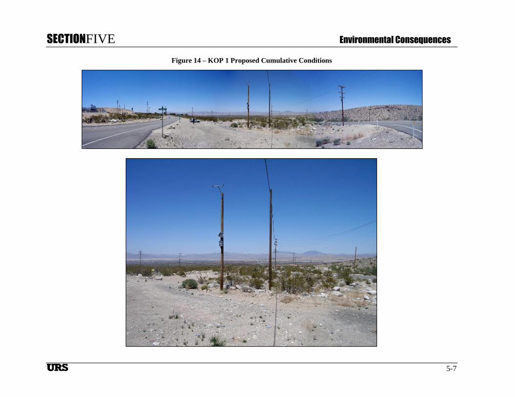
5.3.1 KOP 1 - Cumulative Impacts
Visual simulations prepared for KOP 1 suggest construction of both the Agincourt Solar Project and the
Marathon Solar Project would incrementally increase visual impacts of the Marathon Solar Project alone.
A Contrast Rating analysis was prepared to assess the cumulative visual impact of both projects from this
KOP. From this oblique angle at KOP 1, the proposed solar photovoltaic panels associated with the
Agincourt Project appear as a somewhat wider, dark and angular band in the midground the viewshed
(Figure 14). The boundaries between the two Projects are difficult to discern visually based on their
proximity to one another, and as a result of the angle of observation from this KOP. Based on this
analysis, the cumulative and combined visual impact of the Marathon and Agincourt Solar Projects is
considered less than significant from KOP 1.
5.3.2 KOP 2 - Cumulative Impacts
Visual simulations prepared for KOP 2 suggest construction of the Agincourt Solar Project, in addition to
the Marathon Solar Project, would incrementally increase visual impacts of the Marathon Solar Project
alone. A Contrast Rating analysis was prepared to assess the cumulative visual impact of both projects
from this KOP). The visual simulations suggest that the open space between the Agincourt and Marathon
Solar Projects is more noticeable from the elevated perspective of KOP 2 (Figure 15). The PV fields
associated with the Agincourt Solar Project appear as several rectangular shapes surrounding the
Marathon Project, and therefore emulate its form and color. From the distance and elevation of KOP 2,
the Marathon and Agincourt projects appear as a relatively small part of the panoramic landscape. Based
on this analysis, the cumulative and combined visual impact of the Marathon and Agincourt Solar
Projects is considered less than significant from KOP 2.

U.S. Forest Service Land
?åE
Bighorn Mountain Wilderness
Carbonate Endemic Plants
Ord-Rodman DWMA
SOURCES: USGS Quads: White Horse Mountain,Grand View Mine, Lucerne Valley, Cougar Buttes, Fawnskin,Big Bear City, Old Woman Springs, Rattlesnake Canyon.. Project Sites (BSE, 2012), Aerial (Bing Maps, 2012).BLM Wilderness Area, BLM Designated Areas of Environmental Concern, BLM Land Ownership (BLM)USFWS Critical Habitats (USFWS)US Forest Service Land (USFS)
CUMULATIVE VIEWSHED ANALYSIS
AGINCOURT & MARATHON
SAN BERNARDINO COUNTY, CA
CREATED BY: DT
PM: BM PROJ. NO: 28907132.23000
FIG. NO:
13SCALE: 1" = 2 miles (1:126,720)
1 0 1 2 Miles
O
SCALE CORRECT WHEN PRINTED AT 8.5X11Pa
th:
G:\
gis
\pro
ject
s\1
57
7\2
89
07
13
2\m
ap
_d
ocs
\mxd
\Vie
wsh
ed_
Fig
ure
_B
oth
.mxd
, d
avi
d_
trze
cia
k, 6
/15
/20
12
, 1
:01
:37
PM
DATE: 6/15/2012
Agincourt, 0449-641-27, 0449-641-04
Marathon, 0449-172-75, 0449-631-02
US Bureau of Land Management Property
BLM Wilderness Area
BLM Designated Areas of Environmental Concern
USFWS Critical Habitats
U.S. Forest Service Land Boundary
Visibility of PV Equipment
Visible
Not Visible
SECTIONFIVE Environmental Consequences
5-7
Figure 14 – KOP 1 Proposed Cumulative Conditions

SECTIONFIVE Environmental Consequences
5-8
Figure 15 – KOP 2 Proposed Cumulative Conditions

SECTIONSIX Impact Significance
6-1
SECTION 6 IMPACT SIGNIFICANCE
This section provides a discussion of the significance of the project’s visual effects pursuant to CEQA.
The assessment of these impacts is structured according to the criteria set forth in Appendix G of the
CEQA Guidelines. CEQA defines a “significant effect” on the environment to mean a “substantial, or
potentially substantial, adverse change in any of the physical conditions within the area affected by the
project, including objects of historic or aesthetic significance.” (14 CCR 15382). Four questions
pertaining to visual impact and aesthetics are posed for consideration and evaluation in relation to the
Project:
1. Would the project have a substantial adverse effect on a scenic vista?
The Project would not have a substantial adverse effect on a scenic vista as no designated scenic
vistas are located within visible distance of the Project. Therefore the Project would have no
impact to a designated scenic vista.
2. Would the project substantially damage scenic resources, including, but not limited to,
trees, rock outcroppings, and historic buildings within a state scenic highway?
The Project would not substantially damage scenic resources, including but not limited to trees,
rock outcroppings, and historic buildings within a state scenic highway. SR-18 is eligible for
listing as a state scenic highway; however it has not been officially listed. Therefore the Project
would have no impact to scenic resources along a state scenic highway.
At the local level, SR-18 is designated as a “Scenic Road” within the San Bernardino County
General Plan. As motorists travel south on SR-18 toward Big Bear Lake, the Project is likely to
be visible toward the south and east for approximately 3 miles. As such, the Project has the
potential to be visible for approximately three minutes when traveling south on SR-18. However,
from this portion of SR-18, motorists will be at a lower elevation compared to the Project. As
motorists continue to travel south toward the Project, they will also be moving west and away
from the Project boundary. The combination of elevation change in relation to movement away
from the Project is likely to decrease the visibility and overall duration of view for southbound
travelers. Motorists traveling southbound on SR-18 from its intersection with SR-247 will also
have direct views of the Mitsubishi Mining Operation. The extensive and vast nature of the
visible scar on the mountains caused by this mine could attract viewer attention compared to the
brevity of views they will have toward the Project.
Motorists traveling north on SR-18 from Big Bear to Lucerne Valley will be at an elevated
position relative to the Project site. Based on the viewshed analysis and field reconnaissance
conducted by URS in coordination with the County of San Bernardino (URS, 2012), the Project
site does not appear to be visible from the mountainous portion of SR-18. While views of the
Lucerne Valley are visible from this stretch of road, the Project site itself (and much of the
southern portion of the greater Lucerne Valley) was largely screened by topographical
obstructions in the foreground of most views. As noted on the viewshed analysis, the Project does
not become visible until motorists traveling on SR-18 reach the base of the mountain and enter
the Lucerne Valley. As such, motorists traveling north will have views of the Project for
SECTIONSIX Impact Significance
6-2
approximately two miles of the entire SR-18 corridor. This equates to a possible viewing
opportunity of approximately two minutes, which is a moderate to high duration of view.
The visual contrast of the Project as viewed from KOP 1 was rated weak based on a consideration
of expected views along the length of SR-18 for north and south bound motorists. As viewed in
the simulations prepared for KOP 1, the Project does not dominate the motorist viewshed, nor is it
likely to attract particular attention. Additionally, because motorists overall view toward the
Project would be temporary and viewed at an oblique angle when traveling north or south on SR-
18, the Project would not result in adverse scenic changes to the existing visual landscape viewed
from SR-18.
Based on the analysis above, the Project would have less than significant impacts to SR-18,
which is a locally designated “Scenic Route.”
3. Would the project substantially degrade the existing visual character or quality of the site
and its surroundings?
The Project is not expected to substantially degrade the existing character or quality of the site
and its surroundings. The Contrast Rating analysis suggests the Project will have a moderate
contrast in terms of color and texture when viewed from an elevated position. However, the
Contrast Rating analysis prepared from KOP 1, which represents views of the Project for the
majority of viewers, suggests the Project will have weak contrast with the existing visual
environment. The simulations prepared for both KOP 1 and KOP 2 demonstrate the Project
largely blends with the mosaic mixture of developed and undeveloped parcels that characterize
the existing landscape. Moreover, the size and scale of the Project is small relative to the
expansive landscape that surrounds it. Consequently, the project would not dominate the views
experienced from the nearby San Bernardino Mountains (i.e., KOP 2). Recreationists in this area
would have limited opportunities to view the Project as views of Lucerne Valley are obstructed
by topography from most locations on the trail. Based on this analysis, the Project would have
less than significant impacts on the existing visual character and quality of the site and its
surroundings.
4. Would the project create a new source of substantial light and glare that would adversely
affect day or nighttime views in the area?
The Project is not expected to create a substantial new source of light or glare. The facility will be
unmanned and therefore nighttime lighting will be used to the extent needed to maintain safety
and security objectives. Lighting fixtures will be hooded and directed downward to avoid spillage
on adjacent properties. Additionally, the Project will comply with San Bernardino County
Ordinance No. 84.29.040 which regulates glare, outdoor lighting, and night sky protection. All
lighting associated with the proposed Project will be subject to County approval and compliance
with San Bernardino County requirements. As such, the Project will have less than significant
impacts in terms of lighting.
The Project is not expected to create a substantial source of glare, though it may cause glare at
various times of the day and under certain lighting conditions and from distinct viewing positions.

SECTIONSIX Impact Significance
6-3
It is recognized the simulations prepared for this Project cannot adequately account for all
ambient lighting conditions. However, because the Project is low in height, and largely blends
with the existing vegetation and structural components of this landscape, the majority of viewers
are not expected to experience increased glare as a result of the Project. Motorists traveling down
SR-18 from Big Bear to the Lucerne Valley will not have direct views of the Project from this
roadway. As such, the Project will have no impact on these viewers. As discussed in the analysis
of KOP 2 above, some sensitive viewers utilizing local trails on Blackhawk Mountain would have
elevated and clear views of the Project from certain trail locations. These viewers may experience
glare from the Project at certain times of the day under particular ambient lighting conditions,
however, due to the small scale of the Project within the larger landscape, combined with the fact
that the Project will comply with San Bernardino County Ordinance Standards 84.29.040 which
regulate glare, the Project will have less than significant impacts in terms of glare.

SECTIONSEVEN References
7-1
SECTION 7 REFERENCES
BLM. 1986. Visual Resource Management Inventory and Contrast Rating System.
BLM. 1986, Handbook H-8410-1 (Visual Resource Inventory) http://www.blm.gov/nstc/VRM/8410.html
California Public Resources Code, Section 21001(b).
California Scenic Highway Mapping System website (http://www.dot.ca.gov/hq/LandArch/
scenic_highways/index.htm). Visited May 11, 2012
Caltrans (California Department of Transportation). 1992.
______. 2010. Traffic count data.
______. Website – California Scenic Highway Mapping System: List of Eligible and Officially
Designated Routes for San Bernardino County. 2008.
CEC (California Energy Commission). 2008. Rules of Practice and Procedure and Plant Site Certification
Regulations.
County of San Bernardino General Plan. 2007. Accessed May 11, 2012.
Lucerne Valley Community Plan. 2007. Accessed May 11, 2012.
National Wild and Scenic Rivers website. (http://www.rivers.gov/wildriverslist.html). Visited May 11,
2012
National Scenic Byways website. (http://byways.org/). Visited May 11, 2012).
US Federal Highway Administration. National Scenic Byways website. http://byways.org. Visited May
11, 2012.
US National Park Service. National Scenic Trails website. http://www.nps.gov/nts/. Visited May 11,
2012.
URS Corporation. 2012. Field work, observations, research, and modeling.
SECTIONEIGHT Preparers
8-1
SECTION 8 PREPARERS
Brian Madigan, Environmental and Visual Specialist
Leslie Redford, Visual Specialist
Louise Kling, Visual Specialist
Craig Woodman, Principal Project Manager
David Trzeciak, GIS Specialist

APPENDIXA Contrast Rating Forms
Appendix A
Contrast Rating Forms

Form 8400-4
UNITED STATES
DEPARTMENT OF THE INTERIOR
BUREAU OF LAND MANAGEMENT
VISUAL CONTRAST RATING WORKSHEET
Date: 5/15/12
District/ Field Office: N/A
Resource Area: N/A
Activity (program): N/A
SECTION A. PROJECT INFORMATION
1. Project Name
Marathon Solar
4. Location
Township_________
5. Location Sketch
2. Key Observation Point
KOP 1 – SR-18
Range____________
3. VRM Class
N/A
Section___________
SECTION B. CHARACTERISTIC LANDSCAPE DESCRIPTION
1. LAND/WATER 2. VEGETATION 3. STRUCTURES
FO
RM
Flat and expansive in fore and midground
bounded by pyramidal and rough to jagged
mountains in background. Horizontal.
Non directional, amorphous. Telephone poles and dirt roads add tall
vertical and straight element to viewshed.
LIN
E Transitional edge visible from valley to
mountain area in background, otherwise
landform does not possess strong linear
elements.
Weak vertical lines created by stems of
creosote bush.
Bold, angular, hard vertical lines.
CO
LO
R Dull shades of beige and brown. Creosote appears dull shades of green mixed
with hues of red
Telephone polls are dark brown, while dirt
roads are lighter shades of brown than
surrounding desert.
TE
X-
TU
RE
Soil surface is rough to fine grained. Coarse, edgy, stippled, granular. Patchy, contrasting.
SECTION C. PROPOSED ACTIVITY DESCRIPTION
1. LAND/WATER 2. VEGETATION 3. STRUCTURES
FO
RM
Flat and expansive in fore and midground
bounded by pyramidal and rough to jagged
mountains in background. Horizontal.
Non directional, amorphous. Short, definite, solid.
LIN
E Transitional edge visible from valley to
mountain area in background, otherwise
landform does not possess strong linear
elements.
Weak vertical lines created by stems of
creosote bush.
Angular, bold, geometric, horizontal lines.
CO
LO
R Dull shades of beige and brown. Creosote appears dull shades of green mixed
with hues of red
Black, dark, strong.
TE
X-
TU
RE
Soil surface is rough to fine grained. Coarse, edgy, stippled, granular. Smooth, fine, ordered.
SECTION D. CONTRAST RATING __SHORT TERM __LONG TERM
1.
DEGREE
OF
CONTRAST
FEATURES
2. Does project design meet visual resource
management objectives? ___Yes ___No
(Explain on reverses side)
3. Additional mitigating measures recommended
___Yes ___No (Explain on reverses side)
Evaluator’s Names Date
LAND/WATER BODY (1)
VEGETATION (2)
STRUCTURES (3)
ST
RO
NG
MO
DE
RA
TE
WE
AK
NO
NE
ST
RO
NG
MO
DE
RA
TE
WE
AK
NO
NE
ST
RO
NG
MO
DE
RA
TE
WE
AK
NO
NE
EL
EM
EN
TS
FORM x X X
LINE x X X
COLOR X X X

TEXTURE x x X
SECTION D. (Continued)
Comments from item 2.
Textural and color differences between existing natural landscape and project will be most notable, yet still weak contrasting elements.
Additional Mitigating Measures (See item 3)

Form 8400-4
UNITED STATES
DEPARTMENT OF THE INTERIOR
BUREAU OF LAND MANAGEMENT
VISUAL CONTRAST RATING WORKSHEET
Date: 5/15/12
District/ Field Office: N/A
Resource Area: N/A
Activity (program): N/A
SECTION A. PROJECT INFORMATION
1. Project Name
Marathon and Agincourt Solar
4. Location
Township_________
5. Location Sketch
2. Key Observation Point
KOP 1 – SR-18
Range____________
3. VRM Class
N/A
Section___________
SECTION B. CHARACTERISTIC LANDSCAPE DESCRIPTION
1. LAND/WATER 2. VEGETATION 3. STRUCTURES
FO
RM
Flat and expansive in fore and midground
bounded by pyramidal and rough to jagged
mountains in background. Horizontal.
Non directional, amorphous. Telephone poles and dirt roads add tall
vertical and straight element to viewshed.
LIN
E Transitional edge visible from valley to
mountain area in background, otherwise
landform does not possess strong linear
elements.
Weak vertical lines created by stems of
creosote bush.
Bold, angular, hard vertical lines.
CO
LO
R Dull shades of beige and brown. Creosote appears dull shades of green mixed
with hues of red
Telephone polls are dark brown, while dirt
roads are lighter shades of brown than
surrounding desert.
TE
X-
TU
RE
Soil surface is rough to fine grained. Coarse, edgy, stippled, granular. Patchy, medium grained, contrasting.
SECTION C. PROPOSED ACTIVITY DESCRIPTION
1. LAND/WATER 2. VEGETATION 3. STRUCTURES
FO
RM
Flat and expansive in fore and midground
bounded by pyramidal and rough to jagged
mountains in background. Horizontal.
Non directional, amorphous. Short, definite, solid.
LIN
E Transitional edge visible from valley to
mountain area in background, otherwise
landform does not possess strong linear
elements.
Weak vertical lines created by stems of
creosote bush.
Angular, bold, geometric.
CO
LO
R Dull shades of beige and brown. Creosote appears dull shades of green mixed
with hues of red
Black, dark, strong.
TE
X-
TU
RE
Soil surface is rough to fine grained. Coarse, edgy, stippled, granular. Smooth, fine, ordered.
SECTION D. CONTRAST RATING __SHORT TERM __LONG TERM
1.
DEGREE
OF
CONTRAST
FEATURES
2. Does project design meet visual resource
management objectives? ___Yes ___No
(Explain on reverses side)
3. Additional mitigating measures recommended
___Yes ___No (Explain on reverses side)
Evaluator’s Names Date
LAND/WATER BODY (1)
VEGETATION (2)
STRUCTURES (3)
ST
RO
NG
MO
DE
RA
TE
WE
AK
NO
NE
ST
RO
NG
MO
DE
RA
TE
WE
AK
NO
NE
ST
RO
NG
MO
DE
RA
TE
WE
AK
NO
NE
EL
EM
EN
TS
FORM X X x
LINE X X x
COLOR X X x

TEXTURE X x
SECTION D. (Continued)
Comments from item 2.
Additional Mitigating Measures (See item 3)

Form 8400-4
UNITED STATES
DEPARTMENT OF THE INTERIOR
BUREAU OF LAND MANAGEMENT
VISUAL CONTRAST RATING WORKSHEET
Date: 5/15/12
District/ Field Office: N/A
Resource Area: N/A
Activity (program): N/A
SECTION A. PROJECT INFORMATION
1. Project Name
Marathon Solar
4. Location
Township_________
5. Location Sketch
2. Key Observation Point
KOP 2 – Blackhawk Mountain Trail
Range____________
3. VRM Class
N/A
Section___________
SECTION B. CHARACTERISTIC LANDSCAPE DESCRIPTION
1. LAND/WATER 2. VEGETATION 3. STRUCTURES
FO
RM
Flat and expansive in fore and midground
bounded by pyramidal and rough to jagged
mountains in background. Horizontal.
Non directional, amorphous. Telephone poles and dirt roads add tall
vertical and straight element to viewshed.
LIN
E Transitional edge visible from valley to
mountain area in background, otherwise
landform does not possess strong linear
elements.
Weak vertical lines created by stems of
creosote bush.
Bold, angular, hard vertical lines.
CO
LO
R Dull shades of beige and brown. Creosote appears dull shades of green mixed
with hues of red
Telephone poles are dark brown, while dirt
roads are lighter shades of brown than
surrounding desert.
TE
X-
TU
RE
Soil surface is mostly fine grained. Coarse, edgy, stippled, granular. Patchy, contrasting.
SECTION C. PROPOSED ACTIVITY DESCRIPTION
1. LAND/WATER 2. VEGETATION 3. STRUCTURES
FO
RM
Flat and expansive in fore and midground
bounded by pyramidal and rough to jagged
mountains in background. Horizontal.
Non directional, amorphous. Short, definite, solid.
LIN
E Transitional edge visible from valley to
mountain area in background, otherwise
landform does not possess strong linear
elements.
Weak vertical lines created by stems of
creosote bush.
Angular, bold, geometric.
CO
LO
R Dull shades of beige and brown. Creosote appears dull shades of green mixed
with hues of red
Black, dark, strong.
TE
X-
TU
RE
Soil surface is rough to fine grained. Coarse, edgy, stippled, granular. Smooth, fine, ordered.
SECTION D. CONTRAST RATING __SHORT TERM __LONG TERM
1.
DEGREE
OF
CONTRAST
FEATURES
2. Does project design meet visual resource
management objectives? ___Yes ___No
(Explain on reverses side)
3. Additional mitigating measures recommended
___Yes ___No (Explain on reverses side)
Evaluator’s Names Date
LAND/WATER BODY (1)
VEGETATION (2)
STRUCTURES (3)
ST
RO
NG
MO
DE
RA
TE
WE
AK
NO
NE
ST
RO
NG
MO
DE
RA
TE
WE
AK
NO
NE
ST
RO
NG
MO
DE
RA
TE
WE
AK
NO
NE
EL
EM
EN
TS
FORM X X x
LINE X X x
COLOR X X x

TEXTURE x x x
SECTION D. (Continued)
Comments from item 2.
Elevated nature of KOP offers expansive views of valley below. From this perspective, the dark color and smooth texture of the PV
panels is more pronounced compared to the lower elevation where the majority of viewers will be exposed to the Project.
Additional Mitigating Measures (See item 3)

Form 8400-4
UNITED STATES
DEPARTMENT OF THE INTERIOR
BUREAU OF LAND MANAGEMENT
VISUAL CONTRAST RATING WORKSHEET
Date: 5/15/12
District/ Field Office: N/A
Resource Area: N/A
Activity (program): N/A
SECTION A. PROJECT INFORMATION
1. Project Name
Marathon Solar
4. Location
Township_________
5. Location Sketch
2. Key Observation Point
KOP 2 – Blackhawk Mountain Trail
Range____________
3. VRM Class
N/A
Section___________
SECTION B. CHARACTERISTIC LANDSCAPE DESCRIPTION
1. LAND/WATER 2. VEGETATION 3. STRUCTURES
FO
RM
Flat and expansive in fore and midground
bounded by pyramidal and rough to jagged
mountains in background. Horizontal.
Non directional, amorphous. Telephone poles and dirt roads add tall
vertical and straight element to viewshed.
LIN
E Transitional edge visible from valley to
mountain area in background, otherwise
landform does not possess strong linear
elements.
Weak vertical lines created by stems of
creosote bush.
Bold, angular, hard vertical lines.
CO
LO
R Dull shades of beige and brown. Creosote appears dull shades of green mixed
with hues of red
Telephone poles are dark brown, while dirt
roads are lighter shades of brown than
surrounding desert.
TE
X-
TU
RE
Soil surface is mostly fine grained. Coarse, edgy, stippled, granular. Patchy, contrasting.
SECTION C. PROPOSED ACTIVITY DESCRIPTION
1. LAND/WATER 2. VEGETATION 3. STRUCTURES
FO
RM
Flat and expansive in fore and midground
bounded by pyramidal and rough to jagged
mountains in background. Horizontal.
Non directional, amorphous. Short, definite, solid.
LIN
E Transitional edge visible from valley to
mountain area in background, otherwise
landform does not possess strong linear
elements.
Weak vertical lines created by stems of
creosote bush.
Angular, bold, geometric.
CO
LO
R Dull shades of beige and brown. Creosote appears dull shades of green mixed
with hues of red
Black, dark, strong.
TE
X-
TU
RE
Soil surface is rough to fine grained. Coarse, edgy, stippled, granular. Smooth, fine, ordered.
SECTION D. CONTRAST RATING __SHORT TERM __LONG TERM
1.
DEGREE
OF
CONTRAST
FEATURES
2. Does project design meet visual resource
management objectives? ___Yes ___No
(Explain on reverses side)
3. Additional mitigating measures recommended
___Yes ___No (Explain on reverses side)
Evaluator’s Names Date
LAND/WATER BODY (1)
VEGETATION (2)
STRUCTURES (3)
ST
RO
NG
MO
DE
RA
TE
WE
AK
NO
NE
ST
RO
NG
MO
DE
RA
TE
WE
AK
NO
NE
ST
RO
NG
MO
DE
RA
TE
WE
AK
NO
NE
EL
EM
EN
TS
FORM X X x
LINE X X x
COLOR X X x

TEXTURE X x
SECTION D. (Continued)
Comments from item 2.
Additional Mitigating Measures (See item 3)