Embed Size (px)
Citation preview

Energy Supply Appendix 1
NP 2004 CBA
Newfoundland Power – 2004 Capital Budget Application Page 1 of 5
Project Title: Hydro Plant Facility Rehabilitation Location: Various Classification: Energy Supply Project Cost: $1,122,000 This project consists of a number of items as noted. (a) Pierre’s Brook – Replace Forebay Head Gate
Cost: $91,000
Description: Replace the existing head gate, gate guides and lift at the forebay intake structure including rehabilitation of the upstream stop log guides.
Operating Experience: Misaligned gate guides and water leakage around the head gate seals have rendered this structure ineffective in providing the positive water shut off required to perform maintenance and inspections of downstream facilities. An attempt to dewater the penstock in September 2002 proved unsuccessful and the subsequent binding of the gate in the misaligned guides prevented the operation of the plant for three days. The services of a diving contractor were required to open the gate. This structure is the original head gate installed when the project was commissioned in 1931.
Justification: The head gate is a critical link in the continued safe and effective operation and maintenance of the Pierre’s Brook Hydro Generator. Normal production at the Pierre’s Brook hydro facility is 25.3 GWh per year.
(b) Topsail – Replace Protection and Controls
Cost: $200,000
Description: Replace the existing governor controls and protection with Newfoundland Power’s standard design Unit Control Panel, including a Programmable Logic Controller, generator protection, digital voltage regulation, synchronizer and metering.

Energy Supply Appendix 1
NP 2004 CBA
Newfoundland Power – 2004 Capital Budget Application Page 2 of 5
Operating Experience: Newfoundland Power has an approved 2003 capital project to replace the electronic control portion of the Voest-Alpine governor system at Topsail Plant. The governor was installed by Barber Hydraulic Turbine in 1983 as part of a major plant refurbishment replacing turbine, generator, switchgear, protection and control systems. Originally the unit had difficulty synchronizing to the power system and in 1995 a modification was designed that involved filtering the output of the electronic controller with a programmable logic controller. Original equipment manufacturer (“OEM”) support for the system is no longer available and the supply of spare parts has been exhausted. Newfoundland Power has undertaken to repair electronic boards in house for the equipment, however, repairing the electronics has become increasingly difficult as the discrete components and integrated circuits are no longer being manufactured.
The project for 2003 involves the replacement of the function provided by the electronic
governor with a similar function relocated to the programmable logic controller (PLC) system. Detailed engineering design began early in 2003 for this project during which it became evident that the existing PLC equipment cannot support the complete governor function, and as a result, additional PLC hardware is required.
During the design phase, a review of the plant operators log identified that most of the 115
unscheduled plant outages were related to protection and control system failures. The inability to filter out transient losses of the speed signal and the instantaneous spiking of the bearing oil and temperature readings accounted for 42% of unit trips over the previous five years. The control of the pressure relief valve accounted for another 17% of unit trips and created another significant design issue to be addressed.
In order to address the problems noted above the scope of the necessary work has
significantly expanded, making it impossible to complete the project within the original $230,000 budget. Therefore a decision has been made to carry over the original project to 2004 as a part of a larger project to complete the overall work. The combined budget for the larger project is $430,000.
Justification: Normal production at the Topsail plant is 14.2 GWh of energy annually.
The governor is a critical system and the generator cannot be operated without it. Therefore, to ensure the reliable production of energy from this facility the equipment must be replaced. See Attachment A, Engineering Review – Topsail Plant Governor, Protection and Control System.
Energy Supply Appendix 1
NP 2004 CBA
Newfoundland Power – 2004 Capital Budget Application Page 3 of 5
(c) Morris – Replace Turbine Runner Seals
Cost: $107,000
Description: Replace the mild carbon steel turbine runner stationary seals with either Type 410 stainless steel or ASTM B271 centrifugally cast nickel-aluminum-bronze alloy stationary seals. Operating Experience: The Morris turbine was installed as a new plant in 1983 by Barber Hydraulic Turbines. The turbine is a horizontal Francis Turbine. In April 2000, operators started to experience problems with the wicket gate operating ring jamming and acting sluggishly. The turbine was inspected and it was found that the carbon steel stationary seals had corroded, rust had accumulated, the two ends of the wicket gates were getting jammed in between the two stationary seals and the seals were in need of replacement. Justification: Normal production at the Morris plant is 7.2 GWh of energy annually. The turbine runner stationary seals are critical to the operation of the plant. Therefore, to ensure the reliable production of energy from this facility, the equipment must be replaced. See Attachment B, Morris Plant Turbine & Stationary Seal Inspection.
(d) Rattling Brook – Rewind Generator G1 Cost: $407,000 Description: Rewind the stator coils in generating unit G1. This involves the disassembly of the generator, the removal of the stator winding, transport to a facility equipped for the work, transport back to site, installation and realignment. Operating Experience: In 2002 the generator winding in unit G2 failed during a full load rejection. Testing revealed that a turn-to-turn fault had developed in the windings and a complete rewind of the stator was required. Unit G1 is identical in construction to unit G2, and over its forty-five year life has been exposed to a similar operating environment. Concern exists for the condition of generator windings on generators such as G1 that have exceeded their estimated life expectancy as established by the Institute of Electrical and Electronic Engineers (IEEE).

Energy Supply Appendix 1
NP 2004 CBA
Newfoundland Power – 2004 Capital Budget Application Page 4 of 5
Justification: Rattling Brook generating station is an important source of energy to the Province, with normal hydro production of 69.4 GWh annually. This is Newfoundland Power’s largest producing plant. There are times during the year when water flows are such that both generating units are required. An unplanned outage due to the loss of the generator winding on G1 would result in the loss of energy over the period necessary to effect the repair.
(e) Various Plants – Replace Cooling Coils
Cost: $69,000 Description: Replace bearing cooling coils and install bearing oil level controls and bearing cooling water flowmeters and controls. In 2004 cooling coils will be replaced in Rocky Pond, Rattling Brook, Cape Broyle and Pierre’s Brook.
Operating Experience: Since 1997 we have experienced seven cooling coil failures which resulted in oil spills and lost production. The latest was in 2002 at Horse Chops plant. Justification: This project will reduce the risk of bearing failures due to lubricant contamination and will also reduce the risk of hydrocarbon spills to the environment from these hydroelectric plants.
(f) Various Plants – Upgrade Protection and Controls Cost: $200,000 Description: Replace protection and control systems in Newfoundland Power’s hydro plants in order to improve the efficiency, reliability, safety and environmental aspects of the plants. This will be achieved by addressing issues pertaining to equipment that requires maintenance and is no longer supported by the manufacturers which makes replacement parts expensive or unavailable. As well, this project will improve the control and protection of the equipment by using more versatile electronic devices. Additional monitoring, control and protective devices will be installed to meet present day standards. These upgrades will also facilitate increased automation and remote control capabilities. In 2004 upgrades will take place at the following Hydro Plants: Rocky Pond, Rattling Brook, Fall Pond, Pittman Pond, Victoria and Morris.

Energy Supply Appendix 1
NP 2004 CBA
Newfoundland Power – 2004 Capital Budget Application Page 5 of 5
Operating Experience: The power plants belonging to Newfoundland Power range in age from 5 to 103 years. Much of the original protection and control equipment is still in service, in particular the hydraulic gateshaft governors, switchgear and protective relays. The switchgear in some plants is over fifty years old and the majority of plants have protection schemes utilizing electromechanical relays that do not provide the present IEEE minimum protection requirements. Failure of these components is one of the main reasons for the outages at these hydro plants in 2002.
Justification: The continued efficient, reliable, safe and environmentally responsible operation of Newfoundland Power’s generating stations requires the replacement of equipment which has gone beyond its serviceable life as well as the application of new technology to better monitor and control the units to minimize the possibility of costly, major failures.
(g) Projects < $50,000 Cost: $48,000 Description: Listed are projects estimated at less than $50,000. 1. Hearts Content – Replace damaged concrete headwall at intake structure 2. Victoria – Replace corroded trashrack at intake structure

Energy Supply Appendix 1
Attachment A
Topsail Plant Governor, Protection and Control Systems
Engineering Review
Newfoundland Power Inc.
May 16, 2003

i
Table of Contents
Page Introduction.....................................................................................................................1 Technical Analysis ..........................................................................................................1 Recommendations ...........................................................................................................6 Appendix A – Topsail Plant Operators Log

1
Introduction Newfoundland Power has an approved 2003 capital project to replace the electronic control portion of the Voest-Alpine governor system at Topsail Plant. The governor was installed by Barber Hydraulic Turbine in 1983 as part of a major plant refurbishment project replacing turbine, generator, switchgear, protection and control systems. The project for 2003 involves the replacement of the function currently provided by the electronic governor with a similar function located in the programmable logic controller (PLC) system. Detailed engineering design began early in 2003 for this project during which it became evident that the existing PLC equipment could not support the complete governor function. As a result, additional PLC hardware is required. A review of the plant operators’ log identified that most of the unscheduled plant outages were related to protection and control system failures (See Appendix A). The inability to filter out transient losses of the speed signal and instantaneous spiking of the bearing oil and temperature readings accounted for 42% of unit trips over the previous five years. The control of the pressure relief valve accounted for another 17% of unit trips and introduced another significant design issue to be addressed. As a result, the scope of work has significantly expanded, thereby making it impossible to complete the project within the original $230,000 budget. Therefore a decision must be made as to whether the project will proceed in 2003 or an expanded project be submitted for the 2004 capital budget. Normal production at the Topsail plant is 14.2 GWh of energy annually. The governor, protection and control systems are critical systems in the operation of the plant. Therefore, to ensure the reliable production of energy from this facility it is recommended that this project proceed as described in the Recommendation in 2004. Technical Analysis The following technical analysis has been completed on the governor, protection and control systems at Topsail plant.
Electronic Governor The existing governor and control system at Topsail Plant was installed in 1983. Newfoundland Power has modified the equipment in order that satisfactory performance can be achieved from the plant. The synchronizing system requires frequent adjustment to maintain operational

2
status as demonstrated in the operators’ log provided in Appendix A. As a result, the synchronizing and governor systems are two of the most frequent causes of unscheduled outages for the plant. Originally, the unit had difficulty synchronizing to the power system and in 1995 Newfoundland Power designed a modification that involved filtering the output of the electronic governor controller with a PLC. Original equipment manufacturer (OEM) support for the system is no longer available and the supply of spare parts has been exhausted. Newfoundland Power has undertaken to repair electronic boards in house for the Voest-Alpine equipment. However, repairing the electronics has become increasingly more difficult as the discrete components and integrated circuits are no longer being manufactured. Therefore, a solution is sought that involves replacing the proprietary hardware with standard PLC based technology consistent with installations in Newfoundland Power’s other plants. Protection Although the installation is only 20 years old the protective relaying does not include the minimum protection requirements as established by IEEE C37.102-1987. The addition of generator ground fault protection (59GN), rotor field protection (64F) and reverse power protection (32) are required to meet the minimum requirements of the IEEE standard. Vibration Monitoring There is no vibration monitoring on the turbine or generator systems. Vibration monitoring should be provided to detect mechanical failures before they can cause permanent damage to the turbine or generator. Trending can be achieved through a PLC to provide insights into the development of problems and allow proactive scheduling of maintenance before failures occur. Generator Sequencing and Control The interposing relays associated with the sequencing logic were under designed by the OEM and as a result are the cause of many unit trips. Over the years, numerous relays have been replaced and the number of trips has been reduced. However, relay failures still account for a significant number of unit trips.

3
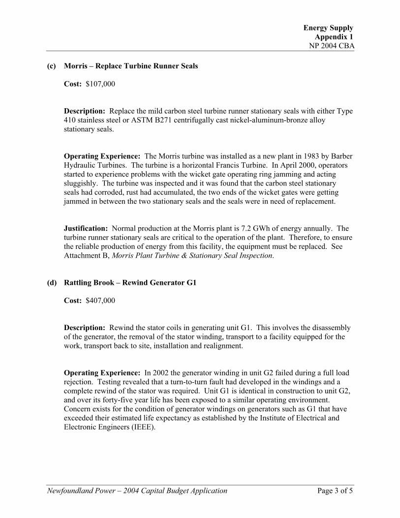
Interposing Relays Over the past five years 26% of all unit trips can been attributed to intermittent loss of the speed reference signal. This is not an unusual situation with electronic controllers employing analog circuitry. When control is provided through a PLC the logic will delay unit trips on loss of speed reference to allow the signal sufficient time to return to normal. Another common problem with the control system is failure of the voltage regulator’s under frequency and over voltage module. In the past these boards have been repaired in house, however integrated circuits and discrete electronic components have become difficult to source. Replacement of the analog voltage regulator with a digital unit will ensure continued support for the system. Pressure Relief Valve As there is no surge tank associated with the penstock, a pressure relief valve (PRV) is required to relieve pressure under full load rejection. A tracking system was designed to preset the pressure relief valve appropriately in the event of a full load rejection on the unit. The tracking system was the result of infield modifications necessary because of a penstock rupture that occurred during acceptance testing of the 1983 turbine generator system supplied by Barber Hydraulic Turbine. Interfacing with the PRV tracking system has increased the PLC hardware requirements of both the programming effort and the necessary
4
processing power of the PLC. To ensure the long term reliability of the system it is felt that integrating the control of the PRV into the PLC ladder logic improves control and protection for both the PRV and the penstock.
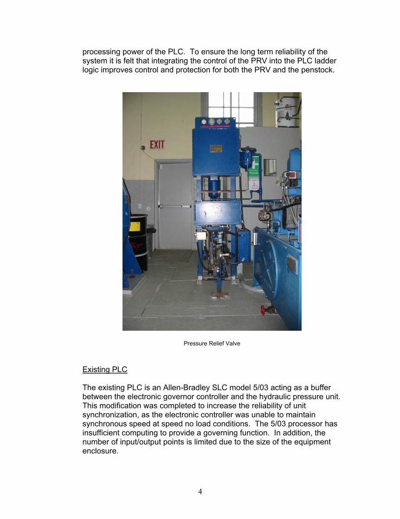
Pressure Relief Valve Existing PLC The existing PLC is an Allen-Bradley SLC model 5/03 acting as a buffer between the electronic governor controller and the hydraulic pressure unit. This modification was completed to increase the reliability of unit synchronization, as the electronic controller was unable to maintain synchronous speed at speed no load conditions. The 5/03 processor has insufficient computing to provide a governing function. In addition, the number of input/output points is limited due to the size of the equipment enclosure.
5
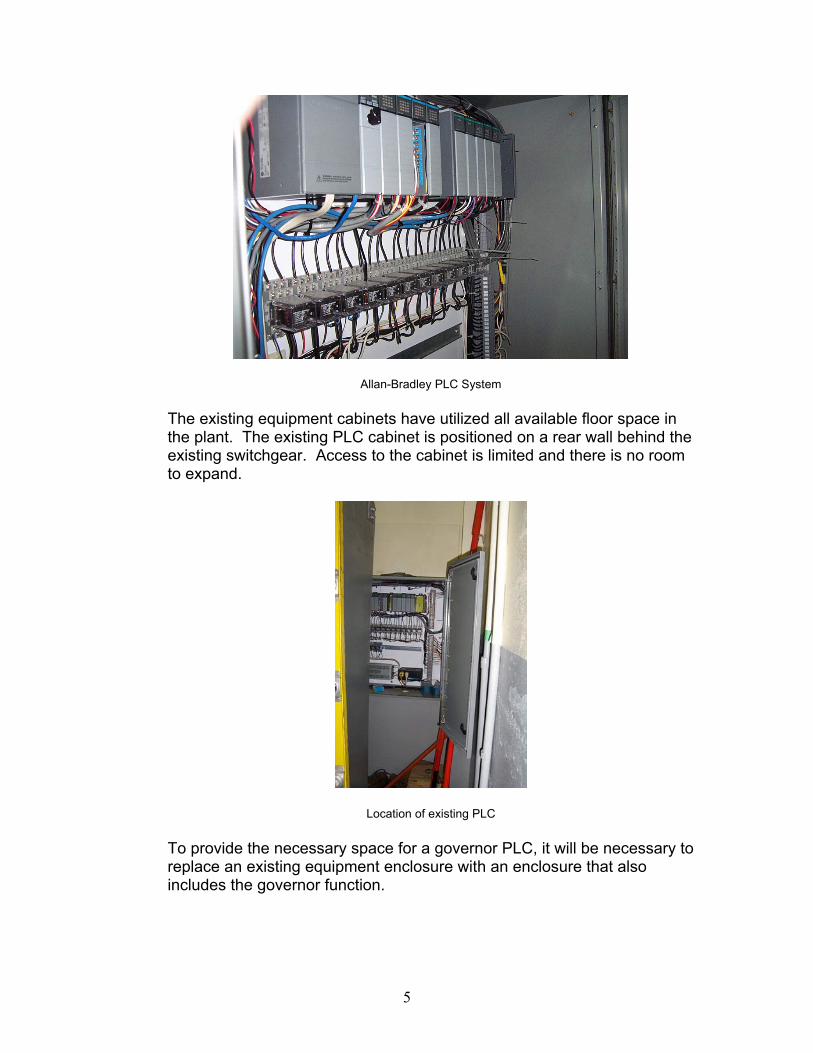
Allan-Bradley PLC System The existing equipment cabinets have utilized all available floor space in the plant. The existing PLC cabinet is positioned on a rear wall behind the existing switchgear. Access to the cabinet is limited and there is no room to expand.
Location of existing PLC To provide the necessary space for a governor PLC, it will be necessary to replace an existing equipment enclosure with an enclosure that also includes the governor function.
6
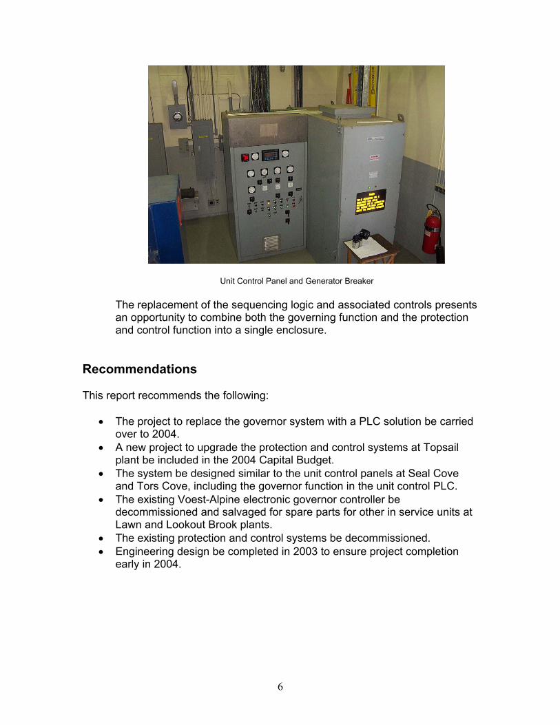
Unit Control Panel and Generator Breaker The replacement of the sequencing logic and associated controls presents an opportunity to combine both the governing function and the protection and control function into a single enclosure.
Recommendations This report recommends the following:
• The project to replace the governor system with a PLC solution be carried over to 2004.
• A new project to upgrade the protection and control systems at Topsail plant be included in the 2004 Capital Budget.
• The system be designed similar to the unit control panels at Seal Cove and Tors Cove, including the governor function in the unit control PLC.
• The existing Voest-Alpine electronic governor controller be decommissioned and salvaged for spare parts for other in service units at Lawn and Lookout Brook plants.
• The existing protection and control systems be decommissioned. • Engineering design be completed in 2003 to ensure project completion
early in 2004.

Appendix A
Topsail Plant Operators’ Log

Energy Supply Appendix 1
Attachment B
Morris Plant Turbine & Stationary Seal Inspection
April 12 2000
1
Turbine Inspection Technical Specifications Size: 1100 kW
Manufacturer: Barber Hydraulic Turbines Date of manufacture: 1983 Serial Number: 1050 Type: Francis
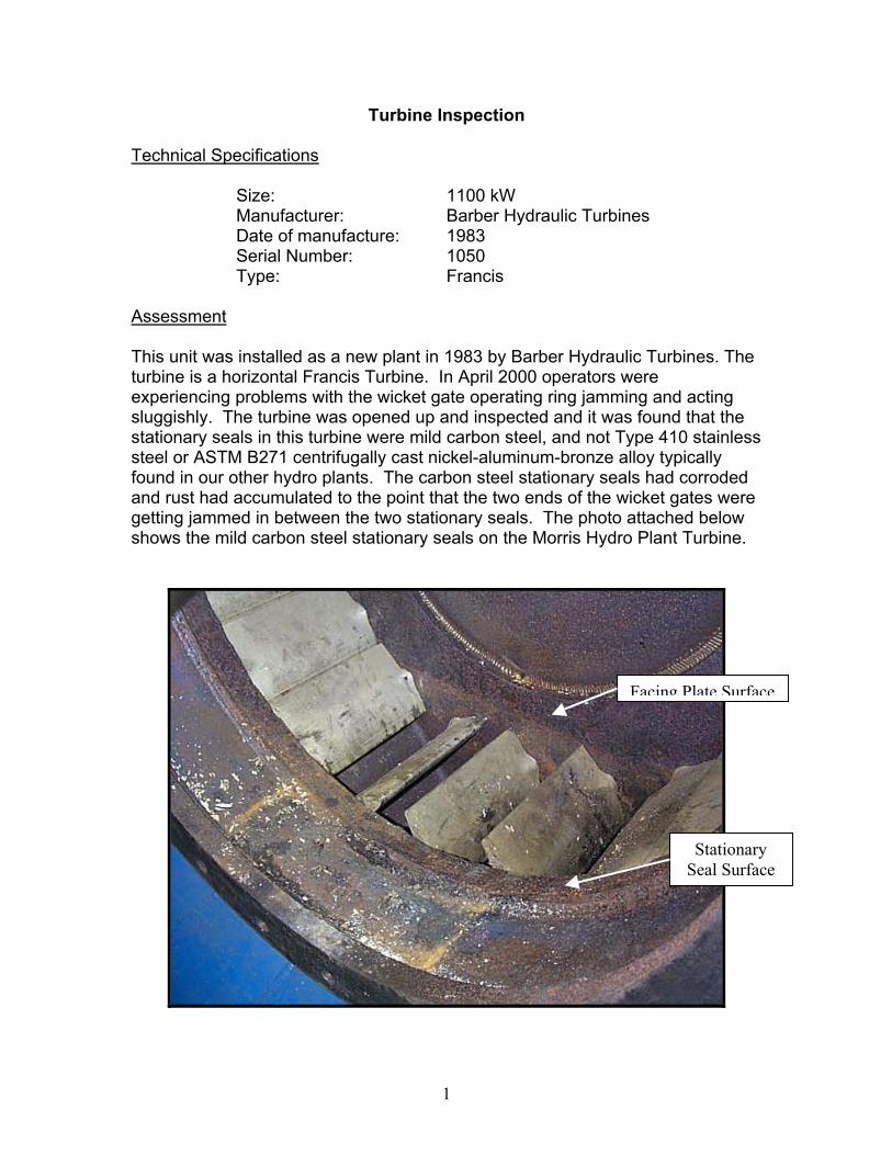
Assessment This unit was installed as a new plant in 1983 by Barber Hydraulic Turbines. The turbine is a horizontal Francis Turbine. In April 2000 operators were experiencing problems with the wicket gate operating ring jamming and acting sluggishly. The turbine was opened up and inspected and it was found that the stationary seals in this turbine were mild carbon steel, and not Type 410 stainless steel or ASTM B271 centrifugally cast nickel-aluminum-bronze alloy typically found in our other hydro plants. The carbon steel stationary seals had corroded and rust had accumulated to the point that the two ends of the wicket gates were getting jammed in between the two stationary seals. The photo attached below shows the mild carbon steel stationary seals on the Morris Hydro Plant Turbine.
Facing Plate Surface
Stationary Seal Surface
2
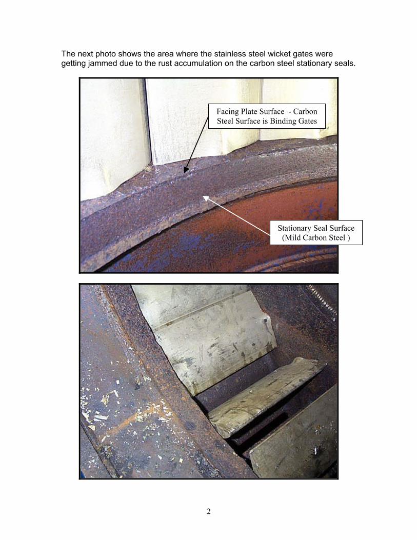
The next photo shows the area where the stainless steel wicket gates were getting jammed due to the rust accumulation on the carbon steel stationary seals.
Stationary Seal Surface (Mild Carbon Steel )
Facing Plate Surface - Carbon Steel Surface is Binding Gates

3
Recommendations The carbon steel stationary seals should be replaced with either Type 410 stainless steel or ASTM B271 centrifugally cast nickel-aluminium-bronze alloy typically found in our other hydro plants.

Energy Supply Appendix 2
NP 2004 CBA
Newfoundland Power – 2004 Capital Budget Application Page 1 of 1
Project Title: New Chelsea Hydro Plant Refurbishment Location: New Chelsea, Trinity Bay Classification: Energy Supply Project Cost: $3,973,000 See Attachment A, “New Chelsea Plant Planned Refurbishment – 2004”, outlining the rationale and justification for this project.
Energy Supply Appendix 2
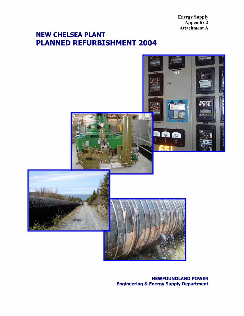
Attachment A NEW CHELSEA PLANT PLANNED REFURBISHMENT 2004
NEWFOUNDLAND POWER Engineering & Energy Supply Department

NEWFOUNDLAND POWER
Engineering & Energy Supply Department
NEW CHELSEA PLANT PLANNED REFURBISHMENT 2004

i
Table of Contents
Page Introduction ........................................................................................................1 Role in Power System........................................................................................1 Scope of Work....................................................................................................2 Electrical Work.........................................................................................2 AC Station Service........................................................................2 DC Distribution and Battery Charger ............................................2 Switchgear and Power Cables .....................................................3 Generator......................................................................................3 Generator Protection and Control .................................................3 Governor.......................................................................................4 Instrumentation .............................................................................5 Bearing Cooling Water Control .....................................................5 Heating and Ventilation.................................................................5 Forebay Water Level Monitoring and Control ...............................5 Mechanical Upgrading.............................................................................6 Turbine..........................................................................................6 Bearing Cooling ............................................................................6 Heating and Ventilation.................................................................6 Civil Work ................................................................................................6 Powerhouse..................................................................................6 Penstock .......................................................................................6 Substation Work ......................................................................................7 Transmission Line Protection........................................................7 Substation Modifications ...............................................................7 Justification ........................................................................................................8 Recommendation ...............................................................................................9 Appendix A Protection and Control Site Assessment Appendix B Turbine Inspection Appendix C Civil Works Site Assessment Appendix D Steel Penstock Assessment Appendix E Feasibility Analysis Appendix F Budget Estimate

1
Introduction On September 24, 1954 the Public Utilities Board required that Newfoundland Power’s predecessor United Towns Electric provide electrical service to the communities of Hant’s Harbour and Old Perlican. As a result, construction began on the New Chelsea Hydroelectric Development. The generating station, with an installed capacity of 3.7 MW, went into service in January 1957 at a construction cost of just over $2.5 million. Two years later the development was expanded when a 0.6 MW generating station was constructed at Pitman’s Pond upstream from New Chelsea. The design of the Pitman’s Pond generating station allowed for remote control from New Chelsea. In 1960, the generating station at Hearts Content was redeveloped, and was also remotely controlled from New Chelsea. Since that time there has been very little in the way of major refurbishment work at New Chelsea, except in 1986, when the three generating stations were automated to provide remote control from the System Control Centre in St. John’s. The control panels, switchgear and protection systems at New Chelsea all date back to the original 1956 installation. In 2004 the major systems in service at New Chelsea will be 48 years old. The expected life of this type of equipment as established by the Institute of Electrical and Electronic Engineers (IEEE) ranges from 25 to 40 years. The existing woodstave and steel penstock has also deteriorated to the extent that replacement is necessary to ensure continued safe and reliable operation. This presents an opportune time to complete refurbishment of other systems at this facility, since replacement of the penstock will result in a five-month period when the plant will be unavailable for operation. Refurbishment of the other plant systems can be completed in this time period, hence avoiding the need for another prolonged plant outage and associated water spillage in future years. The justification for the project is based on a combination of dealing with obsolescence, maintaining public safety, supporting environmental stewardship and ensuring reliable electricity supply from this facility. Role in Power System New Chelsea provides approximately 15.4 GWh of energy on an annual basis, or 4% of total hydroelectric production for Newfoundland Power. In addition, it provides 3.7 MW of power to the Hants Harbour, New Chelsea and Old Perlican areas in the event of a loss of in-feed through transmission line 43L from Hearts Content. The generator also plays a role in maintaining acceptable voltage levels on this long radial transmission system.

2
Scope of Work
The scope of this project includes modifications to the electrical, mechanical and civil works of the plant and the 66 kV substation. The site assessments included in the appendices of this document form the basis of the Scope of Work and the associated budget estimate. The following is a summary of the scope of work:
Electrical Work
AC Station Service
The existing 69,000-volt to 600-volt delta station transformers will be replaced. This secondary voltage is non-standard voltage and there are no spares available for the three single-phase transformers. The potential failure of one or more of these transformers places the operation of the plant at risk. They will be replaced with a 6,900-volt to 120/208 volt, wye, three-phase dry-type transformer located inside the plant in a new switchgear cabinet. In addition, a backup station service will be provided from the substation yard using three standard pole mounted transformers and connected to the switchgear with a manual transfer switch. This will provide a contingency in the event of the failure of the dry-type transformer.
Station Service Transformers
The existing 600-volt delta, 3 phase AC service is non-standard and antiquated with numerous auxiliary panels associated with the distribution system. The system will be modernized and consolidated into a single 120/208 volt three phase panel to provide a standard station service supply. DC Distribution and Battery Charger The DC distribution panel and battery charger will be replaced. The DC distribution is original to the 1956 installation and the battery charger was installed in 1975. Replacement breakers are not available for the DC distribution panel and spare parts are no longer available for the battery charger. The battery bank was replaced in 1996 and is in good condition.

3
Switchgear and Power Cables The existing breaker used to connect and disconnect the generator is located on the high side of the unit transformer resulting in inadequate protection of the generator. The refurbishment will include a new generator breaker installed in conjunction with a digital multifunction protection relay to provide the required generator electrical protection. The switchgear will include new current and potential transformers to replace the units supplied in the 1956 installation. The switchgear will also include a new field breaker, generator neutral grounding reactor, station service transformer and a grounding system for isolating the generator bus for maintenance. The existing breaker and disconnect switch will eventually be replaced with power fuses and an airbreak switch. The existing power cables went into service in March 2000 and remain in good condition. These power cables will be re-terminated in the new switchgear. Modifications to the bus connection between the generator output terminals and the power cables will be required to interface with a new generator breaker. Generator The generator windings are original and have never been rewound. After 48 years in service they have significantly exceeded the average life expectancy of 30 years, which places the reliability of the plant at significant risk, with the potential of six to eight months of downtime and associated spillage of water. The unit will be rewound as part of this project. The excitation system is in good condition, requiring only a general cleaning and replacement of those parts demonstrating excessive wear. The slip rings and commutator will be inspected prior to shutdown, machined and undercut if required. Generator Protection and Control The unit sequencing and control will be implemented using a Programmable Logic Controller (PLC), replacing the numerous discrete relays currently in service. The PLC will be part of our standard Unit Control Panel (UCP) design supplied locally. The UCP will also include a synchronizer, voltage regulator and production metering. The existing generator protection provided through electromechanical relays does not meet the IEEE recommended minimum set of protection for a generator of this size and duty cycle. To meet the standard the following protection will be added using a multifunction digital generator protection relay:
• Loss of excitation • Over-voltage protection • Over-frequency protection • Stator thermal protection
4
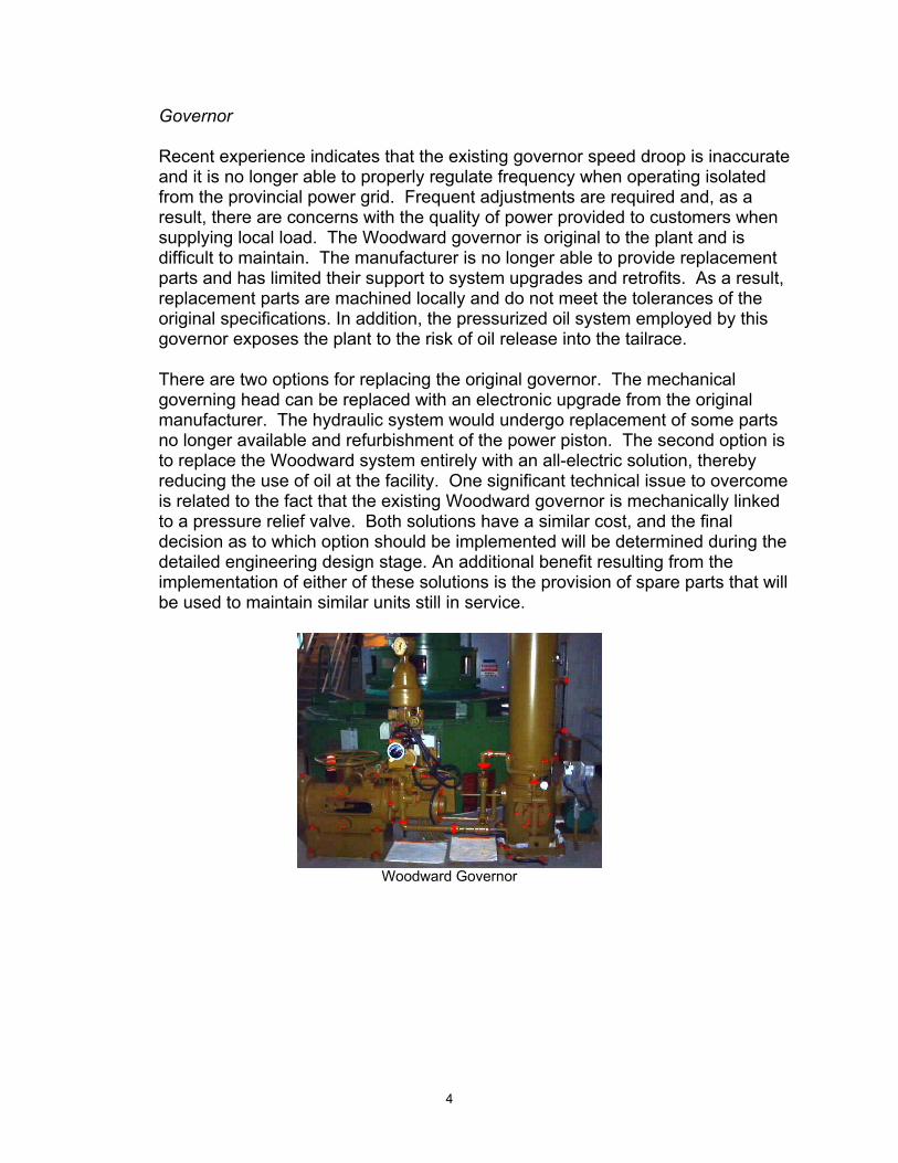
Governor Recent experience indicates that the existing governor speed droop is inaccurate and it is no longer able to properly regulate frequency when operating isolated from the provincial power grid. Frequent adjustments are required and, as a result, there are concerns with the quality of power provided to customers when supplying local load. The Woodward governor is original to the plant and is difficult to maintain. The manufacturer is no longer able to provide replacement parts and has limited their support to system upgrades and retrofits. As a result, replacement parts are machined locally and do not meet the tolerances of the original specifications. In addition, the pressurized oil system employed by this governor exposes the plant to the risk of oil release into the tailrace. There are two options for replacing the original governor. The mechanical governing head can be replaced with an electronic upgrade from the original manufacturer. The hydraulic system would undergo replacement of some parts no longer available and refurbishment of the power piston. The second option is to replace the Woodward system entirely with an all-electric solution, thereby reducing the use of oil at the facility. One significant technical issue to overcome is related to the fact that the existing Woodward governor is mechanically linked to a pressure relief valve. Both solutions have a similar cost, and the final decision as to which option should be implemented will be determined during the detailed engineering design stage. An additional benefit resulting from the implementation of either of these solutions is the provision of spare parts that will be used to maintain similar units still in service.
Woodward Governor

5
Instrumentation The unit does not have stator temperature, vibration or bearing oil level monitoring and protection while the bearing temperature protection is of 1956 vintage and requires upgrading. This protection is recommended for a plant of this size. The instrumentation and protection systems on the generator and turbine will be upgraded to include the following:
• Bearing thermocouples or RTD’s (two per bearing) • Vibration monitoring (one per bearing) • Oil level switches (one per bearing oil pot) • Stator RTD’s (6 10-ohm copper elements) • Incorporate speed switch into UCP
Bearing Cooling Water Control
Automating the valves and flow meter in the bearing cooling water system through the UCP will enhance mechanical protection for the turbine and generator. Cooling will be provided only when required to maintain constant bearing temperature.
Heating and Ventilation The existing manual louver system will be motorized and automated to provide improved temperature regulation. Heating of the plant and generator will be controlled through the UCP. These enhancements will provide heat to the stator when the unit is shut down and cooling air to the plant by opening the building louver and operating the exhaust fan when the building ambient temperature increases. The ability to close the louvers when the unit is not operating will reduce energy loss from the plant. Maintaining a controlled environment within the plant will ensure that problems related to condensation will not lead to electrical failures of the generator and associated equipment. Forebay Water Level Monitoring and Control The existing water level probe and transducer are obsolete, cannot be accurately calibrated and are no longer supported by the manufacturer. The new system (PLC and water level probe) will be interfaced with the UCP as required to provide efficient water management. A detailed assessment of the protection and control is provided in Appendix A.

6
Mechanical Upgrading
Turbine The scroll case vent and 4-way control valve will be replaced with an automatic float type vent, eliminating the need for separate control valves and electrical interface.
The wicket gates will be replaced or refurbished to reduce the potential of sticking and causing undue wear and tear on governor arms and linkages. It will also reduce the run down time on shutdown. The turbine shaft gland seal and shaft sleeve will be inspected and replaced or refurbished as required to prevent water leakage.
Bearing Cooling All bearings will be refurbished as required during the turbine upgrade.
The cooling water system is now fed from two 1 ½” Y type strainers. These will be replaced with a more conventional duplex filter element system. The cooling water system will be replaced or refurbished as required.
Heating and Ventilation
The stationary intake louvers and shutters will be replaced with a motorized louver system. The control for the plant heating and ventilation will be upgraded by incorporating it into the PLC logic control. Concrete repairs to the louver opening & sill plates will also be completed. A detailed assessment of the turbine is found in Appendix B.
Civil Work
Powerhouse Concrete rehabilitation is required in the tailrace area in the vicinity of the water line. The damage is caused by salt-water spray and the freeze thaw cycles experienced in the ocean environment.

7
Penstock
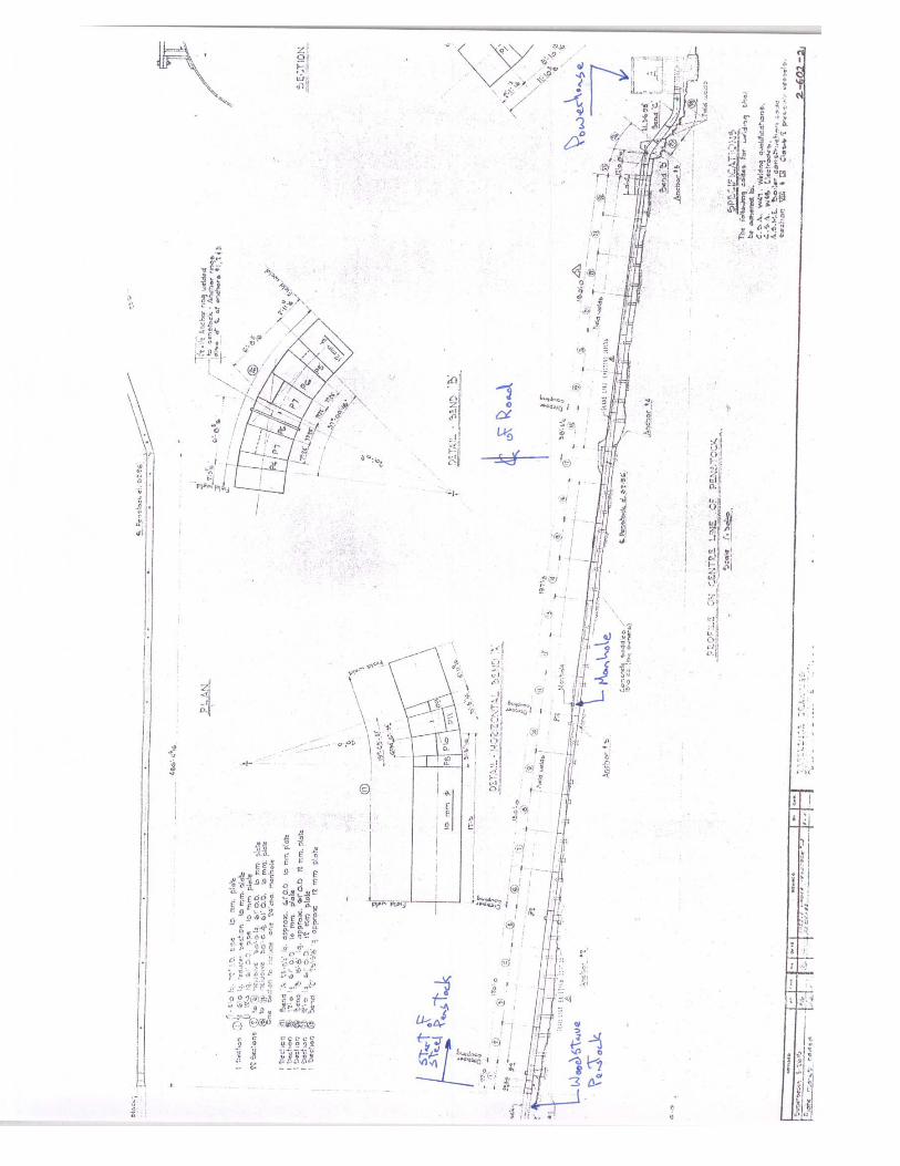
The project involves the replacement of the 867 metres of 1,829 mm diameter woodstave penstock and 240 meters of steel pipeline. The new penstock is to be constructed with steel and dimensioned similar to the existing woodstave penstock. Drainage will be improved near the steel pipeline by installing culverts and porous gravel where required to reduce the risk of corrosion of the pipe.
A detailed assessment of the condition of the penstock is included in Appendix C,
and the internal inspection completed by FGA-CANSPEC consulting engineers in Appendix D.
Substation Work
Transmission Line Protection At present the transmission line protection is spread across the various generator control panels in the plant control room. This is the result of piecemeal protection and control upgrades throughout the life of the plant. The existing generator protection and control panels will be decommissioned to make room for the new Unit Control Panel (UCP). As a result new transmission line protection panels will be required, which will consolidate the various protection elements and greatly simplify the operation, maintenance, testing and troubleshooting of the system.
Substation Modifications The existing transformer breaker (NCH-T2-B) is used to synchronize the generator to the power grid. With the addition of a generator breaker this function will no longer be required. The condition of the breaker is questionable and it will eventually be decommissioned. To accommodate the synchronization of the new generator breaker a potential transformer will be installed on the 66 KV bus. Station service for the substation is provided from the plant station service. This design does not address the situation where station service in the plant is shut down for maintenance. A dedicated substation station service is required to ensure a reliable supply of AC power to the equipment in the substation. The existing transformer T2 protection provided through electromechanical relays consists of a transformer differential (87T), time delayed overcurrent (51N), and instantaneous overcurrent (50). These protection functions, along with others deemed necessary through a general protection review, will be included in a digital transformer and bus protection relay.

8
Justification The project is justified on obsolescence, public safety, environmental stewardship, customer and plant reliability and financial considerations. Examples of each type of justification are provided in this section.
Public Safety The existing woodstave penstock has progressively deteriorated over the 48-year life of the facility. Considerable effort has been made in recent years to contain leaks from the pipeline, and in the past year two major blowouts have had to be repaired. Environmental Stewardship The replacement penstock will be steel and permit the removal of the existing creosote-treated woodstave penstock from the environment. The amount of oil at the facility would be dramatically reduced by the replacement of the hydraulic governor with an all-electric solution, should this alternative be selected. The addition of a water management algorithm in the Unit Control PLC (UCP) will support the efficient use of water resources and reduce the risk of spill. Maintaining hydro production at this plant will reduce the need for burning fossil fuel at Newfoundland Hydro’s Holyrood Generating Station. Reliability Replacing the manufacturer-discontinued and obsolete equipment at the plant with commercially available equipment will reduce the number of equipment failures, and reduce the duration of unscheduled downtime. This will improve customer reliability when the plant is required to supply local generation and plant reliability by increasing availability and maximizing output. Financial
The cost of energy for this plant, including the capital expenses associated with
this and other planned projects, at 3.19 cents per kilowatt hour is substantially less than the cost of energy for new developments such as Rose Blanche, or thermal sources such as Holyrood. A detailed financial analysis is provided in Appendix E.

9
Recommendation Old, deteriorated, high-maintenance equipment places the reliability of the plant at risk and raises concerns regarding potential penstock failure and associated environmental impacts. Newfoundland Power should proceed with this project in 2004. The project will benefit the Company and its customers through improvements in safety, environmental stewardship and reliability. It will reduce the operating and maintenance costs of the plant. Investing in the life extension of facilities such as New Chelsea guarantees the availability of low cost energy to the Province. Otherwise the annual production of 15.4 GWhs would be replaced by more expensive energy sources such as new generation or additional production from the Holyrood thermal generating station.

Appendix A
Protection and Control Site Assessment
NEW CHELSEA REFURBISHMENT PROJECT
SITE ASSESSMENT
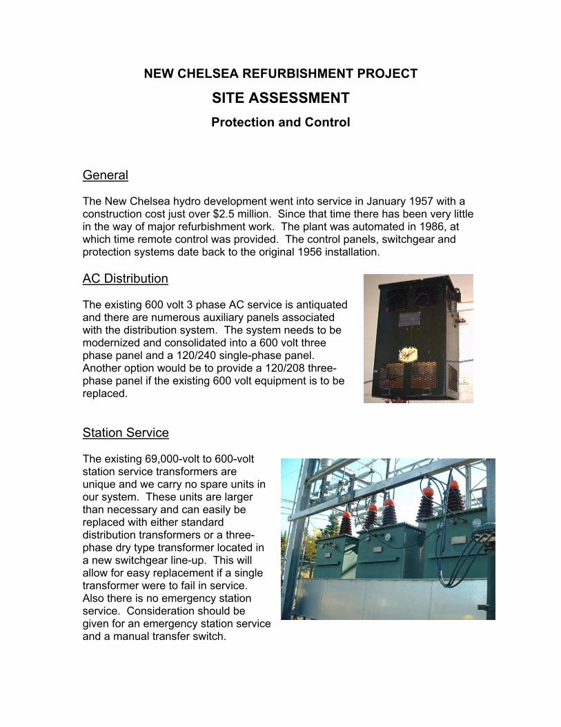
Protection and Control General The New Chelsea hydro development went into service in January 1957 with a construction cost just over $2.5 million. Since that time there has been very little in the way of major refurbishment work. The plant was automated in 1986, at which time remote control was provided. The control panels, switchgear and protection systems date back to the original 1956 installation. AC Distribution The existing 600 volt 3 phase AC service is antiquated and there are numerous auxiliary panels associated with the distribution system. The system needs to be modernized and consolidated into a 600 volt three phase panel and a 120/240 single-phase panel. Another option would be to provide a 120/208 three-phase panel if the existing 600 volt equipment is to be replaced. Station Service The existing 69,000-volt to 600-volt station service transformers are unique and we carry no spare units in our system. These units are larger than necessary and can easily be replaced with either standard distribution transformers or a three-phase dry type transformer located in a new switchgear line-up. This will allow for easy replacement if a single transformer were to fail in service. Also there is no emergency station service. Consideration should be given for an emergency station service and a manual transfer switch.
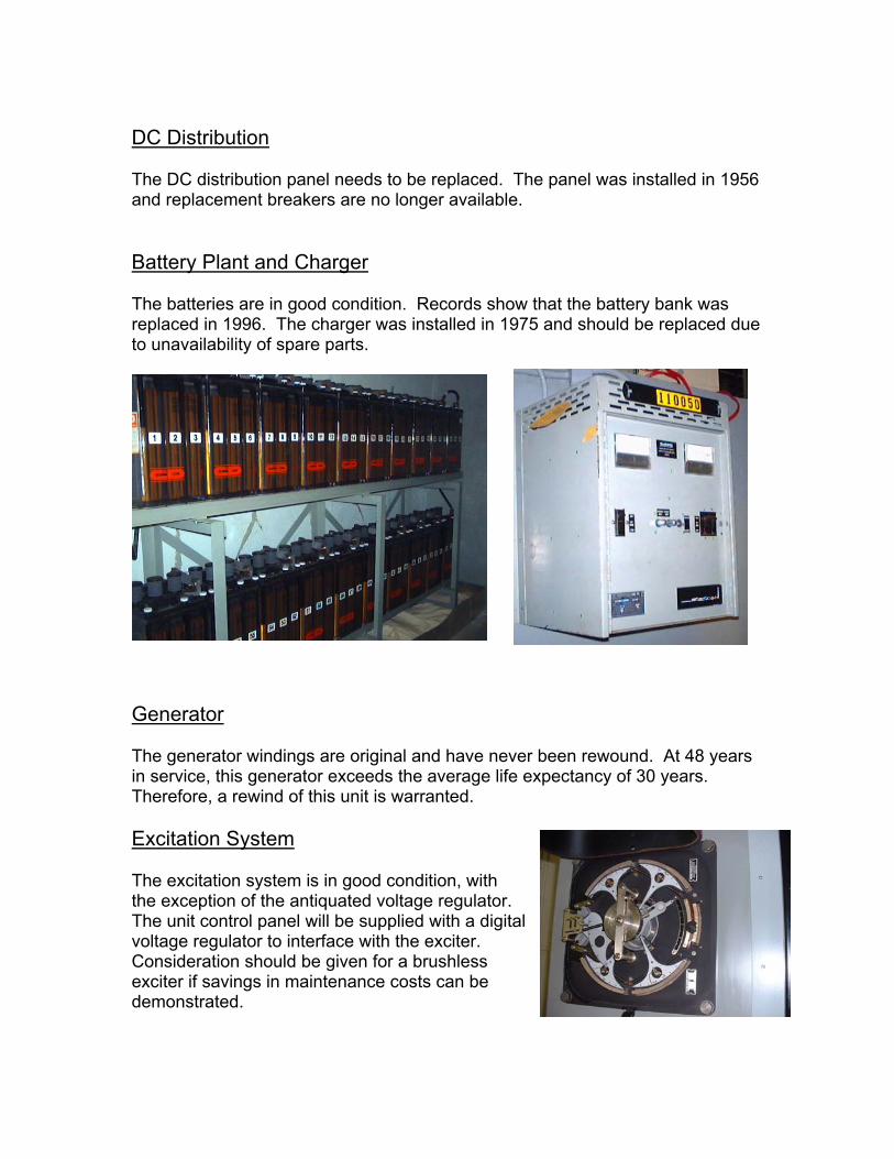
DC Distribution The DC distribution panel needs to be replaced. The panel was installed in 1956 and replacement breakers are no longer available. Battery Plant and Charger The batteries are in good condition. Records show that the battery bank was replaced in 1996. The charger was installed in 1975 and should be replaced due to unavailability of spare parts.
Generator The generator windings are original and have never been rewound. At 48 years in service, this generator exceeds the average life expectancy of 30 years. Therefore, a rewind of this unit is warranted. Excitation System The excitation system is in good condition, with the exception of the antiquated voltage regulator. The unit control panel will be supplied with a digital voltage regulator to interface with the exciter. Consideration should be given for a brushless exciter if savings in maintenance costs can be demonstrated.
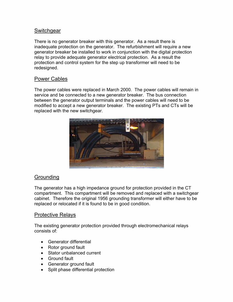
Switchgear There is no generator breaker with this generator. As a result there is inadequate protection on the generator. The refurbishment will require a new generator breaker be installed to work in conjunction with the digital protection relay to provide adequate generator electrical protection. As a result the protection and control system for the step up transformer will need to be redesigned. Power Cables The power cables were replaced in March 2000. The power cables will remain in service and be connected to a new generator breaker. The bus connection between the generator output terminals and the power cables will need to be modified to accept a new generator breaker. The existing PTs and CTs will be replaced with the new switchgear.
Grounding The generator has a high impedance ground for protection provided in the CT compartment. This compartment will be removed and replaced with a switchgear cabinet. Therefore the original 1956 grounding transformer will either have to be replaced or relocated if it is found to be in good condition. Protective Relays The existing generator protection provided through electromechanical relays consists of:
• Generator differential • Rotor ground fault • Stator unbalanced current • Ground fault • Generator ground fault • Split phase differential protection
• Voltage restrained overcurrent The recommended minimum set of protection was provided on this generator, with the exception of the following:
• Loss of excitation • Over-voltage protection • Over-frequency protection • Stator thermal protection
The existing transformer protection provided through electromechanical relays consists of:
• Transformer differential • Time delayed overcurrent • Instantaneous overcurrent
Alarm Annunciation There is little or no annunciation of local plant alarms through the existing control panels. Governor Reports from the local staff indicate that the governor performs acceptably when the generator is parallel with the power system. However, when operating isolated from the grid and supplying local load the governor does a poor job maintaining frequency. The quality of power provided by the generator when supplying isolated local load is below acceptable power quality standards. The existing Woodward governor is mechanically linked to a pressure relief valve. This will impact design solutions for a governor replacement.

Options for governor replacement include a Woodward 505H upgrade (including power piston overhaul) or a new hydraulic replacement, along with the all electric solutions employed recently at Newfoundland Power.
Instrumentation The following protection additions or enhancements to the existing system protection need to be addressed during a system refurbishment:
• Bearing thermocouples or RTDs • Vibration Monitoring • Oil level switches in the bearing pots • Incorporate the six 10-ohm copper RTDs into the unit control PLc • Incorporate speed switch
Bearing Cooling Water Control The existing bearings require water-cooling to ensure safe operating temperatures are maintained. There are valves and piping in place, however there is no automated control of these valves at present. Automating the bearing cooling system will ensure that problems are detected before damage is done to the bearings or shaft, thereby eliminating costly future repairs.

Heating and Ventilation The existing louvers are not controlled. Unit heating and cooling should be incorporated into the unit control PLC. Forebay Water Level Monitoring and Control The existing water level probe and transducer are the older vintage Intertechnology equipment. The equipment is manufacturer discontinued and spare parts are no longer available. This equipment should be replaced with a new 4 to 20-milliamp water level transmitter and interfaced with the unit control PLC.
Associated Work The T2 transformer and transmission line protection for 44L, 43L and 65L is provided by electromechanical relays. The control switches, relays and metering are spread out across the existing plant control panels. To provide sufficient space to install the new protection and control panels, these existing panels will

have to be removed. Therefore, the existing transformer and transmission line protection will have to be addressed as part of this project. It is recommended that the substation design group consider replacement panels using the digital protective relays. Also the existing control panels provide control switches for operating T1-A and T3-A from the plant control room. Control of these switches will have to be included with the T2 transformer protection panel.

Appendix B
Turbine Inspection

New Chelsea Plant Turbine Inspection
Turbine Inspection Technical Specifications Size: 5600 Hp
Manufacturer: Dominion Engineering Turbine Date of manufacture: 1956 Serial Number: 816 Type: Francis
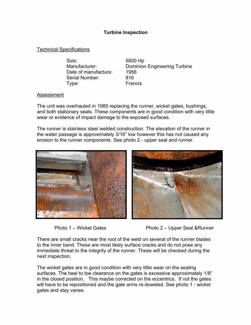
Assessment The unit was overhauled in 1985 replacing the runner, wicket gates, bushings, and both stationary seals. These components are in good condition with very little wear or evidence of impact damage to the exposed surfaces. The runner is stainless steel welded construction. The elevation of the runner in the water passage is approximately 3/16” low however this has not caused any erosion to the runner components. See photo 2 - upper seal and runner.
Photo 1 – Wicket Gates Photo 2 – Upper Seal &Runner
There are small cracks near the root of the weld on several of the runner blades to the inner band. These are most likely surface cracks and do not pose any immediate threat to the integrity of the runner. These will be checked during the next inspection. The wicket gates are in good condition with very little wear on the sealing surfaces. The heel to toe clearance on the gates is excessive approximately 1/8” in the closed position. This maybe corrected on the eccentrics. If not the gates will have to be repositioned and the gate arms re-doweled. See photo 1 - wicket gates and stay vanes.
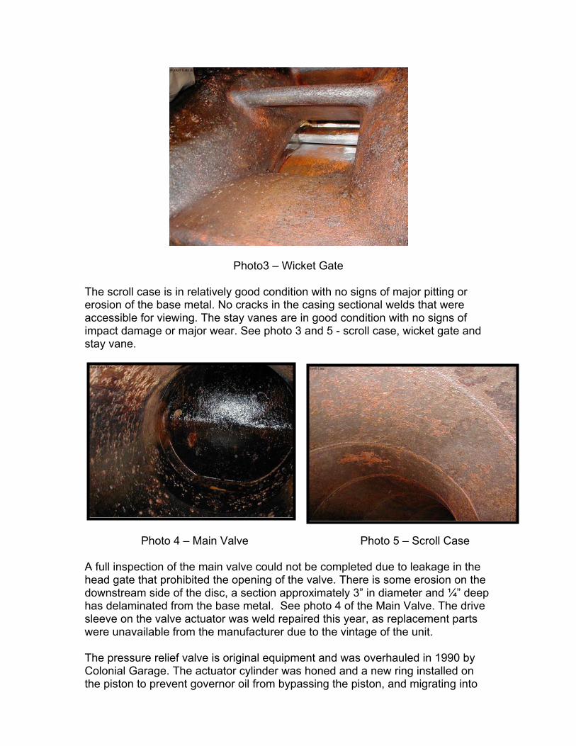
Photo3 – Wicket Gate The scroll case is in relatively good condition with no signs of major pitting or erosion of the base metal. No cracks in the casing sectional welds that were accessible for viewing. The stay vanes are in good condition with no signs of impact damage or major wear. See photo 3 and 5 - scroll case, wicket gate and stay vane.
Photo 4 – Main Valve Photo 5 – Scroll Case
A full inspection of the main valve could not be completed due to leakage in the head gate that prohibited the opening of the valve. There is some erosion on the downstream side of the disc, a section approximately 3” in diameter and ¼” deep has delaminated from the base metal. See photo 4 of the Main Valve. The drive sleeve on the valve actuator was weld repaired this year, as replacement parts were unavailable from the manufacturer due to the vintage of the unit. The pressure relief valve is original equipment and was overhauled in 1990 by Colonial Garage. The actuator cylinder was honed and a new ring installed on the piston to prevent governor oil from bypassing the piston, and migrating into

the dashpot cavity causing the dashpot to overflow. The problem persisted and in 1994 a shutoff solenoid was installed in the oil line from the governor oil system to shutoff the supply oil when the valve fully closed. The governor and control linkages were inspected for worn bushings and lost motion. The cross head on the dump valve connecting arm needs to be re-bushed to reduce the excessive play in the cross head. See photo 6 -Gate operating Arms and Dump valve.
Photo 6 – Gate Operator Arms Photo 7 - Governor
There is a small amount of play in the governor-operating arm. The needle valve in the dashpot on the governor control head is worn and cannot be properly adjusted. See photo 7 - Governor. The manual gate limit adjustment is seized, and this is left at maximum or 100%. The pumping unit is in relatively good condition, with no major oil leaks. The unit maintains proper operating pressure and accumulator air volume. The unit was recently fitted with new pressure switches and oil pump motor.

The air intake louver and exhaust fan are in a poor state of disrepair and will need to be replaced within the next couple of years. See photos below:
Photo 8 – Exhaust Fan Photo 9 – Intake Louver Recommendations The scroll case vent and 4-way control valve needs to be replaced with an automatic float type vent, eliminating the need for separate control valves and electrics. The wicket gates need to be closed up and re-doweled to reduce run down time on shutdown. The stationary intake louvers and shutters need to be replaced with a motorized louver system. The control for the plant heating and ventilation should be incorporated into the PLC logic control for the plant. There are some concrete repairs required to the louver opening & sill plates. The pressure release valve cross head needs to be re-bushed. The remaining linkages and bushings should be inspected when the unit is taken out of service next year. The pressure release valve should be removed and a full internal inspection and any necessary repairs completed when the unit is taken out of service. All the bearings should be removed and inspected during the overhaul. The cooling water system is now fed from two 1 ½” Y type strainers, these should be changed to a more conventional duplex filter element system to permit replacement or cleaning of one filter without removing the unit from service. All cooling water piping and cooling coils to be inspected tested and replaced if required during the overhaul. The upper and lower guide bearing cooling coils were replaced in 1998. The turbine bearing is water-jacketed and should be flushed and tested during the overhaul.

The slip rings and commutator should be inspected prior to shutdown machined and undercut if required. The turbine shaft gland seal and shaft sleeve should be inspected during the overhaul.

Appendix C
Civil Works Site Assessment

NEW CHELSEA REFURBISHMENT PROJECT
SITE ASSESSMENT
Civil Works .
Powerhouse The powerhouse is in good condition. The exterior of the building and roof appear to be satisfactory. Some concrete repairs are required in the tailrace area at the water line. This area is susceptible to salt water spray and numerous freeze thaw cycles.
View of Back of Powerhouse Piers in Tailrace Requiring Repairs Dams The dams are in fairly good shape. The forebay dam requires additional riprap in some areas and the spillway retaining wall at the end of the dam requires some concrete replacement. Penstock The New Chelsea penstock is comprised of 867 m of 1829 mm diameter woodstave and 240 m of 1524 mm diameter welded steel, with the lower 180 m being buried below ground. The New Chelsea penstock has been in service for about 48 years. Based on previous penstock replacements the life of a woodstave penstock is in range the 45 - 50 years. The woodstave section of the New Chelsea penstock is in a similar condition of deterioration as the other woodstave penstocks that have been replaced by Newfoundland Power in the last five years. The life of a buried steel penstock should be greater than 50 years, however, recent inspections of the steel penstock have shown that this is not the case with
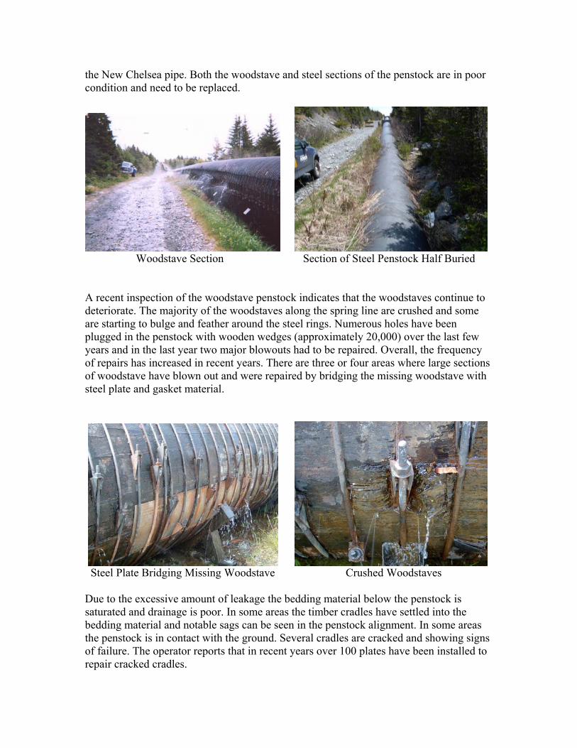
the New Chelsea pipe. Both the woodstave and steel sections of the penstock are in poor condition and need to be replaced.
Woodstave Section Section of Steel Penstock Half Buried A recent inspection of the woodstave penstock indicates that the woodstaves continue to deteriorate. The majority of the woodstaves along the spring line are crushed and some are starting to bulge and feather around the steel rings. Numerous holes have been plugged in the penstock with wooden wedges (approximately 20,000) over the last few years and in the last year two major blowouts had to be repaired. Overall, the frequency of repairs has increased in recent years. There are three or four areas where large sections of woodstave have blown out and were repaired by bridging the missing woodstave with steel plate and gasket material.
Steel Plate Bridging Missing Woodstave Crushed Woodstaves Due to the excessive amount of leakage the bedding material below the penstock is saturated and drainage is poor. In some areas the timber cradles have settled into the bedding material and notable sags can be seen in the penstock alignment. In some areas the penstock is in contact with the ground. Several cradles are cracked and showing signs of failure. The operator reports that in recent years over 100 plates have been installed to repair cracked cradles.

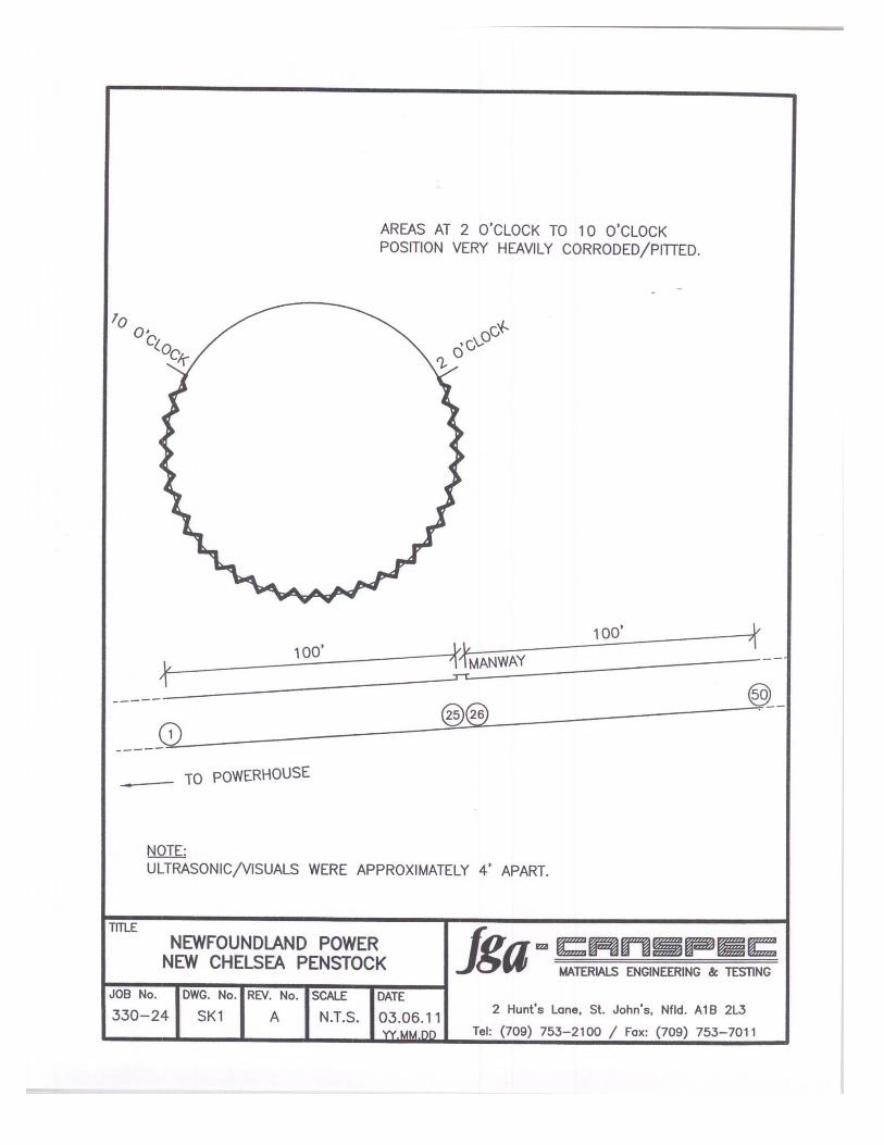
Failed Cradle Penstock in Contact with Ground The exterior section of steel penstock that is above ground is in good condition for the age of the pipe. As the penstock enters the ground it was noted that the soil around the pipe has poor drainage with standing water around the pipe. To assess the condition of the steel penstock an internal and external inspection of the buried pipe was conducted in June 2003 (for inspection results see Memorandum from Gary Murray to Gary Humby dated June 16, 2003). The internal inspection was conducted by FGA-CANSPEC and consisted of visual and ultrasonic testing to determine the wall thickness of the steel penstock. The inspection showed that the inside of the pipe was severely corroded and that the wall thickness is below the design requirement. The external inspection revealed that the pipe is also corroded on the outside, but to a much lesser extent than the inside of the pipe. The external inspection also showed that the backfill material is not free draining and in places the penstock is sitting in saturated backfill. The backfill material is not considered suitable for this type of installation. In conclusion, the woodstave penstock has passed its reliable service life and needs to be replaced. It would have been expected that the steel penstock would be good for another 20-25 years, however, investigations reveal that the steel section has also deteriorated to a condition, where it must be replaced before reliability or failure become an issue. Based on the above the entire penstock should be replaced in the next year.

Appendix D
Steel Penstock Assessment


Appendix E
Feasibility Analysis

June 25, 2003 Memorandum From: Gary L. Murray
To: Gary Humby
Subject: New Chelsea Rehabilitation Projects – Feasibility Analysis File: 401.01.03.23.00 We have completed a feasibility analysis on the continued operation of the New Chelsea hydroelectric development. Several major components of the development are in need of replacement or refurbishment, including the penstock, governor, protection & controls, main inlet valve, and generator. With substantial investment required in the near-term to permit the continued reliable operation of this plant, an economic analysis of this development over a 25-year horizon was warranted. A summary of the costs and benefits associated with this analysis follows. Capital Costs All significant capital expenditures foreseen for the hydroelectric development over the next 25 years have been identified. The majority of these expenditures are currently planned for 2004. The expenditures required to maintain the safe and reliable operation of the facilities are summarized below. A complete breakdown of capital costs and operating costs are provided in Schedule “A”. Cost Year Cost
Description (2004 $) of (Escalated 1.7% Expenditure Per Year) Penstock Replacement - Woodstave $1,735,000 2004 $1,735,600Penstock Replacement - Steel $500,000 2004 $500,000Forebay Dam Rehab $30,000 2004 $30,000Electrical, Protection & Controls $972,000 2004 $972,000Main Inlet Valve Repalcement $150,000 2004 $150,00Refurbish Runner & Wicket Gates $23,000 2004 $23,000Generator Rewind $400,000 2004 $400,000Substation Modifications $163,000 2004 $163,000Intake Concrete Rehab $50,000 2010 $55,300Powerhouse Roof Replacement $50,000 2010 $55,300Spillway Concrete Rehab $30,000 2010 $33,200Transformer Replacement $250,000 2024 $350,200 TOTAL $4,353,000 $4,467,600

The total capital expenditure of all of the projects listed above is $4,353,000 (in 2004 dollar values). All estimates are also shown as escalated values using an assumed escalation rate of 1.7%. Operating Costs Operating costs for this hydroelectric system were based primarily upon recent years’ operating experience. These costs represent both direct charges for operations and maintenance at this plant as well as indirect costs related to activities associated with managing the environment, safety, dam safety inspections, staff training, etc. In addition to inflationary adjustments, operating costs are also increased by $0.50 per horsepower year water usage charges. This fee is paid annually to the Provincial Department of Environment (Water Resources Division) based on yearly hydroplant generation/output. Such a charge is not reflected in the historical annual operating costs for the New Chelsea development. Therefore, an adjustment is applied to account for this operating expense. Penstock maintenance has accounted for a significant portion of the operating costs of this plant in recent years. Future operating cost has been estimated to include an assumed reduction of $5,000 per year to reflect the penstock replacement. Benefits The estimated long-term normal production at this plant under present operating conditions is 15.6 GWh/yr. This estimate is based on the results of the Water Management Study completed by Acres International Limited in December 2000. With an assumed station service adjustment of 0.1 GWh/yr, the normal plant output is estimated at 15.5 GWh/yr. Some of the capital improvement projects will result in decreased energy losses (such as leakage from the woodstave penstock and less head losses in the new steel pipe) and subsequent increases in capacity and generation. The magnitude of these increases is difficult to estimate, but are not significant, so no allowance has been made for any increase in the forecasted generation at New Chelsea. The downtime associated with the 2004 capital works at this plant will result in a higher amount of spill at the forebay compared to a normal operating year. It is anticipated that the potential lost generation may be in the order of 0.5 GWh. Therefore, the analysis assumed production at New Chelsea of 15.0 GWh in 2004, and 15.5 GWh/yr thereafter. Financial Analysis An overall financial analysis of combined costs and benefits has been completed using the levelized cost of energy approach. The levelized cost of energy is representative of the revenue
requirement required to support the combined capital and operating costs associated with the development. The estimated levelized cost of energy from the New Chelsea plant over the next 25 years is 3.19 cents per kWh. This figure includes all projected capital and operating costs necessary to operate and maintain the facility. For comparative purposes the levelized cost was also calculated over 40 years and found to be 3.17 cents per kWh. The levelized cost of energy from New Chelsea can be produced at a lower price than the cost of replacement energy, assumed to come from Hydro’s Holyrood Generating Station. Using Hydro’s short term price forecast and an assumed fuel price escalation rate of 2% in the longer term, incremental energy from the Holyrood Generating Station is estimated to cost 5.53 cents per kWh, levelized over the same 25 year period. Energy from New Chelsea plant also compares favourably with 5.86 cents per kWh (2002 dollars) for the Rose Blanche Brook development and with marginal energy values implied by recent contracts entered into by Hydro with non-utility generators. The future capacity benefits of the continued availability of New Chelsea hydro plant have not been considered in this analysis. In addition, decommissioning costs would be associated with any decision to shut down this facility and the financial benefit associated with the deferral of these costs has not been factored into this analysis. Conclusions It is concluded that operation of the New Chelsea hydroelectric development is economically viable over the long term. Based on the results of this feasibility analysis, it is recommended that the rehabilitation work proposed at New Chelsea for 2004 proceed as planned.

Schedule A Summary of Capital Costs and Operating Costs
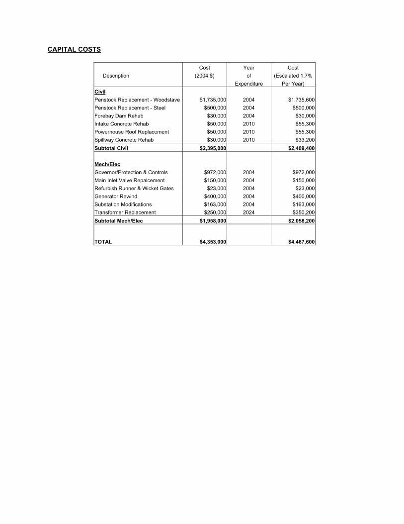
CAPITAL COSTS
Cost Year Cost Description (2004 $) of (Escalated 1.7%
Expenditure Per Year) Civil Penstock Replacement - Woodstave $1,735,000 2004 $1,735,600 Penstock Replacement - Steel $500,000 2004 $500,000 Forebay Dam Rehab $30,000 2004 $30,000 Intake Concrete Rehab $50,000 2010 $55,300 Powerhouse Roof Replacement $50,000 2010 $55,300 Spillway Concrete Rehab $30,000 2010 $33,200 Subtotal Civil $2,395,000 $2,409,400 Mech/Elec Governor/Protection & Controls $972,000 2004 $972,000 Main Inlet Valve Repalcement $150,000 2004 $150,000 Refurbish Runner & Wicket Gates $23,000 2004 $23,000 Generator Rewind $400,000 2004 $400,000 Substation Modifications $163,000 2004 $163,000 Transformer Replacement $250,000 2024 $350,200 Subtotal Mech/Elec $1,958,000 $2,058,200
TOTAL $4,353,000
$4,467,600
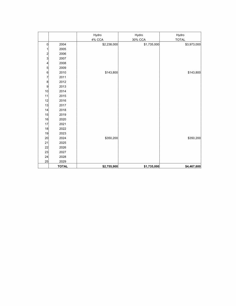
Hydro Hydro Hydro 4% CCA 30% CCA TOTAL
0 2004 $2,238,000 $1,735,000 $3,973,0001 2005 2 2006 3 2007 4 2008 5 2009 6 2010 $143,800 $143,8007 2011 8 2012 9 2013
10 2014 11 2015 12 2016 13 2017 14 2018 15 2019 16 2020 17 2021 18 2022 19 2023 20 2024 $350,200 $350,20021 2025 22 2026 23 2027 24 2028 25 2029
TOTAL $2,755,900 $1,735,000 $4,467,600
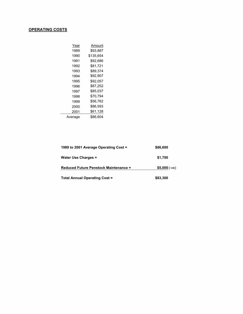
OPERATING COSTS
Year Amount 1989 $93,887 1990 $135,654 1991 $92,686 1992 $81,721 1993 $89,374 1994 $92,907 1995 $92,057 1996 $87,252 1997 $85,037 1998 $70,794 1999 $56,762 2000 $86,593 2001 $61,128
Average $86,604 1989 to 2001 Average Operating Cost = $86,600 Water Use Charges = $1,700 Reduced Future Penstock Maintenance = $5,000 (-ve) Total Annual Operating Cost = $83,300

Appendix F
Budget Estimate

2004 Capital Budget Estimates
Description Cost Estimate
($1,000s) Penstock $ 2,235,000.00 Forebay Dam Rehabilitation $ 30,000.00 Electrical, Protection & Control $ 972,000.00 Main Inlet Valve $ 150,000.00 Refurbish Runner & Wicket Gates $ 23,000.00 Rewind Generator $ 400,000.00 Substation Modifications $ 163,000.00
Total $ 3,973,000.00


![FY 2020 Inpatient Rehabilitation Facility PPS Final Rule ... · Medicare Inpatient Rehabilitation Facility Prospective Payment System for FY 2020 [CMS-1710-F] Summary of Final Rule](https://img.pdfslide.us/doc/110x75/5e152d886e3b54465b2e79a7/fy-2020-inpatient-rehabilitation-facility-pps-final-rule-medicare-inpatient.jpg)