Embed Size (px)
Citation preview

PR
OJ
EC
T S
ITE
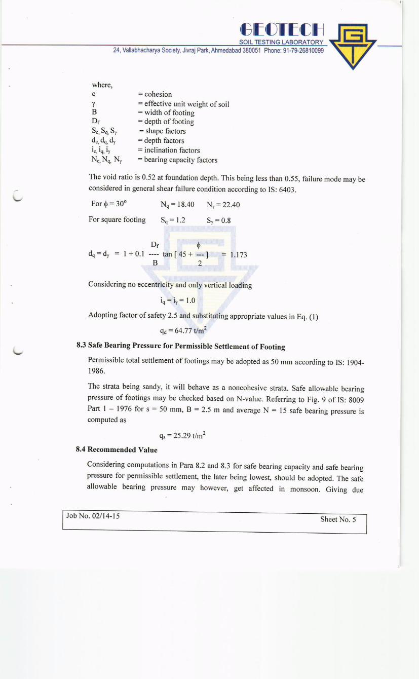
N
WE
S


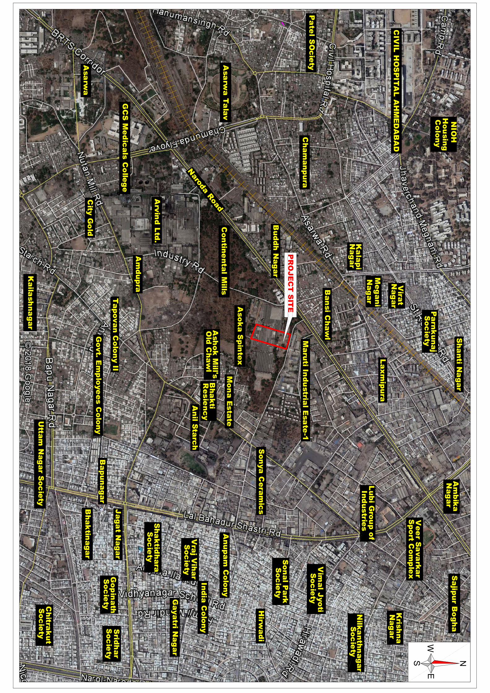
Aso
ka
Sp
inte
x
Ma
ruti In
du
stria
l Esa
te-1
So
nya
Ce
ram
ics
Mo
na
Esta
te
An
il Sta
rch
Ash
ok
Mill's
Old
Ch
aw
lB
ha
kti
Re
sie
nc
y
Co
ntin
en
tal M
ills
Arv
ind
Ltd
.
Asa
rwa
Ta
lav
Ba
nsi C
ha
wl
Bu
dd
h N
ag
ar
Lu
bi G
rou
p o
f In
du
strie
s
Ve
er S
ava
rka
r S
po
rt Co
mp
lex
Am
du
pra
Ta
po
va
n C
olo
ny II
Go
vt. E
mp
loye
es C
olo
ny
City
Go
ld
GC
S M
ed
ica
ls C
olle
ge
Asa
rwa
Ka
ilash
na
ga
r
Utta
m N
ag
ar S
oc
iety
Ch
itrak
ut
So
cie
ty
Go
pin
ath
So
cie
ty
Srid
ha
rS
oc
iety
Bh
ak
tina
ga
r
Ba
pu
na
ga
r
Ja
ga
t Na
ga
r
Sh
ak
tidh
ara
So
cie
ty
Vra
j Vih
ar
So
cie
ty
Ga
ya
tri Na
ga
r
Ind
ia C
olo
ny
An
up
am
Co
lon
y
Hirw
ad
i
So
na
l Pa
rk
Vim
al J
yo
tiS
oc
iety
So
cie
ty
Nilk
an
thn
ag
ar
So
cie
ty
Kris
hn
aN
ag
ar
Sa
jipu
r Bo
gh
aA
mb
ika
Na
ga
r
La
xm
ipu
ra
Sh
an
ti Na
ga
r
Pa
rnk
un
aj
So
cie
ty
Vira
tN
ag
ar
Me
ga
ni
Na
ga
r
Ka
lap
iN
ag
ar
Ch
am
an
pu
ra
CIV
IL H
OS
PIT
AL
AH
ME
DA
BA
D
Ho
usin
g
Co
lon
y
NIO
H
Pa
tel S
Oc
iety
N
WE
S
Naro
da R
oad
PR
OJ
EC
T S
ITE
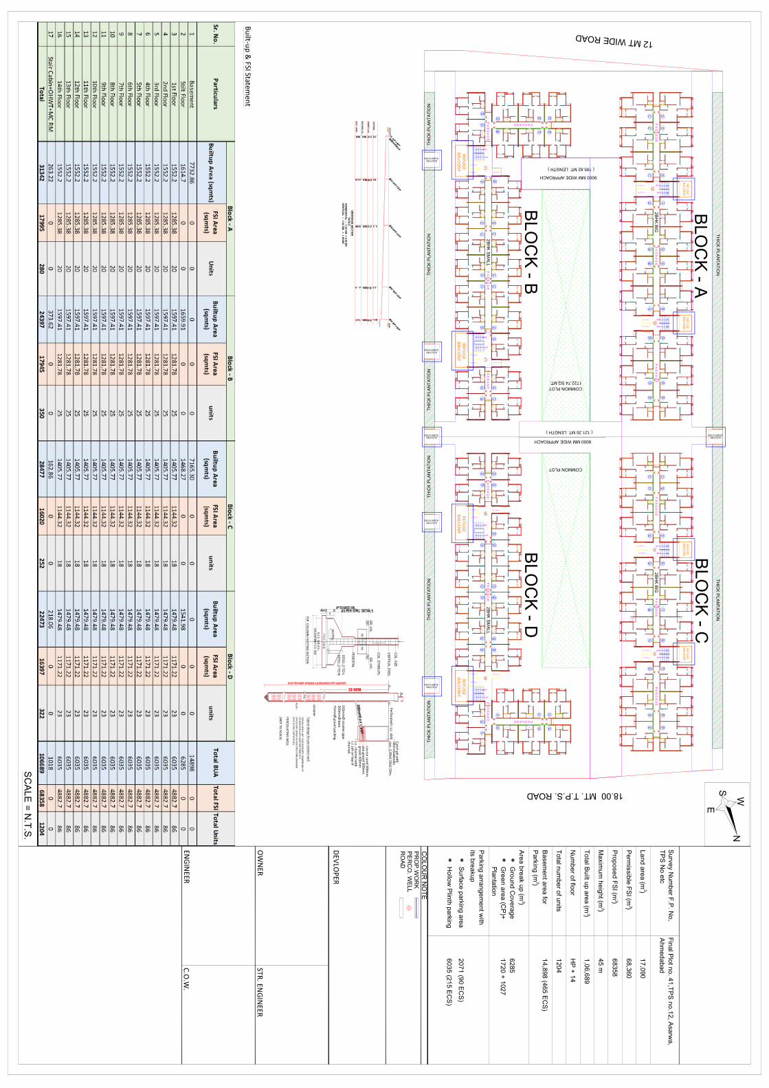
18.00 MT. T.P.S. ROAD
12 MT WIDE ROAD
COMMON PLOT
1722.74 SQ.MT.
COMMON PLOT
9000 MM WIDE APPROACH
9000 MM WIDE APPROACH
TH
ICK
PLA
NT
AT
ION
T
HIC
K P
LA
NT
AT
ION
TH
ICK
PLA
NT
AT
ION
T
HIC
K P
LA
NT
AT
ION
T
HIC
K P
LA
NT
AT
ION
T
HIC
K P
LA
NT
AT
ION
T
HIC
K P
LA
NT
AT
ION
T
HIC
K P
LA
NT
AT
ION
SUBSTATION ELECTRIC
SUBSTATION ELECTRIC
SUBSTATION ELECTRIC
SUBSTATION ELECTRIC
SUBSTATION ELECTRIC
SUBSTATION ELECTRIC
20 PASS. LIFT
13 PASS. LIFT UP
DN
13 PASS. LIFT
13 PASS. LIFT UP
DN
P A
S S
A G
E
P A
S S
A G
E
P A
S S
A G
E
13 PASS. LIFT
13 PASS. LIFT UP
DN
13 PASS. LIFT
13 PASS. LIFTUP
DN
P A
S S
A G
E
P A
S S
A G
E
P A
S S
A G
E
UP
DN
P A
S S
A G
E
P A S S A G E
13 PASS. LIFT
13 PASS. LIFT
13 PASS. LIFT
20 PASS. LIFT
20 PASS. LIFT
13 PASS. LIFT
P A
S S
A G
E
UP
DN
P A
S S
A G
E
2B
HK
SM
ALL
2B
HK
BIG
2B
HK
BIG
UP
DN
P A
S S
A G
E
P A S S A G E
13 PASS. LIFT
13 PASS. LIFT
13 PASS. LIFT
20 PASS. LIFT
20 PASS. LIFT
13 PASS. LIFT
P A
S S
A G
E
UP
DN
P A
S S
A G
E
2B
HK
SM
ALL
12 15
11 16
10 17
08 19
07 20
06 01
05 02
04 03
09 18
13 14
11 14
10 15
09 16
07 18
08 17
12 13
06 01
05 02
04 03
0504
0607
03
08
02
01
23
24
09
22
10
11
21 13
12
25
20
15
14
19
18 17
16
1415
1312
16
11
17
18
20
19
21
10
09
22 07
08
23
05
06
01
02 03
04
( 195.82 MT. LENGTH )
( 121.35 MT. LENGTH )
A
A
B
B
C
C
D
D
REFU
GE
BA
LCO
NY
REFU
GE
BA
LCO
NY
REFU
GE
BA
LCO
NY
REFU
GE
BA
LCO
NY
REFU
GE
BA
LCO
NY
REFU
GE
BA
LCO
NY
REFU
GE
BA
LCO
NY
REFU
GE
BA
LCO
NY
BLO
CK
- A
BLO
CK
- B
BLO
CK
- C
BLO
CK
- D
SC
ALE
= N
.T.S
. NW
E
S
ENG
INEER
STR. EN
GIN
EERO
WN
ER
C.O
.W.
DEV
LOP
ER
TP
S N
o e
tc
Su
rvey N
um
be
r F.P
. No
,
Ah
med
aba
d
Fin
al P
lot n
o. 4
1,T
PS
no
.12
, Asarw
a,
17
,090
La
nd
are
a (m
) 2
68
,360
Pe
rmis
sib
le F
SI (m
)
68
35
8P
rop
ose
d F
SI (m
)
45
mM
axim
um
he
ight (m
)
1,0
6,6
89
To
tal B
uilt u
p a
rea (m
)
HP
+ 1
4N
um
be
r of flo
or
12
04
To
tal n
um
be
r of u
nits
14
,89
8 (4
65
EC
S)
Ba
se
men
t are
a fo
r
Pa
rkin
g (m
)
62
85
Are
a b
rea
k u
p (m
)
Gro
un
d C
ove
rage
17
20
+ 1
02
7G
ree
n a
rea (C
P)+
20
71
(90
EC
S)
Pa
rking
arra
ng
em
en
t with
Su
rface
pa
rking
are
a
its b
rea
kup
2
2
2
2
2
2
CO
LO
UR
NO
TE
PR
OP
.WO
RK
RO
AD
PE
RC
O. W
ELL
60
35
(21
5 E
CS
)H
ollo
w P
linth
pa
rkin
g
Pla
nta
tion
Bu
ilt-up
& FSI Statem
ent
HO
RIZ
ON
TA
L :- 1
.00 C
M. =
4.0
0 M
T.
VE
RT
ICA
L :- 1
.00 C
M. =
1.0
0 M
T.
DR
AIN
AG
E S
EC
TIO
N
SC
AL
E
INV
ER
T L
VL.
GR
OU
ND
LV
L.
DIS
T. IN
MT.
CU
TT
ING
LE
VE
L
TO
MU
NI M
AN
HO
LE
GR
OU
ND
STEEL // TO B
GR
. LVL.
CO
L. STIRR
UPS
CO
L. SIZE
VER
TICA
L STEEL
STEEL // TO L
P.C
.C. 1:4::8
AS
/ST
RU
R.C
.C. S
IZE B X L
EXC
AV
AT
ION
/P.C
.C. S
IZE
TYP. C
OLU
MN
FOO
TING
SECTIO
N
PE
DESTA
L
PB
PB
GR
. LVL.
STRU
CT
UR
E DES
IGN
AS
PER
STR
UCTU
RAL EN
GIN
EER
TO 4
00
0.0
0SQ
.MTS
.AN
D P
ART TH
ERE OF IT.
FOR
BU
ILDIN
G U
NIT
15
00
.00
SQ.M
TS. OR M
ORE A
ND
UP
Typ
ical design
for p
erco
lation
well
NO
TE:-
(TH
IS IS O
NLY SK
ETCH P
LAN
)
75
mm
Ø gravel p
acking
strain
er
15
0m
mØ
strain
er pip
e3
00
mm
Ø b
ore
G.L.
air ven
t
G.L.
Perfo
rated
r.c.c. slab
cou
rse san
d 30
0mm
.p
ea g
ravel 3
00
mm
.g
ravel 3
00
mm
c.c. cha
nn
el with
c.i. jali on
top of
cha
nn
el.
filterationm
edia
size:-2.0
0x2
.50
x2.5
0m
.
Catch
pit w
ith
PER
CO
LATIN
G W
ELL
(NO
T TO SC
ALE)
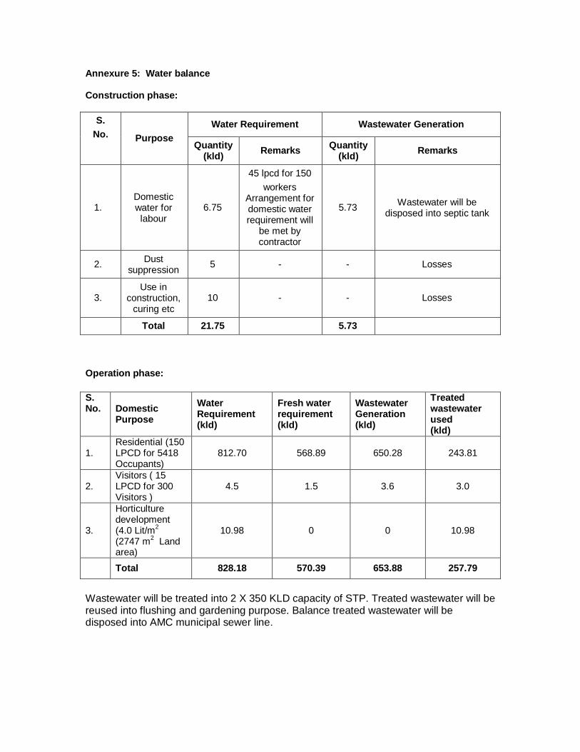
Annexure 5: Water balance Construction phase:
S. No. Purpose
Water Requirement Wastewater Generation
Quantity (kld) Remarks Quantity
(kld) Remarks
1. Domestic water for labour
6.75
45 lpcd for 150 workers
Arrangement for domestic water requirement will
be met by contractor
5.73 Wastewater will be disposed into septic tank
2. Dust suppression 5 - - Losses
3. Use in
construction, curing etc
10 - - Losses
Total 21.75 5.73 Operation phase: S. No. Domestic
Purpose Water Requirement (kld)
Fresh water requirement (kld)
Wastewater Generation (kld)
Treated wastewater used (kld)
1. Residential (150 LPCD for 5418 Occupants)
812.70 568.89 650.28 243.81
2. Visitors ( 15 LPCD for 300 Visitors )
4.5 1.5 3.6 3.0
3.
Horticulture development (4.0 Lit/m2 (2747 m2 Land area)
10.98 0 0 10.98
Total 828.18 570.39 653.88 257.79
Wastewater will be treated into 2 X 350 KLD capacity of STP. Treated wastewater will be reused into flushing and gardening purpose. Balance treated wastewater will be disposed into AMC municipal sewer line.
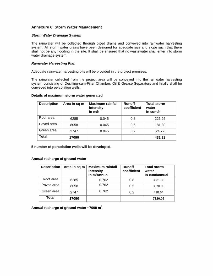
Annexure 6: Storm Water Management Storm Water Drainage System The rainwater will be collected through piped drains and conveyed into rainwater harvesting system. All storm water drains have been designed for adequate size and slope such that there shall not be any flooding in the site. It shall be ensured that no wastewater shall enter into storm water drainage system. Rainwater Harvesting Plan Adequate rainwater harvesting pits will be provided in the project premises. The rainwater collected from the project area will be conveyed into the rainwater harvesting system consisting of Desilting-cum-Filter Chamber, Oil & Grease Separators and finally shall be conveyed into percolation wells. Details of maximum storm water generated
Description Area in sq m Maximum rainfall intensity In m/h
Runoff coefficient
Total storm water In cum/h
Roof area 6285 0.045 0.8 226.26 Paved area 8058 0.045 0.5 181.30 Green area 2747 0.045 0.2 24.72 Total 17090 432.28
5 number of percolation wells will be developed. Annual recharge of ground water
Description Area in sq m Maximum rainfall intensity In m/Annual
Runoff coefficient
Total storm water In cum/annual
Roof area 6285 0.762 0.8 3831.33 Paved area 8058 0.762 0.5 3070.09 Green area 2747 0.762 0.2 418.64
Total 17090 7320.06
Annual recharge of ground water ~7000 m3
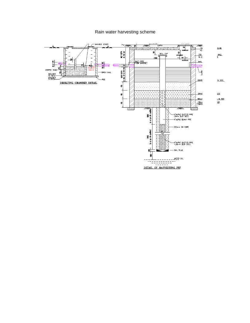
Rain water harvesting scheme
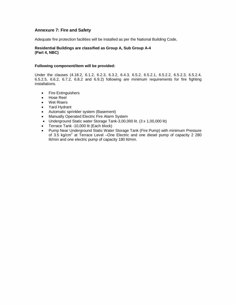
Annexure 7: Fire and Safety Adequate fire protection facilities will be installed as per the National Building Code, Residential Buildings are classified as Group A, Sub Group A-4 (Part 4, NBC)
Following component/item will be provided: Under the clauses (4.18.2, 6.1.2, 6.2.3, 6.3.2, 6.4.3, 6.5.2, 6.5.2.1, 6.5.2.2, 6.5.2.3, 6.5.2.4, 6.5.2.5, 6.6.2, 6.7.2, 6.8.2 and 6.9.2) following are minimum requirements for fire fighting installations.
Fire Extinguishers Hose Reel Wet Risers Yard Hydrant Automatic sprinkler system (Basement) Manually Operated Electric Fire Alarm System Underground Static water Storage Tank-3,00,000 lit. (3 x 1,00,000 lit) Terrace Tank -10,000 lit (Each block) Pump Near Underground Static Water Storage Tank (Fire Pump) with minimum Pressure
of 3.5 kg/cm2 at Terrace Level –One Electric and one diesel pump of capacity 2 280 lit/min and one electric pump of capacity 180 lit/min.
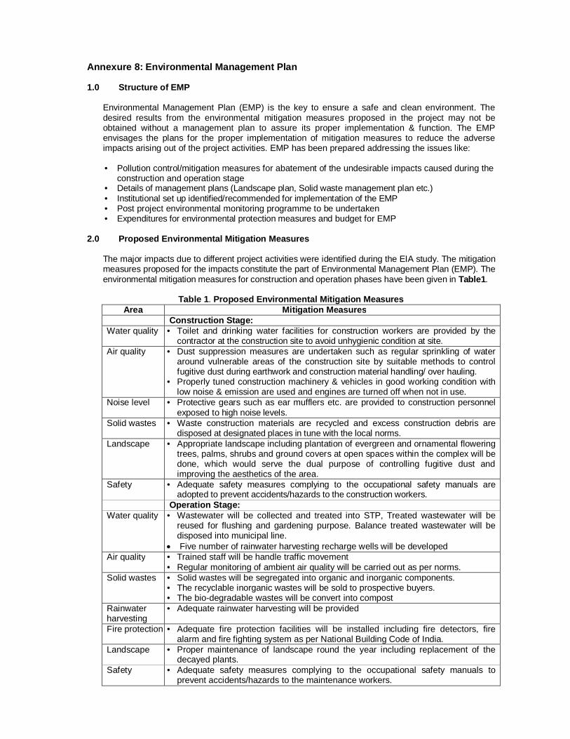
Annexure 8: Environmental Management Plan 1.0 Structure of EMP
Environmental Management Plan (EMP) is the key to ensure a safe and clean environment. The desired results from the environmental mitigation measures proposed in the project may not be obtained without a management plan to assure its proper implementation & function. The EMP envisages the plans for the proper implementation of mitigation measures to reduce the adverse impacts arising out of the project activities. EMP has been prepared addressing the issues like:
• Pollution control/mitigation measures for abatement of the undesirable impacts caused during the
construction and operation stage • Details of management plans (Landscape plan, Solid waste management plan etc.) • Institutional set up identified/recommended for implementation of the EMP • Post project environmental monitoring programme to be undertaken • Expenditures for environmental protection measures and budget for EMP
2.0 Proposed Environmental Mitigation Measures
The major impacts due to different project activities were identified during the EIA study. The mitigation measures proposed for the impacts constitute the part of Environmental Management Plan (EMP). The environmental mitigation measures for construction and operation phases have been given in Table1.
Table 1. Proposed Environmental Mitigation Measures
Area Mitigation Measures Construction Stage: Water quality • Toilet and drinking water facilities for construction workers are provided by the
contractor at the construction site to avoid unhygienic condition at site. Air quality • Dust suppression measures are undertaken such as regular sprinkling of water
around vulnerable areas of the construction site by suitable methods to control fugitive dust during earthwork and construction material handling/ over hauling.
• Properly tuned construction machinery & vehicles in good working condition with low noise & emission are used and engines are turned off when not in use.
Noise level • Protective gears such as ear mufflers etc. are provided to construction personnel exposed to high noise levels.
Solid wastes • Waste construction materials are recycled and excess construction debris are disposed at designated places in tune with the local norms.
Landscape • Appropriate landscape including plantation of evergreen and ornamental flowering trees, palms, shrubs and ground covers at open spaces within the complex will be done, which would serve the dual purpose of controlling fugitive dust and improving the aesthetics of the area.
Safety • Adequate safety measures complying to the occupational safety manuals are adopted to prevent accidents/hazards to the construction workers.
Operation Stage: Water quality • Wastewater will be collected and treated into STP, Treated wastewater will be
reused for flushing and gardening purpose. Balance treated wastewater will be disposed into municipal line.
Five number of rainwater harvesting recharge wells will be developed Air quality • Trained staff will be handle traffic movement
• Regular monitoring of ambient air quality will be carried out as per norms. Solid wastes • Solid wastes will be segregated into organic and inorganic components.
• The recyclable inorganic wastes will be sold to prospective buyers. • The bio-degradable wastes will be convert into compost
Rainwater harvesting
• Adequate rainwater harvesting will be provided
Fire protection • Adequate fire protection facilities will be installed including fire detectors, fire alarm and fire fighting system as per National Building Code of India.
Landscape • Proper maintenance of landscape round the year including replacement of the decayed plants.
Safety • Adequate safety measures complying to the occupational safety manuals to prevent accidents/hazards to the maintenance workers.

Others • The building will be provided with disabled-friendly design, timber-free construction, energy efficient lighting & ventilation, and control of indoor environment.
3.0 Environmental Monitoring Plan
It is imperative that the Project Authority set up regular monitoring stations to assess the quality of the surrounding environment after the commissioning of the project. An environmental monitoring programme is important as it provides useful information and helps to: • Verify the predictions on environmental impacts presented in this study, • Assist in detecting the development of any unwanted environmental situation, and thus, provides
opportunities for adopting appropriate control measures, and • Evaluate the performance and effectiveness of mitigation measures proposed in the EMP and
suggest improvements in management plan, if required, • Satisfy the legal and statutory obligations. The post project monitoring plan including areas, number and location of monitoring stations, frequency of sampling and parameters to be covered is summarized in Table 2. The monitoring will be the responsibility of EMC.
Table 2: Environmental Monitoring Plan Source Monitoring Location Parameters to be
Monitored Frequency
Ambient Air Quality At 3 locations (1 inside the complex and 2 outside in surrounding 1 km zone along predominant wind directions)
PM10, PM2.5, SO2, NOxOnce in a season and as per requirement of SPCB
Ambient Noise At 3 locations (1 inside the complex and 2 outside in surrounding 100 m zone)
Day and night equivalent noise level
Once in a season and as per requirement of SPCB
Stack Stack PM, SO2, NOx, CO Once in a season and as per requirement of SPCB
The post operational monitoring schedule will be under the supervision of the Site Engineer at the project site. Monitoring will be carried out by recognized laboratories.
4.0 Environment Management Cell An Environment Management Cell (EMC) will be responsible for implementation of the post project-monitoring plan for this project. The composition of the Environment Management Cell and responsibilities of its various members are given in Table 3.
Table 3. Environment Management Cell
S. No. Designation Proposed responsibility
1. Chairman of Society Overall responsibility for environment management and decision making for all environmental issues
2. Secretary Hires a Consultant and fulfills all legal Requirements as per MOEF/GPCB/CPCB
3. Supervisor Ensure environmental monitoring as per appropriate procedures

5.0 Environmental Budget
A capital cost provision of about Rs. 80 lakh has been kept in the project cost towards the environmental protection, control & mitigation measures and implementation of the EMP. The budgetary cost estimate for the EMP is given in Table 4.
Table 4 Environmental Budget
S.
No. Head Approximate
recurring cost per annum (Rs.
in lacs)
Approximate Capital cost (Rs. In lacs)
Basis for cost estimates
1. Air 1.0 2.5 Stack and DG room
2. Water 3.0 60.0 Cost of STP
3. Solid and hazardous
waste management
2.5 4.0 Provide bins door to door and transportation cost
4. Environment monitoring
3.5 0 The recurring cost would be incurred on hiring of consult-ants and payment of various statutory fees to regulatory
agencies. 5. Rain water 2.0 9 Collection system, treatment
and recharge well 6. Green belt 2.0 4.5 -
Total 14 80
6.0 General Principles in Greenbelt Design Plants grown in such a way so as to function as pollutant sinks are collectively referred as greenbelt. These plants should also provide an aesthetic backdrop for persons using the site and for the surrounding community. General principles in greenbelt design considered for this study are:
Type of pollution (air, noise, water and land pollution) likely from the activities at the site
Semi arid zone and sub-zone where the greenbelt is located (and hence the plant species which can be planted in the area).
Water quantity and quality available in the area
Soil quality in the area
Greenbelt is designed to minimize the predicted levels of the possible air and noise pollutants. While designing the scheme the following facilities are considered:
Site perimeter and approach road
Along the internal roads
In and around the building area
To ensure a permanent green shield around the periphery planting is recommended in two phases.
In the first phase one row of evergreen and fast growing trees (which grows up to 10-15m) with maturity period of around three years shall be planted at 3.0 meter interval along with fast growing ground covers to enhance the water holding capacity, improve the organic content and check the soil erosion.
In the second phase after eighteen months, second row of trees with large leaf surface area with large ever green canopy and longer life span shall be planted at 6.0 meters intervals.
6.1 Greenbelt Design for Site The selection of the trees is based on their phenology (thus road side trees will not have leaf fall during summer and rainy seasons when shade is most needed). Trees with more litter fall have been avoided.
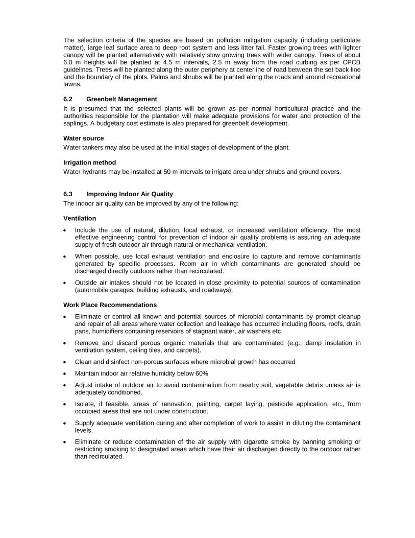
The selection criteria of the species are based on pollution mitigation capacity (including particulate matter), large leaf surface area to deep root system and less litter fall. Faster growing trees with lighter canopy will be planted alternatively with relatively slow growing trees with wider canopy. Trees of about 6.0 m heights will be planted at 4.5 m intervals, 2.5 m away from the road curbing as per CPCB guidelines. Trees will be planted along the outer periphery at centerline of road between the set back line and the boundary of the plots. Palms and shrubs will be planted along the roads and around recreational lawns.
6.2 Greenbelt Management It is presumed that the selected plants will be grown as per normal horticultural practice and the authorities responsible for the plantation will make adequate provisions for water and protection of the saplings. A budgetary cost estimate is also prepared for greenbelt development.
Water source Water tankers may also be used at the initial stages of development of the plant.
Irrigation method Water hydrants may be installed at 50 m intervals to irrigate area under shrubs and ground covers.
6.3 Improving Indoor Air Quality The indoor air quality can be improved by any of the following:
Ventilation
Include the use of natural, dilution, local exhaust, or increased ventilation efficiency. The most effective engineering control for prevention of indoor air quality problems is assuring an adequate supply of fresh outdoor air through natural or mechanical ventilation.
When possible, use local exhaust ventilation and enclosure to capture and remove contaminants generated by specific processes. Room air in which contaminants are generated should be discharged directly outdoors rather than recirculated.
Outside air intakes should not be located in close proximity to potential sources of contamination (automobile garages, building exhausts, and roadways).
Work Place Recommendations
Eliminate or control all known and potential sources of microbial contaminants by prompt cleanup and repair of all areas where water collection and leakage has occurred including floors, roofs, drain pans, humidifiers containing reservoirs of stagnant water, air washers etc.
Remove and discard porous organic materials that are contaminated (e.g., damp insulation in ventilation system, ceiling tiles, and carpets).
Clean and disinfect non-porous surfaces where microbial growth has occurred
Maintain indoor air relative humidity below 60%
Adjust intake of outdoor air to avoid contamination from nearby soil, vegetable debris unless air is adequately conditioned.
Isolate, if feasible, areas of renovation, painting, carpet laying, pesticide application, etc., from occupied areas that are not under construction.
Supply adequate ventilation during and after completion of work to assist in diluting the contaminant levels.
Eliminate or reduce contamination of the air supply with cigarette smoke by banning smoking or restricting smoking to designated areas which have their air discharged directly to the outdoor rather than recirculated.

6.4 Safety Aspects of the Project The following needs to be implemented:
Fall Protection
The Contractor is required to provide fall protection to employees who are working at heights equal to or greater than 1.8 m. fall protection can be in the form of perimeter protection such as guardrails and toe rails, personal protective equipment (PPE), a safety monitoring system, or a fall protection plan. Activities that require personal fall protection systems include steel erection bolting, riveting, fitting-up and plumbing-up, work over water and some deep excavation work.
On buildings or structures not adaptable to temporary floors, and where scaffolds are not used, safety nets will be installed and maintained whenever the potential fall distance exceeds two storey.
The PPE standard should cover occupational foot, head, hearing, and eye protection.
Foot Protection: If machines or operations present the potential for foot injury, the Contractor must provide foot protection, which is of safe design and construction for the work to be performed. Workers and visitors should not be allowed on a construction site without safety boots.
Head Protection: If head hazards remain after all steps have been taken to control them (safety nets for work at heights, proper housekeeping), the Contractor must provide employees with appropriate head protection.
Noise Protection: Workers should be wearing hearing protection devices (ear plugs, ear muffs, canal caps) that are in good condition whenever they are involved in noisy activities.
Eye Protection: When machines or operations present potential eye injury from physical or chemical elements, the Contractor must select, provide, maintain and required affected employees to use appropriate eye protection. Eye protection (safety glasses and goggles, face shields and welding helmets) must be adequate and reasonably comfortable.
To the greatest extent possible, working surfaces must be kept dry to prevent slips and falls and to reduce the chance of nuisance odors from pooled water.
All equipment and materials should be stored in designated storage areas that are labeled as such.
Ladders and Stairs
The Contractor is required to inspect and maintain all ladders and temporary/portable steps to ensure that they are in good working condition.
Portable ladders used for access to an upper landing surface must extend a minimum of 1.8 m above the landing surface, or where not practical, be provided with grab rails and be secured against movement while in use.
All ladders must be used only on stable and level surfaces unless secured to prevent accidental movement. Ladders must not be used on slippery surfaces unless secured or provided with slip-resistant feet to prevent accidental movement.
The Contractor should provide a ladder (or stairway) at all work points of access where there is a break in elevation of 0.5 m or more.
When there is only one point of access between levels, it must be kept clear to permit free passage by workers. If free passage becomes restricted, a second point of access must be provided and used. At all times, at least one point of access must be kept clear.
All required stairway and ladder fall protection systems must be provided and installed before employees begin work that requires them to use stairways or ladders.
Scaffolds
Access to Scaffolds - access to and between scaffold platforms more than 0.6 m above or below the point of access will be made by portable/attachable ladders or ramps.
Employees must never use makeshift devices, such as boxes and barrels, to increase the scaffold platform working level height.
Trenching and Excavation
The area around the trench/excavation would be kept clear of surface encumbrances.
Water should not be allowed to accumulate in the excavation.
Adjacent structures would be shored in accordance with the design documents to prevent collapse.
Guardrails or some other means of protecting people from falling into the trench/excavation would be present.
The trench or excavation would be shored or sloped to prevent cave-ins.
Electrical Safety
If work has to be done near an overhead power line, the line must be de-energized and grounded before work is started.
A licensed electrician would have completed all temporary wiring and electrical installations required for construction activities.
Fuses and circuit breakers would be used to protect motherboards, conductors and equipment.
Extension cords for equipment or as part of a temporary wiring system will not be damaged or compromised in any way and insulation must be of the highest grade.
Anytime electrical equipment is deactivated for repair, or circuits are shut off, the equipment will be locked out and tagged at the point where it can be energized.
Temporary lights may not be suspended by their cords.
The Contractor would provide the necessary safety equipment, supplies and monitoring equipment to their personnel.
Cranes A competent person has been designated to supervise activities that require the use of cranes. Cranes would not be operated near any power lines. All picks would be carefully planned to ensure that the crane adequately hoist the load. The hoisting signals would be posted on the exterior of the crane.
Occupational Noise Exposure
The Contractor should implement engineering controls to reduce noise levels.
The Contractor should provide hearing protection to employees that are exposed to noise levels above the permissible limit.
Welding and Cutting
The Contractor's employees would be trained in hot work procedures.
There should be adequate ventilation to reduce the build up of metal fume.
The hot work operators would use proper personal protective equipment (i.e., welding helmet, burning goggles, face shield, welding gloves, and apron).
There would be a fire extinguisher present at all welding and burning activities.
Extinguishers would also be placed at locations where slag and sparks may fall.
Oxygen and flammable gas bottles are separated by at least 7 m when not in use.
The Contractor would control the release of gases, vapors, fumes, dusts, and mists with engineering controls (e.g., adequate ventilation).
General Guidelines
Signs and symbols would be visible during any construction activity that presents a hazard. Upon completion of such activity, the postings must be removed immediately.
The Contractor would post specific DANGER signs when an immediate hazard exists and specific CAUTION signs when the potential for a hazard exists. EXIT, NOTICE and specific safety signs may also be posted in the work area.
Signage for traffic control, including directional signs, is applicable when the Contractor is disrupting traffic along a public way.
Danger signs are posted at all immediate hazards (i.e. Danger: Open Hole).
Caution signs are posted at all potential hazards (i.e. Caution: Construction Area, Caution: Buried Cable).
The floor that is being used as the erection floor must be solidly planked or decked over its entire surface except for access openings.
Every floor, working place and passageway would be kept free from protruding nails, splinters, holes or loose boards.
Combustible scrap and debris (wood, clearing/grubbing material) would be removed from the site daily or should be securely stored in covered containers.
The Contractor would have a spill prevention control and countermeasure plan that limits the risk of releases of oil or hazardous materials to the environment.