Embed Size (px)
Citation preview

,D-A163 561 VHF FM COMMUNICATIONS ANTENNAS FOR PROJECT SINCOAlRS 1/2
(UH I TAIL WHIP AND C (U) ARMY AVIATION SYSTEMSCOMMAND ST LOUIS MO J CARALYUS ET AL DEC 85
UNCLASSIFIED USAAVSCOM-TR-85-E-3 F/G i7/2 t N1EEEEEEEEElhiEEEEEEEEEllEEEIEhEEEEEEEEE|hIEhEEEEEEE-EEE|EhEEEEEEEEE|hIEhEEEEEEEEEEEEEEEEElhElhEEEE

1111 f 2.8 12.5I l lL 3 2i ll'j I. J 14 IIII
l~ii .._.' ____20_
II - 1111"--= II
MICr. OCOPY RESOLUTION TEST CHART
PCATIOqAL BUREAU OF STANDARDS - .963 -1.
-~ -~'~ - J .,-,
.6°

*\
AVSCOM
Technical Report-85-E-3
(0Lf) VHF-FM COMMUNICATIONS ANTENNAS FOR PROJECT SINCGARS( (UH-1 TAIL WHIP AND CABIN ROOF BENT WHIP EVALUATION)
S JOSEPH CARALYUS
I JOSEPH MILLER
S CARLOS GRATACOS
0FRANK CANSLER
US ARMY AVIONICS R&D ACTIVITY
I "DECEMBER 1985
DISTRIBUTION STATEMENT
*' I Approved for public release;I- distribution is unlimited.
S~ 0- •DTICP* LECTE
---. 3
Research and Development Technical Report-• Aviation Systems Command
.'

SNOTI CES
Disclaimers
The citation of trade names and names of manufacturers inthis report is not to be construed as official Governmentindorsement or approval of commercial products or servicesreferenced herein.
Destruction Notice
Destroy this report when it is no longer needed. Do notreturn it to the originator.
For classified documents, follow the procedures in DoD5200.22-M, Industrial Security Manual, Section 11-19, orDoD 5200.1-R, Information Security Program Regulation,Chapter IX. For unclassified, limited documents, destroyby any method that will prevent disclosure of contentsor reconstruction of the document.
"&" 1 Availbllty Cales
.
-I
I N

UNCLASSIFIED /(
SECURITY CLASSI ICATION OF THIlS PAGE
REPORT DOCUMENTATION PAGEIa. REPORT SECURITY CLASSIFICATION lb. RESTRICTIVE MARKINGS
UNCLASSI FIED2a. SECURITY CLASSIFICATION AUTHORITY I DISTRIBUTION/AVAILABILITY OF REPORT
Approved for public release; distributionZb. DECLASSIFICATION /OOWNGRAOING SCH4EDULE is unl imi ted.
4. PERFORMING ORGANIZATION REPORT NUMBER(S) S. MONITORING ORGANIZATION REPORT NUMBER(S)
AVSCOM TR-85-E-3
6a. NAME OF PERFORMING ORGANIZATION 6b. OFFICE SYMBOL 7a. NAME OF MONITORING ORGANIZATION
U.S. Army Aviation Systems Cmd (fapplicabe) U.S. Army Aviation Systems Command (AVSCOM)Avionics R&D Activity (AVRADA)i SAVAA-C
6c. ADDRESS (City, State, and ZIP Code) 7b. ADDRESS (City, State, and ZIP Code)
ATTN: SAVAA-C ATTN: AMSAV-WZFort Monmouth, NJ 07703-5401 4300 Goodfellow BoulevardSt. Louis, MO 63120-1798
Ba. NAME OF FUNDING ISPONSORING 8b. OFFICE SYMBOL 9. PROCUREMENT INSTRUMENT IDENTIFICATION NUMBERORGANIZATION (if applicable)
8c. ADDRESS (City State. and ZIP Code) 10. SOURCE OF FUNDING NUMBERS
PROGRAM PROJECT TASK WORK UNITELEMENT NO. NO. NO. ACCESSION NO.
II. TITLE (Include Security Classification)VHF-FM COMMUNICATIONS ANTENNAS FOR PROJECT SINCGARS (UH-I TAIL WHIP AND CABIN ROOFBENT WHIP EVALUATION)
1Z PSR.CINAL AUTHOR(S)
I Joseph Caralyus, Joseph Miller, Carlos Gratacos. Frank Cansler13a. TYPE OF REPORT 13b. TIME COVERED 14. DATE OF REPORT (Year, Month, Day) 15. PAGE COUNT
Technical Report I FROM _ TO _ 1985 December 10316. SUPPLEMENTARY NOTATION
17 COSATI CODES 18. SUBJECT TERMS (Continue on reverse if necessary and identify by block number)
FIELD GROUP SUB-GROUP UH-l Helicopter Straight Whip Antenna VSWRRadiation Patterns Gain Antenna
1nsBent Whip Antenna Impedance19. ABSTRACT (Continue on reverse if necessar and identify by block number)The American Electronics Laboratory (AEL), Allaire, NJ, was tasked by the U.S. Army AvionicsResearch and Development Laboratory (SAVAA-M), Fort Monmouth, NJ, to develop replacementbreadband matching modules for the CU-942B and the FM 10-30-1 antenna to satisfy specifiedrequirements for Project SINCGARS. AEL was further tasked to test various candidate an-tennas provided by commercial vendors that are mechanically interchangeable with theCU-942B and the FM lO-30-1.--After completion of the AEL development/test program, AVRADA tasked an independent, non-
based Government antenna test facility to conduct prescribed antenna verification tests inaccordance with an agreed upon test plan.
This technical report describes communications antenna systems provided by Dayton-Granger,Inc (DGI), American Electronics Lab (AEL), and Avionics Antenna Systems (AVANT). The test- ..
(CONTINUED)20 DISTRIBUTIONI AVAILABILITY OFABSTRACT 121. ABSTRACT SECURITY CLASSIFICATION
OUNCLASSIFIEDAJNLIMITEO 0 SAME AS RPT. QOTIC USERS UNCLASSIFIED22a. NME PF RESPONSIBLE INDIVIDUAL 22b TELEPHONE (Include Area Code) 22c. OFFICE SYMBOL
FranR Cansler (AV) 995-2901 SAVAA-CO FORM 1473, 84 MAR 83 APR editon may be used untI exhausted SECURITY CLASSIFICATION OF THIS PAGE
All other editions are obsoleteUNCLASSIFIED
I . % " " . " , ."'. . % % "' ' ' " . . ' .- " " .- ' .' - -, . ' . - - ' . " . • " . " , "' ' , ', ' ..

%UNCLASSIFIED
SICURITY CLASSIFICATION OF THIS PAGE
19. ABSTRACT (contd)
measurements were conducted at the Naval Air Development Center, Antenna Test Facility lo-cated in Warminster, PA. -,
*AJ
The information in this report provides, in part, the technical data for the protection datapackage of adequate VHF-FM Communications antennas for the UH-l helicopter when used withthe new SINCGARS Radio.
N/
% . ',. -,U N C L A S S I F I E D
-.. .
SECUIlTY CL.ASIFICATION OF THIS PAGE
%

TABLE OF CONTENTS
Page
Section
1. TEST OBJECTIVE 1
2. TEST ITEMS 1
3. SPECIFICATIONS 1
4. TEST FACILITY 2
, 5. TEST CONFIGURATION 2
6. TEST PROCEDURE 10
7. DATA PRESENTATION 11
8. SUMMARY 23
Appendices
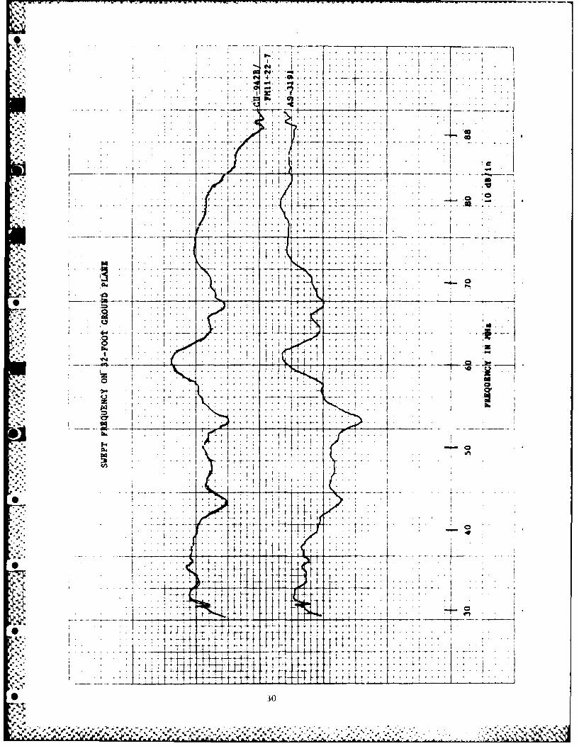
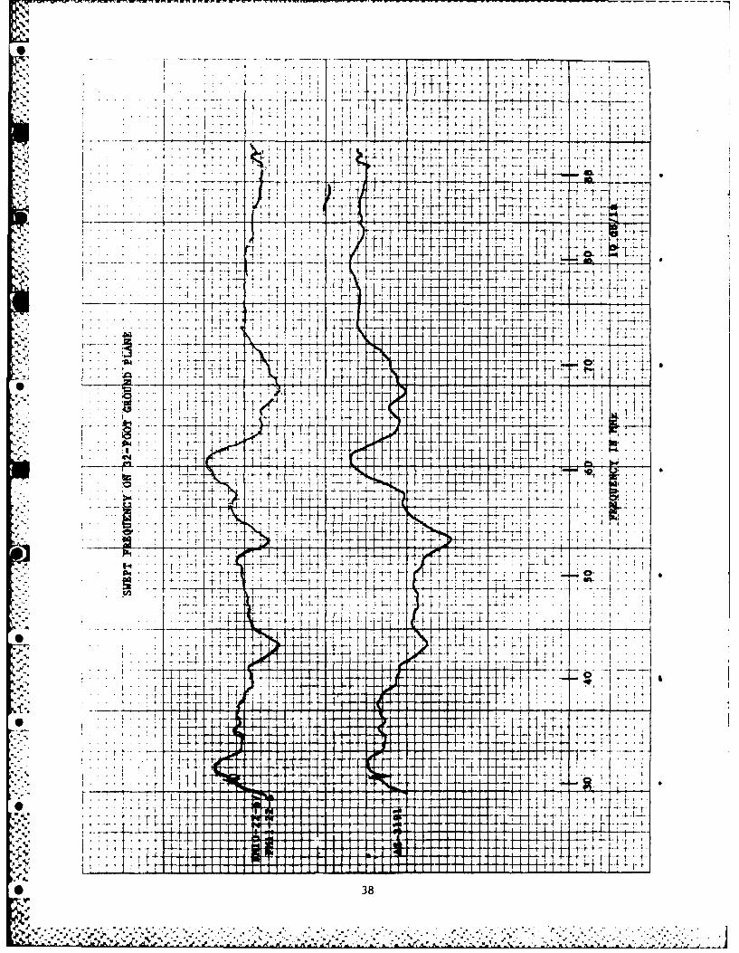
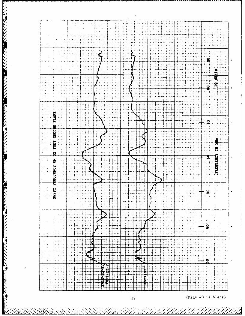
A. SWEPT FREQUENCY PATTERNS - 32-FOOT GROUND PLANE 27
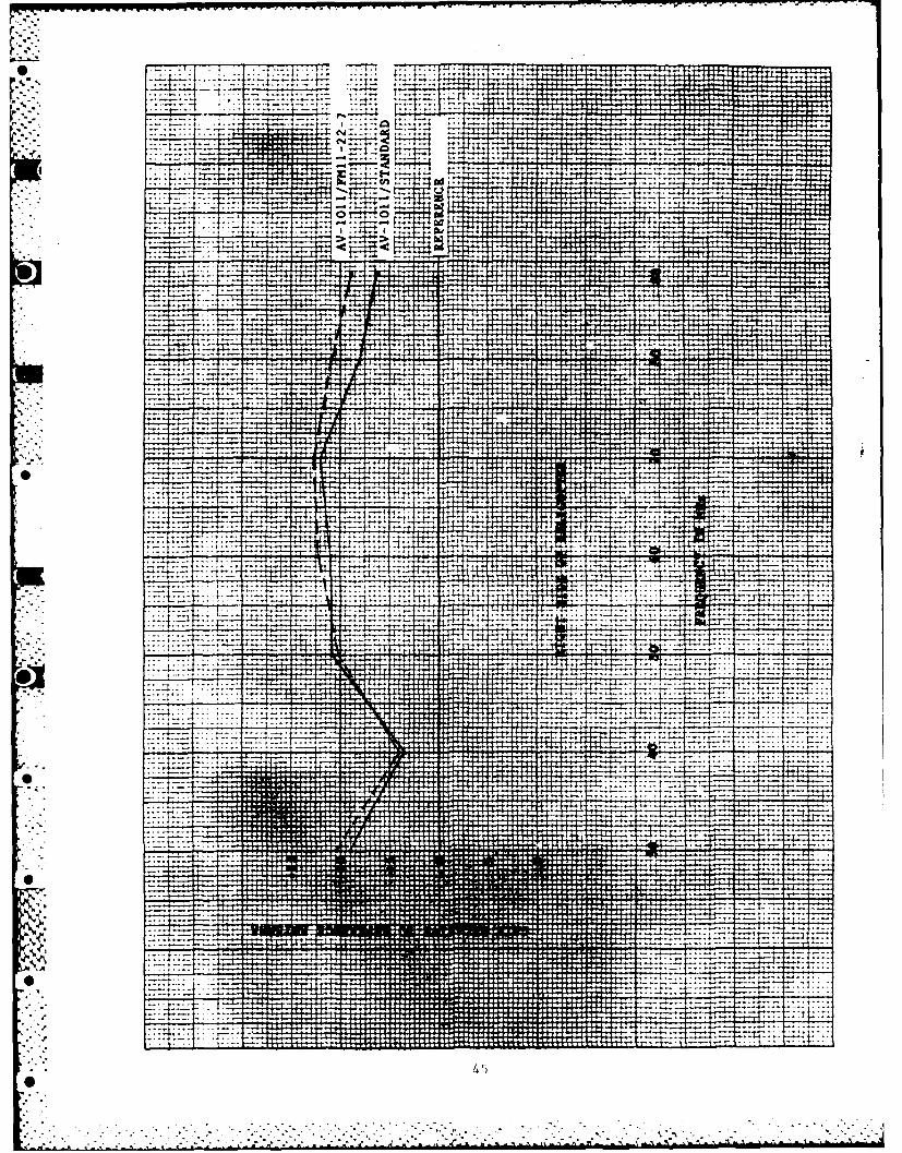
B. GAIN PLOTS - RIGHT SIDE OF HELICOPTER 41
C. GAIN PLOTS - FRONT OF HELICOPTER 51
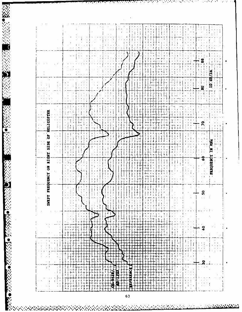
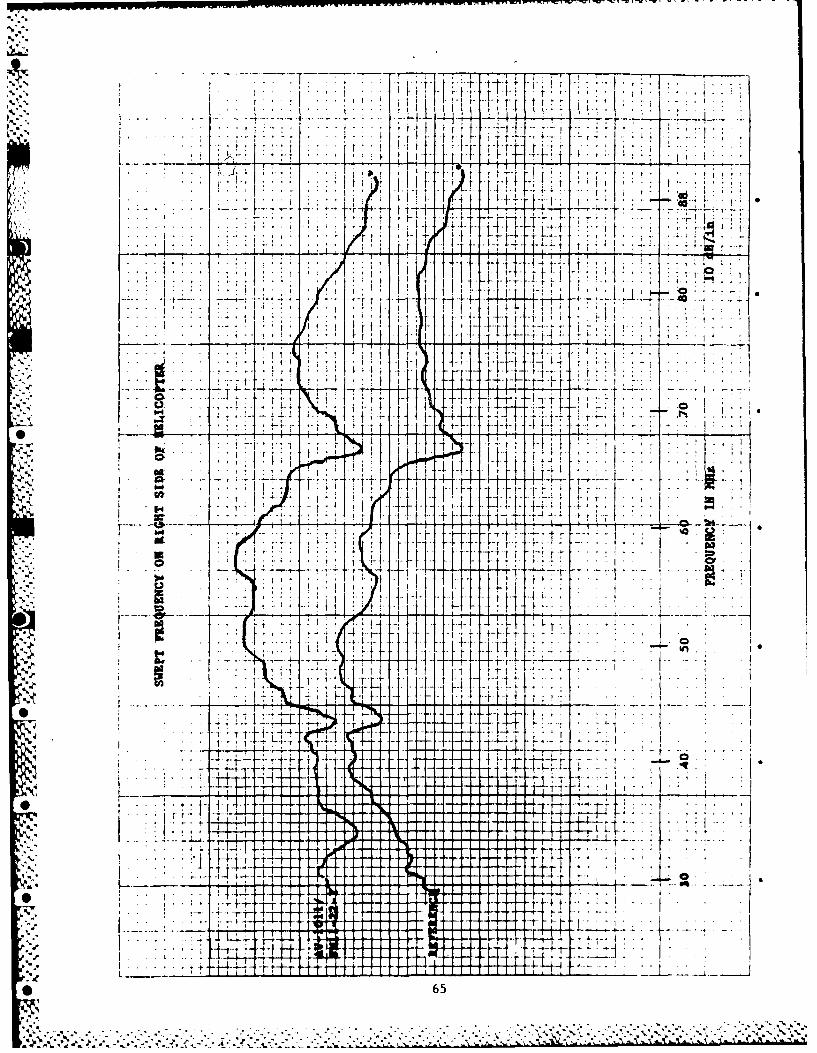
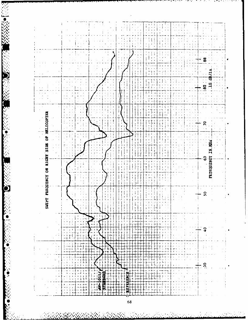
D. SWEPT FREQUENCY PATTERNS - RIGHT SIDE OF HELICOPTER 61
E. SWEPT FREQUENCY PATTERNS - FRONT OF HELICOPTER 71
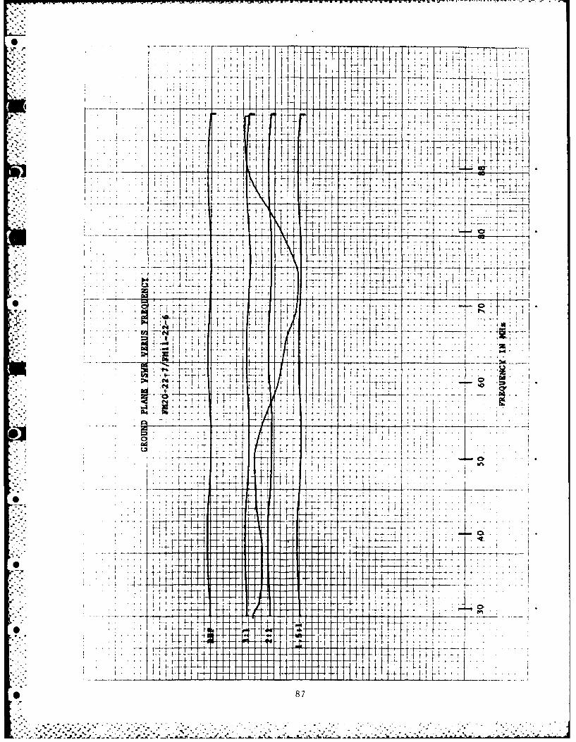
F. VSWR PLOTS - 32-FOOT GROUND PLANE 83
G. HELICOPTER VSWR PLOTS AT ANTENNA COUPLERS 93
H. HELICOPTER VSWR PLOTS THROUGH TRANSMISSION CABLE 103
Figures
I. 32-Foot Ground Plane 32. Ground Plane Range Setup 43. Helicopter Test Range Setup 54. Test Measurement Equipment Configuration 65. Test Equipment Configuration for VSWR Measurement 7
* 6. Antenna Locations on UH-IB Helicopter 8
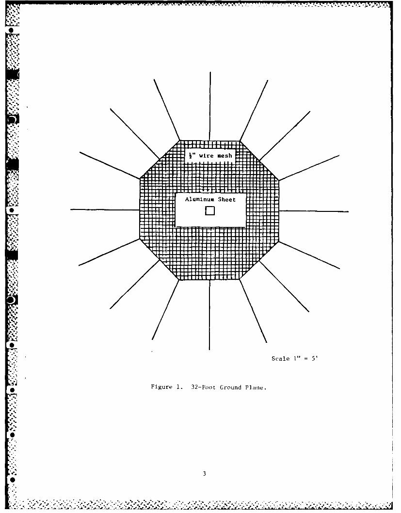
7. Full-Scale Helicopter Test Equipment Configuration 98. Gain Plot CU-942B Coupler 129. Gain Plot FM 20-22-7 Coupler 13
10. Gain Plot AV 11-401B Coupler 14
11. Gain Plot AV-1011 Coupler 15* 12. Gain Plot FM 10-22-6 Coupler 16
13. Gain Plot AO-1955 Coupler 17- 14. Gain Plot CU-942B and Avant Couplers 18
15. Gain Plot CU-942B and Dayton-Granger Coupler 19
16. Relative Gain Plot of Candidate Test Items 2017. Relative Gain Plot - Right Side of Helicopter 2118. Relative Gain Plot - Front of Helicopter 22
0i

1. TEST OBJECTIVE
The object of this test was to evaluate three candidate antenna couplers, usingdifferent combinations of whip antennas, to determine which combination, if any,best meets specifications as a replacement for the U.S. Army's UH-l Helicopter tailwhip antenna. The present in-service coupler, with different whip antennas, wasalso tested.
2. TEST ITEMS
The Antenna couplers were evaluated in the following configurations:
MODEL SERIAL NO. MANUFACTURER CONFIGURATION
CU-942B 00456 Comm Comp Corps Standard AS-1703 whip antenna
CU-942B 00456 Comm Comp Corps Dayton-Granger FM 11-22-7 whip
AV-1011 0001 Avant Avant standard whip antenna
AV-1011 0001 Avant Dayton-Granger FM 11-22-7 whip
FM 20-22-7 0012 Dayton-Granger Dayton-Granger FM 11-22-6 whip
FM 20-22-7 0012 Dayton-Granger Dayton-Granger FM 11-22-7 whip
AV I1-401B 0010 Avant Avant AV 10-401B whip
Although not considered a part of the evaluation, the following couplers were
also tested during different phases of the evaluation:
MODEL SERIAL NO. MANUFACTURER CONFIGURATION
AO-1955 001 AEL Standard AS-1703 whip
AO-1955 001 AEL Dayton-Granger FM 11-22-7 whip
FM 10-22-6 002 Dayton-Granger Dayton-Granger FM 11-22-6 whip
FM 10-22-6 002 Dayton-Granger Dayton-Granger FM 11-22-7 whip
CU-942B 523 Comm Comp Corps Standard AS-1703 whip
3. SPECIFICATIONSY. ,
The following specifications, as set forth by the U.S. Army, were used as aguide in the test evaluation:
Frequency Band: 30-88 MHz
Input Power: 50 Watts (5:1 Duty Cycle)
Antenna Gain: Gain at 30 MHz no more than 9 dB below gain at 40 MHz
VSWR: Less than 3.0:1
* Average Gain: Approximately -3 dB across the band
Gain Variation: ,Less than 10 dB across the band
-"

4. TEST FACILITY
The test measurements were conducted at the Naval Air Development Center An-tenna Test Facility, located in Warminster, PA. The test measurements were madeon two different test beds: a 32-foot ground plane and a full-scale UH-I Helicopter.
a. 32-Foot Ground Plane. Absolute gain and Voltage Standing Wave Ratio (VSWR)were measured on the 32-foot ground plane shown in Figure 1. The mounting of theground plane and the setup of the test range is shown in Figure 2.
b. Full-Scale Helicopter. Relative gain between test items and VSWR wasmeasured on a full-scale UH-I Helicopter which was transported to the test facility.The helicopter was placed on a 20- by 24-foot cement pad located 500 feet fromBuilding 115. Figure 3 shows how the test range was set up for these measurements.
5. TEST CONFIGURATIONS
Different test measurement equipment configurations were used for the differentmeasurements on the two test beds.
a. 32-Foot Ground Plane.
(1) Swept Frequency Gain Measurements. The test measurement equipment config-uration for the 32-foot ground plane is shown in Figure 4. Swept frequency gain
*measurements were made using the direct comparison method. The Standard Gain An-tenna (SGA) for this test was a 14.5-inch straight blade; Collins Model AS-3191/A.Its gain is directly traceable to tuned monopoles measured on the 31-foot groundplane.
For each measurement, the antenna coupler and the SGA were mounted on 1-footsquare aluminum plates which were flush mounted in the center of the ground plane.Each of the test items were connected to the receiver through a 6-dB -d to insurea good impedance match. All tests were conducted with the leading edge of the testitems facing the illuminating antenna and the ground plane tilted downward 20 de-grees.
(2) VSWR Measurements. For the VSWR measurements, the test equipment wasmoved to the roof area and configured as shown in Figure 5. For these measurements,the SWR Autotester was connected to the device under test through a 4-foot lengthof RG-214/U coaxial cable.
b. Full-Scale Helicopter.
(1) Swept Frequency Gain Measurements. The couplers with their associatedwhip antennas were mounted on the helicopter in their normal flight location asshown in Figure 6. Swept frequency measurements were made from the front and rightside of the helicopter.
The test measurement equipment was located in the equipment van and configured
as shown in Figure 7. The swept frequency signals were transmitted from an APN-995BLog Periodic Antenna and received by the test items. The reference antenna was a
CU-2331/A coupler with an AS-4085/A wide band whip mounted on a 4-foot ground plane.
(2) VSWR Measurements. The test equipment for the VSWR measurements on thehelicopter was configured the same as for the ground plane (Fig. 5). Because of the
* height of the helicopter tail section, a 15-foot length of RG-214/U coaxial cablehad to be used between the SWR Autotester and the device under test.
2 (text continues on page 10)
0%. . . . . . w
-NS
Scale 1"esh5
Fiur 1. 32-Foo Grun PlaneI0 f l
I0il
3i[II
-. ~ ~ ~ ~ ~ ~ ~ ~ I I,*~ I, till a , J P , .- * ~ ... < * '...... ~- + atl l

' . ".
-,j
.i3
-0 0
0"
.,,,. - .
'0
.- t --
- . .0
Ow
• ' %°

AS-4085\I
REFERENCEJ5
20' x 24'LOCATION OF
*CEMENT PAD HELICOPTER
200'
3qr4/APN- 995 B- TRANSMIT
EQUIPMENT[VAN
U 300'
* BUILDING 115
Figure 3. Test Range Setup.
5

.4 a4
4..'.4
03
u~cu
'-44
C) 90
C).
0o 0 .
U))
__7,p

MODKl. 640
RF
XN AL YZEKHOKIZ IP-7035B
X-YVYERr y RECORDER
RF
SWR
I AUTOTE:'rER
DEIC
I Figure 5. Test Equipment Configuration for VSWR Measurement.
I 7

-. 4
0
41
31 P4
,m Cl
E-4
= oz1-4 a" 0 1 "
z ~ -,
DN 4-0
cjca'4
0
00
04 4°0
*[U, u
1.-r4
>44
en.
% co
v" '-4
-- k.4
00 -.4
In.4

6. TEST PROCEDURE
a. Swept Frequency Gain Measurements. Throughout the test measurements, thetransmit field strength was monitored prior to the start of each sweep (via the ref-erence antenna shown in Figure 4). This was to assure that the level did not varyfrom one sweep to the next.
The SGA was mounted on the ground plane and its receive level was recorded over
the frequency band. This was done by setting the sweep oscillator for a slow singlesweep cycle (50 seconds) and then locking the receiver on the start frequency withthe Automatic Frequency Control (AFC). The oscillator was then triggered and the an-tenna response was plotted. The SGA was then removed, the first coupler with itsassociated whip antenna mounted, and its response recorded.
4. The above procedure was repeated for all of the test items.
b. VSWR on Ground Plane. VSWR was recorded using the equipment configurationin Figure 5. The "REF" and known VSWR traces were recorded by placing a short at theend of the 4-foot length of RG-214 coaxial cable where the test item is to be connec-ted and adding known attenuations in the "Return Loss" line according to the formula:
Return Loss = -20 Log VSWR-1• VSWR-I
e.g. 3:1 VSWR = 6.02 dB Return Loss
Once the reference lines were recorded, the attenuation in the "Return Loss"line was removed and the short at the end of the coaxial cable was replaced with thefirst test item. The VSWR of the test item was then recorded. This procedure wasrepeated for all test items.
c. Swept Frequency Gain Measurements on Helicopter. For each measurement, the* test item was mounted on the helicopter and connected Lu the zeceiver thruugh a 6-dB
pad and an RF switch. The other input port of the switch was connected to the refer-ence antenna through a 10-dB pad to reduce its receive level.
The reference antenna receive level was monitored prior to the start of eachsweep to assure that the transmit field strength did not vary from one sweep to thenext.
The receiver input was switched to the reference antenna and its response was
recorded over the frequency band. This was done by setting the sweep oscillator toa slow single cycle sweep (50 seconds) and then locking the receiver on the startfrequency with the Automatic Frequency Control (AFC) prior to the start of the sweep.The receiver input was then switched to the first test item and its response re-corded.
This procedure was repeated for all test items with the UH-l in the two testpositions: front and right side.
d. VSWR on Helicopter. VSWR was measured on the helicopter using the same pro-cedure as for the ground plane described in b above.
00

V7. DATA PRESENTATION
a. Ground Plane Swept Frequency Gain Data. The swept frequency data was re-duced and plotted in a frequency versus gain (dBi) format. The different possiblewhip antennas to be used with each test item were plotted on the same graph. Severalselected couplers were also plotted against the CU-942B/AS-1703 for comparison.
The gain plots are presented as follows:
Figure 8. CU-942B/AS-1703 and CU-942B/FM 11-22-7.
Figure 9. FM 20-22-7/FM 11-22-6 and FM 20-22-7/FM 11-227.
Figure 10. AV ll-401B/AV 1O-401B.
Figure 11. AV-lOll/Standard and AV-lOlI/FM 11-22-7.
Figure 12. FM 10-22-6/FM 11-22-6 and FM 10-22-6/FM 11-22-7.
Figure 13. AO-1955/AS-1703 and AO-1955/FM 11-22-7.
Figure 14. CU-942B/AS-1703, AV I1-401B/AV 10-401B and AV-l0I/FM 11-22-7.
Figure 15. CU-942B/AS-1703, FM 20-22-7/FM 11-22-6 and FM 20-22-7/FM 11-22-7.
The best combination of coupler and whip antenna for each candidate test itemwas then plotted against each other and the result is shown in Figure 16.
The swept frequency patterns on the ground plane were cataloged and are presen-ted in Appendix A as recorded.
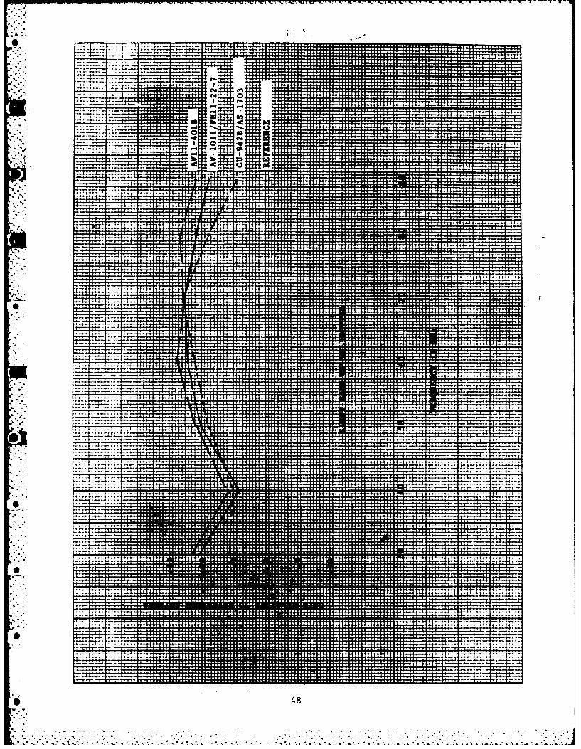
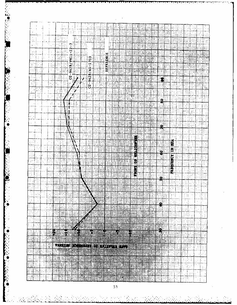
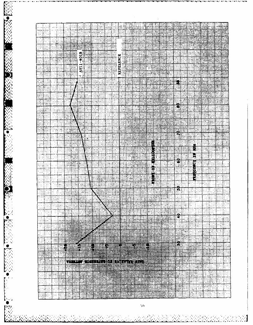
b. Helicopter SwepL Frequency Gain Data. The helicopter swept trequency datawas reduced and plotted against the output of the reference antenna. This was ac-complished by first normalizing the reference antenna signal level and plotting thetest item deviation from that level. Although the data measured on the 32-footground plane shows a flat response over the 30-88 MHz frequency band for some ofthe antennas, the data measured on the helicopter shows more extreme data variations.This may or may not actually occur since absolute gain was not measured. However,
it is not inconceivable that these gain perturbations could have occurred when theA antennas were mounted on the helicopter. Although the plotted levels are not absolute•_ values, they are relative to each other and show the gain differences between the
test items. The gain plots have been cataloged and are presented in the Appendicesas follows:
Appendix B. Right Side of Helicopter
* Appendix C. Front of Helicopter
The relative gain between the best combination of coupler and whip antenna foreach candidate test item was then plotted against each other and the CU-942B/AS-1703.This was accomplished by first normalizing the CU-942B signal level and plotting thetest item deviation from that level. The results are presented as follows:
Figure 17. Right Side of Helicopter.
Figure 18. Front of Helicopter.
* ii (text continues on page 23)

----. - - 1~-
N~ W-I
I f - ------.------ -i
.............................
- - - - --- -- .----- - - - - - - - -
____ ___ _ - __ ____ __ - ------ --- s
000
'-4
--- ~~~ -- - -- - -- - -
______-'R _____ <vjI RA_ _ _ _ __ _ _ _ _
-1-12-I.-

I ~ ~ ~ .. -. .. ., - ____ __
--- ---- ------+- -- 4 4 ------
- -'
C0
a-a
aa - ~ .. .. .. .. . . . ....
.. a.. .......
'~~~~~ --- -~L -~ --- -. --. -* -

7__ -- - -- - ----- - - - 7 - -. 77
.~.,7-7
0q
-~ F7 ~7~V F7 ~ CL
..-........
044
i' .. ....[
-7 . ....
-~ : ......... _.
... --7F ------- -70 07 --
I, A, .
4. 14-~-.7 ,

-----------
- -1 ~ ----- -----
_. ... .... .... .-....:. i .r .. . i . ,
.... -. 0
1- -------
4. ....-. , .... .
t......... "l
.. * . .. 0
::A
" -" :...... , . . .;: :
..... . ---- .--- 7-
--- --- ---
10 1 .1,
-- - ---- -------
* I -I
" ' ' • ! . . . . i i i i [ ! ! i , , . * . . . . . . . . . .. . . ... ..... i
"- . . . . .H - . .. . . . . . .I; _ . . . . . . -i . . . . . .. ,. . . . .
15! I
\ '. . .' . -% . -'-I.., . -." . . . "-"I. .'.1%- ."""" "''''- .*..' '; --- ' '-K." --.-- *. ' ' ' "-".-. ".-

..... .... ... .... ........ .... .... ....
.... . .... ...... .... ... . . ....I'T
--------- --... ... .. . . ---- -- -- --------
p.
------ -------w
p:
-7
77a -
w, aw771 ik : ra q .
To: a i : a+- --l 77-7 QJ
.... .... tk ::... .. ........
CN... .... ... C14
Inn - .... ....
........ .... .... .... . . .. ..... ....
....... cl, m w. m
A
4:774 1': CN... .... .... in ..:i .... ....... --: -4 - -T7- --------- ------ ----
.. ....... . . :sl
. . .... ....
-7 7 ..... ...... .........
'::T7
wrp
go
a w
....... ..... + 7
w6
---- --- ------ --9p pit' RUT Omp
film .
.... ......... ....
7 --------- - ---------
m:
7 . ......... .........
%

-- -- -- --
-- - -- - -- -
----- -- ... .. .....
. 4 .----- -------
44 j4 a_ _ _ --I
.. .. . ... 4
-----> ---- ------
--- -- -- ---
1 4

--- --
* r-. - .------------
f l - ---- -- - --- ---- ---- - -- -- -- - ----- -
!2 . .. ..
wtI.
IZ 7 r: a
...... ..
To ia . /i~ 2L1.
----- -- --
--- ~~~~- - -- . . ... . .

-*l: a .A --r' ----
-- -- ---- -- --. ..
" i
.. .... ..... ....
i s-
:'.~~~~~. ......, l i ....w- .o
. ..----- --.. ., -- ---
-• - - -., . I7:
--- ---- -----
-._ ...... .... ....... -. +....... .. . ..
', ,.-
! ] --- ------ -----: ..... . .. .
- I . _ ::.:
IP
,- • : C ' . . _- i . C_.
-:1:
119*
. .. . : . .. -- - - 1 _ ...
. 4 . ." ' ,1
i -- . . .:_ '. . .. ... ... .
I 19
: : : : . .. " :" :- ::: ::"", ":" "4": -,i i ;i : , , :. ,i

..-- • •. . . ..
C- -- ---. . . ---. .1 -
- -- -1 - - - - - -- - - - - - - - -
t.I ..
I " ; I
------ ------- - --------- - --- ---iw
. .......
-... ------.
4-1
.- --- ----- ---
. . ...... .
em I
--- -- - -- -- - - - --- -
.
- ---- --- ---
-- - - - -- - -- -
-- --- ~ . - - - - ------ ~----
p a a
20

-7 a
C,4... .. .. .
I ...... ...... ---------
7-. . . . 7 . .. 7 - - -. - Q
t- -- ---- c - --- -- -- --
.. .. .. L.
-4--- it 1 ~v:...: . .......
' . 0
.. .... .. ...._
- -7- -777

-4.4
* +4
---- . ...
c'41
I.LCL
-- ' 4 ---- .-~- -J 7 -- - - 7
. 0
-*.. .. 4J_ _ -~0
-rr
77- - - t1-
4 4
zzcz
022

The swept frequency patterns have been cataloged and are presented in the Ap-
pendices as follows:
Appendix D. Right Side of Helicopter
Appendix E. Front of Helicopter
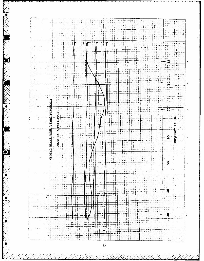
c. Ground Plane VSWR Data. The VSWR data measured on the 32-foot ground planewas cataloged and is presented in Appendix F as recorded.
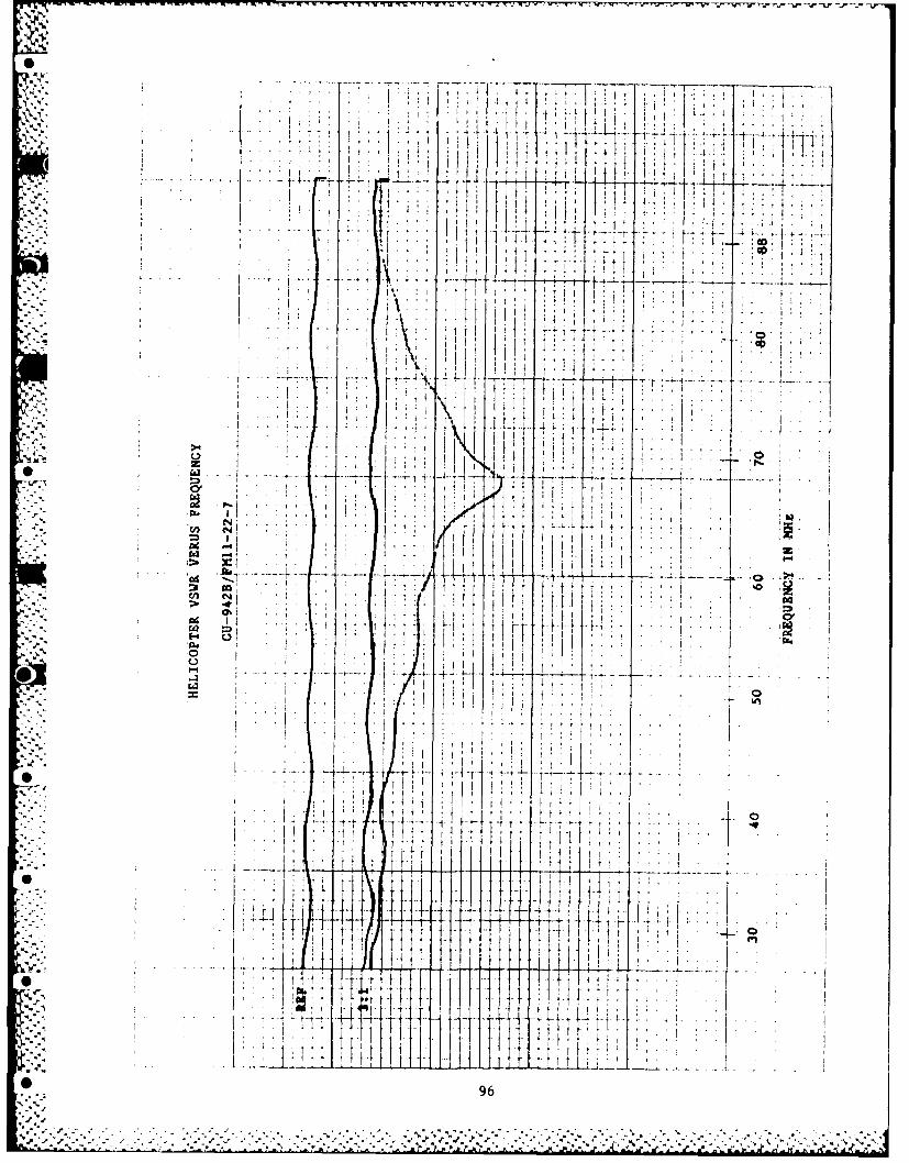
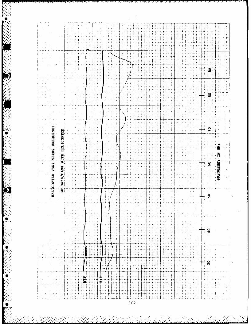
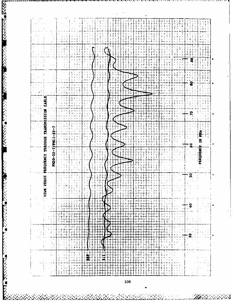
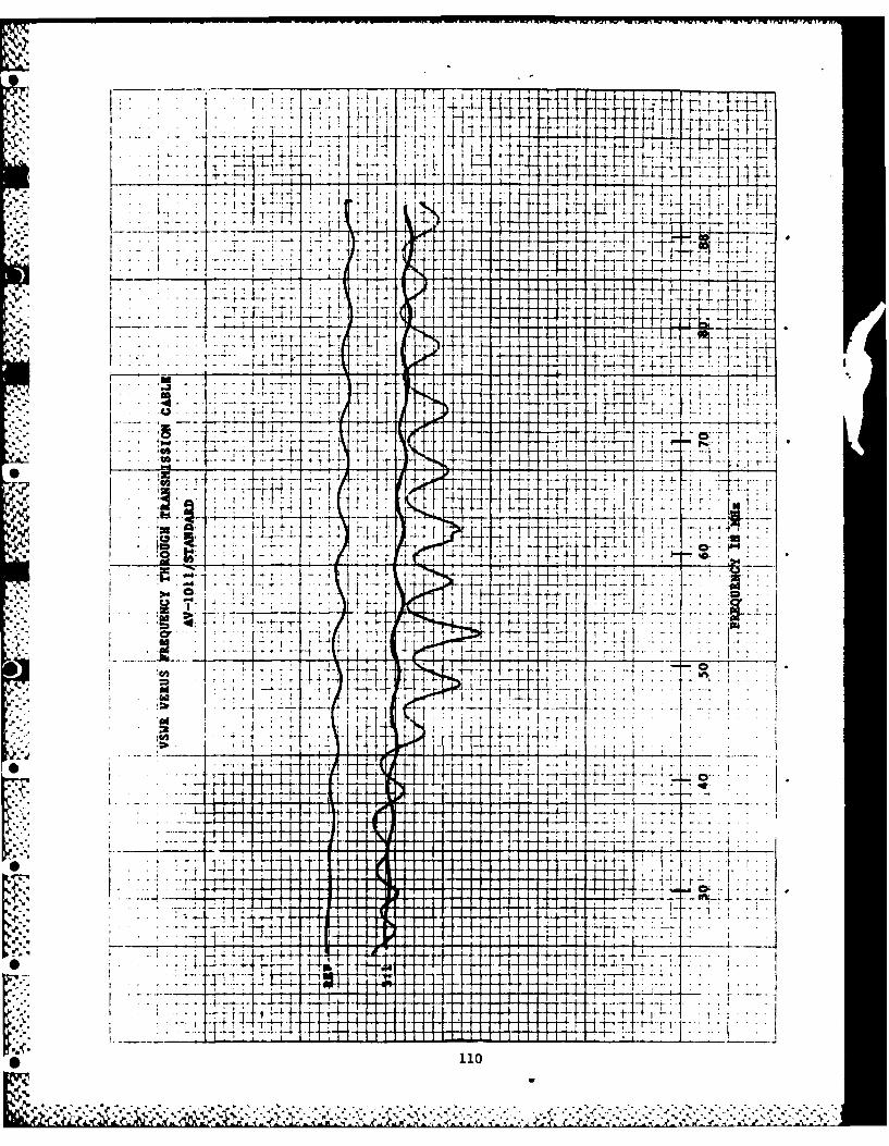
c. Helicopter VSWR Data. VSWR data was measured on the UH-1 Helicopter in twodifferent ways: directly at the coaxial connector of the whip and coupler assemblyand through the helicopter RG-223/U coaxial transmission cable which was disconnec-ted at the radio RF connector.
The data as measured through the transmission cable show the VSWR presented tothe communication equipment in actual operation. The UH-1 in-service CU-942B VSWRwas also measured at this time.
The VSWR plots are presented as follows:
Appendix G. VSWR at Couplers
Appendix H. VSWR through Transmission Cable
* 8. SUMMARY
As stated earlier, the purpose of this test was to determine which of the an-
tenna coupler and whip combinations complied with the following specifications:
Frequency Band: 30-88 MHz
Input Power: 50 Watts (5:1 Duty Cycle)
Antenna Gain: Gain at 30 MHz no more than 9 dB below gain at 40 MHz
VSWR: Less than 3.0:1
Average Gain: Approximately -3 dBi across the band
Gain Variation: Less than 10 dB across the band
The average VSWR was calculated using the same seven (7) frequencies for alltest items. The average gain was calculated using the five (5) frequencies for whichthe dBi gain had been measured.
*' A comparison of the different test item configurations versus the above speci-fications is as follows:
23
0r

FM 20-22-7/FM 11-22-6 Max. VSWR Gnd Plane: 2.9:1
Aircraft: 2.6:1
Avg. VSWR Gnd Plane: 2.1:1
Aircraft: 1.89:1
Gain Variation Grid Plane: 8.9 dB
Avg. Gain Gnd Plane: 1.7 dBi
FM 20-22-7/FM 11-22-7 Max. VSWR Gnd Plane: 2.9:1
Aircraft: 2.6:1
Avg. VSWR Gnd Plane: 2.1:1
Aircraft: 1.88:1
Gain Variation Gnd Plane: 9.9 dB
Avg. Gain Gnd Plane: 0.1 dBi
AV-1011/FM 11-22-7 Max. VSWR Gnd Plane: 2.7:1
Aircraft: 3.15:1 at 34.5 MHz
Avg. VSWR Gnd Plane: 2.0:1
Aircraft: 2.0:1
Gain Variation Gnd Plane: 7.2 dB
Avg. Gain Gnd Plane: 0.6 dBi
AV-101l/Standard Max. VSWR Gnd Plane: 2.9:1
Aircraft: 3.25:1 at 35 MHz
Avg. VSWR Gnd Plane: 2.4:1
Aircraft: 2.25:1
* Gain Variation Gnd Plane: 5.95 dB
Avg. Gain Gnd Plane: 0.2 dBi
. AV 1l-401B/AV IO-501B Max. VSWR Gnd Plane: 3.2:1 at 30 MHz
Aircraft: 3.4:1 at 32.5 MHz
Avg. VSWR Gnd Plane: 1.9:1
Aircraft: 1.83:1
Gain Variation Gnd Plane: 5.45 dB
Avg. Gain Gnd Plane: 0.7 dBi
* 24
-- v

The specifications that the gain at 30 MHz be no more than 9 dB below the gain
at 40 MHz and the average gain (-3 dBi across the band) are met by all candidatetest items.
As noted in paragraph 8, the Dayton-Granger Model FM 20-22-7/FM 11-22-6 fullymeets the stated specifications. The VSWR as measured on the ground plane and
helicopter is less than 3.0:1. The requirement for a gain variation of less than10 dB across the band is also met.
The Dayton-Granger Model FM 20-22-7/FM 11-22-7 also meets the stated specifi-cations. The VSWR as measured on the ground plane and the helicopter is less than3.0:1. The gain variation specification is also met but just barely (9.9 dB).
The Avant Model AV-0OI/FM 11-22-7 meets all of the specifications except for1 4, the maximum VSWR on the helicopter. This out of specification is over a very nar-
row portion of the frequency band (34 to 36.5 MHz) with the maximum VSWR of 3.15:1
occurring at 34.5 MHz.The Avant Model AV-1011/Standard has a flatter frequency response across the
frequency band (5.95 dB) but the helicopter VSWR also exceeds the specifications atS the low end of the band (33.5 to 38 MHz) with a maximum VSWR of 3.25:1 occurring at
35 MHz.
S .The Avant Model AV I-401B/AV 10-401B has the flattest of all of the frequencyresponses (5.45 dB) and the best average VSWR measured on the helicopter. However,the maximum VSWR on the helicopter exceeds the specification at the very low endof the frequency band (31 to 35 MHz) with a maximum of 3.4:1 occurring at 32.5 MHz.
-1.'.
.4 1.
25 (Page 26 is blank)
0Z

APPENDIX A. SWEPT FREQUENCY PATTERNS -32-FOOT GROUND PLANE
0
27 (page 28 is blank)

. 4
,. . .......
4..
I -1.*I.... .. .
. . .. K ... . ,* .. . . .
I- *1**"*+
. .. . . . ..-+ I . ..
e .... ... ..... ............ o+ - +'+ ..*1 '. 1 ' iil ii:
2 *.
T7
t t'
. . . . . . .IT.4_11.Tv 4-
t- I4 O
I t 1 1 -. t--
~--- --- -,-- - -~I *
1I2 ~ 41 ,
-~30

-7
. ... : l ift ii i
- • ,,.
iT~IT
.. .fff . .
.1 • I T 14
. . . i . I
.. . .. . . I, " tj .I
-, .... , - ... . .. . . .. - -
. rI
.1 .
31.'• t- ... ..."I ' I. . .
-I. . . e.. . I ?..... ... . . - .... . .
.. .. . . .t 'I ' I
"'" .. .. T . " .. i , ; . 0
,' .' . , .-f-t --" 1 " I ' ""I ' ' t l " . .. 0
" "H i' , ! ! I . . . " I -I .
I I , I I-I .-. _ + -.. .
.1-, +, ! - '- r ,1-i f
* 31
........................... ,.........-" -' %"
" '-. , -" " "- -' -' -""""'", -,' "- .,.""-.'-""' ' ""-"-, - -. '.' "- '-.'." ". '. . . *. * * " .- *'- )' - "....v..' , ,,- ', -- ' - ' -," '- _ ,"'"", ,*""" .- ',

. . . .
t r
94t .. ,
OF +
I~ 41
10-1
i~i t
* .,**,* . t.4.~.L32
Cd -6'A

I . I r ....: ....i .t-. t
. . . . . . . . . .. ..
I- % . • ', '• tp , .. .
. . . . * '* ' t '' . :
* . . .. . . . . . t , , ., . .
" . -.. ..- r . ....- !" - •
'."- "" ,,-
,,I i i i: ° ' .. . tr...
• - . '.-_ . . .. : ., .. .. . [ , 4, . : ;.
. . . . **i*< .... ... . . _..,
" '" .. . . . ' i ; .. ... . . .
., ,.. .. ... . ,
;:-I" .
.'.-. . . . i . . . . 4-.. . -.. ,... . ' ,. -, T . .
-' .. . . . . . . . . . . . .I- -- .*. . . . . . ...
"-.. -,__-.-. . . . .. '4..... ...-.........
:. .. . . . .. . . . ......... .
_.. ...... ,, +.

t ~ ~ -tT-
TI- V-4-1rV
i~~~~ r 4r4;L
144
EL -L
14 4
0~ *0r.

•~~~ ~ ... .. . ; , ... .. .. . .,
,~~ ~~ .. . .. . . .. . . .. . . . . .' ' ; ' ;'
T ~~~~~~. . . . . . . . . .. .. . . . . .. . . . ' '
.. . . . . . . .! . .
1I,,
, * " ' ... . .. .... .... .;2r .4 t .. .. ! .. . •. . .
* I t
:_
,, T 7 T V J .. : . ' . . :,-,
. .~ i ... : i ,. . 2 T 7 ,,. ; -,"*1•'
" '1" ,," - +- '
.. . .. .... . . .. .. . . .. 0. _-.. F: . .. . :: ,0':.
,::.0 T .
1 1 I
+ +
. . . .
_ "
.. . I.... .
, ., .,, .. .. 'F F: : : .. .*I . .. .0. .. . . . . . . .. . .. ' ..
. . . . . . . .. .: " .. : - ,I ' , F , - , - , . i • !
." -, F! ] . - , :,,- *-t .. . - " .. . . .
K ..... . .' ' ] i l ,[ " " ' !l ' I i
! u
'- - j*-" " - . .. .
:__ K b 4~ r, ! -f.4 j ;i i4 k -r -- ' F , 1 - . .. . .
1 "- '

. . . . ..K .. .
I T,
.-
t~ r-
i Mt
I-T
t~~ L 1 1 --. -.It,
16'

....... . ". ".." "'v'w - -
tr--~................................... ,........ : ......................................
+r +
". t t
,•-
r r t t*~~ ~ -. .*t-: 1 ;: _ :I 2 ......
,.. ,
t t
T 1 _44T
4 f 4--.. .. _ .,. . _ _ _ _.._
1-4 " I . . 4i- 4i . o
* . ' 4 tt. , " ' .-'i
I- ... i-4 •i-*-*-* I. •
... . 4 . .
• 3 7
..- r " " " ' " ". :! : : : : ! " : : - : -) : " ' " :
~~44
TTFT
4 T -- t. '-. 7:77T:)7Ti::<~7;iCL-4~
-7I L .
I t
"17'' N r t
'-41
4 -,7
T2 4 ___
-. 7 V+
4*447* 38ij-
W~~~~j.7T 4 -
* : .
- + Cod I
T*~ t1 V ,
It I. T
'T ..
S.-*T... 1 1. + yr T I
-1. T~ I'I
_______________t I ;.1*T
I J -11 '1 1
+ l II +.~F1 T. Tr
t '-'I
J. --4 IT+
39 (Pag 40 is blank)

0'
4
N
S
..'
~
0
A
0*
S
S..
'V
*'VV - V - - , **V~. V - V 4**VV ~.--.. 'V
5 - - - -. VV. - V. V V
* b ~ ' ~- ~ .~ V V ~'''' VA VV ~..

.~. .~
APPENDIX B. GAIN PLOTS - RIGHT SIDE OF HELICOPTER441
A.
.44
- -'4.
0
S
*1
0
0
41 (page 42 is blank)
0'4
'4
.- 'A-~.'.4
. *. **,

-7-7"K-117-07%
j
-- tri
Cl
1od
... ... C4 C1444 44 - M i
:;= ': 0, Lt.
lei
4 -+44t ttJ4
+ 4.;
4 " L
-1
4- 44-4
44 4-
4.+ +
t
i7 r77- 4-i
4- 4
14+
+4-
::7
L
zi
t7

7- 1-
-tt :-fL- rm
1
4,4
44t* . ;t L.
.~ .........
--- ---
7~~z -4?4 C-,
S
S7 h d++ -. 4-
Sc
S4
S=

- rrrrw~~rwr,.w flWV r,.4- f ,- .~. - ~ ~ ~
* * -....- . . ....
. . . . . . . . .. . .. . . .. .
-... .... . .. ....... .-
............ > -

- - - - - - - - - - - - let Ile I Will 4 ill
7-
10-4
04
-4-
4 T. . . . . ............
OIF .. .. T-T 4444
.44
t
4+++
F r
4V
7t :t' 4v T+4-t -t+44.++44, f-4-
-14,:7
+ t
u=:............ 444
=77
444
.... ...... ..
- ------ 177
f
4--
+4
. ... .. ... .. ... . ... .. ... ... .. ... .. .
.. ... ... ..
d
--- - ------- ---
W4...... .... ...... ........ .. .....
........................ .. . . . - I ..................... ...... ........
........ ......- ---- ---- ------- .... ... ....... .. . .
... .. ... ..... .. .. .. . . ....
. ..... .......... . .... ............. .. ...
.. . ... .. ... . . . ... ...
... . ..... ..
... .. ......
............. .... . ........
.......... ..... . ... ... ......
.... ..........---- - .. ... ..
.... ........ .. .
... ... . . .. ...
.. . . .. .. ..
.......... ..
........... ... .
....... ...
..............
... ... .......... . .... ..
.. . ............ ..... ....
........ .. .. ... .. .. -- --
.. ..... .... ......... ...........
............
.... ... ............-- -- -------- --
.. .........
. .... .....
............
.... .........
. .. . . . .. ..
.. .. .. .. .. .... .. .. .. .. .. ... .. ......................
................... ....
......................................
..... .... .------------
-- --------
.. . .. . . ... .
. ...... ..... ......... ............. . " 44,
.... ....................
. .. .... .. . .... . ............. 1:7
.. .... .. ... ... . . ....... . . ....
::r-
HH4111-111 i........... I .......
IM-1 Ill' I'llil. ...........
48
1 A

0 .
L p4t~crv
2 {r.~tt+~i&t... .~ .".I
-.
4. $. I- ~
i r rI /1- /
I~
C* 34
9 .
2~
..:; r
.. -- ..- I__________ IA - -
* . . . U . j*W" 2-
.21?. - I ,. . -.- iv 14~u.t2sti.:; C
IA-J
a
~tk*
* j~jI- +~:4L....-744
- ..-.--
It-. .9..+4.~4-4~ .4.
1.4.. hz: 424:;:..........~ : ~.z:n ; . 2tliSA I ~W '.'
0
L -i. = , + ...
APENI CAI.POS. ROT FHEIOPE
51(.I N s I ni
-.- APEDI C GAI PLOTS - FRN OF HELICOPTER.
" ,+-
7K7 7-7 -7717-
I ~ *-4~4 . .... ..... } i .
4; __'T 71. 77177:!T.;7: -7
)c 0 ' .... ....
f ri
I -4,-- r
71 41-
- - , - ! -' ';
7 , ... ....
... .. +
tyi4 J ii~~'41
S;53T

. . . . ... ...
:-J.
... .. .... .. ..77, 77 -,-717 .7.~''
...........................................
.t. .. ... ... .. ... .
....... ... ...* ~iTI
. .... .....
-r--t--~~~~ ......-- P 7~9i~- - rj
r I8
ii7 .
.. ..2 .7 7
...~ .
..............4>.. 7.r 14- -
I4 T
~+1.1 ~f~t4
I TL L

-~~~ -- *. **4
7r7 . .. . .4
i-4 -
I-
6~ cn
7:.
/u '7' '1..
r- F. 4 +f
7 4.4 ,,
II
4. vu :;1 51
.7777=
4<V'
.7::
-~~~~~~~L.. -. -. 7. . . . . . . . .. ± -~

S+
.. s. T
-:11 t
0H
* 57
+4......................................

1 -r7I' -l H--.4
T4t i1 - =u
* .... ... . . . . . . . .

77 4.. ....7 .. 4..711.______ lJ' -44 - - ~ - -
. ... . . .. .. .
... ... .. . . . . ... . .. _ _ _ _
-.C14- (%,
---- ------ -

APPENDIX D. SWEPT FREQUENCY PATTERNS -RIGHT SIDE OF HELICOPTER
pp
61(pg 6 i lak
9 .. . -. . .- .. .- . -1 . . .T, . . , ,'.- . .-.- .-. . _. ." - .- .- .- - ' . ." . .-..- - -- -.
.., r , i , , , " ' '
*rI
'r I.0 T
t
:7-:7
".", " -l 7ts .
-~~~ T , i , . .
44,4
$"%. L I L "
-- -r--d -- 1 --
..... ,- I .. ..
... 63I"-
. ."
.. ...
" - -"
-"I -' - .. .. -FI: = _- L
.4.. I . . .. .
:44 $ .~i4~ t j63.....,. _..,..;.-..-,....: -:.2.... . .... , -.-. .. : '...... .... , .-/.: -,,,: . .. . .; ,,. , _i>' O ' ,, ,' ,:4.

I I
7 T
I r ft
4
Ti ~
1 t
14 T' ~
I T
4Tiii Y- [I
* ~4{ ~ ~ii.~4iu1' .- j'.64
.11,
'I
f I
4.4'I.-T II
1~ A___t Tp
-~T-1
, T t4l
j 7' .. .. .
'-T-La
*4 -t Ht"
IIF4*
L.. 65

I. . .. I4 .. . . I
1- -I I 1 L
IT 4-r j-.-1-.-
LI t
T -r-
'4 4+
I- .If
r I
0 -61

7 ,.S" ... ...... . I+. . . .. ..
I'
....... I... . ,
I. , ! + : -i l
.. .. ..
I t
..... I.,i
'i
,• .I t,
r1 IF~
":'":: ' .. .
. .4..
,..
* -"-~ " .. .. .. .. .. .. - T+- .-- --- ... 4 L -- 2 4
S , l .. ... . . ,
"I" ', + :+ i,.
'111.1 + - - i -.--
" " ji
"'
I '
I i 'li- . _ 1"1
'
1-L4
- irT
t +
2
I IIT
4T I
5" " ....t + , -+ i;+
"+ -"[ '
. . .- . . . . .. . _
T'
-1t
tji-I. ..-. i
I- I
I.ii ' -': :" i
* ........
r,,- :i .- 'I7~~~i 4 --.. i---_-': L... .._ _
:_
_-" : !
-- . . .::
I..
* .1
* . I.. ..... Ti
I .. r..F *F t
r 11
jtit
o .4', ~ iI68

4-- t t
-r;.0
t .T
iI.+,T
LTIT.J~~~~~-t T -t . 1 4 I
4-r
I69.

r .* .'*
..
:-'--'- APPEf'lDIX E. SWEPT FREQUENCY PATTERNS - FRONT OF HEL.ICOPTER
.-
,0 -
,1.-
"4-."
,,'.7S a'7 sbak
0 - " " - ' - ° - " " " ' " " - ' - -" " - " " " -. . " " - - i % ..i i . . " . i ~ - . ? i i i

.- 4, .
-T j
I I
At -Ti 4-I i i
-s.---- I t t47
be I -i4 -I INfil
I 0Hi,
71*T
o r * I73

A- 7. *, 77
-. 7 7
I r
t T t
4.4
-I '
ITlh -7I 1 T
HII-i L+4i
0 74

-. -r f~ w .-- - --
-4-
-4 i
-- -1 - -1-.----- I
* 1* ~ ~ .4v;
I. .. .*,~t
'444i A 4 t i~ii tI
44
..... r~~r 1 7T
_____7~7~T.4;w:~IV4
*~~~~: +. __ _ _1L:' T.I -
75

04...._ ...... I.4-,,
:-I.4
r 77T77 1*,I i ' f rI , I ,II ,
.
.. ..
.. . . .t 0,. ..... .t....r,
17 T T~. , ... ,K::1 1 t''7' 1> I .
.....~ ~ . ... . ..... ,.
l.a -4 -r
! rr f1L . .-~-- o _,:...
. I I T - - --- T
... ~....* :- -' l t : -
t
'
I SO...r
"""" .. . " ~i .... LI t.--l "+?/i; ' . .. *
:..:j' i ,. :+ . ,,, .
__t . _
' I.'.v" -__ _ _ _ _
_ _ _ __- -_
____- -_
__, -_.. .. . . .._ _. ._
• .--t 7..6;
"'" .... .t i-' .'- .. .-!.- 7-

r tI
- t t
- I - i, < I H~ -1-
-~~ -:~ 7rp
-H~ -i
Lit tt t t 4
i~t-
TT - At L..
4 77

.. . I . . .• • •.
* ,. ......... . 'o . ,,,,,,,, . .. .
. . .. . T t' 1 1 . .
4 7.. 4.. .
-to
T '-..
I . 44; t ' . . - .--1
-- .* 1. '- . . .
4 t ,
'to I " T
.. 4 L . . .. . .. 4 . . _ , ,• , ,
0* .. , .... -,~I T j . . 1 L
,,, - " . . . *' i i T ]
1,4 44- F tz
1 * .t . • ,
i-J I I
• ; . . .... 1 ] - I- . .. .
T, t
I0 * I It . j $ t i t - - r t - '-. . 1 . .
--I -FT- -+' - -,
I I I L F ...
I"
mI: :~~~.., .. .. .. ............ ............-r -- -I. . .. ..
4-.'H
I . ,'I . . . . 4,- -i 4- k -.. .. . . -t- - - V : . . . . .
I____i.. . 1 - -/-lr. -t. . . -- .t .l
;4. , . , . | - - - - - - - - ,.4. . - ' ' ' '
O" 78
N"

T I' rz),-, ', ;
* -. .1 t:
1.4 II
z Kr
T T-
*~ IYr t'
I;T TI. I " .4rli79

* 14 1 .
I~ ~ I I 4**if'
* 4D
I . . .- . 4 . .
+~:~:
.+.
7 Oqv. T
4 *-d -
I t
o 4>4I ' 4
4 '4 1 . .T
+ -4
4- T*-. t I7
+~, !t - - - -
I I * I 8 0

-. 11
ra I
o t ............
.-k,,
z : -.- -
tz I I~
. . . . . ... . .
7 t.T. .
tv-v -
(Page 82 is b I ank)
A Dii

APPENDIX F. VSWR PLOTS -32-FOOT GROUND PLANE
0
83 (page 84 is blank)
%0

i I?%,
K... 1 - I
"
4t-
,T- -T - '"-!"-
r. 7T',
T 4.
LI~~ bt 1
K.J+ ~ + <
" t t -'-4,- t -T -, ,- , 4 L .- . . - -4-7,, ,
. . ... ... . -}_t-,_- .V,7. . . . . . . .*....7TK ..... . . , -- -,I
Iin
' JI-rFP 4 vj' - +r-] '
I- 17A.i ... ' I ' .
" - ' I"r[_' ' I* :1 .--', -,-.'. V . t-i, t r : . . . . . . .. ,
. . . ... . ; "-t . . " . . . . , - i
I
-IV4 F -' 4 , ... . .. o ..
1 1 '
....... ,4 4 r ; 5tj : 7
85

TFTr777T, +:; 77 '
+ *1- 7t
+ T7tlt
I T I- t -- 4-- T- I-.I -1
1 i4-
i244 r'-- 4t t-
.1 L L-77t - t
fm T
T- F
44
TT t-H-T- 1 4-' 1
~~~i;0~~~ , t 5 E ~ KA.44
t86-~~~ ~ t - 4.
4 -'~ +4 ..
-T4 4
-~ ~~ ~~~~~~ t . - -r ~ rr.~. n r ' ~ .- 4
+ fI. I. ~ *'-L4'
4~ V-4--
t t
+ +
'I tt~~~ I! I t ;I K
C-.4 T4.
*11 7.m
+ t
;771 44 +4 +: - _
4 ft~~~la.1St
+. .**.Lj iH
87
t---r- -t~~
t r qi7~7. 4
- ----- -, I- "--!- . L j
7t Co
L.1I.+
-a41-
- :.: T2.7< 4 t~
tt 1i ~
*~~~~TT ---
- ------- -
1-~ +7 4
4-4F -
* I 1T
T 88 :>...

,m l , l
.. . . .. . .. . . .. . . . .... . .. . . . . ., . . . . . .. ..
i. .
I 7,
........ ,,, *,, -1.... .. .
t_ I : t
_.~_ _ _ _ _ _ _ . It - 7 T' + + . . .. .....
F T (. .
I +V
I I 1~ - - 4 4 'F A -T -.. ,-
..
..I
• "+, "" +" T-- "-- r--' --- ...-.. .-.- -. 1
7 fT T
""<- l- " .
1•i.. . . : t "
.....~1 , . ..
....
, r i.
.,
.7~ -T''
4"
"
.'.
....
I. ; . . .
.t. ,
.' '*+..
.
,.--I-.-!
. . . . T +IiL ' .-- ii j! ...... , .....
* 7-- - -li T :; T I, : :-I 44 ,
H
..r't
4 ..L
,. ..IL ...
. 4
.. ... L L I I+I+P4j~ 7 ; ______ .. .. 1
.9 .. . .. _ .
1- ..__ _ __ , ,_
. . . . . . .r - ,- I +
i +' - " .
.'
.. . . . . .. . . . ...9..!
__ ; i ..

. . ...
4 It
ttv44tr~ r.4Fth
4
T TT: - I'-,
1'
.. ,-T 1 #
Lt f4 -4 -- - F
4, ~ t
77TTflr r*
90V

N------------------ ----------------------- ,.. J ru vw 'ni- --- n ------------ .
1:1'~ rA
**
'-4-1
* II
T~ 4-~ 77 <j
T T 1 i-A-
T- 1
t-77 7:W .,t 4 T d +-
-J t - -
1 4 4-t T-7r
- ~ ~~ ~ ~ -- ' ----- Ii4
- ~ ~ 4 -
... j
-j +
T

~APPENDIX G. HELICOPTER VSWR PLOTS AT ANTENNA COUPLERS
:0
0.-I
0 q,
""93 (page 94 is blank)
., -%

I- 4 .t
<I?
. , 7 I
'-" :::. . .. P:iT p !i -2I ... .. ..:.- .. ... . ., ... . I. ....... ..It,,!
S... ...... . .... ...
T t
',. .. .. . . .
1. . -t
1i r ! : i i' ' l
f f I T . ..
;.. .I . .. 4- I r - - .;
0.':. 1if7C ' *
I I t
" " - .. .. .1
""6: L 21 . L : ,, .
4 :1............. .. . ...... ,rrr: I.. .
* : ' 1 ' t. i : r '
T117: l+tTTT
K-I :+ 444. ' '.I
J. J .. ... pN+ - + , . . ...M:,I r. . .. ; '1.
!ll 1....... ++ + +.+
T '
It
I 44
> --4f- 1-...-
14-T I Ti
96~T~

4't .
* . ~ . ,~ -410
7'! ,,~!777
,ti:t ;
It -4 . r
lpHr77........t, !
+ 7 ,. ,
* V 7777 ~777 ~tT T TT TTTt
.,~ *' fi97

til
:.: :'
tiI
c
.
-1, t t'
II . . .
,T -t t4
. .. . .. bI [. .1
40 1
I '-r-r-' ,-- ;4 . -- ,- ,- ... .
$ 1 f' • 1 " I -i - . . ..
.I:..:. " * ,t . *l t;
.. -* : ,. ; , 2I , , ,F
--- I1 -iiJ.IiII.........
c Z 4.
i! !i ;=
"*'" " . .. . .. .+ ' ,[ l' , 1 " "t
.- - .o . ' " ; I t " I ! ! "t
-7 "t -
''+
. 'o .. . .. . en
"'='"I- ~~~ ~i .. ..
L0
!LrJ
..-.-., ; i; .... . ! " 14;'" ""98

TI III
IC t
'iti
04;
T ~ T
~~. 7,4
~ ~.I99

4
114
i t . . . .J.
+1 4-
J1
14 f I
I 100

t tt
4 0
*~~ .i ,I
.4 N'I Ti TT
T (VO
'10
:1 -1 kz .
0 ~~ ....'~'r
T ti
,: Ti t-
.. .. .... . ...
. . . . . . .
-. , ) • •~~~ t ' t: :l i . . . . . .
1 T
SI -. . .. . .. .. . .
1 '' .. , .. . ...o.-. ... ... I !: ,- ..i~~ ! [ ii L ].
-J- :;. i . . : . . . .. . . . . .
-- .. ' ' . . . t • , . ~ . . ' ' 0; '"*" " .. ..4° .. . .T-, ; '. . . :...:A
4-
t 1."5 " .<:,. . .
V
-. "~~~~~ -' tI + . . " . . . . . . . .
1-I .. . 4 "4 " . . ..1
*- . .- -J.
. .. . . . , , . ) . ) ) ) ) . . i . . . . .),
S_ . . 102 .. . .... ... i . t V -; -,__ , .. . i•l: ... .
-, ' ' ,., ' ' ) Y..MK' ' ' , ' l - ~ l i ! ) : ... ) . .. ! . . . i . . .o -

0
P.
4.'-
~.4 '~
'P.' ~.*
APPENDIX H. HELICOPTER VSWR PLOTS THROUGH TRANSMISSION CABLE4.-'.
0
0
S
0
S
103 (page 104 is blank)
0
1,~
4-...4. * ,*.

F- C
t i. ... . .
.~ TT 7f7 T-
.,,0., .-
RD-A63 561 VHF FM COMMUNICATIONS ANTENNAS FOR PROJECT SINCGARS 2/2
CUH-i TAIL WHIP AND C (U) ARMY AVIATION SYSTEMSI COMMAND ST LOUIS MO J CARALYUS ET AL DEC 85
UNCLASSIFIED USAYSCOM TR85E3 F/G 7/2 I NI'
IE E'.

2111 111 .
LI
1111.25 111. 16
MICROCOPY RESOLUTION TEST CHART
NATIONAL BUREAU OF STANOARDS - 1963 - A
6%
S. . --- '
.,,P. .-. .. "."---c.-----------------. .

__ ~i 4 tI- 2rI 27t
p- 1
-T 7 4--
-T -7 -1i
i. T
ca .j. .. . .
-+4-
7 1
---- '4
~-I -4
Sv 106

- -... - -:
- -
'
-
'
,I MIPCIM mI
, 7 - -
T 1 t-
--
' +.-.... .ftft 4h- l
1- rI-f40 - r I--
..... rI*t
-L - . . .. . ; i ! ,:. .t.. .
K'-.-'. . . . . . . t . A ....... . L I . -f '
7 +!
-T r- -
.. . • " - z ... , "- .. . r- -- ----Ir . -! ..
94-
-4-" I-_ _.
. .. . . .. .. . . . _
.. ... .... I -1 _,
02
.. ., ---_ .. .'.
. . ._-.
-7- T.
.0
N t .. . . . . . .. -,-'-'-, . . . . . .. .. . . . .
'iI. .::.'i"0- ' 1 ' ' i .. . . . _ _ .. . .
'L----------------------------------------------------..... ...
• i:.r :-.-.- -, "V--
....
! O
* C.' .. . .0
''""... ... + * :: i~ii . .. . . : ~
I..~~ t'~ ~~-
T T I
-
7 ' 1 '-tI i 7
1i jIt ILL
1l*
tilli
_. I ~
ad~ ___tlt r
TC' 1- -4 ~ fT T -1
I _T t
M~~~t~ J~-l 4 b- jT~C"'~~~P +-iiF~uv~
~ -'08fl12

*~ -,~ -2 2 -1- --- t-r
tI
~~F 7
'I ~ ! tT T'
* .11 * ~~~~~-- ' - ..T* ~.:L
,. ~ ~ 7-I"' -
t
*0 4
'PIP
-. * --- *ff1.. 4- 44. a
.4 f4- iF-I~i~j ~ :H P1 h1________ _ __ [4*~ + .4 -- +'- 4
1_T 4..'hLAi 7A I
-- 4-tTI rt - 7+~~
p.'t
, f +4
V77~
I~ T _
TKT{ 1t± -
IlK4-H* -4 1 .~ .. .
110

-----------------
~r-T
t14 rI - '
1 7., 1
I'HIT
0 go1 *
0-d 4402
.1ft J, 1i
_ _ _ _ r r
.T 7i +7 t 12i
I . , "T ~ 7 I. 1 4-
+-I , I. . ___.__
1*'r -

.1-*-~~~ tr-T-r-F-I
-~~- -- T42J~ I
* 1 J-7ar
t II
I .11 -r
oI IA 1 .i T
~~I ~ i ~ ~ I V4i IV
i+tt
.112

---
0:
Cl m
-:S