Embed Size (px)
Citation preview
Guided By : Prepared By:
Mr. Satyadev Vyas ( H.O.D - E.C. – AIT ) Manit Aslot(06EC002)
AHMEDABAD INSTITUTE OF TECHNOLOGYN Nr. Vasantnagar Township, Gota, Ognaj Road,Ahmedabad – 38 00 60.
1
Acknowledgement
I would like to express my gratitude to all those who gave me the possibility to complete thisproject. I want to thank Mr. Satyadev Vyas ( Head Of Department, Electronics andCommunication Engineering)(inhouse supervisor) encouraged us to go ahead with my projectsubject
2

Certificate page3

Synopsis Of the Project
Name
Main project
1. Project title : embedded web server……………………1
2. Objective and scope of the project…………………
3. Theoretical background
4. Definition of problem
5. Design vis-à-vis user requirements
6. System planning
7. Methodology adopted ,system implementation
& details of hardware & software
8. System maintenance & evaluation
9. Cost and benefits analysis
10. Detailed life cycle of project
11. Methodology used for testing
Annexure
1. Brif background of organization where the student
has developed the project
2. Details & datasheets of components
3. List of tables,figures
4. Referebces – bibliography - website
4
MAIN REPORT
Objective & Scope of the project :
Embedded webserver is embedded http server. An embedded HTTP server is a component of asoftware system that implements the HTTP protocol. with using this http protocol & internettechnology we can manage the system at remote location. With using the web technology we canmanage systems which are thousands kilometers far from us. We can control systems right fromthe web page.
Uses : 1. This can be used in medical system where the doctor is far away from patient.
2. can be use in the factory where machines are at remote location and controller center isat another location.
Switching on and off a printer
I like my xerox laser printer because it is reliable and prints in good quality. However normally Iprint a couple of pages in a row and then for a long time nothing. The printer will go into sleepmode after 15 minutes but until then it has a loud fan an consumes a lot of power. I could walk tothe printer, switch it on, go back to the computer, print, walk back to the printer and switch it offbut it would be much nicer if one could switch on/off the printer remotely.
Remote control is especially convenient when I am sitting on a computer in a different room orwith a laptop in the garden. This is how I use the avr web server:
Preparing fresh coffee for the break while you are giving a presentation
This is an idea which a customer had who bought the kit at shop.tuxgraphics.org.
You attach a coffee machine to the avr web server and fill the coffee machine with water, coffeepowder,... Now you can give a nice and inspiring presentation to your customers. Shortly beforethe end of your presentation you can switch on the coffee machine directly from your computerand without leaving the room. .... and you can serve fresh coffee for the break.
Control your hardware over the public internet
With a network enabled microcontroller such as our avr web server you can of course controlanything from anywhere in the world if you connect this device to the internet.
5

Mobile phones have these days integrated web browsers. In other words you don't even need acomputer to switch on/off a coffee machine, control the heating in your house,...
All DSL routers include these days already a firewall and something called NAT (networkaddress translation). This NAT feature allows you to use the internet from several computers at
the same time. Inside you network you use a private address range (e.g 192.168.0.1 up to192.168.0.254) while your internet service provider has actually given you only a single public
address e.g 216.109.112.2. The translation (NAT) between private and public addresses ispossible because udp/tcp uses also two (client and server) 16 bit numbers called port numbers for
each connection.
Theoretical Background :
To make webserver the Ethernet should be interface with microcontroller. Here I have used themicrochip’s Ethernet controller enc28j60.
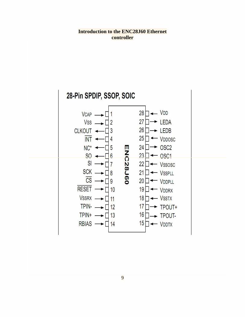
Introduction to the ENC28J60 Ethernet controller
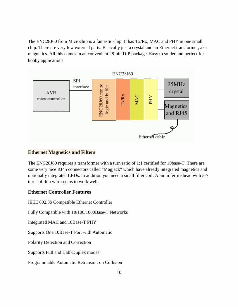
The ENC28J60 from Microchip is a fantastic chip. It has Tx/Rx, MAC and PHY in one smallchip. There are very few external parts. Basically just a crystal and an Ethernet transformer, akamagnetics. All this comes in an convenient 28-pin DIP package. Easy to solder and perfect for
hobby applications.
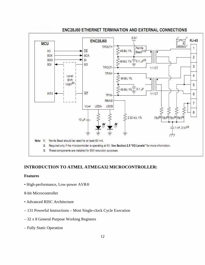
Ethernet Magnetics and Filters
The ENC28J60 requires a transformer with a turn ratio of 1:1 certified for 10base-T. There aresome very nice RJ45 connectors called "Magjack" which have already integrated magnetics andoptionally integrated LEDs. In addition you need a small filter coil. A 5mm ferrite bead with 5-7turns of thin wire seems to work well.
The use of microcontroller
Here I have used the ATMEL’s atmega32 which is the brain of this whole server system.(seeFurther details in circuit section)
The tcp/ip and http protocol implementation
Here for the starting of the webpage & server we have to implement the tcp/ip protocol suit andhttp protocols . for that here the tcp/ip stack is used with Ethernet controller IC.
6
Definition of Problem :
An embedded HTTP server is a component of a software system that implements
the http protocol. Examples of usage within an application might be:
To provide a thin-client interface for a traditional application..
To provide indexing reporting, and debugging tools during the development stage.
To implement a protocol for the distribution and acquisition of information to be
displayed in the regular interface — possibly a web service and possibly using xml as the
data format.
To develop a web application.
Design vis-à-vis User Requirements:
To operate this server we need just a computer with web browser .
Systems Planning :
Step1: choosing Ethernet controller IC
Step2: choose microcontroller
Step3: choose magjack with inbuilt Ethernet transformer
Step4: interface Ethernet controller with microcontroller through SPI
Step5: connect the circuit and solder it .
Step6: load the program on microcontroller
Step7: set ip address by connecting board with pc rs232 port
Step8: connect board through Ethernet jack with pc & check it on web browser
Methodology adopted, system implementation & details of hardware and software:
Methodology :
Step1:
7
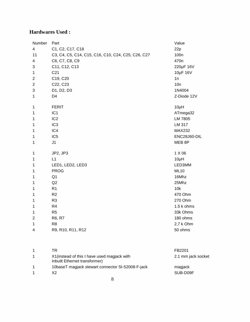
Hardwares Used :
Number Part Value4 C1, C2, C17, C18 22p11 C3, C4, C5, C14, C15, C16, C10, C24, C25, C26, C27 100n4 C6, C7, C8, C9 470n3 C11, C12, C13 220μF 16V1 C21 10μF 16V2 C19, C20 1n2 C22, C23 10n3 D1, D2, D3 1N40041 D4 Z-Diode 12V
1 FERIT 10μH1 IC1 ATmega321 IC2 LM 78051 IC3 LM 3171 IC4 MAX2321 IC5 ENC28J60-DIL1 J1 MEB 8P
1 JP2, JP3 1 X 061 L1 10μH1 LED1, LED2, LED3 LED3MM1 PROG ML101 Q1 16Mhz1 Q2 25Mhz1 R1 10k1 R2 470 Ohm1 R3 270 Ohm1 R4 1.5 k ohms1 R5 33k Ohms2 R6, R7 180 ohms1 R8 2,7 k Ohm4 R9, R10, R11, R12 50 ohms
1 TR FB22011 X1(instead of this I have used magjack with
Inbuilt Ethernet transformer)2.1 mm jack socket
1 10baseT magjack stewart connector SI-52008-F-jack magjack1 X2 SUB-D09F
8

Introduction to the ENC28J60 Ethernetcontroller
9
The ENC28J60 from Microchip is a fantastic chip. It has Tx/Rx, MAC and PHY in one smallchip. There are very few external parts. Basically just a crystal and an Ethernet transformer, akamagnetics. All this comes in an convenient 28-pin DIP package. Easy to solder and perfect for
hobby applications.
Ethernet Magnetics and Filters
The ENC28J60 requires a transformer with a turn ratio of 1:1 certified for 10base-T. There aresome very nice RJ45 connectors called "Magjack" which have already integrated magnetics andoptionally integrated LEDs. In addition you need a small filter coil. A 5mm ferrite bead with 5-7turns of thin wire seems to work well.
Ethernet Controller Features
IEEE 802.3ô Compatible Ethernet Controller
Fully Compatible with 10/100/1000Base-T Networks
Integrated MAC and 10Base-T PHY
Supports One 10Base-T Port with Automatic
Polarity Detection and Correction
Supports Full and Half-Duplex modes
Programmable Automatic Retransmit on Collision
10

SPI Interface with Clock Speeds Up to 20 MHz
Buffer
8-Kbyte Transmit/Receive Packet Dual Port SRAM
Configurable Transmit/Receive Buffer Size
Hardware Managed Circular Receive FIFO
Byte-Wide Random and Sequential Access with
Auto-Increment
Internal DMA for Fast Data Movement
Hardware Assisted Checksum Calculation for
Various Network Protocols
Medium Access Controller (MAC)
Features
Supports Unicast, Multicast and Broadcast
Packets
Programmable Receive Packet Filtering and Wake-up
Host on Logical AND or OR of the Following:
- Unicast destination address
- Multicast address
- Broadcast address
- Magic Packetô
- Group destination addresses as defined by
64-bit Hash Table
- Programmable Pattern Matching of up to
11
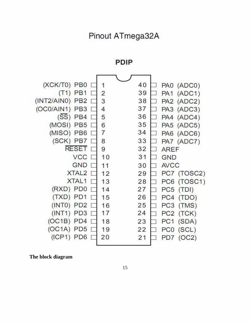
INTRODUCTION TO ATMEL ATMEGA32 MICROCONTROLLER:
Features
• High-performance, Low-power AVR®
8-bit Microcontroller
• Advanced RISC Architecture
– 131 Powerful Instructions – Most Single-clock Cycle Execution
– 32 x 8 General Purpose Working Registers
– Fully Static Operation
12

– On-chip 2-cycle Multiplier
• High Endurance Non-volatile Memory segments
– 32K Bytes of In-System Self-programmable Flash program memory
– 1024 Bytes EEPROM
– 2K Byte Internal SRAM
– Write/Erase Cycles: 10,000 Flash/100,000 EEPROM
– Data retention: 20 years at 85°C/100 years at 25°C(1)
– Optional Boot Code Section with Independent Lock Bits
• In-System Programming by On-chip Boot Program
• True Read-While-Write Operation
– Programming Lock for Software Security
• JTAG (IEEE std. 1149.1 Compliant) Interface
– Boundary-scan Capabilities According to the JTAG Standard
– Extensive On-chip Debug Support
– Programming of Flash, EEPROM, Fuses, and Lock Bits through the JTAG Interfa
• Peripheral Features
– Two 8-bit Timer/Counters with Separate Prescalers and Compare Modes
– One 16-bit Timer/Counter with Separate Prescaler, Compare Mode, and Capture
Mode
– Real Time Counter with Separate Oscillator
–Four PWM Channels
– 8-channel, 10-bit ADC
• 8 Single-ended Channels
• 7 Differential Channels in TQFP Package Only
13
• 2 Differential Channels with Programmable Gain at 1x, 10x, or 200x
– Byte-oriented Two-wire Serial Interface
– Programmable Serial USART
– Master/Slave SPI Serial Interface
– Programmable Watchdog Timer with Separate On-chip Oscillator
– On-chip Analog Comparator
• Special Microcontroller Features
– Power-on Reset and Programmable Brown-out Detection
– Internal Calibrated RC Oscillator
– External and Internal Interrupt Sources
– Six Sleep Modes: Idle, ADC Noise Reduction, Power-save, Power-down, Stan
and Extended Standby
• I/O and Packages
– 32 Programmable I/O Lines
– 40-pin PDIP, 44-lead TQFP, and 44-pad QFN/MLF
• Operating Voltages
– 2.7 - 5.5V for ATmega32A
• Speed Grades
– 0 - 16 MHz for ATmega32A
• Power Consumption at 1 MHz, 3V, 25°C for ATmega32A
– Active: 0.6 mA
– Idle Mode: 0.2 mA
– Power-down Mode: < 1 µA
14
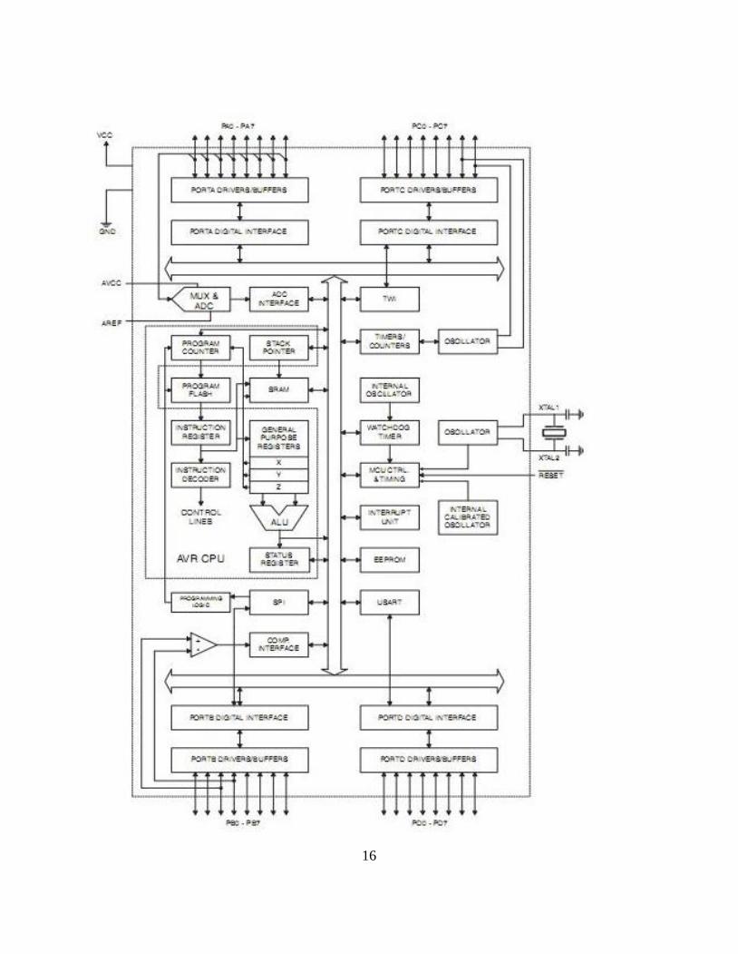
The block diagram
15
16
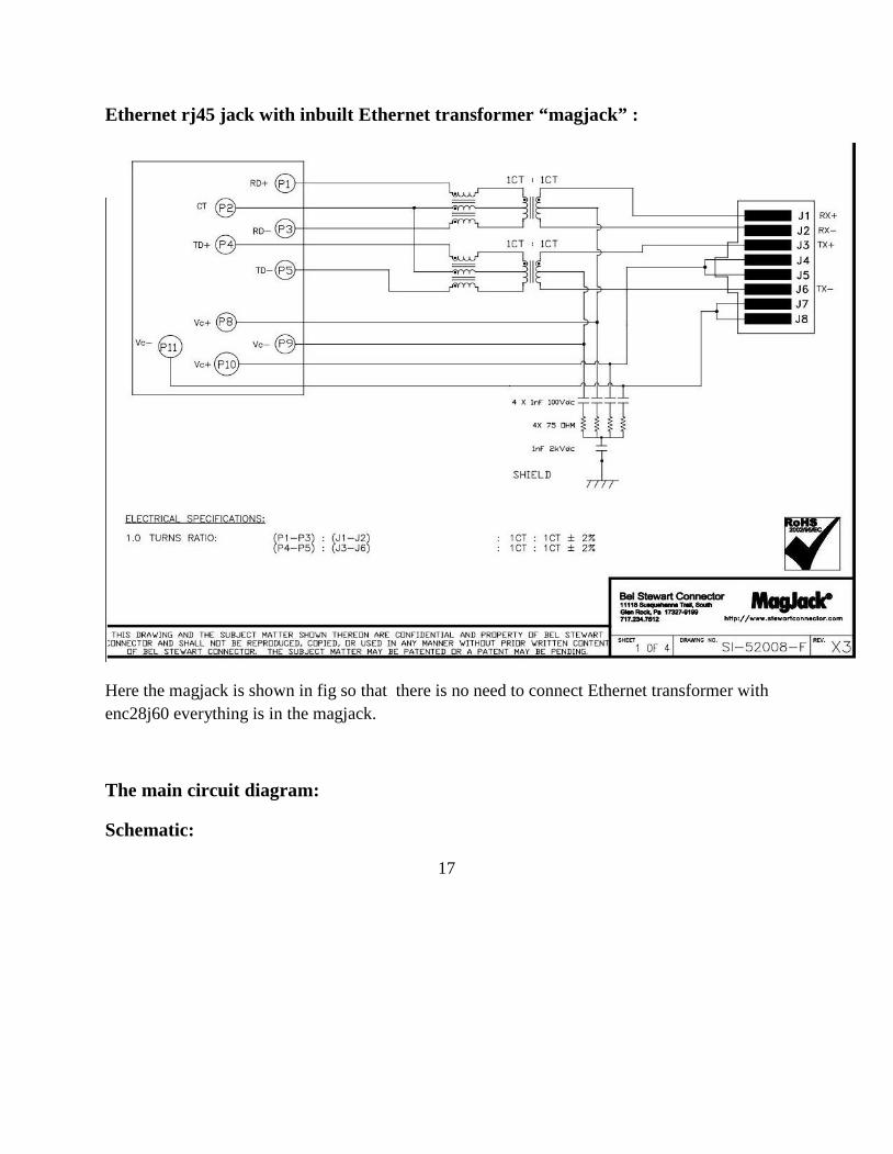
Ethernet rj45 jack with inbuilt Ethernet transformer “magjack” :
Here the magjack is shown in fig so that there is no need to connect Ethernet transformer withenc28j60 everything is in the magjack.
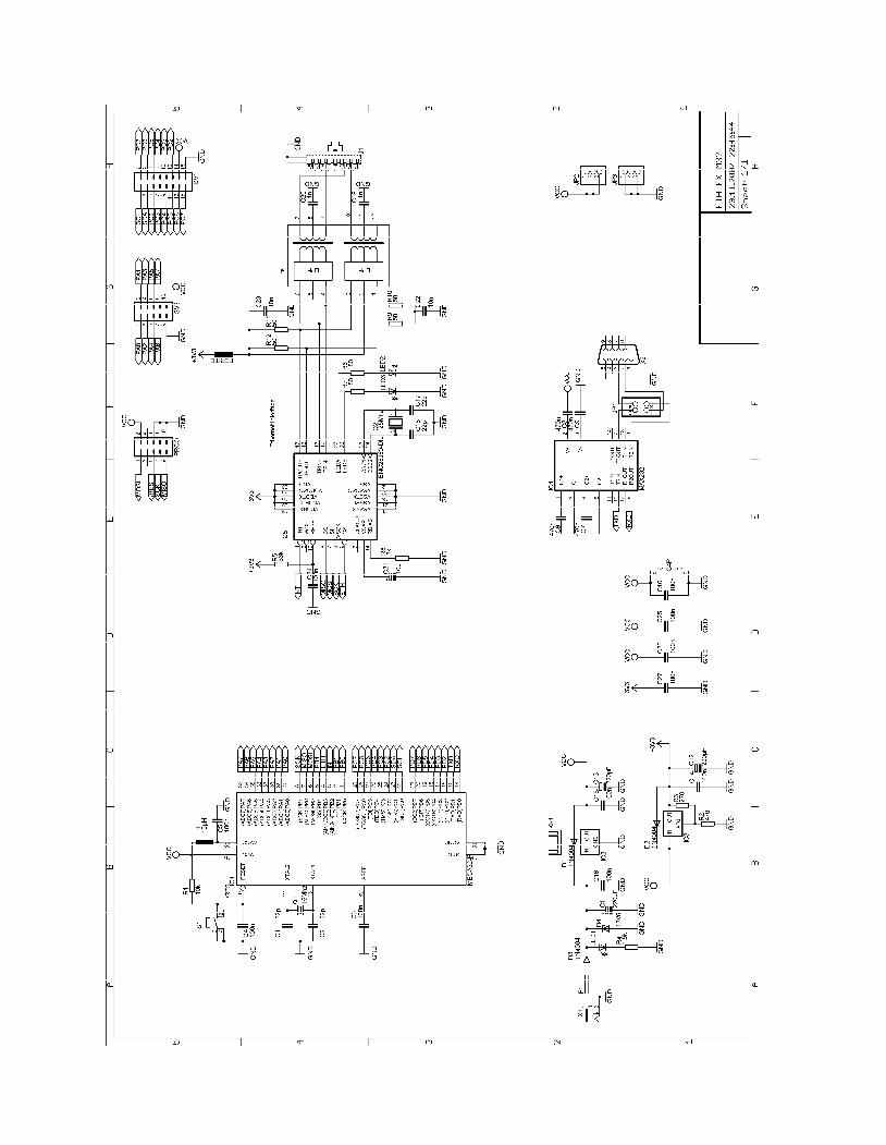
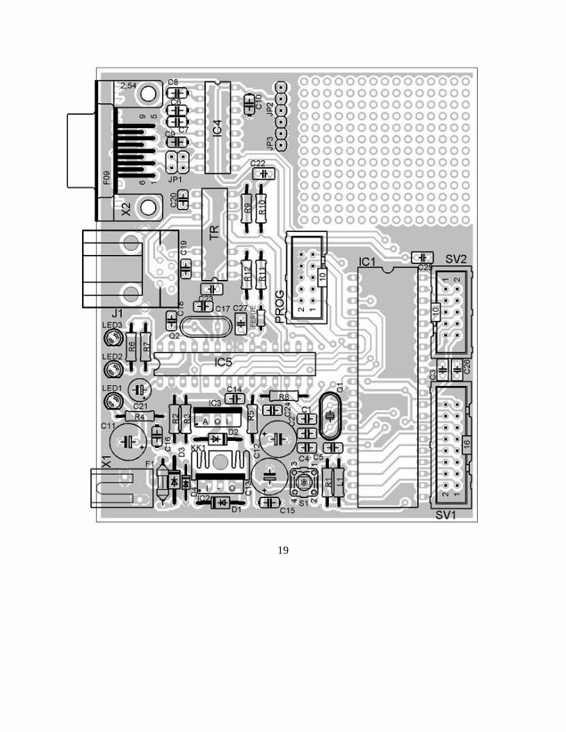
The main circuit diagram:
Schematic:
17
19
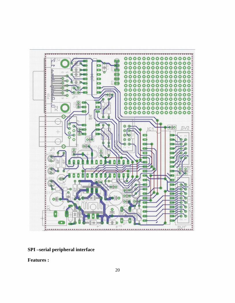
SPI –serial peripheral interface
Features :
20
• Full-duplex, Three-wire Synchronous Data Transfer
• Master or Slave Operation
• LSB First or MSB First Data Transfer
• Seven Programmable Bit Rates
• End of Transmission Interrupt Flag
• Write Collision Flag Protection
• Wake-up from Idle Mode
• Double Speed (CK/2) Master SPI Mode
The Serial Peripheral Interface (SPI) allows high-speed synchronous data transfer between the
ATmega32A and peripheral devices or between several AVR devices.
21
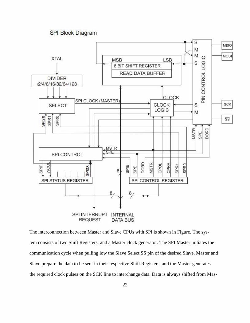
The interconnection between Master and Slave CPUs with SPI is shown in Figure. The sys-
tem consists of two Shift Registers, and a Master clock generator. The SPI Master initiates the
communication cycle when pulling low the Slave Select SS pin of the desired Slave. Master and
Slave prepare the data to be sent in their respective Shift Registers, and the Master generates
the required clock pulses on the SCK line to interchange data. Data is always shifted from Mas-
22

ter to Slave on the Master Out – Slave In, MOSI, line, and from Slave to Master on the Master In
– Slave Out, MISO, line. After each data packet, the Master will synchronize the Slave bypulling
high the Slave Select, SS, line.
When configured as a Master, the SPI interface has no automatic control of the SS line. This
must be handled by user software before communication can start. When this is done, writing a
byte to the SPI Data Register starts the SPI clock generator, and the hardware shifts the eight
bits into the Slave. After shifting one byte, the SPI clock generator stops, setting the end of
Transmission Flag (SPIF). If the SPI Interrupt Enable bit (SPIE) in the SPCR Register is set, an
interrupt is requested. The Master may continue to shift the next byte by writing it into SPDR, or
signal the end of packet by pulling high the Slave Select, SS line. The last incoming byte will be
kept in the Buffer Register for later use.
When configured as a Slave, the SPI interface will remain sleeping with MISO tri-stated as long
as the SS pin is driven high. In this state, software may update the contents of the SPI Data
Register, SPDR, but the data will not be shifted out by incoming clock pulses on the SCK pin
until the SS pin is driven low. As one byte has been completely shifted, the end of Transmission
Flag, SPIF is set. If the SPI Interrupt Enable bit, SPIE, in the SPCR Register is set, an interrupt
is requested. The Slave may continue to place new data to be sent into SPDR before reading
the incoming data. The last incoming byte will be kept in the Buffer Register for later use.
23
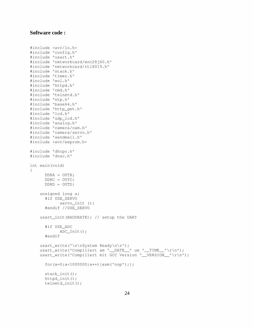
Software code :
#include <avr/io.h>#include "config.h"#include "usart.h"#include "networkcard/enc28j60.h"#include "networkcard/rtl8019.h"#include "stack.h"#include "timer.h"#include "wol.h"#include "httpd.h"#include "cmd.h"#include "telnetd.h"#include "ntp.h"#include "base64.h"#include "http_get.h"#include "lcd.h"#include "udp_lcd.h"#include "analog.h"#include "camera/cam.h"#include "camera/servo.h"#include "sendmail.h"#include <avr/eeprom.h>
#include "dhcpc.h"#include "dnsc.h"
int main(void){
DDRA = OUTA;DDRC = OUTC;DDRD = OUTD;
unsigned long a;#if USE_SERVO
servo_init ();#endif //USE_SERVO
usart_init(BAUDRATE); // setup the UART
#if USE_ADCADC_Init();
#endif
usart_write("\n\rSystem Ready\n\r");usart_write("Compiliert am "__DATE__" um "__TIME__"\r\n");usart_write("Compiliert mit GCC Version "__VERSION__"\r\n");
for(a=0;a<1000000;a++){asm("nop");};
stack_init();httpd_init();telnetd_init();
24
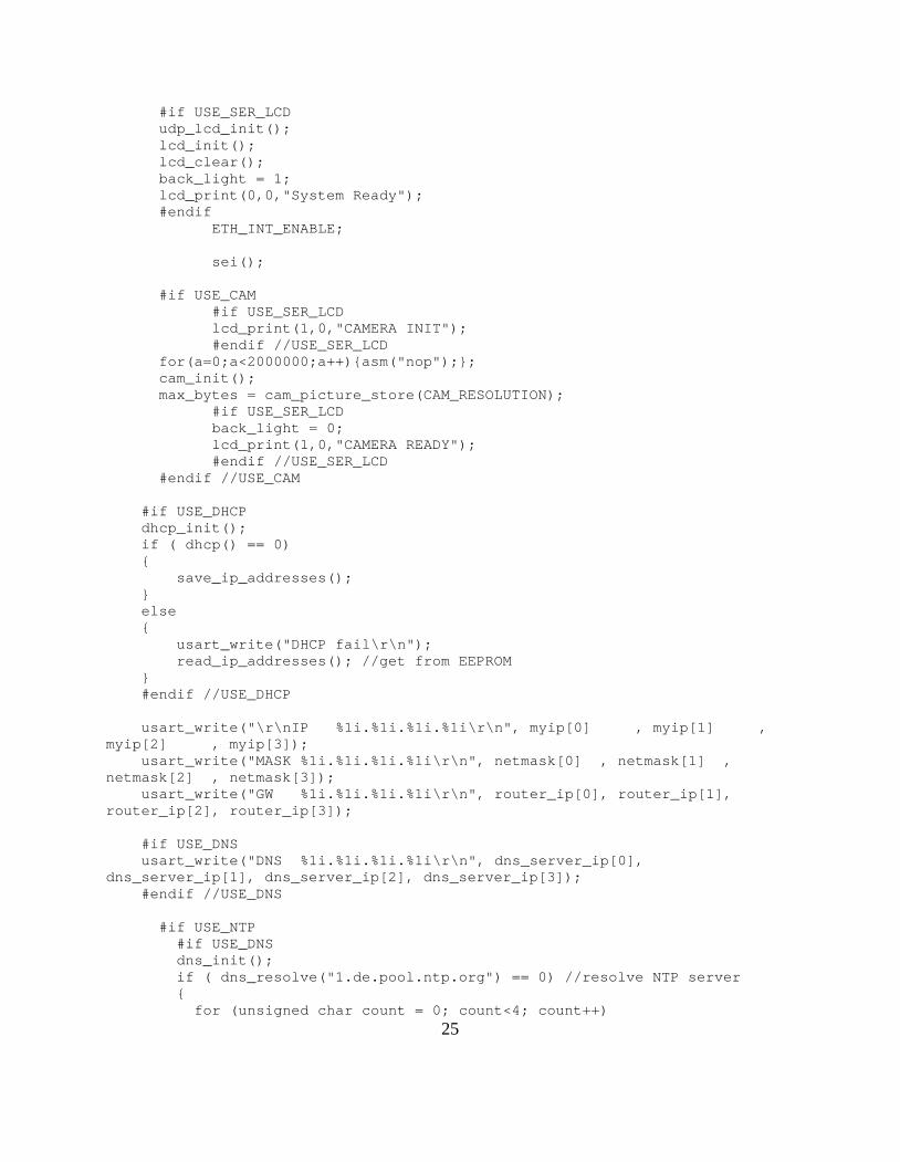
#if USE_SER_LCDudp_lcd_init();lcd_init();lcd_clear();back_light = 1;lcd_print(0,0,"System Ready");#endif
ETH_INT_ENABLE;
sei();
#if USE_CAM#if USE_SER_LCDlcd_print(1,0,"CAMERA INIT");#endif //USE_SER_LCD
for(a=0;a<2000000;a++){asm("nop");};cam_init();max_bytes = cam_picture_store(CAM_RESOLUTION);
#if USE_SER_LCDback_light = 0;lcd_print(1,0,"CAMERA READY");#endif //USE_SER_LCD
#endif //USE_CAM
#if USE_DHCPdhcp_init();if ( dhcp() == 0){
save_ip_addresses();}else{
usart_write("DHCP fail\r\n");read_ip_addresses(); //get from EEPROM
}#endif //USE_DHCP
usart_write("\r\nIP %1i.%1i.%1i.%1i\r\n", myip[0] , myip[1] ,myip[2] , myip[3]);
usart_write("MASK %1i.%1i.%1i.%1i\r\n", netmask[0] , netmask[1] ,netmask[2] , netmask[3]);
usart_write("GW %1i.%1i.%1i.%1i\r\n", router_ip[0], router_ip[1],router_ip[2], router_ip[3]);
#if USE_DNSusart_write("DNS %1i.%1i.%1i.%1i\r\n", dns_server_ip[0],
dns_server_ip[1], dns_server_ip[2], dns_server_ip[3]);#endif //USE_DNS
#if USE_NTP#if USE_DNSdns_init();if ( dns_resolve("1.de.pool.ntp.org") == 0) //resolve NTP server{
for (unsigned char count = 0; count<4; count++)
25
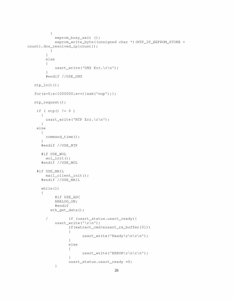
{eeprom_busy_wait ();eeprom_write_byte((unsigned char *)(NTP_IP_EEPROM_STORE +
count),dns_resolved_ip[count]);}
}else{
usart_write("DNS Err.\r\n");}#endif //USE_DNS
ntp_init();
for(a=0;a<1000000;a++){asm("nop");};
ntp_request();
if ( ntp() != 0 ){
usart_write("NTP Err.\r\n");}
else{
command_time();}#endif //USE_NTP
#if USE_WOLwol_init();
#endif //USE_WOL
#if USE_MAILmail_client_init();
#endif //USE_MAIL
while(1){
#if USE_ADCANALOG_ON;#endif
eth_get_data();
/ if (usart_status.usart_ready){usart_write("\r\n");
if(extract_cmd(&usart_rx_buffer[0])){
usart_write("Ready\r\n\r\n");}else{
usart_write("ERROR\r\n\r\n");}usart_status.usart_ready =0;
}26
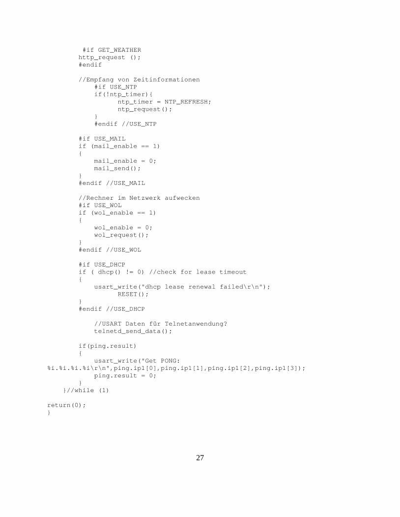
#if GET_WEATHERhttp_request ();#endif
//Empfang von Zeitinformationen#if USE_NTPif(!ntp_timer){
ntp_timer = NTP_REFRESH;ntp_request();
}#endif //USE_NTP
#if USE_MAILif (mail_enable == 1){
mail_enable = 0;mail_send();
}#endif //USE_MAIL
//Rechner im Netzwerk aufwecken#if USE_WOLif (wol_enable == 1){
wol_enable = 0;wol_request();
}#endif //USE_WOL
#if USE_DHCPif ( dhcp() != 0) //check for lease timeout{
usart_write("dhcp lease renewal failed\r\n");RESET();
}#endif //USE_DHCP
//USART Daten für Telnetanwendung?telnetd_send_data();
if(ping.result){
usart_write("Get PONG:%i.%i.%i.%i\r\n",ping.ip1[0],ping.ip1[1],ping.ip1[2],ping.ip1[3]);
ping.result = 0;}
}//while (1)
return(0);}
27
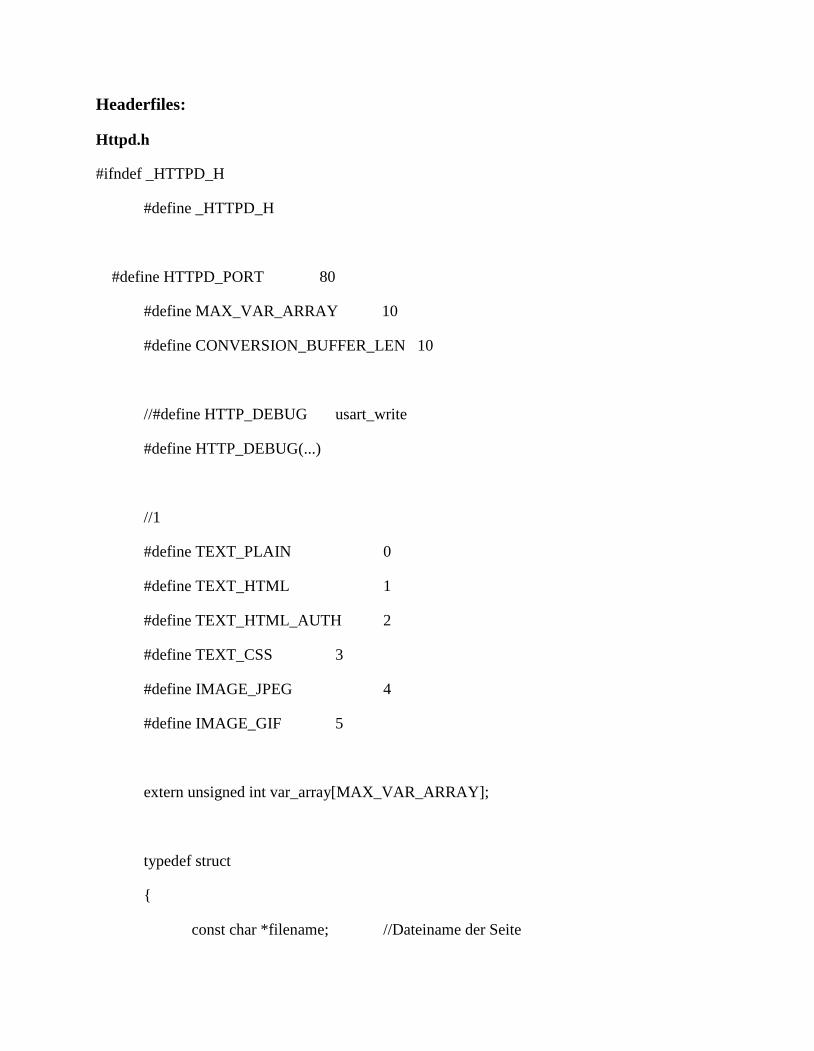
Headerfiles:
Httpd.h
#ifndef _HTTPD_H
#define _HTTPD_H
#define HTTPD_PORT 80
#define MAX_VAR_ARRAY 10
#define CONVERSION_BUFFER_LEN 10
//#define HTTP_DEBUG usart_write
#define HTTP_DEBUG(...)
//1
#define TEXT_PLAIN 0
#define TEXT_HTML 1
#define TEXT_HTML_AUTH 2
#define TEXT_CSS 3
#define IMAGE_JPEG 4
#define IMAGE_GIF 5
extern unsigned int var_array[MAX_VAR_ARRAY];
typedef struct
{
const char *filename; //Dateiname der Seite
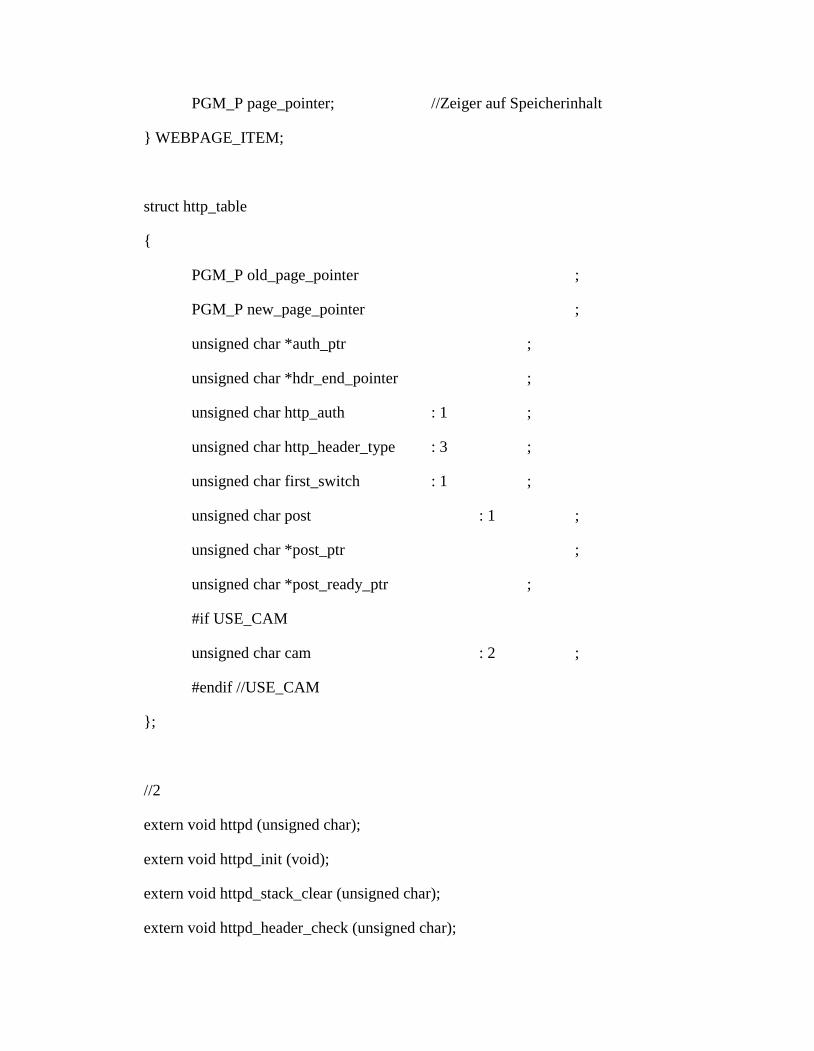
PGM_P page_pointer; //Zeiger auf Speicherinhalt
} WEBPAGE_ITEM;
struct http_table
{
PGM_P old_page_pointer ;
PGM_P new_page_pointer ;
unsigned char *auth_ptr ;
unsigned char *hdr_end_pointer ;
unsigned char http_auth : 1 ;
unsigned char http_header_type : 3 ;
unsigned char first_switch : 1 ;
unsigned char post : 1 ;
unsigned char *post_ptr ;
unsigned char *post_ready_ptr ;
#if USE_CAM
unsigned char cam : 2 ;
#endif //USE_CAM
};
//2
extern void httpd (unsigned char);
extern void httpd_init (void);
extern void httpd_stack_clear (unsigned char);
extern void httpd_header_check (unsigned char);
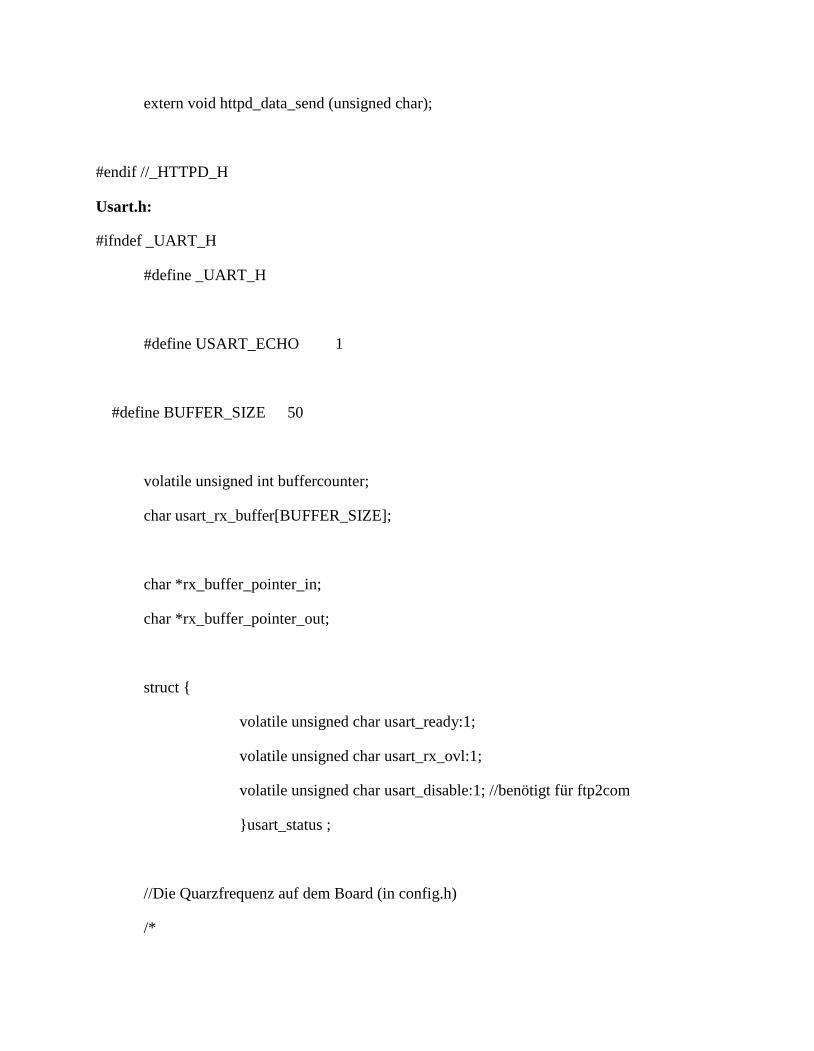
extern void httpd_data_send (unsigned char);
#endif //_HTTPD_H
Usart.h:
#ifndef _UART_H
#define _UART_H
#define USART_ECHO 1
#define BUFFER_SIZE 50
volatile unsigned int buffercounter;
char usart_rx_buffer[BUFFER_SIZE];
char *rx_buffer_pointer_in;
char *rx_buffer_pointer_out;
struct {
volatile unsigned char usart_ready:1;
volatile unsigned char usart_rx_ovl:1;
volatile unsigned char usart_disable:1; //benötigt für ftp2com
}usart_status ;
//Die Quarzfrequenz auf dem Board (in config.h)
/*
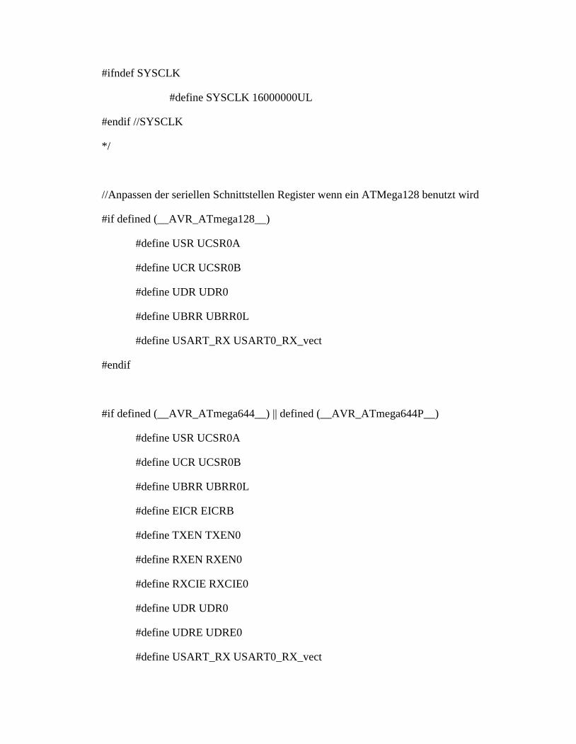
#ifndef SYSCLK
#define SYSCLK 16000000UL
#endif //SYSCLK
*/
//Anpassen der seriellen Schnittstellen Register wenn ein ATMega128 benutzt wird
#if defined (__AVR_ATmega128__)
#define USR UCSR0A
#define UCR UCSR0B
#define UDR UDR0
#define UBRR UBRR0L
#define USART_RX USART0_RX_vect
#endif
#if defined (__AVR_ATmega644__) || defined (__AVR_ATmega644P__)
#define USR UCSR0A
#define UCR UCSR0B
#define UBRR UBRR0L
#define EICR EICRB
#define TXEN TXEN0
#define RXEN RXEN0
#define RXCIE RXCIE0
#define UDR UDR0
#define UDRE UDRE0
#define USART_RX USART0_RX_vect
#endif
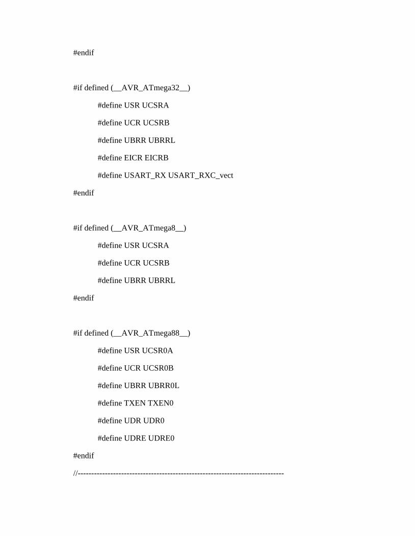
#if defined (__AVR_ATmega32__)
#define USR UCSRA
#define UCR UCSRB
#define UBRR UBRRL
#define EICR EICRB
#define USART_RX USART_RXC_vect
#endif
#if defined (__AVR_ATmega8__)
#define USR UCSRA
#define UCR UCSRB
#define UBRR UBRRL
#endif
#if defined (__AVR_ATmega88__)
#define USR UCSR0A
#define UCR UCSR0B
#define UBRR UBRR0L
#define TXEN TXEN0
#define UDR UDR0
#define UDRE UDRE0
#endif
//----------------------------------------------------------------------------
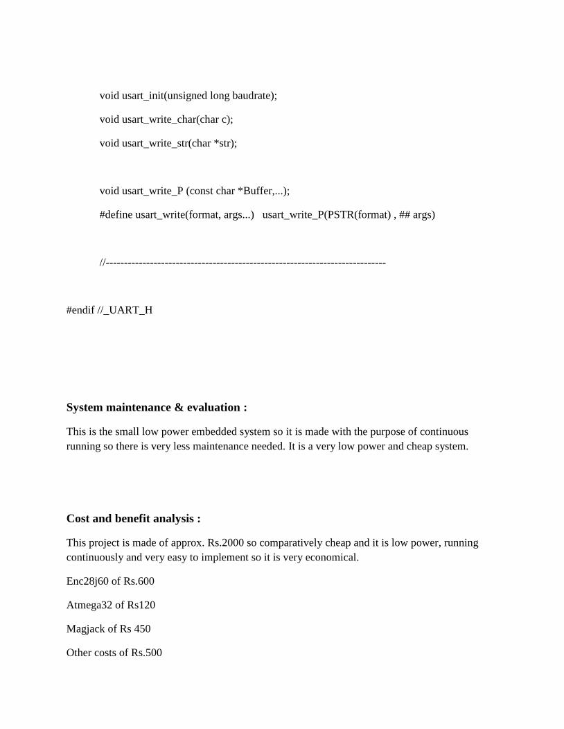
void usart_init(unsigned long baudrate);
void usart_write_char(char c);
void usart_write_str(char *str);
void usart_write_P (const char *Buffer,...);
#define usart_write(format, args...) usart_write_P(PSTR(format) , ## args)
//----------------------------------------------------------------------------
#endif //_UART_H
System maintenance & evaluation :
This is the small low power embedded system so it is made with the purpose of continuousrunning so there is very less maintenance needed. It is a very low power and cheap system.
Cost and benefit analysis :
This project is made of approx. Rs.2000 so comparatively cheap and it is low power, runningcontinuously and very easy to implement so it is very economical.
Enc28j60 of Rs.600
Atmega32 of Rs120
Magjack of Rs 450
Other costs of Rs.500

Pcb of Rs. 100
Detailed life cycle of the project :
Step1: make schematic and layout using eagle cad software and get pcb
Step2: buy components
Step3: solder them & make board
Step4: make program with using winavr-avrgcc, avrstudio IDE
Step5: lord program on atmega32 microcontroller
Step6: get ip with using rs232
Step7: connect board with pc Ethernet and run the system
Methodology used for testing :
I have used stk500 programmer and avr studio 4 with winavr for programming and development.
Annexure :
Brief background of the organization where the student has developed the project:
Organization name: Ahmedabad Institute Of Technology(AIT)
Ahmedabad Institute Of Technology(AIT) is affiliated with Gujarat University .
29
DATASHEETS…………………..atmega32,enc28j60, magjack ,max232,LM7805,LM317,
30
References :
--Bibliography
TCP/IP Lean: Web Servers for Embedded SystemsBy: Jeremy Bentham
Networking and Internetworking with MicrocontrollersBy: Fred Eady
--websites
http://www.tuxgraphics.org/
http://www.electronicfr.com/
http://ulrichradig.de/
this is the last page